EP3163693A1 - Spark plug - Google Patents
Spark plug Download PDFInfo
- Publication number
- EP3163693A1 EP3163693A1 EP15814683.7A EP15814683A EP3163693A1 EP 3163693 A1 EP3163693 A1 EP 3163693A1 EP 15814683 A EP15814683 A EP 15814683A EP 3163693 A1 EP3163693 A1 EP 3163693A1
- Authority
- EP
- European Patent Office
- Prior art keywords
- precious metal
- metal tip
- melt
- virtual straight
- straight line
- Prior art date
- Legal status (The legal status is an assumption and is not a legal conclusion. Google has not performed a legal analysis and makes no representation as to the accuracy of the status listed.)
- Granted
Links
Images


Classifications
-
- H—ELECTRICITY
- H01—ELECTRIC ELEMENTS
- H01T—SPARK GAPS; OVERVOLTAGE ARRESTERS USING SPARK GAPS; SPARKING PLUGS; CORONA DEVICES; GENERATING IONS TO BE INTRODUCED INTO NON-ENCLOSED GASES
- H01T13/00—Sparking plugs
- H01T13/20—Sparking plugs characterised by features of the electrodes or insulation
- H01T13/39—Selection of materials for electrodes
-
- H—ELECTRICITY
- H01—ELECTRIC ELEMENTS
- H01T—SPARK GAPS; OVERVOLTAGE ARRESTERS USING SPARK GAPS; SPARKING PLUGS; CORONA DEVICES; GENERATING IONS TO BE INTRODUCED INTO NON-ENCLOSED GASES
- H01T13/00—Sparking plugs
- H01T13/20—Sparking plugs characterised by features of the electrodes or insulation
-
- H—ELECTRICITY
- H01—ELECTRIC ELEMENTS
- H01T—SPARK GAPS; OVERVOLTAGE ARRESTERS USING SPARK GAPS; SPARKING PLUGS; CORONA DEVICES; GENERATING IONS TO BE INTRODUCED INTO NON-ENCLOSED GASES
- H01T13/00—Sparking plugs
- H01T13/20—Sparking plugs characterised by features of the electrodes or insulation
- H01T13/32—Sparking plugs characterised by features of the electrodes or insulation characterised by features of the earthed electrode
Definitions
- the present invention relates to spark plugs.
- a spark plug As a conventional spark plug, a spark plug has been known which includes an electrode (a center electrode or a ground electrode) to which an electrode tip (hereinafter referred to as "precious metal tip") formed of a precious metal or an alloy containing a precious metal as a main component is joined (refer to Patent Document 1, for example).
- a precious metal tip is joined to an electrode base material by laser welding. Specifically, the precious metal tip is irradiated with a laser beam along its outer periphery, whereby the precious metal tip is joined to the electrode base material.
- a melt portion in which the material of the precious metal tip and the material of the electrode base material are melted is formed between the precious metal tip and the electrode base material.
- an oxide film (hereinafter also referred to as an oxide scale) may be formed on the surface of the melt portion.
- the oxide scale is formed, at the melt portion interface, so as to gradually grow from an outer peripheral portion near the outside air toward the inside of the melt portion interface.
- Patent Document 1 Japanese Patent Application Laid-Open ( kokai ) No. 2013-178912
- the present invention is made to solve, at least partially, the above problem, and can be embodied in the following modes.
- the present invention can be embodied in various forms other than the spark plug.
- the present invention can be embodied in forms of an internal combustion engine on which the spark plug is mounted, a vehicle including the internal combustion engine, and the like.
- the present invention can be embodied in the form of a method for manufacturing the spark plug.
- FIG. 1 is a partially cross-sectional view of a spark plug 100 as an embodiment of the present invention.
- the spark plug 100 has an elongated shape extending along an axis Ax (a center axis of the spark plug 100).
- the right side of the axis Ax indicated by a dot-dash line shows an exterior front view
- the left side of the axis Ax shows a sectional view where the spark plug 100 is sectioned by a plane that passes the axis Ax.
- the lower side in FIG. 1 (indicated by an arrow X in FIG. 1 ) is referred to as the front side
- the upper side in FIG. 1 is referred to as the rear side.
- the spark plug 100 includes a ceramic insulator 10, a center electrode 20, a ground electrode 30, a metal terminal 40, and a metallic shell 50.
- the rod-shaped center electrode 20 projecting from a front end of the ceramic insulator 10 extends through the interior of the ceramic insulator 10 and is electrically connected to the metal terminal 40 provided at a rear end of the ceramic insulator 10.
- the outer periphery of the center electrode 20 is held by the ceramic insulator 10, and the outer periphery of the ceramic insulator 10 is held by the metallic shell 50 at a position apart from the metal terminal 40.
- the ground electrode 30 electrically connected to the metallic shell 50 forms a spark gap which is a gap for generating a spark, between the ground electrode 30 and the front end of the center electrode 20.
- the spark plug 100 is attached, through the metallic shell 50, to a threaded attachment hole 201 provided in an engine head 200 of an internal combustion engine.
- a high voltage of 20,000 to 30,000 V is applied to the metal terminal 40, a spark is generated at the spark gap formed between the center electrode 20 and the ground electrode 30.
- the ceramic insulator 10 is an insulator formed through firing of a ceramic material such as alumina.
- the ceramic insulator 10 is a cylindrical member having, in the center thereof, an axial hole 12 in which the center electrode 20 and the metal terminal 40 are accommodated.
- the ceramic insulator 10 has a central trunk portion 19 formed at the center thereof in the axial direction and having an increased outer diameter.
- a rear trunk portion 18 for insulation between the metal terminal 40 and the metallic shell 50 is formed on the metal terminal 40 side relative to the central trunk portion 19.
- a front trunk portion 17 having an outer diameter smaller than that of the rear trunk portion 18 is formed on the center electrode 20 side relative to the central trunk portion 19.
- a leg portion 13 having an outer diameter which is smaller than that of the front trunk portion 17 and decreases toward the front side is formed frontward of the front trunk portion 17.
- the metallic shell 50 is a cylindrical metallic member that surrounds a portion of the ceramic insulator 10 extending from a part of the rear trunk portion 18 to the leg portion 13 to hold the ceramic insulator 10.
- the metallic shell 50 is formed of low carbon steel, and the entirety of the metallic shell 50 is subjected to plating such as nickel plating or zinc plating.
- the metallic shell 50 has a tool engagement portion 51, a threaded attachment portion 52, and a gasket receiving portion 54.
- a tool (not shown) used for fixing the spark plug 100 to an engine head 200 is engaged with the tool engagement portion 51 of the metallic shell 50.
- the threaded attachment portion 52 of the metallic shell 50 has a screw thread to be screwed into the threaded attachment hole 201 of the engine head 200.
- the gasket receiving portion 54 of the metallic shell 50 projects radially outward relative to the threaded attachment portion 52 and is formed in a flange shape, on the rear side of the threaded attachment portion 52.
- a gasket 5 which is a substantially annular-shaped solid member is fitted to the metallic shell 50 so as to be in contact with a front-side end portion of the gasket receiving portion 54.
- the gasket 5 secures sufficient seal between the gasket receiving portion 54 of the spark plug 100 and the engine head 200.
- a front end surface 57 of the metallic shell 50 is formed in a circular shape having an opening in a center portion thereof. At the center portion, the center electrode 20 projects from the leg portion 13 of the ceramic insulator 10.
- a thin crimp portion 53 is provided on the rear side of the metallic shell 50 with respect to the tool engagement portion 51.
- a compressive deformation portion 58 is provided between the gasket receiving portion 54 and the tool engagement portion 51.
- Annular ring members 6 and 7 are interposed between an inner peripheral surface of the metallic shell 50 from the tool engagement portion 51 to the crimp portion 53, and an outer peripheral surface of the rear trunk portion 18 of the ceramic insulator 10. Further, powder of talc 9 is charged between the ring members 6 and 7.
- the spark plug 100 When the spark plug 100 is manufactured, crimping is performed in which the crimp portion 53 is bent inward and pressed frontward, whereby the compressive deformation portion 58 is compressed and deformed. As a result of the crimping, the ceramic insulator 10 is pressed frontward in the metallic shell 50 through the ring members 6 and 7 and the talc 9. As a result of this pressing, the talc 9 is compressed in the direction of the axis Ax, whereby the airtightness of the metallic shell 50 is improved.
- a ceramic step portion 15 located at a base end of the leg portion 13 of the ceramic insulator 10 is pressed, through a ring-shaped sheet packing 8, against a metal-shell internal step portion 56 formed at the position of the threaded attachment portion 52.
- the sheet packing 8 is a member for maintaining airtightness between the metallic shell 50 and the ceramic insulator 10, and prevents combustion gas from flowing out.
- the center electrode 20 includes an electrode base material 25 which is a rod-shaped member extending in the direction of the axis Ax.
- the electrode base material 25 is formed of a nickel alloy containing nickel as a main component.
- the electrode base material 25 has, therein, a core member formed of a material having higher thermal conductivity than the electrode base material 25, such as copper or an alloy containing copper as a main component.
- the center electrode 20 according to the present embodiment further includes, at a front end of the electrode base material 25, a precious metal tip for improving resistance to spark-induced erosion and resistance to oxidation-induced erosion. The structure of the front end portion of the center electrode 20 will be described later in detail.
- the center electrode 20 is inserted in the axial hole 12 of the ceramic insulator 10, with the front end of the electrode base material 25 projecting from the axial hole 12 of the ceramic insulator 10, and is electrically connected to the metal terminal 40 through a ceramic resistor 3 and a seal body 4.
- the ground electrode 30 is a rod-shaped member, and has a base end welded to the front end surface 57 of the metallic shell 50.
- the front side of the ground electrode 30 is bent in a direction intersecting the axis Ax, and the front end portion of the ground electrode 30 faces the front end surface of the center electrode 20 on the axis Ax.
- a precious metal tip similar to the center electrode 20 may be provided at a position opposed to the center electrode 20 at the front end portion of the ground electrode 30.
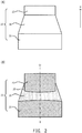
- FIG. 2 is an enlarged explanatory view showing the structure of the front end portion of the center electrode 20.
- FIG. 2(A) is a side view showing the appearance of the front end portion of the center electrode 20
- FIG. 2(B) is a cross-sectional view showing a cross section including a center axis O of a precious metal tip 27 included in the center electrode 20.
- FIG. 2(A) the above-described front side of the spark plug 100 is indicated by an arrow X.
- the center axis O of the precious metal tip 27 coincides with the axis Ax as the center axis of the spark plug 100.
- the precious metal tip 27 is a cylindrical member formed of a precious metal (e.g., platinum, iridium, ruthenium, rhodium, or the like) or an alloy containing not less than 50 wt% of a precious metal as a main component, and is joined to the front end surface of the electrode base material 25 by laser welding. Therefore, a melt portion 26 in which the electrode base material 25 and the precious metal tip 27 are melted is formed between the front end surface of the electrode base material 25 and the precious metal tip 27. In the present embodiment, the melt portion 26 is formed so as to cover the entire front end surface of the electrode base material 25.
- a precious metal e.g., platinum, iridium, ruthenium, rhodium, or the like
- the diameter of the cross section perpendicular to the center axis O (the diameter of the end surface on the front side) can be, for example, 0.3 mm or more, and preferably 0.4 mm or more.
- the diameter of the cross section of the precious metal tip 27 can be, for example, 1.5 mm or less, and preferably 1.2 mm or less.
- the front end surface to which the precious metal tip 27 is joined may have a size enough to be in contact with the entire rear end surface of the precious metal tip 27.
- the diameter of the front end surface of the electrode base material 25 may be about 0.2 to 0.4 mm larger than the diameter of the rear end surface of the precious metal tip 27, in terms of facilitating welding.
- a melt sag 28 is formed in the melt portion 26.
- the melt sag 28 is formed as a portion of a melt forming the melt portion 26. That is, the melt sag 28 is formed such that a portion of the melt extends frontward along the side surface of the precious metal tip 27, from near the interface between the electrode base material 25 and the precious metal tip 27, when the electrode base material 25 and the precious metal tip 27 are welded (refer to FIG. 2(B) ).
- the melt sag 28 is formed over the entire circumference on the side surface of the precious metal tip 27.
- Welding of the electrode base material 25 and the precious metal tip 27 may be performed by bringing the front end surface of the electrode base material 25 into contact with the rear end surface of the precious metal tip 27, and irradiating an area including the contact portions thereof, with a laser beam, from the outer peripheral side of the precious metal tip 27 toward the inside thereof.
- the irradiation with the laser beam is performed from the outer peripheral side of the precious metal tip 27 toward the center axis O of the precious metal tip 27. It is desirable that the irradiation with the laser beam is uniformly performed over the entire circumference of the precious metal tip 27.
- Welding of the electrode base material 25 and the precious metal tip 27 may employ various devices capable of emitting laser beams, such as a YAG laser, a carbon dioxide gas laser, a semiconductor laser, and a fiber laser.
- the employed laser may be a pulse wave (PW) oscillation laser or a continuous wave (CW) oscillation laser.
- PW pulse wave
- CW continuous wave
- a lens or an oscillator in the laser irradiation device may be optimized, and a condition selected from the laser output and the laser irradiation time may be adjusted.
- a fiber laser in terms of increasing the amount of energy per irradiation width.
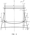
- FIG. 3 is a cross-sectional view for explaining a specific shape of the melt sag 28.
- FIG. 3 shows a cross section, including the center axis O, of the front end portion of the center electrode 20.
- a line corresponding to a front-side end surface of the precious metal tip 27 is indicated as a line S, and the line S has a length D.
- the melt sag 28 formed in the center electrode 20 according to the present embodiment has a shape as follows.
- end point P3 the end point positioned on the same side as the virtual straight line L1 with respect to the center axis O is referred to as an end point P3
- end point P4 the end point positioned on the same side as the virtual straight line L2 with respect to the center axis O is referred to as an end point P4.
- a straight line which passes the end point P3, P4 and is parallel to the center axis O is referred to as a virtual straight line L4, L5, respectively.
- end point P5 the end point on the virtual straight line L5 is referred to as an end point P6.
- intersection point P7, P8 An intersection point of the virtual straight line L4, L5 and the virtual straight line L3 is referred to as an intersection point P7, P8, respectively.
- a distance X1 between the intersection point P7 and the end point P5 and a distance X2 between the intersection point P8 and the end point P6 are each 0.092 mm or more.
- a rear end of a portion overlapping the virtual straight line L4 is referred to as a point P9
- a rear end of a portion overlapping the virtual straight line L5 is referred to as a point P10.
- an area between the points P5 and P9 and an area between the points P6 and P10 each are an area where the surface of the precious metal tip 27 is not substantially melted.
- an area between the points P9 and P10 is an area where the surface of the precious metal tip 27 is melted. Therefore, in the specification of the present application, in the area where the precious metal tip 27 and the melt portion 26 are in contact with each other, the area between the points P9 and P10 is also referred to as an "interface between the precious metal tip 27 and the melt portion 26".
- the interface indicated by P9-P10 where the surface of the precious metal tip 27 is melted is an area which significantly contributes to the joint strength between the precious metal tip 27 and the electrode base material 25.
- the shape of the melt sag 28 described with reference to FIG. 3 is obtained at any cross section, including the center axis O, of the front end portion of the center electrode 20.
- the melt sag 28, which is a part of the melt portion 26 extending frontward, is formed on the side surface of the precious metal tip 27 disposed at the front end portion of the center electrode 20. Therefore, entry of the air into the interface between the precious metal tip 27 and the melt portion 26 can be suppressed, thereby suppressing formation of the oxide scale that is lower in strength than the precious metal tip 27 and the melt portion 26, at the interface between the precious metal tip 27 and the melt portion 26. As a result, when the heating and cooling cycles are repeated in the spark plug 100, it is possible to suppress occurrence of crack due to a difference in thermal expansion coefficient between the precious metal tip 27 and the electrode base material 25 at the interface between the precious metal tip 27 and the melt portion 26.
- the melt sag 28 has a function as a seal portion which suppresses entry of the air into the interface between the precious metal tip 27 and the melt portion 26. Therefore, by forming the melt sag 28 to be long along the center axis O, the effect of suppressing growth of the oxide scale and extension of crack at the interface between the precious metal tip 27 and the melt portion 26 can be improved.
- the condition that the length (corresponding to the distance X1, X2 in FIG. 3 ) of the melt sag 28 from a predetermined reference position corresponding to the virtual straight line L3 shown in FIG. 3 along the direction of the center axis O is 0.092 mm or more, is satisfied over the entire circumference on the side surface of the precious metal tip 27. Therefore, growth of the oxide scale can be effectively suppressed over the entire interface between the precious metal tip 27 and the melt portion 26.
- the melt sag which has been considered to be undesirable in terms of appearance, is intentionally formed to a predetermined length or more, whereby reliability of the joint of the precious metal tip 27 is improved, resulting in increase in durability of the spark plug 100.
- the melt sag 28 is not present on the front-side end surface of the precious metal tip 27. The cause of this is to suppress the melt sag 28 from adversely affecting ignitability in the spark plug 100.
- the above-described length of the melt sag 28 is the length for securing the function thereof as the seal portion that suppresses entry of the air into the interface between the precious metal tip 27 and the melt portion 26. Therefore, the effect achieved by setting the length of the melt sag 28 in the direction of the center axis O to the above-described value is the effect achieved regardless of the size of the precious metal tip 27 and the material of the precious metal tip 27.
- the virtual straight line L3 is a position to be a reference for specifying the length, in the direction of the center axis O, of the melt sag 28 formed on the side surface of the precious metal tip 27.
- the virtual straight line L3 is specified as follows.
- the effect obtained by providing the melt sag 28 is achieved when the melt sag 28 covers the side surface of the precious metal tip 27 to suppress entry of the air into the interface between the precious metal tip 27 and the melt portion 26. Therefore, it is considered that the reference that defines the length of the melt sag 28 should be determined on the basis of the position of the interface between the precious metal tip 27 and the melt portion 26 at the rear-side end portion of the precious metal tip 27.
- the shape of the interface between the precious metal tip 27 and the melt portion 26 can vary depending on the welding condition.
- the melt sag 28 is provided on the side surface of the precious metal tip 27 as in the present embodiment, when the high-temperature melt formed of the precious metal tip 27 and the electrode base material 25 being melted extends frontward on the side surface of the precious metal tip 27, the side surface of the precious metal tip 27 is melted to some degree by being in contact with the melt.
- the degree of the melting of the side surface of the precious metal tip 27 is greater in the position closer to the rear side where the high-temperature melt is supplied.
- the distance of "9D/20" from the center axis O, which defines the virtual straight line L1, L2 used for obtaining the virtual straight line L3 in the present embodiment is a value experientially obtained by the inventors of the present application, as a position at which influence of the melting of the side surface of the precious metal tip 27 due to the high-temperature melt is sufficiently reduced.
- the virtual straight line L3 to be the reference is obtained by connecting the intersection points P1 and P2 which are the intersection points of the virtual straight lines L1 and L2 each apart from the center axis O by the distance of "9D/20" and the interface between the precious metal tip 27 and the melt portion 26, respectively.
- the length, in the direction of the center axis O, of the melt sag 28 formed on the side surface of the precious metal tip 27 is specified by determining the position of the rear-side end portion on the side surface of the precious metal tip 27 while suppressing influence of the melted and deformed side surface of the precious metal tip 27 due to the high-temperature melt.
- the entire circumference of the precious metal tip 27 is uniformly irradiated with the laser beam, whereby the length of the melt sag 28 in the direction of the center axis O is almost uniform over the entire circumference of the side surface of the precious metal tip 27.
- the length of the melt sag 28 in the direction of the center axis O may be non-uniform.
- the distance X1 and the distance X2 may be different from each other.
- the center electrode 120 may have a portion in which the precious metal tip 27 and the electrode base material 25 are in direct contact with each other without the melt portion 126 intervening therebetween. Even in such a configuration, the same effect as in the above embodiment can be achieved as long as the melt sag 28 of the melt portion 126 has the same length, in the direction of the center axis O, as the length in the above embodiment.
- Welding of the precious metal tip 27 and the electrode base material 25 may be performed by other welding methods than the above-described laser welding, such as electron beam welding.
- electron beam welding is capable of melting the precious metal tip 27 and the electrode base material 25 by irradiating the precious metal tip 27 with an energy beam, from the outer peripheral side thereof toward the inside thereof, and welding them together to form the melt portion 26 having the melt sag 28, the present invention can be applied to the electron beam welding as in the above embodiment.
- the length, in the direction of the center axis O, of the melt sag 28 formed by welding the precious metal tip 27 to the electrode base material 25 of the center electrode 20 is defined.
- another configuration may be adopted.
- the present invention may be applied to the ground electrode 30 instead of or in addition to the center electrode 20.
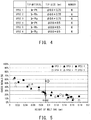
- FIG. 4 is an explanatory view showing the specs of the electrodes subjected to the thermal test.
- the precious metal tip 27 made of iridium-platinum (Ir-Pt) alloy with the content ratio of platinum being 10 wt% was used.
- the precious metal tip 27 made of iridium-rhodium (Ir-Rh) alloy with the content ratio of rhodium being 10 wt% was used.
- the precious metal tip 27 made of iridium-ruthenium (Ir-Ru) alloy with the content ratio of ruthenium being 8 wt% was used.
- the cylindrical precious metal tip 27 with the diameter of the end surface thereof being 0.6 mm and the height being 0.75 mm was used.
- the cylindrical precious metal tip 27 with the diameter of the end surface thereof being 0.8 mm and the height being 0.5 mm was used.
- each electrode subjected to the thermal test as the welding base material imitating the electrode base material 25, a cylindrical member made of INCONEL 600 (INCONEL is a registered trademark) as a nickel-base alloy was used.
- the welding base material was used in which the diameter of the end surface thereof to which the precious metal tip is to be welded was 0.3 mm larger than the diameter of the end surface of the precious metal tip to be welded.
- each electrode to be subjected to the thermal test was performed by using a pulse wave (PW) oscillation fiber laser.
- PW pulse wave
- each precious metal tip 27 was disposed on the end surface of the welding base material, and pressed and fixed by means of a pin. Then, laser welding was performed while rotating the welding base material on which the precious metal tip 27 was fixed, around the center axis O at a rotation speed of 60 rpm.
- various electrodes were manufactured with different average laser outputs ranging from 30 to 45 W.
- various electrodes were manufactured with different numbers of laser shots ranging from 11 to 14 shots. In each electrode, the irradiation time of laser per shot was 5 msec.
- the interval of laser irradiation was uniformly adjusted such that laser irradiation was finished within one rotation of the welding base material to which the precious metal tip was fixed.
- the laser irradiation was adjusted such that, in each electrode, a region irradiated with laser first time was about one-half overlapped with a region irradiated with laser last time.
- the various electrodes were manufactured with different average laser outputs and different number of laser shots, X-ray CT observation was performed on these electrodes, and the length of the melt sag 28 in each electrode in the direction of the center axis O was measured by nondestructive internal observation. While the melt sag 28 was substantially uniformly formed over the entire circumference on the side surface of the precious metal tip 27, the length of the melt sag 28 was measured at a position where the melt sag 28 has the shortest length in the direction of the center axis O.
- the first thermal test includes, as one cycle, an operation to heat the precious metal tip 27 with a burner and an operation to stop the heating, and was performed by 1,000 cycles.
- heating was performed so that the temperature of the precious metal tip 27 reached 950°C while measuring the temperature of the precious metal tip 27 with a radiation thermometer.
- the heating time per cycle was 2 minutes.
- the operation to stop the heating was one minute per cycle.
- the second thermal test is different from the first thermal test only in that the temperature of heating was 1,000°C. That is, the heating condition is stricter in the second thermal test than in the first thermal test.
- the cross section, including the center axis, of the precious metal tip 27 of each electrode was exposed. Then, in the exposed cross section, the length X1, X2 of the melt sag 28 in the direction of the center axis O was actually measured as shown in FIG. 3 . The actually measured value coincided well with the numerical value measured by the X-ray CT nondestructive internal observation.
- the exposed cross section was enlarged by 70 times and observed, and the length of the oxide scale formed at the interface between the precious metal tip 27 and the melt portion 26 was measured. Then, the ratio of the total length of the oxide scale formed between the points P9 to P10 to the length of the interface (between the points P9 and P10 in FIG.
- FIG. 5 is an explanatory view in which, regarding each electrode subjected to the first thermal test, the actually measured length (the minimum value of the distance X1, X2 in FIG. 3 ) of the melt sag 28 of the electrode in the direction of the center axis O is indicated on the horizontal axis, and the calculated oxide scale formation ratio is indicated on the vertical axis.
- the electrodes with the oxide scale formation ratios being 30% or less were evaluated as "passed”.
- the electrodes with the length of the melt sag 28 in the direction of the center axis O being 0.092 mm or more were evaluated as "passed".
- FIG. 6 is an explanatory view in which, regarding each electrode subjected to the second thermal test, the actually measured length (the minimum value of the distance X1, X2 in FIG. 3 ) of the melt sag 28 of the electrode in the direction of the center axis O is indicated on the horizontal axis, and the calculated oxide scale formation ratio is indicated on the vertical axis.
- the electrodes with the oxide scale formation ratios being 50% or less were evaluated as "passed”.
- the electrodes with the length of the melt sag 28 in the direction of the center axis O being 0.110 mm or more were evaluated as "passed".
- the present invention is not limited to the above embodiments, modes, and modifications/variations and can be embodied in various forms without departing from the scope of the present invention.
Landscapes
- Spark Plugs (AREA)
Abstract
Description
- The present invention relates to spark plugs.
- As a conventional spark plug, a spark plug has been known which includes an electrode (a center electrode or a ground electrode) to which an electrode tip (hereinafter referred to as "precious metal tip") formed of a precious metal or an alloy containing a precious metal as a main component is joined (refer to
Patent Document 1, for example). Generally, a precious metal tip is joined to an electrode base material by laser welding. Specifically, the precious metal tip is irradiated with a laser beam along its outer periphery, whereby the precious metal tip is joined to the electrode base material. When the precious metal tip is welded to the electrode base material, usually, a melt portion in which the material of the precious metal tip and the material of the electrode base material are melted is formed between the precious metal tip and the electrode base material. - As described above, in the spark plug including the precious metal tip, at an interface (hereinafter also referred to as a melt portion interface) between the melt portion and the precious metal tip, an oxide film (hereinafter also referred to as an oxide scale) may be formed on the surface of the melt portion. The oxide scale is formed, at the melt portion interface, so as to gradually grow from an outer peripheral portion near the outside air toward the inside of the melt portion interface.
- When the spark plug is used, heating and cooling cycles are repeated, whereby a stress is caused by a difference in thermal expansion coefficient between the precious metal tip and the electrode base material, near a joint portion of the precious metal tip and the electrode base material. Generally, an oxide scale is lower in strength (is more fragile) than the melt portion or the precious metal tip. Therefore, when a stress occurs as described above, crack is likely to occur in the oxide scale having the relatively low strength. When crack occurs in the oxide scale and the air enters the crack, oxidation of the melt portion interface progresses, and the oxide scale further grows toward the inside of the melt portion interface. The growth of the oxide scale toward the inside of the melt portion interface causes the crack to extend toward the inside of the melt portion interface, leading to falling off of the precious metal tip, which makes it difficult to secure reliability of the joint between the precious metal tip and the electrode base material.
- Conventionally proposed measures to improve the reliability of the joint between the precious metal tip and the electrode base material are: forming the melt portion to be thicker; and adjusting the shape of the melt portion to suppress the stress that occurs between the precious metal tip and the electrode base material (refer to
Patent Document 1, for example). Since the melt portion has an intermediate composition between the precious metal tip and the electrode base material, a difference in thermal expansion coefficient between the precious metal tip and the melt portion is smaller than the difference in thermal expansion coefficient between the precious metal tip and the electrode base material. Therefore, for example, by increasing the thickness of the melt portion, a stress that occurs near the interface between the precious metal tip and the melt portion can be suppressed, and crack is suppressed from occurring in the oxide scale due to the stress. - Patent Document 1: Japanese Patent Application Laid-Open (kokai) No.
2013-178912 - However, measures to suppress growth of the oxide scale at the interface between the precious metal tip and the electrode base material have not been sufficiently investigated. Therefore, it has been desired to suppress growth of the oxide scale and improve the reliability of the joint between the precious metal tip and the electrode base material.
- The present invention is made to solve, at least partially, the above problem, and can be embodied in the following modes.
- (1) According to one mode of the present invention, a spark plug is provided which includes an electrode obtained by welding a cylindrical precious metal tip which contains a precious metal and allows discharge at an end surface on one end side with respect to a center axis thereof, to an electrode base material disposed on the other end side, in a direction of the center axis, with respect to the precious metal tip. The electrode has a melt portion in which the precious metal tip and the electrode base material are melted, between the other end of the precious metal tip and the electrode base material. The melt portion of the spark plug includes a melt sag over an entire circumference on a side surface of the precious metal tip. Further, in this spark plug, in an arbitrary cross section, including the center axis, of the electrode: a length of a line S corresponding to the end surface on the one end side of the precious metal tip is D; two straight lines apart from the center axis by a distance of "9D/20" are virtual straight lines L1, L2, respectively; an intersection point of each virtual straight line L1, L2 and an interface between the precious metal tip and the melt portion is an intersection point P1, P2, respectively; a straight line connecting the intersection points P1 and P2 is a virtual straight line L3; of both end points of the line S, the end point located on the same side as the virtual straight line L1 with respect to the center axis is an end point P3, and the end point located on the same side as the virtual straight line L2 with respect to the center axis is an end point P4; a straight line passing each end point P3, P4 and parallel to the center axis is a virtual straight line L4, L5, respectively; of end points of the melt sag at the one end side on the virtual straight lines L4 and L5, the end point on the virtual straight line L4 is an end point P5, and the end point on the virtual straight line L5 is an end point P6; an intersection point of each virtual straight line L4, L5 and the virtual straight line L3 is an intersection point P7, P8, respectively; and each of a distance X1 between the intersection point P7 and the end point P5 and a distance X2 between the intersection point P8 and the end point P6 is 0.092 mm or more. According to the spark plug of this mode, since the melt sag having a predetermined shape is formed over the entire circumference on the side surface of the precious metal tip, entry of the air into the interface between the precious metal tip and the melt portion can be suppressed, thereby suppressing formation of an oxide scale at the interface between the precious metal tip and the melt portion. As a result, when the heating and cooling cycles are repeated in the spark plug, it is possible to suppress occurrence of crack due to a difference in thermal expansion coefficient between the precious metal tip and the electrode base material at the interface between the precious metal tip and the melt portion, whereby reliability of the joint between the precious metal tip and the electrode base material can be improved.
- (2) In the spark plug according to the above mode, each of the distances X1 and X2 may be 0.110 mm or more. According to the spark plug of this mode, growth of the oxide scale at the interface between the precious metal tip and the melt portion is more suppressed, whereby reliability of the joint between the precious metal tip and the electrode base material can be further improved.
- The present invention can be embodied in various forms other than the spark plug. For example, the present invention can be embodied in forms of an internal combustion engine on which the spark plug is mounted, a vehicle including the internal combustion engine, and the like. Further, the present invention can be embodied in the form of a method for manufacturing the spark plug.
-
- [
FIG. 1 ] Partially cross-sectional view of a spark plug. - [
FIG. 2 ] Enlarged explanatory view showing the structure of a front end portion of a center electrode. - [
FIG. 3 ] Cross-sectional view for explaining the specific shape of a melt sag. - [
FIG. 4 ] Explanatory view showing specs of electrodes subjected to a thermal test. - [
FIG. 5 ] Explanatory view having a horizontal axis indicating the length of the melt sag, and a vertical axis indicating the oxide scale formation ratio. - [
FIG. 6 ] Explanatory view having a horizontal axis indicating the length of the melt sag, and a vertical axis indicating the oxide scale formation ratio. -
FIG. 1 is a partially cross-sectional view of aspark plug 100 as an embodiment of the present invention. Thespark plug 100 has an elongated shape extending along an axis Ax (a center axis of the spark plug 100). InFIG. 1 , the right side of the axis Ax indicated by a dot-dash line shows an exterior front view, and the left side of the axis Ax shows a sectional view where thespark plug 100 is sectioned by a plane that passes the axis Ax. In the following description, in a direction parallel to the axis Ax, the lower side inFIG. 1 (indicated by an arrow X inFIG. 1 ) is referred to as the front side, and the upper side inFIG. 1 is referred to as the rear side. - The
spark plug 100 includes aceramic insulator 10, acenter electrode 20, aground electrode 30, ametal terminal 40, and ametallic shell 50. The rod-shaped center electrode 20 projecting from a front end of theceramic insulator 10 extends through the interior of theceramic insulator 10 and is electrically connected to themetal terminal 40 provided at a rear end of theceramic insulator 10. The outer periphery of thecenter electrode 20 is held by theceramic insulator 10, and the outer periphery of theceramic insulator 10 is held by themetallic shell 50 at a position apart from themetal terminal 40. - The
ground electrode 30 electrically connected to themetallic shell 50 forms a spark gap which is a gap for generating a spark, between theground electrode 30 and the front end of thecenter electrode 20. Thespark plug 100 is attached, through themetallic shell 50, to a threadedattachment hole 201 provided in anengine head 200 of an internal combustion engine. When a high voltage of 20,000 to 30,000 V is applied to themetal terminal 40, a spark is generated at the spark gap formed between thecenter electrode 20 and theground electrode 30. - The
ceramic insulator 10 is an insulator formed through firing of a ceramic material such as alumina. Theceramic insulator 10 is a cylindrical member having, in the center thereof, anaxial hole 12 in which thecenter electrode 20 and themetal terminal 40 are accommodated. Theceramic insulator 10 has acentral trunk portion 19 formed at the center thereof in the axial direction and having an increased outer diameter. Arear trunk portion 18 for insulation between themetal terminal 40 and themetallic shell 50 is formed on themetal terminal 40 side relative to thecentral trunk portion 19. Afront trunk portion 17 having an outer diameter smaller than that of therear trunk portion 18 is formed on thecenter electrode 20 side relative to thecentral trunk portion 19. Aleg portion 13 having an outer diameter which is smaller than that of thefront trunk portion 17 and decreases toward the front side is formed frontward of thefront trunk portion 17. - The
metallic shell 50 is a cylindrical metallic member that surrounds a portion of theceramic insulator 10 extending from a part of therear trunk portion 18 to theleg portion 13 to hold theceramic insulator 10. In the present embodiment, themetallic shell 50 is formed of low carbon steel, and the entirety of themetallic shell 50 is subjected to plating such as nickel plating or zinc plating. Themetallic shell 50 has atool engagement portion 51, a threadedattachment portion 52, and agasket receiving portion 54. - A tool (not shown) used for fixing the
spark plug 100 to anengine head 200 is engaged with thetool engagement portion 51 of themetallic shell 50. The threadedattachment portion 52 of themetallic shell 50 has a screw thread to be screwed into the threadedattachment hole 201 of theengine head 200. Thegasket receiving portion 54 of themetallic shell 50 projects radially outward relative to the threadedattachment portion 52 and is formed in a flange shape, on the rear side of the threadedattachment portion 52. - In addition, a
gasket 5 which is a substantially annular-shaped solid member is fitted to themetallic shell 50 so as to be in contact with a front-side end portion of thegasket receiving portion 54. Thegasket 5 secures sufficient seal between thegasket receiving portion 54 of thespark plug 100 and theengine head 200. Afront end surface 57 of themetallic shell 50 is formed in a circular shape having an opening in a center portion thereof. At the center portion, thecenter electrode 20 projects from theleg portion 13 of theceramic insulator 10. - A
thin crimp portion 53 is provided on the rear side of themetallic shell 50 with respect to thetool engagement portion 51. In addition, acompressive deformation portion 58, as thin as thecrimp portion 53, is provided between thegasket receiving portion 54 and thetool engagement portion 51.Annular ring members metallic shell 50 from thetool engagement portion 51 to thecrimp portion 53, and an outer peripheral surface of therear trunk portion 18 of theceramic insulator 10. Further, powder oftalc 9 is charged between thering members - When the
spark plug 100 is manufactured, crimping is performed in which thecrimp portion 53 is bent inward and pressed frontward, whereby thecompressive deformation portion 58 is compressed and deformed. As a result of the crimping, theceramic insulator 10 is pressed frontward in themetallic shell 50 through thering members talc 9. As a result of this pressing, thetalc 9 is compressed in the direction of the axis Ax, whereby the airtightness of themetallic shell 50 is improved. - At the inner periphery of the
metallic shell 50, aceramic step portion 15 located at a base end of theleg portion 13 of theceramic insulator 10 is pressed, through a ring-shaped sheet packing 8, against a metal-shellinternal step portion 56 formed at the position of the threadedattachment portion 52. The sheet packing 8 is a member for maintaining airtightness between themetallic shell 50 and theceramic insulator 10, and prevents combustion gas from flowing out. - The
center electrode 20 includes anelectrode base material 25 which is a rod-shaped member extending in the direction of the axis Ax. Theelectrode base material 25 is formed of a nickel alloy containing nickel as a main component. In the present embodiment, theelectrode base material 25 has, therein, a core member formed of a material having higher thermal conductivity than theelectrode base material 25, such as copper or an alloy containing copper as a main component. Thecenter electrode 20 according to the present embodiment further includes, at a front end of theelectrode base material 25, a precious metal tip for improving resistance to spark-induced erosion and resistance to oxidation-induced erosion. The structure of the front end portion of thecenter electrode 20 will be described later in detail. Thecenter electrode 20 is inserted in theaxial hole 12 of theceramic insulator 10, with the front end of theelectrode base material 25 projecting from theaxial hole 12 of theceramic insulator 10, and is electrically connected to themetal terminal 40 through aceramic resistor 3 and aseal body 4. - The
ground electrode 30 is a rod-shaped member, and has a base end welded to thefront end surface 57 of themetallic shell 50. The front side of theground electrode 30 is bent in a direction intersecting the axis Ax, and the front end portion of theground electrode 30 faces the front end surface of thecenter electrode 20 on the axis Ax. A precious metal tip similar to thecenter electrode 20 may be provided at a position opposed to thecenter electrode 20 at the front end portion of theground electrode 30. -
FIG. 2 is an enlarged explanatory view showing the structure of the front end portion of thecenter electrode 20.FIG. 2(A) is a side view showing the appearance of the front end portion of thecenter electrode 20, andFIG. 2(B) is a cross-sectional view showing a cross section including a center axis O of aprecious metal tip 27 included in thecenter electrode 20. InFIG. 2(A) , the above-described front side of thespark plug 100 is indicated by an arrow X. In thespark plug 100 according to the present embodiment, the center axis O of theprecious metal tip 27 coincides with the axis Ax as the center axis of thespark plug 100. - The
precious metal tip 27 is a cylindrical member formed of a precious metal (e.g., platinum, iridium, ruthenium, rhodium, or the like) or an alloy containing not less than 50 wt% of a precious metal as a main component, and is joined to the front end surface of theelectrode base material 25 by laser welding. Therefore, amelt portion 26 in which theelectrode base material 25 and theprecious metal tip 27 are melted is formed between the front end surface of theelectrode base material 25 and theprecious metal tip 27. In the present embodiment, themelt portion 26 is formed so as to cover the entire front end surface of theelectrode base material 25. - In the
precious metal tip 27 welded to theelectrode base material 25, the diameter of the cross section perpendicular to the center axis O (the diameter of the end surface on the front side) can be, for example, 0.3 mm or more, and preferably 0.4 mm or more. In addition, the diameter of the cross section of theprecious metal tip 27 can be, for example, 1.5 mm or less, and preferably 1.2 mm or less. In addition, in theelectrode base material 25, the front end surface to which theprecious metal tip 27 is joined may have a size enough to be in contact with the entire rear end surface of theprecious metal tip 27. For example, when theelectrode base material 25 is a cylindrical member, the diameter of the front end surface of theelectrode base material 25 may be about 0.2 to 0.4 mm larger than the diameter of the rear end surface of theprecious metal tip 27, in terms of facilitating welding. - Further, in the present embodiment, a
melt sag 28 is formed in themelt portion 26. When theelectrode base material 25 and theprecious metal tip 27 are melted and thereby themelt portion 26 is formed, themelt sag 28 is formed as a portion of a melt forming themelt portion 26. That is, themelt sag 28 is formed such that a portion of the melt extends frontward along the side surface of theprecious metal tip 27, from near the interface between theelectrode base material 25 and theprecious metal tip 27, when theelectrode base material 25 and theprecious metal tip 27 are welded (refer toFIG. 2(B) ). In the present embodiment, themelt sag 28 is formed over the entire circumference on the side surface of theprecious metal tip 27. - Welding of the
electrode base material 25 and theprecious metal tip 27 may be performed by bringing the front end surface of theelectrode base material 25 into contact with the rear end surface of theprecious metal tip 27, and irradiating an area including the contact portions thereof, with a laser beam, from the outer peripheral side of theprecious metal tip 27 toward the inside thereof. In the present embodiment, the irradiation with the laser beam is performed from the outer peripheral side of theprecious metal tip 27 toward the center axis O of theprecious metal tip 27. It is desirable that the irradiation with the laser beam is uniformly performed over the entire circumference of theprecious metal tip 27. - Welding of the
electrode base material 25 and theprecious metal tip 27 may employ various devices capable of emitting laser beams, such as a YAG laser, a carbon dioxide gas laser, a semiconductor laser, and a fiber laser. The employed laser may be a pulse wave (PW) oscillation laser or a continuous wave (CW) oscillation laser. In welding, in order to form themelt sag 28 having a desired shape described later, for example, it is desirable that the amount of energy per irradiation width is increased in a profile of the laser beam. In order to increase the amount of energy per irradiation width in the profile of the laser beam, for example, a lens or an oscillator in the laser irradiation device may be optimized, and a condition selected from the laser output and the laser irradiation time may be adjusted. In particular, it is desirable to use a fiber laser in terms of increasing the amount of energy per irradiation width. -
FIG. 3 is a cross-sectional view for explaining a specific shape of themelt sag 28.FIG. 3 shows a cross section, including the center axis O, of the front end portion of thecenter electrode 20. InFIG. 3 , a line corresponding to a front-side end surface of theprecious metal tip 27 is indicated as a line S, and the line S has a length D. Themelt sag 28 formed in thecenter electrode 20 according to the present embodiment has a shape as follows. - In the cross section shown in
FIG. 3 , two straight lines apart from the center axis O by a distance of "9D/20" are referred to as virtual straight lines L1 and L2, respectively. An intersection of the virtual straight line L1, L2 and the interface between theprecious metal tip 27 and themelt portion 26 is referred to as an intersection point P1, P2, respectively. A straight line connecting the intersection points P1 and P2 is referred to as a straight line L3. - Of both end points of the line S, the end point positioned on the same side as the virtual straight line L1 with respect to the center axis O is referred to as an end point P3, and the end point positioned on the same side as the virtual straight line L2 with respect to the center axis O is referred to as an end point P4. A straight line which passes the end point P3, P4 and is parallel to the center axis O is referred to as a virtual straight line L4, L5, respectively. Of end points at the front side of the
melt sag 28 on the virtual straight lines L4 and L5, the end point on the virtual straight line L4 is referred to as an end point P5, and the end point on the virtual straight line L5 is referred to as an end point P6. An intersection point of the virtual straight line L4, L5 and the virtual straight line L3 is referred to as an intersection point P7, P8, respectively. At this time, a distance X1 between the intersection point P7 and the end point P5 and a distance X2 between the intersection point P8 and the end point P6 are each 0.092 mm or more. - Further, in the cross section shown in
FIG. 3 , at the interface between theprecious metal tip 27 and themelt portion 26, a rear end of a portion overlapping the virtual straight line L4 is referred to as a point P9, and a rear end of a portion overlapping the virtual straight line L5 is referred to as a point P10. Regarding an area where theprecious metal tip 27 and themelt portion 26 are in contact with each other, an area between the points P5 and P9 and an area between the points P6 and P10 each are an area where the surface of theprecious metal tip 27 is not substantially melted. In contrast, in the area where theprecious metal tip 27 and themelt portion 26 are in contact with each other, an area between the points P9 and P10 is an area where the surface of theprecious metal tip 27 is melted. Therefore, in the specification of the present application, in the area where theprecious metal tip 27 and themelt portion 26 are in contact with each other, the area between the points P9 and P10 is also referred to as an "interface between theprecious metal tip 27 and themelt portion 26". The interface indicated by P9-P10 where the surface of theprecious metal tip 27 is melted is an area which significantly contributes to the joint strength between theprecious metal tip 27 and theelectrode base material 25. - In the
spark plug 100 according to the present embodiment, the shape of themelt sag 28 described with reference toFIG. 3 is obtained at any cross section, including the center axis O, of the front end portion of thecenter electrode 20. - According to the
spark plug 100 of the present embodiment configured as described above, themelt sag 28, which is a part of themelt portion 26 extending frontward, is formed on the side surface of theprecious metal tip 27 disposed at the front end portion of thecenter electrode 20. Therefore, entry of the air into the interface between theprecious metal tip 27 and themelt portion 26 can be suppressed, thereby suppressing formation of the oxide scale that is lower in strength than theprecious metal tip 27 and themelt portion 26, at the interface between theprecious metal tip 27 and themelt portion 26. As a result, when the heating and cooling cycles are repeated in thespark plug 100, it is possible to suppress occurrence of crack due to a difference in thermal expansion coefficient between theprecious metal tip 27 and theelectrode base material 25 at the interface between theprecious metal tip 27 and themelt portion 26. By suppressing occurrence of crack, entry of the air into the interface between theprecious metal tip 27 and themelt portion 26 is suppressed, whereby further growth of the oxide scale can be suppressed. By suppressing extension of crack in this way, falling off of theprecious metal tip 27 is suppressed, whereby reliability of the joint between theprecious metal tip 27 and theelectrode base material 25 can be improved. - That is, it is conceivable that the
melt sag 28 has a function as a seal portion which suppresses entry of the air into the interface between theprecious metal tip 27 and themelt portion 26. Therefore, by forming themelt sag 28 to be long along the center axis O, the effect of suppressing growth of the oxide scale and extension of crack at the interface between theprecious metal tip 27 and themelt portion 26 can be improved. - In particular, in the present embodiment, the condition that the length (corresponding to the distance X1, X2 in
FIG. 3 ) of themelt sag 28 from a predetermined reference position corresponding to the virtual straight line L3 shown inFIG. 3 along the direction of the center axis O is 0.092 mm or more, is satisfied over the entire circumference on the side surface of theprecious metal tip 27. Therefore, growth of the oxide scale can be effectively suppressed over the entire interface between theprecious metal tip 27 and themelt portion 26. - As described above, according to the present embodiment, the melt sag, which has been considered to be undesirable in terms of appearance, is intentionally formed to a predetermined length or more, whereby reliability of the joint of the
precious metal tip 27 is improved, resulting in increase in durability of thespark plug 100. - The larger the length of the
melt sag 28 in the direction of the center axis O is, the more the effect of suppressing growth of the oxide scale at the interface between theprecious metal tip 27 and themelt portion 26 can be improved. It is particularly desirable that the length of the melt sag 28 (the distance X1, X2 inFIG. 3 ) is 0.110 mm or more. With such a configuration, even when the temperature at which theprecious metal tip 27 is exposed is high in the heating and cooling cycles, reliability of the joint between the precious metal tip and the electrode base material can be secured. However, the upper limit of the length of the melt sag 28 (the distance X1, X2 inFIG. 3 ) is preferably equal to the distance between the virtual straight line L3 and the point P3, P4 which is the end point of the line S corresponding to the front-side end surface of theprecious metal tip 27. In other words, it is desirable that themelt sag 28 is not present on the front-side end surface of theprecious metal tip 27. The cause of this is to suppress themelt sag 28 from adversely affecting ignitability in thespark plug 100. - The above-described length of the
melt sag 28 is the length for securing the function thereof as the seal portion that suppresses entry of the air into the interface between theprecious metal tip 27 and themelt portion 26. Therefore, the effect achieved by setting the length of themelt sag 28 in the direction of the center axis O to the above-described value is the effect achieved regardless of the size of theprecious metal tip 27 and the material of theprecious metal tip 27. - In the present embodiment, the virtual straight line L3 is a position to be a reference for specifying the length, in the direction of the center axis O, of the
melt sag 28 formed on the side surface of theprecious metal tip 27. The virtual straight line L3 is specified as follows. - As already described, the effect obtained by providing the
melt sag 28 is achieved when themelt sag 28 covers the side surface of theprecious metal tip 27 to suppress entry of the air into the interface between theprecious metal tip 27 and themelt portion 26. Therefore, it is considered that the reference that defines the length of themelt sag 28 should be determined on the basis of the position of the interface between theprecious metal tip 27 and themelt portion 26 at the rear-side end portion of theprecious metal tip 27. However, the shape of the interface between theprecious metal tip 27 and themelt portion 26 can vary depending on the welding condition. In particular, in the case where themelt sag 28 is provided on the side surface of theprecious metal tip 27 as in the present embodiment, when the high-temperature melt formed of theprecious metal tip 27 and theelectrode base material 25 being melted extends frontward on the side surface of theprecious metal tip 27, the side surface of theprecious metal tip 27 is melted to some degree by being in contact with the melt. The degree of the melting of the side surface of theprecious metal tip 27 is greater in the position closer to the rear side where the high-temperature melt is supplied. The distance of "9D/20" from the center axis O, which defines the virtual straight line L1, L2 used for obtaining the virtual straight line L3 in the present embodiment is a value experientially obtained by the inventors of the present application, as a position at which influence of the melting of the side surface of theprecious metal tip 27 due to the high-temperature melt is sufficiently reduced. In the present embodiment, the virtual straight line L3 to be the reference is obtained by connecting the intersection points P1 and P2 which are the intersection points of the virtual straight lines L1 and L2 each apart from the center axis O by the distance of "9D/20" and the interface between theprecious metal tip 27 and themelt portion 26, respectively. Thus, the length, in the direction of the center axis O, of themelt sag 28 formed on the side surface of theprecious metal tip 27 is specified by determining the position of the rear-side end portion on the side surface of theprecious metal tip 27 while suppressing influence of the melted and deformed side surface of theprecious metal tip 27 due to the high-temperature melt. - In the above embodiment, when the
precious metal tip 27 is welded, the entire circumference of theprecious metal tip 27 is uniformly irradiated with the laser beam, whereby the length of themelt sag 28 in the direction of the center axis O is almost uniform over the entire circumference of the side surface of theprecious metal tip 27. However, another configuration may be adopted. The length of themelt sag 28 in the direction of the center axis O may be non-uniform. For example, in the cross section shown inFIG. 3 , the distance X1 and the distance X2 may be different from each other. In all the cross sections of theprecious metal tip 27 including the center axis O, the length (the distance X1, X2 inFIG. 3 ) of themelt sag 28 described with reference toFIG. 3 may be 0.092 mm or more. In addition, the center electrode 120 may have a portion in which theprecious metal tip 27 and theelectrode base material 25 are in direct contact with each other without the melt portion 126 intervening therebetween. Even in such a configuration, the same effect as in the above embodiment can be achieved as long as themelt sag 28 of the melt portion 126 has the same length, in the direction of the center axis O, as the length in the above embodiment. - Welding of the
precious metal tip 27 and theelectrode base material 25 may be performed by other welding methods than the above-described laser welding, such as electron beam welding. In this case, as long as the electron beam welding is capable of melting theprecious metal tip 27 and theelectrode base material 25 by irradiating theprecious metal tip 27 with an energy beam, from the outer peripheral side thereof toward the inside thereof, and welding them together to form themelt portion 26 having themelt sag 28, the present invention can be applied to the electron beam welding as in the above embodiment. - In the above embodiment, the length, in the direction of the center axis O, of the
melt sag 28 formed by welding theprecious metal tip 27 to theelectrode base material 25 of thecenter electrode 20 is defined. However, another configuration may be adopted. The present invention may be applied to theground electrode 30 instead of or in addition to thecenter electrode 20. - Various
precious metal tips 27 having different components and sizes were welded to theelectrode base material 25, thereby manufacturing a plurality of electrodes having different lengths of themelt sag 28 in the direction of the center axis O. A thermal test was performed to expose these electrodes to heating and cooling cycles, and the degree of the oxide scale formed at the interface between eachprecious metal tip 27 and themelt portion 26 was examined. Regarding the thermal test, two types of tests (a first thermal test and a second thermal test) having different heating conditions were performed. The thermal test was performed as a desk test in which the precious metal tips were welded onto a welding base material imitating theelectrode base material 25 and heated by using a burner, instead of actually fabricating a spark plug and actually performing ignition operation using the spark plug. -
FIG. 4 is an explanatory view showing the specs of the electrodes subjected to the thermal test. In the electrodes according toSpec 1 andSpec 4, theprecious metal tip 27 made of iridium-platinum (Ir-Pt) alloy with the content ratio of platinum being 10 wt% was used. In the electrodes according toSpec 2 andSpec 5, theprecious metal tip 27 made of iridium-rhodium (Ir-Rh) alloy with the content ratio of rhodium being 10 wt% was used. In the electrodes according toSpec 3 andSpec 6, theprecious metal tip 27 made of iridium-ruthenium (Ir-Ru) alloy with the content ratio of ruthenium being 8 wt% was used. In addition, in the electrodes according toSpec 1 toSpec 3, the cylindricalprecious metal tip 27 with the diameter of the end surface thereof being 0.6 mm and the height being 0.75 mm was used. In the electrodes according toSpec 4 toSpec 6, the cylindricalprecious metal tip 27 with the diameter of the end surface thereof being 0.8 mm and the height being 0.5 mm was used. - In each electrode subjected to the thermal test, as the welding base material imitating the
electrode base material 25, a cylindrical member made of INCONEL 600 (INCONEL is a registered trademark) as a nickel-base alloy was used. In manufacturing each electrode, the welding base material was used in which the diameter of the end surface thereof to which the precious metal tip is to be welded was 0.3 mm larger than the diameter of the end surface of the precious metal tip to be welded. - The welding conditions in manufacturing each electrode to be subjected to the thermal test are as follows. Welding was performed by using a pulse wave (PW) oscillation fiber laser. In advance of laser welding, each
precious metal tip 27 was disposed on the end surface of the welding base material, and pressed and fixed by means of a pin. Then, laser welding was performed while rotating the welding base material on which theprecious metal tip 27 was fixed, around the center axis O at a rotation speed of 60 rpm. For each spec, various electrodes were manufactured with different average laser outputs ranging from 30 to 45 W. In addition, for each spec, various electrodes were manufactured with different numbers of laser shots ranging from 11 to 14 shots. In each electrode, the irradiation time of laser per shot was 5 msec. The interval of laser irradiation was uniformly adjusted such that laser irradiation was finished within one rotation of the welding base material to which the precious metal tip was fixed. The laser irradiation was adjusted such that, in each electrode, a region irradiated with laser first time was about one-half overlapped with a region irradiated with laser last time. - Thus, for each spec, the various electrodes were manufactured with different average laser outputs and different number of laser shots, X-ray CT observation was performed on these electrodes, and the length of the
melt sag 28 in each electrode in the direction of the center axis O was measured by nondestructive internal observation. While themelt sag 28 was substantially uniformly formed over the entire circumference on the side surface of theprecious metal tip 27, the length of themelt sag 28 was measured at a position where themelt sag 28 has the shortest length in the direction of the center axis O. Then, for each of the first thermal test and the second thermal test, six electrodes having different welding conditions were selected for each spec in such a manner that the length of themelt sag 28 in the direction of the center axis O varied as uniformly as possible among the six electrodes within a range from about 0.01 mm to about 0.18 mm (inFIG. 4 , for each spec, the number of electrodes is 6). - All the electrodes, which were selected by six for each of
Spec 1 toSpec 6 as described above, were subjected to the first thermal test. The first thermal test includes, as one cycle, an operation to heat theprecious metal tip 27 with a burner and an operation to stop the heating, and was performed by 1,000 cycles. In the heating operation, heating was performed so that the temperature of theprecious metal tip 27 reached 950°C while measuring the temperature of theprecious metal tip 27 with a radiation thermometer. The heating time per cycle was 2 minutes. The operation to stop the heating was one minute per cycle. - All the electrodes, which were selected by six for each of
Spec 1 toSpec 6 as described above, were subjected to the second thermal test. The second thermal test is different from the first thermal test only in that the temperature of heating was 1,000°C. That is, the heating condition is stricter in the second thermal test than in the first thermal test. - After the first and second thermal tests were executed each by 1,000 cycles, the cross section, including the center axis, of the
precious metal tip 27 of each electrode was exposed. Then, in the exposed cross section, the length X1, X2 of themelt sag 28 in the direction of the center axis O was actually measured as shown inFIG. 3 . The actually measured value coincided well with the numerical value measured by the X-ray CT nondestructive internal observation. The exposed cross section was enlarged by 70 times and observed, and the length of the oxide scale formed at the interface between theprecious metal tip 27 and themelt portion 26 was measured. Then, the ratio of the total length of the oxide scale formed between the points P9 to P10 to the length of the interface (between the points P9 and P10 inFIG. 3 ) between theprecious metal tip 27 and themelt portion 26 was calculated as an oxide scale formation ratio. At the interface between theprecious metal tip 27 and themelt portion 26 exposed at the cross section of the electrode, the color of the oxide scale is different in color from other portions and therefore can be easily distinguished. -
FIG. 5 is an explanatory view in which, regarding each electrode subjected to the first thermal test, the actually measured length (the minimum value of the distance X1, X2 inFIG. 3 ) of themelt sag 28 of the electrode in the direction of the center axis O is indicated on the horizontal axis, and the calculated oxide scale formation ratio is indicated on the vertical axis. In the first thermal test, the electrodes with the oxide scale formation ratios being 30% or less were evaluated as "passed". As shown inFIG. 5 , in each spec, the electrodes with the length of themelt sag 28 in the direction of the center axis O being 0.092 mm or more were evaluated as "passed". Therefore, it was confirmed that the effect of suppressing growth of the oxide scale was improved by setting the length of themelt sag 28 to be 0.092 mm or more. No difference was observed in the above tendency among the specs of theprecious metal tip 27, i.e., among the different components and sizes of theprecious metal tip 27. -
FIG. 6 is an explanatory view in which, regarding each electrode subjected to the second thermal test, the actually measured length (the minimum value of the distance X1, X2 inFIG. 3 ) of themelt sag 28 of the electrode in the direction of the center axis O is indicated on the horizontal axis, and the calculated oxide scale formation ratio is indicated on the vertical axis. In the second thermal test, the electrodes with the oxide scale formation ratios being 50% or less were evaluated as "passed". As shown inFIG. 6 , in each spec, the electrodes with the length of themelt sag 28 in the direction of the center axis O being 0.110 mm or more were evaluated as "passed". Therefore, it was confirmed that, even when the electrodes were subjected to severe heating and cooling cycles with the heating temperature reaching 1000°C, the effect of suppressing growth of the oxide scale was improved by setting the length of themelt sag 28 to be 0.110 mm or more. No difference was observed in the above tendency among the specs of theprecious metal tip 27, i.e., among the different components and sizes of theprecious metal tip 27. - The present invention is not limited to the above embodiments, modes, and modifications/variations and can be embodied in various forms without departing from the scope of the present invention. For example, it is feasible to appropriately replace or combine any of the technical features of the aspects of the present invention described in "Summary of the Invention" and the technical features of the embodiments, modes, and modifications/variations of the present invention in order to solve part or all of the above-mentioned problems or achieve part or all of the above-mentioned effects. Any of these technical features, if not explained as essential in the present specification, may be deleted as appropriate.
-
- 3 ···
- ceramic resistor
- 4 ···
- seal body
- 5 ···
- gasket
- 6 ···
- ring member
- 8 ···
- sheet packing
- 9 ···
- talc
- 10 ···
- ceramic insulator
- 12 ···
- axial hole
- 13 ···
- leg portion
- 15 ···
- ceramic step portion
- 17 ···
- front trunk portion
- 18 ···
- rear trunk portion
- 19 ···
- central trunk portion
- 20, 120 ···
- center electrode
- 25 ···
- electrode base material
- 26, 126 ···
- melt portion
- 27 ···
- precious metal tip
- 28 ···
- melt sag
- 30 ···
- ground electrode
- 40 ···
- metal terminal
- 50 ···
- metallic shell
- 51 ···
- tool engagement portion
- 52 ···
- threaded attachment portion
- 53 ···
- crimp portion
- 54 ···
- gasket receiving portion
- 56 ···
- metal-shell internal step portion
- 57 ···
- front end surface
- 58 ···
- compressive deformation portion
- 100 ···
- spark plug
- 200 ···
- engine head
- 201 ···
- threaded attachment hole
- 600 ···
- INCONEL
Claims (2)
- A spark plug including an electrode obtained by welding a cylindrical precious metal tip which contains a precious metal and allows discharge at an end surface on one end side with respect to a center axis thereof, to an electrode base material disposed on the other end side, in a direction of the center axis, with respect to the precious metal tip, the electrode having a melt portion in which the precious metal tip and the electrode base material are melted, between the other end of the precious metal tip and the electrode base material, wherein
the melt portion includes a melt sag over an entire circumference on a side surface of the precious metal tip, and
in an arbitrary cross section, including the center axis, of the electrode,
a length of a line S corresponding to the end surface on the one end side of the precious metal tip is D,
two straight lines apart from the center axis by a distance of "9D/20" are virtual straight lines L1, L2, respectively,
an intersection point of each virtual straight line L1, L2 and an interface between the precious metal tip and the melt portion is an intersection point P1, P2, respectively,
a straight line connecting the intersection points P1 and P2 is a virtual straight line L3,
of both end points of the line S, the end point located on the same side as the virtual straight line L1 with respect to the center axis is an end point P3, and the end point located on the same side as the virtual straight line L2 with respect to the center axis is an end point P4,
a straight line passing each end point P3, P4 and parallel to the center axis is a virtual straight line L4, L5, respectively,
of end points of the melt sag at the one end side on the virtual straight lines L4 and L5, the end point on the virtual straight line L4 is an end point P5, and the end point on the virtual straight line L5 is an end point P6,
an intersection point of each virtual straight line L4, L5 and the virtual straight line L3 is an intersection point P7, P8, respectively, and
each of a distance X1 between the intersection point P7 and the end point P5 and a distance X2 between the intersection point P8 and the end point P6 is 0.092 mm or more. - The spark plug according to claim 1, wherein each of the distances X1 and X2 is 0.110 mm or more.
Applications Claiming Priority (2)
| Application Number | Priority Date | Filing Date | Title |
|---|---|---|---|
| JP2014133806A JP5914582B2 (en) | 2014-06-30 | 2014-06-30 | Spark plug |
| PCT/JP2015/002984 WO2016002143A1 (en) | 2014-06-30 | 2015-06-15 | Spark plug |
Publications (3)
| Publication Number | Publication Date |
|---|---|
| EP3163693A1 true EP3163693A1 (en) | 2017-05-03 |
| EP3163693A4 EP3163693A4 (en) | 2018-02-28 |
| EP3163693B1 EP3163693B1 (en) | 2020-08-19 |
Family
ID=55018724
Family Applications (1)
| Application Number | Title | Priority Date | Filing Date |
|---|---|---|---|
| EP15814683.7A Active EP3163693B1 (en) | 2014-06-30 | 2015-06-15 | Spark plug |
Country Status (6)
| Country | Link |
|---|---|
| US (1) | US9837799B2 (en) |
| EP (1) | EP3163693B1 (en) |
| JP (1) | JP5914582B2 (en) |
| KR (1) | KR101915376B1 (en) |
| CN (1) | CN106663920B (en) |
| WO (1) | WO2016002143A1 (en) |
Families Citing this family (6)
| Publication number | Priority date | Publication date | Assignee | Title |
|---|---|---|---|---|
| JP6427133B2 (en) * | 2016-03-29 | 2018-11-21 | 日本特殊陶業株式会社 | Spark plug |
| JP6715276B2 (en) * | 2018-03-13 | 2020-07-01 | 日本特殊陶業株式会社 | Spark plug |
| JP6731450B2 (en) * | 2018-07-11 | 2020-07-29 | 日本特殊陶業株式会社 | Spark plug |
| JP7027354B2 (en) * | 2019-01-25 | 2022-03-01 | 日本特殊陶業株式会社 | Spark plug |
| JP7126961B2 (en) * | 2019-01-25 | 2022-08-29 | 日本特殊陶業株式会社 | spark plug |
| JP2021082539A (en) | 2019-11-21 | 2021-05-27 | 株式会社デンソー | Spark plug, and center electrode manufacturing method |
Family Cites Families (7)
| Publication number | Priority date | Publication date | Assignee | Title |
|---|---|---|---|---|
| JP5058114B2 (en) * | 2008-09-30 | 2012-10-24 | 日本特殊陶業株式会社 | Spark plug and method for manufacturing the spark plug. |
| WO2012042801A1 (en) * | 2010-09-29 | 2012-04-05 | 日本特殊陶業株式会社 | Spark plug |
| JP5302944B2 (en) * | 2010-11-04 | 2013-10-02 | 日本特殊陶業株式会社 | Spark plug and manufacturing method thereof |
| JP5835704B2 (en) * | 2011-08-03 | 2015-12-24 | 日本特殊陶業株式会社 | Spark plug |
| JP5942473B2 (en) | 2012-02-28 | 2016-06-29 | 株式会社デンソー | Spark plug for internal combustion engine and method for manufacturing the same |
| JP5820323B2 (en) * | 2012-03-29 | 2015-11-24 | 日本特殊陶業株式会社 | Manufacturing method of spark plug |
| JP5653399B2 (en) * | 2012-08-30 | 2015-01-14 | 日本特殊陶業株式会社 | Spark plug |
-
2014
- 2014-06-30 JP JP2014133806A patent/JP5914582B2/en active Active
-
2015
- 2015-06-15 US US15/317,596 patent/US9837799B2/en active Active
- 2015-06-15 CN CN201580034878.XA patent/CN106663920B/en active Active
- 2015-06-15 EP EP15814683.7A patent/EP3163693B1/en active Active
- 2015-06-15 WO PCT/JP2015/002984 patent/WO2016002143A1/en not_active Ceased
- 2015-06-15 KR KR1020167036106A patent/KR101915376B1/en not_active Expired - Fee Related
Also Published As
| Publication number | Publication date |
|---|---|
| US20170125981A1 (en) | 2017-05-04 |
| KR101915376B1 (en) | 2018-11-05 |
| CN106663920B (en) | 2018-03-30 |
| JP2016012479A (en) | 2016-01-21 |
| US9837799B2 (en) | 2017-12-05 |
| WO2016002143A1 (en) | 2016-01-07 |
| EP3163693B1 (en) | 2020-08-19 |
| KR20170008857A (en) | 2017-01-24 |
| JP5914582B2 (en) | 2016-05-11 |
| CN106663920A (en) | 2017-05-10 |
| EP3163693A4 (en) | 2018-02-28 |
Similar Documents
| Publication | Publication Date | Title |
|---|---|---|
| EP3163693B1 (en) | Spark plug | |
| JP6205006B2 (en) | Spark plug | |
| EP2624384B1 (en) | Spark plug | |
| US9236715B2 (en) | Spark plug and method of manufacturing spark plug | |
| JP5475906B2 (en) | Manufacturing method of spark plug | |
| US20170033540A1 (en) | Spark plug | |
| US8692447B2 (en) | Spark plug for internal combustion engine and manufacturing method thereof | |
| EP2560255B1 (en) | Spark plug for internal combustion engine and method of manufacturing spark plug | |
| JP5449578B2 (en) | Spark plug | |
| US10283941B2 (en) | Spark plug | |
| JP2010272212A (en) | Spark plug | |
| JP2009134968A (en) | Spark plug for internal combustion engine | |
| US10868409B2 (en) | Spark plug | |
| JP6347818B2 (en) | Spark plug | |
| JP5576753B2 (en) | Manufacturing method of spark plug | |
| US9716370B2 (en) | Spark plug | |
| US9160146B2 (en) | Spark plug | |
| JP2013118082A (en) | Spark plug and spark plug manufacturing method | |
| US20180351331A1 (en) | Spark plug | |
| JP2017134921A (en) | Spark plug |
Legal Events
| Date | Code | Title | Description |
|---|---|---|---|
| STAA | Information on the status of an ep patent application or granted ep patent |
Free format text: STATUS: THE INTERNATIONAL PUBLICATION HAS BEEN MADE |
|
| PUAI | Public reference made under article 153(3) epc to a published international application that has entered the european phase |
Free format text: ORIGINAL CODE: 0009012 |
|
| STAA | Information on the status of an ep patent application or granted ep patent |
Free format text: STATUS: REQUEST FOR EXAMINATION WAS MADE |
|
| 17P | Request for examination filed |
Effective date: 20161206 |
|
| AK | Designated contracting states |
Kind code of ref document: A1 Designated state(s): AL AT BE BG CH CY CZ DE DK EE ES FI FR GB GR HR HU IE IS IT LI LT LU LV MC MK MT NL NO PL PT RO RS SE SI SK SM TR |
|
| AX | Request for extension of the european patent |
Extension state: BA ME |
|
| DAV | Request for validation of the european patent (deleted) | ||
| DAX | Request for extension of the european patent (deleted) | ||
| REG | Reference to a national code |
Ref country code: DE Ref legal event code: R079 Ref document number: 602015057807 Country of ref document: DE Free format text: PREVIOUS MAIN CLASS: H01T0013200000 Ipc: H01T0013390000 |
|
| A4 | Supplementary search report drawn up and despatched |
Effective date: 20180126 |
|
| RIC1 | Information provided on ipc code assigned before grant |
Ipc: H01T 13/39 20060101AFI20180122BHEP Ipc: H01T 13/20 20060101ALN20180122BHEP Ipc: H01T 13/32 20060101ALN20180122BHEP |
|
| STAA | Information on the status of an ep patent application or granted ep patent |
Free format text: STATUS: EXAMINATION IS IN PROGRESS |
|
| 17Q | First examination report despatched |
Effective date: 20190429 |
|
| GRAP | Despatch of communication of intention to grant a patent |
Free format text: ORIGINAL CODE: EPIDOSNIGR1 |
|
| STAA | Information on the status of an ep patent application or granted ep patent |
Free format text: STATUS: GRANT OF PATENT IS INTENDED |
|
| INTG | Intention to grant announced |
Effective date: 20200520 |
|
| RAP1 | Party data changed (applicant data changed or rights of an application transferred) |
Owner name: NGK SPARK PLUG CO., LTD. |
|
| GRAS | Grant fee paid |
Free format text: ORIGINAL CODE: EPIDOSNIGR3 |
|
| GRAA | (expected) grant |
Free format text: ORIGINAL CODE: 0009210 |
|
| STAA | Information on the status of an ep patent application or granted ep patent |
Free format text: STATUS: THE PATENT HAS BEEN GRANTED |
|
| AK | Designated contracting states |
Kind code of ref document: B1 Designated state(s): AL AT BE BG CH CY CZ DE DK EE ES FI FR GB GR HR HU IE IS IT LI LT LU LV MC MK MT NL NO PL PT RO RS SE SI SK SM TR |
|
| REG | Reference to a national code |
Ref country code: CH Ref legal event code: EP |
|
| REG | Reference to a national code |
Ref country code: DE Ref legal event code: R096 Ref document number: 602015057807 Country of ref document: DE |
|
| REG | Reference to a national code |
Ref country code: AT Ref legal event code: REF Ref document number: 1305037 Country of ref document: AT Kind code of ref document: T Effective date: 20200915 |
|
| REG | Reference to a national code |
Ref country code: IE Ref legal event code: FG4D |
|
| REG | Reference to a national code |
Ref country code: LT Ref legal event code: MG4D |
|
| REG | Reference to a national code |
Ref country code: NL Ref legal event code: MP Effective date: 20200819 |
|
| PG25 | Lapsed in a contracting state [announced via postgrant information from national office to epo] |
Ref country code: SE Free format text: LAPSE BECAUSE OF FAILURE TO SUBMIT A TRANSLATION OF THE DESCRIPTION OR TO PAY THE FEE WITHIN THE PRESCRIBED TIME-LIMIT Effective date: 20200819 Ref country code: HR Free format text: LAPSE BECAUSE OF FAILURE TO SUBMIT A TRANSLATION OF THE DESCRIPTION OR TO PAY THE FEE WITHIN THE PRESCRIBED TIME-LIMIT Effective date: 20200819 Ref country code: PT Free format text: LAPSE BECAUSE OF FAILURE TO SUBMIT A TRANSLATION OF THE DESCRIPTION OR TO PAY THE FEE WITHIN THE PRESCRIBED TIME-LIMIT Effective date: 20201221 Ref country code: NO Free format text: LAPSE BECAUSE OF FAILURE TO SUBMIT A TRANSLATION OF THE DESCRIPTION OR TO PAY THE FEE WITHIN THE PRESCRIBED TIME-LIMIT Effective date: 20201119 Ref country code: GR Free format text: LAPSE BECAUSE OF FAILURE TO SUBMIT A TRANSLATION OF THE DESCRIPTION OR TO PAY THE FEE WITHIN THE PRESCRIBED TIME-LIMIT Effective date: 20201120 Ref country code: LT Free format text: LAPSE BECAUSE OF FAILURE TO SUBMIT A TRANSLATION OF THE DESCRIPTION OR TO PAY THE FEE WITHIN THE PRESCRIBED TIME-LIMIT Effective date: 20200819 Ref country code: BG Free format text: LAPSE BECAUSE OF FAILURE TO SUBMIT A TRANSLATION OF THE DESCRIPTION OR TO PAY THE FEE WITHIN THE PRESCRIBED TIME-LIMIT Effective date: 20201119 Ref country code: FI Free format text: LAPSE BECAUSE OF FAILURE TO SUBMIT A TRANSLATION OF THE DESCRIPTION OR TO PAY THE FEE WITHIN THE PRESCRIBED TIME-LIMIT Effective date: 20200819 |
|
| REG | Reference to a national code |
Ref country code: AT Ref legal event code: MK05 Ref document number: 1305037 Country of ref document: AT Kind code of ref document: T Effective date: 20200819 |
|
| PG25 | Lapsed in a contracting state [announced via postgrant information from national office to epo] |
Ref country code: LV Free format text: LAPSE BECAUSE OF FAILURE TO SUBMIT A TRANSLATION OF THE DESCRIPTION OR TO PAY THE FEE WITHIN THE PRESCRIBED TIME-LIMIT Effective date: 20200819 Ref country code: RS Free format text: LAPSE BECAUSE OF FAILURE TO SUBMIT A TRANSLATION OF THE DESCRIPTION OR TO PAY THE FEE WITHIN THE PRESCRIBED TIME-LIMIT Effective date: 20200819 Ref country code: PL Free format text: LAPSE BECAUSE OF FAILURE TO SUBMIT A TRANSLATION OF THE DESCRIPTION OR TO PAY THE FEE WITHIN THE PRESCRIBED TIME-LIMIT Effective date: 20200819 Ref country code: NL Free format text: LAPSE BECAUSE OF FAILURE TO SUBMIT A TRANSLATION OF THE DESCRIPTION OR TO PAY THE FEE WITHIN THE PRESCRIBED TIME-LIMIT Effective date: 20200819 Ref country code: IS Free format text: LAPSE BECAUSE OF FAILURE TO SUBMIT A TRANSLATION OF THE DESCRIPTION OR TO PAY THE FEE WITHIN THE PRESCRIBED TIME-LIMIT Effective date: 20201219 |
|
| PG25 | Lapsed in a contracting state [announced via postgrant information from national office to epo] |
Ref country code: CZ Free format text: LAPSE BECAUSE OF FAILURE TO SUBMIT A TRANSLATION OF THE DESCRIPTION OR TO PAY THE FEE WITHIN THE PRESCRIBED TIME-LIMIT Effective date: 20200819 Ref country code: DK Free format text: LAPSE BECAUSE OF FAILURE TO SUBMIT A TRANSLATION OF THE DESCRIPTION OR TO PAY THE FEE WITHIN THE PRESCRIBED TIME-LIMIT Effective date: 20200819 Ref country code: EE Free format text: LAPSE BECAUSE OF FAILURE TO SUBMIT A TRANSLATION OF THE DESCRIPTION OR TO PAY THE FEE WITHIN THE PRESCRIBED TIME-LIMIT Effective date: 20200819 Ref country code: RO Free format text: LAPSE BECAUSE OF FAILURE TO SUBMIT A TRANSLATION OF THE DESCRIPTION OR TO PAY THE FEE WITHIN THE PRESCRIBED TIME-LIMIT Effective date: 20200819 Ref country code: SM Free format text: LAPSE BECAUSE OF FAILURE TO SUBMIT A TRANSLATION OF THE DESCRIPTION OR TO PAY THE FEE WITHIN THE PRESCRIBED TIME-LIMIT Effective date: 20200819 |
|
| REG | Reference to a national code |
Ref country code: DE Ref legal event code: R097 Ref document number: 602015057807 Country of ref document: DE |
|
| PG25 | Lapsed in a contracting state [announced via postgrant information from national office to epo] |
Ref country code: ES Free format text: LAPSE BECAUSE OF FAILURE TO SUBMIT A TRANSLATION OF THE DESCRIPTION OR TO PAY THE FEE WITHIN THE PRESCRIBED TIME-LIMIT Effective date: 20200819 Ref country code: AT Free format text: LAPSE BECAUSE OF FAILURE TO SUBMIT A TRANSLATION OF THE DESCRIPTION OR TO PAY THE FEE WITHIN THE PRESCRIBED TIME-LIMIT Effective date: 20200819 Ref country code: AL Free format text: LAPSE BECAUSE OF FAILURE TO SUBMIT A TRANSLATION OF THE DESCRIPTION OR TO PAY THE FEE WITHIN THE PRESCRIBED TIME-LIMIT Effective date: 20200819 |
|
| PLBE | No opposition filed within time limit |
Free format text: ORIGINAL CODE: 0009261 |
|
| STAA | Information on the status of an ep patent application or granted ep patent |
Free format text: STATUS: NO OPPOSITION FILED WITHIN TIME LIMIT |
|
| PG25 | Lapsed in a contracting state [announced via postgrant information from national office to epo] |
Ref country code: SK Free format text: LAPSE BECAUSE OF FAILURE TO SUBMIT A TRANSLATION OF THE DESCRIPTION OR TO PAY THE FEE WITHIN THE PRESCRIBED TIME-LIMIT Effective date: 20200819 |
|
| 26N | No opposition filed |
Effective date: 20210520 |
|
| PG25 | Lapsed in a contracting state [announced via postgrant information from national office to epo] |
Ref country code: IT Free format text: LAPSE BECAUSE OF FAILURE TO SUBMIT A TRANSLATION OF THE DESCRIPTION OR TO PAY THE FEE WITHIN THE PRESCRIBED TIME-LIMIT Effective date: 20200819 |
|
| PG25 | Lapsed in a contracting state [announced via postgrant information from national office to epo] |
Ref country code: SI Free format text: LAPSE BECAUSE OF FAILURE TO SUBMIT A TRANSLATION OF THE DESCRIPTION OR TO PAY THE FEE WITHIN THE PRESCRIBED TIME-LIMIT Effective date: 20200819 |
|
| PG25 | Lapsed in a contracting state [announced via postgrant information from national office to epo] |
Ref country code: MC Free format text: LAPSE BECAUSE OF FAILURE TO SUBMIT A TRANSLATION OF THE DESCRIPTION OR TO PAY THE FEE WITHIN THE PRESCRIBED TIME-LIMIT Effective date: 20200819 |
|
| REG | Reference to a national code |
Ref country code: CH Ref legal event code: PL |
|
| GBPC | Gb: european patent ceased through non-payment of renewal fee |
Effective date: 20210615 |
|
| REG | Reference to a national code |
Ref country code: BE Ref legal event code: MM Effective date: 20210630 |
|
| PG25 | Lapsed in a contracting state [announced via postgrant information from national office to epo] |
Ref country code: LU Free format text: LAPSE BECAUSE OF NON-PAYMENT OF DUE FEES Effective date: 20210615 |
|
| PG25 | Lapsed in a contracting state [announced via postgrant information from national office to epo] |
Ref country code: LI Free format text: LAPSE BECAUSE OF NON-PAYMENT OF DUE FEES Effective date: 20210630 Ref country code: IE Free format text: LAPSE BECAUSE OF NON-PAYMENT OF DUE FEES Effective date: 20210615 Ref country code: GB Free format text: LAPSE BECAUSE OF NON-PAYMENT OF DUE FEES Effective date: 20210615 Ref country code: CH Free format text: LAPSE BECAUSE OF NON-PAYMENT OF DUE FEES Effective date: 20210630 |
|
| PG25 | Lapsed in a contracting state [announced via postgrant information from national office to epo] |
Ref country code: FR Free format text: LAPSE BECAUSE OF NON-PAYMENT OF DUE FEES Effective date: 20210630 |
|
| PG25 | Lapsed in a contracting state [announced via postgrant information from national office to epo] |
Ref country code: BE Free format text: LAPSE BECAUSE OF NON-PAYMENT OF DUE FEES Effective date: 20210630 |
|
| PG25 | Lapsed in a contracting state [announced via postgrant information from national office to epo] |
Ref country code: HU Free format text: LAPSE BECAUSE OF FAILURE TO SUBMIT A TRANSLATION OF THE DESCRIPTION OR TO PAY THE FEE WITHIN THE PRESCRIBED TIME-LIMIT; INVALID AB INITIO Effective date: 20150615 |
|
| P01 | Opt-out of the competence of the unified patent court (upc) registered |
Effective date: 20230512 |
|
| PG25 | Lapsed in a contracting state [announced via postgrant information from national office to epo] |
Ref country code: CY Free format text: LAPSE BECAUSE OF FAILURE TO SUBMIT A TRANSLATION OF THE DESCRIPTION OR TO PAY THE FEE WITHIN THE PRESCRIBED TIME-LIMIT Effective date: 20200819 |
|
| REG | Reference to a national code |
Ref country code: DE Ref legal event code: R081 Ref document number: 602015057807 Country of ref document: DE Owner name: NITERRA CO., LTD., NAGOYA-SHI, JP Free format text: FORMER OWNER: NGK SPARK PLUG CO., LTD., NAGOYA-SHI, AICHI, JP |
|
| PG25 | Lapsed in a contracting state [announced via postgrant information from national office to epo] |
Ref country code: MK Free format text: LAPSE BECAUSE OF FAILURE TO SUBMIT A TRANSLATION OF THE DESCRIPTION OR TO PAY THE FEE WITHIN THE PRESCRIBED TIME-LIMIT Effective date: 20200819 |
|
| PG25 | Lapsed in a contracting state [announced via postgrant information from national office to epo] |
Ref country code: MT Free format text: LAPSE BECAUSE OF FAILURE TO SUBMIT A TRANSLATION OF THE DESCRIPTION OR TO PAY THE FEE WITHIN THE PRESCRIBED TIME-LIMIT Effective date: 20200819 |
|
| PG25 | Lapsed in a contracting state [announced via postgrant information from national office to epo] |
Ref country code: TR Free format text: LAPSE BECAUSE OF FAILURE TO SUBMIT A TRANSLATION OF THE DESCRIPTION OR TO PAY THE FEE WITHIN THE PRESCRIBED TIME-LIMIT Effective date: 20200819 |
|
| PGFP | Annual fee paid to national office [announced via postgrant information from national office to epo] |
Ref country code: DE Payment date: 20260430 Year of fee payment: 12 |