EP3163661A1 - Electrochemical battery maintaining oxygen concentration by air recirculation - Google Patents
Electrochemical battery maintaining oxygen concentration by air recirculation Download PDFInfo
- Publication number
- EP3163661A1 EP3163661A1 EP16194774.2A EP16194774A EP3163661A1 EP 3163661 A1 EP3163661 A1 EP 3163661A1 EP 16194774 A EP16194774 A EP 16194774A EP 3163661 A1 EP3163661 A1 EP 3163661A1
- Authority
- EP
- European Patent Office
- Prior art keywords
- air
- battery module
- oxygen
- oxygen concentration
- exhausted
- Prior art date
- Legal status (The legal status is an assumption and is not a legal conclusion. Google has not performed a legal analysis and makes no representation as to the accuracy of the status listed.)
- Granted
Links
Images




Classifications
-
- H—ELECTRICITY
- H01—ELECTRIC ELEMENTS
- H01M—PROCESSES OR MEANS, e.g. BATTERIES, FOR THE DIRECT CONVERSION OF CHEMICAL ENERGY INTO ELECTRICAL ENERGY
- H01M12/00—Hybrid cells; Manufacture thereof
- H01M12/08—Hybrid cells; Manufacture thereof composed of a half-cell of a fuel-cell type and a half-cell of the secondary-cell type
-
- H—ELECTRICITY
- H01—ELECTRIC ELEMENTS
- H01M—PROCESSES OR MEANS, e.g. BATTERIES, FOR THE DIRECT CONVERSION OF CHEMICAL ENERGY INTO ELECTRICAL ENERGY
- H01M8/00—Fuel cells; Manufacture thereof
- H01M8/04—Auxiliary arrangements, e.g. for control of pressure or for circulation of fluids
- H01M8/04082—Arrangements for control of reactant parameters, e.g. pressure or concentration
- H01M8/04089—Arrangements for control of reactant parameters, e.g. pressure or concentration of gaseous reactants
- H01M8/04097—Arrangements for control of reactant parameters, e.g. pressure or concentration of gaseous reactants with recycling of the reactants
-
- H—ELECTRICITY
- H01—ELECTRIC ELEMENTS
- H01M—PROCESSES OR MEANS, e.g. BATTERIES, FOR THE DIRECT CONVERSION OF CHEMICAL ENERGY INTO ELECTRICAL ENERGY
- H01M8/00—Fuel cells; Manufacture thereof
- H01M8/04—Auxiliary arrangements, e.g. for control of pressure or for circulation of fluids
- H01M8/04082—Arrangements for control of reactant parameters, e.g. pressure or concentration
- H01M8/04089—Arrangements for control of reactant parameters, e.g. pressure or concentration of gaseous reactants
- H01M8/04119—Arrangements for control of reactant parameters, e.g. pressure or concentration of gaseous reactants with simultaneous supply or evacuation of electrolyte; Humidifying or dehumidifying
- H01M8/04156—Arrangements for control of reactant parameters, e.g. pressure or concentration of gaseous reactants with simultaneous supply or evacuation of electrolyte; Humidifying or dehumidifying with product water removal
- H01M8/04164—Arrangements for control of reactant parameters, e.g. pressure or concentration of gaseous reactants with simultaneous supply or evacuation of electrolyte; Humidifying or dehumidifying with product water removal by condensers, gas-liquid separators or filters
-
- H—ELECTRICITY
- H01—ELECTRIC ELEMENTS
- H01M—PROCESSES OR MEANS, e.g. BATTERIES, FOR THE DIRECT CONVERSION OF CHEMICAL ENERGY INTO ELECTRICAL ENERGY
- H01M8/00—Fuel cells; Manufacture thereof
- H01M8/04—Auxiliary arrangements, e.g. for control of pressure or for circulation of fluids
- H01M8/04082—Arrangements for control of reactant parameters, e.g. pressure or concentration
- H01M8/04089—Arrangements for control of reactant parameters, e.g. pressure or concentration of gaseous reactants
- H01M8/04119—Arrangements for control of reactant parameters, e.g. pressure or concentration of gaseous reactants with simultaneous supply or evacuation of electrolyte; Humidifying or dehumidifying
- H01M8/04156—Arrangements for control of reactant parameters, e.g. pressure or concentration of gaseous reactants with simultaneous supply or evacuation of electrolyte; Humidifying or dehumidifying with product water removal
- H01M8/04171—Arrangements for control of reactant parameters, e.g. pressure or concentration of gaseous reactants with simultaneous supply or evacuation of electrolyte; Humidifying or dehumidifying with product water removal using adsorbents, wicks or hydrophilic material
-
- H—ELECTRICITY
- H01—ELECTRIC ELEMENTS
- H01M—PROCESSES OR MEANS, e.g. BATTERIES, FOR THE DIRECT CONVERSION OF CHEMICAL ENERGY INTO ELECTRICAL ENERGY
- H01M8/00—Fuel cells; Manufacture thereof
- H01M8/04—Auxiliary arrangements, e.g. for control of pressure or for circulation of fluids
- H01M8/04082—Arrangements for control of reactant parameters, e.g. pressure or concentration
- H01M8/04201—Reactant storage and supply, e.g. means for feeding, pipes
-
- H—ELECTRICITY
- H01—ELECTRIC ELEMENTS
- H01M—PROCESSES OR MEANS, e.g. BATTERIES, FOR THE DIRECT CONVERSION OF CHEMICAL ENERGY INTO ELECTRICAL ENERGY
- H01M8/00—Fuel cells; Manufacture thereof
- H01M8/04—Auxiliary arrangements, e.g. for control of pressure or for circulation of fluids
- H01M8/04298—Processes for controlling fuel cells or fuel cell systems
- H01M8/04313—Processes for controlling fuel cells or fuel cell systems characterised by the detection or assessment of variables; characterised by the detection or assessment of failure or abnormal function
- H01M8/0444—Concentration; Density
- H01M8/04455—Concentration; Density of cathode reactants at the inlet or inside the fuel cell
-
- H—ELECTRICITY
- H01—ELECTRIC ELEMENTS
- H01M—PROCESSES OR MEANS, e.g. BATTERIES, FOR THE DIRECT CONVERSION OF CHEMICAL ENERGY INTO ELECTRICAL ENERGY
- H01M8/00—Fuel cells; Manufacture thereof
- H01M8/04—Auxiliary arrangements, e.g. for control of pressure or for circulation of fluids
- H01M8/04298—Processes for controlling fuel cells or fuel cell systems
- H01M8/04313—Processes for controlling fuel cells or fuel cell systems characterised by the detection or assessment of variables; characterised by the detection or assessment of failure or abnormal function
- H01M8/0444—Concentration; Density
- H01M8/0447—Concentration; Density of cathode exhausts
-
- H—ELECTRICITY
- H01—ELECTRIC ELEMENTS
- H01M—PROCESSES OR MEANS, e.g. BATTERIES, FOR THE DIRECT CONVERSION OF CHEMICAL ENERGY INTO ELECTRICAL ENERGY
- H01M8/00—Fuel cells; Manufacture thereof
- H01M8/04—Auxiliary arrangements, e.g. for control of pressure or for circulation of fluids
- H01M8/04298—Processes for controlling fuel cells or fuel cell systems
- H01M8/04694—Processes for controlling fuel cells or fuel cell systems characterised by variables to be controlled
- H01M8/04746—Pressure; Flow
- H01M8/04753—Pressure; Flow of fuel cell reactants
-
- H—ELECTRICITY
- H01—ELECTRIC ELEMENTS
- H01M—PROCESSES OR MEANS, e.g. BATTERIES, FOR THE DIRECT CONVERSION OF CHEMICAL ENERGY INTO ELECTRICAL ENERGY
- H01M8/00—Fuel cells; Manufacture thereof
- H01M8/04—Auxiliary arrangements, e.g. for control of pressure or for circulation of fluids
- H01M8/04298—Processes for controlling fuel cells or fuel cell systems
- H01M8/04694—Processes for controlling fuel cells or fuel cell systems characterised by variables to be controlled
- H01M8/04746—Pressure; Flow
- H01M8/04761—Pressure; Flow of fuel cell exhausts
-
- H—ELECTRICITY
- H01—ELECTRIC ELEMENTS
- H01M—PROCESSES OR MEANS, e.g. BATTERIES, FOR THE DIRECT CONVERSION OF CHEMICAL ENERGY INTO ELECTRICAL ENERGY
- H01M8/00—Fuel cells; Manufacture thereof
- H01M8/06—Combination of fuel cells with means for production of reactants or for treatment of residues
- H01M8/0662—Treatment of gaseous reactants or gaseous residues, e.g. cleaning
-
- H—ELECTRICITY
- H01—ELECTRIC ELEMENTS
- H01M—PROCESSES OR MEANS, e.g. BATTERIES, FOR THE DIRECT CONVERSION OF CHEMICAL ENERGY INTO ELECTRICAL ENERGY
- H01M8/00—Fuel cells; Manufacture thereof
- H01M8/06—Combination of fuel cells with means for production of reactants or for treatment of residues
- H01M8/0662—Treatment of gaseous reactants or gaseous residues, e.g. cleaning
- H01M8/0681—Reactant purification by the use of electrochemical cells
-
- Y—GENERAL TAGGING OF NEW TECHNOLOGICAL DEVELOPMENTS; GENERAL TAGGING OF CROSS-SECTIONAL TECHNOLOGIES SPANNING OVER SEVERAL SECTIONS OF THE IPC; TECHNICAL SUBJECTS COVERED BY FORMER USPC CROSS-REFERENCE ART COLLECTIONS [XRACs] AND DIGESTS
- Y02—TECHNOLOGIES OR APPLICATIONS FOR MITIGATION OR ADAPTATION AGAINST CLIMATE CHANGE
- Y02E—REDUCTION OF GREENHOUSE GAS [GHG] EMISSIONS, RELATED TO ENERGY GENERATION, TRANSMISSION OR DISTRIBUTION
- Y02E60/00—Enabling technologies; Technologies with a potential or indirect contribution to GHG emissions mitigation
- Y02E60/10—Energy storage using batteries
-
- Y—GENERAL TAGGING OF NEW TECHNOLOGICAL DEVELOPMENTS; GENERAL TAGGING OF CROSS-SECTIONAL TECHNOLOGIES SPANNING OVER SEVERAL SECTIONS OF THE IPC; TECHNICAL SUBJECTS COVERED BY FORMER USPC CROSS-REFERENCE ART COLLECTIONS [XRACs] AND DIGESTS
- Y02—TECHNOLOGIES OR APPLICATIONS FOR MITIGATION OR ADAPTATION AGAINST CLIMATE CHANGE
- Y02E—REDUCTION OF GREENHOUSE GAS [GHG] EMISSIONS, RELATED TO ENERGY GENERATION, TRANSMISSION OR DISTRIBUTION
- Y02E60/00—Enabling technologies; Technologies with a potential or indirect contribution to GHG emissions mitigation
- Y02E60/30—Hydrogen technology
- Y02E60/50—Fuel cells
Definitions
- the present disclosure relates to an electrochemical battery, and more particularly, to an electrochemical battery which is capable of efficiently and constantly maintaining an oxygen concentration in a battery module by recirculating air exhausted from the battery module.
- the metal air battery includes a plurality of metal air cells, and each of the metal air cells includes an anode capable of intercalating and deintercalating ions and a cathode using oxygen in air as an active material.
- a reduction/oxidation reaction of oxygen introduced from the outside occurs at the cathode, and an oxidation/reduction reaction of a metal occurs at the anode.
- the metal air battery changes chemical energy generated when the oxidation/reduction reaction occurs into electrical energy and outputs the electrical energy.
- the metal air battery absorbs oxygen during discharging and emits oxygen during charging.
- the fuel cell is a device that directly changes chemical energy of a fuel into electrical energy through an electrochemical reaction and is a kind of a power generation device that is capable of continuously generating electricity so long as a fuel is supplied thereto.
- a fuel such as methanol or hydrogen
- an electrochemical reaction occurs through an electrolyte film between the cathode and the anode, thereby generating electricity.
- an electrochemical battery includes: a battery module including at least one electrochemical cell; an air supplier configured to supply air to the battery module and constantly maintain an oxygen concentration in the air that is supplied to the battery module; and an air recirculator configured to recirculate air exhausted from the battery module, wherein the battery module includes an air inlet port though which air is introduced from the air supplier, and an air outlet port through which air remaining after a reaction in the at least one electrochemical cell is exhausted, and wherein the air recirculator is configured to recirculate the air exhausted through the air outlet port of the battery module to the air inlet port of the battery module.
- the air recirculator may include an air flow passage configured to transfer the air exhausted through the air outlet port to the air supplier.
- the air supplier may include: an air suction device configured to suction air from the outside; and an oxygen generator configured to generate oxygen by separating oxygen from the suctioned air.
- the air flow passage may be connected between the air outlet port of the battery module and the oxygen generator.
- the air supplier may further include a moisture remover configured to remove moisture from the suctioned air, and the air dried by the moisture remover and the air exhausted from the battery module may be mixed with each other and be supplied to the oxygen generator.
- the oxygen generator may be further configured to filter oxygen via an adsorption/desorption method or a membrane method.
- the adsorption/desorption method may include at least one selected from a pressure swing adsorption (PSA) method, a thermal swing adsorption (TSA) method, a pressure thermal swing adsorption (PTSA) method, and a vacuum swing adsorption (VSA) method.
- PSA pressure swing adsorption
- TSA thermal swing adsorption
- PTSA pressure thermal swing adsorption
- VSA vacuum swing adsorption
- the oxygen generator may include: a first outlet port connected to the battery module to supply the separated oxygen to the battery module; and a second outlet port configured to exhaust a gas remaining after oxygen is separated.
- the air supplier may be further configured to reflux at least a portion of a gas exhausted through the first outlet port to the oxygen generator.
- the air supplier may further include a moisture remover configured to remove moisture from the suctioned air.
- the air supplier may be further configured such that the refluxed air is mixed with the air dried by the moisture remover and the air exhausted from the battery module, and the mixed air is supplied to the oxygen generator.
- the air recirculator may include an air flow passage configured to directly transfer the air exhausted through the air outlet port to the air inlet port.
- the air recirculator may further include a membrane disposed on the air flow passage so as to separate oxygen from the air that is exhausted through the air outlet port and is recirculated to the air inlet port.
- the membrane may be configured to supply the separated oxygen to the air inlet port and exhaust gases except for oxygen to the outside.
- the air recirculator may further include an air pump disposed on the air flow passage so as to allow air to flow from the air outlet port to the air inlet port.
- the air recirculator may further include a valve configured to open or close the air flow passage.
- the electrochemical battery may further include a controller configured to control the air supplier and the air recirculator to constantly maintain the oxygen concentration in the air supplied to the battery module.
- the controller may control the air supplier and the air recirculator to constantly maintain the oxygen concentration in the air supplied to the battery module in a range between a value equal to or greater than about 30% and a value less than about 100% based on a total content of the air supplied to the battery module.
- the electrochemical battery may further include an oxygen sensor configured to measure at least one selected from the oxygen concentration in the air supplied to the battery module, an oxygen concentration in the battery module, and the oxygen concentration in the air exhausted from the battery module.
- the controller may control the air supplier to increase the oxygen concentration in the air supplied to the battery module, and when the oxygen concentration in the battery module is greater than the preset concentration, the controller may control the air supplier to decrease the oxygen concentration in the air supplied to the battery module.
- the controller may control the air recirculator to recirculate or not to recirculate the air exhausted from the battery module according to the oxygen concentration in the air exhausted from the battery module.
- the controller may control the air recirculator not to recirculate the air exhausted from the battery module.
- the air recirculator may include an air flow passage configured to transfer the air exhausted though the air outlet port to the air supplier and a valve configured to open or close the air flow passage.
- the battery module may include at least one metal air cell configured to use oxygen in air as a cathode active material or at least one fuel cell configured to change chemical energy of a fuel into electrical energy through an electrochemical reaction.
- relative terms such as “lower” or “bottom” and “upper” or “top,” may be used herein to describe one element's relationship to another element as illustrated in the Figures. It will be understood that relative terms are intended to encompass different orientations of the device in addition to the orientation depicted in the Figures. For example, if the device in one of the figures is turned over, elements described as being on the “lower” side of other elements would then be oriented on “upper” sides of the other elements. The exemplary term “lower,” can therefore, encompasses both an orientation of “lower” and “upper,” depending on the particular orientation of the figure.
- Exemplary embodiments are described herein with reference to cross section illustrations that are schematic illustrations of idealized embodiments. As such, variations from the shapes of the illustrations as a result, for example, of manufacturing techniques and/or tolerances, are to be expected. Thus, embodiments described herein should not be construed as limited to the particular shapes of regions as illustrated herein but are to include deviations in shapes that result, for example, from manufacturing. For example, a region illustrated or described as flat may, typically, have rough and/or nonlinear features. Moreover, sharp angles that are illustrated may be rounded. Thus, the regions illustrated in the figures are schematic in nature and their shapes are not intended to illustrate the precise shape of a region and are not intended to limit the scope of the present claims.
- Gas concentrations are in volume percent.
- an oxygen concentration of 21 % refers to an oxygen concentration of 21 % by volume.
- FIG. 1 is a schematic block diagram of an electrochemical battery 100 according to an embodiment.
- the electrochemical battery 100 may include a battery module 120 including an electrochemical cell, an air supplier 110 configured to supply air to the battery module 120, an air recirculator 130 configured to recirculate air exhausted from the battery module 120, and a controller 150 configured to control operation of the air supplier 110 and the air recirculator 130.
- the controller is configured to maintain a constant oxygen concentration in the air supplied to the battery module 120.
- the controller may be configured to operate intermittently or continuously.
- the electrochemical battery 100 may further include an oxygen sensor 140 configured to measure an oxygen concentration.
- the oxygen sensor 140 may be disposed to measure at least one selected from an oxygen concentration in air supplied to the battery module 120, an oxygen concentration in the battery module 120, and an oxygen concentration in air exhausted from the battery module 120.
- the battery module 120 may include at least one metal air cell using oxygen in air as a cathode active material or at least one fuel cell which is configured to convert chemical energy of a fuel into electrical energy through an electrochemical reaction.
- each metal air cell in the battery module 120 may generate electricity by using an oxidation of a metal and a reduction of oxygen.
- a metal of the metal air cell is lithium (Li)
- the metal air cell may generate electricity through a reaction in which lithium (Li) reacts with oxygen to generate lithium oxide (Li 2 O 2 ) during discharge. On charge, lithium (Li) may be reduced from lithium oxide and oxygen may be generated.
- the battery module 120 may include at least one selected from a sodium (Na) air cell, zinc (Zn) air cell, potassium (K) air cell, calcium (Ca) air cell, magnesium (Mg) air cell, iron (Fe) air cell, and an aluminum (Al) air cell, and alloy air cell including at least one of Li, Na, Zn, K, Ca, Mg, and Fe.
- each fuel cell in the battery module 120 may generate electricity by directly changing chemical energy generated through an oxidation of a fuel into electrical energy. For example, when air including oxygen is supplied to a cathode, and a fuel such as methanol or hydrogen is supplied to an anode, an electrochemical reaction occurs through an electrolyte film between the cathode and the anode, thereby generating electricity.
- the battery module 120 uses oxygen during generation of electricity, it is desirable to continuously supply oxygen to the battery module 120.
- the supply of oxygen to the battery module 120 may be performed by supplying air in the atmosphere to the battery module 120 or supplying oxygen to the battery module 120 from an oxygen source such as liquid oxygen.
- air in the atmosphere is usually compressed to a pressure of about 0.5 megaPascals (MPa) and is supplied to the battery module 120.
- MPa megaPascals
- a pressure in the battery module 120 is increased.
- the pressure in the battery module 120 is greater than about 0.2 MPa, the electrochemical cell may be mechanically abraded and damaged.
- the total efficiency of the electrochemical battery 100 may be reduced.
- the air supplier 110 may be configured to control the oxygen concentration in the air supplied to the battery module 120 and may avoid the supplying of compressed air to the battery module 120. For example, after air in the atmosphere is suctioned, the air supplier 110 may increase the oxygen concentration in the air supplied to the battery module 120 by removing moisture and nitrogen from the air. In particular, the air supplier 110 may be configured to improve the performance of the electrochemical battery 100 by adjusting the oxygen concentration in the air supplied to the battery module 120.
- the air recirculator 130 may be configured to recirculate air by supplying, to the air supplier 110, at least a portion of air exhausted from the battery module 120.
- the battery module 120 may include an air inlet port 120a through which air is introduced from the air supplier 110 and an air outlet port 120b through which air remaining after a reaction in the electrochemical battery cell is exhausted.
- the air recirculator 130 may include an air flow passage 131 configured for transferring the air exhausted through the air outlet port 120b to the air supplier 110.
- the air supplier 110 may supply, to the battery module 120, an oxygen amount that is greater than an oxygen amount used by the electrochemical cell.
- the air recirculator 130 may reduce a load of the air supplier 110 by recirculating, to the battery module 120, the air exhausted through the air outlet port 120b of the battery module 120.
- the controller 150 may adjust the oxygen concentration in the air supplied to the battery module 120 by controlling an operation of the air supplier 110 and the air recirculator 130. For example, a feedforward control method that does not consider the state of the battery module 120 may be used.
- the oxygen concentration in the air supplied by the air supplier 110 may be fixed to a specific value, and the controller 150 may control the air supplier 110 such that the air supplier 110 supplies air having a specific oxygen concentration regardless of an actual oxygen concentration in the battery module 120.
- the controller 150 may control the operation of the air supplier 110 and the air recirculator 130 in a feedback method, based on the oxygen concentration in the air supplied to the battery module 120, the oxygen concentration in the battery module 120, and the oxygen concentration in the air exhausted from the battery module 120.
- the controller 150 may receive a measurement result from the oxygen sensor 140.
- the controller 150 may control the air supplier 110 to increase the oxygen concentration in the air supplied to the battery module 120.
- the controller 150 may control the air supplier 110 to decrease the oxygen concentration in the air supplied to the battery module 120.
- FIGS. 2 to 4 are graphs showing a change in performance of the electrochemical battery 100 according to the oxygen concentration in the air supplied to the battery module 120 in an embodiment in which the electrochemical cell of the battery module 120 is the metal air cell.
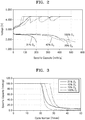
- FIG. 2 is a graph showing charging and discharging performance of the electrochemical battery 100 according to an oxygen concentration in an embodiment in which the electrochemical cell of the battery module 120 is, for example, the metal air cell.
- lithium metal was used as an anode.
- a current density was maintained to about 0.24 milliampere hours per square centimeter (mAh/cm 2 ) during discharge, and discharging was performed until a voltage dropped to about 1.7 V.
- an applied voltage was about 4.3 V during charge.
- a discharge capacity was about 550 milliampere hours per gram (mAh/g).
- the discharge capacity was about 200 mAh/g.
- the discharge capacity when the oxygen concentration is about 70% is greater than the discharge capacity when the oxygen concentration is about 40%.
- the discharge capacity at an oxygen concentration of about 40% was about 80% of the discharge capacity when the oxygen concentration was about 100%, and the discharge capacity when the oxygen concentration was about 70% was not significantly different from the discharge capacity when the oxygen concentration was about 100%.
- FIG. 3 is a graph showing a charge and discharge cycle of the electrochemical battery 100 according to an oxygen concentration in a case where the electrochemical cell of the battery module 120 is, for example, the metal air cell.
- lithium metal was used as an anode.
- a current density was maintained to about 0.24 mAh/cm 2 during discharge, and discharge was performed until a voltage dropped to about 1.7 V.
- an applied voltage was about 4.3 V during charge.
- FIG. 4 is a graph showing a charge and discharge cycle of the electrochemical battery 100 according to an oxygen concentration in in an embodiment in which the electrochemical cell of the battery module 120 is, for example, the metal air cell and showing the results in which charging and discharging were repeated in a state in which a discharge capacity was maintained at about 300 mAh/g.
- a specific capacity reached a selected level of about 80% of an initial specific capacity (e.g., about 240 mAh/g)
- the cycles with the greatest capacity were when oxygen concentrations of about 50% and about 70% were used.
- the oxygen concentration was about 21%
- the discharge capacity of about 300 mAh/g was recorded only once, and the discharge capacity was reduced from a second charge and discharge cycle.
- a specific capacity at oxygen concentrations of about 80% and about 100% reached a level of about 80% of an initial specific capacity from a seventh charge and discharge cycle.
- the discharge efficiency of the electrochemical battery 100 may be temporarily improved, but it may be seen that as charging and discharging are repeated, degradation of the electrochemical battery 100 is rapidly accelerated. While not wanting to be bound by theory, this degradation is understood to occur because an electrode, an electrolyte, and the like are easily oxidized due to excess oxygen. Therefore, when 100% oxygen is supplied to the electrochemical battery 100, a battery life of the electrochemical battery 100 may be shortened. In addition, when the oxygen concentration is about 21%, due to the lack of oxygen, the discharge efficiency and the cycle life of the electrochemical battery 100 were reduced.
- the electrochemical battery 100 may operate at an oxygen concentration that is greater than an oxygen concentration in the atmosphere, i.e., greater than about 21%, and is less than about 100%.
- the controller 150 may adjust the oxygen concentration in the air supplied to the battery module 120 of the electrochemical battery 100 so to maintain an oxygen concentration in a range between a value equal to or greater than about 30% and a value less than about 100%. More specifically, the controller 150 may adjust the oxygen concentration in the air supplied to the battery module 120 so as to maintain in an oxygen concentration in a range between a value equal to or greater than about 35% and a value less than about 95% or in a range between about 50% and about 80%.
- the oxygen concentration in the air supplied to the battery module 120 may be provided in an appropriate range for the fuel cell.
- an oxygen concentration of about 35% to about 95%, about 40% to about 90%, or about 45% to about 85% may be provided.
- the controller 150 may control the operation of the air supplier 110 and the air recirculator 130.
- the controller 150 may control the air supplier 110 and the air recirculator 130 to maintain the oxygen concentration in the battery module 120 to a preset specific value.
- the controller 150 may compare an actual oxygen concentration measured by the oxygen sensor 140 with a target oxygen concentration and control the air supplier 110 and the air recirculator 130 based on a result of the comparison.
- the controller 150 may control the air supplier 110 to adjust an air amount supplied to the battery module 120 and oxygen concentration in the air.
- the controller 150 may control the air recirculator 130 to adjust an amount of air recirculated in the air supplier 110 among the air exhausted through the air outlet port 120b.
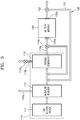
- FIG. 5 is a schematic block diagram of an air supplier 110 and an air recirculator 130 of the electrochemical battery 100 illustrated in FIG. 1 , according to an embodiment.
- the air supplier 110 may include an air suction device 111 configured to suction air from the outside, a moisture remover 112 configured to remove moisture from the suctioned air, and an oxygen generator 113 configured to generate oxygen by separating oxygen from the suctioned air.
- the air suction device 111 may be configured to adjust an air suction amount under control of the controller 150.
- the moisture remover 112 is illustrated in FIG. 5 as being disposed in front of the oxygen generator 113 in an air flow direction, but a placement order may be changed between the oxygen generator 113 and the moisture remover 112.
- the oxygen generator 113 may be disposed in front of the moisture remover 112 in the air flow direction.
- the oxygen generator 113 and the moisture remover 112 may be integrated into a single assembly.
- the embodiment where the moisture remover 112 is disposed in front of the oxygen generator 113 in the air flow direction will be further described for convenience.
- the moisture remover 112 may be configured to remove moisture from outside air suctioned by the air suction device 111.
- an electrochemical cell of a battery module 120 is a metal air cell
- lithium hydroxide may be generated during a discharging of the electrochemical cell. Accordingly, an energy density of the electrochemical battery 100 may be reduced and a battery life thereof may be shortened.
- the moisture remover 112 may be referred to as an air drier.
- the moisture remover 112 may include, for example, an adsorber configured to adsorb moisture in air and a heater configured to heat the adsorber and desorb the moisture adsorbed to the adsorber. The moisture desorbed from the adsorber may be exhausted to the outside through a moisture outlet port 112a.
- the moisture remover 112 may be omitted from the air supplier 110 if desired.
- a humidifier may be used in place of the moisture remover 112 if desired.
- Air dried by the moisture remover 112 may be supplied to the oxygen generator 113.
- the oxygen generator 113 may increase an oxygen concentration in air by removing impurities such as carbon dioxide and nitrogen included in the dried air.
- the oxygen generator 113 may be configured to filter oxygen via an adsorption/desorption method or a membrane method.
- the oxygen which is filtered by the oxygen generator 113 via the adsorption/desorption method or the membrane method, may be supplied to the battery module 120 through a first outlet port 113a.
- the first outlet port 113a of the oxygen generator 113 may be connected to an air inlet port 120a of the battery module 120. A gas remaining after oxygen is separated may be exhausted to the outside through a second outlet port 113b.
- the exhaust gas which is exhausted through the first outlet port 113a or the second outlet port 113b, may be refluxed to the oxygen generator 113 so to facilitate selection of the oxygen concentration to a desired concentration.
- a portion of the air which is supplied to the battery module 120 through the first outlet port 113a, may be refluxed to the oxygen generator 113.
- a first valve 114a may be disposed at a branch point of a reflux path, which is connected to the oxygen generator 113 through the first outlet port 113a.
- the controller 150 may control the first valve 114a to adjust an amount of the air which is refluxed from the first outlet port 113a to the oxygen generator 113.
- a portion of the air, which is exhausted through the second outlet port 113b, may be refluxed to the oxygen generator 113.
- a second valve 114b may be disposed at a branch point of a reflux path, which is connected to the oxygen generator 113 through the second outlet port 113b.
- the controller 150 may control the second valve 114b to adjust an amount of the air which is refluxed from the second outlet port 113b to the oxygen generator 113.
- an air flow passage 131 of the air recirculator 130 may be disposed to supply to the oxygen generator 113 air exhausted through an air outlet port 120b of the battery module 120. Therefore mixed air of the dried outside air supplied through the air suction device 111 and the moisture remover 112 and the air exhausted through the air outlet port 120b of the battery module 120 may be supplied to the oxygen generator 113. Since air is additionally supplied from the air outlet port 120b of the battery module 120, the air suction device 111 may suction an oxygen amount that is less than an oxygen amount consumed by the battery module 120. Accordingly, using this configuration selection of an air amount supplied to the oxygen generator 113 from the air outlet port 120b may be controlled.
- the air recirculator 130 may further include a third valve 132 disposed at the air flow passage 131.
- the controller 150 may control the third valve 132 to adjust the air amount supplied to the oxygen generator 113 from the air outlet port 120b.
- the third valve 132 may be completely opened/closed or partially opened under control of the controller 150.
- the refluxed air may be mixed with the air dried by the moisture remover 112 and the air exhausted from the battery module 120, and the mixed air may be supplied to the oxygen generator 113.
- FIG. 6 is a schematic block diagram of an oxygen generator 113 of the air supplier 110 illustrated in FIG. 5 , according to an embodiment.
- the oxygen generator 113 illustrated in FIG. 6 may be configured to filter oxygen via an adsorption/desorption method.
- the air supplier 110 may adjust the oxygen concentration in the air supplied to the battery module 120 by adjusting an adsorption amount of nitrogen in the air under control of the controller 150.
- the oxygen generator 113 may include a first adsorber 31 and a second adsorber 32, which are disposed in parallel to each other.
- the first adsorber 31 may include a first adsorbent 31a and a first recycler 31 b.
- the second adsorber 32 may include a second adsorbent 32a and a second recycler 32b.
- the first adsorbent 31 a and the second adsorbent 32a may function to adsorb impurities such as nitrogen in air.
- the first adsorbent 31a and the second adsorbent 32a may include at least one selected from zeolite LiX, alumina, a metal-organic framework (MOF), and a zeolite imidazolate framework (ZIF).
- the MOF may include a metal ion or a metal cluster which is coordinated to an organic molecule and may comprise a crystalline compound forming a primary, secondary, or tertiary porous structure.
- the ZIF may comprise a nanoporous compound including a tetrahedral cluster of the formula MN 4 that is linked by an imidazolate ligand (where M is a metal).
- the first recycler 31b and the second recycler 32b may function to recycle the saturated first adsorbent 31a and the saturated second adsorbent 32a, respectively.
- the first recycler 31b and the second recycler 32b may be configured to adjust an inner pressure or temperature of the first adsorber 31 and an inner pressure or temperature of the second adsorber 32, respectively.
- the oxygen generator 113 having the aforementioned structure may operate, for example, in a pressure swing adsorption (PSA) method.
- PSA pressure swing adsorption
- impurities such as nitrogen may be adsorbed to the first adsorbent 31a by increasing the inner pressure of the first adsorber 31.
- the remaining air having an increased oxygen concentration may be exhausted from the first adsorber 31 to the first outlet port 113a.
- the nitrogen adsorbed to the second adsorbent 32a may be desorbed from the second adsorbent 32a by decreasing the inner pressure of the second adsorber 32, and the desorbed nitrogen may be exhausted from the second adsorber 32 to the second outlet port 113b.
- the inner pressure of the first adsorber 31 may be decreased, and the inner pressure of the second adsorber 32 may be increased.
- a desorbing operation may be performed in the first adsorber 31, and an adsorbing operation may be performed in the second adsorber 32.
- the first adsorber 31 and the second adsorber 32 may alternately operate.
- the oxygen concentration in the air supplied to the battery module 120 may be adjusted by adjusting the inner pressure of each of the first adsorber 31 and the second adsorber 32.
- an operation manner of the oxygen generator 113 is not limited to the PSA method, and any suitable method may be used.
- the oxygen generator 113 may be configured to operate in at least one selected from a thermal swing adsorption (TSA) method, a pressure thermal swing adsorption (PTSA) method, and a vacuum swing adsorption (VSA) method.
- TSA thermal swing adsorption
- PTSA pressure thermal swing adsorption
- VSA vacuum swing adsorption
- the PSA method means a technology of primarily adsorbing or capturing a specific gas to the first adsorbent 31a and the second adsorbent 32a at a high partial pressure, and desorbing or exhausting the specific gas when the partial pressure is decreased.
- the TSA method means a technology of primarily adsorbing or capturing a specific gas to the first and second adsorbents 31 a and 32a at room temperature, and desorbing or exhausting the specific gas when the temperature is increased.
- the PTSA method means a technology in which the PSA method and the TSA method are combined.
- the VSA method means a technology of primarily adsorbing or capturing a specific gas to the first and second adsorbents 31a and 32a at about an atmospheric pressure, and desorbing or exhausting the specific gas under a vacuum.
- FIG. 7 is a schematic block diagram of an oxygen generator 113 of the air supplier 110 illustrated in FIG. 5 , according to another embodiment.
- the oxygen generator 113 illustrated in FIG. 7 may be configured to filter oxygen via a membrane method.
- the oxygen generator 113 may include a pump 36 and an oxygen separation module 34 to be configured to separate nitrogen and oxygen in air.
- a membrane 35 may be disposed within the oxygen separation module 34 to selectively separate oxygen.
- One membrane 35 is illustrated in FIG. 7 for convenience, but a plurality of membranes 25, e.g., about 2 to about 100 membranes, may be disposed in a multi-layered structure.
- the membrane 35 may include Ba 0.5 Sr 0.5 Co 0.8 Fe 0.2 O 3- ⁇ (BSCF oxide).
- the air dried by the moisture remover 112 may be supplied to the oxygen separation module 34, and the membrane 35 in the oxygen separation module 34 may filter oxygen in air.
- an air compressor may be further disposed between the moisture remover 112 and the oxygen separation module 34.
- a gas remaining after oxygen is separated in the oxygen separation module 34 may be exhausted to the outside through the second outlet port 113b.
- the pump 36 may supply oxygen to the battery module 120 through the first outlet port 113a by emitting oxygen from the oxygen separation module 34.
- a portion of the air dried by the moisture remover 112 may be mixed with oxygen emitted from the pump 36.
- a valve 37 may be disposed between the moisture remover 112 and the pump 36, and the controller 150 may control the valve 37 to adjust the oxygen concentration in the air supplied to the battery module 120.
- FIG. 8 is a schematic block diagram of an air supplier 110 and an air recirculator 130 of the electrochemical battery 100 illustrated in FIG. 1 , according to another embodiment.
- the air recirculator 130 may further include a membrane 133 configured to separate oxygen from air exhausted through an air outlet port 120b of a battery module 120.
- the membrane 133 may be substantially the same as the membrane 35 illustrated in FIG. 7 .
- the membrane 133 may be disposed within an air flow passage 131. Therefore, the membrane 133 may separate only oxygen from air which is exhausted though the air outlet port 120b of the battery module 120 and is recirculated along the air flow passage 131.
- the oxygen which is separated by the membrane 133, may continuously flow along the air flow passage 131 to be supplied to the battery module 120 through an air inlet port 120a. Air from which the oxygen has been filtered out by the membrane 133, e.g., primarily nitrogen, may be exhausted to the outside through an outlet port 133a.
- Air from which the oxygen has been filtered out by the membrane 133 e.g., primarily nitrogen, may be exhausted to the outside through an outlet port 133a.
- connection of the air flow passage 131 to an oxygen generator 113 can be omitted.
- the air flow passage 131 may be connected between the air inlet port 120a and the air outlet port 120b of the battery module 120.
- a first end portion of the air flow passage 131 may be connected to the air outlet port 120b, and a second end portion thereof may be connected to a first valve 114a or be directly connected to the air inlet port 120a.
- the air flow passage 131 may directly transfer the air exhausted through the air outlet port 120b to the air inlet port 120a.
- the air exhausted through the air outlet port 120b and air supplied through the oxygen generator 113 may be mixed to each other in the air inlet port 120a and be supplied to the battery module 120.
- the air recirculator 130 may further include a pump 134.
- the pump 134 may be disposed on the air flow passage 131 between the air outlet port 120b and the membrane 133 and may allow air to flow from the air outlet port 120b to the air inlet port 120a.
- the performance of the electrochemical battery 100 is improved. Also, a reduction in performance of the electrochemical battery 100, which is caused by a low oxygen concentration, may be prevented, and degradation of a cathode material, which is caused by an excessively high oxygen concentration may be avoided.
- the electrochemical battery 100 may constantly and efficiently maintain the oxygen concentration in the battery module 120 by recirculating the air exhausted from the battery module 120. That is, since oxygen, which does not participate in a reaction within the battery module 120 and is exhausted therefrom is reused, it may be possible to reduce the amount of air supplied to the battery module 120 from the outside. Therefore, it may be possible to reduce an amount of electric power consumed for supplying air to the battery module 120, for example, electric power consumed by the air suction device 111, the moisture remover 112, and the oxygen generator 113.
- FIG. 9 is a diagram illustrating that it is possible for an air amount supplied from the outside to be decreased by using the air recirculator 130 in a structure of the air supplier 110 and the air recirculator 130 illustrated in FIG. 5 in a case where the electrochemical cell of the battery module 120 is, for example, the metal air cell.
- an oxygen amount used for a reaction within the battery module 120 is about 60 liters per minute (L/min)
- the controller 150 maintains an oxygen concentration in air supplied to the battery module 120 at about 70%.
- a proportion of an amount of oxygen actually introduced to the battery module 120 to an oxygen amount used in the battery module 120 is about two.
- the oxygen amount used for the reaction within the battery module 120 is about 60 L/min, about 120 L/min of oxygen may be supplied to the battery module 120. It is assumed that oxygen concentration efficiency of the oxygen generator 113 is about 60%, and it is assumed that all of gases except for oxygen in air are nitrogen.
- the air supplied through the air inlet port 120a of the battery module 120 may include about 120 L/min of oxygen and about 51 L/min of nitrogen. Since the battery module 120 consumes about 60 L/min of oxygen during an operation, air exhausted through the air outlet port 120b may include about 60 L/min of oxygen and about 51 L/min of nitrogen. In this case, an oxygen concentration in the air exhausted through the air outlet port 120b may be about 54%. All of the air exhausted through the air outlet port 120b may be transferred to the oxygen generator 113 through the air flow passage 131. In order to extract about 120 L/min of oxygen, the oxygen generator 113 having oxygen concentration efficiency of about 60% may use about 200 L/min of oxygen.
- the air suction device 111 Since about 60 L/min of oxygen is supplied through the air flow passage 131, the air suction device 111 additionally supplies about 140 L/min of oxygen to the oxygen generator 113.
- the air suction device 111 may suction about 140 L/min of oxygen and about 527 L/min of nitrogen from the outside, the moisture remover 112 may remove moisture from the suctioned air, and then, the moisture-removed air may be supplied to the oxygen generator 113.
- the whole air supplied to the oxygen generator 113 may include about 200 L/min of oxygen and about 578 L/min of nitrogen.
- the oxygen generator 113 may exhaust about 80 L/min of oxygen and about 120 L/min of nitrogen to the outside and supply 120 L/min of oxygen and 51 L/min of nitrogen to the battery module 120 under control of the controller 150.
- the air suction device 111 suctions about 667 L/min of air (about 140 L/min of oxygen and about 527 L/min of nitrogen).
- the air suction device 111 suctions about 952 L/min of air (about 200 L/min of oxygen and about 752 L/min of nitrogen).
- about 752 L/min of nitrogen is calculated by assuming that an oxygen concentration in the atmosphere is 21%.
- an amount of the air suctioned by the air suction device 111 may be reduced by about 30% by recirculating the air exhausted from the battery module 120, and a load of the air suction device 111 and the moisture remover 112 may be reduced by about 30%.
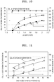
- FIG. 10 is a graph showing a decrease of an air supply flow rate and an oxygen concentration of air exiting the metal air battery according to an air supply ratio of an oxygen amount actually introduced into the battery module 120 to an oxygen amount used in the battery module 120 when an oxygen concentration in air supplied to the battery module 120 is fixed at a constant value in a case where the electrochemical battery cell of the battery module 120 is, for example, the metal air cell.
- the air supply ratio may be about one.
- the oxygen supplied to the battery module 120 may be completely consumed. Accordingly, the oxygen concentration in the air exhausted from the battery module 120 may be about 0%.
- an air supply flow rate may not be decreased in the air suction device 111.
- the air supply ratio of the oxygen amount actually introduced into the battery module 120 to the oxygen amount used in the battery module 120 is increased, the oxygen concentration in the air exhausted from the battery module 120 may be further increased, and the air supply flow rate may be further decreased in the air suction device 111.
- FIG. 11 is a graph showing a decrease of an air supply flow rate, an oxygen concentration of the air supplied to the battery module, and an oxygen concentration of air exiting the battery module according to oxygen concentration efficiency in the oxygen generator 113 when an air supply ratio of an oxygen amount actually introduced into the battery module 120 to an oxygen amount used in the battery module 120 is fixed to a constant value in a case where the electrochemical battery cell of the battery module 120 is, for example, the metal air cell.
- the proportion of the oxygen amount actually introduced to the battery module 120 to the oxygen amount used in the battery module 120 is about two. Referring to FIG.
- the oxygen concentration in the air supplied to the battery module 120 and the oxygen concentration in the air exhausted from the battery module 120 may be increased, and the air supply flow rate may be decreased in the air suction device 111.
- the controller 150 may stop recirculating the air by closing the third valve 132.
- the controller 150 may control the air recirculator 130 to recirculate or not to recirculate the air exhausted from the battery module 120 according to the oxygen concentration in the air exhausted from the battery module 120. Specifically, when the oxygen concentration in the air exhausted from the battery module 120 is less than the oxygen concentration in the atmosphere (i.e., 21 %), the controller 150 may control the air recirculator 130 not to recirculate the air exhausted from the battery module 120.
- FIGS. 9 to 11 in the case the electrochemical cell of the battery module 120 is the metal air cell, the effect of recirculating the air exhausted from the battery module 120 by using the air recirculator 130 has been described. Even when the electrochemical cell of the battery module 120 is the fuel cell, the efficiency of the electrochemical battery 100 may be improved by recirculating, to the air recirculator 130, the air exhausted from the battery module 120.
Landscapes
- Engineering & Computer Science (AREA)
- Manufacturing & Machinery (AREA)
- Chemical & Material Sciences (AREA)
- Chemical Kinetics & Catalysis (AREA)
- Electrochemistry (AREA)
- General Chemical & Material Sciences (AREA)
- Life Sciences & Earth Sciences (AREA)
- Sustainable Development (AREA)
- Sustainable Energy (AREA)
- Hybrid Cells (AREA)
- Fuel Cell (AREA)
Abstract
Description
- The present disclosure relates to an electrochemical battery, and more particularly, to an electrochemical battery which is capable of efficiently and constantly maintaining an oxygen concentration in a battery module by recirculating air exhausted from the battery module.
- Of electrochemical batteries, a metal air battery and a fuel cell have a common feature in that air including oxygen is supplied to a cathode. For example, the metal air battery includes a plurality of metal air cells, and each of the metal air cells includes an anode capable of intercalating and deintercalating ions and a cathode using oxygen in air as an active material. A reduction/oxidation reaction of oxygen introduced from the outside occurs at the cathode, and an oxidation/reduction reaction of a metal occurs at the anode. The metal air battery changes chemical energy generated when the oxidation/reduction reaction occurs into electrical energy and outputs the electrical energy. The metal air battery absorbs oxygen during discharging and emits oxygen during charging.
- In addition, the fuel cell is a device that directly changes chemical energy of a fuel into electrical energy through an electrochemical reaction and is a kind of a power generation device that is capable of continuously generating electricity so long as a fuel is supplied thereto. In the fuel cell, when air including oxygen is supplied to a cathode, and a fuel such as methanol or hydrogen is supplied to an anode, an electrochemical reaction occurs through an electrolyte film between the cathode and the anode, thereby generating electricity.
- To provide improved performance, improved configurations of the electrochemical battery are needed.
- Additional aspects will be set forth in part in the description which follows and, in part, will be apparent from the description, or may be learned by practice of the presented embodiments.
- According to an aspect of an embodiment, an electrochemical battery includes: a battery module including at least one electrochemical cell; an air supplier configured to supply air to the battery module and constantly maintain an oxygen concentration in the air that is supplied to the battery module; and an air recirculator configured to recirculate air exhausted from the battery module, wherein the battery module includes an air inlet port though which air is introduced from the air supplier, and an air outlet port through which air remaining after a reaction in the at least one electrochemical cell is exhausted, and wherein the air recirculator is configured to recirculate the air exhausted through the air outlet port of the battery module to the air inlet port of the battery module.
- The air recirculator may include an air flow passage configured to transfer the air exhausted through the air outlet port to the air supplier.
- The air supplier may include: an air suction device configured to suction air from the outside; and an oxygen generator configured to generate oxygen by separating oxygen from the suctioned air.
- The air flow passage may be connected between the air outlet port of the battery module and the oxygen generator.
- The air supplier may further include a moisture remover configured to remove moisture from the suctioned air, and the air dried by the moisture remover and the air exhausted from the battery module may be mixed with each other and be supplied to the oxygen generator.
- The oxygen generator may be further configured to filter oxygen via an adsorption/desorption method or a membrane method.
- The adsorption/desorption method may include at least one selected from a pressure swing adsorption (PSA) method, a thermal swing adsorption (TSA) method, a pressure thermal swing adsorption (PTSA) method, and a vacuum swing adsorption (VSA) method.
- The oxygen generator may include: a first outlet port connected to the battery module to supply the separated oxygen to the battery module; and a second outlet port configured to exhaust a gas remaining after oxygen is separated.
- The air supplier may be further configured to reflux at least a portion of a gas exhausted through the first outlet port to the oxygen generator.
- The air supplier may further include a moisture remover configured to remove moisture from the suctioned air. The air supplier may be further configured such that the refluxed air is mixed with the air dried by the moisture remover and the air exhausted from the battery module, and the mixed air is supplied to the oxygen generator.
- The air recirculator may include an air flow passage configured to directly transfer the air exhausted through the air outlet port to the air inlet port.
- The air recirculator may further include a membrane disposed on the air flow passage so as to separate oxygen from the air that is exhausted through the air outlet port and is recirculated to the air inlet port.
- The membrane may be configured to supply the separated oxygen to the air inlet port and exhaust gases except for oxygen to the outside.
- The air recirculator may further include an air pump disposed on the air flow passage so as to allow air to flow from the air outlet port to the air inlet port.
- The air recirculator may further include a valve configured to open or close the air flow passage.
- The electrochemical battery may further include a controller configured to control the air supplier and the air recirculator to constantly maintain the oxygen concentration in the air supplied to the battery module.
- The controller may control the air supplier and the air recirculator to constantly maintain the oxygen concentration in the air supplied to the battery module in a range between a value equal to or greater than about 30% and a value less than about 100% based on a total content of the air supplied to the battery module.
- The electrochemical battery may further include an oxygen sensor configured to measure at least one selected from the oxygen concentration in the air supplied to the battery module, an oxygen concentration in the battery module, and the oxygen concentration in the air exhausted from the battery module.
- When the oxygen concentration in the battery module is less than a preset concentration, the controller may control the air supplier to increase the oxygen concentration in the air supplied to the battery module, and when the oxygen concentration in the battery module is greater than the preset concentration, the controller may control the air supplier to decrease the oxygen concentration in the air supplied to the battery module.
- The controller may control the air recirculator to recirculate or not to recirculate the air exhausted from the battery module according to the oxygen concentration in the air exhausted from the battery module.
- When the oxygen concentration in the air exhausted from the battery module is less than an oxygen concentration in the atmosphere, the controller may control the air recirculator not to recirculate the air exhausted from the battery module.
- The air recirculator may include an air flow passage configured to transfer the air exhausted though the air outlet port to the air supplier and a valve configured to open or close the air flow passage.
- The battery module may include at least one metal air cell configured to use oxygen in air as a cathode active material or at least one fuel cell configured to change chemical energy of a fuel into electrical energy through an electrochemical reaction.
- These and/or other aspects will become apparent and more readily appreciated from the following description of the embodiments, taken in conjunction with the accompanying drawings in which:
-
FIG. 1 is a schematic block diagram of an electrochemical battery according to an embodiment; -
FIG. 2 is a graph of voltage (volts, V) versus specific capacity (milliampere hours per gram, mAh/g) showing charging and discharging performance of an electrochemical battery according to an oxygen concentration in a case where the battery module is a metal air cell; -
FIG. 3 is a graph of specific capacity (milliampere hours per gram, mAh/g) versus cycle number showing a charge and discharge cycle of a metal air cell at various oxygen concentrations; -
FIG. 4 is a graph specific capacity (milliampere hours per gram, mAh/g) versus cycle number showing charge and discharge cycles of a metal air battery cell at various oxygen concentrations; -
FIG. 5 is a schematic block diagram of an air supplier and an air recirculator of the electrochemical battery illustrated inFIG. 1 , according to an embodiment; -
FIG. 6 is a schematic block diagram of an oxygen generator of the air supplier illustrated inFIG. 5 , according to an embodiment; -
FIG. 7 is a schematic block diagram of an oxygen generator of the air supplier illustrated inFIG. 5 , according to another embodiment; -
FIG. 8 is a schematic block diagram of an air supplier and an air recirculator of the electrochemical battery illustrated inFIG. 1 , according to another embodiment; -
FIG. 9 is a diagram for illustrating a reduction in an air amount supplied from the outside by using the air recirculator in a structure of the air supplier and the air recirculator illustrated inFIG. 5 in an embodiment in which the battery module is a metal air battery cell; -
FIG. 10 is a graph showing a decrease of an air supply flow-rate (percent, %) and an oxygen concentration of air exiting the metal air battery (percent, %) according to an air supply ratio of an oxygen amount actually introduced into a battery module to an oxygen amount used in the battery module when an oxygen concentration in air supplied to the battery module is fixed to a constant value; and -
FIG. 11 is a graph showing a decrease of an air supply flow rate (percent, %), an oxygen concentration of the air supplied to the battery module, and an oxygen concentration of air exiting the battery module according to oxygen concentration efficiency in an oxygen generator when a proportion of an oxygen amount actually introduced into a battery module to an oxygen amount demanded by the battery module is fixed to a constant value. - Hereinafter, an electrochemical battery maintaining an oxygen concentration by air recirculation will be described in detail with reference to the accompanying drawings, wherein like reference numerals refer to like elements throughout. In the drawings, the dimensions of elements are exaggerated for clarity of the inventive concept. The following embodiments are merely examples, and various modifications may be made thereto. It will be understood that when an element is referred to as being "on," "connected to" or "coupled to" another element, it may be directly on, connected or coupled to the other element, or intervening elements may be present.
- It will be understood that, although the terms "first," "second," "third" etc. may be used herein to describe various elements, components, regions, layers and/or sections, these elements, components, regions, layers and/or sections should not be limited by these terms. These terms are only used to distinguish one element, component, region, layer or section from another element, component, region, layer or section. Thus, "a first element," "component," "region," "layer," or "section" discussed below could be termed a second element, component, region, layer, or section without departing from the teachings herein.
- The terminology used herein is for the purpose of describing particular embodiments only and is not intended to be limiting. As used herein, the singular forms "a," "an," and "the" are intended to include the plural forms, including "at least one," unless the content clearly indicates otherwise. "At least one" is not to be construed as limiting "a" or "an." "Or" means "and/or." As used herein, the term "and/or" includes any and all combinations of one or more of the associated listed items. It will be further understood that the terms "comprises" and/or "comprising," or "includes" and/or "including" when used in this specification, specify the presence of stated features, regions, integers, steps, operations, elements, and/or components, but do not preclude the presence or addition of one or more other features, regions, integers, steps, operations, elements, components, and/or groups thereof.
- Furthermore, relative terms, such as "lower" or "bottom" and "upper" or "top," may be used herein to describe one element's relationship to another element as illustrated in the Figures. It will be understood that relative terms are intended to encompass different orientations of the device in addition to the orientation depicted in the Figures. For example, if the device in one of the figures is turned over, elements described as being on the "lower" side of other elements would then be oriented on "upper" sides of the other elements. The exemplary term "lower," can therefore, encompasses both an orientation of "lower" and "upper," depending on the particular orientation of the figure. Similarly, if the device in one of the figures is turned over, elements described as "below" or "beneath" other elements would then be oriented "above" the other elements. The exemplary terms "below" or "beneath" can, therefore, encompass both an orientation of above and below.
- "About" or "approximately" as used herein is inclusive of the stated value and means within an acceptable range of deviation for the particular value as determined by one of ordinary skill in the art, considering the measurement in question and the error associated with measurement of the particular quantity (i.e., the limitations of the measurement system). For example, "about" can mean within one or more standard deviations, or with in ± 30%, 20%, 10%, or 5% of the stated value.
- Unless otherwise defined, all terms (including technical and scientific terms) used herein have the same meaning as commonly understood by one of ordinary skill in the art to which this disclosure belongs. It will be further understood that terms, such as those defined in commonly used dictionaries, should be interpreted as having a meaning that is consistent with their meaning in the context of the relevant art and the present disclosure, and will not be interpreted in an idealized or overly formal sense unless expressly so defined herein.
- Exemplary embodiments are described herein with reference to cross section illustrations that are schematic illustrations of idealized embodiments. As such, variations from the shapes of the illustrations as a result, for example, of manufacturing techniques and/or tolerances, are to be expected. Thus, embodiments described herein should not be construed as limited to the particular shapes of regions as illustrated herein but are to include deviations in shapes that result, for example, from manufacturing. For example, a region illustrated or described as flat may, typically, have rough and/or nonlinear features. Moreover, sharp angles that are illustrated may be rounded. Thus, the regions illustrated in the figures are schematic in nature and their shapes are not intended to illustrate the precise shape of a region and are not intended to limit the scope of the present claims.
- Gas concentrations are in volume percent. For example, an oxygen concentration of 21 % refers to an oxygen concentration of 21 % by volume.
-
FIG. 1 is a schematic block diagram of anelectrochemical battery 100 according to an embodiment. Referring toFIG. 1 , theelectrochemical battery 100 according to the present embodiment may include abattery module 120 including an electrochemical cell, anair supplier 110 configured to supply air to thebattery module 120, anair recirculator 130 configured to recirculate air exhausted from thebattery module 120, and acontroller 150 configured to control operation of theair supplier 110 and theair recirculator 130. In an embodiment, the controller is configured to maintain a constant oxygen concentration in the air supplied to thebattery module 120. The controller may be configured to operate intermittently or continuously. In addition, theelectrochemical battery 100 may further include anoxygen sensor 140 configured to measure an oxygen concentration. Theoxygen sensor 140 may be disposed to measure at least one selected from an oxygen concentration in air supplied to thebattery module 120, an oxygen concentration in thebattery module 120, and an oxygen concentration in air exhausted from thebattery module 120. - The
battery module 120 may include at least one metal air cell using oxygen in air as a cathode active material or at least one fuel cell which is configured to convert chemical energy of a fuel into electrical energy through an electrochemical reaction. For example, in an embodiment where thebattery module 120 comprises at least one metal air cell, each metal air cell in thebattery module 120 may generate electricity by using an oxidation of a metal and a reduction of oxygen. For example, when a metal of the metal air cell is lithium (Li), the metal air cell may generate electricity through a reaction in which lithium (Li) reacts with oxygen to generate lithium oxide (Li2O2) during discharge. On charge, lithium (Li) may be reduced from lithium oxide and oxygen may be generated. Besides lithium (Li), various other metals such as sodium, zinc, potassium, calcium, magnesium, iron, or aluminum may be used, and a reaction principal thereof may be substantially the same as lithium (Li). For example, thebattery module 120 may include at least one selected from a sodium (Na) air cell, zinc (Zn) air cell, potassium (K) air cell, calcium (Ca) air cell, magnesium (Mg) air cell, iron (Fe) air cell, and an aluminum (Al) air cell, and alloy air cell including at least one of Li, Na, Zn, K, Ca, Mg, and Fe. - In addition, in an embodiment in which the electrochemical battery cell of the
battery module 120 is the fuel cell, each fuel cell in thebattery module 120 may generate electricity by directly changing chemical energy generated through an oxidation of a fuel into electrical energy. For example, when air including oxygen is supplied to a cathode, and a fuel such as methanol or hydrogen is supplied to an anode, an electrochemical reaction occurs through an electrolyte film between the cathode and the anode, thereby generating electricity. - As is further described above, since the
battery module 120 uses oxygen during generation of electricity, it is desirable to continuously supply oxygen to thebattery module 120. The supply of oxygen to thebattery module 120 may be performed by supplying air in the atmosphere to thebattery module 120 or supplying oxygen to thebattery module 120 from an oxygen source such as liquid oxygen. Conventionally, when air from the atmosphere is supplied to thebattery module 120, since an oxygen concentration in the atmosphere is only 21%, in order to sufficiently supply oxygen, air in the atmosphere is usually compressed to a pressure of about 0.5 megaPascals (MPa) and is supplied to thebattery module 120. When the high pressure compressed air is supplied to thebattery module 120, a pressure in thebattery module 120 is increased. For example, when the pressure in thebattery module 120 is greater than about 0.2 MPa, the electrochemical cell may be mechanically abraded and damaged. In addition, since energy is consumed for compressing air, the total efficiency of theelectrochemical battery 100 may be reduced. - The
air supplier 110 according to the present embodiment may be configured to control the oxygen concentration in the air supplied to thebattery module 120 and may avoid the supplying of compressed air to thebattery module 120. For example, after air in the atmosphere is suctioned, theair supplier 110 may increase the oxygen concentration in the air supplied to thebattery module 120 by removing moisture and nitrogen from the air. In particular, theair supplier 110 may be configured to improve the performance of theelectrochemical battery 100 by adjusting the oxygen concentration in the air supplied to thebattery module 120. - The air recirculator 130 may be configured to recirculate air by supplying, to the
air supplier 110, at least a portion of air exhausted from thebattery module 120. For example, thebattery module 120 may include anair inlet port 120a through which air is introduced from theair supplier 110 and anair outlet port 120b through which air remaining after a reaction in the electrochemical battery cell is exhausted. The air recirculator 130 may include anair flow passage 131 configured for transferring the air exhausted through theair outlet port 120b to theair supplier 110. In order to cause a sufficient reaction or a reaction under a uniform current density in the electrochemical cell, theair supplier 110 may supply, to thebattery module 120, an oxygen amount that is greater than an oxygen amount used by the electrochemical cell. Therefore, unreacted residual oxygen may be included in the air exhausted through theair outlet port 120b. The air recirculator 130 may reduce a load of theair supplier 110 by recirculating, to thebattery module 120, the air exhausted through theair outlet port 120b of thebattery module 120. - The
controller 150 may adjust the oxygen concentration in the air supplied to thebattery module 120 by controlling an operation of theair supplier 110 and theair recirculator 130. For example, a feedforward control method that does not consider the state of thebattery module 120 may be used. The oxygen concentration in the air supplied by theair supplier 110 may be fixed to a specific value, and thecontroller 150 may control theair supplier 110 such that theair supplier 110 supplies air having a specific oxygen concentration regardless of an actual oxygen concentration in thebattery module 120. - In addition, the
controller 150 may control the operation of theair supplier 110 and theair recirculator 130 in a feedback method, based on the oxygen concentration in the air supplied to thebattery module 120, the oxygen concentration in thebattery module 120, and the oxygen concentration in the air exhausted from thebattery module 120. For example, thecontroller 150 may receive a measurement result from theoxygen sensor 140. When the oxygen concentration in thebattery module 120 is less than a preset concentration, thecontroller 150 may control theair supplier 110 to increase the oxygen concentration in the air supplied to thebattery module 120. In addition, when the oxygen concentration in thebattery module 120 is greater than the preset concentration, thecontroller 150 may control theair supplier 110 to decrease the oxygen concentration in the air supplied to thebattery module 120. - Hereinafter, an oxygen concentration for improving operation of the
electrochemical battery 100 will be further disclosed. For example,FIGS. 2 to 4 are graphs showing a change in performance of theelectrochemical battery 100 according to the oxygen concentration in the air supplied to thebattery module 120 in an embodiment in which the electrochemical cell of thebattery module 120 is the metal air cell. -
FIG. 2 is a graph showing charging and discharging performance of theelectrochemical battery 100 according to an oxygen concentration in an embodiment in which the electrochemical cell of thebattery module 120 is, for example, the metal air cell. In the graph ofFIG. 2 , lithium metal was used as an anode. A current density was maintained to about 0.24 milliampere hours per square centimeter (mAh/cm2) during discharge, and discharging was performed until a voltage dropped to about 1.7 V. In addition, an applied voltage was about 4.3 V during charge. Referring to the graph ofFIG. 2 , until the voltage dropped to about 1.7 V, when the oxygen concentration was about 100%, a discharge capacity was about 550 milliampere hours per gram (mAh/g). When the oxygen concentration was about 21%, the discharge capacity was about 200 mAh/g. The discharge capacity when the oxygen concentration is about 70% is greater than the discharge capacity when the oxygen concentration is about 40%. The discharge capacity at an oxygen concentration of about 40% was about 80% of the discharge capacity when the oxygen concentration was about 100%, and the discharge capacity when the oxygen concentration was about 70% was not significantly different from the discharge capacity when the oxygen concentration was about 100%. -
FIG. 3 is a graph showing a charge and discharge cycle of theelectrochemical battery 100 according to an oxygen concentration in a case where the electrochemical cell of thebattery module 120 is, for example, the metal air cell. In the graph ofFIG. 3 , lithium metal was used as an anode. A current density was maintained to about 0.24 mAh/cm2 during discharge, and discharge was performed until a voltage dropped to about 1.7 V. In addition, an applied voltage was about 4.3 V during charge. It was shown that after charging and discharging were repeated in a state in which a discharge capacity was maintained to about 100 mAh/g, a charge and discharge cycle at an oxygen concentration of about 21% was similar to a charge and discharge cycle at an oxygen concentration of about 100%, and after charging and discharging were performed about 20 times, performance degradation occurred at the oxygen concentrations of about 21% and about 100%. The charge and discharge cycle provided the greatest capacity when the oxygen concentration was about 70%. -
FIG. 4 is a graph showing a charge and discharge cycle of theelectrochemical battery 100 according to an oxygen concentration in in an embodiment in which the electrochemical cell of thebattery module 120 is, for example, the metal air cell and showing the results in which charging and discharging were repeated in a state in which a discharge capacity was maintained at about 300 mAh/g. Until a specific capacity reached a selected level of about 80% of an initial specific capacity (e.g., about 240 mAh/g), the cycles with the greatest capacity were when oxygen concentrations of about 50% and about 70% were used. When the oxygen concentration was about 21%, the discharge capacity of about 300 mAh/g was recorded only once, and the discharge capacity was reduced from a second charge and discharge cycle. A specific capacity at oxygen concentrations of about 80% and about 100% reached a level of about 80% of an initial specific capacity from a seventh charge and discharge cycle. - From the above-described results, when the oxygen concentration is about 100%, the discharge efficiency of the
electrochemical battery 100 may be temporarily improved, but it may be seen that as charging and discharging are repeated, degradation of theelectrochemical battery 100 is rapidly accelerated. While not wanting to be bound by theory, this degradation is understood to occur because an electrode, an electrolyte, and the like are easily oxidized due to excess oxygen. Therefore, when 100% oxygen is supplied to theelectrochemical battery 100, a battery life of theelectrochemical battery 100 may be shortened. In addition, when the oxygen concentration is about 21%, due to the lack of oxygen, the discharge efficiency and the cycle life of theelectrochemical battery 100 were reduced. - As can be seen from the above, in order to improve the performance and the battery life of the
electrochemical battery 100, theelectrochemical battery 100 may operate at an oxygen concentration that is greater than an oxygen concentration in the atmosphere, i.e., greater than about 21%, and is less than about 100%. For example, thecontroller 150 may adjust the oxygen concentration in the air supplied to thebattery module 120 of theelectrochemical battery 100 so to maintain an oxygen concentration in a range between a value equal to or greater than about 30% and a value less than about 100%. More specifically, thecontroller 150 may adjust the oxygen concentration in the air supplied to thebattery module 120 so as to maintain in an oxygen concentration in a range between a value equal to or greater than about 35% and a value less than about 95% or in a range between about 50% and about 80%. - In
FIGS. 2 to 4 , while the embodiment where the electrochemical cell of thebattery module 120 is the metal air cell, even when the electrochemical cell of thebattery module 120 is a fuel cell, the oxygen concentration in the air supplied to thebattery module 120 may be provided in an appropriate range for the fuel cell. For example, when thebattery module 120 includes a fuel cell, an oxygen concentration of about 35% to about 95%, about 40% to about 90%, or about 45% to about 85% may be provided. - In order to maintain the oxygen concentration in the air supplied to the
battery module 120 as described above, thecontroller 150 may control the operation of theair supplier 110 and theair recirculator 130. For example, thecontroller 150 may control theair supplier 110 and theair recirculator 130 to maintain the oxygen concentration in thebattery module 120 to a preset specific value. At this time, thecontroller 150 may compare an actual oxygen concentration measured by theoxygen sensor 140 with a target oxygen concentration and control theair supplier 110 and theair recirculator 130 based on a result of the comparison. For example, thecontroller 150 may control theair supplier 110 to adjust an air amount supplied to thebattery module 120 and oxygen concentration in the air. Thecontroller 150 may control theair recirculator 130 to adjust an amount of air recirculated in theair supplier 110 among the air exhausted through theair outlet port 120b. -
FIG. 5 is a schematic block diagram of anair supplier 110 and anair recirculator 130 of theelectrochemical battery 100 illustrated inFIG. 1 , according to an embodiment. Referring toFIG. 5 , theair supplier 110 may include anair suction device 111 configured to suction air from the outside, amoisture remover 112 configured to remove moisture from the suctioned air, and anoxygen generator 113 configured to generate oxygen by separating oxygen from the suctioned air. Theair suction device 111 may be configured to adjust an air suction amount under control of thecontroller 150. Themoisture remover 112 is illustrated inFIG. 5 as being disposed in front of theoxygen generator 113 in an air flow direction, but a placement order may be changed between theoxygen generator 113 and themoisture remover 112. For example, theoxygen generator 113 may be disposed in front of themoisture remover 112 in the air flow direction. In addition, theoxygen generator 113 and themoisture remover 112 may be integrated into a single assembly. Hereinafter, the embodiment where themoisture remover 112 is disposed in front of theoxygen generator 113 in the air flow direction will be further described for convenience. - The
moisture remover 112 may be configured to remove moisture from outside air suctioned by theair suction device 111. In a case where an electrochemical cell of abattery module 120 is a metal air cell, when moisture is present in the air, lithium hydroxide may be generated during a discharging of the electrochemical cell. Accordingly, an energy density of theelectrochemical battery 100 may be reduced and a battery life thereof may be shortened. In this regard, themoisture remover 112 may be referred to as an air drier. Although not illustrated in detail, themoisture remover 112 may include, for example, an adsorber configured to adsorb moisture in air and a heater configured to heat the adsorber and desorb the moisture adsorbed to the adsorber. The moisture desorbed from the adsorber may be exhausted to the outside through amoisture outlet port 112a. - However, in an embodiment in which the electrochemical cell of the
battery module 120 is a fuel cell, themoisture remover 112 may be omitted from theair supplier 110 if desired. Alternatively, a humidifier may be used in place of themoisture remover 112 if desired. - Air dried by the
moisture remover 112 may be supplied to theoxygen generator 113. Theoxygen generator 113 may increase an oxygen concentration in air by removing impurities such as carbon dioxide and nitrogen included in the dried air. For example, theoxygen generator 113 may be configured to filter oxygen via an adsorption/desorption method or a membrane method. The oxygen, which is filtered by theoxygen generator 113 via the adsorption/desorption method or the membrane method, may be supplied to thebattery module 120 through afirst outlet port 113a. To this end, thefirst outlet port 113a of theoxygen generator 113 may be connected to anair inlet port 120a of thebattery module 120. A gas remaining after oxygen is separated may be exhausted to the outside through asecond outlet port 113b. - As illustrated in
FIG. 5 , the exhaust gas, which is exhausted through thefirst outlet port 113a or thesecond outlet port 113b, may be refluxed to theoxygen generator 113 so to facilitate selection of the oxygen concentration to a desired concentration. For example, a portion of the air, which is supplied to thebattery module 120 through thefirst outlet port 113a, may be refluxed to theoxygen generator 113. To this end, afirst valve 114a may be disposed at a branch point of a reflux path, which is connected to theoxygen generator 113 through thefirst outlet port 113a. Thecontroller 150 may control thefirst valve 114a to adjust an amount of the air which is refluxed from thefirst outlet port 113a to theoxygen generator 113. In the same manner, a portion of the air, which is exhausted through thesecond outlet port 113b, may be refluxed to theoxygen generator 113. To this end, asecond valve 114b may be disposed at a branch point of a reflux path, which is connected to theoxygen generator 113 through thesecond outlet port 113b. Thecontroller 150 may control thesecond valve 114b to adjust an amount of the air which is refluxed from thesecond outlet port 113b to theoxygen generator 113. - In addition, an
air flow passage 131 of theair recirculator 130 may be disposed to supply to theoxygen generator 113 air exhausted through anair outlet port 120b of thebattery module 120. Therefore mixed air of the dried outside air supplied through theair suction device 111 and themoisture remover 112 and the air exhausted through theair outlet port 120b of thebattery module 120 may be supplied to theoxygen generator 113. Since air is additionally supplied from theair outlet port 120b of thebattery module 120, theair suction device 111 may suction an oxygen amount that is less than an oxygen amount consumed by thebattery module 120. Accordingly, using this configuration selection of an air amount supplied to theoxygen generator 113 from theair outlet port 120b may be controlled. To this end, theair recirculator 130 may further include athird valve 132 disposed at theair flow passage 131. Thecontroller 150 may control thethird valve 132 to adjust the air amount supplied to theoxygen generator 113 from theair outlet port 120b. Thethird valve 132 may be completely opened/closed or partially opened under control of thecontroller 150. In addition, when a portion of the air supplied to thebattery module 120 from thefirst outlet port 113a is refluxed to theoxygen generator 113, the refluxed air may be mixed with the air dried by themoisture remover 112 and the air exhausted from thebattery module 120, and the mixed air may be supplied to theoxygen generator 113. -
FIG. 6 is a schematic block diagram of anoxygen generator 113 of theair supplier 110 illustrated inFIG. 5 , according to an embodiment. Theoxygen generator 113 illustrated inFIG. 6 may be configured to filter oxygen via an adsorption/desorption method. In this case, theair supplier 110 may adjust the oxygen concentration in the air supplied to thebattery module 120 by adjusting an adsorption amount of nitrogen in the air under control of thecontroller 150. For example, referring toFIG. 6 , theoxygen generator 113 may include afirst adsorber 31 and asecond adsorber 32, which are disposed in parallel to each other. Thefirst adsorber 31 may include afirst adsorbent 31a and afirst recycler 31 b. Thesecond adsorber 32 may include asecond adsorbent 32a and asecond recycler 32b. - The
first adsorbent 31 a and thesecond adsorbent 32a may function to adsorb impurities such as nitrogen in air. For example, thefirst adsorbent 31a and thesecond adsorbent 32a may include at least one selected from zeolite LiX, alumina, a metal-organic framework (MOF), and a zeolite imidazolate framework (ZIF). The MOF may include a metal ion or a metal cluster which is coordinated to an organic molecule and may comprise a crystalline compound forming a primary, secondary, or tertiary porous structure. In addition, the ZIF may comprise a nanoporous compound including a tetrahedral cluster of the formula MN4 that is linked by an imidazolate ligand (where M is a metal). - The
first recycler 31b and thesecond recycler 32b may function to recycle the saturatedfirst adsorbent 31a and the saturatedsecond adsorbent 32a, respectively. In order to recycle the saturatedfirst adsorbent 31a and the saturatedsecond adsorbent 32a, thefirst recycler 31b and thesecond recycler 32b may be configured to adjust an inner pressure or temperature of thefirst adsorber 31 and an inner pressure or temperature of thesecond adsorber 32, respectively. - The
oxygen generator 113 having the aforementioned structure may operate, for example, in a pressure swing adsorption (PSA) method. For example, impurities such as nitrogen may be adsorbed to thefirst adsorbent 31a by increasing the inner pressure of thefirst adsorber 31. The remaining air having an increased oxygen concentration may be exhausted from thefirst adsorber 31 to thefirst outlet port 113a. Also, the nitrogen adsorbed to thesecond adsorbent 32a may be desorbed from thesecond adsorbent 32a by decreasing the inner pressure of thesecond adsorber 32, and the desorbed nitrogen may be exhausted from thesecond adsorber 32 to thesecond outlet port 113b. When thefirst adsorbent 31 a is saturated, the inner pressure of thefirst adsorber 31 may be decreased, and the inner pressure of thesecond adsorber 32 may be increased. In this case, a desorbing operation may be performed in thefirst adsorber 31, and an adsorbing operation may be performed in thesecond adsorber 32. In such a manner, thefirst adsorber 31 and thesecond adsorber 32 may alternately operate. At this time, the oxygen concentration in the air supplied to thebattery module 120 may be adjusted by adjusting the inner pressure of each of thefirst adsorber 31 and thesecond adsorber 32. - However, an operation manner of the
oxygen generator 113 is not limited to the PSA method, and any suitable method may be used. For example, in addition to the PSA method, theoxygen generator 113 may be configured to operate in at least one selected from a thermal swing adsorption (TSA) method, a pressure thermal swing adsorption (PTSA) method, and a vacuum swing adsorption (VSA) method. The PSA method means a technology of primarily adsorbing or capturing a specific gas to thefirst adsorbent 31a and thesecond adsorbent 32a at a high partial pressure, and desorbing or exhausting the specific gas when the partial pressure is decreased. In addition, the TSA method means a technology of primarily adsorbing or capturing a specific gas to the first andsecond adsorbents second adsorbents -
FIG. 7 is a schematic block diagram of anoxygen generator 113 of theair supplier 110 illustrated inFIG. 5 , according to another embodiment. Theoxygen generator 113 illustrated inFIG. 7 may be configured to filter oxygen via a membrane method. Referring toFIG. 7 , theoxygen generator 113 may include apump 36 and anoxygen separation module 34 to be configured to separate nitrogen and oxygen in air. Amembrane 35 may be disposed within theoxygen separation module 34 to selectively separate oxygen. Onemembrane 35 is illustrated inFIG. 7 for convenience, but a plurality ofmembranes 25, e.g., about 2 to about 100 membranes, may be disposed in a multi-layered structure. For example, themembrane 35 may include Ba0.5Sr0.5Co0.8Fe0.2O3-δ (BSCF oxide). - The air dried by the
moisture remover 112 may be supplied to theoxygen separation module 34, and themembrane 35 in theoxygen separation module 34 may filter oxygen in air. According to demand, in order to improve separation efficiency by sufficiently supplying air to theoxygen separation module 34, an air compressor may be further disposed between themoisture remover 112 and theoxygen separation module 34. A gas remaining after oxygen is separated in theoxygen separation module 34 may be exhausted to the outside through thesecond outlet port 113b. Thepump 36 may supply oxygen to thebattery module 120 through thefirst outlet port 113a by emitting oxygen from theoxygen separation module 34. At this time, in order to adjust the oxygen concentration in the air supplied to thebattery module 120, a portion of the air dried by themoisture remover 112 may be mixed with oxygen emitted from thepump 36. For example, avalve 37 may be disposed between themoisture remover 112 and thepump 36, and thecontroller 150 may control thevalve 37 to adjust the oxygen concentration in the air supplied to thebattery module 120. -
FIG. 8 is a schematic block diagram of anair supplier 110 and anair recirculator 130 of theelectrochemical battery 100 illustrated inFIG. 1 , according to another embodiment. Referring toFIG. 8 , theair recirculator 130 may further include amembrane 133 configured to separate oxygen from air exhausted through anair outlet port 120b of abattery module 120. Themembrane 133 may be substantially the same as themembrane 35 illustrated inFIG. 7 . For example, themembrane 133 may be disposed within anair flow passage 131. Therefore, themembrane 133 may separate only oxygen from air which is exhausted though theair outlet port 120b of thebattery module 120 and is recirculated along theair flow passage 131. The oxygen, which is separated by themembrane 133, may continuously flow along theair flow passage 131 to be supplied to thebattery module 120 through anair inlet port 120a. Air from which the oxygen has been filtered out by themembrane 133, e.g., primarily nitrogen, may be exhausted to the outside through anoutlet port 133a. - In the case of the present embodiment, since the oxygen in the air exhausted through the
air outlet port 120b is separated by themembrane 133 within theair flow passage 131, connection of theair flow passage 131 to anoxygen generator 113 can be omitted. As illustrated inFIG. 8 , theair flow passage 131 may be connected between theair inlet port 120a and theair outlet port 120b of thebattery module 120. For example, a first end portion of theair flow passage 131 may be connected to theair outlet port 120b, and a second end portion thereof may be connected to afirst valve 114a or be directly connected to theair inlet port 120a. In this case, theair flow passage 131 may directly transfer the air exhausted through theair outlet port 120b to theair inlet port 120a. The air exhausted through theair outlet port 120b and air supplied through theoxygen generator 113 may be mixed to each other in theair inlet port 120a and be supplied to thebattery module 120. - In addition, in order to improve oxygen separation efficiency of the
membrane 133 and allow air to smoothly flow in theair flow passage 131, theair recirculator 130 may further include apump 134. For example, thepump 134 may be disposed on theair flow passage 131 between theair outlet port 120b and themembrane 133 and may allow air to flow from theair outlet port 120b to theair inlet port 120a. - Since the above-described
electrochemical battery 100 maintains the oxygen concentration in the air supplied to thebattery module 120 to a range greater than a range of an oxygen concentration in the atmosphere, the performance of theelectrochemical battery 100 is improved. Also, a reduction in performance of theelectrochemical battery 100, which is caused by a low oxygen concentration, may be prevented, and degradation of a cathode material, which is caused by an excessively high oxygen concentration may be avoided. In addition, according to embodiments, theelectrochemical battery 100 may constantly and efficiently maintain the oxygen concentration in thebattery module 120 by recirculating the air exhausted from thebattery module 120. That is, since oxygen, which does not participate in a reaction within thebattery module 120 and is exhausted therefrom is reused, it may be possible to reduce the amount of air supplied to thebattery module 120 from the outside. Therefore, it may be possible to reduce an amount of electric power consumed for supplying air to thebattery module 120, for example, electric power consumed by theair suction device 111, themoisture remover 112, and theoxygen generator 113. -
FIG. 9 is a diagram illustrating that it is possible for an air amount supplied from the outside to be decreased by using theair recirculator 130 in a structure of theair supplier 110 and theair recirculator 130 illustrated inFIG. 5 in a case where the electrochemical cell of thebattery module 120 is, for example, the metal air cell. In an example ofFIG. 9 , it is assumed that an oxygen amount used for a reaction within thebattery module 120 is about 60 liters per minute (L/min), and it is assumed that thecontroller 150 maintains an oxygen concentration in air supplied to thebattery module 120 at about 70%. In addition, it is assumed that a proportion of an amount of oxygen actually introduced to thebattery module 120 to an oxygen amount used in thebattery module 120 is about two. That is, when the oxygen amount used for the reaction within thebattery module 120 is about 60 L/min, about 120 L/min of oxygen may be supplied to thebattery module 120. It is assumed that oxygen concentration efficiency of theoxygen generator 113 is about 60%, and it is assumed that all of gases except for oxygen in air are nitrogen. - Referring to
FIG. 9 , the air supplied through theair inlet port 120a of thebattery module 120 may include about 120 L/min of oxygen and about 51 L/min of nitrogen. Since thebattery module 120 consumes about 60 L/min of oxygen during an operation, air exhausted through theair outlet port 120b may include about 60 L/min of oxygen and about 51 L/min of nitrogen. In this case, an oxygen concentration in the air exhausted through theair outlet port 120b may be about 54%. All of the air exhausted through theair outlet port 120b may be transferred to theoxygen generator 113 through theair flow passage 131. In order to extract about 120 L/min of oxygen, theoxygen generator 113 having oxygen concentration efficiency of about 60% may use about 200 L/min of oxygen. Since about 60 L/min of oxygen is supplied through theair flow passage 131, theair suction device 111 additionally supplies about 140 L/min of oxygen to theoxygen generator 113. For example, since an oxygen concentration in the atmosphere is 21%, theair suction device 111 may suction about 140 L/min of oxygen and about 527 L/min of nitrogen from the outside, themoisture remover 112 may remove moisture from the suctioned air, and then, the moisture-removed air may be supplied to theoxygen generator 113. Accordingly, the whole air supplied to theoxygen generator 113 may include about 200 L/min of oxygen and about 578 L/min of nitrogen. After that, in order to maintain the oxygen concentration in the air supplied to thebattery module 120 to about 70%, theoxygen generator 113 may exhaust about 80 L/min of oxygen and about 120 L/min of nitrogen to the outside and supply 120 L/min of oxygen and 51 L/min of nitrogen to thebattery module 120 under control of thecontroller 150. - As can be seen from an example of
FIG. 9 , when the air exhausted from thebattery module 120 is recirculated by using theair recirculator 130, theair suction device 111 suctions about 667 L/min of air (about 140 L/min of oxygen and about 527 L/min of nitrogen). On the contrary, when the air exhausted from thebattery module 120 is not recirculated, in order to supply about 200 L/min of oxygen to theoxygen generator 113, theair suction device 111 suctions about 952 L/min of air (about 200 L/min of oxygen and about 752 L/min of nitrogen). About 752 L/min of nitrogen is calculated by assuming that an oxygen concentration in the atmosphere is 21%. Therefore, an amount of the air suctioned by theair suction device 111 may be reduced by about 30% by recirculating the air exhausted from thebattery module 120, and a load of theair suction device 111 and themoisture remover 112 may be reduced by about 30%. -
FIG. 10 is a graph showing a decrease of an air supply flow rate and an oxygen concentration of air exiting the metal air battery according to an air supply ratio of an oxygen amount actually introduced into thebattery module 120 to an oxygen amount used in thebattery module 120 when an oxygen concentration in air supplied to thebattery module 120 is fixed at a constant value in a case where the electrochemical battery cell of thebattery module 120 is, for example, the metal air cell. For example, in a case where the oxygen amount used in thebattery module 120 is about 60 L/min, when about 60 L/min of oxygen is supplied, the air supply ratio may be about one. When the air supply ratio is about one, the oxygen supplied to thebattery module 120 may be completely consumed. Accordingly, the oxygen concentration in the air exhausted from thebattery module 120 may be about 0%. Therefore, an air supply flow rate may not be decreased in theair suction device 111. Referring to the graph ofFIG. 10 , as the air supply ratio of the oxygen amount actually introduced into thebattery module 120 to the oxygen amount used in thebattery module 120 is increased, the oxygen concentration in the air exhausted from thebattery module 120 may be further increased, and the air supply flow rate may be further decreased in theair suction device 111. -
FIG. 11 is a graph showing a decrease of an air supply flow rate, an oxygen concentration of the air supplied to the battery module, and an oxygen concentration of air exiting the battery module according to oxygen concentration efficiency in theoxygen generator 113 when an air supply ratio of an oxygen amount actually introduced into thebattery module 120 to an oxygen amount used in thebattery module 120 is fixed to a constant value in a case where the electrochemical battery cell of thebattery module 120 is, for example, the metal air cell. In the graph ofFIG. 11 , it is assumed that the proportion of the oxygen amount actually introduced to thebattery module 120 to the oxygen amount used in thebattery module 120 is about two. Referring toFIG. 11 , as the oxygen concentration efficiency of theoxygen generator 113 is increased, the oxygen concentration in the air supplied to thebattery module 120 and the oxygen concentration in the air exhausted from thebattery module 120 may be increased, and the air supply flow rate may be decreased in theair suction device 111. - As can be seen from the graphs of
FIGS. 10 and 11 , when taking into consideration the total efficiency of theelectrochemical battery 100, in an embodiment wherein the decrease effect of the air supply flow rate is not great in theair suction device 111, it may be possible to stop recirculating air. That is, in an embodiment wherein the ratio of the oxygen amount actually introduced into thebattery module 120 to the oxygen amount used in thebattery module 120 is low, in an embodiment wherein the oxygen concentration efficiency of theoxygen generator 113 is low, or in a case where the oxygen concentration in the air exhausted from thebattery module 120 is low, thecontroller 150 may stop recirculating the air by closing thethird valve 132. For example, thecontroller 150 may control theair recirculator 130 to recirculate or not to recirculate the air exhausted from thebattery module 120 according to the oxygen concentration in the air exhausted from thebattery module 120. Specifically, when the oxygen concentration in the air exhausted from thebattery module 120 is less than the oxygen concentration in the atmosphere (i.e., 21 %), thecontroller 150 may control theair recirculator 130 not to recirculate the air exhausted from thebattery module 120. - In
FIGS. 9 to 11 , in the case the electrochemical cell of thebattery module 120 is the metal air cell, the effect of recirculating the air exhausted from thebattery module 120 by using theair recirculator 130 has been described. Even when the electrochemical cell of thebattery module 120 is the fuel cell, the efficiency of theelectrochemical battery 100 may be improved by recirculating, to theair recirculator 130, the air exhausted from thebattery module 120. - For understanding, embodiments of the electrochemical battery maintaining the oxygen concentration by air recirculation have been described and illustrated in the accompanying drawings. However, it will be understood that the embodiments are examples and shall not limit the scope of this disclosure. It will be understood that the scope of this disclosure is not limited to the illustrations and description provided herein and that various modifications may be made those of ordinary skill in the art.
- It should be understood that embodiments described herein should be considered in a descriptive sense only and not for purposes of limitation. Descriptions of features or aspects within each embodiment should be considered as available for other similar features or aspects in other embodiments.
- While one or more embodiments have been described with reference to the figures, it will be understood by those of ordinary skill in the art that various changes in form and details may be made therein without departing from the scope as defined by the following claims.
Claims (15)
- An electrochemical battery comprising:a battery module comprising at least one electrochemical cell;an air supplier configured to supply air to the battery module and maintain an oxygen concentration in the air that is supplied to the battery module; andan air recirculator configured to recirculate air exhausted from the battery module,wherein the battery module comprisesan air inlet port though which air is introduced from the air supplier, andan air outlet port through which air remaining after a reaction in the at least one electrochemical cell is exhausted, andwherein the air recirculator is configured to recirculate the air exhausted through the air outlet port of the battery module to the air inlet port of the battery module.
- The electrochemical battery of claim 1, wherein
the battery module comprises at least one metal air cell configured to use oxygen in air as a cathode active material, or
at least one fuel cell configured to change chemical energy of a fuel into electrical energy through an electrochemical reaction. - The electrochemical battery of claim 1 or 2, wherein
the air recirculator comprises an air flow passage configured to transfer the air exhausted through the air outlet port to the air supplier. - The electrochemical battery of claim 3, wherein the air supplier comprises:an air suction device configured to suction air from the outside; andan oxygen generator configured to generate oxygen by separating oxygen from the suctioned air.
- The electrochemical battery of claim 4, wherein
the oxygen generator is further configured to filter oxygen via an adsorption/desorption method or a membrane method;
and optionally wherein the adsorbtion/desorbtion method comprises at least one selected from a pressure swing adsorption method, a thermal swing adsorption method, a pressure thermal swing adsorption method, and a vacuum swing adsorption method. - The electrochemical battery of claim 4 or 5, wherein
the air flow passage connects the air outlet port of the battery module and the oxygen generator; and/or
the air supplier further comprises a moisture remover configured to remove moisture from the suctioned air, wherein the air supplier is configured to mix the air dried by the moisture remover and the air exhausted from the battery module, and wherein the air supplier is configured to supply the mixed air dried by the moisture remover and the air exhausted from the battery module to the oxygen generator. - The electrochemical battery of claim 4 or 5, wherein
the oxygen generator comprises:a first outlet port connected to the battery module and configured to supply the separated oxygen to the battery module; anda second outlet port configured to exhaust an exhaust gas remaining after oxygen is separated from the suctioned air. - The electrochemical battery of claim 7, wherein
the air supplier is further configured to reflux at least a portion of a gas exhausted through the first outlet port to the oxygen generator;
and optionally wherein the air supplier further comprises a moisture remover configured to remove moisture from the suctioned air, wherein the air supplier is further configured to mix the refluxed air with the air dried by the moisture remover and the air exhausted from the battery module, and wherein the air supplier is configured to supply the mixed air to the oxygen generator. - The electrochemical battery of claim 1 or 2, wherein
the air recirculator comprises an air flow passage configured to directly transfer the air exhausted through the air outlet port to the air inlet port. - The electrochemical battery of claim 9,
wherein the air recirculator further comprises a membrane disposed on the air flow passage, and
wherein the membrane is configured to separate oxygen from the air that is exhausted through the air outlet port and is recirculated to the air inlet port. - The electrochemical battery of claim 10,
wherein the membrane is configured to supply the separated oxygen to the air inlet port and is configured to exhaust gases except for oxygen to an outside; and/or
wherein the air recirculator further comprises an air pump disposed on the air flow passage, and
wherein the air pump is configured to allow air to flow from the air outlet port to the air inlet port; and/or
the air recirculator further comprises a valve configured to open or close the air flow passage. - The electrochemical battery of any preceding claim, further comprising a controller configured to control the air supplier and the air recirculator, and wherein the air controller is configured to maintain the oxygen concentration in the air supplied to the battery module,
and optionally wherein the controller controls the air supplier and the air recirculator, and wherein the controller is configured to maintain the oxygen concentration in the air supplied to the battery module in a range between a value equal to or greater than 30% and a value less than 100%, based on a total content of the air supplied to the battery module. - The electrochemical battery of claim 12, further comprising an oxygen sensor configured to measure at least one selected from the oxygen concentration in the air supplied to the battery module, an oxygen concentration in the battery module, and the oxygen concentration in the air exhausted from the battery module,
and optionally wherein when the oxygen concentration in the battery module is less than a preset concentration, the controller controls the air supplier to increase the oxygen concentration in the air supplied to the battery module; and when the oxygen concentration in the battery module is greater than the preset concentration, the controller controls the air supplier to decrease the oxygen concentration in the air supplied to the battery module. - The electrochemical battery of claim 13, wherein
the controller controls the air recirculator to recirculate or not to recirculate the air exhausted from the battery module according to the oxygen concentration in the air exhausted from the battery module;
and optionally wherein when the oxygen concentration in the air exhausted from the battery module is less than an oxygen concentration of atmospheric air, the controller controls the air recirculator to not recirculate the air exhausted from the battery module;
and further optionally wherein the air recirculator comprises:an air flow passage configured to transfer the air exhausted though the air outlet port to the air supplier; and/or,a valve configured to open or close the air flow passage. - A method of operating an electrochemical battery comprising
a battery module comprising at least one electrochemical cell,
an air supplier configured to supply air to the battery module and maintain an oxygen concentration in the air that is supplied to the battery module, and
an air recirculator configured to recirculate air exhausted from the battery module,
wherein the battery module comprises
an air inlet port though which air is introduced from the air supplier, and
an air outlet port through which air remaining after a reaction in the at least one electrochemical cell is exhausted, the method comprising:recirculating air exhausted through the air outlet port of the battery module to the air inlet port of the battery module to operate the electrochemical battery;and optionally, wherein the recirculating further comprises:comparing an oxygen concentration measured by an oxygen sensor with a target oxygen concentration, andselecting an amount of recirculated air based on the comparing of the oxygen concentration measured by an oxygen sensor with the target oxygen concentration.
Applications Claiming Priority (2)
| Application Number | Priority Date | Filing Date | Title |
|---|---|---|---|
| KR20150148817 | 2015-10-26 | ||
| KR1020160006476A KR102506452B1 (en) | 2015-10-26 | 2016-01-19 | Electrochemical battery maintaining oxygen concentration by air recycling |
Publications (2)
| Publication Number | Publication Date |
|---|---|
| EP3163661A1 true EP3163661A1 (en) | 2017-05-03 |
| EP3163661B1 EP3163661B1 (en) | 2025-07-09 |
Family
ID=57178329
Family Applications (1)
| Application Number | Title | Priority Date | Filing Date |
|---|---|---|---|
| EP16194774.2A Active EP3163661B1 (en) | 2015-10-26 | 2016-10-20 | Electrochemical battery maintaining oxygen concentration by air recirculation |
Country Status (3)
| Country | Link |
|---|---|
| US (1) | US10573947B2 (en) |
| EP (1) | EP3163661B1 (en) |
| CN (1) | CN106887651B (en) |
Families Citing this family (7)
| Publication number | Priority date | Publication date | Assignee | Title |
|---|---|---|---|---|
| US10396391B2 (en) * | 2016-01-11 | 2019-08-27 | Hands Of Jesus, Inc. | Ionized gas metal core battery |
| CN108598528A (en) * | 2018-04-11 | 2018-09-28 | 广东国鸿氢能科技有限公司 | The cathode blowing method of fuel battery cathode system, purge system, fuel cell |
| CN109301403B (en) * | 2018-10-11 | 2020-06-05 | 东北大学 | Lithium-carbon dioxide battery system |
| KR102651548B1 (en) * | 2018-11-07 | 2024-03-28 | 삼성전자주식회사 | Metal air battery and operation method of the metal air battery |
| CN111430849B (en) * | 2020-04-09 | 2022-05-27 | 蜂巢能源科技有限公司 | Lithium air battery |
| KR20240076495A (en) * | 2022-11-22 | 2024-05-30 | 현대자동차주식회사 | Lithium-air battery based power supply apparatus and control method thereof |
| CN121557091A (en) * | 2026-01-21 | 2026-02-24 | 华电电力科学研究院有限公司 | Lithium air battery gas circulating pump, control method thereof and power generation system |
Citations (3)
| Publication number | Priority date | Publication date | Assignee | Title |
|---|---|---|---|---|
| US5560999A (en) * | 1993-04-30 | 1996-10-01 | Aer Energy Resources, Inc. | Air manager system for recirculating reactant air in a metal-air battery |
| US20120040253A1 (en) * | 2010-08-10 | 2012-02-16 | Tesla Motors, Inc. | Collection, Storage and Use of Metal-Air Battery Pack Effluent |
| DE102014018232B3 (en) * | 2014-12-04 | 2015-10-08 | Mann + Hummel Gmbh | Accumulator arrangement for a vehicle |
Family Cites Families (10)
| Publication number | Priority date | Publication date | Assignee | Title |
|---|---|---|---|---|
| AU6823294A (en) | 1993-04-30 | 1994-11-21 | Aer Energy Resources, Inc. | Cathode air recirculation and moisture control |
| US6921597B2 (en) | 1998-09-14 | 2005-07-26 | Questair Technologies Inc. | Electrical current generation system |
| US6869710B2 (en) * | 2001-02-09 | 2005-03-22 | Evionyx, Inc. | Metal air cell system |
| US20100021778A1 (en) | 2008-07-25 | 2010-01-28 | Lynntech, Inc. | Fuel cell emergency power system |
| US8557414B2 (en) | 2010-08-10 | 2013-10-15 | Tesla Motors, Inc. | Control, collection and use of metal-air battery pack effluent |
| JP2012204300A (en) | 2011-03-28 | 2012-10-22 | Aisin Seiki Co Ltd | Metal air cell system |
| EP2675008B1 (en) * | 2012-06-15 | 2020-01-22 | Airbus Operations GmbH | Fuel cell system and method for operating a fuel cell system |
| WO2014018842A1 (en) * | 2012-07-27 | 2014-01-30 | Robert Bosch Gmbh | Metal/oxygen battery with an oxygen supply system |
| CN203326036U (en) * | 2012-12-28 | 2013-12-04 | 清华大学 | Cathode exhaust gas recirculation system used for proton exchange membrane fuel cell (PEMFC) |
| EP3116058B1 (en) | 2015-07-08 | 2019-12-04 | Samsung Electronics Co., Ltd. | Electrochemical battery and method of operating the same |
-
2016
- 2016-09-12 US US15/262,142 patent/US10573947B2/en active Active
- 2016-10-20 EP EP16194774.2A patent/EP3163661B1/en active Active
- 2016-10-26 CN CN201610957028.3A patent/CN106887651B/en active Active
Patent Citations (3)
| Publication number | Priority date | Publication date | Assignee | Title |
|---|---|---|---|---|
| US5560999A (en) * | 1993-04-30 | 1996-10-01 | Aer Energy Resources, Inc. | Air manager system for recirculating reactant air in a metal-air battery |
| US20120040253A1 (en) * | 2010-08-10 | 2012-02-16 | Tesla Motors, Inc. | Collection, Storage and Use of Metal-Air Battery Pack Effluent |
| DE102014018232B3 (en) * | 2014-12-04 | 2015-10-08 | Mann + Hummel Gmbh | Accumulator arrangement for a vehicle |
Also Published As
| Publication number | Publication date |
|---|---|
| CN106887651A (en) | 2017-06-23 |
| EP3163661B1 (en) | 2025-07-09 |
| US10573947B2 (en) | 2020-02-25 |
| CN106887651B (en) | 2021-02-09 |
| US20170117600A1 (en) | 2017-04-27 |
Similar Documents
| Publication | Publication Date | Title |
|---|---|---|
| EP3163661B1 (en) | Electrochemical battery maintaining oxygen concentration by air recirculation | |
| US10008753B2 (en) | Electrochemical battery and method of operating the same | |
| KR102607858B1 (en) | Electrochemical battery and method of operating the same | |
| CN1308781A (en) | Metal-oxygen cells or fuel cells having an oxygen cathode including an oxygen concentrator and means for regulating its input | |
| CN111162293B (en) | Metal-air battery and method of operating the same | |
| CN106356591A (en) | Metal air battery and operation method of the metal air battery | |
| US10074884B2 (en) | Metal air battery having air purification module and method of operating the metal air battery | |
| US20200058977A1 (en) | Metal air battery including multi module air supply unit | |
| WO2008148486A1 (en) | Fuel circuit for a fuel cell system, and method for its operation | |
| US20160344076A1 (en) | Metal air battery and method of operating the metal air battery | |
| EP3235053A1 (en) | Metal/air battery with gas separations unit and load-leveling oxygen storage system | |
| JP4802476B2 (en) | Fuel cell system and operation method thereof | |
| KR102506452B1 (en) | Electrochemical battery maintaining oxygen concentration by air recycling | |
| US20240014414A1 (en) | Fuel cell system | |
| JP2000260458A (en) | Fuel cell system and fuel cell vehicle | |
| US11764427B2 (en) | Metal-air battery and operating method of the metal-air battery | |
| JP4594498B2 (en) | Breathing gas supply device | |
| JP2025008827A (en) | Carbon Dioxide Capture Equipment | |
| KR20160136221A (en) | Metal air battery having air purification module, electrochemical cell having air purification module and operation method of the metal air battery | |
| CN118073613A (en) | Power supply device based on lithium air battery and control method thereof | |
| CN118281255A (en) | Fuel cell system and vehicle with same | |
| JP2003265611A (en) | Medical oxygen concentrator |
Legal Events
| Date | Code | Title | Description |
|---|---|---|---|
| PUAI | Public reference made under article 153(3) epc to a published international application that has entered the european phase |
Free format text: ORIGINAL CODE: 0009012 |
|
| STAA | Information on the status of an ep patent application or granted ep patent |
Free format text: STATUS: THE APPLICATION HAS BEEN PUBLISHED |
|
| AK | Designated contracting states |
Kind code of ref document: A1 Designated state(s): AL AT BE BG CH CY CZ DE DK EE ES FI FR GB GR HR HU IE IS IT LI LT LU LV MC MK MT NL NO PL PT RO RS SE SI SK SM TR |
|
| AX | Request for extension of the european patent |
Extension state: BA ME |
|
| STAA | Information on the status of an ep patent application or granted ep patent |
Free format text: STATUS: REQUEST FOR EXAMINATION WAS MADE |
|
| 17P | Request for examination filed |
Effective date: 20170925 |
|
| RBV | Designated contracting states (corrected) |
Designated state(s): AL AT BE BG CH CY CZ DE DK EE ES FI FR GB GR HR HU IE IS IT LI LT LU LV MC MK MT NL NO PL PT RO RS SE SI SK SM TR |
|
| STAA | Information on the status of an ep patent application or granted ep patent |
Free format text: STATUS: EXAMINATION IS IN PROGRESS |
|
| 17Q | First examination report despatched |
Effective date: 20190308 |
|
| P01 | Opt-out of the competence of the unified patent court (upc) registered |
Effective date: 20230530 |
|
| GRAP | Despatch of communication of intention to grant a patent |
Free format text: ORIGINAL CODE: EPIDOSNIGR1 |
|
| STAA | Information on the status of an ep patent application or granted ep patent |
Free format text: STATUS: GRANT OF PATENT IS INTENDED |
|
| INTG | Intention to grant announced |
Effective date: 20250207 |
|
| GRAS | Grant fee paid |
Free format text: ORIGINAL CODE: EPIDOSNIGR3 |
|
| GRAA | (expected) grant |
Free format text: ORIGINAL CODE: 0009210 |
|
| STAA | Information on the status of an ep patent application or granted ep patent |
Free format text: STATUS: THE PATENT HAS BEEN GRANTED |
|
| AK | Designated contracting states |
Kind code of ref document: B1 Designated state(s): AL AT BE BG CH CY CZ DE DK EE ES FI FR GB GR HR HU IE IS IT LI LT LU LV MC MK MT NL NO PL PT RO RS SE SI SK SM TR |
|
| REG | Reference to a national code |
Ref country code: GB Ref legal event code: FG4D |
|
| REG | Reference to a national code |
Ref country code: CH Ref legal event code: EP |
|
| REG | Reference to a national code |
Ref country code: IE Ref legal event code: FG4D |
|
| REG | Reference to a national code |
Ref country code: DE Ref legal event code: R096 Ref document number: 602016092817 Country of ref document: DE |
|
| REG | Reference to a national code |
Ref country code: NL Ref legal event code: FP |
|
| PGFP | Annual fee paid to national office [announced via postgrant information from national office to epo] |
Ref country code: NL Payment date: 20250912 Year of fee payment: 10 |
|
| PGFP | Annual fee paid to national office [announced via postgrant information from national office to epo] |
Ref country code: GB Payment date: 20250911 Year of fee payment: 10 |
|
| PG25 | Lapsed in a contracting state [announced via postgrant information from national office to epo] |
Ref country code: PT Free format text: LAPSE BECAUSE OF FAILURE TO SUBMIT A TRANSLATION OF THE DESCRIPTION OR TO PAY THE FEE WITHIN THE PRESCRIBED TIME-LIMIT Effective date: 20251110 |
|
| REG | Reference to a national code |
Ref country code: AT Ref legal event code: MK05 Ref document number: 1812738 Country of ref document: AT Kind code of ref document: T Effective date: 20250709 |
|
| PG25 | Lapsed in a contracting state [announced via postgrant information from national office to epo] |
Ref country code: IS Free format text: LAPSE BECAUSE OF FAILURE TO SUBMIT A TRANSLATION OF THE DESCRIPTION OR TO PAY THE FEE WITHIN THE PRESCRIBED TIME-LIMIT Effective date: 20251109 |
|
| PGFP | Annual fee paid to national office [announced via postgrant information from national office to epo] |
Ref country code: DE Payment date: 20250910 Year of fee payment: 10 |
|
| PG25 | Lapsed in a contracting state [announced via postgrant information from national office to epo] |
Ref country code: NO Free format text: LAPSE BECAUSE OF FAILURE TO SUBMIT A TRANSLATION OF THE DESCRIPTION OR TO PAY THE FEE WITHIN THE PRESCRIBED TIME-LIMIT Effective date: 20251009 |
|
| REG | Reference to a national code |
Ref country code: LT Ref legal event code: MG9D |
|
| PG25 | Lapsed in a contracting state [announced via postgrant information from national office to epo] |
Ref country code: AT Free format text: LAPSE BECAUSE OF FAILURE TO SUBMIT A TRANSLATION OF THE DESCRIPTION OR TO PAY THE FEE WITHIN THE PRESCRIBED TIME-LIMIT Effective date: 20250709 |
|
| PG25 | Lapsed in a contracting state [announced via postgrant information from national office to epo] |
Ref country code: FI Free format text: LAPSE BECAUSE OF FAILURE TO SUBMIT A TRANSLATION OF THE DESCRIPTION OR TO PAY THE FEE WITHIN THE PRESCRIBED TIME-LIMIT Effective date: 20250709 |
|
| PG25 | Lapsed in a contracting state [announced via postgrant information from national office to epo] |
Ref country code: HR Free format text: LAPSE BECAUSE OF FAILURE TO SUBMIT A TRANSLATION OF THE DESCRIPTION OR TO PAY THE FEE WITHIN THE PRESCRIBED TIME-LIMIT Effective date: 20250709 |
|
| PG25 | Lapsed in a contracting state [announced via postgrant information from national office to epo] |
Ref country code: GR Free format text: LAPSE BECAUSE OF FAILURE TO SUBMIT A TRANSLATION OF THE DESCRIPTION OR TO PAY THE FEE WITHIN THE PRESCRIBED TIME-LIMIT Effective date: 20251010 |
|
| PG25 | Lapsed in a contracting state [announced via postgrant information from national office to epo] |
Ref country code: SE Free format text: LAPSE BECAUSE OF FAILURE TO SUBMIT A TRANSLATION OF THE DESCRIPTION OR TO PAY THE FEE WITHIN THE PRESCRIBED TIME-LIMIT Effective date: 20250709 |
|
| PG25 | Lapsed in a contracting state [announced via postgrant information from national office to epo] |
Ref country code: LV Free format text: LAPSE BECAUSE OF FAILURE TO SUBMIT A TRANSLATION OF THE DESCRIPTION OR TO PAY THE FEE WITHIN THE PRESCRIBED TIME-LIMIT Effective date: 20250709 |
|
| PG25 | Lapsed in a contracting state [announced via postgrant information from national office to epo] |
Ref country code: BG Free format text: LAPSE BECAUSE OF FAILURE TO SUBMIT A TRANSLATION OF THE DESCRIPTION OR TO PAY THE FEE WITHIN THE PRESCRIBED TIME-LIMIT Effective date: 20250709 Ref country code: PL Free format text: LAPSE BECAUSE OF FAILURE TO SUBMIT A TRANSLATION OF THE DESCRIPTION OR TO PAY THE FEE WITHIN THE PRESCRIBED TIME-LIMIT Effective date: 20250709 |
|
| PG25 | Lapsed in a contracting state [announced via postgrant information from national office to epo] |
Ref country code: RS Free format text: LAPSE BECAUSE OF FAILURE TO SUBMIT A TRANSLATION OF THE DESCRIPTION OR TO PAY THE FEE WITHIN THE PRESCRIBED TIME-LIMIT Effective date: 20251009 |
|
| PG25 | Lapsed in a contracting state [announced via postgrant information from national office to epo] |
Ref country code: ES Free format text: LAPSE BECAUSE OF FAILURE TO SUBMIT A TRANSLATION OF THE DESCRIPTION OR TO PAY THE FEE WITHIN THE PRESCRIBED TIME-LIMIT Effective date: 20250709 |
|
| PG25 | Lapsed in a contracting state [announced via postgrant information from national office to epo] |
Ref country code: RO Free format text: LAPSE BECAUSE OF FAILURE TO SUBMIT A TRANSLATION OF THE DESCRIPTION OR TO PAY THE FEE WITHIN THE PRESCRIBED TIME-LIMIT Effective date: 20250709 |
|
| PG25 | Lapsed in a contracting state [announced via postgrant information from national office to epo] |
Ref country code: SM Free format text: LAPSE BECAUSE OF FAILURE TO SUBMIT A TRANSLATION OF THE DESCRIPTION OR TO PAY THE FEE WITHIN THE PRESCRIBED TIME-LIMIT Effective date: 20250709 |
|
| REG | Reference to a national code |
Ref country code: DE Ref legal event code: R097 Ref document number: 602016092817 Country of ref document: DE |
|
| PG25 | Lapsed in a contracting state [announced via postgrant information from national office to epo] |
Ref country code: DK Free format text: LAPSE BECAUSE OF FAILURE TO SUBMIT A TRANSLATION OF THE DESCRIPTION OR TO PAY THE FEE WITHIN THE PRESCRIBED TIME-LIMIT Effective date: 20250709 |
|
| PG25 | Lapsed in a contracting state [announced via postgrant information from national office to epo] |
Ref country code: IT Free format text: LAPSE BECAUSE OF FAILURE TO SUBMIT A TRANSLATION OF THE DESCRIPTION OR TO PAY THE FEE WITHIN THE PRESCRIBED TIME-LIMIT Effective date: 20250709 |
|
| PG25 | Lapsed in a contracting state [announced via postgrant information from national office to epo] |
Ref country code: CZ Free format text: LAPSE BECAUSE OF FAILURE TO SUBMIT A TRANSLATION OF THE DESCRIPTION OR TO PAY THE FEE WITHIN THE PRESCRIBED TIME-LIMIT Effective date: 20250709 |
|
| PG25 | Lapsed in a contracting state [announced via postgrant information from national office to epo] |
Ref country code: SK Free format text: LAPSE BECAUSE OF FAILURE TO SUBMIT A TRANSLATION OF THE DESCRIPTION OR TO PAY THE FEE WITHIN THE PRESCRIBED TIME-LIMIT Effective date: 20250709 Ref country code: EE Free format text: LAPSE BECAUSE OF FAILURE TO SUBMIT A TRANSLATION OF THE DESCRIPTION OR TO PAY THE FEE WITHIN THE PRESCRIBED TIME-LIMIT Effective date: 20250709 |
|
| PLBE | No opposition filed within time limit |
Free format text: ORIGINAL CODE: 0009261 |
|
| STAA | Information on the status of an ep patent application or granted ep patent |
Free format text: STATUS: NO OPPOSITION FILED WITHIN TIME LIMIT |
|
| REG | Reference to a national code |
Ref country code: CH Ref legal event code: L10 Free format text: ST27 STATUS EVENT CODE: U-0-0-L10-L00 (AS PROVIDED BY THE NATIONAL OFFICE) Effective date: 20260521 |
|
| REG | Reference to a national code |
Ref country code: CH Ref legal event code: H13 Free format text: ST27 STATUS EVENT CODE: U-0-0-H10-H13 (AS PROVIDED BY THE NATIONAL OFFICE) Effective date: 20260527 |
|
| PG25 | Lapsed in a contracting state [announced via postgrant information from national office to epo] |
Ref country code: LU Free format text: LAPSE BECAUSE OF NON-PAYMENT OF DUE FEES Effective date: 20251020 |
|
| 26N | No opposition filed |
Effective date: 20260410 |
|
| REG | Reference to a national code |
Ref country code: BE Ref legal event code: MM Effective date: 20251031 |
|
| PG25 | Lapsed in a contracting state [announced via postgrant information from national office to epo] |
Ref country code: LT Free format text: LAPSE BECAUSE OF FAILURE TO SUBMIT A TRANSLATION OF THE DESCRIPTION OR TO PAY THE FEE WITHIN THE PRESCRIBED TIME-LIMIT Effective date: 20250709 Ref country code: MC Free format text: LAPSE BECAUSE OF FAILURE TO SUBMIT A TRANSLATION OF THE DESCRIPTION OR TO PAY THE FEE WITHIN THE PRESCRIBED TIME-LIMIT Effective date: 20250709 |
|
| PG25 | Lapsed in a contracting state [announced via postgrant information from national office to epo] |
Ref country code: BE Free format text: LAPSE BECAUSE OF NON-PAYMENT OF DUE FEES Effective date: 20251031 Ref country code: CH Free format text: LAPSE BECAUSE OF NON-PAYMENT OF DUE FEES Effective date: 20251031 |
|
| PG25 | Lapsed in a contracting state [announced via postgrant information from national office to epo] |
Ref country code: FR Free format text: LAPSE BECAUSE OF NON-PAYMENT OF DUE FEES Effective date: 20251031 |