EP3163377A1 - Fixing device and image forming apparatus - Google Patents
Fixing device and image forming apparatus Download PDFInfo
- Publication number
- EP3163377A1 EP3163377A1 EP16190602.9A EP16190602A EP3163377A1 EP 3163377 A1 EP3163377 A1 EP 3163377A1 EP 16190602 A EP16190602 A EP 16190602A EP 3163377 A1 EP3163377 A1 EP 3163377A1
- Authority
- EP
- European Patent Office
- Prior art keywords
- fixing
- fixing belt
- fixing device
- belt
- nip
- Prior art date
- Legal status (The legal status is an assumption and is not a legal conclusion. Google has not performed a legal analysis and makes no representation as to the accuracy of the status listed.)
- Granted
Links
Images


Classifications
-
- G—PHYSICS
- G03—PHOTOGRAPHY; CINEMATOGRAPHY; ANALOGOUS TECHNIQUES USING WAVES OTHER THAN OPTICAL WAVES; ELECTROGRAPHY; HOLOGRAPHY
- G03G—ELECTROGRAPHY; ELECTROPHOTOGRAPHY; MAGNETOGRAPHY
- G03G15/00—Apparatus for electrographic processes using a charge pattern
- G03G15/20—Apparatus for electrographic processes using a charge pattern for fixing, e.g. by using heat
- G03G15/2003—Apparatus for electrographic processes using a charge pattern for fixing, e.g. by using heat using heat
- G03G15/2014—Apparatus for electrographic processes using a charge pattern for fixing, e.g. by using heat using heat using contact heat
- G03G15/2017—Structural details of the fixing unit in general, e.g. cooling means, heat shielding means
- G03G15/2025—Structural details of the fixing unit in general, e.g. cooling means, heat shielding means with special means for lubricating and/or cleaning the fixing unit, e.g. applying offset preventing fluid
-
- G—PHYSICS
- G03—PHOTOGRAPHY; CINEMATOGRAPHY; ANALOGOUS TECHNIQUES USING WAVES OTHER THAN OPTICAL WAVES; ELECTROGRAPHY; HOLOGRAPHY
- G03G—ELECTROGRAPHY; ELECTROPHOTOGRAPHY; MAGNETOGRAPHY
- G03G15/00—Apparatus for electrographic processes using a charge pattern
- G03G15/20—Apparatus for electrographic processes using a charge pattern for fixing, e.g. by using heat
- G03G15/2003—Apparatus for electrographic processes using a charge pattern for fixing, e.g. by using heat using heat
- G03G15/2014—Apparatus for electrographic processes using a charge pattern for fixing, e.g. by using heat using heat using contact heat
- G03G15/2053—Structural details of heat elements, e.g. structure of roller or belt, eddy current, induction heating
-
- G—PHYSICS
- G03—PHOTOGRAPHY; CINEMATOGRAPHY; ANALOGOUS TECHNIQUES USING WAVES OTHER THAN OPTICAL WAVES; ELECTROGRAPHY; HOLOGRAPHY
- G03G—ELECTROGRAPHY; ELECTROPHOTOGRAPHY; MAGNETOGRAPHY
- G03G15/00—Apparatus for electrographic processes using a charge pattern
- G03G15/20—Apparatus for electrographic processes using a charge pattern for fixing, e.g. by using heat
- G03G15/2003—Apparatus for electrographic processes using a charge pattern for fixing, e.g. by using heat using heat
- G03G15/2014—Apparatus for electrographic processes using a charge pattern for fixing, e.g. by using heat using heat using contact heat
- G03G15/2053—Structural details of heat elements, e.g. structure of roller or belt, eddy current, induction heating
- G03G15/2057—Structural details of heat elements, e.g. structure of roller or belt, eddy current, induction heating relating to the chemical composition of the heat element and layers thereof
-
- G—PHYSICS
- G03—PHOTOGRAPHY; CINEMATOGRAPHY; ANALOGOUS TECHNIQUES USING WAVES OTHER THAN OPTICAL WAVES; ELECTROGRAPHY; HOLOGRAPHY
- G03G—ELECTROGRAPHY; ELECTROPHOTOGRAPHY; MAGNETOGRAPHY
- G03G15/00—Apparatus for electrographic processes using a charge pattern
- G03G15/20—Apparatus for electrographic processes using a charge pattern for fixing, e.g. by using heat
- G03G15/2003—Apparatus for electrographic processes using a charge pattern for fixing, e.g. by using heat using heat
- G03G15/2014—Apparatus for electrographic processes using a charge pattern for fixing, e.g. by using heat using heat using contact heat
- G03G15/2064—Apparatus for electrographic processes using a charge pattern for fixing, e.g. by using heat using heat using contact heat combined with pressure
-
- G—PHYSICS
- G03—PHOTOGRAPHY; CINEMATOGRAPHY; ANALOGOUS TECHNIQUES USING WAVES OTHER THAN OPTICAL WAVES; ELECTROGRAPHY; HOLOGRAPHY
- G03G—ELECTROGRAPHY; ELECTROPHOTOGRAPHY; MAGNETOGRAPHY
- G03G2215/00—Apparatus for electrophotographic processes
- G03G2215/20—Details of the fixing device or porcess
- G03G2215/2003—Structural features of the fixing device
- G03G2215/2016—Heating belt
- G03G2215/2025—Heating belt the fixing nip having a rotating belt support member opposing a pressure member
Definitions
- Exemplary aspects of the present disclosure relate to a fixing device and an image forming apparatus, and more particularly, to a fixing device for fixing a toner image on a recording medium and an image forming apparatus incorporating the fixing device.
- Related-art image forming apparatuses such as copiers, facsimile machines, printers, or multifunction printers having two or more of copying, printing, scanning, facsimile, plotter, and other functions, typically form an image on a recording medium according to image data.
- a charger uniformly charges a surface of a photoconductor; an optical writer emits a light beam onto the charged surface of the photoconductor to form an electrostatic latent image on the photoconductor according to the image data; a developing device supplies toner to the electrostatic latent image formed on the photoconductor to render the electrostatic latent image visible as a toner image; the toner image is directly transferred from the photoconductor onto a recording medium or is indirectly transferred from the photoconductor onto a recording medium via an intermediate transfer belt; finally, a fixing device applies heat and pressure to the recording medium bearing the toner image to fix the toner image on the recording medium, thus forming the image on the recording medium.
- Such fixing device may include a fixing rotator, such as a fixing roller, a fixing belt, and a fixing film, heated by a heater and a pressure rotator, such as a pressure roller and a pressure belt, pressed against the fixing rotator to form a fixing nip therebetween, through which a recording medium bearing a toner image is conveyed.
- a fixing rotator such as a fixing roller, a fixing belt, and a fixing film
- a pressure rotator such as a pressure roller and a pressure belt
- the fixing device includes a rotatable, endless fixing belt, a stationary nip formation pad, and a pressure roller pressed against the nip formation pad via the fixing belt to form a fixing nip between the fixing belt and the pressure roller.
- a fixing belt rotates, an inner circumferential surface of the fixing belt slides over the nip formation pad frictionally.
- the nip formation pad has a slide face over which the fixing belt slides.
- the slide face is coated with a fluorine compound to reduce friction between the nip formation pad and the fixing belt.
- a halogen heater is disposed opposite the inner circumferential surface of the fixing belt.
- the halogen heater includes a glass tube filled with argon as an inert gas.
- a controller may suffer from malfunction and may fail to control power supply to the halogen heater, causing the halogen heater to overheat the fixing belt.
- a safety device such as a thermal fuse and a thermo switch incorporated in an energizing circuit of the halogen heater mechanically blocks power supply to the halogen heater compulsorily, thus preventing overheating of the fixing device.
- the fixing device is configured to heat the fixing belt to a predetermined temperature quickly, a surface temperature of the glass tube of the halogen heater may increase to a temperature of 400 degrees centigrade or higher instantaneously before the safety device blocks power supply to the halogen heater compulsorily.
- the fixing belt scrapes the fluorine compound off the nip formation pad.
- the scraped fluorine compound adheres to a surface of the glass tube of the halogen heater.
- the halogen heater heats the fluorine compound adhered to the surface of the glass tube to the temperature of 400 degrees centigrade or higher, the fluorine compound starts decomposing to generate a fluorine gas.
- the fluorine gas may react with moisture in an atmosphere, generating noxious hydrofluoric acid.
- the fixing device includes a fixing belt being endless and rotatable in a predetermined direction of rotation.
- the fixing belt includes an inner circumferential face applied with a fluorine compound.
- a nip formation pad is not rotatable.
- the inner circumferential face of the fixing belt slides over the nip formation pad.
- a pressure rotator presses against the nip formation pad via the fixing belt to form a fixing nip between the fixing belt and the pressure rotator.
- At least one heater heats the fixing belt.
- the heater includes a glass tube filled with an inert gas containing, as a main ingredient, a substance having a first molecular weight greater than a second molecular weight of argon.
- the fluorine compound adhered to the glass tube does not generate hydrofluoric acid.
- the image forming apparatus includes the fixing device described above.
- FIG. 1 an image forming apparatus 1 according to an exemplary embodiment of the present disclosure is explained.
- FIG. 1 is a schematic vertical cross-sectional view of the image forming apparatus 1.
- the image forming apparatus 1 may be a copier, a facsimile machine, a printer, a multifunction peripheral or a multifunction printer (MFP) having at least one of copying, printing, scanning, facsimile, and plotter functions, or the like.
- the image forming apparatus 1 is a color laser printer that forms color and monochrome toner images on a recording medium by electrophotography.
- the image forming apparatus 1 may be a monochrome printer that forms a monochrome toner image on a recording medium.
- FIG. 1 a description is provided of a construction of the image forming apparatus 1.
- the image forming apparatus 1 includes four image forming devices 4Y, 4M, 4C, and 4K situated in a center portion thereof.
- the image forming devices 4Y, 4M, 4C, and 4K contain developers in different colors, that is, yellow, magenta, cyan, and black corresponding to color separation components of a color image (e.g., yellow, magenta, cyan, and black toners), respectively, the image forming devices 4Y, 4M, 4C, and 4K have an identical structure.
- each of the image forming devices 4Y, 4M, 4C, and 4K includes a drum-shaped photoconductor 5 serving as an image bearer or a latent image bearer that bears an electrostatic latent image and a resultant toner image; a charger 6 that charges an outer circumferential surface of the photoconductor 5; a developing device 7 that supplies toner to the electrostatic latent image formed on the outer circumferential surface of the photoconductor 5, thus visualizing the electrostatic latent image as a toner image; and a cleaner 8 that cleans the outer circumferential surface of the photoconductor 5.
- a drum-shaped photoconductor 5 serving as an image bearer or a latent image bearer that bears an electrostatic latent image and a resultant toner image
- a charger 6 that charges an outer circumferential surface of the photoconductor 5
- a developing device 7 that supplies toner to the electrostatic latent image formed on the outer circumferential surface of the photoconductor 5, thus visualizing the electrostatic la
- FIG. 1 illustrates reference numerals assigned to the photoconductor 5, the charger 6, the developing device 7, and the cleaner 8 of the image forming device 4K that forms a black toner image.
- reference numerals for the image forming devices 4Y, 4M, and 4C that form yellow, magenta, and cyan toner images, respectively, are omitted.
- an exposure device 9 that exposes the outer circumferential surface of the respective photoconductors 5 with laser beams.
- the exposure device 9 constructed of a light source, a polygon mirror, an f- ⁇ lens, reflection mirrors, and the like, emits a laser beam onto the outer circumferential surface of the respective photoconductors 5 according to image data sent from an external device such as a client computer.
- the transfer device 3 includes an intermediate transfer belt 30 serving as a transferor, four primary transfer rollers 31 serving as primary transferors, and a secondary transfer roller 36 serving as a secondary transferor.
- the transfer device 3 further includes a secondary transfer backup roller 32, a cleaning backup roller 33, a tension roller 34, and a belt cleaner 35.
- the intermediate transfer belt 30 is an endless belt stretched taut across the secondary transfer backup roller 32, the cleaning backup roller 33, and the tension roller 34. As a driver drives and rotates the secondary transfer backup roller 32 counterclockwise in FIG. 1 , the secondary transfer backup roller 32 rotates the intermediate transfer belt 30 counterclockwise in FIG. 1 in a rotation direction A by friction therebetween.
- the four primary transfer rollers 31 sandwich the intermediate transfer belt 30 together with the four photoconductors 5, forming four primary transfer nips between the intermediate transfer belt 30 and the photoconductors 5, respectively.
- the primary transfer rollers 31 are coupled to a power supply that applies at least one of a predetermined direct current (DC) voltage and a predetermined alternating current (AC) voltage thereto.
- DC direct current
- AC alternating current
- the secondary transfer roller 36 sandwiches the intermediate transfer belt 30 together with the secondary transfer backup roller 32, forming a secondary transfer nip between the secondary transfer roller 36 and the intermediate transfer belt 30. Similar to the primary transfer rollers 31, the secondary transfer roller 36 is coupled to the power supply that applies at least one of a predetermined direct current (DC) voltage and a predetermined alternating current (AC) voltage thereto.
- DC direct current
- AC alternating current
- the belt cleaner 35 includes a cleaning brush and a cleaning blade that contact an outer circumferential surface of the intermediate transfer belt 30.
- a waste toner drain tube extending from the belt cleaner 35 to an inlet of a waste toner container conveys waste toner collected from the intermediate transfer belt 30 by the belt cleaner 35 to the waste toner container.
- a bottle holder 2 situated in an upper portion of the image forming apparatus 1 accommodates four toner bottles 2Y, 2M, 2C, and 2K detachably attached thereto to contain and supply fresh yellow, magenta, cyan, and black toners to the developing devices 7 of the image forming devices 4Y, 4M, 4C, and 4K, respectively.
- the fresh yellow, magenta, cyan, and black toners are supplied from the toner bottles 2Y, 2M, 2C, and 2K to the developing devices 7 through toner supply tubes interposed between the toner bottles 2Y, 2M, 2C, and 2K and the developing devices 7, respectively.
- a paper tray 10 that loads a plurality of sheets P serving as recording media and a feed roller 11 that picks up and feeds a sheet P from the paper tray 10 toward the secondary transfer nip formed between the secondary transfer roller 36 and the intermediate transfer belt 30.
- the sheets P may be thick paper, postcards, envelopes, plain paper, thin paper, coated paper, art paper, tracing paper, overhead projector (OHP) transparencies, and the like.
- a bypass tray that loads thick paper, postcards, envelopes, thin paper, coated paper, art paper, tracing paper, OHP transparencies, and the like may be attached to the image forming apparatus 1.
- a conveyance path R extends from the feed roller 11 to an output roller pair 13 to convey the sheet P picked up from the paper tray 10 onto an outside of the image forming apparatus 1 through the secondary transfer nip.
- the conveyance path R is provided with a registration roller pair 12 located below the secondary transfer nip formed between the secondary transfer roller 36 and the intermediate transfer belt 30, that is, upstream from the secondary transfer nip in a sheet conveyance direction DP.
- the registration roller pair 12 serving as a conveyor conveys the sheet P conveyed from the feed roller 11 toward the secondary transfer nip.
- the conveyance path R is further provided with a fixing device 20 located above the secondary transfer nip, that is, downstream from the secondary transfer nip in the sheet conveyance direction DP.
- the fixing device 20 fixes an unfixed toner image transferred from the intermediate transfer belt 30 onto the sheet P conveyed from the secondary transfer nip on the sheet P.
- the conveyance path R is further provided with the output roller pair 13 located above the fixing device 20, that is, downstream from the fixing device 20 in the sheet conveyance direction DP.
- the output roller pair 13 ejects the sheet P bearing the fixed toner image onto the outside of the image forming apparatus 1, that is, an output tray 14 disposed atop the image forming apparatus 1.
- the output tray 14 stocks the sheet P ejected by the output roller pair 13.
- FIG. 1 a description is provided of an image forming operation performed by the image forming apparatus 1 having the construction described above to form a full color toner image on a sheet P.
- a driver drives and rotates the photoconductors 5 of the image forming devices 4Y, 4M, 4C, and 4K, respectively, clockwise in FIG. 1 in a rotation direction D5.
- the chargers 6 uniformly charge the outer circumferential surface of the respective photoconductors 5 at a predetermined polarity.
- the exposure device 9 emits laser beams onto the charged outer circumferential surface of the respective photoconductors 5 according to yellow, magenta, cyan, and black image data constructing color image data sent from the external device, respectively, thus forming electrostatic latent images thereon.
- the image data used to expose the respective photoconductors 5 is monochrome image data produced by decomposing a desired full color image into yellow, magenta, cyan, and black image data.
- the developing devices 7 supply yellow, magenta, cyan, and black toners to the electrostatic latent images formed on the photoconductors 5, visualizing the electrostatic latent images as yellow, magenta, cyan, and black toner images, respectively.
- the secondary transfer backup roller 32 is driven and rotated counterclockwise in FIG. 1 , rotating the intermediate transfer belt 30 in the rotation direction A by friction therebetween.
- the power supply applies a constant voltage or a constant current control voltage having a polarity opposite a polarity of the charged toner to the primary transfer rollers 31, creating a transfer electric field at the respective primary transfer nips formed between the photoconductors 5 and the primary transfer rollers 31.
- the yellow, magenta, cyan, and black toner images formed on the photoconductors 5 reach the primary transfer nips, respectively, in accordance with rotation of the photoconductors 5, the yellow, magenta, cyan, and black toner images are primarily transferred from the photoconductors 5 onto the intermediate transfer belt 30 by the transfer electric field created at the primary transfer nips such that the yellow, magenta, cyan, and black toner images are superimposed successively on a same position on the intermediate transfer belt 30.
- a full color toner image is formed on the outer circumferential surface of the intermediate transfer belt 30.
- the cleaners 8 remove residual toner failed to be transferred onto the intermediate transfer belt 30 and therefore remaining on the photoconductors 5 therefrom, respectively. Thereafter, dischargers discharge the outer circumferential surface of the respective photoconductors 5, initializing the surface potential thereof.
- the feed roller 11 disposed in the lower portion of the image forming apparatus 1 is driven and rotated to feed a sheet P from the paper tray 10 toward the registration roller pair 12 through the conveyance path R.
- the registration roller pair 12 conveys the sheet P sent to the conveyance path R by the feed roller 11 to the secondary transfer nip formed between the secondary transfer roller 36 and the intermediate transfer belt 30 at a proper time.
- the secondary transfer roller 36 is applied with a transfer voltage having a polarity opposite a polarity of the charged yellow, magenta, cyan, and black toners constructing the full color toner image formed on the intermediate transfer belt 30, thus creating a transfer electric field at the secondary transfer nip.
- the transfer electric field created at the secondary transfer nip secondarily transfers the yellow, magenta, cyan, and black toner images from the intermediate transfer belt 30 onto the sheet P collectively.
- the belt cleaner 35 removes residual toner failed to be transferred onto the sheet P and therefore remaining on the intermediate transfer belt 30 therefrom. The removed toner is conveyed and collected into the waste toner container.
- the sheet P bearing the full color toner image is conveyed to the fixing device 20 that fixes the full color toner image on the sheet P. Then, the sheet P bearing the fixed full color toner image is ejected by the output roller pair 13 onto the outside of the image forming apparatus 1, that is, the output tray 14 that stocks the sheet P.
- the image forming apparatus 1 may form a monochrome toner image by using any one of the four image forming devices 4Y, 4M, 4C, and 4K or may form a bicolor toner image or a tricolor toner image by using two or three of the image forming devices 4Y, 4M, 4C, and 4K.
- FIGS. 2 and 3 a description is provided of a construction of the fixing device 20 according to a first exemplary embodiment that is incorporated in the image forming apparatus 1 having the construction described above.
- FIG. 2 is a vertical cross-sectional view of the fixing device 20.
- the fixing device 20 e.g., a fuser or a fusing unit
- the fixing device 20 includes a fixing belt 21 formed into a loop, a halogen heater 23, a nip formation pad 26, a stay 27, and a reflector 29 that are disposed inside the loop formed by the fixing belt 21 and a pressure roller 22 disposed outside the loop formed by the fixing belt 21.
- the fixing belt 21 includes an inner circumferential face 25.
- the fixing belt 21 and the components disposed inside the fixing belt 21, that is, the halogen heater 23, the nip formation pad 26, the stay 27, and the reflector 29, may construct a belt unit 21U separably coupled to the pressure roller 22.
- the fixing belt 21 serves as a fixing rotator or a fixing member rotatable in a rotation direction D21.
- the pressure roller 22 serves as a pressure rotator rotatable in a rotation direction D22.
- the halogen heater 23 serving as a heater or a heat source is disposed inside the loop formed by the fixing belt 21. The halogen heater 23 emits heat or light that irradiates the inner circumferential face 25 of the fixing belt 21 directly, heating the fixing belt 21 with radiant heat or light.
- FIG. 3 is a cross-sectional view of the halogen heater 23.
- the halogen heater 23 is a halogen lamp including a glass tube 23g filled with an inert gas containing xenon or krypton as a main ingredient.
- a molecular weight of each of xenon and krypton is greater than a molecular weight of argon.
- the nip formation pad 26 is disposed inside the loop formed by the fixing belt 21 and disposed opposite the pressure roller 22 via the fixing belt 21.
- the nip formation pad 26 presses against the pressure roller 22 via the fixing belt 21 to form a fixing nip N between the fixing belt 21 and the pressure roller 22.
- a sheet P serving as a recording medium bearing a toner image T is conveyed through the fixing nip N, the fixing belt 21 heated by the halogen heater 23 and the pressure roller 22 fix the toner image T on the sheet P under heat and pressure.
- the inner circumferential face 25 of the fixing belt 21 slides over the nip formation pad 26 directly or indirectly via a slide sheet interposed between the fixing belt 21 and the nip formation pad 26.
- the inner circumferential face 25 of the fixing belt 21 is applied with a lubricant such as fluorine oil and fluorine grease to reduce friction between the nip formation pad 26 and the fixing belt 21.
- the lubricant is fluorine grease or silicone grease containing fluorine particles as a thickener.
- the inner circumferential face 25 of the fixing belt 21, which slides over the nip formation pad 26, may be applied with a fluorine compound such that the fluorine compound forms an inner circumferential layer of the fixing belt 21.
- the fixing nip N is planar.
- the fixing nip N may be contoured into a recess, a curve, or other shapes. If the fixing nip N is recessed with respect to the pressure roller 22, the recessed fixing nip N directs a leading edge of the sheet P toward the pressure roller 22 as the sheet P is discharged from the fixing nip N, facilitating separation of the sheet P from the fixing belt 21 and suppressing jamming of the sheet P.
- the fixing belt 21 is an endless belt or film made of metal such as nickel and SUS stainless steel or resin such as polyimide.
- the fixing belt 21 is constructed of a base layer and a release layer.
- the release layer serving as an outer surface layer is made of tetrafluoroethylene-perfluoroalkylvinylether copolymer (PFA), polytetrafluoroethylene (PTFE), or the like to facilitate separation of toner of the toner image T on the sheet P from the fixing belt 21 and prevent the toner from adhering to the fixing belt 21.
- An elastic layer may be sandwiched between the base layer and the release layer and made of silicone rubber or the like.
- the fixing belt 21 does not incorporate the elastic layer, the fixing belt 21 has a decreased thermal capacity that improves fixing property of being heated quickly to a predetermined fixing temperature at which the toner image T is fixed on the sheet P.
- the pressure roller 22 and the fixing belt 21 sandwich and press the unfixed toner image T on the sheet P passing through the fixing nip N, slight surface asperities of the fixing belt 21 may be transferred onto the toner image T on the sheet P, resulting in variation in gloss of the solid toner image T that may appear as a faulty orange peel image on the sheet P.
- the elastic layer made of silicone rubber has a thickness not smaller than 100 micrometers. As the elastic layer deforms, the elastic layer absorbs slight surface asperities of the fixing belt 21, preventing formation of the faulty orange peel image.
- the stay 27 serving as a support that supports the nip formation pad 26 is situated inside the loop formed by the fixing belt 21. As the nip formation pad 26 receives pressure from the pressure roller 22, the stay 27 supports the nip formation pad 26 to prevent bending of the nip formation pad 26 and produce an even nip length in the sheet conveyance direction DP throughout the entire width of the fixing belt 21 in an axial direction thereof parallel to a longitudinal direction of the nip formation pad 26.
- the stay 27 is made of metal to attain rigidity.
- the stay 27 is mounted on and secured to side plates at both lateral ends of the stay 27 in a longitudinal direction thereof parallel to the axial direction of the fixing belt 21, respectively, thus being positioned inside the fixing device 20.
- the nip formation pad 26 is made of heat resistant resin and manufactured by injection molding.
- the heat resistant resin may be liquid crystal polymer (LCP) having a heat resistant temperature of about 330 degrees centigrade, polyetherketone (PEK) having a heat resistant temperature of about 350 degrees centigrade, or the like.
- the reflector 29 interposed between the halogen heater 23 and the stay 27 reflects light or heat radiated from the halogen heater 23 to the reflector 29 toward the fixing belt 21, preventing the stay 27 from being heated by the halogen heater 23 and thereby reducing waste of energy.
- an opposed face of the stay 27 disposed opposite the halogen heater 23 may be treated with insulation or mirror finish to reflect light or heat radiated from the halogen heater 23 to the stay 27 toward the fixing belt 21.
- the pressure roller 22 is constructed of a cored bar, an elastic rubber layer coating the cored bar, and a surface release layer coating the elastic rubber layer and made of PFA or PTFE to facilitate separation of the sheet P from the pressure roller 22.
- a driving force generated by a driver e.g., a motor
- the pressure roller 22 rotates clockwise in FIG. 2 in the rotation direction D22.
- the driver may also be coupled to the fixing belt 21 to drive and rotate the fixing belt 21.
- a spring or the like presses the pressure roller 22 against the nip formation pad 26 via the fixing belt 21. As the spring presses and deforms the elastic rubber layer of the pressure roller 22, the pressure roller 22 produces the fixing nip N having the predetermined length in the sheet conveyance direction DP.
- the pressure roller 22 may be a hollow roller or a solid roller. If the pressure roller 22 is a hollow roller, a heater such as a halogen heater may be disposed inside the hollow roller.
- the elastic rubber layer may be made of solid rubber. Alternatively, if no heater is situated inside the pressure roller 22, the elastic rubber layer may be made of sponge rubber. The sponge rubber is more preferable than the solid rubber because the sponge rubber has an enhanced insulation that decreases an amount of heat drawn from the fixing belt 21.
- the fixing belt 21 rotates counterclockwise in FIG. 2 in the rotation direction D21 in accordance with rotation of the pressure roller 22 by friction therebetween.
- a driving force of the driver is transmitted from the pressure roller 22 to the fixing belt 21 at the fixing nip N, thus rotating the fixing belt 21 by friction between the pressure roller 22 and the fixing belt 21.
- the fixing belt 21 rotates as the fixing belt 21 is sandwiched between the pressure roller 22 and the nip formation pad 26; at a circumferential span of the fixing belt 21 other than the fixing nip N, the fixing belt 21 rotates while the fixing belt 21 is guided by a flange at each lateral end of the fixing belt 21 in the axial direction thereof.
- the fixing belt 21 and the pressure roller 22 apply heat and pressure to the sheet P, fixing the toner image T on the sheet P.
- a bulge 28 projects from a downstream end of the nip formation pad 26 in the sheet conveyance direction DP, that is, an exit of the fixing nip N, toward the pressure roller 22.
- the bulge 28 does not press against the pressure roller 22 via the fixing belt 21 and therefore is not produced by contact with the pressure roller 22.
- the bulge 28 lifts the sheet P conveyed through the exit of the fixing nip N from the fixing belt 21, facilitating separation of the sheet P from the fixing belt 21.
- FIG. 4 is a graph illustrating a result of an experiment, that is, temperature increase of a surface of the glass tube 23g of the halogen heater 23 that is filled with a xenon gas instead of an argon gas as an inert gas.
- FIG. 4 illustrates a curve Ar attained with a glass tube filled with the argon gas and a curve Xe attained with the glass tube 23g filled with the xenon gas.
- the result of the experiment indicates that the temperature of the glass tube filled with the argon gas exceeds 400 degrees centigrade when 110 seconds elapse after a fixing operation starts. Conversely, even when 110 seconds elapse after the fixing operation starts, the temperature of the glass tube 23g filled with the xenon gas is retained at about 350 degrees centigrade that is lower than 400 degrees centigrade at which hydrofluoric acid generates. Under a heat generation mechanism of the halogen heater 23, as the inert gas fills a space inside the glass tube 23g, pressure of the inert gas suppresses evaporation of tungsten used in a filament 23f depicted in FIG. 3 .
- the evaporated tungsten collides with molecules of the inert gas and does not propagate rectilinearly, increasing vapor pressure of peripheral tungsten. Accordingly, evaporation of the tungsten is suppressed, resulting in the extended life of the halogen heater 23.
- Such advantage of the inert gas enhances as the molecular weight increases. As the molecular weight of the inert gas increases, convection decreases to draw a decreased amount of heat from the filament 23f. Accordingly, a decreased amount of heat is conducted from the filament 23f to the glass tube 23g through the inert gas, suppressing temperature increase of the glass tube 23g.
- the inert gas used in the halogen heater 23 includes helium, neon, argon, krypton, xenon, and radon which are enumerated according to the molecular weight.
- helium has a smallest molecular weight.
- Radon has a greatest molecular weight. Accordingly, krypton and xenon are advantageous over argon. Xenon is advantageous over krypton.
- the glass tube 23g of the halogen heater 23 is filled with the inert gas having a molecular weight greater than the molecular weight of argon to suppress temperature increase of the glass tube 23g. Even if the controller fails to control the halogen heater 23 properly and the halogen heater 23 suffers from overheating, the inert gas filling the glass tube 23g suppresses generation of hydrofluoric acid. Radon is unpractical and avoided because radon is a radioactive gas having a short half-life.
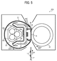
- FIG. 5 a description is provided of a construction of a fixing device 20S according to a second exemplary embodiment.
- FIG. 5 is a vertical cross-sectional view of the fixing device 20S.
- the fixing device 20S depicted in FIG. 5 includes three halogen heaters 23a, 23b, and 23c that serve as a heater for heating the fixing belt 21.
- Other components of the fixing device 20S are substantially equivalent to the components of the fixing device 20.
- identical reference numerals are assigned to the components of the fixing device 20S that are equivalent to the components of the fixing device 20 and redundant description is omitted.
- the fixing device 20S performs fixing on sheets P of various sizes while maintaining productivity.
- the halogen heaters 23a, 23b, and 23c are filled with an inert gas containing xenon or krypton as a main ingredient.
- the bulge 28 projects from the downstream end of the nip formation pad 26 that is in proximity to the exit of the fixing nip N toward the pressure roller 22.
- the bulge 28 does not press against the pressure roller 22 via the fixing belt 21 and therefore is not produced by contact with the pressure roller 22.
- the bulge 28 facilitates separation of a sheet P from the fixing belt 21.
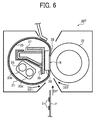
- FIG. 6 a description is provided of a construction of a fixing device 20T according to a third exemplary embodiment.
- FIG. 6 is a vertical cross-sectional view of the fixing device 20T.
- the fixing device 20T depicted in FIG. 6 includes two halogen heaters 23d and 23e that serve as a heater for heating the fixing belt 21.
- the halogen heaters 23d and 23e are filled with an inert gas containing xenon or krypton as a main ingredient.
- the bulge 28 projects from the downstream end of the nip formation pad 26 that is in proximity to the exit of the fixing nip N toward the pressure roller 22.
- the bulge 28 does not press against the pressure roller 22 via the fixing belt 21 and therefore is not produced by contact with the pressure roller 22.
- the bulge 28 facilitates separation of a sheet P from the fixing belt 21.
- a non-conveyance span of the fixing belt 21, outboard from a conveyance span in the axial direction of the fixing belt 21, where the small sheets P are not conveyed may overheat substantially to a temperature above a heat resistant temperature of the fixing belt 21 because the small sheets P do not draw heat from the non-conveyance span of the fixing belt 21.
- the sheet P is conveyed at a conveyance speed higher than a thermal conduction speed at which heat is conducted in the nip formation pad 26 in the longitudinal direction thereof. Accordingly, an amount of heat input to the fixing belt 21 and an amount of heat output from the fixing belt 21 increase per unit time, resulting in substantial overheating of each lateral end of the fixing belt 21 in the axial direction thereof.
- the stay 27 situated inside the loop formed by the fixing belt 21 is susceptible to heat from the halogen heater 23 for an extended period of time.
- the fixing device 20S depicted in FIG. 5 includes the three halogen heaters 23a, 23b, and 23c that have different heat generation spans corresponding to various widths of sheets P, respectively, in the axial direction in the fixing belt 21.
- the fixing device 20T depicted in FIG. 6 includes the two halogen heaters 23d and 23e that have different heat generation spans corresponding to various widths of sheets P, respectively, in the axial direction in the fixing belt 21.
- a fixing device (e.g., the fixing devices 20, 20S, and 20T) includes an endless fixing belt (e.g., the fixing belt 21), a heater (e.g., the halogen heaters 23, 23a, 23b, 23c, 23d, and 23e), a pressure rotator (e.g., the pressure roller 22), and a nip formation pad (e.g., the nip formation pad 26).
- the fixing belt is rotatable in a predetermined direction of rotation (e.g., the rotation direction D21).
- the fixing belt includes an inner circumferential face (e.g., the inner circumferential face 25) applied with or containing a fluorine compound.
- the heater heats the fixing belt.
- the nip formation pad is not rotatable.
- the inner circumferential face of the fixing belt slides over the nip formation pad.
- the pressure rotator is pressed against the nip formation pad via the fixing belt to form a fixing nip (e.g., the fixing nip N) between the fixing belt and the pressure rotator.
- the fixing belt rotates, the inner circumferential face of the fixing belt slides over the nip formation pad.
- the heater includes a glass tube (e.g., the glass tube 23g) filled with an inert gas containing, as a main ingredient, a substance having a first molecular weight greater than a second molecular weight of argon.
- the glass tube of the heater is filled with a halogen gas as the inert gas.
- the heater further includes a filament (e.g., the filament 23f) disposed inside the glass tube.
- the tungsten As a predetermined electric current flows in the filament made of tungsten, the tungsten generates heat and emits light. The tungsten evaporates and bonds with the halogen gas to form a tungsten halide. Convection generated inside the glass tube brings the tungsten halide into contact with the glass tube, causing the tungsten halide to heat the glass tube. Thereafter, the tungsten halide moves to a proximity to the filament again. The tungsten halide separates into a halogen atom and a tungsten atom. The tungsten atom returns to the filament. The tungsten atom bonds with and separates from the floating halogen atom repeatedly.
- the inert gas filling the glass tube of the heater is a gas containing a substance as a main ingredient that has the first molecular weight greater than the second molecular weight of argon, such as xenon and krypton. Accordingly, the glass tube in the aspect A generates the convection less than the glass tube filled with argon, reducing conduction of heat to the glass tube. Consequently, the glass tube is immune from temperature increase and therefore has a temperature lower than a decomposition temperature of 400 degrees centigrade, for example, of the fluorine compound. Even if a controller fails to control power supply to the heater, the temperature of the glass tube does not reach the decomposition temperature of the fluorine compound or higher. Accordingly, even if the fluorine compound adheres to a surface of the glass tube of the heater, the fluorine compound adhered to the glass tube does not generate hydrofluoric acid.
- argon such as xenon and krypton
- the inert gas contains xenon or krypton as the main ingredient.
- the inert gas filling the glass tube of the heater contains xenon or krypton having the first molecular weight greater than the second molecular weight of argon. Accordingly, the glass tube in the aspect B reduces the convection of the tungsten halide inside the glass tube, reducing conduction of heat to the glass tube. Consequently, the temperature of the glass tube does not increase, preventing the fluorine compound adhered to the glass tube from generating hydrofluoric acid.
- the fluorine compound is a lubricant interposed between the nip formation pad and the inner circumferential face of the fixing belt.
- the lubricant is fluorine oil or fluorine grease.
- the lubricant is fluorine grease or silicone grease containing fluorine particles as a thickener. Accordingly, the glass tube in the aspect D reduces the convection of the tungsten halide inside the glass tube, reducing conduction of heat to the glass tube. Consequently, the temperature of the glass tube does not increase, preventing the fluorine grease or the silicone grease containing the fluorine particles as the thickener and being adhered to the glass tube from generating hydrofluoric acid.
- the fluorine compound applied to the inner circumferential face of the fixing belt forms an inner circumferential layer of the fixing belt.
- the glass tube in the aspect E reduces the convection of the tungsten halide inside the glass tube, reducing conduction of heat to the glass tube. Consequently, temperature increase of the glass tube is suppressed. Even if the fluorine compound contained in the inner circumferential layer of the fixing belt generates abrasion powder while the fixing belt slides over the nip formation pad and the abrasion powder adheres to the glass tube, the abrasion powder does not generate hydrofluoric acid.
- an image forming apparatus (e.g., the image forming apparatus 1) includes an image forming device (e.g., the image forming devices 4Y, 4M, 4C, and 4K) to form a toner image on an image bearer (e.g., the photoconductor 5); a transfer device (e.g., the transfer device 3) to transfer the toner image formed on the image bearer onto a recording medium (e.g., a sheet P); and a fixing device (e.g., the fixing devices 20, 20S, and 20T) in the aspect A, B, C, D, or E to fix the toner image on the recording medium.
- the image forming apparatus reduces generation of hydrofluoric acid and enhances safety of an environment where the image forming apparatus is located.
- the fixing belt 21 serves as a fixing belt.
- a fixing film, a fixing sleeve, or the like may be used as a fixing belt.
- the pressure roller 22 serves as a pressure rotator.
- a pressure belt or the like may be used as a pressure rotator.
Landscapes
- Physics & Mathematics (AREA)
- General Physics & Mathematics (AREA)
- Fixing For Electrophotography (AREA)
- Resistance Heating (AREA)
Abstract
Description
- Exemplary aspects of the present disclosure relate to a fixing device and an image forming apparatus, and more particularly, to a fixing device for fixing a toner image on a recording medium and an image forming apparatus incorporating the fixing device.
- Related-art image forming apparatuses, such as copiers, facsimile machines, printers, or multifunction printers having two or more of copying, printing, scanning, facsimile, plotter, and other functions, typically form an image on a recording medium according to image data. Thus, for example, a charger uniformly charges a surface of a photoconductor; an optical writer emits a light beam onto the charged surface of the photoconductor to form an electrostatic latent image on the photoconductor according to the image data; a developing device supplies toner to the electrostatic latent image formed on the photoconductor to render the electrostatic latent image visible as a toner image; the toner image is directly transferred from the photoconductor onto a recording medium or is indirectly transferred from the photoconductor onto a recording medium via an intermediate transfer belt; finally, a fixing device applies heat and pressure to the recording medium bearing the toner image to fix the toner image on the recording medium, thus forming the image on the recording medium.
- Such fixing device may include a fixing rotator, such as a fixing roller, a fixing belt, and a fixing film, heated by a heater and a pressure rotator, such as a pressure roller and a pressure belt, pressed against the fixing rotator to form a fixing nip therebetween, through which a recording medium bearing a toner image is conveyed. As the recording medium bearing the toner image is conveyed through the fixing nip, the fixing rotator and the pressure rotator apply heat and pressure to the recording medium, melting and fixing the toner image on the recording medium.
- One example of the fixing device includes a rotatable, endless fixing belt, a stationary nip formation pad, and a pressure roller pressed against the nip formation pad via the fixing belt to form a fixing nip between the fixing belt and the pressure roller. As the fixing belt rotates, an inner circumferential surface of the fixing belt slides over the nip formation pad frictionally. The nip formation pad has a slide face over which the fixing belt slides. The slide face is coated with a fluorine compound to reduce friction between the nip formation pad and the fixing belt. A halogen heater is disposed opposite the inner circumferential surface of the fixing belt. The halogen heater includes a glass tube filled with argon as an inert gas.
- A controller may suffer from malfunction and may fail to control power supply to the halogen heater, causing the halogen heater to overheat the fixing belt. To address this failure, a safety device such as a thermal fuse and a thermo switch incorporated in an energizing circuit of the halogen heater mechanically blocks power supply to the halogen heater compulsorily, thus preventing overheating of the fixing device. However, since the fixing device is configured to heat the fixing belt to a predetermined temperature quickly, a surface temperature of the glass tube of the halogen heater may increase to a temperature of 400 degrees centigrade or higher instantaneously before the safety device blocks power supply to the halogen heater compulsorily. As the fixing belt slides over the nip formation pad, the fixing belt scrapes the fluorine compound off the nip formation pad. The scraped fluorine compound adheres to a surface of the glass tube of the halogen heater. When the halogen heater heats the fluorine compound adhered to the surface of the glass tube to the temperature of 400 degrees centigrade or higher, the fluorine compound starts decomposing to generate a fluorine gas. The fluorine gas may react with moisture in an atmosphere, generating noxious hydrofluoric acid.
- It is a general object of the present disclosure to provide an improved and useful fixing device in which the above-mentioned problems are eliminated. In order to achieve the above-mentioned object, there is provided a fixing device according to claim 1. Advantageous embodiments are defined by the dependent claims. Advantageously, the fixing device includes a fixing belt being endless and rotatable in a predetermined direction of rotation. The fixing belt includes an inner circumferential face applied with a fluorine compound. A nip formation pad is not rotatable. The inner circumferential face of the fixing belt slides over the nip formation pad. A pressure rotator presses against the nip formation pad via the fixing belt to form a fixing nip between the fixing belt and the pressure rotator. At least one heater heats the fixing belt. The heater includes a glass tube filled with an inert gas containing, as a main ingredient, a substance having a first molecular weight greater than a second molecular weight of argon.
- Accordingly, even if the fluorine compound adheres to a surface of the glass tube of the heater, the fluorine compound adhered to the glass tube does not generate hydrofluoric acid.
- Advantageously, the image forming apparatus includes the fixing device described above.
- A more complete appreciation of the disclosure and the many attendant advantages thereof will be readily obtained as the same becomes better understood by reference to the following detailed description when considered in connection with the accompanying drawings, wherein:
-
FIG. 1 is a schematic vertical cross-sectional view of an image forming apparatus according to an exemplary embodiment of the present disclosure; -
FIG. 2 is a vertical cross-sectional view of a fixing device according to a first exemplary embodiment of the present disclosure that is incorporated in the image forming apparatus depicted inFIG. 1 ; -
FIG. 3 is a cross-sectional view of a halogen heater incorporated in the fixing device depicted inFIG. 2 ; -
FIG. 4 is a graph illustrating temperature increase of a glass tube of the halogen heater depicted inFIG. 3 ; -
FIG. 5 is a vertical cross-sectional view of a fixing device according to a second exemplary embodiment of the present disclosure that is installable in the image forming apparatus depicted inFIG. 1 ; and -
FIG. 6 is a vertical cross-sectional view of a fixing device according to a third exemplary embodiment of the present disclosure that is installable in the image forming apparatus depicted inFIG. 1 . - In describing exemplary embodiments illustrated in the drawings, specific terminology is employed for the sake of clarity. However, the disclosure of this specification is not intended to be limited to the specific terminology so selected and it is to be understood that each specific element includes all technical equivalents that operate in a similar manner and achieve a similar result.
- Referring now to the drawings, wherein like reference numerals designate identical or corresponding parts throughout the several views, in particular to
FIG. 1 , an image forming apparatus 1 according to an exemplary embodiment of the present disclosure is explained. -
FIG. 1 is a schematic vertical cross-sectional view of the image forming apparatus 1. The image forming apparatus 1 may be a copier, a facsimile machine, a printer, a multifunction peripheral or a multifunction printer (MFP) having at least one of copying, printing, scanning, facsimile, and plotter functions, or the like. According to this exemplary embodiment, the image forming apparatus 1 is a color laser printer that forms color and monochrome toner images on a recording medium by electrophotography. Alternatively, the image forming apparatus 1 may be a monochrome printer that forms a monochrome toner image on a recording medium. - Referring to
FIG. 1 , a description is provided of a construction of the image forming apparatus 1. - As illustrated in
FIG. 1 , the image forming apparatus 1 includes fourimage forming devices image forming devices image forming devices - For example, each of the
image forming devices shaped photoconductor 5 serving as an image bearer or a latent image bearer that bears an electrostatic latent image and a resultant toner image; acharger 6 that charges an outer circumferential surface of thephotoconductor 5; a developingdevice 7 that supplies toner to the electrostatic latent image formed on the outer circumferential surface of thephotoconductor 5, thus visualizing the electrostatic latent image as a toner image; and a cleaner 8 that cleans the outer circumferential surface of thephotoconductor 5. -
FIG. 1 illustrates reference numerals assigned to thephotoconductor 5, thecharger 6, the developingdevice 7, and the cleaner 8 of theimage forming device 4K that forms a black toner image. However, reference numerals for theimage forming devices - Below the
image forming devices exposure device 9 that exposes the outer circumferential surface of therespective photoconductors 5 with laser beams. For example, theexposure device 9, constructed of a light source, a polygon mirror, an f-θ lens, reflection mirrors, and the like, emits a laser beam onto the outer circumferential surface of therespective photoconductors 5 according to image data sent from an external device such as a client computer. - Above the
image forming devices transfer device 3. For example, thetransfer device 3 includes anintermediate transfer belt 30 serving as a transferor, fourprimary transfer rollers 31 serving as primary transferors, and asecondary transfer roller 36 serving as a secondary transferor. Thetransfer device 3 further includes a secondarytransfer backup roller 32, acleaning backup roller 33, atension roller 34, and abelt cleaner 35. - The
intermediate transfer belt 30 is an endless belt stretched taut across the secondarytransfer backup roller 32, thecleaning backup roller 33, and thetension roller 34. As a driver drives and rotates the secondarytransfer backup roller 32 counterclockwise inFIG. 1 , the secondarytransfer backup roller 32 rotates theintermediate transfer belt 30 counterclockwise inFIG. 1 in a rotation direction A by friction therebetween. - The four
primary transfer rollers 31 sandwich theintermediate transfer belt 30 together with the fourphotoconductors 5, forming four primary transfer nips between theintermediate transfer belt 30 and thephotoconductors 5, respectively. Theprimary transfer rollers 31 are coupled to a power supply that applies at least one of a predetermined direct current (DC) voltage and a predetermined alternating current (AC) voltage thereto. - The
secondary transfer roller 36 sandwiches theintermediate transfer belt 30 together with the secondarytransfer backup roller 32, forming a secondary transfer nip between thesecondary transfer roller 36 and theintermediate transfer belt 30. Similar to theprimary transfer rollers 31, thesecondary transfer roller 36 is coupled to the power supply that applies at least one of a predetermined direct current (DC) voltage and a predetermined alternating current (AC) voltage thereto. - The
belt cleaner 35 includes a cleaning brush and a cleaning blade that contact an outer circumferential surface of theintermediate transfer belt 30. A waste toner drain tube extending from thebelt cleaner 35 to an inlet of a waste toner container conveys waste toner collected from theintermediate transfer belt 30 by thebelt cleaner 35 to the waste toner container. - A
bottle holder 2 situated in an upper portion of the image forming apparatus 1 accommodates fourtoner bottles devices 7 of theimage forming devices toner bottles devices 7 through toner supply tubes interposed between thetoner bottles devices 7, respectively. - In a lower portion of the image forming apparatus 1 are a
paper tray 10 that loads a plurality of sheets P serving as recording media and a feed roller 11 that picks up and feeds a sheet P from thepaper tray 10 toward the secondary transfer nip formed between thesecondary transfer roller 36 and theintermediate transfer belt 30. The sheets P may be thick paper, postcards, envelopes, plain paper, thin paper, coated paper, art paper, tracing paper, overhead projector (OHP) transparencies, and the like. Optionally, a bypass tray that loads thick paper, postcards, envelopes, thin paper, coated paper, art paper, tracing paper, OHP transparencies, and the like may be attached to the image forming apparatus 1. - A conveyance path R extends from the feed roller 11 to an output roller pair 13 to convey the sheet P picked up from the
paper tray 10 onto an outside of the image forming apparatus 1 through the secondary transfer nip. The conveyance path R is provided with aregistration roller pair 12 located below the secondary transfer nip formed between thesecondary transfer roller 36 and theintermediate transfer belt 30, that is, upstream from the secondary transfer nip in a sheet conveyance direction DP. Theregistration roller pair 12 serving as a conveyor conveys the sheet P conveyed from the feed roller 11 toward the secondary transfer nip. - The conveyance path R is further provided with a fixing
device 20 located above the secondary transfer nip, that is, downstream from the secondary transfer nip in the sheet conveyance direction DP. The fixingdevice 20 fixes an unfixed toner image transferred from theintermediate transfer belt 30 onto the sheet P conveyed from the secondary transfer nip on the sheet P. The conveyance path R is further provided with the output roller pair 13 located above the fixingdevice 20, that is, downstream from the fixingdevice 20 in the sheet conveyance direction DP. The output roller pair 13 ejects the sheet P bearing the fixed toner image onto the outside of the image forming apparatus 1, that is, anoutput tray 14 disposed atop the image forming apparatus 1. Theoutput tray 14 stocks the sheet P ejected by the output roller pair 13. - Referring to
FIG. 1 , a description is provided of an image forming operation performed by the image forming apparatus 1 having the construction described above to form a full color toner image on a sheet P. - As a print job starts, a driver drives and rotates the
photoconductors 5 of theimage forming devices FIG. 1 in a rotation direction D5. Thechargers 6 uniformly charge the outer circumferential surface of therespective photoconductors 5 at a predetermined polarity. Theexposure device 9 emits laser beams onto the charged outer circumferential surface of therespective photoconductors 5 according to yellow, magenta, cyan, and black image data constructing color image data sent from the external device, respectively, thus forming electrostatic latent images thereon. The image data used to expose therespective photoconductors 5 is monochrome image data produced by decomposing a desired full color image into yellow, magenta, cyan, and black image data. The developingdevices 7 supply yellow, magenta, cyan, and black toners to the electrostatic latent images formed on thephotoconductors 5, visualizing the electrostatic latent images as yellow, magenta, cyan, and black toner images, respectively. - Simultaneously, as the print job starts, the secondary
transfer backup roller 32 is driven and rotated counterclockwise inFIG. 1 , rotating theintermediate transfer belt 30 in the rotation direction A by friction therebetween. The power supply applies a constant voltage or a constant current control voltage having a polarity opposite a polarity of the charged toner to theprimary transfer rollers 31, creating a transfer electric field at the respective primary transfer nips formed between thephotoconductors 5 and theprimary transfer rollers 31. - When the yellow, magenta, cyan, and black toner images formed on the
photoconductors 5 reach the primary transfer nips, respectively, in accordance with rotation of thephotoconductors 5, the yellow, magenta, cyan, and black toner images are primarily transferred from thephotoconductors 5 onto theintermediate transfer belt 30 by the transfer electric field created at the primary transfer nips such that the yellow, magenta, cyan, and black toner images are superimposed successively on a same position on theintermediate transfer belt 30. Thus, a full color toner image is formed on the outer circumferential surface of theintermediate transfer belt 30. After the primary transfer of the yellow, magenta, cyan, and black toner images from thephotoconductors 5 onto theintermediate transfer belt 30, the cleaners 8 remove residual toner failed to be transferred onto theintermediate transfer belt 30 and therefore remaining on thephotoconductors 5 therefrom, respectively. Thereafter, dischargers discharge the outer circumferential surface of therespective photoconductors 5, initializing the surface potential thereof. - On the other hand, the feed roller 11 disposed in the lower portion of the image forming apparatus 1 is driven and rotated to feed a sheet P from the
paper tray 10 toward theregistration roller pair 12 through the conveyance path R. Theregistration roller pair 12 conveys the sheet P sent to the conveyance path R by the feed roller 11 to the secondary transfer nip formed between thesecondary transfer roller 36 and theintermediate transfer belt 30 at a proper time. Thesecondary transfer roller 36 is applied with a transfer voltage having a polarity opposite a polarity of the charged yellow, magenta, cyan, and black toners constructing the full color toner image formed on theintermediate transfer belt 30, thus creating a transfer electric field at the secondary transfer nip. - As the yellow, magenta, cyan, and black toner images constructing the full color toner image on the
intermediate transfer belt 30 reach the secondary transfer nip in accordance with rotation of theintermediate transfer belt 30, the transfer electric field created at the secondary transfer nip secondarily transfers the yellow, magenta, cyan, and black toner images from theintermediate transfer belt 30 onto the sheet P collectively. After the secondary transfer of the full color toner image from theintermediate transfer belt 30 onto the sheet P, thebelt cleaner 35 removes residual toner failed to be transferred onto the sheet P and therefore remaining on theintermediate transfer belt 30 therefrom. The removed toner is conveyed and collected into the waste toner container. - Thereafter, the sheet P bearing the full color toner image is conveyed to the fixing
device 20 that fixes the full color toner image on the sheet P. Then, the sheet P bearing the fixed full color toner image is ejected by the output roller pair 13 onto the outside of the image forming apparatus 1, that is, theoutput tray 14 that stocks the sheet P. - The above describes the image forming operation of the image forming apparatus 1 to form the full color toner image on the sheet P. Alternatively, the image forming apparatus 1 may form a monochrome toner image by using any one of the four
image forming devices image forming devices - Referring to
FIGS. 2 and3 , a description is provided of a construction of the fixingdevice 20 according to a first exemplary embodiment that is incorporated in the image forming apparatus 1 having the construction described above. -
FIG. 2 is a vertical cross-sectional view of the fixingdevice 20. As illustrated inFIG. 2 , the fixing device 20 (e.g., a fuser or a fusing unit) includes a fixingbelt 21 formed into a loop, ahalogen heater 23, anip formation pad 26, astay 27, and areflector 29 that are disposed inside the loop formed by the fixingbelt 21 and apressure roller 22 disposed outside the loop formed by the fixingbelt 21. The fixingbelt 21 includes an innercircumferential face 25. The fixingbelt 21 and the components disposed inside the fixingbelt 21, that is, thehalogen heater 23, thenip formation pad 26, thestay 27, and thereflector 29, may construct abelt unit 21U separably coupled to thepressure roller 22. - The fixing
belt 21 serves as a fixing rotator or a fixing member rotatable in a rotation direction D21. Thepressure roller 22 serves as a pressure rotator rotatable in a rotation direction D22. Thehalogen heater 23 serving as a heater or a heat source is disposed inside the loop formed by the fixingbelt 21. Thehalogen heater 23 emits heat or light that irradiates the innercircumferential face 25 of the fixingbelt 21 directly, heating the fixingbelt 21 with radiant heat or light. -
FIG. 3 is a cross-sectional view of thehalogen heater 23. As illustrated inFIG. 3 , thehalogen heater 23 is a halogen lamp including aglass tube 23g filled with an inert gas containing xenon or krypton as a main ingredient. A molecular weight of each of xenon and krypton is greater than a molecular weight of argon. - As illustrated in
FIG. 2 , thenip formation pad 26 is disposed inside the loop formed by the fixingbelt 21 and disposed opposite thepressure roller 22 via the fixingbelt 21. Thenip formation pad 26 presses against thepressure roller 22 via the fixingbelt 21 to form a fixing nip N between the fixingbelt 21 and thepressure roller 22. As a sheet P serving as a recording medium bearing a toner image T is conveyed through the fixing nip N, the fixingbelt 21 heated by thehalogen heater 23 and thepressure roller 22 fix the toner image T on the sheet P under heat and pressure. As the fixingbelt 21 rotates in the rotation direction D21, the innercircumferential face 25 of the fixingbelt 21 slides over thenip formation pad 26 directly or indirectly via a slide sheet interposed between the fixingbelt 21 and thenip formation pad 26. The innercircumferential face 25 of the fixingbelt 21 is applied with a lubricant such as fluorine oil and fluorine grease to reduce friction between thenip formation pad 26 and the fixingbelt 21. The lubricant is fluorine grease or silicone grease containing fluorine particles as a thickener. The innercircumferential face 25 of the fixingbelt 21, which slides over thenip formation pad 26, may be applied with a fluorine compound such that the fluorine compound forms an inner circumferential layer of the fixingbelt 21. - As illustrated in
FIG. 2 , the fixing nip N is planar. Alternatively, the fixing nip N may be contoured into a recess, a curve, or other shapes. If the fixing nip N is recessed with respect to thepressure roller 22, the recessed fixing nip N directs a leading edge of the sheet P toward thepressure roller 22 as the sheet P is discharged from the fixing nip N, facilitating separation of the sheet P from the fixingbelt 21 and suppressing jamming of the sheet P. - A detailed description is now given of a construction of the fixing
belt 21. - The fixing
belt 21 is an endless belt or film made of metal such as nickel and SUS stainless steel or resin such as polyimide. The fixingbelt 21 is constructed of a base layer and a release layer. The release layer serving as an outer surface layer is made of tetrafluoroethylene-perfluoroalkylvinylether copolymer (PFA), polytetrafluoroethylene (PTFE), or the like to facilitate separation of toner of the toner image T on the sheet P from the fixingbelt 21 and prevent the toner from adhering to the fixingbelt 21. An elastic layer may be sandwiched between the base layer and the release layer and made of silicone rubber or the like. If the fixingbelt 21 does not incorporate the elastic layer, the fixingbelt 21 has a decreased thermal capacity that improves fixing property of being heated quickly to a predetermined fixing temperature at which the toner image T is fixed on the sheet P. However, as thepressure roller 22 and the fixingbelt 21 sandwich and press the unfixed toner image T on the sheet P passing through the fixing nip N, slight surface asperities of the fixingbelt 21 may be transferred onto the toner image T on the sheet P, resulting in variation in gloss of the solid toner image T that may appear as a faulty orange peel image on the sheet P. To address this circumstance, the elastic layer made of silicone rubber has a thickness not smaller than 100 micrometers. As the elastic layer deforms, the elastic layer absorbs slight surface asperities of the fixingbelt 21, preventing formation of the faulty orange peel image. - A detailed description is now given of a configuration of the
stay 27 and thereflector 29. - The
stay 27 serving as a support that supports thenip formation pad 26 is situated inside the loop formed by the fixingbelt 21. As thenip formation pad 26 receives pressure from thepressure roller 22, thestay 27 supports thenip formation pad 26 to prevent bending of thenip formation pad 26 and produce an even nip length in the sheet conveyance direction DP throughout the entire width of the fixingbelt 21 in an axial direction thereof parallel to a longitudinal direction of thenip formation pad 26. Thestay 27 is made of metal to attain rigidity. Thestay 27 is mounted on and secured to side plates at both lateral ends of thestay 27 in a longitudinal direction thereof parallel to the axial direction of the fixingbelt 21, respectively, thus being positioned inside the fixingdevice 20. - Since the
nip formation pad 26 has a complex shape, thenip formation pad 26 is made of heat resistant resin and manufactured by injection molding. For example, the heat resistant resin may be liquid crystal polymer (LCP) having a heat resistant temperature of about 330 degrees centigrade, polyetherketone (PEK) having a heat resistant temperature of about 350 degrees centigrade, or the like. - The
reflector 29 interposed between thehalogen heater 23 and thestay 27 reflects light or heat radiated from thehalogen heater 23 to thereflector 29 toward the fixingbelt 21, preventing thestay 27 from being heated by thehalogen heater 23 and thereby reducing waste of energy. Alternatively, instead of thereflector 29, an opposed face of thestay 27 disposed opposite thehalogen heater 23 may be treated with insulation or mirror finish to reflect light or heat radiated from thehalogen heater 23 to thestay 27 toward the fixingbelt 21. - A detailed description is now given of a construction of the
pressure roller 22. - The
pressure roller 22 is constructed of a cored bar, an elastic rubber layer coating the cored bar, and a surface release layer coating the elastic rubber layer and made of PFA or PTFE to facilitate separation of the sheet P from thepressure roller 22. As a driving force generated by a driver (e.g., a motor) situated inside the image forming apparatus 1 depicted inFIG. 1 is transmitted to thepressure roller 22 through a gear train, thepressure roller 22 rotates clockwise inFIG. 2 in the rotation direction D22. Alternatively, the driver may also be coupled to the fixingbelt 21 to drive and rotate the fixingbelt 21. A spring or the like presses thepressure roller 22 against thenip formation pad 26 via the fixingbelt 21. As the spring presses and deforms the elastic rubber layer of thepressure roller 22, thepressure roller 22 produces the fixing nip N having the predetermined length in the sheet conveyance direction DP. - The
pressure roller 22 may be a hollow roller or a solid roller. If thepressure roller 22 is a hollow roller, a heater such as a halogen heater may be disposed inside the hollow roller. The elastic rubber layer may be made of solid rubber. Alternatively, if no heater is situated inside thepressure roller 22, the elastic rubber layer may be made of sponge rubber. The sponge rubber is more preferable than the solid rubber because the sponge rubber has an enhanced insulation that decreases an amount of heat drawn from the fixingbelt 21. - As the
pressure roller 22 rotates in the rotation direction D22, the fixingbelt 21 rotates counterclockwise inFIG. 2 in the rotation direction D21 in accordance with rotation of thepressure roller 22 by friction therebetween. As the driver drives and rotates thepressure roller 22, a driving force of the driver is transmitted from thepressure roller 22 to the fixingbelt 21 at the fixing nip N, thus rotating the fixingbelt 21 by friction between thepressure roller 22 and the fixingbelt 21. At the fixing nip N, the fixingbelt 21 rotates as the fixingbelt 21 is sandwiched between thepressure roller 22 and thenip formation pad 26; at a circumferential span of the fixingbelt 21 other than the fixing nip N, the fixingbelt 21 rotates while the fixingbelt 21 is guided by a flange at each lateral end of the fixingbelt 21 in the axial direction thereof. As the sheet P is conveyed through the fixing nip N, the fixingbelt 21 and thepressure roller 22 apply heat and pressure to the sheet P, fixing the toner image T on the sheet P. With the construction described above, the fixingdevice 20 attaining quick warm-up is manufactured at reduced costs. - A
bulge 28 projects from a downstream end of thenip formation pad 26 in the sheet conveyance direction DP, that is, an exit of the fixing nip N, toward thepressure roller 22. Thebulge 28 does not press against thepressure roller 22 via the fixingbelt 21 and therefore is not produced by contact with thepressure roller 22. Thebulge 28 lifts the sheet P conveyed through the exit of the fixing nip N from the fixingbelt 21, facilitating separation of the sheet P from the fixingbelt 21. -
FIG. 4 is a graph illustrating a result of an experiment, that is, temperature increase of a surface of theglass tube 23g of thehalogen heater 23 that is filled with a xenon gas instead of an argon gas as an inert gas.FIG. 4 illustrates a curve Ar attained with a glass tube filled with the argon gas and a curve Xe attained with theglass tube 23g filled with the xenon gas. - The result of the experiment indicates that the temperature of the glass tube filled with the argon gas exceeds 400 degrees centigrade when 110 seconds elapse after a fixing operation starts. Conversely, even when 110 seconds elapse after the fixing operation starts, the temperature of the
glass tube 23g filled with the xenon gas is retained at about 350 degrees centigrade that is lower than 400 degrees centigrade at which hydrofluoric acid generates. Under a heat generation mechanism of thehalogen heater 23, as the inert gas fills a space inside theglass tube 23g, pressure of the inert gas suppresses evaporation of tungsten used in afilament 23f depicted inFIG. 3 . The evaporated tungsten collides with molecules of the inert gas and does not propagate rectilinearly, increasing vapor pressure of peripheral tungsten. Accordingly, evaporation of the tungsten is suppressed, resulting in the extended life of thehalogen heater 23. - Such advantage of the inert gas enhances as the molecular weight increases. As the molecular weight of the inert gas increases, convection decreases to draw a decreased amount of heat from the
filament 23f. Accordingly, a decreased amount of heat is conducted from thefilament 23f to theglass tube 23g through the inert gas, suppressing temperature increase of theglass tube 23g. - The inert gas used in the
halogen heater 23 includes helium, neon, argon, krypton, xenon, and radon which are enumerated according to the molecular weight. For example, helium has a smallest molecular weight. Radon has a greatest molecular weight. Accordingly, krypton and xenon are advantageous over argon. Xenon is advantageous over krypton. - The
glass tube 23g of thehalogen heater 23 is filled with the inert gas having a molecular weight greater than the molecular weight of argon to suppress temperature increase of theglass tube 23g. Even if the controller fails to control thehalogen heater 23 properly and thehalogen heater 23 suffers from overheating, the inert gas filling theglass tube 23g suppresses generation of hydrofluoric acid. Radon is unpractical and avoided because radon is a radioactive gas having a short half-life. - Referring to
FIG. 5 , a description is provided of a construction of afixing device 20S according to a second exemplary embodiment. -
FIG. 5 is a vertical cross-sectional view of thefixing device 20S. Unlike the fixingdevice 20 depicted inFIG. 2 that includes thesingle halogen heater 23, the fixingdevice 20S depicted inFIG. 5 includes threehalogen heaters belt 21. Other components of thefixing device 20S are substantially equivalent to the components of the fixingdevice 20. Hence, identical reference numerals are assigned to the components of thefixing device 20S that are equivalent to the components of the fixingdevice 20 and redundant description is omitted. - With the increased number of the
halogen heaters device 20S performs fixing on sheets P of various sizes while maintaining productivity. Thehalogen heaters bulge 28 projects from the downstream end of thenip formation pad 26 that is in proximity to the exit of the fixing nip N toward thepressure roller 22. Thebulge 28 does not press against thepressure roller 22 via the fixingbelt 21 and therefore is not produced by contact with thepressure roller 22. Thebulge 28 facilitates separation of a sheet P from the fixingbelt 21. - Referring to
FIG. 6 , a description is provided of a construction of afixing device 20T according to a third exemplary embodiment. -
FIG. 6 is a vertical cross-sectional view of the fixingdevice 20T. Unlike the fixingdevice 20 depicted inFIG. 2 that includes thesingle halogen heater 23, the fixingdevice 20T depicted inFIG. 6 includes twohalogen heaters belt 21. Thehalogen heaters bulge 28 projects from the downstream end of thenip formation pad 26 that is in proximity to the exit of the fixing nip N toward thepressure roller 22. Thebulge 28 does not press against thepressure roller 22 via the fixingbelt 21 and therefore is not produced by contact with thepressure roller 22. Thebulge 28 facilitates separation of a sheet P from the fixingbelt 21. - When a plurality of small sheets P having a width smaller than a heat generation span of the
halogen heater 23 depicted inFIG. 2 is conveyed over the fixingbelt 21 continuously, a non-conveyance span of the fixingbelt 21, outboard from a conveyance span in the axial direction of the fixingbelt 21, where the small sheets P are not conveyed may overheat substantially to a temperature above a heat resistant temperature of the fixingbelt 21 because the small sheets P do not draw heat from the non-conveyance span of the fixingbelt 21. For example, in the image forming apparatus 1 capable of high speed printing, the sheet P is conveyed at a conveyance speed higher than a thermal conduction speed at which heat is conducted in thenip formation pad 26 in the longitudinal direction thereof. Accordingly, an amount of heat input to the fixingbelt 21 and an amount of heat output from the fixingbelt 21 increase per unit time, resulting in substantial overheating of each lateral end of the fixingbelt 21 in the axial direction thereof. - Similarly, the
stay 27 situated inside the loop formed by the fixingbelt 21 is susceptible to heat from thehalogen heater 23 for an extended period of time. - To address those circumstances, the fixing
device 20S depicted inFIG. 5 includes the threehalogen heaters belt 21. The fixingdevice 20T depicted inFIG. 6 includes the twohalogen heaters belt 21. - The exemplary embodiments described above are one example and attain advantages below in a plurality of aspects A to F.
- A description is provided of advantages of the fixing
devices - As illustrated in
FIGS. 2 ,5 , and6 , a fixing device (e.g., the fixingdevices halogen heaters - As illustrated in
FIG. 3 , the heater includes a glass tube (e.g., theglass tube 23g) filled with an inert gas containing, as a main ingredient, a substance having a first molecular weight greater than a second molecular weight of argon. The glass tube of the heater is filled with a halogen gas as the inert gas. The heater further includes a filament (e.g., thefilament 23f) disposed inside the glass tube. - As a predetermined electric current flows in the filament made of tungsten, the tungsten generates heat and emits light. The tungsten evaporates and bonds with the halogen gas to form a tungsten halide. Convection generated inside the glass tube brings the tungsten halide into contact with the glass tube, causing the tungsten halide to heat the glass tube. Thereafter, the tungsten halide moves to a proximity to the filament again. The tungsten halide separates into a halogen atom and a tungsten atom. The tungsten atom returns to the filament. The tungsten atom bonds with and separates from the floating halogen atom repeatedly.
- In the aspect A, the inert gas filling the glass tube of the heater is a gas containing a substance as a main ingredient that has the first molecular weight greater than the second molecular weight of argon, such as xenon and krypton. Accordingly, the glass tube in the aspect A generates the convection less than the glass tube filled with argon, reducing conduction of heat to the glass tube. Consequently, the glass tube is immune from temperature increase and therefore has a temperature lower than a decomposition temperature of 400 degrees centigrade, for example, of the fluorine compound. Even if a controller fails to control power supply to the heater, the temperature of the glass tube does not reach the decomposition temperature of the fluorine compound or higher. Accordingly, even if the fluorine compound adheres to a surface of the glass tube of the heater, the fluorine compound adhered to the glass tube does not generate hydrofluoric acid.
- A description is provided of advantages of the fixing
devices - In the aspect A, the inert gas contains xenon or krypton as the main ingredient. The inert gas filling the glass tube of the heater contains xenon or krypton having the first molecular weight greater than the second molecular weight of argon. Accordingly, the glass tube in the aspect B reduces the convection of the tungsten halide inside the glass tube, reducing conduction of heat to the glass tube. Consequently, the temperature of the glass tube does not increase, preventing the fluorine compound adhered to the glass tube from generating hydrofluoric acid.
- A description is provided of advantages of the fixing
devices - In the aspect A or B, the fluorine compound is a lubricant interposed between the nip formation pad and the inner circumferential face of the fixing belt. The lubricant is fluorine oil or fluorine grease. Accordingly, the glass tube in the aspect C reduces the convection of the tungsten halide inside the glass tube, reducing conduction of heat to the glass tube. Consequently, the temperature of the glass tube does not increase, preventing the fluorine oil or the fluorine grease adhered to the glass tube from generating hydrofluoric acid.
- A description is provided of advantages of the fixing
devices - In the aspect C, the lubricant is fluorine grease or silicone grease containing fluorine particles as a thickener. Accordingly, the glass tube in the aspect D reduces the convection of the tungsten halide inside the glass tube, reducing conduction of heat to the glass tube. Consequently, the temperature of the glass tube does not increase, preventing the fluorine grease or the silicone grease containing the fluorine particles as the thickener and being adhered to the glass tube from generating hydrofluoric acid.
- A description is provided of advantages of the fixing
devices - In the aspect A or B, the fluorine compound applied to the inner circumferential face of the fixing belt forms an inner circumferential layer of the fixing belt. Accordingly, the glass tube in the aspect E reduces the convection of the tungsten halide inside the glass tube, reducing conduction of heat to the glass tube. Consequently, temperature increase of the glass tube is suppressed. Even if the fluorine compound contained in the inner circumferential layer of the fixing belt generates abrasion powder while the fixing belt slides over the nip formation pad and the abrasion powder adheres to the glass tube, the abrasion powder does not generate hydrofluoric acid.
- A description is provided of advantages of the fixing
devices - As illustrated in
FIG. 1 , an image forming apparatus (e.g., the image forming apparatus 1) includes an image forming device (e.g., theimage forming devices devices - According to the exemplary embodiments described above, the fixing
belt 21 serves as a fixing belt. Alternatively, a fixing film, a fixing sleeve, or the like may be used as a fixing belt. Further, thepressure roller 22 serves as a pressure rotator. Alternatively, a pressure belt or the like may be used as a pressure rotator.
Claims (11)
- A fixing device (20) comprising:a fixing belt (21) being endless and rotatable in a predetermined direction of rotation (D21),the fixing belt (21) including an inner circumferential face (25) applied with a fluorine compound;a nip formation pad (26) not rotatable, the nip formation pad (26) over which the inner circumferential face (25) of the fixing belt (21) slides;a pressure rotator (22) to press against the nip formation pad (26) via the fixing belt (21) to form a fixing nip (N) between the fixing belt (21) and the pressure rotator (22); andat least one heater (23) to heat the fixing belt (21), the heater (23) including a glass tube (23g) filled with an inert gas containing, as a main ingredient, a substance having a first molecular weight greater than a second molecular weight of argon.
- The fixing device (20) according to claim 1,
wherein the heater (23) includes a halogen heater (23). - The fixing device (20) according to claim 1 or 2,
wherein the substance as the main ingredient contains one of xenon and krypton. - The fixing device (20) according to any one of claims 1 to 3,
wherein the fluorine compound is a lubricant interposed between the nip formation pad (26) and the inner circumferential face (25) of the fixing belt (21). - The fixing device (20) according to claim 4,
wherein the lubricant is one of fluorine oil and fluorine grease. - The fixing device (20) according to claim 4 or 5,
wherein the lubricant is one of fluorine grease and silicone grease that contains fluorine particles as a thickener. - The fixing device (20) according to any one of claims 1 to 3,
wherein the fluorine compound applied to the inner circumferential face (25) of the fixing belt (21) forms an inner circumferential layer (25) of the fixing belt (21). - The fixing device (20) according to any one of claims 1 to 7,
wherein the at least one heater (23) includes two halogen heaters (23d, 23e). - The fixing device (20) according to any one of claims 1 to 7,
wherein the at least one heater (23) includes three halogen heaters (23a, 23b, 23c). - The fixing device (20) according to any one of claims 1 to 9,
wherein the pressure rotator (22) includes a pressure roller (22). - An image forming apparatus (1) comprising the fixing device (20) according to any one of claims 1 to 10.
Applications Claiming Priority (1)
| Application Number | Priority Date | Filing Date | Title |
|---|---|---|---|
| JP2015211529A JP6631876B2 (en) | 2015-10-28 | 2015-10-28 | Fixing device and image forming device |
Publications (2)
| Publication Number | Publication Date |
|---|---|
| EP3163377A1 true EP3163377A1 (en) | 2017-05-03 |
| EP3163377B1 EP3163377B1 (en) | 2019-05-22 |
Family
ID=56997398
Family Applications (1)
| Application Number | Title | Priority Date | Filing Date |
|---|---|---|---|
| EP16190602.9A Active EP3163377B1 (en) | 2015-10-28 | 2016-09-26 | Fixing device and image forming apparatus |
Country Status (3)
| Country | Link |
|---|---|
| US (1) | US10036986B2 (en) |
| EP (1) | EP3163377B1 (en) |
| JP (1) | JP6631876B2 (en) |
Families Citing this family (4)
| Publication number | Priority date | Publication date | Assignee | Title |
|---|---|---|---|---|
| EP3276430B1 (en) | 2016-07-25 | 2019-09-04 | Ricoh Company, Ltd. | Image forming apparatus |
| JP2018092074A (en) | 2016-12-06 | 2018-06-14 | 株式会社リコー | Fixing apparatus and image forming apparatus |
| JP6794815B2 (en) | 2016-12-16 | 2020-12-02 | 株式会社リコー | Fixing device and image forming device |
| JP2019035887A (en) * | 2017-08-18 | 2019-03-07 | 京セラドキュメントソリューションズ株式会社 | Fixing device and image forming apparatus |
Citations (2)
| Publication number | Priority date | Publication date | Assignee | Title |
|---|---|---|---|---|
| US20020113050A1 (en) * | 1999-10-29 | 2002-08-22 | Jun Yura | Image forming apparatus and fixing device therefor |
| US20150125193A1 (en) * | 2013-11-07 | 2015-05-07 | Kenji Ishii | Fixing device and image forming apparatus |
Family Cites Families (9)
| Publication number | Priority date | Publication date | Assignee | Title |
|---|---|---|---|---|
| JP2001282020A (en) * | 2000-03-31 | 2001-10-12 | Ricoh Co Ltd | Fixing device |
| JP3668149B2 (en) | 2000-03-31 | 2005-07-06 | 株式会社リコー | Fixing device |
| JP4166962B2 (en) | 2001-04-19 | 2008-10-15 | 株式会社リコー | Image forming apparatus |
| JP4002817B2 (en) | 2002-11-20 | 2007-11-07 | 株式会社リコー | Image forming apparatus |
| JP2005317519A (en) * | 2004-03-30 | 2005-11-10 | Canon Inc | Heating apparatus and image forming apparatus |
| JP4708230B2 (en) * | 2006-03-14 | 2011-06-22 | シャープ株式会社 | Fixing apparatus and image forming apparatus |
| JP5365908B2 (en) * | 2008-06-16 | 2013-12-11 | 株式会社リコー | Fixing apparatus and image forming apparatus |
| JP2010217205A (en) | 2009-03-13 | 2010-09-30 | Panasonic Corp | Fixing device |
| US20110085831A1 (en) * | 2009-10-13 | 2011-04-14 | David William Hullman | Fuser for an Image-Forming Apparatus and Method of Using Same |
-
2015
- 2015-10-28 JP JP2015211529A patent/JP6631876B2/en active Active
-
2016
- 2016-09-26 EP EP16190602.9A patent/EP3163377B1/en active Active
- 2016-10-10 US US15/289,439 patent/US10036986B2/en active Active
Patent Citations (2)
| Publication number | Priority date | Publication date | Assignee | Title |
|---|---|---|---|---|
| US20020113050A1 (en) * | 1999-10-29 | 2002-08-22 | Jun Yura | Image forming apparatus and fixing device therefor |
| US20150125193A1 (en) * | 2013-11-07 | 2015-05-07 | Kenji Ishii | Fixing device and image forming apparatus |
Also Published As
| Publication number | Publication date |
|---|---|
| JP2017083632A (en) | 2017-05-18 |
| EP3163377B1 (en) | 2019-05-22 |
| US20170123357A1 (en) | 2017-05-04 |
| JP6631876B2 (en) | 2020-01-15 |
| US10036986B2 (en) | 2018-07-31 |
Similar Documents
| Publication | Publication Date | Title |
|---|---|---|
| US10042295B2 (en) | Fixing device, image forming apparatus, and image forming method | |
| US10082751B2 (en) | Fixing device and image forming apparatus | |
| US9964905B2 (en) | Fixing device and image forming apparatus | |
| US9851667B2 (en) | Fixing device and image forming apparatus | |
| JP6772602B2 (en) | Fixing device and image forming device | |
| US9933730B2 (en) | Fixing device and image forming apparatus | |
| US10168653B2 (en) | Fixing device and image forming apparatus incorporating same | |
| US9989905B2 (en) | Fixing device and image forming apparatus | |
| US10678170B2 (en) | Fixing device and image forming apparatus | |
| US9329542B2 (en) | Fixing device and image forming apparatus | |
| US9778606B2 (en) | Fixing device and image forming apparatus | |
| US9529308B2 (en) | Image forming apparatus and image forming method | |
| EP3163377B1 (en) | Fixing device and image forming apparatus | |
| JP2014164223A (en) | Fixing device and image forming apparatus | |
| JP6888319B2 (en) | Fixing device and image forming device | |
| JP6676958B2 (en) | Fixing device and image forming device | |
| JP6676956B2 (en) | Fixing device and image forming device | |
| JP6888302B2 (en) | Fixing device and image forming device | |
| JP6848370B2 (en) | Fixing device and image forming device | |
| JP6848371B2 (en) | Fixing device and image forming device | |
| JP6753275B2 (en) | Fixing device and image forming device | |
| JP7143664B2 (en) | Fixing device and image forming device | |
| JP6753274B2 (en) | Fixing device and image forming device | |
| JP6819085B2 (en) | Fixing device and image forming device | |
| JP6852370B2 (en) | Fixing device and image forming device |
Legal Events
| Date | Code | Title | Description |
|---|---|---|---|
| PUAI | Public reference made under article 153(3) epc to a published international application that has entered the european phase |
Free format text: ORIGINAL CODE: 0009012 |
|
| STAA | Information on the status of an ep patent application or granted ep patent |
Free format text: STATUS: REQUEST FOR EXAMINATION WAS MADE |
|
| 17P | Request for examination filed |
Effective date: 20160926 |
|
| AK | Designated contracting states |
Kind code of ref document: A1 Designated state(s): AL AT BE BG CH CY CZ DE DK EE ES FI FR GB GR HR HU IE IS IT LI LT LU LV MC MK MT NL NO PL PT RO RS SE SI SK SM TR |
|
| AX | Request for extension of the european patent |
Extension state: BA ME |
|
| GRAP | Despatch of communication of intention to grant a patent |
Free format text: ORIGINAL CODE: EPIDOSNIGR1 |
|
| STAA | Information on the status of an ep patent application or granted ep patent |
Free format text: STATUS: GRANT OF PATENT IS INTENDED |
|
| INTG | Intention to grant announced |
Effective date: 20181220 |
|
| GRAS | Grant fee paid |
Free format text: ORIGINAL CODE: EPIDOSNIGR3 |
|
| GRAA | (expected) grant |
Free format text: ORIGINAL CODE: 0009210 |
|
| STAA | Information on the status of an ep patent application or granted ep patent |
Free format text: STATUS: THE PATENT HAS BEEN GRANTED |
|
| AK | Designated contracting states |
Kind code of ref document: B1 Designated state(s): AL AT BE BG CH CY CZ DE DK EE ES FI FR GB GR HR HU IE IS IT LI LT LU LV MC MK MT NL NO PL PT RO RS SE SI SK SM TR |
|
| REG | Reference to a national code |
Ref country code: GB Ref legal event code: FG4D |
|
| REG | Reference to a national code |
Ref country code: CH Ref legal event code: EP |
|
| REG | Reference to a national code |
Ref country code: IE Ref legal event code: FG4D |
|
| REG | Reference to a national code |
Ref country code: DE Ref legal event code: R096 Ref document number: 602016014209 Country of ref document: DE |
|
| REG | Reference to a national code |
Ref country code: AT Ref legal event code: REF Ref document number: 1136852 Country of ref document: AT Kind code of ref document: T Effective date: 20190615 |
|
| REG | Reference to a national code |
Ref country code: NL Ref legal event code: MP Effective date: 20190522 |
|
| REG | Reference to a national code |
Ref country code: LT Ref legal event code: MG4D |
|
| PG25 | Lapsed in a contracting state [announced via postgrant information from national office to epo] |
Ref country code: FI Free format text: LAPSE BECAUSE OF FAILURE TO SUBMIT A TRANSLATION OF THE DESCRIPTION OR TO PAY THE FEE WITHIN THE PRESCRIBED TIME-LIMIT Effective date: 20190522 Ref country code: ES Free format text: LAPSE BECAUSE OF FAILURE TO SUBMIT A TRANSLATION OF THE DESCRIPTION OR TO PAY THE FEE WITHIN THE PRESCRIBED TIME-LIMIT Effective date: 20190522 Ref country code: AL Free format text: LAPSE BECAUSE OF FAILURE TO SUBMIT A TRANSLATION OF THE DESCRIPTION OR TO PAY THE FEE WITHIN THE PRESCRIBED TIME-LIMIT Effective date: 20190522 Ref country code: PT Free format text: LAPSE BECAUSE OF FAILURE TO SUBMIT A TRANSLATION OF THE DESCRIPTION OR TO PAY THE FEE WITHIN THE PRESCRIBED TIME-LIMIT Effective date: 20190922 Ref country code: NO Free format text: LAPSE BECAUSE OF FAILURE TO SUBMIT A TRANSLATION OF THE DESCRIPTION OR TO PAY THE FEE WITHIN THE PRESCRIBED TIME-LIMIT Effective date: 20190822 Ref country code: HR Free format text: LAPSE BECAUSE OF FAILURE TO SUBMIT A TRANSLATION OF THE DESCRIPTION OR TO PAY THE FEE WITHIN THE PRESCRIBED TIME-LIMIT Effective date: 20190522 Ref country code: NL Free format text: LAPSE BECAUSE OF FAILURE TO SUBMIT A TRANSLATION OF THE DESCRIPTION OR TO PAY THE FEE WITHIN THE PRESCRIBED TIME-LIMIT Effective date: 20190522 Ref country code: SE Free format text: LAPSE BECAUSE OF FAILURE TO SUBMIT A TRANSLATION OF THE DESCRIPTION OR TO PAY THE FEE WITHIN THE PRESCRIBED TIME-LIMIT Effective date: 20190522 Ref country code: LT Free format text: LAPSE BECAUSE OF FAILURE TO SUBMIT A TRANSLATION OF THE DESCRIPTION OR TO PAY THE FEE WITHIN THE PRESCRIBED TIME-LIMIT Effective date: 20190522 |
|
| PG25 | Lapsed in a contracting state [announced via postgrant information from national office to epo] |
Ref country code: LV Free format text: LAPSE BECAUSE OF FAILURE TO SUBMIT A TRANSLATION OF THE DESCRIPTION OR TO PAY THE FEE WITHIN THE PRESCRIBED TIME-LIMIT Effective date: 20190522 Ref country code: RS Free format text: LAPSE BECAUSE OF FAILURE TO SUBMIT A TRANSLATION OF THE DESCRIPTION OR TO PAY THE FEE WITHIN THE PRESCRIBED TIME-LIMIT Effective date: 20190522 Ref country code: BG Free format text: LAPSE BECAUSE OF FAILURE TO SUBMIT A TRANSLATION OF THE DESCRIPTION OR TO PAY THE FEE WITHIN THE PRESCRIBED TIME-LIMIT Effective date: 20190822 Ref country code: GR Free format text: LAPSE BECAUSE OF FAILURE TO SUBMIT A TRANSLATION OF THE DESCRIPTION OR TO PAY THE FEE WITHIN THE PRESCRIBED TIME-LIMIT Effective date: 20190823 |
|
| REG | Reference to a national code |
Ref country code: AT Ref legal event code: MK05 Ref document number: 1136852 Country of ref document: AT Kind code of ref document: T Effective date: 20190522 |
|
| PG25 | Lapsed in a contracting state [announced via postgrant information from national office to epo] |
Ref country code: SK Free format text: LAPSE BECAUSE OF FAILURE TO SUBMIT A TRANSLATION OF THE DESCRIPTION OR TO PAY THE FEE WITHIN THE PRESCRIBED TIME-LIMIT Effective date: 20190522 Ref country code: EE Free format text: LAPSE BECAUSE OF FAILURE TO SUBMIT A TRANSLATION OF THE DESCRIPTION OR TO PAY THE FEE WITHIN THE PRESCRIBED TIME-LIMIT Effective date: 20190522 Ref country code: AT Free format text: LAPSE BECAUSE OF FAILURE TO SUBMIT A TRANSLATION OF THE DESCRIPTION OR TO PAY THE FEE WITHIN THE PRESCRIBED TIME-LIMIT Effective date: 20190522 Ref country code: DK Free format text: LAPSE BECAUSE OF FAILURE TO SUBMIT A TRANSLATION OF THE DESCRIPTION OR TO PAY THE FEE WITHIN THE PRESCRIBED TIME-LIMIT Effective date: 20190522 Ref country code: CZ Free format text: LAPSE BECAUSE OF FAILURE TO SUBMIT A TRANSLATION OF THE DESCRIPTION OR TO PAY THE FEE WITHIN THE PRESCRIBED TIME-LIMIT Effective date: 20190522 Ref country code: RO Free format text: LAPSE BECAUSE OF FAILURE TO SUBMIT A TRANSLATION OF THE DESCRIPTION OR TO PAY THE FEE WITHIN THE PRESCRIBED TIME-LIMIT Effective date: 20190522 |
|
| REG | Reference to a national code |
Ref country code: DE Ref legal event code: R097 Ref document number: 602016014209 Country of ref document: DE |
|
| PG25 | Lapsed in a contracting state [announced via postgrant information from national office to epo] |
Ref country code: SM Free format text: LAPSE BECAUSE OF FAILURE TO SUBMIT A TRANSLATION OF THE DESCRIPTION OR TO PAY THE FEE WITHIN THE PRESCRIBED TIME-LIMIT Effective date: 20190522 Ref country code: IT Free format text: LAPSE BECAUSE OF FAILURE TO SUBMIT A TRANSLATION OF THE DESCRIPTION OR TO PAY THE FEE WITHIN THE PRESCRIBED TIME-LIMIT Effective date: 20190522 |
|
| PLBE | No opposition filed within time limit |
Free format text: ORIGINAL CODE: 0009261 |
|
| STAA | Information on the status of an ep patent application or granted ep patent |
Free format text: STATUS: NO OPPOSITION FILED WITHIN TIME LIMIT |
|
| PG25 | Lapsed in a contracting state [announced via postgrant information from national office to epo] |
Ref country code: TR Free format text: LAPSE BECAUSE OF FAILURE TO SUBMIT A TRANSLATION OF THE DESCRIPTION OR TO PAY THE FEE WITHIN THE PRESCRIBED TIME-LIMIT Effective date: 20190522 |
|
| 26N | No opposition filed |
Effective date: 20200225 |
|
| PG25 | Lapsed in a contracting state [announced via postgrant information from national office to epo] |
Ref country code: PL Free format text: LAPSE BECAUSE OF FAILURE TO SUBMIT A TRANSLATION OF THE DESCRIPTION OR TO PAY THE FEE WITHIN THE PRESCRIBED TIME-LIMIT Effective date: 20190522 |
|
| PG25 | Lapsed in a contracting state [announced via postgrant information from national office to epo] |
Ref country code: SI Free format text: LAPSE BECAUSE OF FAILURE TO SUBMIT A TRANSLATION OF THE DESCRIPTION OR TO PAY THE FEE WITHIN THE PRESCRIBED TIME-LIMIT Effective date: 20190522 Ref country code: MC Free format text: LAPSE BECAUSE OF FAILURE TO SUBMIT A TRANSLATION OF THE DESCRIPTION OR TO PAY THE FEE WITHIN THE PRESCRIBED TIME-LIMIT Effective date: 20190522 |
|
| REG | Reference to a national code |
Ref country code: CH Ref legal event code: PL |
|
| PG25 | Lapsed in a contracting state [announced via postgrant information from national office to epo] |
Ref country code: LU Free format text: LAPSE BECAUSE OF NON-PAYMENT OF DUE FEES Effective date: 20190926 Ref country code: IE Free format text: LAPSE BECAUSE OF NON-PAYMENT OF DUE FEES Effective date: 20190926 Ref country code: CH Free format text: LAPSE BECAUSE OF NON-PAYMENT OF DUE FEES Effective date: 20190930 Ref country code: LI Free format text: LAPSE BECAUSE OF NON-PAYMENT OF DUE FEES Effective date: 20190930 |
|
| REG | Reference to a national code |
Ref country code: BE Ref legal event code: MM Effective date: 20190930 |
|
| PG25 | Lapsed in a contracting state [announced via postgrant information from national office to epo] |
Ref country code: BE Free format text: LAPSE BECAUSE OF NON-PAYMENT OF DUE FEES Effective date: 20190930 |
|
| PG25 | Lapsed in a contracting state [announced via postgrant information from national office to epo] |
Ref country code: CY Free format text: LAPSE BECAUSE OF FAILURE TO SUBMIT A TRANSLATION OF THE DESCRIPTION OR TO PAY THE FEE WITHIN THE PRESCRIBED TIME-LIMIT Effective date: 20190522 |
|
| PG25 | Lapsed in a contracting state [announced via postgrant information from national office to epo] |
Ref country code: IS Free format text: LAPSE BECAUSE OF FAILURE TO SUBMIT A TRANSLATION OF THE DESCRIPTION OR TO PAY THE FEE WITHIN THE PRESCRIBED TIME-LIMIT Effective date: 20190922 |
|
| PG25 | Lapsed in a contracting state [announced via postgrant information from national office to epo] |
Ref country code: HU Free format text: LAPSE BECAUSE OF FAILURE TO SUBMIT A TRANSLATION OF THE DESCRIPTION OR TO PAY THE FEE WITHIN THE PRESCRIBED TIME-LIMIT; INVALID AB INITIO Effective date: 20160926 Ref country code: MT Free format text: LAPSE BECAUSE OF FAILURE TO SUBMIT A TRANSLATION OF THE DESCRIPTION OR TO PAY THE FEE WITHIN THE PRESCRIBED TIME-LIMIT Effective date: 20190522 |
|
| PG25 | Lapsed in a contracting state [announced via postgrant information from national office to epo] |
Ref country code: MK Free format text: LAPSE BECAUSE OF FAILURE TO SUBMIT A TRANSLATION OF THE DESCRIPTION OR TO PAY THE FEE WITHIN THE PRESCRIBED TIME-LIMIT Effective date: 20190522 |
|
| P01 | Opt-out of the competence of the unified patent court (upc) registered |
Effective date: 20230522 |
|
| PGFP | Annual fee paid to national office [announced via postgrant information from national office to epo] |
Ref country code: DE Payment date: 20250919 Year of fee payment: 10 |
|
| PGFP | Annual fee paid to national office [announced via postgrant information from national office to epo] |
Ref country code: GB Payment date: 20250919 Year of fee payment: 10 |
|
| PGFP | Annual fee paid to national office [announced via postgrant information from national office to epo] |
Ref country code: FR Payment date: 20250922 Year of fee payment: 10 |