EP3163338A1 - Communication apparatus - Google Patents
Communication apparatus Download PDFInfo
- Publication number
- EP3163338A1 EP3163338A1 EP16196266.7A EP16196266A EP3163338A1 EP 3163338 A1 EP3163338 A1 EP 3163338A1 EP 16196266 A EP16196266 A EP 16196266A EP 3163338 A1 EP3163338 A1 EP 3163338A1
- Authority
- EP
- European Patent Office
- Prior art keywords
- optical fibre
- grating
- radiation
- signal
- wavelength
- Prior art date
- Legal status (The legal status is an assumption and is not a legal conclusion. Google has not performed a legal analysis and makes no representation as to the accuracy of the status listed.)
- Granted
Links
Images





Classifications
-
- G—PHYSICS
- G02—OPTICS
- G02F—OPTICAL DEVICES OR ARRANGEMENTS FOR THE CONTROL OF LIGHT BY MODIFICATION OF THE OPTICAL PROPERTIES OF THE MEDIA OF THE ELEMENTS INVOLVED THEREIN; NON-LINEAR OPTICS; FREQUENCY-CHANGING OF LIGHT; OPTICAL LOGIC ELEMENTS; OPTICAL ANALOGUE/DIGITAL CONVERTERS
- G02F1/00—Devices or arrangements for the control of the intensity, colour, phase, polarisation or direction of light arriving from an independent light source, e.g. switching, gating or modulating; Non-linear optics
- G02F1/01—Devices or arrangements for the control of the intensity, colour, phase, polarisation or direction of light arriving from an independent light source, e.g. switching, gating or modulating; Non-linear optics for the control of the intensity, phase, polarisation or colour
- G02F1/0128—Devices or arrangements for the control of the intensity, colour, phase, polarisation or direction of light arriving from an independent light source, e.g. switching, gating or modulating; Non-linear optics for the control of the intensity, phase, polarisation or colour based on electro-mechanical, magneto-mechanical, elasto-optic effects
- G02F1/0131—Devices or arrangements for the control of the intensity, colour, phase, polarisation or direction of light arriving from an independent light source, e.g. switching, gating or modulating; Non-linear optics for the control of the intensity, phase, polarisation or colour based on electro-mechanical, magneto-mechanical, elasto-optic effects based on photo-elastic effects, e.g. mechanically induced birefringence
- G02F1/0134—Devices or arrangements for the control of the intensity, colour, phase, polarisation or direction of light arriving from an independent light source, e.g. switching, gating or modulating; Non-linear optics for the control of the intensity, phase, polarisation or colour based on electro-mechanical, magneto-mechanical, elasto-optic effects based on photo-elastic effects, e.g. mechanically induced birefringence in optical waveguides
-
- H—ELECTRICITY
- H04—ELECTRIC COMMUNICATION TECHNIQUE
- H04B—TRANSMISSION
- H04B10/00—Transmission systems employing electromagnetic waves other than radio-waves, e.g. infrared, visible or ultraviolet light, or employing corpuscular radiation, e.g. quantum communication
- H04B10/25—Arrangements specific to fibre transmission
-
- G—PHYSICS
- G02—OPTICS
- G02B—OPTICAL ELEMENTS, SYSTEMS OR APPARATUS
- G02B6/00—Light guides; Structural details of arrangements comprising light guides and other optical elements, e.g. couplings
- G02B6/02—Optical fibres with cladding with or without a coating
- G02B6/02057—Optical fibres with cladding with or without a coating comprising gratings
- G02B6/02076—Refractive index modulation gratings, e.g. Bragg gratings
- G02B6/0208—Refractive index modulation gratings, e.g. Bragg gratings characterised by their structure, wavelength response
-
- G—PHYSICS
- G02—OPTICS
- G02B—OPTICAL ELEMENTS, SYSTEMS OR APPARATUS
- G02B6/00—Light guides; Structural details of arrangements comprising light guides and other optical elements, e.g. couplings
- G02B6/02—Optical fibres with cladding with or without a coating
- G02B6/02057—Optical fibres with cladding with or without a coating comprising gratings
- G02B6/02076—Refractive index modulation gratings, e.g. Bragg gratings
- G02B6/02195—Refractive index modulation gratings, e.g. Bragg gratings characterised by means for tuning the grating
-
- G—PHYSICS
- G02—OPTICS
- G02B—OPTICAL ELEMENTS, SYSTEMS OR APPARATUS
- G02B6/00—Light guides; Structural details of arrangements comprising light guides and other optical elements, e.g. couplings
- G02B6/02—Optical fibres with cladding with or without a coating
- G02B6/02057—Optical fibres with cladding with or without a coating comprising gratings
- G02B6/02076—Refractive index modulation gratings, e.g. Bragg gratings
- G02B6/02195—Refractive index modulation gratings, e.g. Bragg gratings characterised by means for tuning the grating
- G02B6/022—Refractive index modulation gratings, e.g. Bragg gratings characterised by means for tuning the grating using mechanical stress, e.g. tuning by compression or elongation, special geometrical shapes such as "dog-bone" or taper
-
- G—PHYSICS
- G02—OPTICS
- G02B—OPTICAL ELEMENTS, SYSTEMS OR APPARATUS
- G02B6/00—Light guides; Structural details of arrangements comprising light guides and other optical elements, e.g. couplings
- G02B6/02—Optical fibres with cladding with or without a coating
- G02B6/02057—Optical fibres with cladding with or without a coating comprising gratings
- G02B6/02076—Refractive index modulation gratings, e.g. Bragg gratings
- G02B6/02195—Refractive index modulation gratings, e.g. Bragg gratings characterised by means for tuning the grating
- G02B6/02204—Refractive index modulation gratings, e.g. Bragg gratings characterised by means for tuning the grating using thermal effects, e.g. heating or cooling of a temperature sensitive mounting body
-
- G—PHYSICS
- G02—OPTICS
- G02B—OPTICAL ELEMENTS, SYSTEMS OR APPARATUS
- G02B6/00—Light guides; Structural details of arrangements comprising light guides and other optical elements, e.g. couplings
- G02B6/24—Coupling light guides
- G02B6/26—Optical coupling means
- G02B6/28—Optical coupling means having data bus means, i.e. plural waveguides interconnected and providing an inherently bidirectional system by mixing and splitting signals
- G02B6/293—Optical coupling means having data bus means, i.e. plural waveguides interconnected and providing an inherently bidirectional system by mixing and splitting signals with wavelength selective means
- G02B6/29304—Optical coupling means having data bus means, i.e. plural waveguides interconnected and providing an inherently bidirectional system by mixing and splitting signals with wavelength selective means operating by diffraction, e.g. grating
-
- G—PHYSICS
- G02—OPTICS
- G02B—OPTICAL ELEMENTS, SYSTEMS OR APPARATUS
- G02B6/00—Light guides; Structural details of arrangements comprising light guides and other optical elements, e.g. couplings
- G02B6/24—Coupling light guides
- G02B6/26—Optical coupling means
- G02B6/28—Optical coupling means having data bus means, i.e. plural waveguides interconnected and providing an inherently bidirectional system by mixing and splitting signals
- G02B6/293—Optical coupling means having data bus means, i.e. plural waveguides interconnected and providing an inherently bidirectional system by mixing and splitting signals with wavelength selective means
- G02B6/29304—Optical coupling means having data bus means, i.e. plural waveguides interconnected and providing an inherently bidirectional system by mixing and splitting signals with wavelength selective means operating by diffraction, e.g. grating
- G02B6/29305—Optical coupling means having data bus means, i.e. plural waveguides interconnected and providing an inherently bidirectional system by mixing and splitting signals with wavelength selective means operating by diffraction, e.g. grating as bulk element, i.e. free space arrangement external to a light guide
- G02B6/2931—Diffractive element operating in reflection
-
- G—PHYSICS
- G02—OPTICS
- G02B—OPTICAL ELEMENTS, SYSTEMS OR APPARATUS
- G02B6/00—Light guides; Structural details of arrangements comprising light guides and other optical elements, e.g. couplings
- G02B6/24—Coupling light guides
- G02B6/26—Optical coupling means
- G02B6/28—Optical coupling means having data bus means, i.e. plural waveguides interconnected and providing an inherently bidirectional system by mixing and splitting signals
- G02B6/293—Optical coupling means having data bus means, i.e. plural waveguides interconnected and providing an inherently bidirectional system by mixing and splitting signals with wavelength selective means
- G02B6/29304—Optical coupling means having data bus means, i.e. plural waveguides interconnected and providing an inherently bidirectional system by mixing and splitting signals with wavelength selective means operating by diffraction, e.g. grating
- G02B6/29305—Optical coupling means having data bus means, i.e. plural waveguides interconnected and providing an inherently bidirectional system by mixing and splitting signals with wavelength selective means operating by diffraction, e.g. grating as bulk element, i.e. free space arrangement external to a light guide
- G02B6/29313—Optical coupling means having data bus means, i.e. plural waveguides interconnected and providing an inherently bidirectional system by mixing and splitting signals with wavelength selective means operating by diffraction, e.g. grating as bulk element, i.e. free space arrangement external to a light guide characterised by means for controlling the position or direction of light incident to or leaving the diffractive element, e.g. for varying the wavelength response
- G02B6/29314—Optical coupling means having data bus means, i.e. plural waveguides interconnected and providing an inherently bidirectional system by mixing and splitting signals with wavelength selective means operating by diffraction, e.g. grating as bulk element, i.e. free space arrangement external to a light guide characterised by means for controlling the position or direction of light incident to or leaving the diffractive element, e.g. for varying the wavelength response by moving or modifying the diffractive element, e.g. deforming
-
- G—PHYSICS
- G02—OPTICS
- G02B—OPTICAL ELEMENTS, SYSTEMS OR APPARATUS
- G02B6/00—Light guides; Structural details of arrangements comprising light guides and other optical elements, e.g. couplings
- G02B6/24—Coupling light guides
- G02B6/26—Optical coupling means
- G02B6/28—Optical coupling means having data bus means, i.e. plural waveguides interconnected and providing an inherently bidirectional system by mixing and splitting signals
- G02B6/293—Optical coupling means having data bus means, i.e. plural waveguides interconnected and providing an inherently bidirectional system by mixing and splitting signals with wavelength selective means
- G02B6/29304—Optical coupling means having data bus means, i.e. plural waveguides interconnected and providing an inherently bidirectional system by mixing and splitting signals with wavelength selective means operating by diffraction, e.g. grating
- G02B6/29316—Light guides comprising a diffractive element, e.g. grating in or on the light guide such that diffracted light is confined in the light guide
- G02B6/29317—Light guides of the optical fibre type
- G02B6/29322—Diffractive elements of the tunable type
-
- G—PHYSICS
- G02—OPTICS
- G02B—OPTICAL ELEMENTS, SYSTEMS OR APPARATUS
- G02B6/00—Light guides; Structural details of arrangements comprising light guides and other optical elements, e.g. couplings
- G02B6/24—Coupling light guides
- G02B6/26—Optical coupling means
- G02B6/28—Optical coupling means having data bus means, i.e. plural waveguides interconnected and providing an inherently bidirectional system by mixing and splitting signals
- G02B6/293—Optical coupling means having data bus means, i.e. plural waveguides interconnected and providing an inherently bidirectional system by mixing and splitting signals with wavelength selective means
- G02B6/29379—Optical coupling means having data bus means, i.e. plural waveguides interconnected and providing an inherently bidirectional system by mixing and splitting signals with wavelength selective means characterised by the function or use of the complete device
-
- G—PHYSICS
- G02—OPTICS
- G02B—OPTICAL ELEMENTS, SYSTEMS OR APPARATUS
- G02B6/00—Light guides; Structural details of arrangements comprising light guides and other optical elements, e.g. couplings
- G02B6/24—Coupling light guides
- G02B6/26—Optical coupling means
- G02B6/28—Optical coupling means having data bus means, i.e. plural waveguides interconnected and providing an inherently bidirectional system by mixing and splitting signals
- G02B6/293—Optical coupling means having data bus means, i.e. plural waveguides interconnected and providing an inherently bidirectional system by mixing and splitting signals with wavelength selective means
- G02B6/29379—Optical coupling means having data bus means, i.e. plural waveguides interconnected and providing an inherently bidirectional system by mixing and splitting signals with wavelength selective means characterised by the function or use of the complete device
- G02B6/2938—Optical coupling means having data bus means, i.e. plural waveguides interconnected and providing an inherently bidirectional system by mixing and splitting signals with wavelength selective means characterised by the function or use of the complete device for multiplexing or demultiplexing, i.e. combining or separating wavelengths, e.g. 1xN, NxM
- G02B6/29382—Optical coupling means having data bus means, i.e. plural waveguides interconnected and providing an inherently bidirectional system by mixing and splitting signals with wavelength selective means characterised by the function or use of the complete device for multiplexing or demultiplexing, i.e. combining or separating wavelengths, e.g. 1xN, NxM including at least adding or dropping a signal, i.e. passing the majority of signals
- G02B6/29383—Adding and dropping
-
- G—PHYSICS
- G02—OPTICS
- G02B—OPTICAL ELEMENTS, SYSTEMS OR APPARATUS
- G02B6/00—Light guides; Structural details of arrangements comprising light guides and other optical elements, e.g. couplings
- G02B6/24—Coupling light guides
- G02B6/42—Coupling light guides with opto-electronic elements
- G02B6/4201—Packages, e.g. shape, construction, internal or external details
- G02B6/4287—Optical modules with tapping or launching means through the surface of the waveguide
-
- G—PHYSICS
- G02—OPTICS
- G02F—OPTICAL DEVICES OR ARRANGEMENTS FOR THE CONTROL OF LIGHT BY MODIFICATION OF THE OPTICAL PROPERTIES OF THE MEDIA OF THE ELEMENTS INVOLVED THEREIN; NON-LINEAR OPTICS; FREQUENCY-CHANGING OF LIGHT; OPTICAL LOGIC ELEMENTS; OPTICAL ANALOGUE/DIGITAL CONVERTERS
- G02F1/00—Devices or arrangements for the control of the intensity, colour, phase, polarisation or direction of light arriving from an independent light source, e.g. switching, gating or modulating; Non-linear optics
- G02F1/01—Devices or arrangements for the control of the intensity, colour, phase, polarisation or direction of light arriving from an independent light source, e.g. switching, gating or modulating; Non-linear optics for the control of the intensity, phase, polarisation or colour
- G02F1/0147—Devices or arrangements for the control of the intensity, colour, phase, polarisation or direction of light arriving from an independent light source, e.g. switching, gating or modulating; Non-linear optics for the control of the intensity, phase, polarisation or colour based on thermo-optic effects
-
- G—PHYSICS
- G02—OPTICS
- G02F—OPTICAL DEVICES OR ARRANGEMENTS FOR THE CONTROL OF LIGHT BY MODIFICATION OF THE OPTICAL PROPERTIES OF THE MEDIA OF THE ELEMENTS INVOLVED THEREIN; NON-LINEAR OPTICS; FREQUENCY-CHANGING OF LIGHT; OPTICAL LOGIC ELEMENTS; OPTICAL ANALOGUE/DIGITAL CONVERTERS
- G02F1/00—Devices or arrangements for the control of the intensity, colour, phase, polarisation or direction of light arriving from an independent light source, e.g. switching, gating or modulating; Non-linear optics
- G02F1/01—Devices or arrangements for the control of the intensity, colour, phase, polarisation or direction of light arriving from an independent light source, e.g. switching, gating or modulating; Non-linear optics for the control of the intensity, phase, polarisation or colour
- G02F1/11—Devices or arrangements for the control of the intensity, colour, phase, polarisation or direction of light arriving from an independent light source, e.g. switching, gating or modulating; Non-linear optics for the control of the intensity, phase, polarisation or colour based on acousto-optical elements, e.g. using variable diffraction by sound or like mechanical waves
- G02F1/125—Devices or arrangements for the control of the intensity, colour, phase, polarisation or direction of light arriving from an independent light source, e.g. switching, gating or modulating; Non-linear optics for the control of the intensity, phase, polarisation or colour based on acousto-optical elements, e.g. using variable diffraction by sound or like mechanical waves in an optical waveguide structure
-
- H—ELECTRICITY
- H04—ELECTRIC COMMUNICATION TECHNIQUE
- H04B—TRANSMISSION
- H04B10/00—Transmission systems employing electromagnetic waves other than radio-waves, e.g. infrared, visible or ultraviolet light, or employing corpuscular radiation, e.g. quantum communication
- H04B10/25—Arrangements specific to fibre transmission
- H04B10/2507—Arrangements specific to fibre transmission for the reduction or elimination of distortion or dispersion
- H04B10/2513—Arrangements specific to fibre transmission for the reduction or elimination of distortion or dispersion due to chromatic dispersion
- H04B10/2519—Arrangements specific to fibre transmission for the reduction or elimination of distortion or dispersion due to chromatic dispersion using Bragg gratings
-
- H—ELECTRICITY
- H04—ELECTRIC COMMUNICATION TECHNIQUE
- H04B—TRANSMISSION
- H04B10/00—Transmission systems employing electromagnetic waves other than radio-waves, e.g. infrared, visible or ultraviolet light, or employing corpuscular radiation, e.g. quantum communication
- H04B10/25—Arrangements specific to fibre transmission
- H04B10/2589—Bidirectional transmission
- H04B10/25891—Transmission components
-
- G—PHYSICS
- G02—OPTICS
- G02B—OPTICAL ELEMENTS, SYSTEMS OR APPARATUS
- G02B6/00—Light guides; Structural details of arrangements comprising light guides and other optical elements, e.g. couplings
- G02B6/02—Optical fibres with cladding with or without a coating
- G02B6/02057—Optical fibres with cladding with or without a coating comprising gratings
- G02B6/02076—Refractive index modulation gratings, e.g. Bragg gratings
-
- G—PHYSICS
- G02—OPTICS
- G02B—OPTICAL ELEMENTS, SYSTEMS OR APPARATUS
- G02B6/00—Light guides; Structural details of arrangements comprising light guides and other optical elements, e.g. couplings
- G02B6/02—Optical fibres with cladding with or without a coating
- G02B6/02057—Optical fibres with cladding with or without a coating comprising gratings
- G02B6/02076—Refractive index modulation gratings, e.g. Bragg gratings
- G02B6/0208—Refractive index modulation gratings, e.g. Bragg gratings characterised by their structure, wavelength response
- G02B6/02085—Refractive index modulation gratings, e.g. Bragg gratings characterised by their structure, wavelength response characterised by the grating profile, e.g. chirped, apodised, tilted, helical
- G02B6/02095—Long period gratings, i.e. transmission gratings coupling light between core and cladding modes
-
- G—PHYSICS
- G02—OPTICS
- G02B—OPTICAL ELEMENTS, SYSTEMS OR APPARATUS
- G02B6/00—Light guides; Structural details of arrangements comprising light guides and other optical elements, e.g. couplings
- G02B6/24—Coupling light guides
- G02B6/26—Optical coupling means
- G02B6/28—Optical coupling means having data bus means, i.e. plural waveguides interconnected and providing an inherently bidirectional system by mixing and splitting signals
- G02B6/293—Optical coupling means having data bus means, i.e. plural waveguides interconnected and providing an inherently bidirectional system by mixing and splitting signals with wavelength selective means
- G02B6/29379—Optical coupling means having data bus means, i.e. plural waveguides interconnected and providing an inherently bidirectional system by mixing and splitting signals with wavelength selective means characterised by the function or use of the complete device
- G02B6/29395—Optical coupling means having data bus means, i.e. plural waveguides interconnected and providing an inherently bidirectional system by mixing and splitting signals with wavelength selective means characterised by the function or use of the complete device configurable, e.g. tunable or reconfigurable
-
- G—PHYSICS
- G02—OPTICS
- G02B—OPTICAL ELEMENTS, SYSTEMS OR APPARATUS
- G02B6/00—Light guides; Structural details of arrangements comprising light guides and other optical elements, e.g. couplings
- G02B6/24—Coupling light guides
- G02B6/42—Coupling light guides with opto-electronic elements
- G02B6/4201—Packages, e.g. shape, construction, internal or external details
- G02B6/4204—Packages, e.g. shape, construction, internal or external details the coupling comprising intermediate optical elements, e.g. lenses, holograms
- G02B6/4214—Packages, e.g. shape, construction, internal or external details the coupling comprising intermediate optical elements, e.g. lenses, holograms the intermediate optical element having redirecting reflective means, e.g. mirrors, prisms for deflecting the radiation from horizontal to down- or upward direction toward a device
-
- G—PHYSICS
- G02—OPTICS
- G02B—OPTICAL ELEMENTS, SYSTEMS OR APPARATUS
- G02B6/00—Light guides; Structural details of arrangements comprising light guides and other optical elements, e.g. couplings
- G02B6/24—Coupling light guides
- G02B6/42—Coupling light guides with opto-electronic elements
- G02B6/4201—Packages, e.g. shape, construction, internal or external details
- G02B6/4204—Packages, e.g. shape, construction, internal or external details the coupling comprising intermediate optical elements, e.g. lenses, holograms
- G02B6/4215—Packages, e.g. shape, construction, internal or external details the coupling comprising intermediate optical elements, e.g. lenses, holograms the intermediate optical elements being wavelength selective optical elements, e.g. variable wavelength optical modules or wavelength lockers
-
- G—PHYSICS
- G02—OPTICS
- G02F—OPTICAL DEVICES OR ARRANGEMENTS FOR THE CONTROL OF LIGHT BY MODIFICATION OF THE OPTICAL PROPERTIES OF THE MEDIA OF THE ELEMENTS INVOLVED THEREIN; NON-LINEAR OPTICS; FREQUENCY-CHANGING OF LIGHT; OPTICAL LOGIC ELEMENTS; OPTICAL ANALOGUE/DIGITAL CONVERTERS
- G02F2201/00—Constructional arrangements not provided for in groups G02F1/00 - G02F7/00
- G02F2201/58—Arrangements comprising a monitoring photodetector
Definitions
- the present invention relates to communication and, more particularly, to an apparatus and method for communicating a signal via an optical fibre.
- Optical communication is a known technique by which data signals can be transmitted from a transmitter to a receiver using optical fibre.
- an optical transmitter converts an electrical signal into an optical signal, which forms a carrier wave.
- the carrier wave is modulated with a modulation signal (i.e. the data), and is then transmitted along the optical fibre to a receiver, which converts the optical signal back into an electrical signal and recovers the transmitted data.
- a modulation signal i.e. the data
- a single optical fibre can be used to transmit a large number of individual data streams, or channels, by transmitting radiation having a range of wavelengths (for example broadband radiation) through the optical fibre, and using a wavelength-division multiplexing (WDM) system to divide the radiation into discrete wavelengths or wavebands.
- WDM wavelength-division multiplexing
- OADM optical add-drop multiplexer
- FIG. 1 An example of a system 100 using a known optical add-drop multiplexer (OADM) 102 is shown schematically in Figure 1 .
- OADM optical add-drop multiplexer
- wavelength-division multiplexing is used to divide the radiation passing through an optical fibre 104 into four discrete wavebands ⁇ 1, ⁇ 2, ⁇ 3 and ⁇ 4. Each waveband is capable of carrying a single data stream.
- An optical fibre grating which, in this case is a fibre Bragg grating (FBG) 106, is formed within the optical fibre 104.
- a fibre Bragg grating is an optical instrument which can be configured to reflect radiation at a particular wavelength (or in a particular waveband) and to transmit radiation at all other wavelengths.
- the FBG 106 is configured to reflect radiation having wavelength within the waveband ⁇ 4, and transmit all other radiation, including the radiation having wavelengths within the wavebands ⁇ 1, ⁇ 2 and ⁇ 3.
- the data stream being transmitted in the wavebands ⁇ 1, ⁇ 2 and ⁇ 3 are able to travel along the optical fibre 104 through the FBG 106, the data stream being transmitted in the waveband ⁇ 4 is reflected by the FBG back along the optical fibre in the direction from which it came.
- the reflected radiation is fed into a first optical circulator 108 which routes the reflected radiation out of the optical fibre 104 to a receiver (not shown).
- the radiation that is routed out of the optical fibre 104 by the OADM 102 is known as a "dropped" path. Since the data stream that was in the waveband ⁇ 4 has been removed from the optical fibre 104, it is possible to add a new data stream to be transmitted in the waveband ⁇ 4 (i.e. an "added path"). This is achieved by modulating a carrier wave in the waveband ⁇ 4, and feeding it into the optical fibre 104 after the FBG 106.
- the known system 100 uses a laser (not shown). Radiation at the desired wavelength ⁇ 4 from the laser is fed into the optical fibre 104, and a second optical circulator 110 routes the radiation along the optical fibre in the original direction of transmission.
- a system such as the exemplary system 100 might be positioned at each node in an optical fibre communication network.
- Such a communication network might be installed in an aircraft, where optical fibre networks are preferred to electric cable networks due to their resilience to electromagnetic interference compared to electrical cables, and due to the fact that optical fibres are generally less heavy than shielded electrical cables.
- each node in the network would require a laser source which itself is very power intensive, and may require an active cooling system. Installing a laser source at each node in a network on an aircraft can negate the benefits provided by the lighter cables.
- a first aspect of the invention provides a communication apparatus, comprising: an optical fibre along which radiation can be transmitted; an optical fibre grating formed within the optical fibre, the optical fibre grating having a structure, and being configured to reflect radiation at a particular wavelength; and an instrument coupled to the grating and configured to controllably modify the structure of the grating, thereby changing the wavelength at which the grating reflects radiation.
- An aspect of the invention provides a communication apparatus, comprising: an optical fibre along which radiation can be transmitted; an optical fibre grating formed within the optical fibre, the optical fibre grating having a structure, and being configured to reflect radiation at a particular wavelength; and an instrument coupled to the grating and configured to receive a data signal and controllably modify the structure of the grating in response to the received data signal, thereby changing the wavelength at which the grating reflects radiation, to encode a signal in the radiation at the particular wavelength in response to the received data signal.
- the communication apparatus may further comprise a receiver configured to detect the radiation at the particular wavelength reflected by the optical fibre grating and interpret the encoded signal in the radiation at the particular wavelength reflected by the optical fibre grating.
- the communication apparatus may further comprise a receiver configured to detect the radiation at the particular wavelength transmitted through the optical fibre grating and interpret the encoded signal in the radiation at the particular wavelength transmitted through the optical fibre grating.
- the instrument may be configured to controllably modulate the structure of the grating to modulate the wavelength at which the grating reflects radiation so that the encoded signal is generated.
- the apparatus may form a node in an optical fibre network.
- the node may further include at least one of: a tilted optical fibre grating and a long-period optical fibre grating, configured to direct radiation out of the optical fibre.
- the node may further comprise a receiving module configured to detect radiation directed out of the optical fibre and interpret a communication signal in the radiation directed out of the optical fibre.
- the data signal received by the instrument may be the communication signal.
- the communication signal may be at a different wavelength and/or wavelength band from the encoded signal.
- the instrument may comprise a mechanical instrument configured to controllably apply a strain to the optical fibre grating.
- the optical fibre housing the optical fibre grating may include a magneto-restrictive coating, and the instrument may be configured to generate a controllable magnetic field capable of interacting with the coating, thereby modifying the structure of the grating.
- the instrument may comprise a coil coupled to the optical fibre grating, the coil configured to induce a strain in the grating in response to a current applied to the coil.
- the instrument may comprise an instrument configured to controllably apply a pressure or a vibration to the optical fibre grating, or to controllably vary the temperature of the optical fibre grating and/or the optical fibre housing the grating.
- Controllably modifying the structure of the grating may comprise controllably modifying the grating spacing or grating period of the optical fibre grating.
- the optical fibre grating may comprise a fibre Bragg grating.
- the apparatus may be installed in a vehicle, such as an aircraft.
- a further aspect of the invention provides a method of communicating a signal via an optical fibre, the method comprising: providing an optical fibre having a first optical fibre grating formed therein, the first optical fibre grating having a structure, and being configured to reflect radiation at a particular wavelength; and operating an instrument coupled to the grating to manipulate the structure of the grating, to thereby change the wavelength at which the first grating reflects radiation.
- the optical fibre grating may comprise a fibre Bragg grating.
- An aspect of the invention provides a method of communicating a signal via an optical fibre, the method comprising: providing an optical fibre having a first optical fibre grating formed therein, the first optical fibre grating having a structure, and being configured to reflect radiation at a particular wavelength; receiving a data signal, operating an instrument coupled to the grating to manipulate the structure of the grating in response to the received data signal, to thereby change the wavelength at which the first grating reflects radiation, to encode a signal in the radiation at the particular wavelength in response to the received data signal.
- the method may further comprise: operating a light source to transmit radiation along the optical fibre towards the first optical fibre grating; and receiving, at a receiver, radiation at the particular wavelength reflected by the first optical fibre grating.
- the method may further comprise: interpreting a signal received at the receiver from the first optical fibre grating, based on the wavelength of the radiation reflected by the grating.
- the method may further comprise: operating the instrument to controllably modulate the structure of the grating to modulate the wavelength at which the grating reflects radiation so that the encoded signal is generated.
- the method may further comprise: operating a light source to transmit radiation along the optical fibre towards the first optical fibre grating; and receiving, at a receiver, radiation at the particular wavelength transmitted through the first optical fibre grating.
- the method may further comprise: interpreting a signal received at the receiver from the first optical fibre grating, based on the wavelength of the radiation transmitted through the first optical fibre grating.
- the method may further comprise: receiving, at a second optical fibre grating, a data signal transmitted via the optical fibre; wherein the manipulation of the structure of the first optical fibre grating is done in response to the receipt of said data signal.
- a further aspect of the invention provides a communication system, comprising: an apparatus as described above; a light source for generating radiation to be transmitted along the optical fibre; and a receiver configured to receive radiation reflected by the optical fibre grating.
- the system may include more than one apparatus and/or more than one light source and/or more than one receiver.
- the light source and the receiver may be located at a first end of the optical fibre.
- the light source may be a swept-wavelength laser, or may be configured to generate broadband radiation.
- Optical fibre is generally smaller and lighter than shielded electrical cable. Nodes in an optical communication network can, therefore, also be smaller and lighter. Furthermore, a node which is able to transmit a signal without the use of a laser source to generate radiation at a particular wavelength can be produced for a lower cost than a node which includes a laser source. Such a node is also lighter in weight, and less power-intensive than a node requiring a laser source. If a node in an optical network fails, the other nodes in the network can continue to operate, since the signals transmitted to and from each node are carried in different discrete wavebands. Thus, embodiments of the present invention provide advantages over the known art.
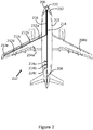
- Figure 2 shows an aircraft 200 installed with an optical communication system constructed in accordance with embodiments of the present invention.
- the aircraft 200 has a fuselage 202 and wings 204a and 204b.
- a cockpit 206 is located within a front end of the fuselage 202, and a tail 208 is located at the rear end of the fuselage.
- An avionic system (shown schematically as 210) is located within or near to the cockpit 206, and is configured to communicate with and control components in the aircraft 200.
- the aircraft 200 includes an optical communication system via which the avionic system 210 is able to communicate with nodes 212a-e and 214a-c at different locations on the aircraft 200 via optical fibres 216 and 218.
- the avionic system 210 is in communication with the nodes 212a-e via the optical fibre 216, and is in communication with the nodes 214a-c via the optical fibre 218.
- the nodes 212a-e are spaced along the length of the wing 204a, and each node may include one or more sensors to measure parameters such as, for example, temperature, pressure or strain at a leading edge of the wing.
- the nodes 214a-c are, in this example, located near to the rear end of the fuselage 202, and may each include one or more sensors configured to measure various parameters relating to the aircraft including, for example, air temperature, fuel temperature, fuel level, pressure, rotary position, linear position, landing gear load values, and landing gear strain.
- One or more of the nodes 212a-e and 214a-c could include individual sensors, or be used as communication nodes for transmitting data, as will be discussed below.
- the exemplary communication system shown in Figure 2 is configured to communicate data streams via the optical fibres 212, 214 by modulating the data streams onto carrier waves, as will be explained below.
- Modulation is the encoding of a signal, for example, a pattern, data, data stream or information to a media, for example radiation, in such a way that the encoded signal may be extracted or retrieved at another point in the media.
- a source of radiation such as light source 220 is, in this example, located near to the avionic system 210 in the aircraft 200.
- the light source 220 is a broadband light source which supplies broadband light to the nodes 212a-e, 214a-c via both of the optical fibres 212 and 214.
- the source of radiation 220 might include a different type of light source, such as a swept wavelength laser source but, generally, the communication system requires a radiation source capable of generating radiation at multiple wavelengths. It will also be appreciated that while, in this example, the light source 220 is located near to the front of the aircraft 200 with, near to or forming part of the avionic system 210, the light source may alternatively be located elsewhere on the aircraft.
- a single light source 220 may be provided to generate light for all of the optical fibres within the communication system.
- two or more light sources may be provided, and located together on the aircraft 200 or separately, at different locations on the aircraft.
- the communication system described herein is such that the light source 220, or light sources, can be located at a location remote from the nodes 212, 214. Therefore, the light source 220 can be located, for example, in a protected area of the aircraft, such as an avionics bay.
- a single cooling system may be used to cool multiple electrical components, rather than installing a cooling system for each electrical component.
- Each node 212, 214 in the communication system may be configured to function as a primitive passive sensor (arranged to measure, for example, temperature or pressure), as a receiver, as a transmitter, or as a sensor and/or a receiver and/or a transmitter.
- a primitive passive sensor arranged to measure, for example, temperature or pressure
- the transmit and receive functionality possible within the nodes will now be discussed with reference to Figures 3 to 9 which show, schematically, nodes of a communication system constructed in accordance with various embodiments of the invention.
- Figures 3 and 4 show arrangements in which nodes can function as receivers.
- Figure 3 shows a portion of an optical fibre 302 having a core 304 and cladding 306.
- a light source 308 is located at an end of the optical fibre 302, and is configured to generate broadband (white) light for transmission along the optical fibre.
- the light source 308 may be the same as the light source 220 shown in Figure 2 .
- the broadband light emitted by the light source 308 is divided into multiple wavebands using known wavelength division multiplexing (WDM) techniques.
- WDM wavelength division multiplexing
- a coarse-WDM technique may be employed to divide the broadband light into around sixteen to twenty wavebands, or channels.
- a fine-WDM technique may be employed to divide the broadband light into around thirty wavebands, or channels.
- different WDM techniques may be used to divide the light into a different number of wavebands or channels. It will be appreciated that, by using different WDM techniques, the broadband light from the light source 308 may be divided into more or fewer wavebands, as required. For clarity, the light emitted by the light source 308 in this embodiment has been divided into four wavebands. The light within each individual waveband may act as a carrier wave via which a data signal may be transmitted.
- a data signal to be transmitted along the optical fibre 302 is modulated onto a carrier wave using techniques that will be well known to those skilled in the art.
- a resulting modulated data stream can then be transmitted along the optical fibre 302.
- data streams are transmitted along the optical fibre 302 in the two wavebands labelled ⁇ 1 and ⁇ 2, and the nodes shown in Figures 3 and 4 are configured to function as receivers.
- a node 300 is shown in which an optical fibre grating is formed.
- the grating is a tilted fibre Bragg grating (FBG) 310, which is formed within the core 304 of the optical fibre 302.
- FBGs can be created in optical fibres using techniques that will be known to those skilled in the art, such as laser etching or inscribing.
- FBGs are configured to reflect radiation at a particular wavelength (or in a particular waveband) and to transmit radiation at all other wavelengths. Therefore, when white light travels along an optical fibre in one direction and reaches an FBG, a component of that white light is reflected back along the optical fibre in the opposite direction.
- the tilted FBG 310 reflects a component of the light (in this case, the light in the waveband ⁇ 2) out of the core 304 and through the cladding 306 of the optical fibre 302.
- a receiver 312 adjacent to, near to, or around the optical fibre 302 receives the reflected light, and can be used to recover the data from the data stream.
- the receiver 312 may be a photodetector, such as a photodiode, used to detect a signal transmitted, for example, from the avionics bay or cockpit of an aircraft.
- the transmitted signal may, for example, be an instruction to a particular component, such as to turn a component on or off. Alternatively, the transmitted signal may be used, for example, to activate an in-line switch.
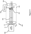
- Figure 4 shows a node 400 constructed according to an alternative embodiment, in which a long-period FBG 402 is formed within the core 304 of the optical fibre 302.
- the long-period FBG 402 affects only radiation having a wavelength within a particular waveband (in this case, the component of light in the waveband ⁇ 1), and transmits radiation at all other wavelengths.
- Some modes from the core 304 of the optical fiber 302 (the “core modes") couple with modes from the cladding 306 (the “cladding modes”).
- the component of light in the waveband ⁇ 1 and, therefore, the data stream transmitted in this waveband is coupled outside the core 304 and, therefore, travels into the cladding 306 of the optical fibre 302.
- a receiver 404 adjacent to, near to, or around the optical fibre 302 receives the reflected light, and can be used to recover the data from the data stream.
- the receiver 404 may be a photodetector, such as a photodiode or phototransistor, used to detect a signal transmitted, for example, from the avionics bay or cockpit of an aircraft.
- a coating may be applied to at least a portion of the optical fibre.
- the optical fibre 302 may be treated in some other way, or part of the cladding 306 may be removed.
- the arrangements shown in Figures 3 and 4 demonstrate how the use of FBGs allows nodes of an optical communication system to be used as receivers.
- the present invention also provides a mechanism by which a node can function as a transmitter, such that data can be transmitted from the node without the use of a laser source.
- the wavelength at which an FBG reflects radiation is determined by the structure of the grating or, more specifically, by the spacing or period of the grating.
- Changing the structure of an FBG for example by increasing or decreasing the grating spacing, changes the wavelength at which the FBG reflects radiation.
- the structure of an FBG can be changed or manipulated in a number of ways. For example, changing the temperature of the FBG can cause the grating spacing to change, with the result that radiation of a different wavelength will be reflected by the FBG.
- Another way of changing the structure of an FBG is to apply a force or strain to the FBG, for example by using a mechanical device to deform the grating through application of a tensile or a compressive force. In this way, the grating spacing is changed, resulting in a change in the wavelength at which the grating reflects radiation.
- FIG. 5A The effect of changing the grating spacing in an FBG on the wavelength at which radiation is reflected by the FBG is shown schematically in Figures 5A and 5B .
- an FBG 502 is in an unstrained form and, in this form, the FBG reflects radiation having a wavelength ⁇ a .
- Figure 5B shows the FBG 502 under strain. In this form, the FBG 502 reflects radiation having a wavelength ⁇ b , different to ⁇ a .
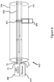
- FIG 6 shows an embodiment of the invention in which a node 600 can be used to transmit a signal.
- an FBG 602 is formed within the core 304 of the optical fibre 302.
- the FBG 602 is configured to reflect radiation having a wavelength within in the waveband ⁇ 3, and transmit all other radiation, including the radiation having wavelengths falling within the wavebands ⁇ 1, ⁇ 2 and ⁇ 4.
- a receiver 604 is located adjacent to or near to the light source 308, at the end of the optical fibre 302.
- the light source 308 in this embodiment is configured to generate broadband light (e.g. white light).
- broadband light e.g. white light
- Light having wavelengths falling within the wavebands used to transmit data streams to nodes functioning as receivers may be modulated with data.
- the light having a wavelength falling within the waveband ⁇ 3 is not modulated with data. Instead, the white light is transmitted along the optical fibre 302 to the FBG 602 where the component of the white light within the waveband ⁇ 3 is reflected.
- a mechanism or instrument 606 for manipulating, modifying or modulating the structure of the FBG 602 is coupled to the FBG.
- the instrument 606 may be any means suitable for controllably modifying or modulating the grating spacing of the FBG 602 including, but not limited to, a mechanical device, an electrical device, a current-inducing coil, a motor, such as a linear solenoid motor, or a magnetic field source, such as a coil, a radio frequency (RF) transmitter or a microwave transmitter, for generating a magnetic field to interact with a magneto-restrictive coating applied to a portion of the optical fibre containing the FBG.
- RF radio frequency
- An example of a suitable instrument 606 is discussed below with reference to Figure 7 .
- the instrument 606, and its effect on the FBG 602 may be accurately controlled and, accordingly, it is possible to accurately control the wavelength of radiation that is reflected by the FBG, back along the optical fibre 302, to the receiver 604.
- a signal having a particular wavelength can be transmitted by the node 600 to the receiver 604.
- the receiver 604, or a computer or processor associated with the receiver may be programmed with threshold values of wavelengths or discrete bands of wavelengths so that, if a signal is received from the node 600 above a particular threshold value, or falling within a particular wavelength band, it can be interpreted accordingly.
- a received signal having a wavelength falling above a threshold value may be interpreted as a "1" or "ON” response, indicating that a particular component associated with that node is in an "ON" or active state.
- a received signal having a wavelength falling below the threshold value may be interpreted as a "0" or “OFF” response, indicating that a particular component associated with that node is in an "OFF” or inactive state.
- one or more instruments may be used to varying parameters of the grating, or to affect the grating in different ways.
- the instrument is configured to controllably apply pressure to the FBG, thereby modulating the structure of the grating.
- the instrument is configured to controllably apply a vibration to the FBG to modulate the grating's structure.
- the instrument is configured to controllably vary the temperature of the FBG, and/or of the optical fibre which houses the FBG. Varying the temperature of the FBG can change the structure of the grating.
- Figure 7 shows an embodiment of the invention in which the instrument 606 is a mechanical instrument capable of applying a strain to the FBG 602.
- the instrument 606 includes a first end 702 mechanically coupled to the optical fibre at one end of the FBG 602 and a second end 704 mechanically coupled to the optical fibre at the other end of the FBG.
- the instrument 606 includes a coil 706 connected to a data source, for example a current source 708.
- the arrangement is analogous to a speaker coil arrangement.
- a magneto-restrictive coating is applied to the FBG, or to the portion of the optical fibre that houses the FBG. Magneto-restrictive materials change their shape or dimensions when they are subject to a magnetic field.
- the instrument includes means for generating a magnetic field, such as a radio frequency (RF) transmitter or a microwave transmitter.
- RF radio frequency
- a controllable magnetic field is generated and, when the FBG is positioned in the magnetic field, the magneto-restrictive coating changes its shape, causing the structure of the FBG to be modified.
- FIG 8 shows an embodiment of the invention in which a light source 308 is located at one end of the optical fibre 302, along with a receiver 800.
- FBGs 802 and 804 are similar to the FBG 602 described above, in that their structures can be controllably manipulated by instruments 806 and 808 respectively.
- the FBG 802 is configured to reflect light having a wavelength falling within the waveband ⁇ 4
- FBG 804 is configured to reflect light having a wavelength falling within the waveband ⁇ 3.
- Tilted FBG 810 is similar to the tilted FBG 310 described above, and is configured to reflect light having a wavelength falling within the waveband ⁇ 2 towards a receiver 812.
- the long-period FBG 814 is similar to the long-period FBG 402 described above, and is configured to reflect light having a wavelength falling within the waveband ⁇ 1 towards a receiver 816.
- the FBG 802 and the tilted FBG 810 are located near to one another on a first node, and the FBG 804 and the long-period FBG 814 are located near to one another on a second node.
- a signal may be received by the receiver 812 and, in response to the received signal, a response signal may be transmitted to the receiver 800 from the FBG 802, using the instrument 806 to control its grating spacing.
- a signal may be received by the receiver 816 and, in response to the received signal, a response signal may be transmitted to the receiver 800 from the FBG 804, using the instrument 808 to control its grating spacing.
- the signal received at the receivers 812, 816 may be in response to the signal transmitted to the receiver 800 from the FBGs 802, 804 resulting from the modulation by the instruments 806, 808.
- FIGS. 9A, 9B and 9C show examples of possible responses from a node functioning as a transmitter, as described above.
- Figure 9A shows a first set of responses.
- a data signal generated by a binary node can represent an "ON” state or an "OFF” state.
- the receiver interprets a response 902 (which has a wavelength falling within a waveband ⁇ a ) as meaning "ON”, and interprets a response 904 (which has a wavelength falling within a waveband ⁇ b ) as meaning "OFF”.
- a response having any other wavelength might be interpreted as an error message, suggesting that something unexpected has happened at the node, such as a short circuit or a power surge.
- Figure 9B shows a second set of responses.
- the receiver scans for a response 908 falling within a single waveband ⁇ c .
- a response within the waveband ⁇ c would be interpreted as meaning "ON”, while a response such as response 906, which has a wavelength falling outside of the waveband ⁇ c , or a lack of a response at all, would be interpreted as meaning "OFF”.
- Figure 9C shows a third set of responses.
- a wider waveband is scanned and the actual response wavelength is determined in an analogue way between a minimum ⁇ d_min and maximum point ⁇ d_max .
- Responses 910 and 912 therefore represent analogue points on a continuous scale and may represent non-binary data such as a current measurement or samples in an audio signal.
- Such an audio signal may be the result of analogue passive components and/or energy harvesting techniques, allowing zero-power data communication to be made from the node.
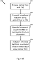
- the invention also provides a method for communicating a signal via an optical fibre.
- Figure 10 is a flow diagram detailing the steps of the method 1000.
- an optical fibre is provided.
- the optical fibre includes an optical fibre grating.
- the grating is fibre Bragg grating (FBG) which is formed within the core of the optical fibre.
- FBG fibre Bragg grating
- a light source may be used to transmit broadband radiation along the optical fibre towards the FBG.
- an instrument that is coupled to the FBG is operated to controllably manipulate the structure of the FBG.
- radiation having a particular wavelength is reflected by the FBG, modulated by the instrument, and transmitted back along the optical fibre to a receiver.
- FBGs fibre Bragg gratings
Landscapes
- Physics & Mathematics (AREA)
- General Physics & Mathematics (AREA)
- Optics & Photonics (AREA)
- Nonlinear Science (AREA)
- Engineering & Computer Science (AREA)
- Computer Networks & Wireless Communication (AREA)
- Signal Processing (AREA)
- Electromagnetism (AREA)
- Optical Communication System (AREA)
Abstract
Description
- The present invention relates to communication and, more particularly, to an apparatus and method for communicating a signal via an optical fibre.
- Optical communication is a known technique by which data signals can be transmitted from a transmitter to a receiver using optical fibre. Typically, an optical transmitter converts an electrical signal into an optical signal, which forms a carrier wave. The carrier wave is modulated with a modulation signal (i.e. the data), and is then transmitted along the optical fibre to a receiver, which converts the optical signal back into an electrical signal and recovers the transmitted data.
- A single optical fibre can be used to transmit a large number of individual data streams, or channels, by transmitting radiation having a range of wavelengths (for example broadband radiation) through the optical fibre, and using a wavelength-division multiplexing (WDM) system to divide the radiation into discrete wavelengths or wavebands. A separate data stream can then be transmitted within each waveband.
- In order to recover the data transmitted in one data stream (i.e. in one waveband) within an optical fibre, it is necessary to route the data stream out of the optical fibre to a receiver. One known method for achieving this is through the use of an optical add-drop multiplexer (OADM), which routes one data stream out of the optical fibre, and routes another data stream into the optical fibre to make use of the empty waveband.
- An example of a
system 100 using a known optical add-drop multiplexer (OADM) 102 is shown schematically inFigure 1 . In theexemplary system 100, wavelength-division multiplexing is used to divide the radiation passing through anoptical fibre 104 into four discrete wavebands λ1, λ2, λ3 and λ4. Each waveband is capable of carrying a single data stream. - An optical fibre grating which, in this case is a fibre Bragg grating (FBG) 106, is formed within the
optical fibre 104. A fibre Bragg grating is an optical instrument which can be configured to reflect radiation at a particular wavelength (or in a particular waveband) and to transmit radiation at all other wavelengths. In the example shown inFigure 1 , the FBG 106 is configured to reflect radiation having wavelength within the waveband λ4, and transmit all other radiation, including the radiation having wavelengths within the wavebands λ1, λ2 and λ3. Therefore, while the data streams being transmitted in the wavebands λ1, λ2 and λ3 are able to travel along theoptical fibre 104 through theFBG 106, the data stream being transmitted in the waveband λ4 is reflected by the FBG back along the optical fibre in the direction from which it came. - The reflected radiation is fed into a first
optical circulator 108 which routes the reflected radiation out of theoptical fibre 104 to a receiver (not shown). The radiation that is routed out of theoptical fibre 104 by the OADM 102 is known as a "dropped" path. Since the data stream that was in the waveband λ4 has been removed from theoptical fibre 104, it is possible to add a new data stream to be transmitted in the waveband λ4 (i.e. an "added path"). This is achieved by modulating a carrier wave in the waveband λ4, and feeding it into theoptical fibre 104 after the FBG 106. In order to provide a carrier wave at the desired wavelength (i.e. in waveband λ4), theknown system 100 uses a laser (not shown). Radiation at the desired wavelength λ4 from the laser is fed into theoptical fibre 104, and a secondoptical circulator 110 routes the radiation along the optical fibre in the original direction of transmission. - A system such as the
exemplary system 100 might be positioned at each node in an optical fibre communication network. Such a communication network might be installed in an aircraft, where optical fibre networks are preferred to electric cable networks due to their resilience to electromagnetic interference compared to electrical cables, and due to the fact that optical fibres are generally less heavy than shielded electrical cables. However, for each node in the network to be able to transmit data, each node would require a laser source which itself is very power intensive, and may require an active cooling system. Installing a laser source at each node in a network on an aircraft can negate the benefits provided by the lighter cables. - A first aspect of the invention provides a communication apparatus, comprising: an optical fibre along which radiation can be transmitted; an optical fibre grating formed within the optical fibre, the optical fibre grating having a structure, and being configured to reflect radiation at a particular wavelength; and an instrument coupled to the grating and configured to controllably modify the structure of the grating, thereby changing the wavelength at which the grating reflects radiation.
- An aspect of the invention provides a communication apparatus, comprising: an optical fibre along which radiation can be transmitted; an optical fibre grating formed within the optical fibre, the optical fibre grating having a structure, and being configured to reflect radiation at a particular wavelength; and an instrument coupled to the grating and configured to receive a data signal and controllably modify the structure of the grating in response to the received data signal, thereby changing the wavelength at which the grating reflects radiation, to encode a signal in the radiation at the particular wavelength in response to the received data signal.
- The communication apparatus may further comprise a receiver configured to detect the radiation at the particular wavelength reflected by the optical fibre grating and interpret the encoded signal in the radiation at the particular wavelength reflected by the optical fibre grating.
- The communication apparatus may further comprise a receiver configured to detect the radiation at the particular wavelength transmitted through the optical fibre grating and interpret the encoded signal in the radiation at the particular wavelength transmitted through the optical fibre grating.
- The instrument may be configured to controllably modulate the structure of the grating to modulate the wavelength at which the grating reflects radiation so that the encoded signal is generated.
- The apparatus may form a node in an optical fibre network.
- The node may further include at least one of: a tilted optical fibre grating and a long-period optical fibre grating, configured to direct radiation out of the optical fibre.
- The node may further comprise a receiving module configured to detect radiation directed out of the optical fibre and interpret a communication signal in the radiation directed out of the optical fibre.
- The data signal received by the instrument may be the communication signal.
- The communication signal may be at a different wavelength and/or wavelength band from the encoded signal.
- The instrument may comprise a mechanical instrument configured to controllably apply a strain to the optical fibre grating. The optical fibre housing the optical fibre grating may include a magneto-restrictive coating, and the instrument may be configured to generate a controllable magnetic field capable of interacting with the coating, thereby modifying the structure of the grating.
- The instrument may comprise a coil coupled to the optical fibre grating, the coil configured to induce a strain in the grating in response to a current applied to the coil.
- The instrument may comprise an instrument configured to controllably apply a pressure or a vibration to the optical fibre grating, or to controllably vary the temperature of the optical fibre grating and/or the optical fibre housing the grating.
- Controllably modifying the structure of the grating may comprise controllably modifying the grating spacing or grating period of the optical fibre grating.
- The optical fibre grating may comprise a fibre Bragg grating.
- The apparatus may be installed in a vehicle, such as an aircraft.
- A further aspect of the invention provides a method of communicating a signal via an optical fibre, the method comprising: providing an optical fibre having a first optical fibre grating formed therein, the first optical fibre grating having a structure, and being configured to reflect radiation at a particular wavelength; and operating an instrument coupled to the grating to manipulate the structure of the grating, to thereby change the wavelength at which the first grating reflects radiation. The optical fibre grating may comprise a fibre Bragg grating.
- An aspect of the invention provides a method of communicating a signal via an optical fibre, the method comprising: providing an optical fibre having a first optical fibre grating formed therein, the first optical fibre grating having a structure, and being configured to reflect radiation at a particular wavelength; receiving a data signal, operating an instrument coupled to the grating to manipulate the structure of the grating in response to the received data signal, to thereby change the wavelength at which the first grating reflects radiation, to encode a signal in the radiation at the particular wavelength in response to the received data signal.
- The method may further comprise: operating a light source to transmit radiation along the optical fibre towards the first optical fibre grating; and receiving, at a receiver, radiation at the particular wavelength reflected by the first optical fibre grating.
- The method may further comprise: interpreting a signal received at the receiver from the first optical fibre grating, based on the wavelength of the radiation reflected by the grating.
- The method may further comprise: operating the instrument to controllably modulate the structure of the grating to modulate the wavelength at which the grating reflects radiation so that the encoded signal is generated.
- The method may further comprise: operating a light source to transmit radiation along the optical fibre towards the first optical fibre grating; and
receiving, at a receiver, radiation at the particular wavelength transmitted through the first optical fibre grating. - The method may further comprise: interpreting a signal received at the receiver from the first optical fibre grating, based on the wavelength of the radiation transmitted through the first optical fibre grating.
- The method may further comprise: receiving, at a second optical fibre grating, a data signal transmitted via the optical fibre; wherein the manipulation of the structure of the first optical fibre grating is done in response to the receipt of said data signal.
- A further aspect of the invention provides a communication system, comprising: an apparatus as described above; a light source for generating radiation to be transmitted along the optical fibre; and a receiver configured to receive radiation reflected by the optical fibre grating. The system may include more than one apparatus and/or more than one light source and/or more than one receiver.
- The light source and the receiver may be located at a first end of the optical fibre. The light source may be a swept-wavelength laser, or may be configured to generate broadband radiation.
- There are numerous advantages of forming a communication system using optical fibre rather than shielded electrical cable. Optical fibre is generally smaller and lighter than shielded electrical cable. Nodes in an optical communication network can, therefore, also be smaller and lighter. Furthermore, a node which is able to transmit a signal without the use of a laser source to generate radiation at a particular wavelength can be produced for a lower cost than a node which includes a laser source. Such a node is also lighter in weight, and less power-intensive than a node requiring a laser source. If a node in an optical network fails, the other nodes in the network can continue to operate, since the signals transmitted to and from each node are carried in different discrete wavebands. Thus, embodiments of the present invention provide advantages over the known art.
- Other features of the invention will be become apparent from the following description.
- Embodiments of the invention will now be described with reference to the accompanying drawings, in which:
-
Figure 1 is an example of an optical system incorporating a known optical add-drop multiplexer; -
Figure 2 is a schematic diagram of an optical communication system installed in an aircraft; -
Figure 3 is a schematic diagram of a node in an optical communication system configured to function as a receiver in accordance with an embodiment of the invention; -
Figure 4 is a schematic diagram of a node in an optical communication system configured to function as a receiver in accordance with another embodiment of the invention; -
Figures 5A and 5B are graphs showing the effect of applying a strain to a fibre Bragg grating; -
Figure 6 is a schematic diagram of a node in an optical communication system configured to function as a transmitter in accordance with an embodiment of the invention; -
Figure 7 is a schematic diagram of an instrument used to manipulate a grating; -
Figure 8 is a schematic diagram of an optical fibre including two nodes forming part of an optical communication system; -
Figures 9A, 9B and 9C show example responses of a node functioning as a transmitter; and -
Figure 10 is a flow diagram showing the steps of a method for transmitting data in accordance with the present invention. - Some embodiments of the present invention are described in the context of optical communication systems on aircraft. It will be appreciated by those skilled in the art, however, that the described communication apparatus, methods and systems may be installed in systems other than aircraft. For example, the described systems may be used in buildings or other vehicles, such as motor vehicles.
- Referring to the drawings,
Figure 2 shows an aircraft 200 installed with an optical communication system constructed in accordance with embodiments of the present invention. The aircraft 200 has afuselage 202 andwings cockpit 206 is located within a front end of thefuselage 202, and atail 208 is located at the rear end of the fuselage. An avionic system (shown schematically as 210) is located within or near to thecockpit 206, and is configured to communicate with and control components in the aircraft 200. - The aircraft 200 includes an optical communication system via which the
avionic system 210 is able to communicate withnodes 212a-e and 214a-c at different locations on the aircraft 200 viaoptical fibres Figure 2 , theavionic system 210 is in communication with thenodes 212a-e via theoptical fibre 216, and is in communication with thenodes 214a-c via theoptical fibre 218. In this example, thenodes 212a-e are spaced along the length of thewing 204a, and each node may include one or more sensors to measure parameters such as, for example, temperature, pressure or strain at a leading edge of the wing. Similarly, thenodes 214a-c are, in this example, located near to the rear end of thefuselage 202, and may each include one or more sensors configured to measure various parameters relating to the aircraft including, for example, air temperature, fuel temperature, fuel level, pressure, rotary position, linear position, landing gear load values, and landing gear strain. One or more of thenodes 212a-e and 214a-c could include individual sensors, or be used as communication nodes for transmitting data, as will be discussed below. - It will be appreciated that, while the exemplary communication system shown in
Figure 2 includes twooptical fibres nodes 212a-e and 214a-c, a typical communication system installed in an aircraft is likely to include a greater number of nodes and a greater number of optical fibres. However, it will also be appreciated that such systems may include fewer optical fibres and fewer nodes. - The exemplary communication system shown in
Figure 2 is configured to communicate data streams via the optical fibres 212, 214 by modulating the data streams onto carrier waves, as will be explained below. - Modulation is the encoding of a signal, for example, a pattern, data, data stream or information to a media, for example radiation, in such a way that the encoded signal may be extracted or retrieved at another point in the media.
- A source of radiation, such as
light source 220 is, in this example, located near to theavionic system 210 in the aircraft 200. In some embodiments, thelight source 220 is a broadband light source which supplies broadband light to thenodes 212a-e, 214a-c via both of the optical fibres 212 and 214. In some embodiments, the source ofradiation 220 might include a different type of light source, such as a swept wavelength laser source but, generally, the communication system requires a radiation source capable of generating radiation at multiple wavelengths. It will also be appreciated that while, in this example, thelight source 220 is located near to the front of the aircraft 200 with, near to or forming part of theavionic system 210, the light source may alternatively be located elsewhere on the aircraft. - A single
light source 220 may be provided to generate light for all of the optical fibres within the communication system. Alternatively, two or more light sources may be provided, and located together on the aircraft 200 or separately, at different locations on the aircraft. Advantageously, the communication system described herein is such that thelight source 220, or light sources, can be located at a location remote from the nodes 212, 214. Therefore, thelight source 220 can be located, for example, in a protected area of the aircraft, such as an avionics bay. By locating thelight source 220 in an area of the aircraft 200 where other electronics systems are located, a single cooling system may be used to cool multiple electrical components, rather than installing a cooling system for each electrical component. - Each node 212, 214 in the communication system may be configured to function as a primitive passive sensor (arranged to measure, for example, temperature or pressure), as a receiver, as a transmitter, or as a sensor and/or a receiver and/or a transmitter. The transmit and receive functionality possible within the nodes will now be discussed with reference to
Figures 3 to 9 which show, schematically, nodes of a communication system constructed in accordance with various embodiments of the invention. -
Figures 3 and4 show arrangements in which nodes can function as receivers.Figure 3 shows a portion of anoptical fibre 302 having acore 304 andcladding 306. Alight source 308 is located at an end of theoptical fibre 302, and is configured to generate broadband (white) light for transmission along the optical fibre. Thelight source 308 may be the same as thelight source 220 shown inFigure 2 . The broadband light emitted by thelight source 308 is divided into multiple wavebands using known wavelength division multiplexing (WDM) techniques. In some embodiments, a coarse-WDM technique may be employed to divide the broadband light into around sixteen to twenty wavebands, or channels. In other embodiments, a fine-WDM technique may be employed to divide the broadband light into around thirty wavebands, or channels. Alternatively, different WDM techniques may be used to divide the light into a different number of wavebands or channels. It will be appreciated that, by using different WDM techniques, the broadband light from thelight source 308 may be divided into more or fewer wavebands, as required. For clarity, the light emitted by thelight source 308 in this embodiment has been divided into four wavebands. The light within each individual waveband may act as a carrier wave via which a data signal may be transmitted. - A data signal to be transmitted along the
optical fibre 302 is modulated onto a carrier wave using techniques that will be well known to those skilled in the art. A resulting modulated data stream can then be transmitted along theoptical fibre 302. In the embodiments discussed inFigures 3 and4 , data streams are transmitted along theoptical fibre 302 in the two wavebands labelled λ1 and λ2, and the nodes shown inFigures 3 and4 are configured to function as receivers. - In the embodiment shown in
Figure 3 , anode 300 is shown in which an optical fibre grating is formed. In this embodiment, the grating is a tilted fibre Bragg grating (FBG) 310, which is formed within thecore 304 of theoptical fibre 302. FBGs can be created in optical fibres using techniques that will be known to those skilled in the art, such as laser etching or inscribing. Generally, FBGs are configured to reflect radiation at a particular wavelength (or in a particular waveband) and to transmit radiation at all other wavelengths. Therefore, when white light travels along an optical fibre in one direction and reaches an FBG, a component of that white light is reflected back along the optical fibre in the opposite direction. The tiltedFBG 310 reflects a component of the light (in this case, the light in the waveband λ2) out of thecore 304 and through thecladding 306 of theoptical fibre 302. Areceiver 312 adjacent to, near to, or around theoptical fibre 302 receives the reflected light, and can be used to recover the data from the data stream. Thereceiver 312 may be a photodetector, such as a photodiode, used to detect a signal transmitted, for example, from the avionics bay or cockpit of an aircraft. The transmitted signal may, for example, be an instruction to a particular component, such as to turn a component on or off. Alternatively, the transmitted signal may be used, for example, to activate an in-line switch. -
Figure 4 shows anode 400 constructed according to an alternative embodiment, in which a long-period FBG 402 is formed within thecore 304 of theoptical fibre 302. The long-period FBG 402 affects only radiation having a wavelength within a particular waveband (in this case, the component of light in the waveband λ1), and transmits radiation at all other wavelengths. Some modes from thecore 304 of the optical fiber 302 (the "core modes") couple with modes from the cladding 306 (the "cladding modes"). As a result, the component of light in the waveband λ1 and, therefore, the data stream transmitted in this waveband, is coupled outside thecore 304 and, therefore, travels into thecladding 306 of theoptical fibre 302. Areceiver 404 adjacent to, near to, or around theoptical fibre 302 receives the reflected light, and can be used to recover the data from the data stream. As with thereceiver 312, thereceiver 404 may be a photodetector, such as a photodiode or phototransistor, used to detect a signal transmitted, for example, from the avionics bay or cockpit of an aircraft. To aid transmission of radiation through thecladding 306 of theoptical fibre 302, a coating may be applied to at least a portion of the optical fibre. Alternatively, theoptical fibre 302 may be treated in some other way, or part of thecladding 306 may be removed. - The arrangements shown in
Figures 3 and4 demonstrate how the use of FBGs allows nodes of an optical communication system to be used as receivers. The present invention also provides a mechanism by which a node can function as a transmitter, such that data can be transmitted from the node without the use of a laser source. - The wavelength at which an FBG reflects radiation is determined by the structure of the grating or, more specifically, by the spacing or period of the grating. Changing the structure of an FBG, for example by increasing or decreasing the grating spacing, changes the wavelength at which the FBG reflects radiation. The structure of an FBG can be changed or manipulated in a number of ways. For example, changing the temperature of the FBG can cause the grating spacing to change, with the result that radiation of a different wavelength will be reflected by the FBG. Another way of changing the structure of an FBG is to apply a force or strain to the FBG, for example by using a mechanical device to deform the grating through application of a tensile or a compressive force. In this way, the grating spacing is changed, resulting in a change in the wavelength at which the grating reflects radiation.
- The effect of changing the grating spacing in an FBG on the wavelength at which radiation is reflected by the FBG is shown schematically in
Figures 5A and 5B . InFigure 5A , anFBG 502 is in an unstrained form and, in this form, the FBG reflects radiation having a wavelength λa.Figure 5B shows theFBG 502 under strain. In this form, theFBG 502 reflects radiation having a wavelength λb, different to λa. Thus, by controlling the amount of strain applied to an FBG, it is possible to accurately control the wavelength at which radiation is reflected by the FBG. -
Figure 6 shows an embodiment of the invention in which anode 600 can be used to transmit a signal. In the embodiment shown inFigure 6 , anFBG 602 is formed within thecore 304 of theoptical fibre 302. TheFBG 602 is configured to reflect radiation having a wavelength within in the waveband λ3, and transmit all other radiation, including the radiation having wavelengths falling within the wavebands λ1, λ2 and λ4. - A
receiver 604 is located adjacent to or near to thelight source 308, at the end of theoptical fibre 302. An advantage of this arrangement, as is discussed above, is that thelight source 308 and thereceiver 604 can be located near to each other, for example in the avionics bay of an aircraft, remote from the nodes. - As with the embodiments described above, the
light source 308 in this embodiment is configured to generate broadband light (e.g. white light). Light having wavelengths falling within the wavebands used to transmit data streams to nodes functioning as receivers may be modulated with data. However, the light having a wavelength falling within the waveband λ3 is not modulated with data. Instead, the white light is transmitted along theoptical fibre 302 to theFBG 602 where the component of the white light within the waveband λ3 is reflected. - A mechanism or
instrument 606 for manipulating, modifying or modulating the structure of theFBG 602 is coupled to the FBG. Theinstrument 606 may be any means suitable for controllably modifying or modulating the grating spacing of theFBG 602 including, but not limited to, a mechanical device, an electrical device, a current-inducing coil, a motor, such as a linear solenoid motor, or a magnetic field source, such as a coil, a radio frequency (RF) transmitter or a microwave transmitter, for generating a magnetic field to interact with a magneto-restrictive coating applied to a portion of the optical fibre containing the FBG. An example of asuitable instrument 606 is discussed below with reference toFigure 7 . In general, however, theinstrument 606, and its effect on theFBG 602, may be accurately controlled and, accordingly, it is possible to accurately control the wavelength of radiation that is reflected by the FBG, back along theoptical fibre 302, to thereceiver 604. - Using the arrangement shown in
Figure 6 , a signal having a particular wavelength can be transmitted by thenode 600 to thereceiver 604. Thereceiver 604, or a computer or processor associated with the receiver, may be programmed with threshold values of wavelengths or discrete bands of wavelengths so that, if a signal is received from thenode 600 above a particular threshold value, or falling within a particular wavelength band, it can be interpreted accordingly. For example, a received signal having a wavelength falling above a threshold value may be interpreted as a "1" or "ON" response, indicating that a particular component associated with that node is in an "ON" or active state. A received signal having a wavelength falling below the threshold value may be interpreted as a "0" or "OFF" response, indicating that a particular component associated with that node is in an "OFF" or inactive state. - According to various embodiments of the invention, one or more instruments may be used to varying parameters of the grating, or to affect the grating in different ways. For example, in one embodiment, the instrument is configured to controllably apply pressure to the FBG, thereby modulating the structure of the grating. In another embodiment, the instrument is configured to controllably apply a vibration to the FBG to modulate the grating's structure. In yet another embodiment, the instrument is configured to controllably vary the temperature of the FBG, and/or of the optical fibre which houses the FBG. Varying the temperature of the FBG can change the structure of the grating.
-
Figure 7 shows an embodiment of the invention in which theinstrument 606 is a mechanical instrument capable of applying a strain to theFBG 602. In this embodiment, theinstrument 606 includes afirst end 702 mechanically coupled to the optical fibre at one end of theFBG 602 and asecond end 704 mechanically coupled to the optical fibre at the other end of the FBG. Theinstrument 606 includes acoil 706 connected to a data source, for example acurrent source 708. The arrangement is analogous to a speaker coil arrangement. When a current is applied to the coil, a motive force is induced in the instrument, causing the first and second ends 702, 704 of the instrument to move relative to one another. This movement causes a strain to be applied to theFBG 602, thereby modifying the grating spacing. - In another embodiment (not shown), a magneto-restrictive coating is applied to the FBG, or to the portion of the optical fibre that houses the FBG. Magneto-restrictive materials change their shape or dimensions when they are subject to a magnetic field. The instrument includes means for generating a magnetic field, such as a radio frequency (RF) transmitter or a microwave transmitter. A controllable magnetic field is generated and, when the FBG is positioned in the magnetic field, the magneto-restrictive coating changes its shape, causing the structure of the FBG to be modified. By accurately controlling the strength of the magnetic field (for example by controlling a supply voltage or current), it is possible to accurately control the strain induced on the FBG and, therefore, the change in the grating spacing of the FBG.
-
Figure 8 shows an embodiment of the invention in which alight source 308 is located at one end of theoptical fibre 302, along with areceiver 800. Four FBGs are formed within thecore 304 of theoptical fibre 302.FBGs FBG 602 described above, in that their structures can be controllably manipulated byinstruments FBG 802 is configured to reflect light having a wavelength falling within the waveband λ4, andFBG 804 is configured to reflect light having a wavelength falling within the waveband λ3.Tilted FBG 810 is similar to the tiltedFBG 310 described above, and is configured to reflect light having a wavelength falling within the waveband λ2 towards areceiver 812. The long-period FBG 814 is similar to the long-period FBG 402 described above, and is configured to reflect light having a wavelength falling within the waveband λ1 towards areceiver 816. In this embodiment, theFBG 802 and the tiltedFBG 810 are located near to one another on a first node, and theFBG 804 and the long-period FBG 814 are located near to one another on a second node. Thus, at the first node, a signal may be received by thereceiver 812 and, in response to the received signal, a response signal may be transmitted to thereceiver 800 from theFBG 802, using theinstrument 806 to control its grating spacing. Similarly, at the second node, a signal may be received by thereceiver 816 and, in response to the received signal, a response signal may be transmitted to thereceiver 800 from theFBG 804, using theinstrument 808 to control its grating spacing. Alternatively, the signal received at thereceivers receiver 800 from theFBGs instruments - By using the apparatus and system described above, it is possible to transmit both digital and analogue data from a node in an optical fibre, without the use of a laser source or electrically powered components.
Figures 9A, 9B and 9C show examples of possible responses from a node functioning as a transmitter, as described above. -
Figure 9A shows a first set of responses. In this example, a data signal generated by a binary node can represent an "ON" state or an "OFF" state. The receiver interprets a response 902 (which has a wavelength falling within a waveband λa) as meaning "ON", and interprets a response 904 (which has a wavelength falling within a waveband λb) as meaning "OFF". A response having any other wavelength might be interpreted as an error message, suggesting that something unexpected has happened at the node, such as a short circuit or a power surge. -
Figure 9B shows a second set of responses. In this example, the receiver scans for aresponse 908 falling within a single waveband λc. A response within the waveband λc would be interpreted as meaning "ON", while a response such asresponse 906, which has a wavelength falling outside of the waveband λc, or a lack of a response at all, would be interpreted as meaning "OFF". -
Figure 9C shows a third set of responses. In this example, a wider waveband is scanned and the actual response wavelength is determined in an analogue way between a minimum λd_min and maximum point λd_max.Responses - The invention also provides a method for communicating a signal via an optical fibre.
Figure 10 is a flow diagram detailing the steps of themethod 1000. - At
step 1002, an optical fibre is provided. The optical fibre includes an optical fibre grating. In this embodiment, the grating is fibre Bragg grating (FBG) which is formed within the core of the optical fibre. Atstep 1004, a light source may be used to transmit broadband radiation along the optical fibre towards the FBG. Atstep 1006, an instrument that is coupled to the FBG is operated to controllably manipulate the structure of the FBG. Atstep 1008, radiation having a particular wavelength is reflected by the FBG, modulated by the instrument, and transmitted back along the optical fibre to a receiver. - Those skilled in the art of optical communications will appreciate that the apparatus, methods and systems described herein may be used to communicate digital data signals or analogue data signals. It will also be appreciated that, while fibre Bragg gratings (FBGs) have been referred to in some specific embodiments, other types of optical fibre gratings known to those skilled in the art could be used.
- Although the invention has been described above with reference to one or more preferred embodiments, it will be appreciated that various changes or modifications may be made without departing from the scope of the invention as defined in the appended claims. Furthermore, embodiments of the invention may be combined with one another, and features from individual embodiments may be combined with features from other embodiments without departing from the scope of the invention.
Claims (15)
- A communication apparatus, comprising:an optical fibre along which radiation can be transmitted;an optical fibre grating formed within the optical fibre, the optical fibre grating having a structure, and being configured to reflect radiation at a particular wavelength; andan instrument coupled to the grating and configured to receive a data signal and controllably modify the structure of the grating in response to the received data signal, thereby changing the wavelength at which the grating reflects radiation, to encode a signal in the radiation at the particular wavelength in response to the received data signal.
- A communication apparatus according to claim 1, further comprising a receiver configured to detect the radiation at the particular wavelength reflected by the optical fibre grating and interpret the encoded signal in the radiation at the particular wavelength reflected by the optical fibre grating.
- A communication apparatus according to claim 1, further comprising a receiver configured to detect the radiation at the particular wavelength transmitted through the optical fibre grating and interpret the encoded signal in the radiation at the particular wavelength transmitted through the optical fibre grating.
- A communication apparatus according to any of claims 1, 2 or 3, wherein the instrument is configured to controllably modulate the structure of the grating to modulate the wavelength at which the grating reflects radiation so that the encoded signal is generated.
- A communication apparatus according to any of the preceding claims, wherein the apparatus forms a node in an optical fibre network.
- A communication apparatus according to claim 5, wherein the node further includes at least one of: a tilted optical fibre grating and a long-period optical fibre grating, configured to direct radiation out of the optical fibre and, optionally, wherein the node further comprises a receiving module configured to detect radiation directed out of the optical fibre and interpret a communication signal in the radiation directed out of the optical fibre.
- A communication apparatus according to claim 6, wherein the data signal received by the instrument is the communication signal and, optionally, wherein the communication signal is at a different wavelength and/or wavelength band from the encoded signal.
- A communication apparatus according to any of the preceding claims, wherein the optical fibre grating comprises a fibre Bragg grating.
- A communication apparatus according to any of the preceding claims, wherein the apparatus is installed in a vehicle and, optionally, wherein the vehicle is an aircraft.
- A method of communicating a signal via an optical fibre, the method comprising:providing an optical fibre having a first optical fibre grating formed therein, the first optical fibre grating having a structure, and being configured to reflect radiation at a particular wavelength;receiving a data signal, andoperating an instrument coupled to the grating to manipulate the structure of the grating in response to the received data signal, to thereby change the wavelength at which the first grating reflects radiation, to encode a signal in the radiation at the particular wavelength in response to the received data signal.
- A method according to claim 10, further comprising:operating a light source to transmit radiation along the optical fibre towards the first optical fibre grating; andreceiving, at a receiver, radiation at the particular wavelength reflected by or transmitted through the first optical fibre grating.
- A method according to claim 11, further comprising:interpreting a signal received at the receiver from the first optical fibre grating, based on the wavelength of the radiation reflected by the grating.
- A method according to any of claims 10, 11 or 12, further comprising:operating the instrument to controllably modulate the structure of the grating to modulate the wavelength at which the grating reflects radiation so that the encoded signal is generated.
- A method according to any of claims 10 to 13, further comprising:receiving, at a second optical fibre grating, a data signal transmitted via the optical fibre;wherein the manipulation of the structure of the first optical fibre grating is done in response to the receipt of said data signal.
- A method according to any of claims 10 to 14, further comprising:receiving, at a second optical fibre grating, a data signal transmitted via the optical fibre;wherein the data signal is received at the second optical fibre grating in response to the manipulation of the structure of the first optical fibre grating.
Applications Claiming Priority (1)
| Application Number | Priority Date | Filing Date | Title |
|---|---|---|---|
| GB1519132.3A GB2543806A (en) | 2015-10-29 | 2015-10-29 | Communication apparatus |
Publications (2)
| Publication Number | Publication Date |
|---|---|
| EP3163338A1 true EP3163338A1 (en) | 2017-05-03 |
| EP3163338B1 EP3163338B1 (en) | 2025-04-02 |
Family
ID=55130395
Family Applications (1)
| Application Number | Title | Priority Date | Filing Date |
|---|---|---|---|
| EP16196266.7A Active EP3163338B1 (en) | 2015-10-29 | 2016-10-28 | Communication apparatus |
Country Status (4)
| Country | Link |
|---|---|
| US (1) | US9939665B2 (en) |
| EP (1) | EP3163338B1 (en) |
| CN (1) | CN106656332A (en) |
| GB (1) | GB2543806A (en) |
Cited By (1)
| Publication number | Priority date | Publication date | Assignee | Title |
|---|---|---|---|---|
| EP4560941A1 (en) | 2023-11-27 | 2025-05-28 | Airbus Defence and Space GmbH | Photonic transceiver module, periphery device, communication system and apparatus comprising same |
Families Citing this family (4)
| Publication number | Priority date | Publication date | Assignee | Title |
|---|---|---|---|---|
| GB2549500A (en) * | 2016-04-19 | 2017-10-25 | Airbus Operations Ltd | Node for an optical network |
| GB2556885A (en) | 2016-11-23 | 2018-06-13 | Airbus Operations Ltd | A fibre-optic communication system and an aircraft |
| GB2569340A (en) * | 2017-12-14 | 2019-06-19 | Airbus Operations Ltd | System installed on an aircraft |
| JP2022511424A (en) * | 2018-11-21 | 2022-01-31 | コーニング インコーポレイテッド | Optical system with multi-core optical fiber for direct core-to-core coupling |
Citations (4)
| Publication number | Priority date | Publication date | Assignee | Title |
|---|---|---|---|---|
| US5889901A (en) * | 1997-06-06 | 1999-03-30 | University Technology Corporation | Strain measuring apparatus/method having a sensor and a reference optical fiber grating |
| WO2001035138A1 (en) * | 1999-11-09 | 2001-05-17 | Optoplan As | Wavelength controlled fbg filter |
| WO2002016979A2 (en) * | 2000-08-24 | 2002-02-28 | Sabeus Photonics, Inc. | Fiberoptic bus, modulator, detector and emitter using cladding mode coupling |
| WO2015088967A1 (en) * | 2013-12-11 | 2015-06-18 | Moog Inc. | Fiber optic sensing and control system |
Family Cites Families (7)
| Publication number | Priority date | Publication date | Assignee | Title |
|---|---|---|---|---|
| FR2734676B1 (en) * | 1995-05-23 | 1997-08-08 | Labeyrie Antoine | LASER EMISSION OR RECEPTION METHOD AND DEVICES FOR OPTICAL TRANSMISSION OF INFORMATION |
| US5812711A (en) * | 1997-01-29 | 1998-09-22 | Lucent Technologies Inc. | Magnetostrictively tunable optical fiber gratings |
| US6285812B1 (en) * | 1998-07-17 | 2001-09-04 | Lucent Technologies Inc. | Switchable and reconfigurable optical grating devices and methods for making them |
| US6674928B2 (en) * | 2000-08-01 | 2004-01-06 | The United States Of America As Represented By The Secretary Of The Navy | Optical sensing device containing fiber Bragg gratings |
| US7386204B1 (en) * | 2000-08-26 | 2008-06-10 | Cidra Corporation | Optical filter having a shaped filter function |
| JP2006113433A (en) * | 2004-10-18 | 2006-04-27 | Matsushita Electric Ind Co Ltd | Dispersion compensation module |
| JP4201023B2 (en) * | 2006-06-06 | 2008-12-24 | 沖電気工業株式会社 | Fiber Bragg grating device |
-
2015
- 2015-10-29 GB GB1519132.3A patent/GB2543806A/en not_active Withdrawn
-
2016
- 2016-10-28 CN CN201610958925.6A patent/CN106656332A/en active Pending
- 2016-10-28 EP EP16196266.7A patent/EP3163338B1/en active Active
- 2016-10-28 US US15/337,242 patent/US9939665B2/en active Active
Patent Citations (4)
| Publication number | Priority date | Publication date | Assignee | Title |
|---|---|---|---|---|
| US5889901A (en) * | 1997-06-06 | 1999-03-30 | University Technology Corporation | Strain measuring apparatus/method having a sensor and a reference optical fiber grating |
| WO2001035138A1 (en) * | 1999-11-09 | 2001-05-17 | Optoplan As | Wavelength controlled fbg filter |
| WO2002016979A2 (en) * | 2000-08-24 | 2002-02-28 | Sabeus Photonics, Inc. | Fiberoptic bus, modulator, detector and emitter using cladding mode coupling |
| WO2015088967A1 (en) * | 2013-12-11 | 2015-06-18 | Moog Inc. | Fiber optic sensing and control system |
Cited By (1)
| Publication number | Priority date | Publication date | Assignee | Title |
|---|---|---|---|---|
| EP4560941A1 (en) | 2023-11-27 | 2025-05-28 | Airbus Defence and Space GmbH | Photonic transceiver module, periphery device, communication system and apparatus comprising same |
Also Published As
| Publication number | Publication date |
|---|---|
| GB201519132D0 (en) | 2015-12-16 |
| GB2543806A (en) | 2017-05-03 |
| US9939665B2 (en) | 2018-04-10 |
| EP3163338B1 (en) | 2025-04-02 |
| US20170123236A1 (en) | 2017-05-04 |
| CN106656332A (en) | 2017-05-10 |
Similar Documents
| Publication | Publication Date | Title |
|---|---|---|
| US9939665B2 (en) | Communication apparatus | |
| US6628850B1 (en) | Dynamic wavelength-selective grating modulator | |
| US8233510B2 (en) | Dual output laser source | |
| CN113994244A (en) | Multi-level Bragg grating in multiplexing applications | |
| US9461442B2 (en) | Laser comb generator | |
| CN112558053B (en) | Optical beamforming network device and method based on microwave photon true delay | |
| EP3164953B1 (en) | Feed signal generation for a phased array antenna | |
| JPH11264943A (en) | Wavelength tracking in adjustable optical system | |
| EP3327474B1 (en) | A fibre-optic communication system, a communication apparatus for the same, and a vehicle comprising the communication apparatus | |
| WO2017099802A1 (en) | Tunable ring resonator multiplexers | |
| CN106134102B (en) | Optical repeater device, optical communication system, and optical repeater method | |
| US20030072053A1 (en) | Closed-loop optical network system and an associated transceiver and method for transmitting a plurality of optical signals | |
| EP3333561B1 (en) | Systems and methods for integrated, multi-functional, fault tolerant sensing and communication | |
| EP3327958B1 (en) | A fibre-optic communication system and an aircraft | |
| WO2022224870A1 (en) | Wireless relay system | |
| Italia et al. | Chirped fiber Bragg gratings for electrically tunable time delay lines | |
| AU708708B2 (en) | Wavelength selective optical devices | |
| US7440699B1 (en) | Systems, devices and methods for transmitting and receiving signals on an optical network | |
| KR20130093839A (en) | Optical transmitters and optical communication systems using thermal coupled resonance modulator | |
| JP2018042170A (en) | Optical communication system and power supply method | |
| US20140079400A1 (en) | Fiber optic data networks that simultaneously carry network data and control signals over the same fiber optic links and related methods and apparatus | |
| US6628448B2 (en) | Optical spectrum slicer | |
| Harris | Fiber optics for flight control systems | |
| US7127169B1 (en) | Fiber optic tunable add-drop multiplexer/demultiplexer | |
| JP5398553B2 (en) | Optical transmission equipment for radio wave systems |
Legal Events
| Date | Code | Title | Description |
|---|---|---|---|
| PUAI | Public reference made under article 153(3) epc to a published international application that has entered the european phase |
Free format text: ORIGINAL CODE: 0009012 |
|
| STAA | Information on the status of an ep patent application or granted ep patent |
Free format text: STATUS: THE APPLICATION HAS BEEN PUBLISHED |
|
| AK | Designated contracting states |
Kind code of ref document: A1 Designated state(s): AL AT BE BG CH CY CZ DE DK EE ES FI FR GB GR HR HU IE IS IT LI LT LU LV MC MK MT NL NO PL PT RO RS SE SI SK SM TR |
|
| AX | Request for extension of the european patent |
Extension state: BA ME |
|
| STAA | Information on the status of an ep patent application or granted ep patent |
Free format text: STATUS: REQUEST FOR EXAMINATION WAS MADE |
|
| 17P | Request for examination filed |
Effective date: 20170905 |
|
| RBV | Designated contracting states (corrected) |
Designated state(s): AL AT BE BG CH CY CZ DE DK EE ES FI FR GB GR HR HU IE IS IT LI LT LU LV MC MK MT NL NO PL PT RO RS SE SI SK SM TR |
|
| STAA | Information on the status of an ep patent application or granted ep patent |
Free format text: STATUS: EXAMINATION IS IN PROGRESS |
|
| 17Q | First examination report despatched |
Effective date: 20200313 |
|
| RIC1 | Information provided on ipc code assigned before grant |
Ipc: G02F 1/125 20060101ALI20240426BHEP Ipc: G02F 1/01 20060101ALI20240426BHEP Ipc: G02B 6/42 20060101ALI20240426BHEP Ipc: G02B 6/293 20060101ALI20240426BHEP Ipc: G02B 6/02 20060101AFI20240426BHEP |
|
| GRAP | Despatch of communication of intention to grant a patent |
Free format text: ORIGINAL CODE: EPIDOSNIGR1 |
|
| STAA | Information on the status of an ep patent application or granted ep patent |
Free format text: STATUS: GRANT OF PATENT IS INTENDED |
|
| INTG | Intention to grant announced |
Effective date: 20240604 |
|
| GRAJ | Information related to disapproval of communication of intention to grant by the applicant or resumption of examination proceedings by the epo deleted |
Free format text: ORIGINAL CODE: EPIDOSDIGR1 |
|
| STAA | Information on the status of an ep patent application or granted ep patent |
Free format text: STATUS: EXAMINATION IS IN PROGRESS |
|
| GRAP | Despatch of communication of intention to grant a patent |
Free format text: ORIGINAL CODE: EPIDOSNIGR1 |
|
| STAA | Information on the status of an ep patent application or granted ep patent |
Free format text: STATUS: GRANT OF PATENT IS INTENDED |
|
| INTC | Intention to grant announced (deleted) | ||
| INTG | Intention to grant announced |
Effective date: 20241108 |
|
| GRAS | Grant fee paid |
Free format text: ORIGINAL CODE: EPIDOSNIGR3 |
|
| GRAA | (expected) grant |
Free format text: ORIGINAL CODE: 0009210 |
|
| STAA | Information on the status of an ep patent application or granted ep patent |
Free format text: STATUS: THE PATENT HAS BEEN GRANTED |
|
| AK | Designated contracting states |
Kind code of ref document: B1 Designated state(s): AL AT BE BG CH CY CZ DE DK EE ES FI FR GB GR HR HU IE IS IT LI LT LU LV MC MK MT NL NO PL PT RO RS SE SI SK SM TR |
|
| REG | Reference to a national code |
Ref country code: GB Ref legal event code: FG4D |
|
| REG | Reference to a national code |
Ref country code: CH Ref legal event code: EP |
|
| REG | Reference to a national code |
Ref country code: IE Ref legal event code: FG4D |
|
| REG | Reference to a national code |
Ref country code: DE Ref legal event code: R096 Ref document number: 602016091745 Country of ref document: DE |
|
| REG | Reference to a national code |
Ref country code: NL Ref legal event code: MP Effective date: 20250402 |
|
| PG25 | Lapsed in a contracting state [announced via postgrant information from national office to epo] |
Ref country code: NL Free format text: LAPSE BECAUSE OF FAILURE TO SUBMIT A TRANSLATION OF THE DESCRIPTION OR TO PAY THE FEE WITHIN THE PRESCRIBED TIME-LIMIT Effective date: 20250402 |
|
| REG | Reference to a national code |
Ref country code: AT Ref legal event code: MK05 Ref document number: 1781796 Country of ref document: AT Kind code of ref document: T Effective date: 20250402 |
|
| PG25 | Lapsed in a contracting state [announced via postgrant information from national office to epo] |
Ref country code: ES Free format text: LAPSE BECAUSE OF FAILURE TO SUBMIT A TRANSLATION OF THE DESCRIPTION OR TO PAY THE FEE WITHIN THE PRESCRIBED TIME-LIMIT Effective date: 20250402 Ref country code: FI Free format text: LAPSE BECAUSE OF FAILURE TO SUBMIT A TRANSLATION OF THE DESCRIPTION OR TO PAY THE FEE WITHIN THE PRESCRIBED TIME-LIMIT Effective date: 20250402 Ref country code: PT Free format text: LAPSE BECAUSE OF FAILURE TO SUBMIT A TRANSLATION OF THE DESCRIPTION OR TO PAY THE FEE WITHIN THE PRESCRIBED TIME-LIMIT Effective date: 20250804 |
|
| REG | Reference to a national code |
Ref country code: LT Ref legal event code: MG9D |
|
| PG25 | Lapsed in a contracting state [announced via postgrant information from national office to epo] |
Ref country code: GR Free format text: LAPSE BECAUSE OF FAILURE TO SUBMIT A TRANSLATION OF THE DESCRIPTION OR TO PAY THE FEE WITHIN THE PRESCRIBED TIME-LIMIT Effective date: 20250703 Ref country code: NO Free format text: LAPSE BECAUSE OF FAILURE TO SUBMIT A TRANSLATION OF THE DESCRIPTION OR TO PAY THE FEE WITHIN THE PRESCRIBED TIME-LIMIT Effective date: 20250702 |
|
| PG25 | Lapsed in a contracting state [announced via postgrant information from national office to epo] |
Ref country code: PL Free format text: LAPSE BECAUSE OF FAILURE TO SUBMIT A TRANSLATION OF THE DESCRIPTION OR TO PAY THE FEE WITHIN THE PRESCRIBED TIME-LIMIT Effective date: 20250402 |
|
| PG25 | Lapsed in a contracting state [announced via postgrant information from national office to epo] |
Ref country code: BG Free format text: LAPSE BECAUSE OF FAILURE TO SUBMIT A TRANSLATION OF THE DESCRIPTION OR TO PAY THE FEE WITHIN THE PRESCRIBED TIME-LIMIT Effective date: 20250402 |
|
| PG25 | Lapsed in a contracting state [announced via postgrant information from national office to epo] |
Ref country code: HR Free format text: LAPSE BECAUSE OF FAILURE TO SUBMIT A TRANSLATION OF THE DESCRIPTION OR TO PAY THE FEE WITHIN THE PRESCRIBED TIME-LIMIT Effective date: 20250402 |
|
| PG25 | Lapsed in a contracting state [announced via postgrant information from national office to epo] |
Ref country code: AT Free format text: LAPSE BECAUSE OF FAILURE TO SUBMIT A TRANSLATION OF THE DESCRIPTION OR TO PAY THE FEE WITHIN THE PRESCRIBED TIME-LIMIT Effective date: 20250402 |
|
| PG25 | Lapsed in a contracting state [announced via postgrant information from national office to epo] |
Ref country code: RS Free format text: LAPSE BECAUSE OF FAILURE TO SUBMIT A TRANSLATION OF THE DESCRIPTION OR TO PAY THE FEE WITHIN THE PRESCRIBED TIME-LIMIT Effective date: 20250702 |
|
| PG25 | Lapsed in a contracting state [announced via postgrant information from national office to epo] |
Ref country code: IS Free format text: LAPSE BECAUSE OF FAILURE TO SUBMIT A TRANSLATION OF THE DESCRIPTION OR TO PAY THE FEE WITHIN THE PRESCRIBED TIME-LIMIT Effective date: 20250802 |
|
| PG25 | Lapsed in a contracting state [announced via postgrant information from national office to epo] |
Ref country code: LV Free format text: LAPSE BECAUSE OF FAILURE TO SUBMIT A TRANSLATION OF THE DESCRIPTION OR TO PAY THE FEE WITHIN THE PRESCRIBED TIME-LIMIT Effective date: 20250402 |
|
| REG | Reference to a national code |
Ref country code: DE Ref legal event code: R097 Ref document number: 602016091745 Country of ref document: DE |
|
| PGFP | Annual fee paid to national office [announced via postgrant information from national office to epo] |
Ref country code: DE Payment date: 20251021 Year of fee payment: 10 |
|
| PGFP | Annual fee paid to national office [announced via postgrant information from national office to epo] |
Ref country code: GB Payment date: 20251022 Year of fee payment: 10 |
|
| PG25 | Lapsed in a contracting state [announced via postgrant information from national office to epo] |
Ref country code: DK Free format text: LAPSE BECAUSE OF FAILURE TO SUBMIT A TRANSLATION OF THE DESCRIPTION OR TO PAY THE FEE WITHIN THE PRESCRIBED TIME-LIMIT Effective date: 20250402 Ref country code: SM Free format text: LAPSE BECAUSE OF FAILURE TO SUBMIT A TRANSLATION OF THE DESCRIPTION OR TO PAY THE FEE WITHIN THE PRESCRIBED TIME-LIMIT Effective date: 20250402 |
|
| PGFP | Annual fee paid to national office [announced via postgrant information from national office to epo] |
Ref country code: FR Payment date: 20251030 Year of fee payment: 10 |
|
| PG25 | Lapsed in a contracting state [announced via postgrant information from national office to epo] |
Ref country code: CZ Free format text: LAPSE BECAUSE OF FAILURE TO SUBMIT A TRANSLATION OF THE DESCRIPTION OR TO PAY THE FEE WITHIN THE PRESCRIBED TIME-LIMIT Effective date: 20250402 |
|
| PG25 | Lapsed in a contracting state [announced via postgrant information from national office to epo] |
Ref country code: EE Free format text: LAPSE BECAUSE OF FAILURE TO SUBMIT A TRANSLATION OF THE DESCRIPTION OR TO PAY THE FEE WITHIN THE PRESCRIBED TIME-LIMIT Effective date: 20250402 |
|
| PG25 | Lapsed in a contracting state [announced via postgrant information from national office to epo] |
Ref country code: RO Free format text: LAPSE BECAUSE OF FAILURE TO SUBMIT A TRANSLATION OF THE DESCRIPTION OR TO PAY THE FEE WITHIN THE PRESCRIBED TIME-LIMIT Effective date: 20250402 Ref country code: SK Free format text: LAPSE BECAUSE OF FAILURE TO SUBMIT A TRANSLATION OF THE DESCRIPTION OR TO PAY THE FEE WITHIN THE PRESCRIBED TIME-LIMIT Effective date: 20250402 |
|
| PG25 | Lapsed in a contracting state [announced via postgrant information from national office to epo] |
Ref country code: IT Free format text: LAPSE BECAUSE OF FAILURE TO SUBMIT A TRANSLATION OF THE DESCRIPTION OR TO PAY THE FEE WITHIN THE PRESCRIBED TIME-LIMIT Effective date: 20250402 |
|
| PLBE | No opposition filed within time limit |
Free format text: ORIGINAL CODE: 0009261 |
|
| STAA | Information on the status of an ep patent application or granted ep patent |
Free format text: STATUS: NO OPPOSITION FILED WITHIN TIME LIMIT |
|
| REG | Reference to a national code |
Ref country code: CH Ref legal event code: L10 Free format text: ST27 STATUS EVENT CODE: U-0-0-L10-L00 (AS PROVIDED BY THE NATIONAL OFFICE) Effective date: 20260211 |
|
| 26N | No opposition filed |
Effective date: 20260105 |
|
| REG | Reference to a national code |
Ref country code: CH Ref legal event code: H13 Free format text: ST27 STATUS EVENT CODE: U-0-0-H10-H13 (AS PROVIDED BY THE NATIONAL OFFICE) Effective date: 20260527 |
|
| PG25 | Lapsed in a contracting state [announced via postgrant information from national office to epo] |
Ref country code: LU Free format text: LAPSE BECAUSE OF NON-PAYMENT OF DUE FEES Effective date: 20251028 |
|
| REG | Reference to a national code |
Ref country code: BE Ref legal event code: MM Effective date: 20251031 |
|
| PG25 | Lapsed in a contracting state [announced via postgrant information from national office to epo] |
Ref country code: LT Free format text: LAPSE BECAUSE OF FAILURE TO SUBMIT A TRANSLATION OF THE DESCRIPTION OR TO PAY THE FEE WITHIN THE PRESCRIBED TIME-LIMIT Effective date: 20250402 |
|
| PG25 | Lapsed in a contracting state [announced via postgrant information from national office to epo] |
Ref country code: MC Free format text: LAPSE BECAUSE OF FAILURE TO SUBMIT A TRANSLATION OF THE DESCRIPTION OR TO PAY THE FEE WITHIN THE PRESCRIBED TIME-LIMIT Effective date: 20250402 |
|
| PG25 | Lapsed in a contracting state [announced via postgrant information from national office to epo] |
Ref country code: BE Free format text: LAPSE BECAUSE OF NON-PAYMENT OF DUE FEES Effective date: 20251031 Ref country code: CH Free format text: LAPSE BECAUSE OF NON-PAYMENT OF DUE FEES Effective date: 20251031 |
|
| PG25 | Lapsed in a contracting state [announced via postgrant information from national office to epo] |
Ref country code: SE Free format text: LAPSE BECAUSE OF FAILURE TO SUBMIT A TRANSLATION OF THE DESCRIPTION OR TO PAY THE FEE WITHIN THE PRESCRIBED TIME-LIMIT Effective date: 20250402 |