EP3163329A1 - Bipole source modeling for marine electromagnetic surveying - Google Patents
Bipole source modeling for marine electromagnetic surveying Download PDFInfo
- Publication number
- EP3163329A1 EP3163329A1 EP16195161.1A EP16195161A EP3163329A1 EP 3163329 A1 EP3163329 A1 EP 3163329A1 EP 16195161 A EP16195161 A EP 16195161A EP 3163329 A1 EP3163329 A1 EP 3163329A1
- Authority
- EP
- European Patent Office
- Prior art keywords
- electromagnetic
- data
- electromagnetic field
- bipole source
- survey
- Prior art date
- Legal status (The legal status is an assumption and is not a legal conclusion. Google has not performed a legal analysis and makes no representation as to the accuracy of the status listed.)
- Withdrawn
Links
Images

Classifications
-
- G—PHYSICS
- G06—COMPUTING OR CALCULATING; COUNTING
- G06F—ELECTRIC DIGITAL DATA PROCESSING
- G06F30/00—Computer-aided design [CAD]
- G06F30/20—Design optimisation, verification or simulation
-
- G—PHYSICS
- G01—MEASURING; TESTING
- G01V—GEOPHYSICS; GRAVITATIONAL MEASUREMENTS; DETECTING MASSES OR OBJECTS; TAGS
- G01V3/00—Electric or magnetic prospecting or detecting; Measuring magnetic field characteristics of the earth, e.g. declination, deviation
- G01V3/08—Electric or magnetic prospecting or detecting; Measuring magnetic field characteristics of the earth, e.g. declination, deviation operating with magnetic or electric fields produced or modified by objects or geological structures or by detecting devices
- G01V3/083—Controlled source electromagnetic [CSEM] surveying
-
- G—PHYSICS
- G01—MEASURING; TESTING
- G01V—GEOPHYSICS; GRAVITATIONAL MEASUREMENTS; DETECTING MASSES OR OBJECTS; TAGS
- G01V3/00—Electric or magnetic prospecting or detecting; Measuring magnetic field characteristics of the earth, e.g. declination, deviation
- G01V3/08—Electric or magnetic prospecting or detecting; Measuring magnetic field characteristics of the earth, e.g. declination, deviation operating with magnetic or electric fields produced or modified by objects or geological structures or by detecting devices
- G01V3/083—Controlled source electromagnetic [CSEM] surveying
- G01V2003/084—Sources
-
- G—PHYSICS
- G01—MEASURING; TESTING
- G01V—GEOPHYSICS; GRAVITATIONAL MEASUREMENTS; DETECTING MASSES OR OBJECTS; TAGS
- G01V3/00—Electric or magnetic prospecting or detecting; Measuring magnetic field characteristics of the earth, e.g. declination, deviation
- G01V3/08—Electric or magnetic prospecting or detecting; Measuring magnetic field characteristics of the earth, e.g. declination, deviation operating with magnetic or electric fields produced or modified by objects or geological structures or by detecting devices
- G01V3/083—Controlled source electromagnetic [CSEM] surveying
- G01V2003/086—Processing
Definitions
- Marine electromagnetic surveying in which geophysical data may be collected or acquired.
- Marine electromagnetic surveying is used, among other purposes, to infer spatial distribution of electrical subsurface resistivity of formations below the bottom of a body of water, such as a lake or ocean.
- the spatial distribution of subsurface resistivity is used to assist in determining the presence of hydrocarbon-bearing formations in the subsurface, potentially resulting in cost saving by better targeted drilling operations.
- Marine electromagnetic surveying generally includes inducing an electromagnetic field in the subsurface formations (e.g., by injecting electrical current in the water), and measuring one or more parameters related to a response of the subsurface formations to the induced electromagnetic field, the response referred to herein as an "electromagnetic earth response.”
- the current may diffuse through the sea water and subsurface formation with an electric potential difference caused by the current measured at some distance away from the electromagnetic source.
- the resulting electric potential difference may be measured using electromagnetic sensors, for example, that may be distributed on one or more streamers towed by a survey vessel, located on one or more ocean bottom cables, or fixed at nodes at or near a water bottom.
- the sensitivity of the potential difference to the subsurface resistivity may depend on the sensor offsets and the source signal frequencies.
- Data may be collected from the marine electromagnetic survey to obtain information about the subsurface resistivities.
- the goal is typically to determine the subsurface resistivities as accurately as possible.
- Determination of the subsurface resistivities using the collected data commonly includes two major steps, commonly referred to as processing and inversion.
- Processing may be focused on providing good estimates of electromagnetic earth responses while suppressing ambient electromagnetic noise.
- Inversion may use the estimates of electromagnetic earth responses provided by the processing to search for a distribution of subsurface resistivities that may best fit the electromagnetic earth responses, or the inversion may use the recorded data without previous processing.
- the inversion for subsurface resistivities may require the computation of many forward results, which may be computations of synthetic data for a modelled distribution of subsurface resistivities.
- the processing and inversion may be slowed by the amount of computation used for performing processing and inversion methodologies by a data processing system, which may slow the delivery of a final product to a customer.
- the present disclosure relates to marine electromagnetic surveying and, more particularly, to methods of reducing computational loads generated by processing and inversion methodologies.
- the term "inversion” generally refers to the solution to an "inverse problem," wherein an inverse problem is the process of calculating from a set of observations the causal factors that produced them. Commonly, inversion may be implemented as an iterative search for a set of factors, or values of parameters describing these factors, that may fit the observations. Often, an inverse problem does not have a unique solution.
- the "causal factors" of primary interest in marine electromagnetic surveying may be subsurface resistivities, and the process of estimating them is referred to as an inversion.
- inversion is used when the input may not be the observations themselves but the results from processing the observations.
- processing refers to the calculation of electromagnetic earth responses from observations, with the aim of suppressing the ambient electromagnetic noise. In the present disclosure, this processing is distinct from inversion and is used to refer to disambiguation.
- a method which may include receiving a first electromagnetic data from a first shotpoint of a marine electromagnetic survey, receiving second electromagnetic data from a second shotpoint of the marine electromagnetic survey, modelling a first electromagnetic field for one or more dipole sources of a bipole source from the first electromagnetic data, modelling a second electromagnetic field for the one or more dipole sources from the second electromagnetic data, and combining a plurality of data points to provide an approximation of an electromagnetic field for the bipole source, wherein the data points include the first electromagnetic field and the second electromagnetic field.
- a method for manufacturing a geophysical data product may include receiving, with the data processing system, electromagnetic data from a plurality of shotpoints of a marine electromagnetic survey. Modelling, with the data processing system, electromagnetic fields for one or more dipole sources of a bipole source from the electromagnetic data and combining, with the data processing system, a plurality of data points to provide an approximation of an electromagnetic field for the bipole source, wherein the data points include the electromagnetic fields for the one or more dipole sources; and recording, with the data processing system, the approximation of the electromagnetic field for the bipole source on one or more non-transitory computer readable media thereby creating the geophysical data product.
- an electromagnetic survey system which may include electromagnetic sensors, a bipole source, wherein the bipole source includes a pair of electrodes that are separated by a distance, wherein the bipole source is configured to generate an electromagnetic field.
- a data processing system configured to receive electromagnetic data from a plurality of shotpoints of the bipole source, model electromagnetic fields for one or more dipole sources of the bipole source from the electromagnetic data and combine a plurality of data points to provide an approximation of the electromagnetic field for the bipole source, wherein the data points include the electromagnetic fields for the one or more dipole sources.
- Non-transitory computer-readable medium encoded with machine-readable instructions to control one or more processors of a data processing system to perform the operations of: receiving electromagnetic data from a plurality of shotpoints of a marine electromagnetic survey; modelling electromagnetic fields for one or more dipole sources of a bipole source from the electromagnetic data; and combining a plurality of data points to provide an approximation of an electromagnetic field for the bipole source, wherein the data points comprise the electromagnetic fields for the one or more dipole sources.
- marine electromagnetic survey system 2 may include a survey vessel 4 moving along the surface of a body of water 6, such as a lake or ocean.
- Survey vessel 4 may include thereon equipment, shown generally at 8 and referred to for convenience as an "information handling system.”
- Information handling system 8 may include devices (none shown separately) for navigating survey vessel 4, such as global positioning system (“GPS") receivers, for actuating at least one bipole source 12, and for recording signals generated by electromagnetic sensors 10.
- GPS global positioning system
- the term "bipole” may describe a source in which electrodes 13, discussed below, may be separated by a non-negligible distance in terms of an electromagnetic field generated at electromagnetic sensors 10.
- the term “dipole” may describe an electromagnetic source, be it real or modelled, in which electrodes 13 may be separated by a negligible distance, and therefore may be considered a point source.
- Bipole sources 12 in modelling may be represented by an array of dipole sources, and the electromagnetic field generated by a bipole source 12 may be modelled by integrating (summing) the electromagnetic fields generated by each dipole source in the equivalent array. At a distance, bipole sources 12 in a modelled electromagnetic field may be indistinguishable. Using an array of dipole sources may be a method to model a bipole source 12.
- Bipole source 12 may be towed above water bottom 16, wherein bipole source 12 is disconnected from water bottom 16.
- Bipole source 12 may include a pair of electrodes 13 that are spaced apart a distance D, which is preselected. At selected times bipole source 12 may be actuated to generate an electromagnetic field that travels downwardly through the body of water 6 and formations 14 below water bottom 16. Specifically, bipole source 12 may be activated to generate an electromagnetic field.
- bipole source 12 may include a pair of electrodes 13. The electrodes 13 may be separated by any suitable distance D that would be considered a non-negligible distance.
- a suitable distance of distance D may be about one hundred meters or longer, about two hundred meters or longer, or about five hundred meters or longer.
- the electrodes 13 may be separated by a distance D of about one hundred meters to about one thousand meters, about two hundred meters to about one thousand meters, and/or about five hundred meters to about one thousand meters.
- bipole source 12 may increase in strength over a longer length.
- survey vessel 4 may further tow a receiver array 18 including a plurality of electromagnetic sensors 10 at spaced apart positions.
- receiver array 18 may be located on a single receiver cable, or "streamer” shown generally at 20, configured to be towable from the survey vessel 4 moving on the surface of the body of water 6.
- receiver array 18 may be located on multiple streamers 20 displaced horizontally and/or vertically from one another.
- receiver array 18 may include electromagnetic sensors 10 located on ocean bottom cables and/or nodes, fixed at or near water bottom 16, either in lieu of or in addition to electromagnetic sensors 10 on streamer 20 (or multiple streamers 20).
- additional electromagnetic sensors 10 may be located on streamers 20 towed by another vessel (not shown).
- electromagnetic sensors 10 may include electromagnetic field sensors, such as receiver electrodes and magnetometers.
- the type(s) and configurations(s) of electromagnetic sensors 10 are not intended to limit the scope of the disclosure.
- electromagnetic sensors 10 may be used, for example, to acquire electromagnetic data, such as measurements of the potential difference influenced by the electromagnetic earth response of formations 14 below water bottom 16.
- electromagnetic data may be acquired from the marine electromagnetic survey system 2 using the electromagnetic sensors 10.
- Electromagnetic sensors 10 may measure one or more various electromagnetic field properties, such as voltage, magnetic field amplitude, and/or magnetic field gradient.
- Streamer 20 may be coupled at its forward end (with respect to direction of movement of the survey vessel 4) to a termination 22 which may couple the streamer 20 to a lead-in cable 24.
- Lead-in cable 24 may transmit towing force, power, and/or signals between survey vessel 4 and streamer 20.
- streamer 20 may include a number of different devices in addition to electromagnetic sensors 10, such as lateral force and depth control devices (e.g., birds having variable incidence wings) to regulate streamer 20 depth, seismic sensors, depth sensors, velocity sensors, accelerometers, magnetometers, and/or positions sensors, among others.
- a receiver array 18 that includes any number of laterally spaced apart streamers 20 towed by survey vessel 4 and/or any other vessel.
- two or more of the streamers 20 may be laterally spaced apart and towed by survey vessel 4.
- “Lateral” or “laterally,” in the present context, means transverse to the direction of the motion of survey vessel 4. Lateral positioning of streamers 20 may be maintained by various towed devices (e.g., deflectors, paravanes, doors, etc.) that may generate lateral force as moved through body of water 6. In some embodiments, multiple laterally spaced apart streamers 20 may be towed by survey vessel 4. Accordingly, the number of streamers 20 and their particular geometric configuration in body of water 6 may not considered a limitation on the scope of the present disclosure.
- electromagnetic sensors 10 may be used to acquire electromagnetic data.
- the electromagnetic data may contain measurements of various electric field properties of the electromagnetic field generated as a result of the interaction of the induced electromagnetic field with formations 14 below water bottom 16.
- the measurement may be, for example, induced voltage, magnetic field amplitude and/or magnetic field gradient, such that the electromagnetic data represent one or more electromagnetic field properties.
- Electromagnetic sensors 10 may acquire electromagnetic data when bipole source 12 generates a source signal.
- the source signal may be single pulses and/or continuous sweeps of electromagnetic energy.
- a marine electromagnetic survey typically may include several lines (paths of travel for survey vessel 4) planned to cover the area under consideration with sufficient spatial sampling density.
- Each line may be divided into shots, where, for a marine electromagnetic survey, a shot may be a spatial sample point for which an electromagnetic earth response may be estimated, rather than a physical "shot" in the seismic sense.
- the source signal may be continuous for the whole line, and may be of a single frequency and/or amplitude, or continuously varying.
- Each electromagnetic shot thus may include one sequence of time domain samples per electromagnetic sensor 10.
- the source signal from bipole source 12 may also be measured separately.
- a geophysical data product indicative of certain properties of the formations 14 may be manufactured from the measured electromagnetic signal and electromagnetic earth response thereto.
- the geophysical data product may include acquired and/or processed electromagnetic data and may be recorded on one or more non-transitory computer readable media.
- the geophysical data product may include an approximation of the electromagnetic field for bipole source 12.
- the geophysical data product may be produced offshore (i.e. by equipment on a vessel) or onshore (i.e. at a facility on land) either within the United States and/or in another country.
- embodiments may include producing a geophysical data product from at least the subsurface resistivities and storing the geophysical data product on a non-transitory computer readable media for importing onshore. If the geophysical data product is produced offshore and/or in another country, it may be imported onshore to a facility in, for example, the United States or another country. Once onshore in, for example, the United States or another country, further processing and/or geophysical analysis may be performed on the geophysical data product.
- Geophysical analysis of the geophysical data may be performed by an inversion methodology.
- inversion methodologies may include gradient based local searching, stochastic global searching, and/or Newton based search methods. Most methodologies may be performed by computations performed by information handling system 8.
- Figure 1 illustrates information handling system 8, which may further include a data processing system 26 that may be utilized in accordance with examples of the present disclosure. Without limitation, information handling system 8 may be disposed on survey vessel 4, another vessel, and/or onshore. Information handling system 8 may include any instrumentality or aggregate of instrumentalities operable to compute, classify, process, transmit, receive, retrieve, originate, switch, store, display, manifest, detect, record, reproduce, handle, or utilize any form of information, intelligence, or data for business, scientific, control, or other purposes.
- information handling system 8 may be a personal computer, a network storage device, or any other suitable device and may vary in size, shape, performance, functionality, and price.
- Data processing system 26 may be used for implementation of inversion methodologies. Special or unique software for receiving the inputs, data processing, and sending output signals may be stored in data processing system 26 and/or on non-transitory computer readable media 32.
- data processing system 26 may include hardware elements including circuitry, software elements including computer code stored on the non-transitory computer readable media 32 or a combination of both hardware and software elements.
- a processor not illustrated, such as a central processing unit or CPU, may control the overall operation of data processing system 26.
- Data processing system 26 may include random access memory (RAM), one or more processing resources (e.g. a microprocessor) such as a central processing unit (CPU) or hardware or software control logic, ROM, and/or other types of nonvolatile memory.
- Additional components of information handling system 8 may include one or more of a display device 30, an input device 28 (e.g., keyboard, mouse, etc.) as well as non-transitory computer readable media 32 (e.g., optical disks, magnetic disks) that may store code representative of the above-described methods.
- Information handling system 8 may also include one or more buses (not shown) operable to transmit communications between the various hardware components.
- Information handling system 8 may act as a data acquisition system and possibly a data processing system that analyzes measurements, for example, to process one or more properties of an inversion methodology.
- Data processing system 26 may compute processes such as modelling of electromagnetic fields. Modelling of electromagnetic fields may also be referred to as "forward modelling", wherein forward modelling may be defined as calculating the electric field at electromagnetic sensors 10. Forward modeling may include selecting a set of model parameters and solving a system of equations with the selected model parameters using obtained electromagnetic data. The system of equations may include appropriate versions of Maxwell's equations for marine electromagnetic surveys.
- Modelling of electromagnetic fields may be based on results from a marine electromagnetic survey, or at least compared to the results from a marine electromagnetic survey for the purpose and may be used in a process of inferring subsurface resistivities through the process of inversion.
- the marine electromagnetic survey may measure an electromagnetic field based at least in part on bipole source 12 and electromagnetic sensors 10.
- Bipole source 12 may include electrodes 13 separated by a non-negligible distance, a modelled electromagnetic field may be obtained by integrating the results from several modelled zero length (dipole) sources, distributed over the length of the bipole source 12.
- Forward modelling of an electromagnetic field from electromagnetic data found in a marine electromagnetic survey for receiver array 18 may be based on spatial sampling, which may be identified as a distribution of "shotpoints."
- an electromagnetic source, bipole source 12 which may stretch for a distance D of hundreds of meters, may be modelled as a plurality of dipole sources (e.g., dipole sources 36 on Figures 2a-2d ) at a single point along the actual length of the bipole source 12.
- the position of bipole source 12 and electromagnetic sensors 10 may serve as the bases for calculating a modelled electromagnetic field.
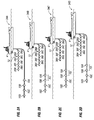
- FIGS 2a-2d illustrate an electromagnetic field modelling technique that includes four different shotpoints 34a-34d for marine electromagnetic survey system 2 in accordance with present embodiments.
- the shotpoints 34a-34d will be referred to herein collectively as shotpoints 34a-34d and individually as first shotpoint 34a, second shotpoint 34b, third shotpoint 34c, and fourth shotpoint 34d. While Figures 2a-2d illustrate a total of four of the shotpoints 34a-34d, it should be understood that embodiments may include more or less than four of the shotpoints 34a-34d.
- bipole source 12 may be towed by survey vessel 4, and bipole source 12 may be represented in the modelling technique by a plurality of dipole sources 36a-36h.
- survey vessel 4 may tow a plurality of electromagnetic sensors 10a-10d.
- the electromagnetic sensors 10a-10d- will be referred to herein collectively as electromagnetic sensors 10a-10d and individually as first electromagnetic sensor 10a, second electromagnetic sensor 10b, third electromagnetic sensor 10c, and fourth electromagnetic sensor 10d.
- Each of electromagnetic sensors 10a-d may record measurements of electromagnetic field properties from an electromagnetic field generated by bipole source 12. The measurement may be, for example, induced voltage, magnetic field amplitude and/or magnetic field gradient, such that the electromagnetic data represent one or more electromagnetic field properties.
- bipole source 12 may be activated to generate an electromagnetic field and measurements of electromagnetic sensors 10 may be recorded, for example, to obtain electromagnetic data.
- bipole source 12 may be modelled as a plurality of dipole sources 36a-36h, for example, to determine a modelled electromagnetic field. Electromagnetic data recorded by each of electromagnetic sensors 10a-10d may be used in modelling of bipole source 12.
- bipole source 12 is modelled as eight dipole sources 36a-36h, but it should be understood that more or less than eight of the dipole sources 36 may be used for modelling of bipole source 12.
- the dipole sources 36a-36h may be referred to collectively as dipole sources 36a-36h and individually as first dipole source 36a, second dipole source 36b, and so forth to eight dipole source 36h.
- each of electromagnetic sensors 10a-10d may be modelled to integrate over nine solutions from each of the dipole sources 36a-36h.
- Figures 2a-2b illustrate four of the electromagnetic sensors 10a-10d, which may lead to an integration of thirty two possible solutions for each of shotpoints 34a-34d to provide an approximation of the electromagnetic field for bipole source 12, as there may be eight dipole sources 36a-36h for the four electromagnetic sensors 10a-10d and each of the dipole-sensor pairs may be solved for.
- Each possible solution may increase the amount of computations in which data processing system 26 (e.g., shown on Figure 1 ) may perform to obtain a modelled electromagnetic field.
- FIG. 2a-2d illustrate a total of four shotpoints 34a-34d, each with a potential of thirty two possible solutions, thus providing an increased computational load to obtain modelled electromagnetic fields. It should be noted that the possible number of solutions may rise and/or fall based on the number of electromagnetic sensors 10a-10d and dipole sources 36a-36h, which may not be limited by this disclosure.
- Each of the shotpoints 34a-34d may be separated by a predetermined spacing, represented by ⁇ S, and there may be any number of shotpoints 34a-34d within a survey area.
- an alternative modelling method may be utilized in accordance with example embodiments.
- the combination of the first dipole source 36a and first electromagnetic sensor 10a in first shotpoint 34a on Figure 2a may be matched by the combination of third dipole source 46c and second electromagnetic sensor 10b in second shotpoint 34b on Figure 2b . Therefore, many dipole-sensor combinations in second shotpoint 34b of Figure 2b and beyond may be modelled in first shotpoint 34a of Figure 2b .
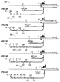
- Figures 3a-3d illustrate an electromagnetic field modelling technique to calculate an approximation of the electromagnetic field for the bipole source 12 that may be utilized to reduce computational loads placed on data processing system 26 (e.g., shown on Figure 1 ) in accordance with example embodiments.
- Embodiments of the electromagnetic field modelling technique may use the overlapping dipole and sensor combinations discussed above with respect to Figures 2a-2d to reduce computational load.
- a total of five shotpoints 34a-34e are illustrated.
- the electromagnetic field modelling technique may be implemented with more or less than five shotpoints 34a-34e, as desired for a particular application.
- the alternative field modelling technique may remove the overlap between shotpoints 34a-d by reducing the modelled length of bipole source 12 for each of the shotpoints 34a-34e and by combining modelled results from many shotpoints, such as shotpoints 34a-34e.
- bipole source 12 may be modelled with a reduced number of dipole sources 36a-36b in the calculation of the approximation of the electromagnetic field of the bipole source 12.
- bipole source 12 may be modelled by first dipole source 36a and second dipole source 36b.
- the length (and number) of dipole sources 36a-36b in each of shotpoints 34a-34e may be reduced such that the dipole sources 36a-36b may only extend a portion of the length of bipole source 12.
- bipole source 12 may be modelled in each of the shotpoints 34a-34e over only a portion of its length, for example, dipole sources 36 may only extend over 50% or less of the length of bipole source 12.
- shotpoints 34a-34e bipole source 12 may increase, which may reconstruct a previous shotpoint 34.
- the number of dipole sources 36a-36b in bipole source 12 may be smaller in embodiments of the alternative field modelling technique described herein.
- the electromagnetic data recorded by each of electromagnetic sensor 10a-10d may have to be integrated over two solutions, as two dipole sources 36a-36b may be present. This may lead to an integration of two possible solutions for each of electromagnetic sensor 10a-10d, significantly reducing the amount of possible solutions across the survey area, for example, as compared to the technique described above with respect to Figures 2a-2d .
- additional sensor points 40 may be added to the calculations of each of shotpoints 34a-34e, as illustrated in Figures 3b-3e .
- the addition of sensor points 40 may extend receiver array 18 to include all bipole-sensor offsets that may be used for an inversion method and its corresponding forward modelling solutions. Extending receiver array 18 may not remove the benefits gained from alternative field modelling technique. The extension may be small because receiver array 18 may be longer than bipole source 12.
- receiver array 18 may be about 8000 meters and bipole source 12 may have a length of 800 meters
- bipole source 12 represented by eight dipole sources 36a-36h e.g., shown on Figures 2a-2d
- an array of two dipole sources 36a-36b e.g., shown on Figures 3a-3d
- receiver array 18 may have length of about 1,000 meters to about 10,000 meters or even longer
- bipole source 12 may have a length of about 100 meters to about 1,000 meters or even longer.
- Modelling techniques for marine electromagnetic surveying provide results for models of receiver arrays 18 that are longer at a smaller computational cost than for bipole sources 12 that are longer. Accordingly, embodiments of the alternative field modelling technique disclosed herein may reduce the computational burden on data processing system 26 (e.g., shown on Figure 1 ), which may allow information and signals recorded by electromagnetic sensors 10a-10d to be processed faster while maintaining a high quality in a final processed product. Reducing the computational burden may provide a number of benefits, including decrease in processing time, power consumption, and/or the amount of processing power required by data processing system 26 (e.g., shown on Figure 1 ).
- an electromagnetic field may be modelled based on electromagnetic data recorded from at least one shotpoint.
- the modelling of the electromagnetic field may result in an approximation of the electromagnetic field for bipole source 12 with less computational burden.
- the modelling may be performed with a data processing system 26 (e.g., shown on FIG. 1 ).
- electromagnetic data may be received from shotpoints 34a-34e of a marine electromagnetic survey.
- the electromagnetic data may include information recorded from one or more electromagnetic sensors 10a-10d.
- the electromagnetic data may be used to model electromagnetic fields for one or more dipole sources 36a-36b of bipole source 12.
- the electromagnetic fields may then be used to determine an approximation of the electromagnetic field for the bipole source.
- a plurality of data points may be combined to provide the approximation of the electromagnetic field, wherein the data points include the electromagnetic fields.
- combining may include integrating according the data points.
- a first electromagnetic field may be modelled based on first electromagnetic data received from first shotpoint 34a of the marine electromagnetic survey.
- the first electromagnetic data received for the first shotpoint 34a may be utilized in modelling the first electromagnetic field for one or more dipole sources 36a-36b of bipole source 12.
- the first electromagnetic data may include information received from one or more electromagnetic sensors 10a-10d.
- a second electromagnetic field may be modelled based on second electromagnetic data received from second shotpoint 34b of the marine electromagnetic survey.
- the second electromagnetic data received for the second shotpoint 34b may be utilized in modelling the second electromagnetic field for one or more dipole sources 36a-36b of the bipole source.
- the second electromagnetic data may include information received from one or more electromagnetic sensors 10a-10d.
- the first electromagnetic field, the second electromagnetic field, and one or more additional data points may be combined. Combining the data points may include integrating across the first electromagnetic field and the second electromagnetic field.
- a third electromagnetic field may be modelled for use in approximating the electromagnetic field for the bipole source 12.
- the third electromagnetic field may be modelled based on third electromagnetic data received from third shotpoint 34c of the marine electromagnetic survey.
- the third electromagnetic data received for the third shotpoint 34c may be utilized in modelling the third electromagnetic field for one or more dipole sources 36a-36b of the bipole source.
- the third electromagnetic data may include information received from one or more electromagnetic sensors 10a-10d.
- the third electromagnetic field may be used as a data point in determining the electromagnetic field for the bipole source 12.
- the third electromagnetic field may be combined with additional data points, such as the first electromagnetic and the second electromagnetic field to provide the approximation of the electromagnetic field of the bipole source 12. Combining the data points may include integrating across the data points.
- a fourth electromagnetic field may be modelled for use in approximating the electromagnetic field for the bipole source 12.
- the fourth electromagnetic field may be modelled based on fourth electromagnetic data received from fourth shotpoint 34d of the marine electromagnetic survey.
- the fourth electromagnetic data received for the fourth shotpoint 34d may be utilized in modelling the fourth electromagnetic field for one or more dipole sources 36a-36b of the bipole source.
- the fourth electromagnetic data may include information received from one or more electromagnetic sensors 10a-10d.
- the fourth electromagnetic field may be used as a data point in determining the electromagnetic field for the bipole source 12.
- the fourth electromagnetic field may be combined with additional data points to provide the approximation of the electromagnetic field of the bipole source 12. Combining the data points may include integrating across the data points.
- a fifth electromagnetic field may be modelled for use in approximating the electromagnetic field for the bipole source 12.
- the fifth electromagnetic field may be modelled based on fifth electromagnetic data received from fifth shotpoint 34e of the marine electromagnetic survey.
- the fifth electromagnetic data received for the fifth shotpoint 34e may be utilized in modelling the fifth electromagnetic field for one or more dipole sources 36a-36b of the bipole source.
- the fifth electromagnetic data may include information received from one or more electromagnetic sensors 10a-10d.
- the fifth electromagnetic field may be used as a data point in determining the electromagnetic field for the bipole source 12.
- the fifth electromagnetic field may be combined with additional data points to provide the approximation of the electromagnetic field of the bipole source 12. Combining the data points may include integrating across the data points.
- This modelling technique represented on Figures 3a-3e may be repeated as many number of times as needed to provide one or more approximations of the electromagnetic field for the bipole source 12. For example, additional electromagnetic data from one or more additional shotpoints of the marine electromagnetic survey may be received. One or more additional electromagnetic fields may be modeled from the additional electromagnetic data at the one or more additional points. To provide another approximation of the electromagnetic field for the bipole source, the one or more additional electromagnetic fields may be combined with at least a portion of the data points that were previously modelled. The inclusion of previously modelled electromagnetic fields for the dipole sources 36a-36b may reduce the computational load on data processing system, which may reduce the time to model an electromagnetic field and increase accuracy.
Landscapes
- Physics & Mathematics (AREA)
- Engineering & Computer Science (AREA)
- Electromagnetism (AREA)
- Remote Sensing (AREA)
- Life Sciences & Earth Sciences (AREA)
- General Physics & Mathematics (AREA)
- Theoretical Computer Science (AREA)
- Geology (AREA)
- General Life Sciences & Earth Sciences (AREA)
- Environmental & Geological Engineering (AREA)
- Geophysics (AREA)
- Geometry (AREA)
- Evolutionary Computation (AREA)
- General Engineering & Computer Science (AREA)
- Computer Hardware Design (AREA)
- Geophysics And Detection Of Objects (AREA)
- Arrangements For Transmission Of Measured Signals (AREA)
- Management, Administration, Business Operations System, And Electronic Commerce (AREA)
- Magnetic Resonance Imaging Apparatus (AREA)
Abstract
Description
- The present application claims the benefit of
U.S. Provisional Application No. 62/246,300, filed October 26, 2015 - One type of marine geophysical surveying includes marine electromagnetic surveying, in which geophysical data may be collected or acquired. Marine electromagnetic surveying is used, among other purposes, to infer spatial distribution of electrical subsurface resistivity of formations below the bottom of a body of water, such as a lake or ocean. The spatial distribution of subsurface resistivity is used to assist in determining the presence of hydrocarbon-bearing formations in the subsurface, potentially resulting in cost saving by better targeted drilling operations. Marine electromagnetic surveying generally includes inducing an electromagnetic field in the subsurface formations (e.g., by injecting electrical current in the water), and measuring one or more parameters related to a response of the subsurface formations to the induced electromagnetic field, the response referred to herein as an "electromagnetic earth response." The current may diffuse through the sea water and subsurface formation with an electric potential difference caused by the current measured at some distance away from the electromagnetic source. The resulting electric potential difference may be measured using electromagnetic sensors, for example, that may be distributed on one or more streamers towed by a survey vessel, located on one or more ocean bottom cables, or fixed at nodes at or near a water bottom. The sensitivity of the potential difference to the subsurface resistivity may depend on the sensor offsets and the source signal frequencies.
- Data may be collected from the marine electromagnetic survey to obtain information about the subsurface resistivities. The goal is typically to determine the subsurface resistivities as accurately as possible. Determination of the subsurface resistivities using the collected data commonly includes two major steps, commonly referred to as processing and inversion. Processing may be focused on providing good estimates of electromagnetic earth responses while suppressing ambient electromagnetic noise. Inversion may use the estimates of electromagnetic earth responses provided by the processing to search for a distribution of subsurface resistivities that may best fit the electromagnetic earth responses, or the inversion may use the recorded data without previous processing. In examples, the inversion for subsurface resistivities may require the computation of many forward results, which may be computations of synthetic data for a modelled distribution of subsurface resistivities. The processing and inversion may be slowed by the amount of computation used for performing processing and inversion methodologies by a data processing system, which may slow the delivery of a final product to a customer.
- These drawings illustrate certain aspects of some of the embodiments of the present disclosure and may not be used to limit or define the disclosure.
-
Figure 1 illustrates an example embodiment of a marine electromagnetic survey system; -
Figure 2a illustrates a first shotpoint for use in modelling a bipole source; -
Figure 2b illustrates a second shotpoint for use in modelling the bipole source; -
Figure 2c illustrates a third shotpoint for use in modelling the bipole source; -
Figure 2d illustrates a fourth shotpoint for use in modelling the bipole source; -
Figure 3a illustrates a first shotpoint for use in an alternative technique for modelling the bipole source; -
Figure 3b illustrates a second shotpoint for use in an alternative technique for modelling the bipole source ; -
Figure 3c illustrates a third shotpoint for use in an alternative technique for modelling the bipole source; -
Figure 3d illustrates a fourth shotpoint for use in an alternative technique for modelling the bipole source; and -
Figure 3e illustrates a fifth shotpoint for use in an alternative technique for modelling the bipole source. - It is to be understood that the present disclosure is not limited to particular devices or methods, which may, of course, vary. It is also to be understood that the terminology used herein is for the purpose of describing particular embodiments only, and is not intended to be limiting. As used herein, the singular forms "a", "an", and "the" include singular and plural referents unless the content clearly dictates otherwise. Furthermore, the word "may" is used throughout this application in a permissive sense (i.e., having the potential to, being able to), not in a mandatory sense (i.e., must). The term "include," and derivations thereof, mean "including, but not limited to." The term "coupled" means directly or indirectly connected.
- The present disclosure relates to marine electromagnetic surveying and, more particularly, to methods of reducing computational loads generated by processing and inversion methodologies. As used herein, the term "inversion" generally refers to the solution to an "inverse problem," wherein an inverse problem is the process of calculating from a set of observations the causal factors that produced them. Commonly, inversion may be implemented as an iterative search for a set of factors, or values of parameters describing these factors, that may fit the observations. Often, an inverse problem does not have a unique solution. In embodiments, the "causal factors" of primary interest in marine electromagnetic surveying may be subsurface resistivities, and the process of estimating them is referred to as an inversion. The term "inversion" is used when the input may not be the observations themselves but the results from processing the observations. As used herein, the term "processing" refers to the calculation of electromagnetic earth responses from observations, with the aim of suppressing the ambient electromagnetic noise. In the present disclosure, this processing is distinct from inversion and is used to refer to disambiguation.
- Disclosed below is a method which may include receiving a first electromagnetic data from a first shotpoint of a marine electromagnetic survey, receiving second electromagnetic data from a second shotpoint of the marine electromagnetic survey, modelling a first electromagnetic field for one or more dipole sources of a bipole source from the first electromagnetic data, modelling a second electromagnetic field for the one or more dipole sources from the second electromagnetic data, and combining a plurality of data points to provide an approximation of an electromagnetic field for the bipole source, wherein the data points include the first electromagnetic field and the second electromagnetic field.
- Disclosed below is a method for manufacturing a geophysical data product which may include receiving, with the data processing system, electromagnetic data from a plurality of shotpoints of a marine electromagnetic survey. Modelling, with the data processing system, electromagnetic fields for one or more dipole sources of a bipole source from the electromagnetic data and combining, with the data processing system, a plurality of data points to provide an approximation of an electromagnetic field for the bipole source, wherein the data points include the electromagnetic fields for the one or more dipole sources; and recording, with the data processing system, the approximation of the electromagnetic field for the bipole source on one or more non-transitory computer readable media thereby creating the geophysical data product.
- Disclosed below is an electromagnetic survey system, which may include electromagnetic sensors, a bipole source, wherein the bipole source includes a pair of electrodes that are separated by a distance, wherein the bipole source is configured to generate an electromagnetic field. A data processing system configured to receive electromagnetic data from a plurality of shotpoints of the bipole source, model electromagnetic fields for one or more dipole sources of the bipole source from the electromagnetic data and combine a plurality of data points to provide an approximation of the electromagnetic field for the bipole source, wherein the data points include the electromagnetic fields for the one or more dipole sources.
- Discussed below is a non-transitory computer-readable medium encoded with machine-readable instructions to control one or more processors of a data processing system to perform the operations of: receiving electromagnetic data from a plurality of shotpoints of a marine electromagnetic survey; modelling electromagnetic fields for one or more dipole sources of a bipole source from the electromagnetic data; and combining a plurality of data points to provide an approximation of an electromagnetic field for the bipole source, wherein the data points comprise the electromagnetic fields for the one or more dipole sources.
- Referring now to
Figure 1 , a marine electromagnetic survey system 2 may be illustrated in accordance with example embodiments. As illustrated, marine electromagnetic survey system 2 may include asurvey vessel 4 moving along the surface of a body ofwater 6, such as a lake or ocean.Survey vessel 4 may include thereon equipment, shown generally at 8 and referred to for convenience as an "information handling system."Information handling system 8 may include devices (none shown separately) for navigatingsurvey vessel 4, such as global positioning system ("GPS") receivers, for actuating at least onebipole source 12, and for recording signals generated byelectromagnetic sensors 10. The term "bipole" may describe a source in whichelectrodes 13, discussed below, may be separated by a non-negligible distance in terms of an electromagnetic field generated atelectromagnetic sensors 10. By contrast, the term "dipole" may describe an electromagnetic source, be it real or modelled, in whichelectrodes 13 may be separated by a negligible distance, and therefore may be considered a point source. -
Bipole sources 12 in modelling may be represented by an array of dipole sources, and the electromagnetic field generated by abipole source 12 may be modelled by integrating (summing) the electromagnetic fields generated by each dipole source in the equivalent array. At a distance,bipole sources 12 in a modelled electromagnetic field may be indistinguishable. Using an array of dipole sources may be a method to model abipole source 12. -
Survey vessel 4 and/or a different vessel (not shown) may tow at least onebipole source 12. In the illustrated embodiment,bipole source 12 may be towed abovewater bottom 16, whereinbipole source 12 is disconnected fromwater bottom 16. Bipolesource 12 may include a pair ofelectrodes 13 that are spaced apart a distance D, which is preselected. At selectedtimes bipole source 12 may be actuated to generate an electromagnetic field that travels downwardly through the body ofwater 6 and formations 14 belowwater bottom 16. Specifically,bipole source 12 may be activated to generate an electromagnetic field. In examples,bipole source 12 may include a pair ofelectrodes 13. Theelectrodes 13 may be separated by any suitable distance D that would be considered a non-negligible distance. A suitable distance of distance D may be about one hundred meters or longer, about two hundred meters or longer, or about five hundred meters or longer. By way of example, theelectrodes 13 may be separated by a distance D of about one hundred meters to about one thousand meters, about two hundred meters to about one thousand meters, and/or about five hundred meters to about one thousand meters. Without limitation, bipolesource 12 may increase in strength over a longer length. - In some embodiments,
survey vessel 4 may further tow areceiver array 18 including a plurality ofelectromagnetic sensors 10 at spaced apart positions. In the illustrated embodiment,receiver array 18 may be located on a single receiver cable, or "streamer" shown generally at 20, configured to be towable from thesurvey vessel 4 moving on the surface of the body ofwater 6. In other embodiments,receiver array 18 may be located onmultiple streamers 20 displaced horizontally and/or vertically from one another. In alternative embodiments,receiver array 18 may includeelectromagnetic sensors 10 located on ocean bottom cables and/or nodes, fixed at or near water bottom 16, either in lieu of or in addition toelectromagnetic sensors 10 on streamer 20 (or multiple streamers 20). In still other embodiments, additionalelectromagnetic sensors 10 may be located onstreamers 20 towed by another vessel (not shown). As another alternative, one or more additional streamers (not shown) may be towed behindsurvey vessel 4, towed behind another vessel (not shown), located on an ocean bottom cable, or on nodes fixed at or nearwater bottom 16. Non-limiting examples ofelectromagnetic sensors 10 may include electromagnetic field sensors, such as receiver electrodes and magnetometers. The type(s) and configurations(s) ofelectromagnetic sensors 10 are not intended to limit the scope of the disclosure. Without limitation,electromagnetic sensors 10 may be used, for example, to acquire electromagnetic data, such as measurements of the potential difference influenced by the electromagnetic earth response offormations 14 belowwater bottom 16. Specifically, electromagnetic data may be acquired from the marine electromagnetic survey system 2 using theelectromagnetic sensors 10.Electromagnetic sensors 10 may measure one or more various electromagnetic field properties, such as voltage, magnetic field amplitude, and/or magnetic field gradient. -
Streamer 20 may be coupled at its forward end (with respect to direction of movement of the survey vessel 4) to atermination 22 which may couple thestreamer 20 to a lead-incable 24. Lead-incable 24 may transmit towing force, power, and/or signals betweensurvey vessel 4 andstreamer 20. While not illustrated,streamer 20 may include a number of different devices in addition toelectromagnetic sensors 10, such as lateral force and depth control devices (e.g., birds having variable incidence wings) to regulatestreamer 20 depth, seismic sensors, depth sensors, velocity sensors, accelerometers, magnetometers, and/or positions sensors, among others. While only asingle streamer 20 may be shown, it may be understood that the disclosure is applicable to areceiver array 18 that includes any number of laterally spaced apartstreamers 20 towed bysurvey vessel 4 and/or any other vessel. For example, in some embodiments, two or more of thestreamers 20 may be laterally spaced apart and towed bysurvey vessel 4. "Lateral" or "laterally," in the present context, means transverse to the direction of the motion ofsurvey vessel 4. Lateral positioning ofstreamers 20 may be maintained by various towed devices (e.g., deflectors, paravanes, doors, etc.) that may generate lateral force as moved through body ofwater 6. In some embodiments, multiple laterally spaced apartstreamers 20 may be towed bysurvey vessel 4. Accordingly, the number ofstreamers 20 and their particular geometric configuration in body ofwater 6 may not considered a limitation on the scope of the present disclosure. - As previously disclosed,
electromagnetic sensors 10 may be used to acquire electromagnetic data. The electromagnetic data may contain measurements of various electric field properties of the electromagnetic field generated as a result of the interaction of the induced electromagnetic field withformations 14 belowwater bottom 16. The measurement may be, for example, induced voltage, magnetic field amplitude and/or magnetic field gradient, such that the electromagnetic data represent one or more electromagnetic field properties.Electromagnetic sensors 10 may acquire electromagnetic data whenbipole source 12 generates a source signal. The source signal may be single pulses and/or continuous sweeps of electromagnetic energy. A marine electromagnetic survey typically may include several lines (paths of travel for survey vessel 4) planned to cover the area under consideration with sufficient spatial sampling density. Each line may be divided into shots, where, for a marine electromagnetic survey, a shot may be a spatial sample point for which an electromagnetic earth response may be estimated, rather than a physical "shot" in the seismic sense. In a marine electromagnetic survey, the source signal may be continuous for the whole line, and may be of a single frequency and/or amplitude, or continuously varying. Each electromagnetic shot thus may include one sequence of time domain samples perelectromagnetic sensor 10. The source signal frombipole source 12 may also be measured separately. - In accordance with an embodiment of the disclosure, a geophysical data product indicative of certain properties of the
formations 14 may be manufactured from the measured electromagnetic signal and electromagnetic earth response thereto. The geophysical data product may include acquired and/or processed electromagnetic data and may be recorded on one or more non-transitory computer readable media. In some embodiments, the geophysical data product may include an approximation of the electromagnetic field forbipole source 12. The geophysical data product may be produced offshore (i.e. by equipment on a vessel) or onshore (i.e. at a facility on land) either within the United States and/or in another country. Specifically, embodiments may include producing a geophysical data product from at least the subsurface resistivities and storing the geophysical data product on a non-transitory computer readable media for importing onshore. If the geophysical data product is produced offshore and/or in another country, it may be imported onshore to a facility in, for example, the United States or another country. Once onshore in, for example, the United States or another country, further processing and/or geophysical analysis may be performed on the geophysical data product. - Geophysical analysis of the geophysical data may be performed by an inversion methodology. In some embodiments, inversion methodologies may include gradient based local searching, stochastic global searching, and/or Newton based search methods. Most methodologies may be performed by computations performed by
information handling system 8.Figure 1 illustratesinformation handling system 8, which may further include adata processing system 26 that may be utilized in accordance with examples of the present disclosure. Without limitation,information handling system 8 may be disposed onsurvey vessel 4, another vessel, and/or onshore.Information handling system 8 may include any instrumentality or aggregate of instrumentalities operable to compute, classify, process, transmit, receive, retrieve, originate, switch, store, display, manifest, detect, record, reproduce, handle, or utilize any form of information, intelligence, or data for business, scientific, control, or other purposes. For example,information handling system 8 may be a personal computer, a network storage device, or any other suitable device and may vary in size, shape, performance, functionality, and price.Data processing system 26 may be used for implementation of inversion methodologies. Special or unique software for receiving the inputs, data processing, and sending output signals may be stored indata processing system 26 and/or on non-transitory computerreadable media 32. Those of ordinary skill in the art will appreciate thatdata processing system 26 may include hardware elements including circuitry, software elements including computer code stored on the non-transitory computerreadable media 32 or a combination of both hardware and software elements. A processor, not illustrated, such as a central processing unit or CPU, may control the overall operation ofdata processing system 26. -
Data processing system 26 may include random access memory (RAM), one or more processing resources (e.g. a microprocessor) such as a central processing unit (CPU) or hardware or software control logic, ROM, and/or other types of nonvolatile memory. Additional components ofinformation handling system 8 may include one or more of adisplay device 30, an input device 28 (e.g., keyboard, mouse, etc.) as well as non-transitory computer readable media 32 (e.g., optical disks, magnetic disks) that may store code representative of the above-described methods.Information handling system 8 may also include one or more buses (not shown) operable to transmit communications between the various hardware components.Information handling system 8 may act as a data acquisition system and possibly a data processing system that analyzes measurements, for example, to process one or more properties of an inversion methodology.Data processing system 26 may compute processes such as modelling of electromagnetic fields. Modelling of electromagnetic fields may also be referred to as "forward modelling", wherein forward modelling may be defined as calculating the electric field atelectromagnetic sensors 10. Forward modeling may include selecting a set of model parameters and solving a system of equations with the selected model parameters using obtained electromagnetic data. The system of equations may include appropriate versions of Maxwell's equations for marine electromagnetic surveys. Modelling of electromagnetic fields may be based on results from a marine electromagnetic survey, or at least compared to the results from a marine electromagnetic survey for the purpose and may be used in a process of inferring subsurface resistivities through the process of inversion. The marine electromagnetic survey may measure an electromagnetic field based at least in part onbipole source 12 andelectromagnetic sensors 10.Bipole source 12 may includeelectrodes 13 separated by a non-negligible distance, a modelled electromagnetic field may be obtained by integrating the results from several modelled zero length (dipole) sources, distributed over the length of thebipole source 12. - Forward modelling of an electromagnetic field from electromagnetic data found in a marine electromagnetic survey for
receiver array 18 may be based on spatial sampling, which may be identified as a distribution of "shotpoints." For example, in modelling, an electromagnetic source, bipolesource 12, which may stretch for a distance D of hundreds of meters, may be modelled as a plurality of dipole sources (e.g., dipole sources 36 onFigures 2a-2d ) at a single point along the actual length of thebipole source 12. For each shotpoint, the position ofbipole source 12 andelectromagnetic sensors 10 may serve as the bases for calculating a modelled electromagnetic field. -
Figures 2a-2d illustrate an electromagnetic field modelling technique that includes four different shotpoints 34a-34d for marine electromagnetic survey system 2 in accordance with present embodiments. The shotpoints 34a-34d will be referred to herein collectively as shotpoints 34a-34d and individually as first shotpoint 34a, second shotpoint 34b, third shotpoint 34c, and fourth shotpoint 34d. WhileFigures 2a-2d illustrate a total of four of the shotpoints 34a-34d, it should be understood that embodiments may include more or less than four of the shotpoints 34a-34d. As illustrated, bipolesource 12 may be towed bysurvey vessel 4, andbipole source 12 may be represented in the modelling technique by a plurality of dipole sources 36a-36h. Additionally,survey vessel 4 may tow a plurality of electromagnetic sensors 10a-10d. The electromagnetic sensors 10a-10d- will be referred to herein collectively as electromagnetic sensors 10a-10d and individually as first electromagnetic sensor 10a, second electromagnetic sensor 10b, third electromagnetic sensor 10c, and fourth electromagnetic sensor 10d. Each of electromagnetic sensors 10a-d may record measurements of electromagnetic field properties from an electromagnetic field generated bybipole source 12. The measurement may be, for example, induced voltage, magnetic field amplitude and/or magnetic field gradient, such that the electromagnetic data represent one or more electromagnetic field properties. Accordingly, for each of the shotpoint 34a-34d, bipolesource 12 may be activated to generate an electromagnetic field and measurements ofelectromagnetic sensors 10 may be recorded, for example, to obtain electromagnetic data. - With continued reference to
Figures 2a-2d , bipolesource 12 may be modelled as a plurality of dipole sources 36a-36h, for example, to determine a modelled electromagnetic field. Electromagnetic data recorded by each of electromagnetic sensors 10a-10d may be used in modelling ofbipole source 12. In the illustrated embodiment, bipolesource 12 is modelled as eight dipole sources 36a-36h, but it should be understood that more or less than eight of the dipole sources 36 may be used for modelling ofbipole source 12. The dipole sources 36a-36h may be referred to collectively as dipole sources 36a-36h and individually as first dipole source 36a, second dipole source 36b, and so forth to eight dipole source 36h. Thus, the electromagnetic data recorded by each of electromagnetic sensors 10a-10d may be modelled to integrate over nine solutions from each of the dipole sources 36a-36h. Without limitation,Figures 2a-2b illustrate four of the electromagnetic sensors 10a-10d, which may lead to an integration of thirty two possible solutions for each of shotpoints 34a-34d to provide an approximation of the electromagnetic field forbipole source 12, as there may be eight dipole sources 36a-36h for the four electromagnetic sensors 10a-10d and each of the dipole-sensor pairs may be solved for. Each possible solution may increase the amount of computations in which data processing system 26 (e.g., shown onFigure 1 ) may perform to obtain a modelled electromagnetic field. Additionally, the computations may be repeated for each of the shotpoints 34a-34d so that a modelled electromagnetic field may be obtained for each of the shotpoints 34a-34d.Figures 2a-2d illustrate a total of four shotpoints 34a-34d, each with a potential of thirty two possible solutions, thus providing an increased computational load to obtain modelled electromagnetic fields. It should be noted that the possible number of solutions may rise and/or fall based on the number of electromagnetic sensors 10a-10d and dipole sources 36a-36h, which may not be limited by this disclosure. Each of the shotpoints 34a-34d may be separated by a predetermined spacing, represented by ΔS, and there may be any number of shotpoints 34a-34d within a survey area. - In an effort to reduce computational loads, an alternative modelling method may be utilized in accordance with example embodiments. As illustrated in the embodiments of
Figures 2a-2d , there may be several dipole-sensor combinations that model each of shotpoints 34a-34d. For example, the combination of the first dipole source 36a and first electromagnetic sensor 10a in first shotpoint 34a onFigure 2a may be matched by the combination of third dipole source 46c and second electromagnetic sensor 10b in second shotpoint 34b onFigure 2b . Therefore, many dipole-sensor combinations in second shotpoint 34b ofFigure 2b and beyond may be modelled in first shotpoint 34a ofFigure 2b . Likewise, there may be additional overlap in third shotpoint 34c ofFigure 2c and fourth shotpoint 34d ofFigure 2d for various dipole and sensor combinations. -
Figures 3a-3d illustrate an electromagnetic field modelling technique to calculate an approximation of the electromagnetic field for thebipole source 12 that may be utilized to reduce computational loads placed on data processing system 26 (e.g., shown onFigure 1 ) in accordance with example embodiments. Embodiments of the electromagnetic field modelling technique may use the overlapping dipole and sensor combinations discussed above with respect toFigures 2a-2d to reduce computational load. In the illustrated embodiment, a total of five shotpoints 34a-34e are illustrated. However, it should be understood that the electromagnetic field modelling technique may be implemented with more or less than five shotpoints 34a-34e, as desired for a particular application. The alternative field modelling technique may remove the overlap between shotpoints 34a-d by reducing the modelled length ofbipole source 12 for each of the shotpoints 34a-34e and by combining modelled results from many shotpoints, such as shotpoints 34a-34e. As illustrated inFigures 3a-3d , that correspond to the scenario inFigures 2a-2d , bipolesource 12 may be modelled with a reduced number of dipole sources 36a-36b in the calculation of the approximation of the electromagnetic field of thebipole source 12. As illustrated, bipolesource 12 may be modelled by first dipole source 36a and second dipole source 36b. The length (and number) of dipole sources 36a-36b in each of shotpoints 34a-34e may be reduced such that the dipole sources 36a-36b may only extend a portion of the length ofbipole source 12. For example, bipolesource 12 may be modelled in each of the shotpoints 34a-34e over only a portion of its length, for example, dipole sources 36 may only extend over 50% or less of the length ofbipole source 12. By combination of shotpoints 34a-34e, bipolesource 12 may increase, which may reconstruct a previous shotpoint 34. Without limitation, there may be any number of dipole sources 36a-36b inbipole source 12. However, the number of dipole sources 36a-36b inbipole source 12 may be smaller in embodiments of the alternative field modelling technique described herein. Thus, the electromagnetic data recorded by each of electromagnetic sensor 10a-10d may have to be integrated over two solutions, as two dipole sources 36a-36b may be present. This may lead to an integration of two possible solutions for each of electromagnetic sensor 10a-10d, significantly reducing the amount of possible solutions across the survey area, for example, as compared to the technique described above with respect toFigures 2a-2d . - To maintain coverage for the integration for all of shotpoints 34a-34e, additional sensor points 40, may be added to the calculations of each of shotpoints 34a-34e, as illustrated in
Figures 3b-3e . In example embodiments, the addition of sensor points 40 may extendreceiver array 18 to include all bipole-sensor offsets that may be used for an inversion method and its corresponding forward modelling solutions. Extendingreceiver array 18 may not remove the benefits gained from alternative field modelling technique. The extension may be small becausereceiver array 18 may be longer thanbipole source 12. For example, assumingreceiver array 18 may be about 8000 meters andbipole source 12 may have a length of 800 meters, in one particular implementation, if bipolesource 12 represented by eight dipole sources 36a-36h (e.g., shown onFigures 2a-2d ) may be instead modelled with an array of two dipole sources 36a-36b (e.g., shown onFigures 3a-3d ) at the expense of extending the model ofreceiver array 18 by 800 meters, there may be a ten percent expense to gain a fourfold modelling reduction. It should be understood that these lengths are merely examples and embodiments ofreceiver array 18 may have length of about 1,000 meters to about 10,000 meters or even longer and embodiments ofbipole source 12 may have a length of about 100 meters to about 1,000 meters or even longer. Modelling techniques for marine electromagnetic surveying provide results for models ofreceiver arrays 18 that are longer at a smaller computational cost than forbipole sources 12 that are longer. Accordingly, embodiments of the alternative field modelling technique disclosed herein may reduce the computational burden on data processing system 26 (e.g., shown onFigure 1 ), which may allow information and signals recorded by electromagnetic sensors 10a-10d to be processed faster while maintaining a high quality in a final processed product. Reducing the computational burden may provide a number of benefits, including decrease in processing time, power consumption, and/or the amount of processing power required by data processing system 26 (e.g., shown onFigure 1 ). - Referring to
Figures 3a-3e , an electromagnetic field may be modelled based on electromagnetic data recorded from at least one shotpoint. In accordance with present embodiments, the modelling of the electromagnetic field may result in an approximation of the electromagnetic field forbipole source 12 with less computational burden. The modelling may be performed with a data processing system 26 (e.g., shown onFIG. 1 ). In some embodiments, electromagnetic data may be received from shotpoints 34a-34e of a marine electromagnetic survey. The electromagnetic data may include information recorded from one or more electromagnetic sensors 10a-10d. In embodiments, the electromagnetic data may be used to model electromagnetic fields for one or more dipole sources 36a-36b ofbipole source 12. The electromagnetic fields may then be used to determine an approximation of the electromagnetic field for the bipole source. For example, a plurality of data points may be combined to provide the approximation of the electromagnetic field, wherein the data points include the electromagnetic fields. In some embodiments, combining may include integrating according the data points. - Referring to
Figure 3a , in some embodiments, a first electromagnetic field may be modelled based on first electromagnetic data received from first shotpoint 34a of the marine electromagnetic survey. The first electromagnetic data received for the first shotpoint 34a may be utilized in modelling the first electromagnetic field for one or more dipole sources 36a-36b ofbipole source 12. The first electromagnetic data may include information received from one or more electromagnetic sensors 10a-10d. Turning now toFigure 3b , in some embodiments, a second electromagnetic field may be modelled based on second electromagnetic data received from second shotpoint 34b of the marine electromagnetic survey. The second electromagnetic data received for the second shotpoint 34b may be utilized in modelling the second electromagnetic field for one or more dipole sources 36a-36b of the bipole source. The second electromagnetic data may include information received from one or more electromagnetic sensors 10a-10d. To provide an approximation of the electromagnetic field of thebipole source 12, the first electromagnetic field, the second electromagnetic field, and one or more additional data points may be combined. Combining the data points may include integrating across the first electromagnetic field and the second electromagnetic field. - Referring to
Figure 3c , in some embodiments, a third electromagnetic field may be modelled for use in approximating the electromagnetic field for thebipole source 12. For example, the third electromagnetic field may be modelled based on third electromagnetic data received from third shotpoint 34c of the marine electromagnetic survey. The third electromagnetic data received for the third shotpoint 34c may be utilized in modelling the third electromagnetic field for one or more dipole sources 36a-36b of the bipole source. The third electromagnetic data may include information received from one or more electromagnetic sensors 10a-10d. The third electromagnetic field may be used as a data point in determining the electromagnetic field for thebipole source 12. For example, the third electromagnetic field may be combined with additional data points, such as the first electromagnetic and the second electromagnetic field to provide the approximation of the electromagnetic field of thebipole source 12. Combining the data points may include integrating across the data points. - Referring to
Figure 3d , in some embodiments, a fourth electromagnetic field may be modelled for use in approximating the electromagnetic field for thebipole source 12. For example, the fourth electromagnetic field may be modelled based on fourth electromagnetic data received from fourth shotpoint 34d of the marine electromagnetic survey. The fourth electromagnetic data received for the fourth shotpoint 34d may be utilized in modelling the fourth electromagnetic field for one or more dipole sources 36a-36b of the bipole source. The fourth electromagnetic data may include information received from one or more electromagnetic sensors 10a-10d. The fourth electromagnetic field may be used as a data point in determining the electromagnetic field for thebipole source 12. For example, the fourth electromagnetic field may be combined with additional data points to provide the approximation of the electromagnetic field of thebipole source 12. Combining the data points may include integrating across the data points. - Referring to
Figure 3e , in some embodiments, a fifth electromagnetic field may be modelled for use in approximating the electromagnetic field for thebipole source 12. For example, the fifth electromagnetic field may be modelled based on fifth electromagnetic data received from fifth shotpoint 34e of the marine electromagnetic survey. The fifth electromagnetic data received for the fifth shotpoint 34e may be utilized in modelling the fifth electromagnetic field for one or more dipole sources 36a-36b of the bipole source. The fifth electromagnetic data may include information received from one or more electromagnetic sensors 10a-10d. The fifth electromagnetic field may be used as a data point in determining the electromagnetic field for thebipole source 12. For example, the fifth electromagnetic field may be combined with additional data points to provide the approximation of the electromagnetic field of thebipole source 12. Combining the data points may include integrating across the data points. - This modelling technique represented on
Figures 3a-3e may be repeated as many number of times as needed to provide one or more approximations of the electromagnetic field for thebipole source 12. For example, additional electromagnetic data from one or more additional shotpoints of the marine electromagnetic survey may be received. One or more additional electromagnetic fields may be modeled from the additional electromagnetic data at the one or more additional points. To provide another approximation of the electromagnetic field for the bipole source, the one or more additional electromagnetic fields may be combined with at least a portion of the data points that were previously modelled. The inclusion of previously modelled electromagnetic fields for the dipole sources 36a-36b may reduce the computational load on data processing system, which may reduce the time to model an electromagnetic field and increase accuracy. - Therefore, the present disclosure may be well adapted to attain the ends and advantages mentioned as well as those that are inherent therein. The particular embodiments disclosed above are illustrative only, as the present disclosure may be modified and practiced in different but equivalent manners apparent to those skilled in the art having the benefit of the teachings herein. Although individual embodiments are discussed, the disclosure covers all combinations of all those embodiments. Furthermore, no limitations are intended to the details of construction or design herein shown, other than as disclosed in the claims below. It is therefore evident that the particular illustrative embodiments disclosed above may be altered or modified and all such variations are considered within the scope and spirit of the present disclosure. All numbers and ranges disclosed above may vary by some amount. Whenever a numerical range with a lower limit and an upper limit is disclosed, any number and any included range falling within the range are specifically disclosed. Moreover, the indefinite articles "a" or "an," as used in the claims, are defined herein to mean one or more than one of the element that it introduces. Also, the terms in the claims have their plain, ordinary meaning unless otherwise explicitly and clearly defined by the patentee. If there is any conflict in the usages of a word or term in this specification and one or more patent or other documents that may be incorporated herein by reference, the definitions that are consistent with this specification may be adopted for the purposes of understanding this disclosure.
Claims (20)
- A method, comprising:receiving first electromagnetic data from a first shotpoint of a marine electromagnetic survey;receiving second electromagnetic data from a second shotpoint of the marine electromagnetic survey;modelling a first electromagnetic field for one or more dipole sources of a bipole source from the first electromagnetic data;modelling a second electromagnetic field for the one or more dipole sources from the second electromagnetic data; andcombining a plurality of data points to provide an approximation of an electromagnetic field for the bipole source, wherein the plurality of data points comprise the first electromagnetic field and the second electromagnetic field.
- The method of claim 1, further comprising receiving third electromagnetic data from a third shotpoint of the marine electromagnetic survey, and modelling a third electromagnetic field for the one or more dipole sources from the third electromagnetic data, wherein the plurality of data points further comprise the third electromagnetic field.
- The method of claim 2, further comprising receiving fourth electromagnetic data from a fourth shotpoint of the marine electromagnetic survey, and modelling a fourth electromagnetic field for the one or more dipole sources from the fourth electromagnetic data, wherein the plurality of data points further comprise the fourth electromagnetic field.
- The method of claim 3, further comprising receiving additional electromagnetic data from an additional shotpoint of the marine electromagnetic survey, and modelling an additional electromagnetic field for the one or more dipole sources from the additional electromagnetic data, and combining the additional electromagnetic field with at least a portion of the plurality of data points to provide another approximation of the electromagnetic field for the bipole source.
- The method of any of the preceding claims, further comprising activating the bipole source at a plurality of shotpoints and collecting electromagnetic data for each of the plurality of shotpoints, wherein the shotpoints comprise the first shotpoint and the second shotpoint.
- The method of any of the preceding claims, further comprising recording the approximation of the electromagnetic field on one or more non-transitory computer readable media thereby creating a geophysical data product.
- The method of any of the preceding claims, wherein the first electromagnetic data and the second electromagnetic data each comprise measurements of a potential difference.
- An electromagnetic survey system, comprisinga data processing system configured to receive electromagnetic data from a plurality of shotpoints of a bipole source, model electromagnetic fields for one or more dipole sources of the bipole source from the electromagnetic data; and combine a plurality of data points to provide an approximation of an electromagnetic field for the bipole source, wherein the data points comprise the electromagnetic fields for the one or more dipole sources.
- The electromagnetic survey system of claim 8, further comprising a survey vessel, electromagnetic sensors coupled to the survey vessel, and a bipole source coupled to the survey vessel, wherein the bipole source comprise a pair of electrodes that are separated by a distance, wherein the bipole source is configured to generate the electromagnetic field.
- The electromagnetic survey system of claim 8 or claim 9, wherein the data processing system being configured to combine the plurality of data points comprises the data processing system being configured to integrate across the plurality of data points.
- A method to manufacture a geophysical data product, comprising:receiving, with a data processing system, electromagnetic data from a plurality of shotpoints of a marine electromagnetic survey;modelling, with the data processing system, electromagnetic fields for one or more dipole sources of a bipole source from the electromagnetic data;combining, with the data processing system, a plurality of data points to provide an approximation of an electromagnetic field for the bipole source, wherein the data points comprise the electromagnetic fields for the one or more dipole sources; andrecording, with the data processing system, the approximation of the electromagnetic field for the bipole source on one or more non-transitory computer readable media thereby creating the geophysical data product.
- The method of claim 11. further comprising importing the geophysical data product onshore and performing further data processing or geophysical analysis on the geophysical data product.
- The method of claim 11, further comprising, receiving, with the data processing system, third electromagnetic data from a third shotpoint of the marine electromagnetic survey and modelling, with the data processing system, a third electromagnetic field for the one or more dipole sources from the third electromagnetic data, wherein the plurality of data points further comprise the third electromagnetic field.
- The method of claim 13, further comprising receiving, with the data processing system, system, fourth electromagnetic data from a fourth shotpoint of the marine electromagnetic survey, and modelling, with the data processing system, a fourth electromagnetic field for the one or more dipole sources from the fourth electromagnetic data, wherein the plurality of data points further comprise the fourth electromagnetic field.
- The method of claim 14, further comprising receiving, with the data processing system, additional electromagnetic data from an additional shotpoint of the marine electromagnetic survey, and modelling, with the data processing system, an additional electromagnetic field from the additional electromagnetic data at the additional shotpoint, and combining the additional electromagnetic field with at least a portion of the data points to provide another approximation of the electromagnetic field for the bipole source.
- The method of any of claims 1 to 7 or any of claims 11 to 15, wherein the combining the plurality of data points comprises integrating across the plurality of data points.
- The method of any of claims 1 to 7 or any of claims 11 to 16, wherein the bipole source comprises a pair of electrodes separated by a distance of about 100 meters to about 1,000 meters.
- A non-transitory computer-readable medium encoded with machine-readable instructions to control one or more processors of a data processing system to perform the operations of:receiving electromagnetic data from a plurality of shotpoints of a marine electromagnetic survey;modelling electromagnetic fields for one or more dipole sources of a bipole source from the electromagnetic data; andcombining a plurality of data points to provide an approximation of an electromagnetic field for the bipole source, wherein the data points comprise the electromagnetic fields for the one or more dipole sources.
- The non-transitory computer-readable medium of claim 18, wherein the combining a plurality of data points comprises integrating across the plurality of data points.
- The non-transitory computer-readable medium of claim 18 or claim 19 wherein the operations performed are those of the method according to any of claims 1 to 7 or any of claims 11 to 17.
Applications Claiming Priority (2)
| Application Number | Priority Date | Filing Date | Title |
|---|---|---|---|
| US201562246300P | 2015-10-26 | 2015-10-26 | |
| US15/280,739 US10878142B2 (en) | 2015-10-26 | 2016-09-29 | Bipole source modeling |
Publications (1)
| Publication Number | Publication Date |
|---|---|
| EP3163329A1 true EP3163329A1 (en) | 2017-05-03 |
Family
ID=57184382
Family Applications (1)
| Application Number | Title | Priority Date | Filing Date |
|---|---|---|---|
| EP16195161.1A Withdrawn EP3163329A1 (en) | 2015-10-26 | 2016-10-21 | Bipole source modeling for marine electromagnetic surveying |
Country Status (6)
| Country | Link |
|---|---|
| US (1) | US10878142B2 (en) |
| EP (1) | EP3163329A1 (en) |
| AU (1) | AU2016247148A1 (en) |
| BR (1) | BR102016024118B1 (en) |
| MX (1) | MX373531B (en) |
| SG (2) | SG10201608637UA (en) |
Cited By (1)
| Publication number | Priority date | Publication date | Assignee | Title |
|---|---|---|---|---|
| CN113177330A (en) * | 2021-05-27 | 2021-07-27 | 吉林大学 | Transient electromagnetic rapid statistical inversion method |
Families Citing this family (1)
| Publication number | Priority date | Publication date | Assignee | Title |
|---|---|---|---|---|
| US10042073B2 (en) * | 2014-10-17 | 2018-08-07 | Pgs Geophysical As | Electrically isolated streamer section |
Citations (3)
| Publication number | Priority date | Publication date | Assignee | Title |
|---|---|---|---|---|
| US20030050759A1 (en) * | 2001-09-07 | 2003-03-13 | Exxonmobil Upstream Research Company | Method of imaging subsurface formations using a virtual source array |
| US20080265895A1 (en) * | 2007-04-30 | 2008-10-30 | Strack Kurt M | Multi-component marine electromagnetic signal acquisition cable and system |
| US20090082970A1 (en) * | 2007-09-20 | 2009-03-26 | Ohm Ltd | Electromagnetic Surveying |
Family Cites Families (15)
| Publication number | Priority date | Publication date | Assignee | Title |
|---|---|---|---|---|
| US3387286A (en) * | 1967-07-14 | 1968-06-04 | Ibm | Field-effect transistor memory |
| GB0121719D0 (en) * | 2001-09-07 | 2001-10-31 | Univ Edinburgh | Method for detection fo subsurface resistivity contrasts |
| EP1949138A1 (en) * | 2005-11-01 | 2008-07-30 | Exxonmobil Upstream Research Company | Method for phase and amplitude correction in controlled source electromagnetic survey data |
| GB0702661D0 (en) | 2007-02-12 | 2007-03-21 | Mtem Ltd | Improvements in marine EM exploration |
| US8143897B2 (en) * | 2009-02-11 | 2012-03-27 | Mtem Ltd. | Short-offset transient electromagnetic geophysical surveying |
| US8117150B1 (en) * | 2009-03-09 | 2012-02-14 | The United States Of America As Represented By The Secretary Of The Navy | Method of forecasting a magnetic or electrical environment from an ocean volume |
| US8754649B2 (en) | 2010-05-12 | 2014-06-17 | Pgs Geophysical As | Electromagnetic survey systems and methods with rotation-corrected motion compensation |
| US9081106B2 (en) | 2011-10-17 | 2015-07-14 | Pgs Geophysical As | Power converter and electrode combinations for electromagnetic survey source |
| US8922214B2 (en) | 2011-12-27 | 2014-12-30 | Pgs Geophysical As | Electromagnetic geophysical survey systems and methods employing electric potential mapping |
| US8994378B2 (en) | 2012-05-09 | 2015-03-31 | Pgs Geophysical As | Acquisition system and method for towed electromagnetic sensor cable and source |
| US8898102B2 (en) | 2012-05-25 | 2014-11-25 | Pgs Geophysical As | Adaptive computational grid for inverse problems |
| US9335434B2 (en) * | 2012-11-02 | 2016-05-10 | Pgs Geophysical As | Method and system for processing data acquired in an electromagnetic survey |
| US10359528B2 (en) * | 2013-03-15 | 2019-07-23 | Pgs Geophysical As | Systems and methods for randomizing firing times of simultaneous sources in marine surveys |
| US9348059B2 (en) | 2013-06-03 | 2016-05-24 | Pgs Geophysical As | Fast modeling using interpolated starting points |
| US20150301217A1 (en) * | 2014-04-17 | 2015-10-22 | Pgs Geophysical As | Ultra-long electromagnetic source |
-
2016
- 2016-09-29 US US15/280,739 patent/US10878142B2/en not_active Expired - Fee Related
- 2016-10-14 SG SG10201608637UA patent/SG10201608637UA/en unknown
- 2016-10-14 SG SG10201913473TA patent/SG10201913473TA/en unknown
- 2016-10-17 BR BR102016024118-9A patent/BR102016024118B1/en not_active IP Right Cessation
- 2016-10-20 AU AU2016247148A patent/AU2016247148A1/en not_active Abandoned
- 2016-10-21 EP EP16195161.1A patent/EP3163329A1/en not_active Withdrawn
- 2016-10-25 MX MX2016014025A patent/MX373531B/en active IP Right Grant
Patent Citations (3)
| Publication number | Priority date | Publication date | Assignee | Title |
|---|---|---|---|---|
| US20030050759A1 (en) * | 2001-09-07 | 2003-03-13 | Exxonmobil Upstream Research Company | Method of imaging subsurface formations using a virtual source array |
| US20080265895A1 (en) * | 2007-04-30 | 2008-10-30 | Strack Kurt M | Multi-component marine electromagnetic signal acquisition cable and system |
| US20090082970A1 (en) * | 2007-09-20 | 2009-03-26 | Ohm Ltd | Electromagnetic Surveying |
Non-Patent Citations (1)
| Title |
|---|
| STREICH RITA ED - GORDILLO VÁZQUEZ F J ET AL: "Controlled-Source Electromagnetic Approaches for Hydrocarbon Exploration and Monitoring on Land", SURVEYS IN GEOPHYSICS, REIDEL, DORDRECHT, NL, vol. 37, no. 1, 3 September 2015 (2015-09-03), pages 47 - 80, XP035618817, ISSN: 0169-3298, [retrieved on 20150903], DOI: 10.1007/S10712-015-9336-0 * |
Cited By (2)
| Publication number | Priority date | Publication date | Assignee | Title |
|---|---|---|---|---|
| CN113177330A (en) * | 2021-05-27 | 2021-07-27 | 吉林大学 | Transient electromagnetic rapid statistical inversion method |
| CN113177330B (en) * | 2021-05-27 | 2022-07-22 | 吉林大学 | Transient electromagnetic rapid statistical inversion method |
Also Published As
| Publication number | Publication date |
|---|---|
| SG10201608637UA (en) | 2017-05-30 |
| BR102016024118B1 (en) | 2022-01-25 |
| SG10201913473TA (en) | 2020-03-30 |
| US10878142B2 (en) | 2020-12-29 |
| MX2016014025A (en) | 2017-04-25 |
| BR102016024118A2 (en) | 2017-07-25 |
| US20170116357A1 (en) | 2017-04-27 |
| AU2016247148A1 (en) | 2017-05-11 |
| MX373531B (en) | 2020-04-02 |
Similar Documents
| Publication | Publication Date | Title |
|---|---|---|
| EP2069826B1 (en) | Fast 3d inversion of electromagnetic survey data using a trained neural network in the forward modeling branch | |
| US8564296B2 (en) | Systems and methods for remote electromagnetic exploration for mineral and energy resources | |
| US9110183B2 (en) | Systems and methods for remote electromagnetic exploration for mineral and energy resources using stationary long-range transmitters | |
| CA2776893C (en) | Method of geo-electrical prospecting | |
| EP2230534A1 (en) | Method for determining resistivity anistropy from earth electromagnetic responses | |
| CN105044782B (en) | A kind of acquisition methods of ocean underground medium total content of organic carbon | |
| Kaplanvural et al. | 1D waveform inversion of GPR trace by particle swarm optimization | |
| US20190120991A1 (en) | Electromagnetic Response Data Inversion using Singular Value Decomposition | |
| US20120182017A1 (en) | Subsurface electromagnetic survey technique using expendable conductivity, temperature, and depth measurement devices | |
| US10878142B2 (en) | Bipole source modeling | |
| US10613246B2 (en) | Joint estimation of electromagnetic earth responses and ambient noise | |
| AU2014309129A1 (en) | Systems and methods for remote electromagnetic exploration for mineral and energy resources using stationary long-range transmitters | |
| US20160238735A1 (en) | Joint Inversion of Subsurface Resistivity and Noise Parameters | |
| US20190196045A1 (en) | Method and apparatus for marine electrical exploration | |
| US11105947B2 (en) | Inversion of enhanced-sensitivity controlled source electromagnetic data | |
| Costabel et al. | Torus-nuclear magnetic resonance: Quasicontinuous airborne magnetic resonance profiling by using a helium-filled balloon | |
| EP2600177B1 (en) | Methods and apparatus for rapid determination of target depth and transverse resistance | |
| US20140156191A1 (en) | Method and system of using a data weighted electromagnetic source for time-lapse monitoring of a reservoir production or hydraulic fracturing | |
| Ueda et al. | Fast numerical methods for marine controlled-source electromagnetic (EM) survey data based on multigrid quasi-linear approximation and iterative EM migration | |
| Bobrov et al. | Physical and mathematical modeling of transient electromagnetic soundings over salt-dome structures | |
| Bai | Stochastic inversion of time domain electromagnetic data with non-trivial prior | |
| US20130151155A1 (en) | Method and System of Determining Parameters Associated with a Hydrocarbon Bearing Formation Beneath a Sea Bed | |
| Zhao et al. | Transient electromagnetic detection of unexploded ordnance buried in underwater sediments | |
| Schaa | Rapid approximate 3D inversion of transient electromagnetic data | |
| Shamatava et al. | Applying the physically complete EMI models to the ESTCP Camp Sibert Pilot Study EM-63 data |
Legal Events
| Date | Code | Title | Description |
|---|---|---|---|
| PUAI | Public reference made under article 153(3) epc to a published international application that has entered the european phase |
Free format text: ORIGINAL CODE: 0009012 |
|
| STAA | Information on the status of an ep patent application or granted ep patent |
Free format text: STATUS: THE APPLICATION HAS BEEN PUBLISHED |
|
| AK | Designated contracting states |
Kind code of ref document: A1 Designated state(s): AL AT BE BG CH CY CZ DE DK EE ES FI FR GB GR HR HU IE IS IT LI LT LU LV MC MK MT NL NO PL PT RO RS SE SI SK SM TR |
|
| AX | Request for extension of the european patent |
Extension state: BA ME |
|
| STAA | Information on the status of an ep patent application or granted ep patent |
Free format text: STATUS: REQUEST FOR EXAMINATION WAS MADE |
|
| 17P | Request for examination filed |
Effective date: 20171102 |
|
| RBV | Designated contracting states (corrected) |
Designated state(s): AL AT BE BG CH CY CZ DE DK EE ES FI FR GB GR HR HU IE IS IT LI LT LU LV MC MK MT NL NO PL PT RO RS SE SI SK SM TR |
|
| STAA | Information on the status of an ep patent application or granted ep patent |
Free format text: STATUS: EXAMINATION IS IN PROGRESS |
|
| 17Q | First examination report despatched |
Effective date: 20210225 |
|
| GRAP | Despatch of communication of intention to grant a patent |
Free format text: ORIGINAL CODE: EPIDOSNIGR1 |
|
| STAA | Information on the status of an ep patent application or granted ep patent |
Free format text: STATUS: GRANT OF PATENT IS INTENDED |
|
| INTG | Intention to grant announced |
Effective date: 20211214 |
|
| RIN1 | Information on inventor provided before grant (corrected) |
Inventor name: SKOGMAN, CARL JOEL GUSTAV Inventor name: BJOERNEMO, LARS ERIK MAGNUS |
|
| STAA | Information on the status of an ep patent application or granted ep patent |
Free format text: STATUS: THE APPLICATION IS DEEMED TO BE WITHDRAWN |
|
| 18D | Application deemed to be withdrawn |
Effective date: 20220426 |