EP3163285B1 - Methods and apparatuses for trace and ultratrace analysis - Google Patents
Methods and apparatuses for trace and ultratrace analysis Download PDFInfo
- Publication number
- EP3163285B1 EP3163285B1 EP16195607.3A EP16195607A EP3163285B1 EP 3163285 B1 EP3163285 B1 EP 3163285B1 EP 16195607 A EP16195607 A EP 16195607A EP 3163285 B1 EP3163285 B1 EP 3163285B1
- Authority
- EP
- European Patent Office
- Prior art keywords
- sorptive
- analyte
- stirrer
- sample container
- magnetic
- Prior art date
- Legal status (The legal status is an assumption and is not a legal conclusion. Google has not performed a legal analysis and makes no representation as to the accuracy of the status listed.)
- Active
Links
Images






Classifications
-
- G—PHYSICS
- G01—MEASURING; TESTING
- G01N—INVESTIGATING OR ANALYSING MATERIALS BY DETERMINING THEIR CHEMICAL OR PHYSICAL PROPERTIES
- G01N1/00—Sampling; Preparing specimens for investigation
- G01N1/02—Devices for withdrawing samples
- G01N1/10—Devices for withdrawing samples in the liquid or fluent state
-
- B—PERFORMING OPERATIONS; TRANSPORTING
- B01—PHYSICAL OR CHEMICAL PROCESSES OR APPARATUS IN GENERAL
- B01D—SEPARATION
- B01D9/00—Crystallisation
- B01D9/02—Crystallisation from solutions
- B01D9/04—Crystallisation from solutions concentrating solutions by removing frozen solvent therefrom
-
- B—PERFORMING OPERATIONS; TRANSPORTING
- B01—PHYSICAL OR CHEMICAL PROCESSES OR APPARATUS IN GENERAL
- B01D—SEPARATION
- B01D15/00—Separating processes involving the treatment of liquids with solid sorbents; Apparatus therefor
- B01D15/02—Separating processes involving the treatment of liquids with solid sorbents; Apparatus therefor with moving adsorbents
-
- B—PERFORMING OPERATIONS; TRANSPORTING
- B01—PHYSICAL OR CHEMICAL PROCESSES OR APPARATUS IN GENERAL
- B01D—SEPARATION
- B01D15/00—Separating processes involving the treatment of liquids with solid sorbents; Apparatus therefor
- B01D15/08—Selective adsorption, e.g. chromatography
-
- B—PERFORMING OPERATIONS; TRANSPORTING
- B01—PHYSICAL OR CHEMICAL PROCESSES OR APPARATUS IN GENERAL
- B01D—SEPARATION
- B01D9/00—Crystallisation
- B01D9/0004—Crystallisation cooling by heat exchange
-
- G—PHYSICS
- G01—MEASURING; TESTING
- G01N—INVESTIGATING OR ANALYSING MATERIALS BY DETERMINING THEIR CHEMICAL OR PHYSICAL PROPERTIES
- G01N1/00—Sampling; Preparing specimens for investigation
- G01N1/28—Preparing specimens for investigation including physical details of (bio-)chemical methods covered elsewhere, e.g. G01N33/50, C12Q
- G01N1/40—Concentrating samples
- G01N1/405—Concentrating samples by adsorption or absorption
-
- G—PHYSICS
- G01—MEASURING; TESTING
- G01N—INVESTIGATING OR ANALYSING MATERIALS BY DETERMINING THEIR CHEMICAL OR PHYSICAL PROPERTIES
- G01N1/00—Sampling; Preparing specimens for investigation
- G01N1/28—Preparing specimens for investigation including physical details of (bio-)chemical methods covered elsewhere, e.g. G01N33/50, C12Q
- G01N1/42—Low-temperature sample treatment, e.g. cryofixation
-
- G—PHYSICS
- G01—MEASURING; TESTING
- G01N—INVESTIGATING OR ANALYSING MATERIALS BY DETERMINING THEIR CHEMICAL OR PHYSICAL PROPERTIES
- G01N33/00—Investigating or analysing materials by specific methods not covered by groups G01N1/00 - G01N31/00
- G01N33/18—Water
-
- G—PHYSICS
- G01—MEASURING; TESTING
- G01N—INVESTIGATING OR ANALYSING MATERIALS BY DETERMINING THEIR CHEMICAL OR PHYSICAL PROPERTIES
- G01N33/00—Investigating or analysing materials by specific methods not covered by groups G01N1/00 - G01N31/00
- G01N33/18—Water
- G01N33/1826—Organic contamination in water
-
- B—PERFORMING OPERATIONS; TRANSPORTING
- B01—PHYSICAL OR CHEMICAL PROCESSES OR APPARATUS IN GENERAL
- B01F—MIXING, e.g. DISSOLVING, EMULSIFYING OR DISPERSING
- B01F33/00—Other mixers; Mixing plants; Combinations of mixers
- B01F33/45—Magnetic mixers; Mixers with magnetically driven stirrers
- B01F33/452—Magnetic mixers; Mixers with magnetically driven stirrers using independent floating stirring elements
-
- G—PHYSICS
- G01—MEASURING; TESTING
- G01N—INVESTIGATING OR ANALYSING MATERIALS BY DETERMINING THEIR CHEMICAL OR PHYSICAL PROPERTIES
- G01N1/00—Sampling; Preparing specimens for investigation
- G01N1/02—Devices for withdrawing samples
- G01N1/10—Devices for withdrawing samples in the liquid or fluent state
- G01N2001/1062—Sampling under constant temperature, pressure, or the like
- G01N2001/1068—Cooling sample below melting point
-
- G—PHYSICS
- G01—MEASURING; TESTING
- G01N—INVESTIGATING OR ANALYSING MATERIALS BY DETERMINING THEIR CHEMICAL OR PHYSICAL PROPERTIES
- G01N1/00—Sampling; Preparing specimens for investigation
- G01N1/28—Preparing specimens for investigation including physical details of (bio-)chemical methods covered elsewhere, e.g. G01N33/50, C12Q
- G01N1/286—Preparing specimens for investigation including physical details of (bio-)chemical methods covered elsewhere, e.g. G01N33/50, C12Q involving mechanical work, e.g. chopping, disintegrating, compacting, homogenising
- G01N2001/2866—Grinding or homogeneising
-
- G—PHYSICS
- G01—MEASURING; TESTING
- G01N—INVESTIGATING OR ANALYSING MATERIALS BY DETERMINING THEIR CHEMICAL OR PHYSICAL PROPERTIES
- G01N1/00—Sampling; Preparing specimens for investigation
- G01N1/28—Preparing specimens for investigation including physical details of (bio-)chemical methods covered elsewhere, e.g. G01N33/50, C12Q
- G01N1/38—Diluting, dispersing or mixing samples
- G01N2001/386—Other diluting or mixing processes
-
- G—PHYSICS
- G01—MEASURING; TESTING
- G01N—INVESTIGATING OR ANALYSING MATERIALS BY DETERMINING THEIR CHEMICAL OR PHYSICAL PROPERTIES
- G01N1/00—Sampling; Preparing specimens for investigation
- G01N1/28—Preparing specimens for investigation including physical details of (bio-)chemical methods covered elsewhere, e.g. G01N33/50, C12Q
- G01N1/40—Concentrating samples
- G01N1/4022—Concentrating samples by thermal techniques; Phase changes
- G01N2001/4033—Concentrating samples by thermal techniques; Phase changes sample concentrated on a cold spot, e.g. condensation or distillation
Definitions
- the invention relates to selective trace and ultratrace analysis of analytes.
- this analysis is achieved by simultaneously freeze concentrating and extracting the analyte into a sorptive or by a sorptive material.
- the methods and apparatus of the present invention can be useful in conducting ultratrace analysis for toxic chemicals that may be present in drinking water. Further, the methods and apparatus of the present invention can be useful in concentrating and isolating target chemicals of high value.
- Analytical chemistry is concerned with both identification and quantification of chemicals. Trace and ultratrace analysis is focused on miniscule quantities. Trace and ultratrace analysis can be important in many areas of analytical chemistry. For example, it can be useful in forensic analysis, quality control, and the analysis of toxins. Sample preparation, including preconcentration, is a key step for almost all analyses. Sample preparation and preconcentration, along with highly sophisticated instrumentation becomes increasingly important when trace and ultratrace detection of analytes is necessary.
- the ability to analyze contaminants at ultratrace concentrations is a critically important, but currently challenging, aspect of ensuring safe drinking water.
- the EPA Maximum Contaminant Level Goal (MCLG) is zero for several compounds, but the enforceable contaminant level, called the Maximum Contaminant Level (MCL), is set, in part, according to the ability of laboratories to measure accurately and consistently the level of the contaminant with available analytical methods. This typically limits MCLs to the parts-per-billion or microgram per liter range.
- MCLs the maximum Contaminant Level
- the present invention allows analysis of select compounds in liquid solution at much lower limits-of-detection (LODs) than currently available.
- LODs limits-of-detection
- sample preparation techniques have been introduced to extend the reach of analytical methods into the low parts-per-billion, parts-per-trillion, and even parts-per-quadrillion range by purifying and pre-concentrating target analytes and using sophisticated instrumentation.
- Sample preparation techniques such as SPE, SPME, and SBSE can extend the concentration range for analysis to ultratrace levels.
- SPE SPE
- SPME SPME
- SBSE SBSE
- SPE typically has a need for a drying step prior to analysis.
- FC freeze concentration
- the method and apparatus may be used to facilitate trace and ultratrace analysis or isolation of high value compounds.
- a further object of the invention is to allow the trace and ultratrace analysis of toxic chemicals which currently cannot be easily analyzed at the desired concentrations (e.g., maximum contaminant levels; MCLs).
- US 2002/098594 discloses a method for solid-phase microextraction and analysis of substances in a carrier fluid, in which a collector is brought into contact with the stirred fluid containing the substances for a sufficient time and is then subjected to a solid-phase extraction directed at at least one substance adhering to the collector, and desorbed substances are transported for analysis by means of a carrier gas, in which the carrier fluid containing the substances is stirred in a receptacle of a magnetic stirrer by means of a coated magnetic stirring element as the collector, and/or the carrier fluid is made to move intimately relative to the collector by means of ultrasound, and then the stirring element is placed in a solid-phase extraction device.
- the invention provides apparatuses and methods for performing trace and ultratrace analysis by simultaneously freeze concentrating and extracting the analyte into or by a sorptive material.
- the analyte can be extracted from the sorptive material, identified by qualitative analysis, and/or quantified by quantitative analysis.
- the apparatuses and methods of the invention can be applied to the monitoring of drinking water.
- An advantage of the invention is that it provides apparatuses and methods that can be applied to very low concentrations of analyte in a liquid medium.
- the present invention relates selective concentration of solutes for trace and ultratrace analysis.
- the methods and apparatus of the present invention have many advantages over existing trace and ultratrace analyses.
- the present invention increases the concentration factor (i.e., the ratio of the concentration of analyte in the prepared sample to that in the original solution) of selected solutes over existing sample preparation methods.
- analyte is a substance whose chemical constitutes are being identified and measured.
- solute is the minor component in a solution, dissolved in the solvent. Further, analyte may be used interchangeably with solute.
- ICELES as used herein, is an abbreviation for "ice concentration extraction linked with extractive stirring,” which can be used to describe an exemplary method of the invention.
- K solid refers to the effective partitioning constant between the solid and the liquid phase. Additionally, log K solid is defined as the log value of K solid .
- K ow refers to the octanol-water partition coefficient, or the ratio of the solubility of a compound in octanol to its solubility in water. The higher the K ow , the more non-polar the compound. Additionally, log K ow is defined as the log value of K ow.
- K SB refers to the effective partitioning coefficient between the stir bar and the liquid phase. Additionally, log K sb is defined as the log value of K sb.
- limit of blank or "LOB,” as used herein is highest apparent analyte concentration expected to be found when replicates of a blank sample containing no analyte are tested.
- limit of detection of "LOD,” as used herein is the lowest analyte concentration likely to be reliably distinguished from the LOB and at which detection is feasible.
- LLOQ lower limit of quantification
- parts-per-billion or "ppb,” as used herein is one part per 1,000,000,000 parts and corresponds to 1 ⁇ g/L with a density of water of 1.0 g/mL.
- parts-per-trillion or “ppt,” as used herein in one part per 1,000,000,000,000 and corresponds to 1 ng/L with a density of water of 1.0 g/mL.
- weight percent refers to the concentration of a substance as the weight of that substance divided by the total weight of the composition and multiplied by 100. It is understood that, as used here, “percent,” “%,” and the like are intended to be synonymous with “weight percent,” “wt-%,” etc.
- Embodiments of the invention include methods and apparatuses for selective trace and ultratrace analysis.
- the methods and apparatuses according to the invention are capable of concentrating analytes from a sample for analysis at trace and ultratrace levels.
- the invention overcomes the shortfalls of conventional trace and ultratrace analysis techniques by reducing the sample volume while permitting trace and ultratrace analysis. Additionally, the invention is capable of targeting desired analytes.
- the apparatuses for performing trace and ultratrace analysis includes a a sample container, sorptive stirrer, and cooling source.
- the apparatus further includes a magnet.
- the apparatus further consists of a stir plate.
- the apparatus may include an overhead stirrer.
- the apparatus may optionally include at least one measurement device.
- the apparatus may optionally include a control system.
- the apparatus includes a container in which the sample to be analyzed is placed.
- a container in which the sample to be analyzed is placed.
- Any suitable container for holding the sample that will permit the rotation of a sorptive stirrer can be used including, for example, but not limited to, a beaker, flask, test tube, or vial.
- the container can be supported on its own or by any suitable support, including, for example a test tube or vial holder, a clamp, a bracket, or an arm.
- the apparatuses and methods of the invention employ a sorptive stirrer comprising a sorptive material.
- the analyte can be absorbed into or adsorbed by the sorptive material.
- the sorptive material can be a coating, a jacket, or a layer on a stirrer.
- the sorptive stirrer can have a layer, jacket, or coating that is chemically-inert, or sufficiently inert so as not to impact the analyte's adsorption by or absorption into the sorptive material.
- a preferred chemically-inert coating, layer, or jacket is glass. Other suitable chemically-inert coating, layers, or jackets can be used.
- the sorptive stirrer is a magnetic stir bar with a sorptive jacket or sorptive layer is contained within the vial.
- the sorptive stirrer is an overhead stirrer with sorptive jacket or sorptive layer can be used.
- the magnetic stir bar with sorptive jacket/layer is a magnetic bar contained within a sealed glass container which is fitted or coated with a sorptive layer.
- an overhead stirrer with sorptive jacket/layer is an overhead stirrer with a stir rod that can be inserted into the sample container which is coated or fitted with sorptive material such that the sorptive material is immersed in the sample within the container.
- the sorptive material can be selected to target specific analytes.
- the sorptive material can include, but is not limited to, polydimethylsiloxane, polydimethylsiloxane/ethylene glycol copolymer, molecularly imprinted polymers, ion exchange material, or other common sorbent phases.
- the sorptive layer is polydimethylsiloxane.
- the apparatus also includes one or more magnets for stirring the stir bar.
- a magnet can be part of a stir plate, U-shaped bracket having magnets in each arm, or donut-shaped ring having magnets housed in the ring on opposite sides.
- a magnetic field may be generated by electric current through an appropriate electric circuit.
- the vial and optionally the cooling source can be between the bracket arms and as the bracket rotates it causes the stir bar to spin.
- the vial is housed in the hole in the ring and as the ring is rotated, it causes the stir bar to spin.
- the vial is housed such that the magnetic fields rotate the stir bar within the container.
- the apparatus includes a cooling source in order to freeze the sample.
- a cold bath is preferred cooling source.
- any suitable cooling source can be used to freeze the sample, including for example use of a jacketed beaker (i.e. a double-walled beaker with inlet and outlet to allow coolant flow), coolant, cooled air system, thermoelectric device, helium, or nitrogen system.
- the container is held by a holder that is connected to a stepper motor that lowers the container within the holder into the cooling source, such as a cold bath.
- the stepper motor is directed by a control system to maintain a given rate of descent of the container into the cooling source.
- the apparatus may include at least one measurement device or a plurality of measurement devices.
- Such measurement devices are those suitable to measure one or more variables of the system such as temperature, speed, pH, and combinations thereof.
- a measurement device can measure the cooling source, the container, magnetic field (e.g., strength and/or position), spectroscopic behavior of the analyte, the sorptive stirrer, etc.
- temperature is monitored at various points in the apparatus to ensure consistent freezing of the sample.
- the apparatus comprises an optional controller or software platform. The software platform provides a user or system to select speed and temperature of freezing as well as speed of stirring.
- the controller or control software for operation of the apparatus may permit a user or system to select both the temperature of the system and the speed of stirring.
- the control software may determine the timing of the lowering of the vial and the overall concentration process.
- the control system includes the above described measurement devices.
- the entire apparatus or select components of the apparatus may be contained in a cooled container to control the temperature of the apparatus and sample.
- FIG. 1 shows a vial 1 which is slowly lowered into cold bath 5, a bracket 7 with magnets on either side, and a stepper motor 11.
- FIG. 2 shows a sorptive stir bar 3, a cold bath 5, a chiller 6, a stir plate 8, and MeOH 9.
- the methods according to the present invention for conducting trace and ultratrace analysis of an analyte or concentrating a solute in a solvent can include providing an analyte for analysis, stirring the analyte and simultaneously cooling the analyte.
- the simultaneous cooling and stirring of the composition allows the solvent to freeze and solutes to become concentrated.
- the analyte contained in a liquid medium is placed in the container along with the sorptive stirrer compatible with the analyte(s) of interest.
- Sorptive stirrer comprises a sorptive material.
- the analyte can be absorbed into or adsorbed by the sorptive material.
- a step can be added to coat the stirrer with the sorptive material.
- the solvent begins to crystalize on the bottom of the container in an upward direction (relative to the bottom of the container) and the sorptive stirrer continues to stir on top of the frozen solvent.
- the sorptive stirrer is removed from the top of the frozen solvent and can be analyzed by an analytical technique, such as gas-chromatography mass-spectroscopy (GCMS), thermal desorption GCMS, liquid chromatography, fluorometry, spectroscopy, or any other analytical technique.
- the analysis can include extraction of the analyte from the sorptive material.
- the extraction of the analyte is into a liquid solvent or into the gas phase such that it is amenable for follow-on analysis.
- Subsequent analytical techniques can be selected and applied to the analyte in a liquid, solid, and/or gas phase.
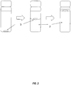
- FIG. 3 shows ice 2 and sorptive stir bar 3.
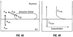
- FIG. 4B shows the concentration profile of the analyte near the ice-liquid interface.
- K solid an effective partition coefficient
- C A,SB , C A,solid , and C A,l represents the concentration of the analyte in the sorptive stirrer, solid, and liquid solution, respectively.
- the log K SB is between -0.7 and 4.0; more preferably between -0.6 and 3.0; most preferably between -0.5 and 2.5.
- K solid is generally on the order of 0.1 to 0.0001 (pk solid of 1 to 4) depending on the solvent, stir rate, solute concentration, and freeze rate. Without seeking to be limited to a particular theory, it is believed that because K solid decreases as the solute concentrations decreases, a K solid of approximately 0.01 is considered conservative for the analysis according to the present invention.
- the invention extracts at least 80% of the analyte, more preferably at least 85% of the analyte, more preferably at least 90% of the analyte for those analytes with a K SB greater than 15.
- FIG. 5A illustrates the behavior of an analyte (i.e., the fraction of analyte extracted into the sorptive stirrer) as the analyte undergoes the methods of the present invention. As shown in FIG.
- FIG. 5A indicates the fraction extracted into the sorptive stirrer as the K SB of the analyte increases. Using a K solid of 0.01, the fraction extracted rises to above 90% as the log K SB of the analyte increases to just over 1, whereas a log K SB > 3 is necessary to extract over 90% of the analyte under the same conditions.
- FIG. 5C shows that the present invention is advantageous for analysis over SBSE.
- Embodiments of the present invention are further defined in the following non-limiting Examples. It should be understood that these Examples, while indicating certain embodiments of the invention, are given by way of illustration only. From the above discussion and these Examples, one skilled in the art can ascertain the essential characteristics of this invention, and without departing from the spirit and scope thereof, can make various changes and modifications of the embodiments of the invention to adapt it to various usages and conditions. Thus, various modifications of the embodiments of the invention, in addition to those shown and described herein, will be apparent to those skilled in the art from the foregoing description. Such modifications are also intended to fall within the scope of the appended claims.
- FIG. 6 is a series of photographs showing the concentration of the methyl violet at various points during the test.
- the dye solution is visible prior to application of the methods of the invention.
- Figure 6B shows the dye visibly separated on top of the crystalline phase during of the method, where approximately 50% of the dye solution has been frozen.
- Figure 6C shows the dye solution visibly separated on top of the crystalline phase during the methods, where the dye has been concentrated and the majority of the water has been separated and frozen.
- DMTS dimethyltrisulfide
- BA benzaldehyde
- Aqueous samples 100 nM; 12.6 ppb for DMTS and 10.6 ppb for BA
- the results of both the present invention and SBSE were analyzed by GCMS.
- FIG. 7 indicates the results of the analysis based on peak area.
- the signals of both DMTS and BA were enhanced using the methods of the present invention.
- the present invention produced a concentration factor of three times and eight times for DMTS and BA, respectively, compared to SBSE. For example, FIG.
- FIG. 8 shows the comparative peaks for SBSE and the present invention.
- FIG. 9 indicates the concentration factors as a function of temperature for BA.
- FIG. 10 indicates that concentration factors decreased with the increase of stir speed.
- FIG. 11 illustrates the relationship between concentration and concentration factor.
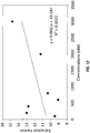
- FIG. 12 indicates there is little to no correlation between the concentration factor and the solution concentration.
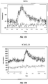
- the level of detection (LOD) for BA was also determined and is comparatively shown in FIGs. 13A and 13B .
- the LOD of BA was decreased five times using the methods of the present invention.
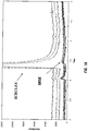
- FIG. 14 illustrates the lower limit of qualification for SBSE, while FIGs. 15A and 15B indicate the concentration factor at the lower limit of qualification for the present invention and SBSE. As shown, the lower limit of qualification for the present invention is much lower than that of SBSE. This is further shown in FIG. 15B .
- the methods of the invention are capable of detection of solutes and much lower concentrations than existing methods.
- Benzyl alcohol was analyzed according to the methods and apparatus of the present invention. Results of the present invention are compared to results of SBSE as shown FIG. 16 . The limit of detection was also determined for both the present invention and SBSE for benzyl alcohol as shown in FIG. 17A and FIG. 17B , respectively.
- the LOD of benzyl alcohol extracted according to the methods of the present invention was approximately 40 nM as compared to 1 ⁇ M. Therefore, the LOD was decreased twenty-five times using the methods of the present invention.
- This Example further confirms that the methods of the invention are capable of detection of solutes and much lower concentrations than existing methods.
Landscapes
- Chemical & Material Sciences (AREA)
- Life Sciences & Earth Sciences (AREA)
- Analytical Chemistry (AREA)
- Health & Medical Sciences (AREA)
- Physics & Mathematics (AREA)
- Pathology (AREA)
- Biochemistry (AREA)
- General Health & Medical Sciences (AREA)
- General Physics & Mathematics (AREA)
- Immunology (AREA)
- Chemical Kinetics & Catalysis (AREA)
- Food Science & Technology (AREA)
- Medicinal Chemistry (AREA)
- Engineering & Computer Science (AREA)
- Crystallography & Structural Chemistry (AREA)
- Thermal Sciences (AREA)
- Hydrology & Water Resources (AREA)
- Sampling And Sample Adjustment (AREA)
Description
- The invention relates to selective trace and ultratrace analysis of analytes. In particular, this analysis is achieved by simultaneously freeze concentrating and extracting the analyte into a sorptive or by a sorptive material. Further, the methods and apparatus of the present invention can be useful in conducting ultratrace analysis for toxic chemicals that may be present in drinking water. Further, the methods and apparatus of the present invention can be useful in concentrating and isolating target chemicals of high value.
- Analytical chemistry is concerned with both identification and quantification of chemicals. Trace and ultratrace analysis is focused on miniscule quantities. Trace and ultratrace analysis can be important in many areas of analytical chemistry. For example, it can be useful in forensic analysis, quality control, and the analysis of toxins. Sample preparation, including preconcentration, is a key step for almost all analyses. Sample preparation and preconcentration, along with highly sophisticated instrumentation becomes increasingly important when trace and ultratrace detection of analytes is necessary. In addition to more historic sample preparation techniques such as liquid-liquid extraction and simple solvent evaporation, multiple techniques have been introduced over the past several decades to aid analysts in determined low concentrations of analytes such as solid-phase extraction (SPE), solid-phase microextraction (SPME), and stir bar sorptive extraction (SBSE). While the compatibility of each analyte with these techniques must be individually evaluated, these sample preparation techniques have generally produced decreased limits of detection, decreased analysis times, and decreased organic solvent use. Although current sample preparation techniques are excellent for analysis in the parts-per-billion (ppb; µg/L) and high parts-per-trillion (ppt; ng/L) range, ultratrace analysis is still very difficult for analytical chemists to achieve without arduous sample preparation and/or extremely sophisticated and expensive instrumentation. In some cases, even with the most sensitive instruments, analysis of a compound of interest at a desired concentration may still not be possible without concentrating large sample volumes (e.g., greater than 500 mL). Therefore a technique with the ability to more easily determine ultratrace concentrations of interest could be a foundational technique in the field of analytical sample preparation. Furthermore, such a technique would allow more applicable standards to be set of toxic compounds of interest and help ensure human health, to include safe drinking water standards.
- The ability to analyze contaminants at ultratrace concentrations is a critically important, but currently challenging, aspect of ensuring safe drinking water. The EPA Maximum Contaminant Level Goal (MCLG) is zero for several compounds, but the enforceable contaminant level, called the Maximum Contaminant Level (MCL), is set, in part, according to the ability of laboratories to measure accurately and consistently the level of the contaminant with available analytical methods. This typically limits MCLs to the parts-per-billion or microgram per liter range. The ability to more easily analyze compounds at extremely low concentrations would be a tremendous achievement in the analytical chemistry field and would have a broad impact, including, for example, in assisting with the provision of safe drinking water. The present invention allows analysis of select compounds in liquid solution at much lower limits-of-detection (LODs) than currently available. In the absence of the present invention, performing trace and ultratrace analysis of certain classes of solutes in drinking water samples, and ultimately ensuring safe drinking water, will remain difficult and force undesirable analytical alternatives (e.g., expensive instrumentation and/or concentrating large sample volumes).
- In the past several decades, multiple sample preparation techniques have been introduced to extend the reach of analytical methods into the low parts-per-billion, parts-per-trillion, and even parts-per-quadrillion range by purifying and pre-concentrating target analytes and using sophisticated instrumentation. Sample preparation techniques such as SPE, SPME, and SBSE can extend the concentration range for analysis to ultratrace levels. Although these sample preparation techniques may work well for certain analytes, each has disadvantages, such as limited preconcentration factors among others. For example, SBSE has limitations on the type of analytes for which the procedure can be used due to the limited number of sorbent phases available. Further, SPE typically has a need for a drying step prior to analysis.
- Further, although freeze concentration (FC) has received little attention the field of analytical chemistry, it has been used for decades to concentrate solutes from solutions and has found common application in the food industry for creating frozen concentrates of fruit juices and ice beer. As the name implies, FC is a technique for concentrating solutes by freezing a solution. Solutes are concentrated based on the direct relationship between freezing point depression and solute molality. If a solution is slowly frozen, local regions of solvent with a low solute concentration are frozen first and the solution left behind is more concentrated. Although higher solute concentrations decrease the freezing point of a solution, the rate of freezing is generally too fast to freeze out pure solvent when high solute concentrations are present. Therefore, the solution is typically stirred vigorously during FC to counteract incorporation of the solute into the frozen solvent. However, FC is indiscriminant as to the solutes that are concentrated.
- Accordingly, it is an objective of the claimed invention to develop a method and apparatus of selective preconcentration and isolation which can discriminate particular compounds. The method and apparatus may be used to facilitate trace and ultratrace analysis or isolation of high value compounds.
- A further object of the invention is to allow the trace and ultratrace analysis of toxic chemicals which currently cannot be easily analyzed at the desired concentrations (e.g., maximum contaminant levels; MCLs).
-
US 2002/098594 discloses a method for solid-phase microextraction and analysis of substances in a carrier fluid, in which a collector is brought into contact with the stirred fluid containing the substances for a sufficient time and is then subjected to a solid-phase extraction directed at at least one substance adhering to the collector, and desorbed substances are transported for analysis by means of a carrier gas, in which the carrier fluid containing the substances is stirred in a receptacle of a magnetic stirrer by means of a coated magnetic stirring element as the collector, and/or the carrier fluid is made to move intimately relative to the collector by means of ultrasound, and then the stirring element is placed in a solid-phase extraction device. - The invention provides apparatuses and methods for performing trace and ultratrace analysis by simultaneously freeze concentrating and extracting the analyte into or by a sorptive material. The analyte can be extracted from the sorptive material, identified by qualitative analysis, and/or quantified by quantitative analysis. In a preferred embodiment, the apparatuses and methods of the invention can be applied to the monitoring of drinking water.
- An advantage of the invention is that it provides apparatuses and methods that can be applied to very low concentrations of analyte in a liquid medium.
- While multiple embodiments are disclosed, still other embodiments of the present invention will become apparent to those skilled in the art from the following detailed description, which shows and describes illustrative embodiments of the invention. Accordingly, the drawings and detailed description are to be regarded as illustrative in nature and not restrictive.
-
- FIG. 1
- illustrates an apparatus of the present invention including a u-shaped bracket.
- FIG. 2
- illustrates an apparatus of the present invention including a magnetic stir plate.
- FIG. 3
- illustrates the method and the different stages of concentration as they occur during the course of the method.
- FIG. 4A
- shows that there are three material phases with which the analyte while associated in the present invention: liquid, solid, and stir bar.
FIG. 4B shows the concentration profile of the analyte near the ice-liquid interface. - FIG. 5A
- illustrates the behavior of an analyte (i.e., the fraction of analyte extracted into the stir bar) as the analyte undergoes the methods of the present invention.
FIG. 5B indicates the fraction extracted into the stir bar as the KSB of the analyte increases.FIG. 5C shows that the present invention is advantageous for analysis over SBSE. - FIGS. 6A-C
- are photographs showing the concentration of the methyl violet at various points during Example 1.
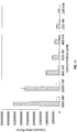
- FIG. 7
- indicates the results of the analysis based on peak area that the signs of both chemicals where enhanced by using the methods of the present invention.
- FIG. 8
- shows the comparative peaks for SBSE and the present invention.
- FIG. 9
- indicates the concentration factors as a function of temperature for benzaldehyde.
- FIG. 10
- indicates that concentration factors decreased with the increase of stir speed.
- FIG. 11
- illustrates the relationship between concentration and concentration factor.
- FIG. 12
- indicates there is little to no correlation between the concentration factor and the solution concentration.
- FIG. 13A
- indicates the level of detection for benzaldehyde using the present invention while
FIG. 13B indicates the level of detection for benzaldehyde using SBSE. - FIG. 14
- illustrates the lower limit of qualification for SBSE.
- FIG. 15A
- indicates the concentration factor at the lower limit of qualification for the present invention and SBSE.
FIG. 15B shows that the lower limit of qualification of benzaldehyde for the present invention as compared to that of SBSE. - FIG. 16
- illustrates the analysis of benzyl alcohol using the present invention as compared to SBSE.
- FIG. 17A
- shows the limit of detection of benzyl alcohol using the present invention while
FIG. 17B shows the limit of detection of benzyl alcohol using SBSE. - Various embodiments of the present invention will be described in detail with reference to the drawings, wherein like reference numerals represent like parts throughout the several views. Reference to various embodiments does not limit the scope of the invention.
- Figures represented herein are not limitations to the various embodiments according to the invention and are presented for exemplary illustration of the invention.
- The present invention relates selective concentration of solutes for trace and ultratrace analysis. The methods and apparatus of the present invention have many advantages over existing trace and ultratrace analyses. For example, the present invention increases the concentration factor (i.e., the ratio of the concentration of analyte in the prepared sample to that in the original solution) of selected solutes over existing sample preparation methods.
- The embodiments of this invention are not limited to particular apparatuses for performing the methods of invention, which can vary and are understood by skilled artisans. It is further to be understood that all terminology used herein is for the purpose of describing particular embodiments. For example, as used in this specification and the appended claims, the singular forms "a," "an" and "the" can include plural referents unless the content clearly indicates otherwise. Further, all units, prefixes, and symbols may be denoted in its SI accepted form. Numeric ranges recited within the specification are inclusive of the numbers defining the range and include each integer within the defined range (e.g., 1 to 5 includes 1, 1.5, 2, 2.75, 3, 3.80, 4, and 5).
- So that the present invention may be more readily understood, certain terms are first defined. Unless defined otherwise, all technical and scientific terms used herein have the same meaning as commonly understood by one of ordinary skill in the art to which embodiments of the invention pertain. Many methods and materials similar, modified, or equivalent to those described herein can be used in the practice of the embodiments of the present invention without undue experimentation, the preferred materials and methods are described herein. In describing and claiming the embodiments of the present invention, the following terminology will be used in accordance with the definitions set out below.
- The term "analyte," as used herein, is a substance whose chemical constitutes are being identified and measured. "Solute," as used herein, is the minor component in a solution, dissolved in the solvent. Further, analyte may be used interchangeably with solute.
- The term "ICELES" as used herein, is an abbreviation for "ice concentration extraction linked with extractive stirring," which can be used to describe an exemplary method of the invention.
- The term "Ksolid," as used herein, refers to the effective partitioning constant between the solid and the liquid phase. Additionally, log Ksolid is defined as the log value of Ksolid.
- The term "Kow," as used herein, refers to the octanol-water partition coefficient, or the ratio of the solubility of a compound in octanol to its solubility in water. The higher the Kow, the more non-polar the compound. Additionally, log Kow is defined as the log value of Kow.
- The term "KSB," as used herein, refers to the effective partitioning coefficient between the stir bar and the liquid phase. Additionally, log Ksb is defined as the log value of Ksb.
- The term "limit of blank" or "LOB," as used herein is highest apparent analyte concentration expected to be found when replicates of a blank sample containing no analyte are tested.
- The term "limit of detection" of "LOD," as used herein is the lowest analyte concentration likely to be reliably distinguished from the LOB and at which detection is feasible.
- The term "lower limit of quantification" or "LLOQ," as used herein, is the lowest concentration at which the analyte can not only be reliably detected but at which some predefined goals for bias and imprecision are met.
- The term "parts-per-billion" or "ppb," as used herein is one part per 1,000,000,000 parts and corresponds to 1 µg/L with a density of water of 1.0 g/mL. Similarly, "parts-per-trillion" or "ppt," as used herein in one part per 1,000,000,000,000 and corresponds to 1 ng/L with a density of water of 1.0 g/mL.
- The term "weight percent," "wt-%," "percent by weight," "% by weight," and variations thereof, as used herein, refer to the concentration of a substance as the weight of that substance divided by the total weight of the composition and multiplied by 100. It is understood that, as used here, "percent," "%," and the like are intended to be synonymous with "weight percent," "wt-%," etc.
- Embodiments of the invention include methods and apparatuses for selective trace and ultratrace analysis. The methods and apparatuses according to the invention are capable of concentrating analytes from a sample for analysis at trace and ultratrace levels. The invention overcomes the shortfalls of conventional trace and ultratrace analysis techniques by reducing the sample volume while permitting trace and ultratrace analysis. Additionally, the invention is capable of targeting desired analytes.
- The apparatuses for performing trace and ultratrace analysis includes a a sample container, sorptive stirrer, and cooling source. In some aspects the apparatus further includes a magnet. In some aspects the apparatus further consists of a stir plate. In some aspects the apparatus may include an overhead stirrer. In some aspects, the apparatus may optionally include at least one measurement device. In some aspects the apparatus may optionally include a control system.
- The apparatus includes a container in which the sample to be analyzed is placed. Any suitable container for holding the sample that will permit the rotation of a sorptive stirrer can be used including, for example, but not limited to, a beaker, flask, test tube, or vial. The container can be supported on its own or by any suitable support, including, for example a test tube or vial holder, a clamp, a bracket, or an arm.
- The apparatuses and methods of the invention employ a sorptive stirrer comprising a sorptive material. The analyte can be absorbed into or adsorbed by the sorptive material. The sorptive material can be a coating, a jacket, or a layer on a stirrer. In some embodiments the sorptive stirrer can have a layer, jacket, or coating that is chemically-inert, or sufficiently inert so as not to impact the analyte's adsorption by or absorption into the sorptive material. A preferred chemically-inert coating, layer, or jacket is glass. Other suitable chemically-inert coating, layers, or jackets can be used.
- In some embodiments of the invention, the sorptive stirrer is a magnetic stir bar with a sorptive jacket or sorptive layer is contained within the vial. In some embodiments the sorptive stirrer is an overhead stirrer with sorptive jacket or sorptive layer can be used. Preferably, the magnetic stir bar with sorptive jacket/layer is a magnetic bar contained within a sealed glass container which is fitted or coated with a sorptive layer. Preferably, an overhead stirrer with sorptive jacket/layer is an overhead stirrer with a stir rod that can be inserted into the sample container which is coated or fitted with sorptive material such that the sorptive material is immersed in the sample within the container.
- The sorptive material can be selected to target specific analytes. In an embodiment of the invention, the sorptive material can include, but is not limited to, polydimethylsiloxane, polydimethylsiloxane/ethylene glycol copolymer, molecularly imprinted polymers, ion exchange material, or other common sorbent phases. In a preferred embodiment, the sorptive layer is polydimethylsiloxane.
- The apparatus also includes one or more magnets for stirring the stir bar. A magnet can be part of a stir plate, U-shaped bracket having magnets in each arm, or donut-shaped ring having magnets housed in the ring on opposite sides. Further, a magnetic field may be generated by electric current through an appropriate electric circuit. In embodiments using a U-shaped bracket, the vial and optionally the cooling source can be between the bracket arms and as the bracket rotates it causes the stir bar to spin. In embodiments using a donut-shaped ring, the vial is housed in the hole in the ring and as the ring is rotated, it causes the stir bar to spin. In embodiments with electric current generated magnetic fields, the vial is housed such that the magnetic fields rotate the stir bar within the container.
- The apparatus includes a cooling source in order to freeze the sample. A cold bath is preferred cooling source. However, any suitable cooling source can be used to freeze the sample, including for example use of a jacketed beaker (i.e. a double-walled beaker with inlet and outlet to allow coolant flow), coolant, cooled air system, thermoelectric device, helium, or nitrogen system.
- In some embodiments of the invention, the container is held by a holder that is connected to a stepper motor that lowers the container within the holder into the cooling source, such as a cold bath. The stepper motor is directed by a control system to maintain a given rate of descent of the container into the cooling source.
- In some embodiments of the invention, the apparatus may include at least one measurement device or a plurality of measurement devices. Such measurement devices are those suitable to measure one or more variables of the system such as temperature, speed, pH, and combinations thereof. Such a measurement device can measure the cooling source, the container, magnetic field (e.g., strength and/or position), spectroscopic behavior of the analyte, the sorptive stirrer, etc. For example, in an embodiment of the invention, temperature is monitored at various points in the apparatus to ensure consistent freezing of the sample. In further aspects of the invention, the apparatus comprises an optional controller or software platform. The software platform provides a user or system to select speed and temperature of freezing as well as speed of stirring. As a result, use of the apparatus provides significant use flexibility to concentrate a variety of analytes for particular user-identified purposes. For example, the controller or control software for operation of the apparatus may permit a user or system to select both the temperature of the system and the speed of stirring. In a further aspect, the control software may determine the timing of the lowering of the vial and the overall concentration process. In a still further aspect of the invention, the control system includes the above described measurement devices.
- In some embodiments of the invention, the entire apparatus or select components of the apparatus may be contained in a cooled container to control the temperature of the apparatus and sample.
- According to an embodiment of the invention shown in the exemplary and non-limiting
FIG. 1 , the sample container containing the sample and the sorptive stirrer is lowered into a cooling source which is surrounded by a magnet. Further the sample container is held by a sample holder which can be lowered incrementally by a motor.FIG. 1 shows avial 1 which is slowly lowered intocold bath 5, abracket 7 with magnets on either side, and astepper motor 11. - According to an embodiment of the invention shown in the exemplary and non-limiting
FIG. 2 , the sample container containing the sample and the sorptive stirrer is lowered into a cooling source, which is located on top of a magnetic stir plate.FIG. 2 shows asorptive stir bar 3, acold bath 5, achiller 6, astir plate 8, andMeOH 9. - The methods according to the present invention for conducting trace and ultratrace analysis of an analyte or concentrating a solute in a solvent can include providing an analyte for analysis, stirring the analyte and simultaneously cooling the analyte. The simultaneous cooling and stirring of the composition allows the solvent to freeze and solutes to become concentrated. According to the present invention, the analyte contained in a liquid medium is placed in the container along with the sorptive stirrer compatible with the analyte(s) of interest. Sorptive stirrer comprises a sorptive material. The analyte can be absorbed into or adsorbed by the sorptive material. In some embodiments, a step can be added to coat the stirrer with the sorptive material.
- As the container is lowered into the cooling source, or alternatively as the solvent reaches its freezing point, the solvent begins to crystalize on the bottom of the container in an upward direction (relative to the bottom of the container) and the sorptive stirrer continues to stir on top of the frozen solvent. Once the solvent is completely frozen, the sorptive stirrer is removed from the top of the frozen solvent and can be analyzed by an analytical technique, such as gas-chromatography mass-spectroscopy (GCMS), thermal desorption GCMS, liquid chromatography, fluorometry, spectroscopy, or any other analytical technique. The analysis can include extraction of the analyte from the sorptive material. Preferably the extraction of the analyte is into a liquid solvent or into the gas phase such that it is amenable for follow-on analysis. Subsequent analytical techniques can be selected and applied to the analyte in a liquid, solid, and/or gas phase.
- According to an embodiment of the invention shown in the exemplary and non-limiting
FIG. 3 , the method and the different stages of concentration as they occur during the course of the method are shown. The sample container containing the liquid phase sample and the sorptive stirrer is cooled so that the crystalline phase forms during the method.FIG. 3 showsice 2 andsorptive stir bar 3. - While an understanding of the mechanism is not necessary to practice the present invention and while the present invention is not limited to any particular mechanism of action, it is contemplated that, in some embodiments, there are three material phases to consider: liquid, solid, and sorptive stirrer as shown in
FIG. 4A . Some among of analyte - (A) will be associated with each of these phases as shown in
FIG. 4A. FIG. 4B shows the concentration profile of the analyte near the ice-liquid interface. Even though the analyte contained within the solid phase is not truly in equilibrium with other material phases in the system, the distribution of the analyte between the solid and liquid solution is described by an effective partition coefficient, Ksolid. According the present invention, the effectiveness of the method for purposes of analytical sample preparation is indicated by the fraction of analyte extracted (fextr,SB). For the present invention, the extracted analyte is analyzed from the sorptive stirrer.Equation 1 defines the fraction of the analyte extracted:
Equation 1 can be written as Equation 2:
Equation 2 can be simplified to Equation 3:
- During the methods of the present invention, the volume of solid (Vsolid) increases and the liquid volume (Vl) decreases until Vl becomes negligible. Therefore, the equation describing the fraction of the analyte extracted into the stir bar becomes Equation 4:

- According to some embodiments of the invention, the log KSB is between -0.7 and 4.0; more preferably between -0.6 and 3.0; most preferably between -0.5 and 2.5. According to a further embodiment of the invention, for water as a solvent, Ksolid is generally on the order of 0.1 to 0.0001 (pksolid of 1 to 4) depending on the solvent, stir rate, solute concentration, and freeze rate. Without seeking to be limited to a particular theory, it is believed that because Ksolid decreases as the solute concentrations decreases, a Ksolid of approximately 0.01 is considered conservative for the analysis according to the present invention. Thus, preferably the invention extracts at least 80% of the analyte, more preferably at least 85% of the analyte, more preferably at least 90% of the analyte for those analytes with a KSB greater than 15. By comparison, this presents a significant advantage over the conventional methods of stir bar sorptive extraction.
FIG. 5A illustrates the behavior of an analyte (i.e., the fraction of analyte extracted into the sorptive stirrer) as the analyte undergoes the methods of the present invention. As shown inFIG. 5A , for analytes with smaller KSB, concentration into the stir bar is more pronounced over the last few mL of freezing and analytes with KSBs that are typically too low for stir bar sorptive extraction are able to be extracted into the sorptive stirrer at over 80%.FIG. 5B indicates the fraction extracted into the sorptive stirrer as the KSB of the analyte increases. Using a Ksolid of 0.01, the fraction extracted rises to above 90% as the log KSB of the analyte increases to just over 1, whereas a log KSB > 3 is necessary to extract over 90% of the analyte under the same conditions.FIG. 5C shows that the present invention is advantageous for analysis over SBSE. - Embodiments of the present invention are further defined in the following non-limiting Examples. It should be understood that these Examples, while indicating certain embodiments of the invention, are given by way of illustration only. From the above discussion and these Examples, one skilled in the art can ascertain the essential characteristics of this invention, and without departing from the spirit and scope thereof, can make various changes and modifications of the embodiments of the invention to adapt it to various usages and conditions. Thus, various modifications of the embodiments of the invention, in addition to those shown and described herein, will be apparent to those skilled in the art from the foregoing description. Such modifications are also intended to fall within the scope of the appended claims.
- A dye solution was tested according to the methods and apparatus of the invention. The aqueous dye solution in the amount of 10 mL was placed in a vial with a sorptive stir bar. The vial was then placed into a jacketed beaker (i.e. a double-walled beaker with inlet and outlet to allow coolant flow). The concentration of methyl violet into the stir bar was visually confirmed.
FIG. 6 is a series of photographs showing the concentration of the methyl violet at various points during the test. InFigure 6A , the dye solution is visible prior to application of the methods of the invention.Figure 6B shows the dye visibly separated on top of the crystalline phase during of the method, where approximately 50% of the dye solution has been frozen.Figure 6C shows the dye solution visibly separated on top of the crystalline phase during the methods, where the dye has been concentrated and the majority of the water has been separated and frozen. - Two molecules: dimethyltrisulfide (DMTS; log Kow = 1.87) and benzaldehyde (BA; log Kow = 1.48) were concentrated according to the methods and apparatus of the present invention. Aqueous samples (100 nM; 12.6 ppb for DMTS and 10.6 ppb for BA) were prepared by the methods of the present invention and also by SBSE. The results of both the present invention and SBSE were analyzed by GCMS.
FIG. 7 indicates the results of the analysis based on peak area. The signals of both DMTS and BA were enhanced using the methods of the present invention. The present invention produced a concentration factor of three times and eight times for DMTS and BA, respectively, compared to SBSE. For example,FIG. 8 shows the comparative peaks for SBSE and the present invention.FIG. 9 indicates the concentration factors as a function of temperature for BA.FIG. 10 indicates that concentration factors decreased with the increase of stir speed.FIG. 11 illustrates the relationship between concentration and concentration factor.FIG. 12 indicates there is little to no correlation between the concentration factor and the solution concentration. The level of detection (LOD) for BA was also determined and is comparatively shown inFIGs. 13A and 13B . The LOD of BA was decreased five times using the methods of the present invention. FurtherFIG. 14 illustrates the lower limit of qualification for SBSE, whileFIGs. 15A and 15B indicate the concentration factor at the lower limit of qualification for the present invention and SBSE. As shown, the lower limit of qualification for the present invention is much lower than that of SBSE. This is further shown inFIG. 15B . Thus, the methods of the invention are capable of detection of solutes and much lower concentrations than existing methods. - Benzyl alcohol was analyzed according to the methods and apparatus of the present invention. Results of the present invention are compared to results of SBSE as shown
FIG. 16 . The limit of detection was also determined for both the present invention and SBSE for benzyl alcohol as shown inFIG. 17A and FIG. 17B , respectively. The LOD of benzyl alcohol extracted according to the methods of the present invention was approximately 40 nM as compared to 1 µM. Therefore, the LOD was decreased twenty-five times using the methods of the present invention. This Example further confirms that the methods of the invention are capable of detection of solutes and much lower concentrations than existing methods. - For the invention being thus described, it will be obvious that the same may be varied in many ways. Such variations are not to be regarded as a departure from the spirit and scope of the inventions and all such modifications are intended to be included within the scope of the following claims.
- The above specification provides a description of the methods and apparatus of the present invention. Since many embodiments can be made without departing from the spirit and scope of the invention, the invention resides in the claims.
Claims (15)
- An apparatus for extracting analytes from a liquid medium, comprising:a sample container, anda sorptive stirrer comprising a sorptive material;wherein said liquid medium is placed in said sample container; andwherein saidsorptive stirrer is placed in said sample container;characterized in that the apparatus further comprises
a cooling source for freezing the liquid medium from the bottom of the sample container in an upward direction, wherein said sample container is placed in or on said cooling source, and wherein the apparatus is adapted to perform simultaneously freeze concentrating and extracting the analyte into or by the sorptive material. - The apparatus according to claim 1, wherein, in a first alternative, said sorptive stirrer is a magnetic stir bar or overhead stirrer; and wherein said sorptive stirrer optionally comprises a chemically-inert coating, jacket, or layer, or:
wherein, in a second alternative, said sorptive stirrer is a sorptive magnetic stir bar; and wherein the apparatus further comprises a magnetic stir plate, a rotating magnetic U-shaped bracket, a rotating magnetic donut-shaped component or an electromagnetic field generator that generates a rotating magnetic field around said sample container. - The apparatus according to claim 1, further comprising a stepper motor, preferably wherein said stepper motor lowers said container containing said liquid medium into said cooling source in order to facilitate the freezing of said liquid medium.
- The apparatus according to claim 1, further comprising at least one measurement device, measuring one or more apparatus variables, preferably wherein said measurement device measures temperature, magnetic field, spectroscopic behavior of the analyte, speed of the sample container movement, stir speed, or combinations thereof.
- The apparatus according to claim 1, further comprising a control software for operating said apparatus to perform ultratrace analysis according to a user- or system selected analyte, wherein said control software determines the temperature, speed of the sample container movement, speed of the stir bar, magnetic field strength and/or position, spectroscopic parameters, and/or combinations thereof.
- A method of extracting an analyte from a liquid medium, comprising:stirring a liquid medium containing an analyte in a sample container with a sorptive stirrer comprising a sorptive material; characterized in that the method further comprisescooling the sample container while the analyte is being stirred so that the liquid medium freezes from the bottom of the sample container in an upward direction,and the analyte is concentrated and absorbed into or adsorbed by the sorptive material, wherein said cooling is done by a cooling source, and wherein freeze concentrating and extracting the analyte into or by the sorptive material is performed simultaneously.
- The method of claim 6, wherein said sorptive stirrer is an overhead stirrer or a magnetic sorptive stir bar rotated by a magnetic stir plate, magnetic U-shaped bracket, donut-shaped magnet, or electromagnetic field generator; and wherein said sorptive stirrer optionally comprises a chemically-inert coating, jacket, or layer, preferably wherein said magnetic U-shaped bracket or donut-shaped magnet rotates around said cooling source.
- The method of claim 6, further comprising extracting the analyte from the sorptive material after the cooling step.
- The method of claim 6, wherein said stirring step further comprises incrementally lowering the sample container into the cooling source.
- The method of claim 6, further comprising a step of measuring variables of the method, wherein the measuring step measures temperature, speed of the sample container movement, speed of the sorptive stirrer, and combinations thereof.
- The method of claim 6, further comprising a step of controlling the method using control software.
- A method of extracting a solute from water, comprising:stirring water containing an analyte in a sample container with a sorptive stirrer comprising a sorptive material; andcooling the sample container while the water is being stirred so the water freezes andthe analyte is concentrated and absorbed into the sorptive stir bar.
- The method of claim 12, further comprising extracting the analyte from the sorptive material.
- The method of claim 13 further comprising identifying and/or quantifying the analyte with an analytical technique including one or more of the following: gas-chromatography and mass-spectroscopy (GCMS), thermal desorption GCMS, liquid chromatography, fluorometry, or spectroscopy.
- The method of claim 14, further comprising quantifying the analyte in an amount of nanograms to femtograms.
Applications Claiming Priority (1)
| Application Number | Priority Date | Filing Date | Title |
|---|---|---|---|
| US14/928,694 US10139317B2 (en) | 2015-10-30 | 2015-10-30 | Methods and apparatuses for trace and ultratrace analysis |
Publications (2)
| Publication Number | Publication Date |
|---|---|
| EP3163285A1 EP3163285A1 (en) | 2017-05-03 |
| EP3163285B1 true EP3163285B1 (en) | 2020-09-02 |
Family
ID=57354092
Family Applications (1)
| Application Number | Title | Priority Date | Filing Date |
|---|---|---|---|
| EP16195607.3A Active EP3163285B1 (en) | 2015-10-30 | 2016-10-25 | Methods and apparatuses for trace and ultratrace analysis |
Country Status (3)
| Country | Link |
|---|---|
| US (1) | US10139317B2 (en) |
| EP (1) | EP3163285B1 (en) |
| JP (1) | JP6480396B2 (en) |
Families Citing this family (5)
| Publication number | Priority date | Publication date | Assignee | Title |
|---|---|---|---|---|
| TWI598150B (en) * | 2016-09-30 | 2017-09-11 | 財團法人工業技術研究院 | Grinding machine and slightly gyration device |
| WO2019084410A1 (en) * | 2017-10-26 | 2019-05-02 | Repligen Corporation | Micro alternating tangential flow perfusion filter, process vessel, and methods of use thereof |
| CN108404791B (en) * | 2018-04-08 | 2020-07-17 | 常州信息职业技术学院 | Stirring mechanism of chemical container |
| CN109407571B (en) * | 2018-09-03 | 2021-05-28 | 安徽伟迈信息技术有限公司 | A sewage monitoring system |
| US20260000911A1 (en) * | 2024-07-01 | 2026-01-01 | Boston Scientific Scimed, Inc. | Cancer therapy delivery system and components thereof |
Family Cites Families (13)
| Publication number | Priority date | Publication date | Assignee | Title |
|---|---|---|---|---|
| GB1570944A (en) | 1977-03-19 | 1980-07-09 | Douwe Egberts Tabaksfab | Process for the concentration of aqueous solutions |
| ATE35381T1 (en) * | 1985-03-25 | 1988-07-15 | Duphar Int Res | PLANT TO CONCENTRATE SOLUTIONS. |
| JPS63147503A (en) * | 1986-12-12 | 1988-06-20 | Kinki Univ | Method for concentrating component in animal and plant |
| JPH0790161B2 (en) | 1993-06-28 | 1995-10-04 | 株式会社サイニクス | Cooling heating stirring device |
| JP4114893B2 (en) | 1998-02-03 | 2008-07-09 | カゴメ株式会社 | Forward freeze concentration method |
| JP4070326B2 (en) | 1998-10-20 | 2008-04-02 | 慎一 秋山 | Non-contact stirring device |
| US6815216B2 (en) | 1999-03-26 | 2004-11-09 | Gerstel Systemtechnik Gmbh & Co. Kg | Method for solid-phase microextraction and analysis, and a collector for this method |
| DE19933017A1 (en) * | 1999-03-26 | 2001-01-18 | Gerstel Systemtechnik Gmbh | Solid phase micro-extrusion and analysis procedures |
| JP2001009254A (en) | 1999-06-29 | 2001-01-16 | Shimadzu Corp | Mixer |
| EP1252495A2 (en) | 2000-02-02 | 2002-10-30 | PAWLISZYN, Janusz B. | Analytical devices based on diffusion boundary layer calibration and quantitative sorption |
| JP2001286745A (en) | 2000-04-05 | 2001-10-16 | Fuji Photo Film Co Ltd | Method for mixing liquid or solution and device therefor |
| JP2006070084A (en) * | 2004-08-31 | 2006-03-16 | Daikin Ind Ltd | Method for producing fluorinated polymer concentrated aqueous dispersion and method for concentrating surfactant aqueous liquid |
| AU2014312814B2 (en) * | 2013-08-29 | 2018-01-25 | Meiji Co., Ltd. | Production method for concentrated product using membrane-concentration method and freeze-concentration method |
-
2015
- 2015-10-30 US US14/928,694 patent/US10139317B2/en not_active Expired - Fee Related
-
2016
- 2016-10-25 EP EP16195607.3A patent/EP3163285B1/en active Active
- 2016-10-28 JP JP2016211360A patent/JP6480396B2/en not_active Expired - Fee Related
Non-Patent Citations (1)
| Title |
|---|
| None * |
Also Published As
| Publication number | Publication date |
|---|---|
| EP3163285A1 (en) | 2017-05-03 |
| US10139317B2 (en) | 2018-11-27 |
| US20170122845A1 (en) | 2017-05-04 |
| JP2017083449A (en) | 2017-05-18 |
| JP6480396B2 (en) | 2019-03-06 |
Similar Documents
| Publication | Publication Date | Title |
|---|---|---|
| US10139317B2 (en) | Methods and apparatuses for trace and ultratrace analysis | |
| Qin et al. | Comparison of thin-film microextraction and stir bar sorptive extraction for the analysis of polycyclic aromatic hydrocarbons in aqueous samples with controlled agitation conditions | |
| Wardencki et al. | Trends in solventless sample preparation techniques for environmental analysis | |
| Bagheri et al. | Immersed solvent microextraction of phenol and chlorophenols from water samples followed by gas chromatography–mass spectrometry | |
| Kokosa et al. | Solvent microextraction: theory and practice | |
| Theis et al. | Headspace solvent microextraction | |
| Nerın et al. | Determination of bisphenol-type contaminants from food packaging materials in aqueous foods by solid-phase microextraction–high-performance liquid chromatography | |
| Leong et al. | Dispersive liquid–liquid microextraction method based on solidification of floating organic drop combined with gas chromatography with electron-capture or mass spectrometry detection | |
| Dong et al. | Simultaneous determination of sorbic and benzoic acids in food dressing by headspace solid-phase microextraction and gas chromatography | |
| Dong et al. | Headspace solid-phase microextraction applied to the simultaneous determination of sorbic and benzoic acids in beverages | |
| Henriksen et al. | Analysis of acidic pesticides using in situ derivatization with alkylchloroformate and solid-phase microextraction (SPME) for GC–MS | |
| Avino et al. | New protocol based on high-volume sampling followed by DLLME-GC-IT/MS for determining PAHs at ultra-trace levels in surface water samples | |
| Ghasemi et al. | Headspace hollow fiber protected liquid-phase microextraction combined with gas chromatography–mass spectroscopy for speciation and determination of volatile organic compounds of selenium in environmental and biological samples | |
| Chen et al. | Solid-phase microextraction with Whatman 1PS paper and direct room-temperature solid-matrix luminescence analysis | |
| O’Brien et al. | Determination of deployment specific chemical uptake rates for SDB-RPD Empore disk using a passive flow monitor (PFM) | |
| Fashi et al. | Solvent-stir bar microextraction system using pure tris-(2-ethylhexyl) phosphate as supported liquid membrane: a new and efficient design for the extraction of malondialdehyde from biological fluids | |
| Pawliszyn | Quantitative aspects of SPME | |
| Soria et al. | Headspace techniques for volatile sampling | |
| Feng et al. | Determination of trace polychlorinated biphenyls and organochlorine pesticides in water samples through large‐volume stir bar sorptive extraction method with thermal desorption gas chromatography | |
| Bagheri et al. | Trace determination of free formaldehyde in DTP and DT vaccines and diphtheria–tetanus antigen by single drop microextraction and gas chromatography–mass spectrometry | |
| Olariu et al. | Sample preparation for trace analysis by chromatographic methods | |
| Ridgway et al. | An alternative method for analysis of food taints using stir bar sorptive extraction | |
| Salleh et al. | An approach to solventless sample preparation procedure for pesticides analysis using solid phase microextraction/supercritical fluid extraction technique | |
| Wuilloud et al. | Determination of iodinated phenol species at parts-per-trillion concentration levels in different water samples by solid-phase microextraction/offline GC-ICP-MS | |
| Fathi et al. | Development of a hollow fiber–liquid phase microextraction method using tissue culture oil for the extraction of free metoprolol from plasma samples |
Legal Events
| Date | Code | Title | Description |
|---|---|---|---|
| PUAI | Public reference made under article 153(3) epc to a published international application that has entered the european phase |
Free format text: ORIGINAL CODE: 0009012 |
|
| STAA | Information on the status of an ep patent application or granted ep patent |
Free format text: STATUS: REQUEST FOR EXAMINATION WAS MADE |
|
| 17P | Request for examination filed |
Effective date: 20161109 |
|
| AK | Designated contracting states |
Kind code of ref document: A1 Designated state(s): AL AT BE BG CH CY CZ DE DK EE ES FI FR GB GR HR HU IE IS IT LI LT LU LV MC MK MT NL NO PL PT RO RS SE SI SK SM TR |
|
| AX | Request for extension of the european patent |
Extension state: BA ME |
|
| RBV | Designated contracting states (corrected) |
Designated state(s): AL AT BE BG CH CY CZ DE DK EE ES FI FR GB GR HR HU IE IS IT LI LT LU LV MC MK MT NL NO PL PT RO RS SE SI SK SM TR |
|
| STAA | Information on the status of an ep patent application or granted ep patent |
Free format text: STATUS: EXAMINATION IS IN PROGRESS |
|
| 17Q | First examination report despatched |
Effective date: 20190823 |
|
| GRAP | Despatch of communication of intention to grant a patent |
Free format text: ORIGINAL CODE: EPIDOSNIGR1 |
|
| STAA | Information on the status of an ep patent application or granted ep patent |
Free format text: STATUS: GRANT OF PATENT IS INTENDED |
|
| RIC1 | Information provided on ipc code assigned before grant |
Ipc: B01D 9/04 20060101ALI20200305BHEP Ipc: G01N 1/28 20060101ALN20200305BHEP Ipc: G01N 33/18 20060101ALI20200305BHEP Ipc: G01N 1/40 20060101AFI20200305BHEP Ipc: G01N 1/42 20060101ALI20200305BHEP Ipc: G01N 1/38 20060101ALN20200305BHEP Ipc: B01F 13/08 20060101ALI20200305BHEP |
|
| RIC1 | Information provided on ipc code assigned before grant |
Ipc: B01F 13/08 20060101ALI20200310BHEP Ipc: G01N 1/28 20060101ALN20200310BHEP Ipc: G01N 1/42 20060101ALI20200310BHEP Ipc: G01N 1/40 20060101AFI20200310BHEP Ipc: G01N 33/18 20060101ALI20200310BHEP Ipc: G01N 1/38 20060101ALN20200310BHEP Ipc: B01D 9/04 20060101ALI20200310BHEP |
|
| INTG | Intention to grant announced |
Effective date: 20200325 |
|
| GRAS | Grant fee paid |
Free format text: ORIGINAL CODE: EPIDOSNIGR3 |
|
| GRAA | (expected) grant |
Free format text: ORIGINAL CODE: 0009210 |
|
| STAA | Information on the status of an ep patent application or granted ep patent |
Free format text: STATUS: THE PATENT HAS BEEN GRANTED |
|
| AK | Designated contracting states |
Kind code of ref document: B1 Designated state(s): AL AT BE BG CH CY CZ DE DK EE ES FI FR GB GR HR HU IE IS IT LI LT LU LV MC MK MT NL NO PL PT RO RS SE SI SK SM TR |
|
| REG | Reference to a national code |
Ref country code: GB Ref legal event code: FG4D |
|
| REG | Reference to a national code |
Ref country code: AT Ref legal event code: REF Ref document number: 1309399 Country of ref document: AT Kind code of ref document: T Effective date: 20200915 Ref country code: CH Ref legal event code: EP |
|
| REG | Reference to a national code |
Ref country code: DE Ref legal event code: R096 Ref document number: 602016043096 Country of ref document: DE |
|
| REG | Reference to a national code |
Ref country code: IE Ref legal event code: FG4D |
|
| REG | Reference to a national code |
Ref country code: LT Ref legal event code: MG4D |
|
| PG25 | Lapsed in a contracting state [announced via postgrant information from national office to epo] |
Ref country code: LT Free format text: LAPSE BECAUSE OF FAILURE TO SUBMIT A TRANSLATION OF THE DESCRIPTION OR TO PAY THE FEE WITHIN THE PRESCRIBED TIME-LIMIT Effective date: 20200902 Ref country code: HR Free format text: LAPSE BECAUSE OF FAILURE TO SUBMIT A TRANSLATION OF THE DESCRIPTION OR TO PAY THE FEE WITHIN THE PRESCRIBED TIME-LIMIT Effective date: 20200902 Ref country code: BG Free format text: LAPSE BECAUSE OF FAILURE TO SUBMIT A TRANSLATION OF THE DESCRIPTION OR TO PAY THE FEE WITHIN THE PRESCRIBED TIME-LIMIT Effective date: 20201202 Ref country code: GR Free format text: LAPSE BECAUSE OF FAILURE TO SUBMIT A TRANSLATION OF THE DESCRIPTION OR TO PAY THE FEE WITHIN THE PRESCRIBED TIME-LIMIT Effective date: 20201203 Ref country code: NO Free format text: LAPSE BECAUSE OF FAILURE TO SUBMIT A TRANSLATION OF THE DESCRIPTION OR TO PAY THE FEE WITHIN THE PRESCRIBED TIME-LIMIT Effective date: 20201202 Ref country code: FI Free format text: LAPSE BECAUSE OF FAILURE TO SUBMIT A TRANSLATION OF THE DESCRIPTION OR TO PAY THE FEE WITHIN THE PRESCRIBED TIME-LIMIT Effective date: 20200902 Ref country code: SE Free format text: LAPSE BECAUSE OF FAILURE TO SUBMIT A TRANSLATION OF THE DESCRIPTION OR TO PAY THE FEE WITHIN THE PRESCRIBED TIME-LIMIT Effective date: 20200902 |
|
| PGFP | Annual fee paid to national office [announced via postgrant information from national office to epo] |
Ref country code: FR Payment date: 20201029 Year of fee payment: 5 Ref country code: IE Payment date: 20201027 Year of fee payment: 5 Ref country code: CH Payment date: 20201029 Year of fee payment: 5 Ref country code: DE Payment date: 20201030 Year of fee payment: 5 Ref country code: GB Payment date: 20201029 Year of fee payment: 5 |
|
| REG | Reference to a national code |
Ref country code: NL Ref legal event code: MP Effective date: 20200902 |
|
| REG | Reference to a national code |
Ref country code: AT Ref legal event code: MK05 Ref document number: 1309399 Country of ref document: AT Kind code of ref document: T Effective date: 20200902 |
|
| PG25 | Lapsed in a contracting state [announced via postgrant information from national office to epo] |
Ref country code: RS Free format text: LAPSE BECAUSE OF FAILURE TO SUBMIT A TRANSLATION OF THE DESCRIPTION OR TO PAY THE FEE WITHIN THE PRESCRIBED TIME-LIMIT Effective date: 20200902 Ref country code: PL Free format text: LAPSE BECAUSE OF FAILURE TO SUBMIT A TRANSLATION OF THE DESCRIPTION OR TO PAY THE FEE WITHIN THE PRESCRIBED TIME-LIMIT Effective date: 20200902 Ref country code: LV Free format text: LAPSE BECAUSE OF FAILURE TO SUBMIT A TRANSLATION OF THE DESCRIPTION OR TO PAY THE FEE WITHIN THE PRESCRIBED TIME-LIMIT Effective date: 20200902 |
|
| PG25 | Lapsed in a contracting state [announced via postgrant information from national office to epo] |
Ref country code: EE Free format text: LAPSE BECAUSE OF FAILURE TO SUBMIT A TRANSLATION OF THE DESCRIPTION OR TO PAY THE FEE WITHIN THE PRESCRIBED TIME-LIMIT Effective date: 20200902 Ref country code: NL Free format text: LAPSE BECAUSE OF FAILURE TO SUBMIT A TRANSLATION OF THE DESCRIPTION OR TO PAY THE FEE WITHIN THE PRESCRIBED TIME-LIMIT Effective date: 20200902 Ref country code: PT Free format text: LAPSE BECAUSE OF FAILURE TO SUBMIT A TRANSLATION OF THE DESCRIPTION OR TO PAY THE FEE WITHIN THE PRESCRIBED TIME-LIMIT Effective date: 20210104 Ref country code: SM Free format text: LAPSE BECAUSE OF FAILURE TO SUBMIT A TRANSLATION OF THE DESCRIPTION OR TO PAY THE FEE WITHIN THE PRESCRIBED TIME-LIMIT Effective date: 20200902 Ref country code: RO Free format text: LAPSE BECAUSE OF FAILURE TO SUBMIT A TRANSLATION OF THE DESCRIPTION OR TO PAY THE FEE WITHIN THE PRESCRIBED TIME-LIMIT Effective date: 20200902 Ref country code: CZ Free format text: LAPSE BECAUSE OF FAILURE TO SUBMIT A TRANSLATION OF THE DESCRIPTION OR TO PAY THE FEE WITHIN THE PRESCRIBED TIME-LIMIT Effective date: 20200902 |
|
| PG25 | Lapsed in a contracting state [announced via postgrant information from national office to epo] |
Ref country code: IS Free format text: LAPSE BECAUSE OF FAILURE TO SUBMIT A TRANSLATION OF THE DESCRIPTION OR TO PAY THE FEE WITHIN THE PRESCRIBED TIME-LIMIT Effective date: 20210102 Ref country code: AT Free format text: LAPSE BECAUSE OF FAILURE TO SUBMIT A TRANSLATION OF THE DESCRIPTION OR TO PAY THE FEE WITHIN THE PRESCRIBED TIME-LIMIT Effective date: 20200902 Ref country code: AL Free format text: LAPSE BECAUSE OF FAILURE TO SUBMIT A TRANSLATION OF THE DESCRIPTION OR TO PAY THE FEE WITHIN THE PRESCRIBED TIME-LIMIT Effective date: 20200902 Ref country code: ES Free format text: LAPSE BECAUSE OF FAILURE TO SUBMIT A TRANSLATION OF THE DESCRIPTION OR TO PAY THE FEE WITHIN THE PRESCRIBED TIME-LIMIT Effective date: 20200902 |
|
| REG | Reference to a national code |
Ref country code: DE Ref legal event code: R097 Ref document number: 602016043096 Country of ref document: DE |
|
| PG25 | Lapsed in a contracting state [announced via postgrant information from national office to epo] |
Ref country code: MC Free format text: LAPSE BECAUSE OF FAILURE TO SUBMIT A TRANSLATION OF THE DESCRIPTION OR TO PAY THE FEE WITHIN THE PRESCRIBED TIME-LIMIT Effective date: 20200902 Ref country code: LU Free format text: LAPSE BECAUSE OF NON-PAYMENT OF DUE FEES Effective date: 20201025 Ref country code: SK Free format text: LAPSE BECAUSE OF FAILURE TO SUBMIT A TRANSLATION OF THE DESCRIPTION OR TO PAY THE FEE WITHIN THE PRESCRIBED TIME-LIMIT Effective date: 20200902 |
|
| PLBE | No opposition filed within time limit |
Free format text: ORIGINAL CODE: 0009261 |
|
| STAA | Information on the status of an ep patent application or granted ep patent |
Free format text: STATUS: NO OPPOSITION FILED WITHIN TIME LIMIT |
|
| REG | Reference to a national code |
Ref country code: BE Ref legal event code: MM Effective date: 20201031 |
|
| 26N | No opposition filed |
Effective date: 20210603 |
|
| PG25 | Lapsed in a contracting state [announced via postgrant information from national office to epo] |
Ref country code: DK Free format text: LAPSE BECAUSE OF FAILURE TO SUBMIT A TRANSLATION OF THE DESCRIPTION OR TO PAY THE FEE WITHIN THE PRESCRIBED TIME-LIMIT Effective date: 20200902 Ref country code: BE Free format text: LAPSE BECAUSE OF NON-PAYMENT OF DUE FEES Effective date: 20201031 Ref country code: SI Free format text: LAPSE BECAUSE OF FAILURE TO SUBMIT A TRANSLATION OF THE DESCRIPTION OR TO PAY THE FEE WITHIN THE PRESCRIBED TIME-LIMIT Effective date: 20200902 |
|
| PG25 | Lapsed in a contracting state [announced via postgrant information from national office to epo] |
Ref country code: IT Free format text: LAPSE BECAUSE OF FAILURE TO SUBMIT A TRANSLATION OF THE DESCRIPTION OR TO PAY THE FEE WITHIN THE PRESCRIBED TIME-LIMIT Effective date: 20200902 |
|
| REG | Reference to a national code |
Ref country code: DE Ref legal event code: R119 Ref document number: 602016043096 Country of ref document: DE |
|
| REG | Reference to a national code |
Ref country code: CH Ref legal event code: PL |
|
| PG25 | Lapsed in a contracting state [announced via postgrant information from national office to epo] |
Ref country code: TR Free format text: LAPSE BECAUSE OF FAILURE TO SUBMIT A TRANSLATION OF THE DESCRIPTION OR TO PAY THE FEE WITHIN THE PRESCRIBED TIME-LIMIT Effective date: 20200902 Ref country code: MT Free format text: LAPSE BECAUSE OF FAILURE TO SUBMIT A TRANSLATION OF THE DESCRIPTION OR TO PAY THE FEE WITHIN THE PRESCRIBED TIME-LIMIT Effective date: 20200902 Ref country code: CY Free format text: LAPSE BECAUSE OF FAILURE TO SUBMIT A TRANSLATION OF THE DESCRIPTION OR TO PAY THE FEE WITHIN THE PRESCRIBED TIME-LIMIT Effective date: 20200902 |
|
| GBPC | Gb: european patent ceased through non-payment of renewal fee |
Effective date: 20211025 |
|
| PG25 | Lapsed in a contracting state [announced via postgrant information from national office to epo] |
Ref country code: MK Free format text: LAPSE BECAUSE OF FAILURE TO SUBMIT A TRANSLATION OF THE DESCRIPTION OR TO PAY THE FEE WITHIN THE PRESCRIBED TIME-LIMIT Effective date: 20200902 |
|
| PG25 | Lapsed in a contracting state [announced via postgrant information from national office to epo] |
Ref country code: GB Free format text: LAPSE BECAUSE OF NON-PAYMENT OF DUE FEES Effective date: 20211025 Ref country code: DE Free format text: LAPSE BECAUSE OF NON-PAYMENT OF DUE FEES Effective date: 20220503 |
|
| PG25 | Lapsed in a contracting state [announced via postgrant information from national office to epo] |
Ref country code: LI Free format text: LAPSE BECAUSE OF NON-PAYMENT OF DUE FEES Effective date: 20211031 Ref country code: CH Free format text: LAPSE BECAUSE OF NON-PAYMENT OF DUE FEES Effective date: 20211031 |
|
| PG25 | Lapsed in a contracting state [announced via postgrant information from national office to epo] |
Ref country code: FR Free format text: LAPSE BECAUSE OF NON-PAYMENT OF DUE FEES Effective date: 20211031 |
|
| PG25 | Lapsed in a contracting state [announced via postgrant information from national office to epo] |
Ref country code: IE Free format text: LAPSE BECAUSE OF NON-PAYMENT OF DUE FEES Effective date: 20211025 |