EP3163170A1 - Method of producing glow plug and the glow plug - Google Patents
Method of producing glow plug and the glow plug Download PDFInfo
- Publication number
- EP3163170A1 EP3163170A1 EP16191544.2A EP16191544A EP3163170A1 EP 3163170 A1 EP3163170 A1 EP 3163170A1 EP 16191544 A EP16191544 A EP 16191544A EP 3163170 A1 EP3163170 A1 EP 3163170A1
- Authority
- EP
- European Patent Office
- Prior art keywords
- end coil
- rear end
- coil
- glow plug
- end portion
- Prior art date
- Legal status (The legal status is an assumption and is not a legal conclusion. Google has not performed a legal analysis and makes no representation as to the accuracy of the status listed.)
- Granted
Links
Images


Classifications
-
- F—MECHANICAL ENGINEERING; LIGHTING; HEATING; WEAPONS; BLASTING
- F23—COMBUSTION APPARATUS; COMBUSTION PROCESSES
- F23Q—IGNITION; EXTINGUISHING-DEVICES
- F23Q7/00—Incandescent ignition; Igniters using electrically-produced heat, e.g. lighters for cigarettes; Electrically-heated glowing plugs
- F23Q7/001—Glowing plugs for internal-combustion engines
- F23Q2007/004—Manufacturing or assembling methods
Definitions
- the present invention relates to a method of producing a glow plug and the glow plug.
- a glow plug including a sheath tube that extends in an axial direction, a front end coil whose front end portion is connected to a front end portion of the sheath tube, and a rear end coil whose front end portion is connected to a rear end portion of the front end coil is known.
- a front end coil a coil that uses tungsten (W) or molybdenum (Mo) is used.
- the present invention is made for overcoming the aforementioned problem, and can be realized in the following aspects and forms.
- a method of producing a glow plug including a sheath tube that extends in an axial direction and whose front end is closed, a front end coil that is disposed in the sheath tube and that is connected to a front end portion of the sheath tube, and a rear end coil that is disposed in the sheath tube and that is connected to a rear end portion of the front end coil.
- the method includes a welding step of, by melting a front end portion of the rear end coil, welding the rear end portion of the front end coil and the front end portion of the rear end coil such that at least part of the rear end portion of the front end coil is embedded in the front end portion of the rear end coil while being surrounded by the front end portion of the rear end coil.
- a main component of the front end coil is tungsten (W) or molybdenum (Mo), and a melting point of the rear end coil is lower than a melting point of the front end coil.
- the producing method according to the first aspect it is possible to connect the front end coil and the rear end coil to each other without melting the front end coil by a large amount, so that it is possible to suppress embrittlement caused by recrystallization of tungsten (W) or molybdenum (Mo), each being a main component of the front end coil, and, thus, to suppress breakage of a connection region where the front end coil and the rear end coil are connected.
- W tungsten
- Mo molybdenum
- the welding is performed by laser welding. If the producing method according to the first form is used, it is possible to melt a desired portion of the rear end coil and connect the front end coil and the rear end coil to each other.
- the laser welding is performed by irradiating the front end portion of the rear end coil with laser light. If the producing method according to the second form is used, since the front end portion of the rear end coil is irradiated with laser light, it is possible to suppress melting of the front end coil. Therefore, it is possible to effectively suppress embrittlement caused by recrystallization of tungsten (W) or molybdenum (Mo), each being a main component of the front end coil.
- W tungsten
- Mo molybdenum
- a glow plug including a sheath tube that extends in an axial direction and whose front end is closed, a front end coil that is disposed in the sheath tube and that is connected to a front end portion of the sheath tube, and a rear end coil that is disposed in the sheath tube and that is connected to a rear end portion of the front end coil.
- the glow plug also includes a connection portion in which at least part of the rear end portion of the front end coil is embedded in a front end portion of the rear end coil while being surrounded by the front end portion of the rear end coil.
- a main component of the front end coil is tungsten (W) or molybdenum (Mo), and a melting point of the rear end coil is lower than a melting point of the front end coil.
- the front end coil and the rear end coil are connected to each other by embedding at least part of the rear end portion of the front end coil in the front end portion of the rear end coil while being surrounded by the front end portion of the rear end coil, the melting point of the rear end coil being lower than the melting point of the front end coil.
- a thickness of an alloy section that is disposed between the rear end portion of the front end coil and the front end portion of the rear end coil at the connection portion and that is made of an alloy of a metal making up the front end coil and a metal making up the rear end coil is 10 ⁇ m or less. If the glow plug according to the first form is used, it is possible to reduce the quantity of the alloy section composed of recrystallized tungsten (W) or molybdenum (Mo). Therefore, it is possible to effectively suppress breakage of the connection portion caused by embrittlement of tungsten (W) or molybdenum (Mo) at the alloy section.
- a wire diameter of the rear end coil is greater than a wire diameter of the front end coil. If the glow plug according to the second form is used, the glow plug may be a plug in which the front end coil and the rear end coil are firmly connected to each other.
- a length of one turn of the front end coil from the connection portion as a starting point along the axial direction is greater than an average pitch of the front end coil. If the glow plug according to the third form is used, since it is possible to reduce the quantity of the front end coil near the connection portion, it is possible to suppress a temperature rise near the connection portion when electricity is transmitted to the glow plug, and, thus, to increase the durability of the connection portion.
- the present invention may be realized in various forms, such as a sheath heater and a controller including a glow plug, in addition to the method of producing a glow plug and the glow plug described above.
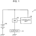
- Fig. 1 is a block diagram of a glow plug controller 21 according to a first embodiment of the present invention.
- the glow plug controller 21 includes a glow plug 10, a controlling unit 32, and a switch 33.
- a glow plug 10 is shown, an actual engine is provided with a plurality of cylinders, and a plurality of the glow plugs 10 and a plurality of the switches 33 are provided in correspondence with the respective cylinders.
- the controlling unit 32 is formed as a microcomputer including, for example, a CPU, ROM, and RAM.
- the controlling unit 32 controls the transmission of electricity to the glow plug 10 by performing pulse width modulation (PWN) control.
- the controlling unit 32 is capable of calculating applied voltage to the glow plug 10 on the basis of an input voltage.
- the switch 33 is switched between transmission-on and transmission-off of electricity to the glow plug 10 from a battery VA.
- the switch 33 is formed to operate a field effect transistor (FET) having a current detecting function via, for example, an NPN transistor.
- FET field effect transistor
- the controlling unit 32 obtains the resistance value of the glow plug 10 on the basis of the applied voltage and electric current that flows through the glow plug 10 and that is measured by the switch 33.
- the controlling unit 32 when an energy key is turned on, the controlling unit 32 is capable of performing pre-glow transmission of electricity that rapidly raises the temperature of the glow plug 10, and of performing an after-glow transmission of electricity that maintains the glow plug 10 at a predetermined temperature for a predetermined time.
- the controlling unit 32 performs a rapid temperature raising operation in which, by applying a voltage of 11 V to the glow plug 10, the surface temperature at a position that is 2 mm from a rear end side in an axial direction OD from a front end (described later) of a sheath tube of the glow plug 10 is raised to 1000°C or greater in 3 seconds or less from the start of the application of the voltage.
- the controlling unit 32 rapidly raises the temperature of the glow plug 10 to a target temperature by causing a curve that indicates the relationship between electric power applied to the glow plug 10 and an elapsed time to coincide with a previously formed reference curve.
- the controlling unit 32 determines the electric power to be applied to the glow plug 10 at each time in accordance with an elapsed time from the start of transmission of electricity by using tables of relational expressions indicating a predetermined reference curve.
- the controlling unit 32 determines the voltage to be applied to the glow plug 10 on the basis of the relationship between the electric current that flows through the glow plug 10 and a value of the electric power to be applied to the glow plug 10 at that point in time; and controls the voltage that is applied to the glow plug 10 by performing the PWM control.
- the electric power is applied such that a curve that is the same as the reference curve is drawn, and the glow plug 10 is heated in correspondence with the integrated quantity of the electric power applied up to each point in time in the temperature raising process. Therefore, when the application of electric power in accordance with the reference curve is completed, the temperature of the glow plug 10 reaches the target temperature at a time that is in accordance with the reference curve.
- the supply electric power to the glow plug 10 is adjusted such that the surface temperature of the sheath tube of the glow plug 10 is 1000°C or greater during a relatively long period of time (such as approximately 180 seconds).
- the controlling unit 32 controls the transmission of electricity to the glow plug 10 such that the resistance value of the glow plug 10 is the same as a resistance value (target resistance value) occurring at the target temperature.
- the controlling unit 32 performs, for example, proportional-integral (PI) control to calculate an effective voltage to be applied to the glow plug 10 and sets a duty ratio, which is equal to the pulse width divided by the pulse period, on the basis of the calculated effective voltage, so that the transmission of electricity is controlled.
- PI proportional-integral
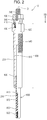
- Fig. 2 illustrates the glow plug 10 of the glow plug controller 21.
- the glow plug 10 includes a sheath heater (heating device) 800 that generates heat, and functions as a heat source that helps ignition when starting an internal combustion engine (not shown) such as a diesel engine as a typical example.
- the glow plug 10 includes, in addition to the sheath heater 800, a center shaft 200, and a metal shell 500. These members that make up the glow plug 10 are assembled along the axial direction OD of the glow plug 10.
- Fig. 2 illustrates an external structure on the right side of an axial line O in the plane of Fig. 2 , and a sectional structure on the left side of the axial line O in the plane of Fig. 2 .
- the side of the sheath heater 800 of the glow plug 10 is called a "front end side”
- the side of an engaging member 100 is called a "rear end side”.
- the metal shell 500 is a member that is formed by forming carbon steel into a cylindrical shape.
- a front-end-side end portion of the metal shell 500 holds the sheath heater 800.
- a rear-end-side end portion of the metal shell 500 holds the center shaft 200 via an insulating member 410 and an O ring 460.
- the position of the insulating member 410 along the axial line O is fixed by crimping a ring 300 that contacts a rear end of the insulating member 410 to the center shaft 200.
- a portion of the center shaft 200 extending from the insulating member 410 to the sheath heater 800 is disposed in an axial hole 510 of the metal shell 500.
- the axial hole 510 is a through hole formed along the axial line O, and has a diameter that is larger than the diameter of the center shaft 200. With the center shaft 200 positioned in the axial hole 510, a gap that electrically insulates the axial hole 510 and the center shaft 200 from each other is formed between the axial hole 510 and the center shaft 200.
- the sheath heater 800 is press-fitted and joined to a front-end side of the axial hole 510.
- the metal shell 500 includes a tool engaging portion 520 and an externally threaded portion 540.
- the tool engaging portion 520 of the metal shell 500 engages with a tool (not shown) that is used in mounting and dismounting the glow plug 10.
- the externally threaded portion 540 is fitted to an external thread of an internal combustion engine (not shown).
- the center shaft 200 is a member that is formed by forming a conductive material into a circular cylindrical shape (rod shape). With the center shaft 200 being inserted in the axial hole 510 of the metal shell 500, the center shaft 200 is assembled along the axial line O.
- the center shaft 200 includes a front end portion 210 that is formed at the front end side, and an externally threaded portion 290 that is provided at the rear end side.
- the front end portion 210 is inserted in the sheath heater 800.
- the externally threaded portion 290 protrudes towards the rear end side from the metal shell 500.
- the engaging member 100 is fitted to the externally threaded portion 290.
- Fig. 3 is a sectional view of a detailed structure of the sheath heater 800.
- the sheath heater 800 includes a sheath tube 810, a front end coil 820, a rear end coil 830, and an insulator 870.
- the sheath tube 810 is a cylindrical member that extends in the axial direction OD and whose front end is closed.
- the sheath tube 810 accommodates the front end coil 820, the rear end coil 830, and the insulator 870.
- the sheath tube 810 includes a side surface portion 814 that extends in the axial direction OD, a front end portion 813 that is connected to a front end side of the side surface portion 814 and that is rounded towards an outer side, and a rear end portion 819 that is an end portion that is open at a side opposite to the front end portion 813.
- the front end portion 210 of the center shaft 200 is inserted in the sheath tube 810 from the rear end portion 819.
- the sheath tube 810 is electrically insulated from the center shaft 200 by packing 600 and the insulator 870. On the other hand, the sheath tube 810 contacts and is electrically connected to the metal shell 500.
- the sheath tube 810 is made of, for example, austenitic stainless steel materials containing iron (Fe), chromium (Cr), and carbon (C); or nickel (Ni) based alloys, such as Inconel 601 (Inconel is a trademark) and alloy 602 (corresponding to DIN2.4633 alloy according to German Industry Standard (DIN)).
- the insulator 870 is made of an electrically insulating material powder.
- magnesium oxide (MgO) powder is used for the insulator 870.
- the front end coil 820 is disposed along the axial direction OD at an inner side of the sheath tube 810, and is heated by the transmission of electricity.
- the front end coil 820 includes a front end portion 822, which is a front-end-side coil end portion, and a rear end portion 828, which is a rear-end-side coil end portion.
- the front end portion 822 is positioned in the front end portion 813 of the sheath tube 810, and is electrically connected to the sheath tube 810.
- the front end portion 822 is embedded in the front end portion 813 of the sheath tube 810 while being surrounded by the front end portion 813 of the sheath tube 810.
- the rear end portion 828 is electrically connected to the rear end coil 830 via a connection portion 840 formed by welding the front end coil 820 and the rear end coil 830 to each other.
- the main component of the front end coil 820 are tungsten (W) and molybdenum (Mo).
- the term "main component” refers to a substance whose percentage content (mass%) is 50 mass% or greater. It is desirable that the main component of the front end coil 820 be tungsten (W), and the percentage content of tungsten (W) in the front end coil 820 be 99 mass% or greater. In the embodiment, the main component of the front end coil 820 is tungsten (W), and the percentage content of tungsten (W) in the front end coil 820 is 99 mass% or greater.
- the wire diameter of the front end coil is 0.20 mm.
- a length L of one turn of the front end coil 820 from the connection portion 840 as a starting point along the axial direction OD is greater than an average pitch of the front end coil 820.
- the pitch refers to an interval between spiral portions of the coil (such as an interval p shown in Fig. 3 ).
- the average pitch of the front end coil 820 refers to an average of intervals at a location where gaps between spiral portions of the front end coil 820 is stable.
- the average pitch of the front end coil 820 is determined on the basis of the average of intervals between spiral portions at a portion T in Fig. 3 excluding intervals between spiral portions for three turns from a front-end-side inner wall surface 812 of the sheath tube 810 to the back end side and intervals between spiral portions for three turns from the connection portion 840 to the front end side.
- the rear end coil 830 includes a front end portion 832, which is a front-end-side coil end portion, and a rear end portion 839, which is a rear-end-side coil end portion.
- the front end portion 832 is electrically connected to the front end coil 820 via the connection portion 840.
- the rear end portion 839 is electrically connected to the center shaft 200.
- the melting point of the rear end coil 830 is lower than the melting point of the front end coil 820.
- the rear end coil 830 is made of, for example, an alloy of nickel (Ni) and chromium (Cr) or an alloy of iron (Fe), chromium (Cr), and aluminum (Al).
- the wire diameter of the rear end coil 830 is 0.40 mm, and is greater than the wire diameter of the front end coil 820.
- a resistance value R 20 of the glow plug 10 at 20°C be 0.6 ⁇ or less.
- the resistance value R 20 at 20°C of the glow plug 10 refers to the total of the resistance value of the front end coil 820 at 20°C and the resistance value of the rear end coil 830 at 20°C.
- the resistance value R 20 of the glow plug 10 at 20°C is 0.4 ⁇ .
- a resistance ratio R1 of a resistance value R1 1000 at 1000°C with respect to a resistance value R1 20 of the front end coil 820 at 20°C and a resistance ratio R2 of a resistance value R2 1000 at 1000°C with respect to a resistance value R2 20 of the rear end coil 830 at 20°C have a relationship of R1 > R2.
- Fig. 4 is a sectional view of the vicinity of the connection portion 840.
- the cross section of Fig. 4 is one that is formed by a plane cutting the sheath heater 800 at a portion that includes the axial line O.
- Fig. 4 illustrates spiral portions 823 of the front end coil 820, the connection portion 840 where the front end coil 820 and the rear end coil 830 are connected, spiral portions 833 of the rear end coil 830, the sheath tube 810, and the insulator 870, all of which are cut by the plane at the portion that includes the axial line O. As shown in Fig.
- part of the rear end portion 828 of the front end coil 820 is embedded in the front end portion 832 of the rear end coil 830 while being surrounded by the front end portion 832 of the rear end coil 830.
- the front end portion 822 of the front end coil 820 is positioned between a front end 811 of the sheath tube 810 and the front-end-side inner wall surface 812 of the sheath tube 810; and the front end portion 822 of the front end coil 820 is embedded in the front end portion 813 of the sheath tube 810 while being surrounded by the front end portion 813 of the sheath tube 810.
- the connection portion 840 when an alloy section 860 is formed is schematically shown in enlarged form within a broken line S shown in Fig. 4 .
- the alloy section 860 is made of an alloy of the metal making up the front end coil 820 and the metal making up the rear end coil 830.
- the alloy section 860 is composed of tungsten (W) or molybdenum (Mo) recrystallized after being melted.
- the alloy section 860 is not formed between the rear end portion 828 of the front end coil 820 and the front end portion 832 of the rear end coil 830.
- a thickness D of the alloy section 860 may be calculated by detecting the connection portion 840 by, for example, an electron probe micro analyser (EPMA).
- EPMA electron probe micro analyser
- the front end coil 820 and the rear end coil 830 are connected to each other by embedding at least part of the rear end portion 828 of the front end coil 820 in the front end portion 832 of the rear end coil 830 while being surrounded by the front end portion 832 of the rear end coil 830, the melting point of the rear end coil 830 being lower than the melting point of the front end coil 820.
- the thickness D of the alloy section 860 is 10 ⁇ m or less, it is possible to reduce the quantity of the alloy section 860 composed of recrystallized tungsten (W) or molybdenum (Mo). Therefore, since it is possible to effectively suppress embrittlement of tungsten (W) or molybdenum (Mo) at the connection portion 840, it is possible to suppress breakage of the connection portion 840.
- the wire diameter of the rear end coil 830 is greater than the wire diameter of the front end coil 820, it is possible to provide a glow plug in which the front end coil 820 and the rear end coil 830 are firmly connected to each other.
- the length L of one turn of the front end coil 820 from the connection portion 840 as a starting point along the axial direction OD is greater than the average pitch of the front end coil 820. Therefore, compared to a case in which the length L is equal to the average pitch of the front end coil 820, the quantity of the front end coil 820 near the connection portion 840 is small. Consequently, since it is possible to reduce the quantity of the front end coil 820 near the connection portion 840, it is possible to suppress a temperature rise near the connection portion 840 when electricity is transmitted to the glow plug 10, and, thus, to increase the durability of the connection portion 840.
- Fig. 5 is a flowchart of a method of producing the glow plug 10.
- the front end coil 820 and the rear end coil 830 are welded to each other (Step S10).
- the welding is performed such that the front end portion 832 of the rear end coil 830 is melted, and at least part of the rear end portion 828 of the front end coil 820 is embedded in the front end portion 832 of the rear end coil 830 while being surrounded by the front end portion 832 of the rear end coil 830.
- Step S10 is also called the "welding step”.
- the rear end coil 830 used in the embodiment has a wire diameter that is greater than the wire diameter of the front end coil 820.
- Fig. 6 is an explanatory view of the welding step.
- the front end coil 820 and the rear end coil 830 are disposed such that the rear end portion 828 of the front end coil 820 and the front end portion 832 of the rear end coil 830 are close to each other.
- Such an arrangement can be maintained by, for example, contacting an inner peripheral surface of the front end coil 820 and an inner peripheral surface of the rear end coil 830 by a metal rod.
- the front end coil 820 and the rear end coil 830 are welded to each other.
- the output of a welding device and the welding time are adjusted such that the front end coil 820 and the rear end coil 830 are welded at a temperature that is lower than the melting point of the front end coil 820 and that is higher than the melting point of the rear end coil 830.
- the melting of the front end coil 820 is suppressed, whereas the rear end coil 830 is melted. Therefore, at least part of the rear end portion 828 of the front end coil 820 is embedded in the front end portion 832 of the rear end coil 830 that has been melted and solidified while being surrounded by the front end portion 832 of the rear end coil 830.
- the thickness of the alloy section be 10 ⁇ m or less by adjusting, for example, the output of the welding device and the welding time.
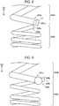
- Fig. 7 illustrates a state in which the front end coil 820 and the rear end coil 830 are welded to each other.
- Fig. 7 illustrates the connection portion 840 where the front end coil 820 and the rear end coil 830 are connected formed in the welding step.
- a rear end 829 (see Fig. 6 ) of the front end coil 820 is embedded in the front end portion 832 including a front end 831 (see Fig. 6 ) of the rear end coil 830 that has been melted and solidified while being surrounded by the front end portion 832. Therefore, the rear end 829 of the front end coil 820 and the front end 831 of the rear end coil 830, which are shown in Fig. 6 , do not appear in Fig. 7 .
- the length of one turn of the front end coil 820 from the connection portion 840 as a starting point along the axial direction OD is greater than the average pitch of the front end coil 820.
- Step S15 the rear end coil 830 and the center shaft 200 are welded to each other. More specifically, the rear end portion 839 of the rear end coil 830 connected to the front end coil 820 and the front end portion 210 of the center shaft 200 are welded to each other.
- Step S20 the front end coil 820 and the sheath tube 810 are welded to each other.
- a sheath tube material having an open front end portion and formed such that its diameter becomes gradually smaller towards the opening is prepared.
- the front end portion 822 of the front end coil 820 is inserted and disposed in the front end portion (opening) of the sheath tube material.
- the front end portion 822 of the front end coil 820 and the front end portion 813 of the sheath tube 810 are welded to each other.
- the front end portion 822 of the front end coil 820 is surrounded by and embedded in the front end portion 813 of the sheath tube 810.
- Step S30 the interior of the sheath tube 810 is filled with the insulator 870 (Step S30).
- a gap in the sheath tube 810 is filled with the insulator 870, so that the assembly of the sheath heater 800 is completed.
- Swaging is a process in which a striking force is applied to the sheath heater 800 to reduce the diameter of the sheath heater 800, and densifying the insulator 870 with which the interior of the sheath tube 810 has been filled.
- the striking force is applied to the sheath heater 800 by the swaging, the striking force is transmitted to the interior of the sheath heater 800, so that the insulator 870 is densified.
- Step S50 When the swaging has been performed on the sheath heater 800, the sheath heater 800 and the entire metal shell 500 are assembled, so that the glow plug 10 is assembled (Step S50), and is completed. More specifically, the sheath heater 800 with which the center shaft 200 has been integrated is press-fitted and fixed to the axial hole 510 of the metal shell 500, and, at a rear end portion of the metal shell 500, the O ring 460 and the insulating member 410 are fitted to the center shaft 200, and the engaging member 100 is fastened tightly to the externally threaded portion 290 of the center shaft 200 at the rear end of the metal shell 500. In Step S50, aging is performed on the glow plug 10.
- the sheath heater 800 is heated to form an oxide film on an external surface of the sheath heater 800.
- the producing method (Step S15 to Step S50) shown in Fig. 5 is merely an example. Therefore, the glow plug 10 may be produced by various other methods that differ from the producing method described above. For example, the order of Step S10 and Step S15 is changeable.
- the glow plug 10 of the embodiment described above by melting the rear end coil 830, it is possible to embed at least part of the rear end portion 828 of the front end coil 820 in the front end portion 832 of the rear end coil 830 while being surrounded by the front end portion 832 of the rear end coil 830.
- the front end coil 820 and the rear end coil 830 it is possible to connect the front end coil 820 and the rear end coil 830 to each other without melting the front end coil 820 by a large amount, so that it is possible to suppress embrittlement caused by recrystallization of tungsten (W) or molybdenum (Mo), each being a main component of the front end coil 820, and, thus, to suppress breakage of the connection portion 840 where the front end coil 820 and the rear end coil 830 are connected.
- the output of the welding device need not be increased up to the output at which the front end coil 820 whose main component is tungsten (W) or molybdenum (Mo) having a high melting point is melted, it is possible to reduce a load that is applied to the welding device.
- the welding is performed by performing laser welding, it is possible to melt a desired portion of the rear end coil 830 and connect the front end coil 820 and the rear end coil 830 to each other.
- the wire diameter of the rear end coil 830 is greater than the wire diameter of the front end coil 820, it is possible to easily surround the rear end portion 828 of the front end coil 820 by the front end portion 832 of the rear end coil 830 compared to a case in which the wire diameter of the rear end coil 830 and the wire diameter of the front end coil 820 are the same and a case in which the wire diameter of the rear end coil 830 is less than the wire diameter of the front end coil 820. In addition, it is possible to more firmly surround the rear end portion 828 of the front end coil 820 by the front end portion 832 of the rear end coil 830.
- a structure of a glow plug according to a second embodiment is similar to that of the glow plug 10 according to the above-described first embodiment, and is, thus, not described.
- Fig. 8 is an explanatory view of a welding step according to the second embodiment.
- the welding step in which a front end coil 820a and a rear end coil 830a are welded to each other is performed (see Step S10 Fig. 5 ).
- Step S10 Fig. 5 the welding step in which a front end coil 820a and a rear end coil 830a are welded to each other is performed.
- Step S10 Fig. 5 Even in the welding step according to the second embodiment, as in the first embodiment, by melting the rear end coil 830a, at least part of a rear end portion 828a of the front end coil 820a is embedded in a front end portion 832a of the rear end coil 830a while being surrounded by the front end portion 832a of the rear end coil 830a.
- the front end coil 820a and the rear end coil 830a are disposed such that the rear end portion 828a of the front end coil 820a and the front end portion 832a of the rear end coil 830a are close to each other.
- the rear end portion 828a of the rear end coil 830a is irradiated with laser light LZ.
- the front end portion 832a of the melted rear end coil 830a surrounds part of the rear end portion 828a of the front end coil 820a, and the front end coil 820a and the rear end coil 830a are welded to each other. Since the other steps of the method of producing the glow plug according to the second embodiment are the same as those of the method of producing the glow plug 10 according the above-described first embodiment, they are not described below.
- the method of producing the glow plug according to the second embodiment having the above-described structure by melting the rear end coil 830a, it is possible to embed at least part of the rear end portion 828a of the front end coil 820a in the front end portion 832a of the rear end coil 830a while being surrounded by the front end portion 832a of the rear end coil 830a. Therefore, the same advantages as those provided by the producing method according to the above-described first embodiment are provided.
- the front end portion 832a of the rear end coil 830a is irradiated with the laser light LZ, it is possible to suppress the melting of the front end coil 820a. Therefore, it is possible to effectively suppress embrittlement caused by recrystallization of tungsten (W) or molybdenum (Mo), each being a main component of the front end coil 820a.
- the rear end 829 of the front end coil 820 is embedded in the front end portion 832 including the front end 831 of the rear end coil 830 that has been melted and solidified while being surrounded by the front end portion 832 (see Fig. 7 ).
- at least one of the rear end 829 of the front end coil 820 and the front end 831 of the rear end coil 830 may protrude from the connection portion 840.
- Fig. 9 illustrates the vicinity of a connection portion 840b according to a modification.
- a rear end 829b of a front end coil 820b protrudes from the connection portion 840b shown in Fig. 9 .
- the thickness D of the alloy section 860 is 10 ⁇ m or less, the thickness D of the alloy section 860 may be greater than 10 ⁇ m.
- the wire diameters of the rear end coils 830 and 830a are greater than the wire diameters of the front end coils 820 and 820a.
- the wire diameters of the rear end coils 830 and 830a may be the same as or less than the wire diameters of the front end coils 820 and 820a.
- the length L of one turn of the front end coil 820 from the connection portion 840 as a starting point along the axial direction OD is greater than the average pitch of the front end coil 820.
- the length L may be the same as or less than the average pitch of the front end coil 820.
- the front end coil 820 and the rear end coil 830 are welded to each other by using the laser light LZ.
- the front end coil 820 and the rear end coil 830 may be welded to each other by other welding methods, such as arc welding.
- the glow plug 10 includes the front end coil 820, the front end coil 820a, or the front end coil 820b, and the rear end coil 830, the rear end coil 830a, or the rear end coil 830b.
- the rear end coils 830, 830a, and 830b of the respective glow plugs 10 may be formed by connecting a plurality of coils.
- the glow plug controller 21 includes the glow plug 10, the controlling unit 32, and the switch 33.
- the glow plug controller 21 may include the glow plug 10 and the controlling unit 32.
- the present invention is not limited to the above-described embodiments and modifications, so that various structures can be realized within a scope that does not depart from the gist of the present invention.
- any of the technical features in the embodiments and modifications corresponding to the technical features in the aspects and forms described in the "Summary of Invention" section may be replaced with another or may be combined with another as appropriate for solving some or all of the aforementioned problems or for realizing some or all of the aforementioned advantages. If the technical features thereof are not described as being essential in the specification, they may be omitted as appropriate.
Landscapes
- Engineering & Computer Science (AREA)
- Chemical & Material Sciences (AREA)
- Combustion & Propulsion (AREA)
- Mechanical Engineering (AREA)
- General Engineering & Computer Science (AREA)
- Resistance Heating (AREA)
Description
- The present invention relates to a method of producing a glow plug and the glow plug.
- A glow plug including a sheath tube that extends in an axial direction, a front end coil whose front end portion is connected to a front end portion of the sheath tube, and a rear end coil whose front end portion is connected to a rear end portion of the front end coil is known. For example, in a glow plug described in PTL 1, as a front end coil, a coil that uses tungsten (W) or molybdenum (Mo) is used.
-
- PTL 1: International Publication No.
2011/162074 - PTL 2: Japanese Unexamined Patent Application Publication No.
2014-59086 - PTL 3: Japanese Unexamined Patent Application Publication No.
2015-14393 - However, when tungsten (W) or molybdenum (Mo) is used for the front end coil, tungsten (W) or molybdenum (Mo) undergoes embrittlement as a result of being recrystallized after being melted at a high temperature. Therefore, in connecting the front end coil and the rear end coil to each other, if the melting amount of the front end coil is large, a connection portion where the front end coil and the rear end coil are connected may break. Consequently, there is a demand for a technology that, in connecting the front end coil and the rear end coil to each other, suppresses the melting amount of the front end coil and, thus, suppresses breakage of the connection portion.
- Accordingly, the present invention is made for overcoming the aforementioned problem, and can be realized in the following aspects and forms.
- According to a first aspect of the present invention, there is provided a method of producing a glow plug including a sheath tube that extends in an axial direction and whose front end is closed, a front end coil that is disposed in the sheath tube and that is connected to a front end portion of the sheath tube, and a rear end coil that is disposed in the sheath tube and that is connected to a rear end portion of the front end coil. The method includes a welding step of, by melting a front end portion of the rear end coil, welding the rear end portion of the front end coil and the front end portion of the rear end coil such that at least part of the rear end portion of the front end coil is embedded in the front end portion of the rear end coil while being surrounded by the front end portion of the rear end coil. In the method, a main component of the front end coil is tungsten (W) or molybdenum (Mo), and a melting point of the rear end coil is lower than a melting point of the front end coil. If the producing method according to the first aspect is used, it is possible to connect the front end coil and the rear end coil to each other without melting the front end coil by a large amount, so that it is possible to suppress embrittlement caused by recrystallization of tungsten (W) or molybdenum (Mo), each being a main component of the front end coil, and, thus, to suppress breakage of a connection region where the front end coil and the rear end coil are connected.
- In a first form of the producing method according to the first aspect, in the welding step, the welding is performed by laser welding. If the producing method according to the first form is used, it is possible to melt a desired portion of the rear end coil and connect the front end coil and the rear end coil to each other.
- In a second form of the producing method according to the first aspect, the laser welding is performed by irradiating the front end portion of the rear end coil with laser light. If the producing method according to the second form is used, since the front end portion of the rear end coil is irradiated with laser light, it is possible to suppress melting of the front end coil. Therefore, it is possible to effectively suppress embrittlement caused by recrystallization of tungsten (W) or molybdenum (Mo), each being a main component of the front end coil.
- According to a second aspect of the present invention, there is provided a glow plug including a sheath tube that extends in an axial direction and whose front end is closed, a front end coil that is disposed in the sheath tube and that is connected to a front end portion of the sheath tube, and a rear end coil that is disposed in the sheath tube and that is connected to a rear end portion of the front end coil. The glow plug also includes a connection portion in which at least part of the rear end portion of the front end coil is embedded in a front end portion of the rear end coil while being surrounded by the front end portion of the rear end coil. In the glow plug, a main component of the front end coil is tungsten (W) or molybdenum (Mo), and a melting point of the rear end coil is lower than a melting point of the front end coil. If the glow plug according to the second aspect is used, the front end coil and the rear end coil are connected to each other by embedding at least part of the rear end portion of the front end coil in the front end portion of the rear end coil while being surrounded by the front end portion of the rear end coil, the melting point of the rear end coil being lower than the melting point of the front end coil. Therefore, recrystallization of tungsten (W) or molybdenum (Mo) at the connection portion where the front end coil and the rear end coil are connected is suppressed, and, thus, it is possible to suppress breakage of the connection portion caused by embrittlement of the recrystallized tungsten (W) or molybdenum (Mo).
- In a first form of the glow plug according to the second aspect, a thickness of an alloy section that is disposed between the rear end portion of the front end coil and the front end portion of the rear end coil at the connection portion and that is made of an alloy of a metal making up the front end coil and a metal making up the rear end coil is 10 µm or less. If the glow plug according to the first form is used, it is possible to reduce the quantity of the alloy section composed of recrystallized tungsten (W) or molybdenum (Mo). Therefore, it is possible to effectively suppress breakage of the connection portion caused by embrittlement of tungsten (W) or molybdenum (Mo) at the alloy section.
- In a second form of the glow plug according to the second aspect, a wire diameter of the rear end coil is greater than a wire diameter of the front end coil. If the glow plug according to the second form is used, the glow plug may be a plug in which the front end coil and the rear end coil are firmly connected to each other.
- In a third form of the glow plug according to the second aspect, a length of one turn of the front end coil from the connection portion as a starting point along the axial direction is greater than an average pitch of the front end coil. If the glow plug according to the third form is used, since it is possible to reduce the quantity of the front end coil near the connection portion, it is possible to suppress a temperature rise near the connection portion when electricity is transmitted to the glow plug, and, thus, to increase the durability of the connection portion.
- The present invention may be realized in various forms, such as a sheath heater and a controller including a glow plug, in addition to the method of producing a glow plug and the glow plug described above.
-
-
Fig. 1 is a block diagram of a glow plug controller according to a first embodiment of the present invention; -
Fig. 2 illustrates a glow plug of the glow plug controller; -
Fig. 3 is a sectional view of a detailed structure of a sheath heater; -
Fig. 4 is a sectional view of the vicinity of a connection portion; -
Fig. 5 is a flowchart of a method of producing the glow plug; -
Fig. 6 is an explanatory view of a welding step; -
Fig. 7 illustrates a state in which a front end coil and a rear end coil are welded to each other; -
Fig. 8 is an explanatory view of a welding step according to a second embodiment; and -
Fig. 9 illustrates the vicinity of a connection portion according to a modification. -
Fig. 1 is a block diagram of aglow plug controller 21 according to a first embodiment of the present invention. Theglow plug controller 21 includes aglow plug 10, a controllingunit 32, and aswitch 33. Although, inFig. 1 , only oneglow plug 10 is shown, an actual engine is provided with a plurality of cylinders, and a plurality of theglow plugs 10 and a plurality of theswitches 33 are provided in correspondence with the respective cylinders. - The controlling
unit 32 is formed as a microcomputer including, for example, a CPU, ROM, and RAM. The controllingunit 32 controls the transmission of electricity to theglow plug 10 by performing pulse width modulation (PWN) control. The controllingunit 32 is capable of calculating applied voltage to theglow plug 10 on the basis of an input voltage. Theswitch 33 is switched between transmission-on and transmission-off of electricity to theglow plug 10 from a battery VA. Theswitch 33 is formed to operate a field effect transistor (FET) having a current detecting function via, for example, an NPN transistor. The controllingunit 32 obtains the resistance value of theglow plug 10 on the basis of the applied voltage and electric current that flows through theglow plug 10 and that is measured by theswitch 33. Further, in the embodiment, when an energy key is turned on, the controllingunit 32 is capable of performing pre-glow transmission of electricity that rapidly raises the temperature of theglow plug 10, and of performing an after-glow transmission of electricity that maintains theglow plug 10 at a predetermined temperature for a predetermined time. - In the pre-glow transmission of electricity, the controlling
unit 32 performs a rapid temperature raising operation in which, by applying a voltage of 11 V to theglow plug 10, the surface temperature at a position that is 2 mm from a rear end side in an axial direction OD from a front end (described later) of a sheath tube of theglow plug 10 is raised to 1000°C or greater in 3 seconds or less from the start of the application of the voltage. In the pre-glow transmission of electricity, the controllingunit 32 rapidly raises the temperature of theglow plug 10 to a target temperature by causing a curve that indicates the relationship between electric power applied to theglow plug 10 and an elapsed time to coincide with a previously formed reference curve. More specifically, the controllingunit 32 determines the electric power to be applied to theglow plug 10 at each time in accordance with an elapsed time from the start of transmission of electricity by using tables of relational expressions indicating a predetermined reference curve. The controllingunit 32 determines the voltage to be applied to theglow plug 10 on the basis of the relationship between the electric current that flows through theglow plug 10 and a value of the electric power to be applied to theglow plug 10 at that point in time; and controls the voltage that is applied to theglow plug 10 by performing the PWM control. By this, the electric power is applied such that a curve that is the same as the reference curve is drawn, and theglow plug 10 is heated in correspondence with the integrated quantity of the electric power applied up to each point in time in the temperature raising process. Therefore, when the application of electric power in accordance with the reference curve is completed, the temperature of theglow plug 10 reaches the target temperature at a time that is in accordance with the reference curve. - In the after-glow transmission of electricity, the supply electric power to the
glow plug 10 is adjusted such that the surface temperature of the sheath tube of theglow plug 10 is 1000°C or greater during a relatively long period of time (such as approximately 180 seconds). In the after-glow transmission of electricity, the controllingunit 32 controls the transmission of electricity to theglow plug 10 such that the resistance value of theglow plug 10 is the same as a resistance value (target resistance value) occurring at the target temperature. More specifically, on the basis of the difference between a current resistance value of theglow plug 10 and the target resistance value, the controllingunit 32 performs, for example, proportional-integral (PI) control to calculate an effective voltage to be applied to theglow plug 10 and sets a duty ratio, which is equal to the pulse width divided by the pulse period, on the basis of the calculated effective voltage, so that the transmission of electricity is controlled. -
Fig. 2 illustrates theglow plug 10 of theglow plug controller 21. Theglow plug 10 includes a sheath heater (heating device) 800 that generates heat, and functions as a heat source that helps ignition when starting an internal combustion engine (not shown) such as a diesel engine as a typical example. Theglow plug 10 includes, in addition to thesheath heater 800, acenter shaft 200, and ametal shell 500. These members that make up theglow plug 10 are assembled along the axial direction OD of theglow plug 10.Fig. 2 illustrates an external structure on the right side of an axial line O in the plane ofFig. 2 , and a sectional structure on the left side of the axial line O in the plane ofFig. 2 . In the specification, the side of thesheath heater 800 of theglow plug 10 is called a "front end side", and the side of an engagingmember 100 is called a "rear end side". - The
metal shell 500 is a member that is formed by forming carbon steel into a cylindrical shape. A front-end-side end portion of themetal shell 500 holds thesheath heater 800. A rear-end-side end portion of themetal shell 500 holds thecenter shaft 200 via an insulatingmember 410 and anO ring 460. The position of the insulatingmember 410 along the axial line O is fixed by crimping aring 300 that contacts a rear end of the insulatingmember 410 to thecenter shaft 200. Further, a portion of thecenter shaft 200 extending from the insulatingmember 410 to thesheath heater 800 is disposed in anaxial hole 510 of themetal shell 500. Theaxial hole 510 is a through hole formed along the axial line O, and has a diameter that is larger than the diameter of thecenter shaft 200. With thecenter shaft 200 positioned in theaxial hole 510, a gap that electrically insulates theaxial hole 510 and thecenter shaft 200 from each other is formed between theaxial hole 510 and thecenter shaft 200. Thesheath heater 800 is press-fitted and joined to a front-end side of theaxial hole 510. Themetal shell 500 includes atool engaging portion 520 and an externally threadedportion 540. Thetool engaging portion 520 of themetal shell 500 engages with a tool (not shown) that is used in mounting and dismounting theglow plug 10. The externally threadedportion 540 is fitted to an external thread of an internal combustion engine (not shown). - The
center shaft 200 is a member that is formed by forming a conductive material into a circular cylindrical shape (rod shape). With thecenter shaft 200 being inserted in theaxial hole 510 of themetal shell 500, thecenter shaft 200 is assembled along the axial line O. Thecenter shaft 200 includes afront end portion 210 that is formed at the front end side, and an externally threadedportion 290 that is provided at the rear end side. Thefront end portion 210 is inserted in thesheath heater 800. The externally threadedportion 290 protrudes towards the rear end side from themetal shell 500. The engagingmember 100 is fitted to the externally threadedportion 290. -
Fig. 3 is a sectional view of a detailed structure of thesheath heater 800. With thefront end portion 210 of thecenter shaft 200 being inserted in thesheath heater 800, thesheath heater 800 is pressed-fitted and joined to an inner portion of theaxial hole 510 of themetal shell 500. Thesheath heater 800 includes asheath tube 810, afront end coil 820, arear end coil 830, and aninsulator 870. - The
sheath tube 810 is a cylindrical member that extends in the axial direction OD and whose front end is closed. Thesheath tube 810 accommodates thefront end coil 820, therear end coil 830, and theinsulator 870. Thesheath tube 810 includes aside surface portion 814 that extends in the axial direction OD, afront end portion 813 that is connected to a front end side of theside surface portion 814 and that is rounded towards an outer side, and arear end portion 819 that is an end portion that is open at a side opposite to thefront end portion 813. Thefront end portion 210 of thecenter shaft 200 is inserted in thesheath tube 810 from therear end portion 819. Thesheath tube 810 is electrically insulated from thecenter shaft 200 by packing 600 and theinsulator 870. On the other hand, thesheath tube 810 contacts and is electrically connected to themetal shell 500. Thesheath tube 810 is made of, for example, austenitic stainless steel materials containing iron (Fe), chromium (Cr), and carbon (C); or nickel (Ni) based alloys, such as Inconel 601 (Inconel is a trademark) and alloy 602 (corresponding to DIN2.4633 alloy according to German Industry Standard (DIN)). - The
insulator 870 is made of an electrically insulating material powder. For example, magnesium oxide (MgO) powder is used for theinsulator 870. When thesheath tube 810 accommodates thecenter shaft 200, thefront end coil 820, and therear end coil 830, theinsulator 870 fills a gap formed in thesheath tube 810, and electrically insulates this gap. - The
front end coil 820 is disposed along the axial direction OD at an inner side of thesheath tube 810, and is heated by the transmission of electricity. Thefront end coil 820 includes afront end portion 822, which is a front-end-side coil end portion, and arear end portion 828, which is a rear-end-side coil end portion. Thefront end portion 822 is positioned in thefront end portion 813 of thesheath tube 810, and is electrically connected to thesheath tube 810. Thefront end portion 822 is embedded in thefront end portion 813 of thesheath tube 810 while being surrounded by thefront end portion 813 of thesheath tube 810. Therear end portion 828 is electrically connected to therear end coil 830 via aconnection portion 840 formed by welding thefront end coil 820 and therear end coil 830 to each other. Examples of the main component of thefront end coil 820 are tungsten (W) and molybdenum (Mo). The term "main component" refers to a substance whose percentage content (mass%) is 50 mass% or greater. It is desirable that the main component of thefront end coil 820 be tungsten (W), and the percentage content of tungsten (W) in thefront end coil 820 be 99 mass% or greater. In the embodiment, the main component of thefront end coil 820 is tungsten (W), and the percentage content of tungsten (W) in thefront end coil 820 is 99 mass% or greater. In the embodiment, the wire diameter of the front end coil is 0.20 mm. In the embodiment, as shown inFig. 3 , a length L of one turn of thefront end coil 820 from theconnection portion 840 as a starting point along the axial direction OD is greater than an average pitch of thefront end coil 820. The pitch refers to an interval between spiral portions of the coil (such as an interval p shown inFig. 3 ). The average pitch of thefront end coil 820 refers to an average of intervals at a location where gaps between spiral portions of thefront end coil 820 is stable. In the embodiment, the average pitch of thefront end coil 820 is determined on the basis of the average of intervals between spiral portions at a portion T inFig. 3 excluding intervals between spiral portions for three turns from a front-end-sideinner wall surface 812 of thesheath tube 810 to the back end side and intervals between spiral portions for three turns from theconnection portion 840 to the front end side. - The
rear end coil 830 includes afront end portion 832, which is a front-end-side coil end portion, and arear end portion 839, which is a rear-end-side coil end portion. Thefront end portion 832 is electrically connected to thefront end coil 820 via theconnection portion 840. By joining therear end portion 839 to thefront end portion 210 of thecenter shaft 200, therear end portion 839 is electrically connected to thecenter shaft 200. The melting point of therear end coil 830 is lower than the melting point of thefront end coil 820. Therear end coil 830 is made of, for example, an alloy of nickel (Ni) and chromium (Cr) or an alloy of iron (Fe), chromium (Cr), and aluminum (Al). In the embodiment, the wire diameter of therear end coil 830 is 0.40 mm, and is greater than the wire diameter of thefront end coil 820. - From the viewpoint of ensuring rapid temperature rise characteristics, it is desirable that a resistance value R20 of the
glow plug 10 at 20°C be 0.6 Ω or less. In the embodiment, the resistance value R20 at 20°C of theglow plug 10 refers to the total of the resistance value of thefront end coil 820 at 20°C and the resistance value of therear end coil 830 at 20°C. In the embodiment, the resistance value R20 of theglow plug 10 at 20°C is 0.4 Ω. In addition, in the embodiment, a resistance ratio R1 of a resistance value R11000 at 1000°C with respect to a resistance value R120 of thefront end coil 820 at 20°C and a resistance ratio R2 of a resistance value R21000 at 1000°C with respect to a resistance value R220 of therear end coil 830 at 20°C have a relationship of R1 > R2. -
Fig. 4 is a sectional view of the vicinity of theconnection portion 840. The cross section ofFig. 4 is one that is formed by a plane cutting thesheath heater 800 at a portion that includes the axial line O.Fig. 4 illustrates spiral portions 823 of thefront end coil 820, theconnection portion 840 where thefront end coil 820 and therear end coil 830 are connected, spiral portions 833 of therear end coil 830, thesheath tube 810, and theinsulator 870, all of which are cut by the plane at the portion that includes the axial line O. As shown inFig. 4 , at theconnection portion 840, part of therear end portion 828 of thefront end coil 820 is embedded in thefront end portion 832 of therear end coil 830 while being surrounded by thefront end portion 832 of therear end coil 830. In addition, in the embodiment, as shown inFig. 4 , thefront end portion 822 of thefront end coil 820 is positioned between afront end 811 of thesheath tube 810 and the front-end-sideinner wall surface 812 of thesheath tube 810; and thefront end portion 822 of thefront end coil 820 is embedded in thefront end portion 813 of thesheath tube 810 while being surrounded by thefront end portion 813 of thesheath tube 810. - The
connection portion 840 when analloy section 860 is formed is schematically shown in enlarged form within a broken line S shown inFig. 4 . Thealloy section 860 is made of an alloy of the metal making up thefront end coil 820 and the metal making up therear end coil 830. Thealloy section 860 is composed of tungsten (W) or molybdenum (Mo) recrystallized after being melted. In theglow plug 10 according to the embodiment, thealloy section 860 is not formed between therear end portion 828 of thefront end coil 820 and thefront end portion 832 of therear end coil 830. However, when thealloy section 860 is formed, it is desirable that a thickness D of thealloy section 860 be 10 µm or less. The thickness D of thealloy section 860 may be calculated by detecting theconnection portion 840 by, for example, an electron probe micro analyser (EPMA). - According to the
glow plug 10 of the embodiment having the above-described structure, thefront end coil 820 and therear end coil 830 are connected to each other by embedding at least part of therear end portion 828 of thefront end coil 820 in thefront end portion 832 of therear end coil 830 while being surrounded by thefront end portion 832 of therear end coil 830, the melting point of therear end coil 830 being lower than the melting point of thefront end coil 820. Therefore, recrystallization of tungsten (W) or molybdenum (Mo) at theconnection portion 840 where thefront end coil 820 and therear end coil 830 are connected is suppressed, and, thus, it is possible to suppress breakage of theconnection portion 840 caused by embrittlement of the recrystallized tungsten (W) or molybdenum (Mo). - Since the thickness D of the
alloy section 860 is 10 µm or less, it is possible to reduce the quantity of thealloy section 860 composed of recrystallized tungsten (W) or molybdenum (Mo). Therefore, since it is possible to effectively suppress embrittlement of tungsten (W) or molybdenum (Mo) at theconnection portion 840, it is possible to suppress breakage of theconnection portion 840. - Further, in the embodiment, since the wire diameter of the
rear end coil 830 is greater than the wire diameter of thefront end coil 820, it is possible to provide a glow plug in which thefront end coil 820 and therear end coil 830 are firmly connected to each other. - In the embodiment, the length L of one turn of the
front end coil 820 from theconnection portion 840 as a starting point along the axial direction OD is greater than the average pitch of thefront end coil 820. Therefore, compared to a case in which the length L is equal to the average pitch of thefront end coil 820, the quantity of thefront end coil 820 near theconnection portion 840 is small. Consequently, since it is possible to reduce the quantity of thefront end coil 820 near theconnection portion 840, it is possible to suppress a temperature rise near theconnection portion 840 when electricity is transmitted to theglow plug 10, and, thus, to increase the durability of theconnection portion 840. -
Fig. 5 is a flowchart of a method of producing theglow plug 10. In producing theglow plug 10, first, thefront end coil 820 and therear end coil 830 are welded to each other (Step S10). In Step S10, the welding is performed such that thefront end portion 832 of therear end coil 830 is melted, and at least part of therear end portion 828 of thefront end coil 820 is embedded in thefront end portion 832 of therear end coil 830 while being surrounded by thefront end portion 832 of therear end coil 830. Step S10 is also called the "welding step". Therear end coil 830 used in the embodiment has a wire diameter that is greater than the wire diameter of thefront end coil 820. -
Fig. 6 is an explanatory view of the welding step. In this step, first, as shown inFig. 6 , thefront end coil 820 and therear end coil 830 are disposed such that therear end portion 828 of thefront end coil 820 and thefront end portion 832 of therear end coil 830 are close to each other. Such an arrangement can be maintained by, for example, contacting an inner peripheral surface of thefront end coil 820 and an inner peripheral surface of therear end coil 830 by a metal rod. Next, by irradiating the vicinity of therear end portion 828 of thefront end coil 820 and thefront end portion 832 of therear end coil 830 with, for example, laser light LZ, thefront end coil 820 and therear end coil 830 are welded to each other. In the welding, for example, the output of a welding device and the welding time are adjusted such that thefront end coil 820 and therear end coil 830 are welded at a temperature that is lower than the melting point of thefront end coil 820 and that is higher than the melting point of therear end coil 830. By this, the melting of thefront end coil 820 is suppressed, whereas therear end coil 830 is melted. Therefore, at least part of therear end portion 828 of thefront end coil 820 is embedded in thefront end portion 832 of therear end coil 830 that has been melted and solidified while being surrounded by thefront end portion 832 of therear end coil 830. In the welding step, it is desirable that the thickness of the alloy section be 10 µm or less by adjusting, for example, the output of the welding device and the welding time. -
Fig. 7 illustrates a state in which thefront end coil 820 and therear end coil 830 are welded to each other.Fig. 7 illustrates theconnection portion 840 where thefront end coil 820 and therear end coil 830 are connected formed in the welding step. In the embodiment, a rear end 829 (seeFig. 6 ) of thefront end coil 820 is embedded in thefront end portion 832 including a front end 831 (seeFig. 6 ) of therear end coil 830 that has been melted and solidified while being surrounded by thefront end portion 832. Therefore, therear end 829 of thefront end coil 820 and thefront end 831 of therear end coil 830, which are shown inFig. 6 , do not appear inFig. 7 . As shown inFig. 7 , the length of one turn of thefront end coil 820 from theconnection portion 840 as a starting point along the axial direction OD is greater than the average pitch of thefront end coil 820. - When the welding step ends, the
rear end coil 830 and thecenter shaft 200 are welded to each other (Step S15). More specifically, therear end portion 839 of therear end coil 830 connected to thefront end coil 820 and thefront end portion 210 of thecenter shaft 200 are welded to each other. - Next, the
front end coil 820 and thesheath tube 810 are welded to each other (Step S20). In this step, a sheath tube material having an open front end portion and formed such that its diameter becomes gradually smaller towards the opening is prepared. Thefront end portion 822 of thefront end coil 820 is inserted and disposed in the front end portion (opening) of the sheath tube material. Next, with the opening of the sheath tube material being blocked by solidifying the front end portion of the sheath tube material after melting the front end portion by arc welding or the like from an outer side of the front end portion, thefront end portion 822 of thefront end coil 820 and thefront end portion 813 of thesheath tube 810 are welded to each other. By this, thefront end portion 822 of thefront end coil 820 is surrounded by and embedded in thefront end portion 813 of thesheath tube 810. - When Step S20 is completed, next, the interior of the
sheath tube 810 is filled with the insulator 870 (Step S30). By accommodating thecenter shaft 200, thefront end coil 820, and therear end coil 830 in thesheath tube 810, a gap in thesheath tube 810 is filled with theinsulator 870, so that the assembly of thesheath heater 800 is completed. - When the
sheath heater 800 has been assembled, swaging is performed on the sheath heater 800 (Step S40). Swaging is a process in which a striking force is applied to thesheath heater 800 to reduce the diameter of thesheath heater 800, and densifying theinsulator 870 with which the interior of thesheath tube 810 has been filled. When the striking force is applied to thesheath heater 800 by the swaging, the striking force is transmitted to the interior of thesheath heater 800, so that theinsulator 870 is densified. - When the swaging has been performed on the
sheath heater 800, thesheath heater 800 and theentire metal shell 500 are assembled, so that theglow plug 10 is assembled (Step S50), and is completed. More specifically, thesheath heater 800 with which thecenter shaft 200 has been integrated is press-fitted and fixed to theaxial hole 510 of themetal shell 500, and, at a rear end portion of themetal shell 500, theO ring 460 and the insulatingmember 410 are fitted to thecenter shaft 200, and the engagingmember 100 is fastened tightly to the externally threadedportion 290 of thecenter shaft 200 at the rear end of themetal shell 500. In Step S50, aging is performed on theglow plug 10. More specifically, by transmitting electricity to the assembledglow plug 10, thesheath heater 800 is heated to form an oxide film on an external surface of thesheath heater 800. The producing method (Step S15 to Step S50) shown inFig. 5 is merely an example. Therefore, theglow plug 10 may be produced by various other methods that differ from the producing method described above. For example, the order of Step S10 and Step S15 is changeable. - According to the method of producing the
glow plug 10 of the embodiment described above, by melting therear end coil 830, it is possible to embed at least part of therear end portion 828 of thefront end coil 820 in thefront end portion 832 of therear end coil 830 while being surrounded by thefront end portion 832 of therear end coil 830. Therefore, it is possible to connect thefront end coil 820 and therear end coil 830 to each other without melting thefront end coil 820 by a large amount, so that it is possible to suppress embrittlement caused by recrystallization of tungsten (W) or molybdenum (Mo), each being a main component of thefront end coil 820, and, thus, to suppress breakage of theconnection portion 840 where thefront end coil 820 and therear end coil 830 are connected. In addition, since the output of the welding device need not be increased up to the output at which thefront end coil 820 whose main component is tungsten (W) or molybdenum (Mo) having a high melting point is melted, it is possible to reduce a load that is applied to the welding device. - Further, since, in the welding step, the welding is performed by performing laser welding, it is possible to melt a desired portion of the
rear end coil 830 and connect thefront end coil 820 and therear end coil 830 to each other. - Since the wire diameter of the
rear end coil 830 is greater than the wire diameter of thefront end coil 820, it is possible to easily surround therear end portion 828 of thefront end coil 820 by thefront end portion 832 of therear end coil 830 compared to a case in which the wire diameter of therear end coil 830 and the wire diameter of thefront end coil 820 are the same and a case in which the wire diameter of therear end coil 830 is less than the wire diameter of thefront end coil 820. In addition, it is possible to more firmly surround therear end portion 828 of thefront end coil 820 by thefront end portion 832 of therear end coil 830. - A structure of a glow plug according to a second embodiment is similar to that of the
glow plug 10 according to the above-described first embodiment, and is, thus, not described. -
Fig. 8 is an explanatory view of a welding step according to the second embodiment. In producing the glow plug according to the second embodiment, first, the welding step in which afront end coil 820a and arear end coil 830a are welded to each other is performed (see Step S10Fig. 5 ). Even in the welding step according to the second embodiment, as in the first embodiment, by melting therear end coil 830a, at least part of arear end portion 828a of thefront end coil 820a is embedded in afront end portion 832a of therear end coil 830a while being surrounded by thefront end portion 832a of therear end coil 830a. More specifically, thefront end coil 820a and therear end coil 830a are disposed such that therear end portion 828a of thefront end coil 820a and thefront end portion 832a of therear end coil 830a are close to each other. Next, as shown inFig. 8 , therear end portion 828a of therear end coil 830a is irradiated with laser light LZ. By this, thefront end portion 832a of the meltedrear end coil 830a surrounds part of therear end portion 828a of thefront end coil 820a, and thefront end coil 820a and therear end coil 830a are welded to each other. Since the other steps of the method of producing the glow plug according to the second embodiment are the same as those of the method of producing theglow plug 10 according the above-described first embodiment, they are not described below. - According to the method of producing the glow plug according to the second embodiment having the above-described structure, by melting the
rear end coil 830a, it is possible to embed at least part of therear end portion 828a of thefront end coil 820a in thefront end portion 832a of therear end coil 830a while being surrounded by thefront end portion 832a of therear end coil 830a. Therefore, the same advantages as those provided by the producing method according to the above-described first embodiment are provided. - Further, in the second embodiment, since the
front end portion 832a of therear end coil 830a is irradiated with the laser light LZ, it is possible to suppress the melting of thefront end coil 820a. Therefore, it is possible to effectively suppress embrittlement caused by recrystallization of tungsten (W) or molybdenum (Mo), each being a main component of thefront end coil 820a. - In the above-described first embodiment, the
rear end 829 of thefront end coil 820 is embedded in thefront end portion 832 including thefront end 831 of therear end coil 830 that has been melted and solidified while being surrounded by the front end portion 832 (seeFig. 7 ). However, at least one of therear end 829 of thefront end coil 820 and thefront end 831 of therear end coil 830 may protrude from theconnection portion 840. -
Fig. 9 illustrates the vicinity of aconnection portion 840b according to a modification. Arear end 829b of afront end coil 820b protrudes from theconnection portion 840b shown inFig. 9 . Even if thefront end coil 820b and arear end coil 830b are connected in this way, as along as at least part of arear end portion 828b of thefront end coil 820b is embedded in afront end portion 832b of therear end coil 830b while being surrounded by thefront end portion 832b of therear end coil 830b, the advantages that are the same as those provided by the above-described embodiments are provided. - Although, in the above-described different embodiments, the thickness D of the
alloy section 860 is 10 µm or less, the thickness D of thealloy section 860 may be greater than 10 µm. - In the above-described different embodiments, the wire diameters of the rear end coils 830 and 830a are greater than the wire diameters of the front end coils 820 and 820a. However, the wire diameters of the rear end coils 830 and 830a may be the same as or less than the wire diameters of the front end coils 820 and 820a.
- In the above-described first embodiment, the length L of one turn of the
front end coil 820 from theconnection portion 840 as a starting point along the axial direction OD is greater than the average pitch of thefront end coil 820. However, the length L may be the same as or less than the average pitch of thefront end coil 820. - In the above-described first embodiment, in the welding step, the
front end coil 820 and therear end coil 830 are welded to each other by using the laser light LZ. However, in the welding step, thefront end coil 820 and therear end coil 830 may be welded to each other by other welding methods, such as arc welding. - In the above-described different embodiments and the first modification, the
glow plug 10 includes thefront end coil 820, thefront end coil 820a, or thefront end coil 820b, and therear end coil 830, therear end coil 830a, or therear end coil 830b. However, the rear end coils 830, 830a, and 830b of the respective glow plugs 10 may be formed by connecting a plurality of coils. - In the above-described first embodiment, the
glow plug controller 21 includes theglow plug 10, the controllingunit 32, and theswitch 33. However, theglow plug controller 21 may include theglow plug 10 and the controllingunit 32. - The present invention is not limited to the above-described embodiments and modifications, so that various structures can be realized within a scope that does not depart from the gist of the present invention. For example, any of the technical features in the embodiments and modifications corresponding to the technical features in the aspects and forms described in the "Summary of Invention" section may be replaced with another or may be combined with another as appropriate for solving some or all of the aforementioned problems or for realizing some or all of the aforementioned advantages. If the technical features thereof are not described as being essential in the specification, they may be omitted as appropriate.
Claims (7)
- A method of producing a glow plug (10) including a sheath tube (810) that extends in an axial direction (OD) and whose front end is closed, a front end coil (820, 820a, 820b) that is disposed in the sheath tube (810) and that is connected to a front end portion (813) of the sheath tube (810), and a rear end coil (830, 830a, 830b) that is disposed in the sheath tube (810) and that is connected to a rear end portion (828, 828a, 828b) of the front end coil (820, 820a, 820b), the method comprising:a welding step (S10) of, by melting a front end portion (832, 832a, 832b) of the rear end coil (830, 830a, 830b), welding the rear end portion (828, 828a, 828b) of the front end coil (820, 820a, 820b) and the front end portion (832, 832a, 832b) of the rear end coil (830, 830a, 830b) such that at least part of the rear end portion (828, 828a, 828b) of the front end coil (820, 820a, 820b) is embedded in the front end portion (832, 832a, 832b) of the rear end coil (830, 830a, 830b) while being surrounded by the front end portion (832, 832a, 832b) of the rear end coil (830, 830a, 830b),wherein a main component of the front end coil (820, 820a, 820b) is tungsten (W) or molybdenum (Mo), andwherein a melting point of the rear end coil (830, 830a, 830b) is lower than a melting point of the front end coil (820).
- The method according to Claim 1, wherein, in the welding step (S10), the welding is performed by laser welding.
- The method according to Claim 2, wherein the laser welding is performed by irradiating the front end portion (832a) of the rear end coil (830a) with laser light (LZ).
- A glow plug (10) comprising:a sheath tube (810) that extends in an axial direction (OD) and whose front end is closed;a front end coil (820, 820a, 820b) that is disposed in the sheath tube (810) and that is connected to a front end portion (813) of the sheath tube (810); anda rear end coil (830, 830a, 830b) that is disposed in the sheath tube (810) and that is connected to a rear end portion (828, 828a, 828b) of the front end coil (820, 820a, 820b),wherein the glow plug (10) further comprises a connection portion (840) in which at least part of the rear end portion (828, 828a, 828b) of the front end coil (820, 820a, 820b) is embedded in a front end portion (832, 832a, 832b) of the rear end coil (830, 830a, 830b) while being surrounded by the front end portion (832, 832a, 832b) of the rear end coil (830, 830a, 830b),
wherein a main component of the front end coil (820, 820a, 820b) is tungsten (W) or molybdenum (Mo), and
wherein a melting point of the rear end coil (830, 830a, 830b) is lower than a melting point of the front end coil (820). - The glow plug (10) according to Claim 4, wherein a thickness of an alloy section (860) that is disposed between the rear end portion (828, 828a, 828b) of the front end coil (820, 820a, 820b) and the front end portion (832, 832a, 832b) of the rear end coil (830, 830a, 830b) at the connection portion (840, 840b) and that is made of an alloy of a metal making up the front end coil (820, 820a, 820b) and a metal making up the rear end coil (830, 830a, 830b) is 10 µm or less.
- The glow plug (10) according to either Claim 4 or Claim 5, wherein a wire diameter of the rear end coil (830, 830a, 830b) is greater than a wire diameter of the front end coil (820, 820a, 820b).
- The glow plug (10) according to any one of Claims 4 to 6, wherein a length (L) of one turn of the front end coil (820) from the connection portion (840) as a starting point along the axial direction (OD) is greater than an average pitch of the front end coil (820).
Applications Claiming Priority (2)
| Application Number | Priority Date | Filing Date | Title |
|---|---|---|---|
| JP2015214677 | 2015-10-30 | ||
| JP2016129647A JP6771964B2 (en) | 2015-10-30 | 2016-06-30 | Glow plug manufacturing method and glow plug |
Publications (2)
| Publication Number | Publication Date |
|---|---|
| EP3163170A1 true EP3163170A1 (en) | 2017-05-03 |
| EP3163170B1 EP3163170B1 (en) | 2018-03-21 |
Family
ID=57218679
Family Applications (1)
| Application Number | Title | Priority Date | Filing Date |
|---|---|---|---|
| EP16191544.2A Active EP3163170B1 (en) | 2015-10-30 | 2016-09-29 | Method of producing glow plug and the glow plug |
Country Status (1)
| Country | Link |
|---|---|
| EP (1) | EP3163170B1 (en) |
Citations (7)
| Publication number | Priority date | Publication date | Assignee | Title |
|---|---|---|---|---|
| JPS5956615A (en) * | 1982-09-27 | 1984-04-02 | Jidosha Kiki Co Ltd | Connecting method of heat-generating substance of glow plug employed in diesel engine |
| JPS6273016A (en) * | 1985-09-24 | 1987-04-03 | Ngk Spark Plug Co Ltd | Method of manufacturing heating element of sheath glow plug |
| JPH085073A (en) * | 1994-06-14 | 1996-01-12 | Sankei Maniyufuatetsuku:Kk | Method for manufacturing glow plug heating element and heating element thereof |
| EP0834699A2 (en) * | 1996-10-04 | 1998-04-08 | Denso Corporation | Glow plug |
| JP2011162074A (en) | 2010-02-10 | 2011-08-25 | Nippon Sheet Glass Co Ltd | Glass with molding |
| JP2014059086A (en) | 2012-09-15 | 2014-04-03 | Ngk Spark Plug Co Ltd | Method of manufacturing glow plug |
| JP2015014393A (en) | 2013-07-03 | 2015-01-22 | 日本特殊陶業株式会社 | Glow plug manufacturing method |
-
2016
- 2016-09-29 EP EP16191544.2A patent/EP3163170B1/en active Active
Patent Citations (7)
| Publication number | Priority date | Publication date | Assignee | Title |
|---|---|---|---|---|
| JPS5956615A (en) * | 1982-09-27 | 1984-04-02 | Jidosha Kiki Co Ltd | Connecting method of heat-generating substance of glow plug employed in diesel engine |
| JPS6273016A (en) * | 1985-09-24 | 1987-04-03 | Ngk Spark Plug Co Ltd | Method of manufacturing heating element of sheath glow plug |
| JPH085073A (en) * | 1994-06-14 | 1996-01-12 | Sankei Maniyufuatetsuku:Kk | Method for manufacturing glow plug heating element and heating element thereof |
| EP0834699A2 (en) * | 1996-10-04 | 1998-04-08 | Denso Corporation | Glow plug |
| JP2011162074A (en) | 2010-02-10 | 2011-08-25 | Nippon Sheet Glass Co Ltd | Glass with molding |
| JP2014059086A (en) | 2012-09-15 | 2014-04-03 | Ngk Spark Plug Co Ltd | Method of manufacturing glow plug |
| JP2015014393A (en) | 2013-07-03 | 2015-01-22 | 日本特殊陶業株式会社 | Glow plug manufacturing method |
Also Published As
| Publication number | Publication date |
|---|---|
| EP3163170B1 (en) | 2018-03-21 |
Similar Documents
| Publication | Publication Date | Title |
|---|---|---|
| JPWO2011162074A1 (en) | Glow plug, manufacturing method thereof, and heating device | |
| JP2015078784A (en) | Glow plug | |
| JPWO2013157223A1 (en) | Glow plug | |
| US9702557B2 (en) | Glow plug | |
| EP3163170B1 (en) | Method of producing glow plug and the glow plug | |
| EP3163172B1 (en) | Glow plug | |
| JP6771964B2 (en) | Glow plug manufacturing method and glow plug | |
| JP6795886B2 (en) | Glow plugs and their manufacturing methods | |
| EP3358257B1 (en) | Glow plug | |
| JP6537893B2 (en) | Glow plug | |
| JP6279925B2 (en) | Glow plug | |
| JP4200045B2 (en) | Glow plug | |
| JP6771985B2 (en) | Glow plug | |
| JP6965153B2 (en) | Glow plug | |
| JP4510588B2 (en) | Glow plug | |
| JP6931566B2 (en) | Glow plug | |
| JP6720039B2 (en) | Glow plug | |
| EP3163171A1 (en) | Glow plug | |
| JP6794176B2 (en) | Glow plug | |
| JP6746453B2 (en) | Glow plug | |
| JP2013104648A (en) | Glow plug and method for manufacturing the same | |
| EP3396249B1 (en) | Glow plug | |
| JP2018185131A (en) | Glow plug | |
| JP6796957B2 (en) | Glow plug | |
| JP6689022B2 (en) | Glow plug |
Legal Events
| Date | Code | Title | Description |
|---|---|---|---|
| PUAI | Public reference made under article 153(3) epc to a published international application that has entered the european phase |
Free format text: ORIGINAL CODE: 0009012 |
|
| STAA | Information on the status of an ep patent application or granted ep patent |
Free format text: STATUS: THE APPLICATION HAS BEEN PUBLISHED |
|
| AK | Designated contracting states |
Kind code of ref document: A1 Designated state(s): AL AT BE BG CH CY CZ DE DK EE ES FI FR GB GR HR HU IE IS IT LI LT LU LV MC MK MT NL NO PL PT RO RS SE SI SK SM TR |
|
| AX | Request for extension of the european patent |
Extension state: BA ME |
|
| STAA | Information on the status of an ep patent application or granted ep patent |
Free format text: STATUS: REQUEST FOR EXAMINATION WAS MADE |
|
| 17P | Request for examination filed |
Effective date: 20170622 |
|
| RBV | Designated contracting states (corrected) |
Designated state(s): AL AT BE BG CH CY CZ DE DK EE ES FI FR GB GR HR HU IE IS IT LI LT LU LV MC MK MT NL NO PL PT RO RS SE SI SK SM TR |
|
| GRAP | Despatch of communication of intention to grant a patent |
Free format text: ORIGINAL CODE: EPIDOSNIGR1 |
|
| STAA | Information on the status of an ep patent application or granted ep patent |
Free format text: STATUS: GRANT OF PATENT IS INTENDED |
|
| GRAJ | Information related to disapproval of communication of intention to grant by the applicant or resumption of examination proceedings by the epo deleted |
Free format text: ORIGINAL CODE: EPIDOSDIGR1 |
|
| STAA | Information on the status of an ep patent application or granted ep patent |
Free format text: STATUS: REQUEST FOR EXAMINATION WAS MADE |
|
| GRAP | Despatch of communication of intention to grant a patent |
Free format text: ORIGINAL CODE: EPIDOSNIGR1 |
|
| STAA | Information on the status of an ep patent application or granted ep patent |
Free format text: STATUS: GRANT OF PATENT IS INTENDED |
|
| INTG | Intention to grant announced |
Effective date: 20171023 |
|
| INTC | Intention to grant announced (deleted) | ||
| INTG | Intention to grant announced |
Effective date: 20171117 |
|
| GRAS | Grant fee paid |
Free format text: ORIGINAL CODE: EPIDOSNIGR3 |
|
| GRAA | (expected) grant |
Free format text: ORIGINAL CODE: 0009210 |
|
| STAA | Information on the status of an ep patent application or granted ep patent |
Free format text: STATUS: THE PATENT HAS BEEN GRANTED |
|
| AK | Designated contracting states |
Kind code of ref document: B1 Designated state(s): AL AT BE BG CH CY CZ DE DK EE ES FI FR GB GR HR HU IE IS IT LI LT LU LV MC MK MT NL NO PL PT RO RS SE SI SK SM TR |
|
| REG | Reference to a national code |
Ref country code: GB Ref legal event code: FG4D |
|
| REG | Reference to a national code |
Ref country code: CH Ref legal event code: EP |
|
| REG | Reference to a national code |
Ref country code: AT Ref legal event code: REF Ref document number: 981510 Country of ref document: AT Kind code of ref document: T Effective date: 20180415 |
|
| REG | Reference to a national code |
Ref country code: IE Ref legal event code: FG4D |
|
| REG | Reference to a national code |
Ref country code: DE Ref legal event code: R096 Ref document number: 602016002135 Country of ref document: DE |
|
| REG | Reference to a national code |
Ref country code: NL Ref legal event code: MP Effective date: 20180321 |
|
| PG25 | Lapsed in a contracting state [announced via postgrant information from national office to epo] |
Ref country code: FI Free format text: LAPSE BECAUSE OF FAILURE TO SUBMIT A TRANSLATION OF THE DESCRIPTION OR TO PAY THE FEE WITHIN THE PRESCRIBED TIME-LIMIT Effective date: 20180321 Ref country code: NO Free format text: LAPSE BECAUSE OF FAILURE TO SUBMIT A TRANSLATION OF THE DESCRIPTION OR TO PAY THE FEE WITHIN THE PRESCRIBED TIME-LIMIT Effective date: 20180621 Ref country code: LT Free format text: LAPSE BECAUSE OF FAILURE TO SUBMIT A TRANSLATION OF THE DESCRIPTION OR TO PAY THE FEE WITHIN THE PRESCRIBED TIME-LIMIT Effective date: 20180321 Ref country code: CY Free format text: LAPSE BECAUSE OF FAILURE TO SUBMIT A TRANSLATION OF THE DESCRIPTION OR TO PAY THE FEE WITHIN THE PRESCRIBED TIME-LIMIT Effective date: 20180321 Ref country code: HR Free format text: LAPSE BECAUSE OF FAILURE TO SUBMIT A TRANSLATION OF THE DESCRIPTION OR TO PAY THE FEE WITHIN THE PRESCRIBED TIME-LIMIT Effective date: 20180321 |
|
| REG | Reference to a national code |
Ref country code: LT Ref legal event code: MG4D |
|
| REG | Reference to a national code |
Ref country code: FR Ref legal event code: PLFP Year of fee payment: 3 |
|
| REG | Reference to a national code |
Ref country code: AT Ref legal event code: MK05 Ref document number: 981510 Country of ref document: AT Kind code of ref document: T Effective date: 20180321 |
|
| PG25 | Lapsed in a contracting state [announced via postgrant information from national office to epo] |
Ref country code: BG Free format text: LAPSE BECAUSE OF FAILURE TO SUBMIT A TRANSLATION OF THE DESCRIPTION OR TO PAY THE FEE WITHIN THE PRESCRIBED TIME-LIMIT Effective date: 20180621 Ref country code: RS Free format text: LAPSE BECAUSE OF FAILURE TO SUBMIT A TRANSLATION OF THE DESCRIPTION OR TO PAY THE FEE WITHIN THE PRESCRIBED TIME-LIMIT Effective date: 20180321 Ref country code: GR Free format text: LAPSE BECAUSE OF FAILURE TO SUBMIT A TRANSLATION OF THE DESCRIPTION OR TO PAY THE FEE WITHIN THE PRESCRIBED TIME-LIMIT Effective date: 20180622 Ref country code: LV Free format text: LAPSE BECAUSE OF FAILURE TO SUBMIT A TRANSLATION OF THE DESCRIPTION OR TO PAY THE FEE WITHIN THE PRESCRIBED TIME-LIMIT Effective date: 20180321 Ref country code: SE Free format text: LAPSE BECAUSE OF FAILURE TO SUBMIT A TRANSLATION OF THE DESCRIPTION OR TO PAY THE FEE WITHIN THE PRESCRIBED TIME-LIMIT Effective date: 20180321 |
|
| PG25 | Lapsed in a contracting state [announced via postgrant information from national office to epo] |
Ref country code: NL Free format text: LAPSE BECAUSE OF FAILURE TO SUBMIT A TRANSLATION OF THE DESCRIPTION OR TO PAY THE FEE WITHIN THE PRESCRIBED TIME-LIMIT Effective date: 20180321 Ref country code: RO Free format text: LAPSE BECAUSE OF FAILURE TO SUBMIT A TRANSLATION OF THE DESCRIPTION OR TO PAY THE FEE WITHIN THE PRESCRIBED TIME-LIMIT Effective date: 20180321 Ref country code: EE Free format text: LAPSE BECAUSE OF FAILURE TO SUBMIT A TRANSLATION OF THE DESCRIPTION OR TO PAY THE FEE WITHIN THE PRESCRIBED TIME-LIMIT Effective date: 20180321 Ref country code: PL Free format text: LAPSE BECAUSE OF FAILURE TO SUBMIT A TRANSLATION OF THE DESCRIPTION OR TO PAY THE FEE WITHIN THE PRESCRIBED TIME-LIMIT Effective date: 20180321 Ref country code: AL Free format text: LAPSE BECAUSE OF FAILURE TO SUBMIT A TRANSLATION OF THE DESCRIPTION OR TO PAY THE FEE WITHIN THE PRESCRIBED TIME-LIMIT Effective date: 20180321 Ref country code: ES Free format text: LAPSE BECAUSE OF FAILURE TO SUBMIT A TRANSLATION OF THE DESCRIPTION OR TO PAY THE FEE WITHIN THE PRESCRIBED TIME-LIMIT Effective date: 20180321 |
|
| PG25 | Lapsed in a contracting state [announced via postgrant information from national office to epo] |
Ref country code: SK Free format text: LAPSE BECAUSE OF FAILURE TO SUBMIT A TRANSLATION OF THE DESCRIPTION OR TO PAY THE FEE WITHIN THE PRESCRIBED TIME-LIMIT Effective date: 20180321 Ref country code: AT Free format text: LAPSE BECAUSE OF FAILURE TO SUBMIT A TRANSLATION OF THE DESCRIPTION OR TO PAY THE FEE WITHIN THE PRESCRIBED TIME-LIMIT Effective date: 20180321 Ref country code: CZ Free format text: LAPSE BECAUSE OF FAILURE TO SUBMIT A TRANSLATION OF THE DESCRIPTION OR TO PAY THE FEE WITHIN THE PRESCRIBED TIME-LIMIT Effective date: 20180321 Ref country code: SM Free format text: LAPSE BECAUSE OF FAILURE TO SUBMIT A TRANSLATION OF THE DESCRIPTION OR TO PAY THE FEE WITHIN THE PRESCRIBED TIME-LIMIT Effective date: 20180321 |
|
| PG25 | Lapsed in a contracting state [announced via postgrant information from national office to epo] |
Ref country code: PT Free format text: LAPSE BECAUSE OF FAILURE TO SUBMIT A TRANSLATION OF THE DESCRIPTION OR TO PAY THE FEE WITHIN THE PRESCRIBED TIME-LIMIT Effective date: 20180723 |
|
| REG | Reference to a national code |
Ref country code: DE Ref legal event code: R097 Ref document number: 602016002135 Country of ref document: DE |
|
| PLBE | No opposition filed within time limit |
Free format text: ORIGINAL CODE: 0009261 |
|
| STAA | Information on the status of an ep patent application or granted ep patent |
Free format text: STATUS: NO OPPOSITION FILED WITHIN TIME LIMIT |
|
| PG25 | Lapsed in a contracting state [announced via postgrant information from national office to epo] |
Ref country code: DK Free format text: LAPSE BECAUSE OF FAILURE TO SUBMIT A TRANSLATION OF THE DESCRIPTION OR TO PAY THE FEE WITHIN THE PRESCRIBED TIME-LIMIT Effective date: 20180321 |
|
| 26N | No opposition filed |
Effective date: 20190102 |
|
| PG25 | Lapsed in a contracting state [announced via postgrant information from national office to epo] |
Ref country code: MC Free format text: LAPSE BECAUSE OF FAILURE TO SUBMIT A TRANSLATION OF THE DESCRIPTION OR TO PAY THE FEE WITHIN THE PRESCRIBED TIME-LIMIT Effective date: 20180321 |
|
| PG25 | Lapsed in a contracting state [announced via postgrant information from national office to epo] |
Ref country code: SI Free format text: LAPSE BECAUSE OF FAILURE TO SUBMIT A TRANSLATION OF THE DESCRIPTION OR TO PAY THE FEE WITHIN THE PRESCRIBED TIME-LIMIT Effective date: 20180321 |
|
| REG | Reference to a national code |
Ref country code: BE Ref legal event code: MM Effective date: 20180930 |
|
| REG | Reference to a national code |
Ref country code: IE Ref legal event code: MM4A |
|
| PG25 | Lapsed in a contracting state [announced via postgrant information from national office to epo] |
Ref country code: LU Free format text: LAPSE BECAUSE OF NON-PAYMENT OF DUE FEES Effective date: 20180929 |
|
| PG25 | Lapsed in a contracting state [announced via postgrant information from national office to epo] |
Ref country code: IE Free format text: LAPSE BECAUSE OF NON-PAYMENT OF DUE FEES Effective date: 20180929 |
|
| PG25 | Lapsed in a contracting state [announced via postgrant information from national office to epo] |
Ref country code: BE Free format text: LAPSE BECAUSE OF NON-PAYMENT OF DUE FEES Effective date: 20180930 |
|
| PGFP | Annual fee paid to national office [announced via postgrant information from national office to epo] |
Ref country code: FR Payment date: 20190815 Year of fee payment: 4 Ref country code: IT Payment date: 20190930 Year of fee payment: 4 |
|
| PG25 | Lapsed in a contracting state [announced via postgrant information from national office to epo] |
Ref country code: MT Free format text: LAPSE BECAUSE OF NON-PAYMENT OF DUE FEES Effective date: 20180929 |
|
| PG25 | Lapsed in a contracting state [announced via postgrant information from national office to epo] |
Ref country code: TR Free format text: LAPSE BECAUSE OF FAILURE TO SUBMIT A TRANSLATION OF THE DESCRIPTION OR TO PAY THE FEE WITHIN THE PRESCRIBED TIME-LIMIT Effective date: 20180321 |
|
| REG | Reference to a national code |
Ref country code: CH Ref legal event code: PL |
|
| PG25 | Lapsed in a contracting state [announced via postgrant information from national office to epo] |
Ref country code: MK Free format text: LAPSE BECAUSE OF NON-PAYMENT OF DUE FEES Effective date: 20180321 Ref country code: HU Free format text: LAPSE BECAUSE OF FAILURE TO SUBMIT A TRANSLATION OF THE DESCRIPTION OR TO PAY THE FEE WITHIN THE PRESCRIBED TIME-LIMIT; INVALID AB INITIO Effective date: 20160929 |
|
| PG25 | Lapsed in a contracting state [announced via postgrant information from national office to epo] |
Ref country code: IS Free format text: LAPSE BECAUSE OF FAILURE TO SUBMIT A TRANSLATION OF THE DESCRIPTION OR TO PAY THE FEE WITHIN THE PRESCRIBED TIME-LIMIT Effective date: 20180721 Ref country code: LI Free format text: LAPSE BECAUSE OF NON-PAYMENT OF DUE FEES Effective date: 20190930 Ref country code: CH Free format text: LAPSE BECAUSE OF NON-PAYMENT OF DUE FEES Effective date: 20190930 |
|
| GBPC | Gb: european patent ceased through non-payment of renewal fee |
Effective date: 20200929 |
|
| PG25 | Lapsed in a contracting state [announced via postgrant information from national office to epo] |
Ref country code: FR Free format text: LAPSE BECAUSE OF NON-PAYMENT OF DUE FEES Effective date: 20200930 |
|
| PG25 | Lapsed in a contracting state [announced via postgrant information from national office to epo] |
Ref country code: GB Free format text: LAPSE BECAUSE OF NON-PAYMENT OF DUE FEES Effective date: 20200929 |
|
| PG25 | Lapsed in a contracting state [announced via postgrant information from national office to epo] |
Ref country code: IT Free format text: LAPSE BECAUSE OF NON-PAYMENT OF DUE FEES Effective date: 20200929 |
|
| REG | Reference to a national code |
Ref country code: DE Ref legal event code: R081 Ref document number: 602016002135 Country of ref document: DE Owner name: NITERRA CO., LTD., NAGOYA-SHI, JP Free format text: FORMER OWNER: NGK SPARK PLUG CO., LTD., NAGOYA-SHI, AICHI, JP |
|
| PGFP | Annual fee paid to national office [announced via postgrant information from national office to epo] |
Ref country code: DE Payment date: 20250805 Year of fee payment: 10 |