EP3163037A1 - Valve device for engine - Google Patents
Valve device for engine Download PDFInfo
- Publication number
- EP3163037A1 EP3163037A1 EP15811591.5A EP15811591A EP3163037A1 EP 3163037 A1 EP3163037 A1 EP 3163037A1 EP 15811591 A EP15811591 A EP 15811591A EP 3163037 A1 EP3163037 A1 EP 3163037A1
- Authority
- EP
- European Patent Office
- Prior art keywords
- cam
- rocker arm
- valve
- drive
- camshaft
- Prior art date
- Legal status (The legal status is an assumption and is not a legal conclusion. Google has not performed a legal analysis and makes no representation as to the accuracy of the status listed.)
- Granted
Links
Images
















Classifications
-
- F—MECHANICAL ENGINEERING; LIGHTING; HEATING; WEAPONS; BLASTING
- F01—MACHINES OR ENGINES IN GENERAL; ENGINE PLANTS IN GENERAL; STEAM ENGINES
- F01L—CYCLICALLY OPERATING VALVES FOR MACHINES OR ENGINES
- F01L13/00—Modifications of valve-gear to facilitate reversing, braking, starting, changing compression ratio, or other specific operations
- F01L13/0005—Deactivating valves
-
- F—MECHANICAL ENGINEERING; LIGHTING; HEATING; WEAPONS; BLASTING
- F01—MACHINES OR ENGINES IN GENERAL; ENGINE PLANTS IN GENERAL; STEAM ENGINES
- F01L—CYCLICALLY OPERATING VALVES FOR MACHINES OR ENGINES
- F01L1/00—Valve-gear or valve arrangements, e.g. lift-valve gear
- F01L1/02—Valve drive
- F01L1/04—Valve drive by means of cams, camshafts, cam discs, eccentrics or the like
- F01L1/047—Camshafts
-
- F—MECHANICAL ENGINEERING; LIGHTING; HEATING; WEAPONS; BLASTING
- F01—MACHINES OR ENGINES IN GENERAL; ENGINE PLANTS IN GENERAL; STEAM ENGINES
- F01L—CYCLICALLY OPERATING VALVES FOR MACHINES OR ENGINES
- F01L1/00—Valve-gear or valve arrangements, e.g. lift-valve gear
- F01L1/02—Valve drive
- F01L1/04—Valve drive by means of cams, camshafts, cam discs, eccentrics or the like
- F01L1/047—Camshafts
- F01L1/053—Camshafts overhead type
-
- F—MECHANICAL ENGINEERING; LIGHTING; HEATING; WEAPONS; BLASTING
- F01—MACHINES OR ENGINES IN GENERAL; ENGINE PLANTS IN GENERAL; STEAM ENGINES
- F01L—CYCLICALLY OPERATING VALVES FOR MACHINES OR ENGINES
- F01L1/00—Valve-gear or valve arrangements, e.g. lift-valve gear
- F01L1/02—Valve drive
- F01L1/04—Valve drive by means of cams, camshafts, cam discs, eccentrics or the like
- F01L1/08—Shape of cams
-
- F—MECHANICAL ENGINEERING; LIGHTING; HEATING; WEAPONS; BLASTING
- F01—MACHINES OR ENGINES IN GENERAL; ENGINE PLANTS IN GENERAL; STEAM ENGINES
- F01L—CYCLICALLY OPERATING VALVES FOR MACHINES OR ENGINES
- F01L1/00—Valve-gear or valve arrangements, e.g. lift-valve gear
- F01L1/12—Transmitting gear between valve drive and valve
- F01L1/18—Rocking arms or levers
-
- F—MECHANICAL ENGINEERING; LIGHTING; HEATING; WEAPONS; BLASTING
- F01—MACHINES OR ENGINES IN GENERAL; ENGINE PLANTS IN GENERAL; STEAM ENGINES
- F01L—CYCLICALLY OPERATING VALVES FOR MACHINES OR ENGINES
- F01L1/00—Valve-gear or valve arrangements, e.g. lift-valve gear
- F01L1/20—Adjusting or compensating clearance
- F01L1/22—Adjusting or compensating clearance automatically, e.g. mechanically
- F01L1/24—Adjusting or compensating clearance automatically, e.g. mechanically by fluid means, e.g. hydraulically
-
- F—MECHANICAL ENGINEERING; LIGHTING; HEATING; WEAPONS; BLASTING
- F01—MACHINES OR ENGINES IN GENERAL; ENGINE PLANTS IN GENERAL; STEAM ENGINES
- F01L—CYCLICALLY OPERATING VALVES FOR MACHINES OR ENGINES
- F01L1/00—Valve-gear or valve arrangements, e.g. lift-valve gear
- F01L1/26—Valve-gear or valve arrangements, e.g. lift-valve gear characterised by the provision of two or more valves operated simultaneously by same transmitting-gear; peculiar to machines or engines with more than two lift-valves per cylinder
- F01L1/267—Valve-gear or valve arrangements, e.g. lift-valve gear characterised by the provision of two or more valves operated simultaneously by same transmitting-gear; peculiar to machines or engines with more than two lift-valves per cylinder with means for varying the timing or the lift of the valves
-
- F—MECHANICAL ENGINEERING; LIGHTING; HEATING; WEAPONS; BLASTING
- F01—MACHINES OR ENGINES IN GENERAL; ENGINE PLANTS IN GENERAL; STEAM ENGINES
- F01L—CYCLICALLY OPERATING VALVES FOR MACHINES OR ENGINES
- F01L1/00—Valve-gear or valve arrangements, e.g. lift-valve gear
- F01L1/46—Component parts, details, or accessories, not provided for in preceding subgroups
- F01L1/462—Valve return spring arrangements
-
- F—MECHANICAL ENGINEERING; LIGHTING; HEATING; WEAPONS; BLASTING
- F01—MACHINES OR ENGINES IN GENERAL; ENGINE PLANTS IN GENERAL; STEAM ENGINES
- F01L—CYCLICALLY OPERATING VALVES FOR MACHINES OR ENGINES
- F01L13/00—Modifications of valve-gear to facilitate reversing, braking, starting, changing compression ratio, or other specific operations
-
- F—MECHANICAL ENGINEERING; LIGHTING; HEATING; WEAPONS; BLASTING
- F01—MACHINES OR ENGINES IN GENERAL; ENGINE PLANTS IN GENERAL; STEAM ENGINES
- F01L—CYCLICALLY OPERATING VALVES FOR MACHINES OR ENGINES
- F01L13/00—Modifications of valve-gear to facilitate reversing, braking, starting, changing compression ratio, or other specific operations
- F01L13/0015—Modifications of valve-gear to facilitate reversing, braking, starting, changing compression ratio, or other specific operations for optimising engine performances by modifying valve lift according to various working parameters, e.g. rotational speed, load, torque
- F01L13/0036—Modifications of valve-gear to facilitate reversing, braking, starting, changing compression ratio, or other specific operations for optimising engine performances by modifying valve lift according to various working parameters, e.g. rotational speed, load, torque the valves being driven by two or more cams with different shape, size or timing or a single cam profiled in axial and radial direction
-
- F—MECHANICAL ENGINEERING; LIGHTING; HEATING; WEAPONS; BLASTING
- F01—MACHINES OR ENGINES IN GENERAL; ENGINE PLANTS IN GENERAL; STEAM ENGINES
- F01L—CYCLICALLY OPERATING VALVES FOR MACHINES OR ENGINES
- F01L1/00—Valve-gear or valve arrangements, e.g. lift-valve gear
- F01L1/02—Valve drive
- F01L1/04—Valve drive by means of cams, camshafts, cam discs, eccentrics or the like
- F01L1/047—Camshafts
- F01L1/053—Camshafts overhead type
- F01L2001/0537—Double overhead camshafts [DOHC]
-
- F—MECHANICAL ENGINEERING; LIGHTING; HEATING; WEAPONS; BLASTING
- F01—MACHINES OR ENGINES IN GENERAL; ENGINE PLANTS IN GENERAL; STEAM ENGINES
- F01L—CYCLICALLY OPERATING VALVES FOR MACHINES OR ENGINES
- F01L13/00—Modifications of valve-gear to facilitate reversing, braking, starting, changing compression ratio, or other specific operations
- F01L13/0005—Deactivating valves
- F01L2013/001—Deactivating cylinders
Definitions
- the present invention relates to a valve gear for an engine, which includes a switching mechanism configured to switch the drive form of the intake valve or the exhaust valve of the engine.
- a valve gear capable of switching the drive form of the intake valve or the exhaust valve of an engine is conventionally described in, for example, patent literature 1.
- the valve gear for an engine disclosed in patent literature 1 includes two types of rocker arms configured to convert the rotation of the cams of a camshaft into a reciprocating motion and transmit it to an intake valve or an exhaust valve, and a switching mechanism configured to switch the drive form of the intake valve or the exhaust valve.
- the cams include a first cam with a relatively large valve lift amount, and a second cam with a relatively small valve lift amount.
- the two types of rocker arms include a first rocker arm that swings when pushed by the first cam, and a second rocker arm swingably provided at a position so as to be pushed by the second cam.
- the second rocker arm includes a pushing portion that pushes the intake valve or the exhaust valve.
- the switching mechanism is formed from a slide pin that selectively connects the above-described two types of rocker arms, an actuator that applies an oil pressure to the slide pin, a return spring that returns the slide pin into one rocker arm, and the like.
- the switching mechanism switches between a form in which the first rocker arm and the second rocker arm are connected to each other and integrally swing and a form in which the two rocker arms are disconnected.
- Pin holes configured to pass the slide pin are formed in the rocker arms.
- the pin holes extend in the axial direction of the swing shafts of the rocker arms.
- the pin hole of the first rocker arm and the pin hole of the second rocker arm are formed at positions at which the pin holes are aligned on the same axis in a state in which the positions of the two rocker arms match in the swing direction.
- the first rocker arm and the second rocker arm are connected to each other when the slide pin moves to a connecting position across the two rocker arms.
- the connected state is canceled when the slide pin is moved by the spring force of the return spring to a non-connecting position at which the slide pin is stored in the one original rocker arm.
- Patent Literature 1 Japanese Patent Laid-Open No. 2009-264199
- a so-called “flick phenomenon” may occur in the process of canceling the connected state between the first rocker arm and the second rocker arm and the process of shifting from the non-connected state to the connected state.
- the flick phenomenon is a phenomenon in which the connected state between the rocker arms is canceled in a state in which the intake valve or the exhaust valve is not closed, and the second rocker arm and the intake valve or the exhaust valve are abruptly returned to the close position by the spring force of the valve spring.
- the present invention has been made to meet this requirement, and has as its object to provide a valve gear for an engine in which the period when an intake valve or an exhaust valve is kept closed synchronizes with the period when a member configured to switch the drive form of the intake valve or the exhaust valve is driven.
- a valve gear for an engine comprising a camshaft including a valve drive cam configured to drive one of an intake valve and an exhaust valve, a rocker arm having a function of converting a rotation of the valve drive cam into a reciprocating motion and transmitting the reciprocating motion to one of the intake valve and the exhaust valve, a synchronous cam configured to rotate in synchronism with the valve drive cam, and a switching mechanism configured to switch a drive form of one of the intake valve and the exhaust valve to one of a predetermined first drive form and a predetermined second drive form in a period defined by the synchronous cam, wherein the switching mechanism comprises a switching unit configured to switch the drive form by moving some of components which constitute a valve gear system from the valve drive cam to the rocker arm, and a drive unit including a cam follower that is pushed to move by the synchronous cam, and configured to drive some of the components which constitute the valve gear system in directions to switch the drive form by force received from the cam follow
- the synchronous cam pushes the cam follower, and the pushing force is transmitted to the switching unit of the switching mechanism to switch the drive form of the intake valve or the exhaust valve in the period when the intake valve or the exhaust valve is kept closed. It is therefore possible to provide a valve gear for an engine in which the switching mechanism is not driven in the period when the intake valve or the exhaust valve is open, unlike the related art, and a so-called flick phenomenon as in the related art does not occur.
- the driving force is not transmitted to the components which constitute the valve gear system from the valve drive cam to the rocker arm. When some of the components move, the resistance is considerably small, and the components can always smoothly move.
- valve gear for an engine according to one embodiment of the present invention will now be described in detail with reference to Figs. 1 to 16 .
- the valve gear for an engine according to this embodiment constitutes the inventions described in claims 1 to 3, 5, 8, and 12.
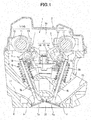
- a valve gear 1 shown in Fig. 1 is mounted on a DOHC four-cylinder engine 2 included in a vehicle (not shown).
- the valve gear 1 includes a switching mechanism 3 to switch between a full cylinder operation form in which the four cylinders are operated as usual and a partial cylinder operation form (rest form) in which two of the four cylinders are at rest.
- the switching mechanisms 3 are provided on two of the four cylinders, as will be described later in detail.
- the switching mechanisms 3 can be provided on, for example, the first and fourth cylinders located at the ends of the cylinder train or the second and third cylinders located at the center of the cylinder train.
- the switching mechanisms 3 constitute part of the valve gear 1, and are provided on both one side where an intake valve 4 is located and the other side where an exhaust valve 5 is located.
- the valve gear 1 converts the rotations of an intake camshaft 7 and an exhaust camshaft 8 provided in a cylinder head 6 into reciprocating motions by rocker arms 9, thereby driving the intake valve 4 and the exhaust valve 5.
- valve gear 1 a portion that drives the intake valve 4 and a portion that drives the exhaust valve 5 have the same structure. For this reason, as for members that have the same structure on the side of the intake valve 4 and on the side of the exhaust valve 5, the member on the side of the exhaust valve 5 will be described below.
- the member on the side of the intake valve 4 is denoted by the same reference numeral, and a description thereof will be omitted.
- Each of the intake camshaft 7 and the exhaust camshaft 8 includes a camshaft main body 11 rotatably supported in the cylinder head 6, and a valve drive cam 12 and a synchronous cam 13 both provided on the camshaft main body 11. Note that the intake camshaft 7 and the exhaust camshaft 8 will generally simply be referred to as camshafts 14 hereinafter.
- the camshaft main body 11 is formed into a rod shape with a circular section.
- the valve drive cam 12 includes a circular base portion 12a and a nose portion 12b.
- the circular base portion 12a is formed into a shape that is part of a column located on the same axis as the camshaft main body 11, and is formed into a size that brings the valve lift amount of the intake valve 4 or the exhaust valve 5 to zero.
- the nose portion 12b is formed into such a shape that projects outward in the radial direction from the circular base portion 12a by a predetermined projection amount so as to have a mountain-shaped section.
- the synchronous cam 13 defines the period when the switching mechanism 3 performs a switching operation and also serves as a power source.
- the synchronous cam 13 includes a circular base portion 13a and a nose portion 13b, and is provided at a position adjacent to the valve drive cam 12.
- the synchronous cam 13 rotates in synchronism with the valve drive cam 12.
- the circular base portion 13a of the synchronous cam 13 is formed into a shape that is part of the column located on the same axis as the camshaft main body 11.
- the nose portion 13b of the synchronous cam 13 is formed into such a shape that projects outward in the radial direction from the circular base portion 13a by a predetermined projection amount so as to have a mountain-shaped section.
- the positional relationship between the valve drive cam 12 and the synchronous cam 13 with respect to the rotation direction of the camshaft 14 is set such that the synchronous cam 13 makes the switching mechanism 3 work during the period when the valve drive cam 12 keeps closing the intake valve or the exhaust valve. That is, the positional relationship is set such that when the camshaft main body 11 is viewed from the axial direction, as shown in Fig. 5 , the nose portion 13b makes the switching mechanism 3 work at certain timing during the period when the circular base portion 12a of the valve drive cam 12 is in contact with the rocker arm 9.
- the intake valve 4 and the exhaust valve 5 each include two valves per cylinder, and each valve is movably supported in the cylinder head 6.
- the two intake valves 4 are arranged at a predetermined interval in the axial direction of the intake camshaft 7.
- the two exhaust valves 5 are arranged at a predetermined interval in the axial direction of the exhaust camshaft 8.
- the intake valve 4 is formed from a valve body 4a that opens/closes an intake port 15 of the cylinder head 6, and a valve shaft 4b extending from the valve body 4a into a valve chamber 16 of the cylinder head 6.
- the exhaust valve 5 is formed from a valve body 5a that opens/closes an exhaust port 17 of the cylinder head 6, and a valve shaft 5b extending from the valve body 5a into the valve chamber 16 of the cylinder head 6.
- a valve spring 18 that biases the intake valve 4 or the exhaust valve 5 in a direction to close the valve is provided between the cylinder head 6 and the distal end of each of the valve shafts 4b and 5b.
- a cap-shaped shim 19 is provided at the distal end of each of the valve shafts 4b and 5b.
- the upstream end of the intake port 15 is open to one side of the cylinder head 6.
- the downstream end of the intake port 15 is open to a combustion chamber 20 provided for each cylinder.
- the upstream end of the exhaust port 17 is open to the combustion chamber 20.
- the downstream end of the exhaust port 17 is open to the other side of the cylinder head 6.
- a spark plug (not shown) is provided at the center of the combustion chamber 20.
- the switching mechanism 3 includes a switching unit 21 including the rocker arm 9 that drives the intake valve 4 or the exhaust valve 5, and a drive unit 23 including a cam follower 22 that is pushed by the above-described synchronous cam 13 and moves.
- the switching unit 21 switches the drive form of the intake valve 4 or the exhaust valve 5 by moving some of the components which constitute a valve gear system (to be described later).
- the drive unit 23 drives some of the components which constitute the above-described valve gear system in directions to switch the drive form by force received from the cam follower 22, as will be described later in detail.
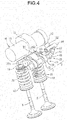
- the rocker arm 9 is formed by a plurality of members, as shown in Figs. 2 to 4 .
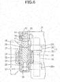
- the plurality of members include a first rocker arm 25 including a roller 24 that contacts the valve drive cam 12, a second rocker arm 26 arranged at a position adjacent to the first rocker arm 25 in the axial direction of the camshaft 14, and first to third switch pins 27 to 29 (see Figs. 6 and 7 ) configured to selectively connect the first rocker arm 25 and the second rocker arm 26.
- the first rocker arm 25 includes a left arm piece 25c and a right arm piece 25d which are connected by two connecting pieces 25a and 25b (see Fig. 5 ) so as to form a U shape in a front view (see Fig. 2 ).
- One end of the first rocker arm 25 is swingably supported by a rocker shaft 30.
- the rocker shaft 30 is mounted on a support member 31 (see Fig. 1 ) of the cylinder head 6 so as to be parallel to the camshaft 14.
- the swing end of the first rocker arm 25 includes a tubular shaft 32, as shown in Figs. 6 and 7 , and supports the roller 24 via the tubular shaft 32.
- the axis of the tubular shaft 32 is parallel to the axis of the rocker shaft 30.
- the roller 24 is rotatably supported on the tubular shaft 32 by a bearing 33.
- the hollow portion of the tubular shaft 32 extends across the first rocker arm 25 in the axial direction of the camshaft 14.
- the first switch pin 27 is movably fitted in the hollow portion.
- the hollow portion of the tubular shaft 32 will be referred to as a first pin hole 34 hereinafter.
- the length of the first switch pin 27 equals the length of the first pin hole 34.
- the first switch pin 27 can be either longer or shorter than the first pin hole 34 as long as it can avoid fitting in a pin hole that comes next to the first switch pin 27 in a non-connected state.
- a spring member 35 for return is provided between the cylinder head 6 and the connecting pieces 25a and 25b that connect the left arm piece 25c and the right arm piece 25d as the swing ends of the first rocker arm 25 so as to form a U shape in the front view, as shown in Figs. 1 and 2 .
- the spring member 35 biases the first rocker arm 25 in a direction in which the roller 24 is pushed against the valve drive cam 12. For this reason, when pushed by the valve drive cam 12, the first rocker arm 25 swings against the spring force of the spring member 35.
- the second rocker arm 26 includes a first arm main body 26a and a second arm main body 26b which are located on both sides of the first rocker arm 25, and a connecting piece 26c that connects the swing ends of the first arm main body 26a and the second arm main body 26b.
- the first arm main body 26a and the second arm main body 26b each have one end swingably supported by the rocker shaft 30.
- the connecting piece 26c is formed into a shape extending in the axial direction of the camshaft 14.
- Pushing portions 36 configured to push the shims 19 of the intake valves 4 or the exhaust valves 5 are formed at two ends of the connecting piece 26c in the longitudinal direction.
- the second rocker arm 26 simultaneously pushes the two intake valves 4 or exhaust valves 5 per cylinder.
- a second pin hole 37 is formed in the middle of the first arm main body 26a.
- a third pin hole 38 is formed in the middle of the second arm main body 26b.
- the second pin hole 37 and the third pin hole 38 extend across the first arm main body 26a and the second arm main body 26b in the axial direction of the camshaft 14.
- the distance between the axis of the rocker shaft 30 and the center line of the second pin hole 37 and the third pin hole 38 matches the distance between the axis of the rocker shaft 30 and the center line of the first pin hole 34 of the first rocker arm 25.
- the first pin hole 34, the second pin hole 37, and the third pin hole 38 are located on the same axis in a state in which the swing angle of the first rocker arm 25 and the swing angle of the second rocker arm 26 are predetermined angles.
- the predetermined angles are angles made when the intake valve 4 or the exhaust valve 5 is kept closed. For this reason, when the valve lift amount of the intake valve 4 or the exhaust valve 5 is 0, the second pin hole 37 and the third pin hole 38 are located on the same axis as the first pin hole 34.
- the hole diameter of the second pin hole 37 and the third pin hole 38 matches the hole diameter of the first pin hole 34.
- the second switch pin 28 is movably fitted in the second pin hole 37.
- a spring member 39 that biases the second switch pin 28 toward the first rocker arm 25 is provided in the second pin hole 37.
- the third switch pin 29 is movably fitted in the third pin hole 38.
- the length of the third switch pin 29 equals the length of the third pin hole 38.
- the third switch pin 29 can be either longer or shorter than the third pin hole 38 as long as it can avoid fitting in a pin hole that comes next to the third switch pin 29 in a non-connected state.
- An end of the third switch pin 29 on the opposite side of the first rocker arm 25 faces a pushing element 41 of the drive unit 23 (to be described later).
- the drive unit 23 has a function of pushing the third switch pin 29 toward the first rocker arm 25 using the pushing element 41.
- the connecting positions are positions at which the first switch pin 27 and the second switch pin 28 are located across the first rocker arm 25 and the second rocker arm 26.
- the first to third switch pins 27 to 29 constitute "some of components which constitute a valve gear system from the valve drive cam to the rocker arm" in the present invention.
- the drive unit 23 of the switching mechanism 3 is formed by combining a plurality of members, and provided at a position adjacent to the rocker arm 9 in the axial direction of the rocker shaft 30, as shown in Figs. 3 and 4 .
- the drive unit 23 shown in Figs. 2 to 5 only the members that operate are illustrated for easy understanding of the structure.
- the pushing element 41 that transmits power from the drive unit 23 to the switching unit 21 is formed into a columnar shape and movably fitted in a shaft hole 42 of the support member 31.
- the support member 31 includes a base 43 through which the rocker shaft 30 extends, and a housing 44 for a drive unit, which projects from the base 43.
- the shaft hole 42 is formed in the housing 44.
- One end of the pushing element 41 which is opposite to the third switch pin 29 is formed into a disc shape having a predetermined size.
- the end face at this end which is opposite to the third switch pin 29 is formed flat such that it can swing integrally with the second arm main body 26b in a state in which the third switch pin 29 contacts the end face.
- This end has a such a size that always faces the third switch pin 29 swinging integrally with the second arm main body 26b.
- a drive lever 45 (to be described later) of the drive unit 23 is pivotally connected to the pushing element 41 via a connecting pin 46.
- the pushing element 41 moves forward or backward with respect to the second arm main body 26b. For this reason, the pushing element 41 reciprocally moves between an advance position shown in Fig. 7 and a retreat position shown in Fig. 6 .
- a plurality of concave portions 47 are formed in the outer surface of the pushing element 41.
- the concave portions 47 are formed into a shape capable of engaging with a ball 48 and arranged in the axial direction of the pushing element 41.
- the ball 48 is held in the housing 44 and pushed against the pushing element 41 by the spring force of a compression coil spring 49 so as to engage with the concave portion 47.
- the pushing element 41 is temporarily held at the above-described advance position or retreat position by engaging the ball 48 with the concave portion 47.
- the drive lever 45 connected to the pushing element 41 is fixed to one end of a pivot shaft 51 (to be described later).
- the drive lever 45 swings in synchronism with the pivotal operation of the pivot shaft 51.
- the pushing element 41 moves in the axial direction of the camshaft 14 and moves to the advance position or the retreat position.
- the drive lever 45 and the above-described pushing element 41 constitute a "transmission mechanism" of the invention described in claim 2.
- the pivot shaft 51 is located at a position where the pivot shaft 51 overlaps the rocker shaft 30 when viewed from the axial direction of the camshaft 14, as shown in Fig. 5 , and faces the cam face of the synchronous cam 13 across the constituent members of the drive unit 23 (to be described later), as shown in Figs. 2 and 3 .
- the pivot shaft 51 is pivotally supported by the housing 44.
- a first projecting piece 52 and a second projecting piece 53 are provided at the other end of the pivot shaft 51.
- the first projecting piece 52 projects from the pivot shaft 51 in a direction perpendicular to the axial direction of the pivot shaft 51.
- the second projecting piece 53 projects from the pivot shaft 51 in another direction opposite to the first projecting piece 52.
- the pivot shaft 51 is mounted in the housing 44 in a state in which the first projecting piece 52 and the second projecting piece 53 are arranged in the axial direction of the camshaft 14.
- the first projecting piece 52 and the second projecting piece 53 are stored in a space S formed in the housing 44.
- the cam face 59 is formed from a steep slope portion 59a and a gentle slope portion 59b.
- the steep slope portion 59a is formed on the base side of each of the first and second projecting pieces 52 and 53.
- the gentle slope portion 59b is formed on the projecting end side of each of the first and second projecting pieces 52 and 53.
- the steep slope portion 59a of the first projecting piece 52 and the steep slope portion 59a of the second projecting piece 53 form the inner wall of a concave portion 60 capable of storing the slide pin 55 (to be described later).
- the concave portion 60 is formed by the two steep slope portions 59a and part of the pivot shaft 51.
- an axis C1 of the pivot shaft 51 and an axis C2 of the slide pin 55 are located on the same plane P.
- the first projecting piece 52 and the second projecting piece 53 are located so as to be almost symmetrical with respect to the plane P.
- the cam follower 22 at a pushing end position is indicated by a solid line
- the cam follower 22 at a pushing start position is indicated by an alternate long and two short dashed line.
- the steep slope portion 59a of the first projecting piece 52 and the steep slope portion 59a of the second projecting piece 53 constitute a "cam face" of the invention described in claim 7.
- the cam follower 22, a moving member 54, and the slide pin 55 are provided between the synchronous cam 13 and the first projecting piece 52 and the second projecting piece 53.
- the cam follower 22 is formed into a columnar shape and supported by the housing 44 so as to be movable in the first directions that is the directions to move close to or move away from the axis of the camshaft 14.
- the cam follower 22 reciprocally moves between the pushing start position (see Fig. 10 ) in which the nose portion 13b of the synchronous cam 13 pushes one end face (the end face which is opposite to the synchronous cam 13) and the pushing end position (see Fig. 8 ) in which the pushing by the synchronous cam 13 ends.
- the period when the nose portion 13b of the synchronous cam 13 pushes the cam follower 22 is the period when the roller 24 of the first rocker arm 25 contacts the circular base portion 12a of the valve drive cam 12 (the period when the intake valves 4 or the exhaust valves 5 are kept closed), in other words, the period when the driving force to drive the intake valves 4 or the exhaust valves 5 is not transmitted to the first to third switch pins 27 to 29 of the switching mechanism 3.
- the moving member 54 arranged between the cam follower 22 and the first projecting piece 52 and the second projecting piece 53 is formed into a columnar shape long in the second directions perpendicular to the above-described first directions and supported by the housing 44 so as to be movable in the second directions.
- the second directions are the directions parallel to the axis of the camshaft 14.
- the above-described pivot shaft 51 is arranged at a position opposite to the cam follower 22 across the moving member 54 and supported by the housing 44 so as to be pivotal about an axis extending in a direction perpendicular to the first directions and the second directions.
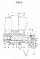
- a cylinder hole 56 formed from a non-through hole extending in the second directions from one side of the housing 44 is formed in the housing 44.
- the moving member 54 is formed into a columnar shape and slidably fitted in the cylinder hole 56.
- One end of the cam follower 22 faces the central portion of the cylinder hole 56 in the axial direction.
- the cylinder hole 56 communicates with the space S that stores the first projecting piece 52 and the second projecting piece 53.
- An oil passage 57 is connected to a bottom portion 56a located in the innermost place of the cylinder hole 56.
- the oil passage 57 forms part of an actuator 58 that drives the moving member 54.
- the actuator 58 includes a hydraulic device 62 with a piston 61 provided at one end of the moving member 54, and a spring member 63 that biases the other end of the moving member 54 to the side of the one end.
- the actuator 58 drives the moving member 54 to one direction or the other direction of the second directions.
- the actuator 58 according to this embodiment corresponds to an "actuator" of the invention described in claim 3.
- the hydraulic device 62 includes a hydraulic pump that is driven by the engine 2 or an electric motor and discharges hydraulic oil, and a switching valve provided between the hydraulic pump and the cylinder hole 56 of the switching mechanism 3.
- the switching valve is automatically or manually operated to switch between a form in which an oil pressure is supplied to the cylinder hole 56 and a form in which the oil pressure in the cylinder hole 56 disappears.
- the spring member 63 that biases the other end of the moving member 54 is formed from a compression coil spring and inserted between the other end of the moving member 54 and a plug member 66 that closes one end of the cylinder hole 56, as shown in Fig. 8 .
- the moving member 54 can reciprocally move between the plug member 66 and the bottom portion 56a of the cylinder hole 56.
- the moving member 54 moves to the side of the plug member 66 against the spring force of the spring member 63.
- the oil pressure of the hydraulic device 62 disappears, the moving member 54 is moved to the side of the bottom portion 56a of the cylinder hole 56 by the spring force of the spring member 63.
- the concave grooves 54a extend by a predetermined length in the second directions on the outer surface of the moving member 54.
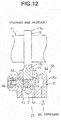
- the predetermined length is a length that allows the cam follower 22 to enter the concave grooves 54a even when the moving member 54 is located at either of terminating positions on the side of the bottom portion 56a and on the side of the plug member 66, as shown in Figs. 8 and 12 .
- the concave grooves 54a are formed on one side and the other side of the moving member 54 in the radial direction.
- the bottom surface of each concave groove 54a is formed flat.
- the slide pin 55 is formed into a columnar shape thinner than the cam follower 22 and supported by the moving member 54 to be movable in the first directions so as to extend through the central portion of the moving member 54 along the first directions.
- One end face of the slide pin 55 can always contact the other end face of the cam follower 22 during the process of moving the moving member 54 from one end in the cylinder hole 56 to the other end.
- the moving member 54 moves in one direction of the second directions (to the side of the bottom portion 56a of the cylinder hole 56), the other end face of the slide pin 55 faces the first projecting piece 52.
- the moving member 54 moves in the other direction of the second directions (to the side of the plug member 66), the other end face of the slide pin 55 faces the second projecting piece 53, as shown in Fig. 10 .
- the cam follower 22 presses the slide pin 55 in a state in which the other end face of the slide pin 55 faces the first projecting piece 52 or the second projecting piece 53, the first projecting piece 52 or the second projecting piece 53 is pushed by the slide pin 55.
- the length of the slide pin 55 is set to push the first projecting piece 52 or the second projecting piece 53 in a direction to move away from the cam follower 22 when the cam follower 22 is pushed by the synchronous cam 13 and moves to the pressing end position.
- the one projecting piece that has received the pushing force makes the pivot shaft 51 pivot to one side where the projecting piece is located (clockwise in Fig. 8 ).
- the first projecting piece 52 and the second projecting piece 53 swing in a so-called seesaw motion about the pivot shaft 51. For this reason, the one projecting piece (the first projecting piece 52 in Fig. 8 ) pushed by the slide pin 55 tilts in a direction in which the distal end moves away from the cam follower 22. At this time, the other projecting piece (the second projecting piece 53 in Fig. 8 ) tilts in a direction in which the distal end moves close to the cam follower 22.
- the other projecting piece tilts so as to gradually move close to the cam follower 22 from the pivot shaft 51 to the distal end.
- the slide pin 55 that has pushed the one projecting piece moves toward the other projecting piece (to the side where the plug member 66 is located in Fig. 8 ) together with the moving member 54, the other projecting piece that has thus tilted functions as a return cam 67 that pushes the slide pin 55 to the side of the cam follower 22.
- the other projecting piece functions as the return cam 67
- the slide pin 55 contacts the above-described cam face 59, and the moving direction of the slide pin 55 changes. This means that the cam face 59 actually functions as the return cam.
- the time when the moving member 54 moves is the time when the slide pin 55 is not pushed by the cam follower 22. This is because when pushed by the cam follower 22, the slide pin 55 cannot move to the side of the cam follower 22 along the return cam 67. For this reason, the moving member 54 stands by without moving until two conditions to be described later are met, and moves after the two conditions are met.
- the first condition of the two conditions is that an oil pressure or the spring force of the spring member 63 is applied.
- the second condition is that the cam follower 22 faces the circular base portion 13a of the synchronous cam 13.
- valve gear 1 for the engine 2 having the above-described arrangement will be described next in detail with reference to Figs. 8 to 16 .
- An operation performed when the switching mechanism 3 switches the operation form of the engine 2 from the full cylinder operation form to the partial cylinder operation form will be described first.
- the switching mechanism 3 is in the state shown in Figs. 8 and 9 . That is, the moving member 54 of the drive unit 23 is pushed by the spring force of the spring member 63 and moved to one end side (the side of the bottom portion 56a of the cylinder hole 56).
- the drive lever 45 and the pivot shaft 51 are rotated clockwise in Figs. 8 and 9 .
- the pushing element 41 is located at the retreat position, and the first to third switch pins 27 to 29 are located at the connecting positions.
- the first rocker arm 25 and the second rocker arm 26 are connected and integrally swing.
- the valve gear 1 for the engine 2 starts operating when the rotation of a crankshaft (not shown) is transmitted to the camshaft 14.
- a crankshaft (not shown)
- the valve drive cam 12 and the synchronous cam 13 rotate.
- the rotation of the valve drive cam 12 is transmitted from the first rocker arm 25 to the second rocker arm 26 via the first switch pin 27 and the second switch pin 28 to drive the intake valves 4 or the exhaust valves 5.
- the synchronous cam 13 idles without pushing the cam follower 22 because the cam follower 22 is located at the pushing end position.
- an oil pressure is supplied to the piston 61 manually or automatically by the hydraulic device 62 of the actuator 58 in an arbitrary period.
- the moving member 54 is biased by the oil pressure to the other end side (the left side or the side of the plug member 66 in Fig. 8 ) that is the opposite side of the current position in Fig. 8 .
- the oil pressure thus acts on the moving member 54
- the moving member 54 moves to the side of the plug member 66 against the spring force of the spring member 63.
- the slide pin 55 strikes the cam face 59 of the second projecting piece 53.
- the slide pin 55 needs to move upward along the steep slope portion 59a of the cam face 59 and move in the direction to push the cam follower 22.
- the slide pin 55 is pushed against the steep slope portion 59a and slips, and moves in the direction to move close to the synchronous cam 13, as indicated by an alternate long and two short dashed line A in Fig. 16 .
- the second projecting piece 53 is never pushed by the slide pin 55 and tilts. This is because the ball 48 engages with the concave portion 47, and the pivotal motion of the pivot shaft 51 is regulated. For this reason, the pushing element 41 is held at the retreat position, and the first to third switch pins 27 to 29 are held at the connecting positions.
- the slide pin 55 moves to a position indicated by an alternate long and two short dashed line C via a position indicated by an alternate long and two short dashed line B in Fig. 16 .
- the position indicated by the alternate long and two short dashed line B is the position at which the slide pin 55 contacts the gentle slope portion 59b or the position at which the axis C1 of the pivot shaft 51 and the axis C2 of the slide pin 55 are arranged on the same plane P.
- the position indicated by the alternate long and two short dashed line C is the position at which the cam follower 22 returns to the moving start position.
- the camshaft 14 is rotating even when the moving member 54 and the slide pin 55 are moving as described above.
- the nose portion 13b of the synchronous cam 13 may push the cam follower 22.
- the slide pin 55 is pushed by the cam follower 22 and slides down along the steep slope portion 59a, and the moving member 54 retreats against the oil pressure.
- the cam follower 22 is pushed again by the nose portion 13b of the synchronous cam 13 that is continuously rotating.
- the time when the cam follower 22 is pushed by the nose portion 13b of the synchronous cam 13 is the time when the intake valves 4 or the exhaust valves 5 are kept closed or the time when the first to third switch pins 27 to 29 of the switching mechanism 3 can move.
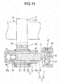
- the cam follower 22 is pushed by the nose portion 13b of the synchronous cam 13 and thus moves to the pushing end position, as shown in Fig. 12 .
- the oil pressure supply by the hydraulic device 62 of the actuator 58 is manually or automatically stopped in an arbitrary period.
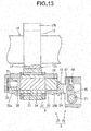
- the moving member 54 is moved to the side of the bottom portion 56a of the cylinder hole 56 by the spring force of the spring member 63 when the circular base portion 13a of the synchronous cam 13 faces the cam follower 22, as shown in Fig. 14 .
- the slide pin 55 slips while being pushed against the tilted first projecting piece 52, and moves in the direction to move close to the synchronous cam 13.
- the cam follower 22 is returned from the pushing end position to the pushing start position.
- the slide pin 55 moves in the same direction as the cam follower 22 and is pushed against the first projecting piece 52.
- the pivot shaft 51 rotates clockwise from the position shown in Fig. 14 to the position shown in Fig. 8 . Note that at this time as well, the ball 48 leaves one concave portion 47 and enters the other concave portion 47.
- the drive lever 45 swings clockwise from the position shown in Fig. 15 to the position shown in Fig. 9 .
- the time when the drive lever 45 swings in this way is the time when the intake valves 4 or the exhaust valves 5 are kept closed, and the driving force is not transmitted to the first arm main body 26a and the second arm main body 26b (the time when the movement of the first to third switch pins 27 to 29 is not regulated).
- the switching mechanism 3 when the intake valves 4 or the exhaust valves 5 are kept closed, and the first to third switch pins 27 to 29 of the switching mechanism 3 can move, the switching mechanism 3 is driven by pushing force generated when the synchronous cam 13 pushes the cam follower 22. Hence, since the time when the intake valves 4 or the exhaust valves 5 are kept closed, and the first to third pin holes 34, 37, and 38 are located on the same axis synchronizes with the time when the first to third switch pins 27 to 29 move, the first to third switch pins 27 to 29 always smoothly move in an optimum period.
- valve gear for an engine which can reliably prevent damage to components and implement a reliable operation of switching the drive form of an intake valve or an exhaust valve.
- One of the first projecting piece 52 and the second projecting piece 53 according to this embodiment which has the slide pin 55 intervening with respect to the cam follower 22, receives pushing force, via the slide pin 55, from the cam follower 22 pushed by the synchronous cam 13, thereby rotating the pivot shaft 51 to one side where the one projecting piece is located.
- the other projecting piece functions as the return cam 67 that pushes the slide pin 55 to the side of the cam follower 22 and returns the cam follower 22 to the pushing start position when the slide pin 55 that has pushed the one projecting piece moves toward the other projecting piece together with the moving member 54.
- the cam follower 22 can be returned to the pushing start position using the first and second projecting pieces 52 and 53 that convert the reciprocating motion of the cam follower 22 into a pivotal motion. For this reason, since a mechanism configured to exclusively return the cam follower 22 to the pushing start position is unnecessary, it is possible to reduce the number of components and form a compact drive unit 23.
- the actuator 58 includes the hydraulic device 62 with the piston 61 provided at one end of the moving member 54, and the spring member 63 that biases the other end of the moving member 54 to the one end side.
- the moving member 54 moves in the other direction (to the side of the plug member 66) of the second directions against the spring force of the spring member 63.
- the moving member 54 moves in one direction (to the side of the bottom portion 56a of the cylinder hole 56) in the second directions by the spring force of the spring member 63. That is, the moving member 54 reciprocally moves as the state in which the oil pressure is supplied and the state in which the oil pressure disappears are alternately repeated.
- the hydraulic pump or switching valve of the hydraulic device 62 can be arranged at a position apart from the switching mechanism 3. For this reason, as compared to an arrangement in which the switching operation of the switching unit 21 is mechanically controlled by, for example, a solenoid or the like, the degree of freedom of layout of the switching mechanism 3 is high.
- the concave portion 60 capable of storing the distal end of the slide pin 55 pushed by the cam follower 22 and moved is formed between the first projecting piece 52 and the second projecting piece 53 according to this embodiment.
- the inner wall of the concave portion 60 is formed by the cam faces 59 (steep slope portions 59a) that function as the return cam 67 in the first projecting piece 52 and the second projecting piece 53.
- the rocker arm 9 includes the first rocker arm 25 and the second rocker arm 26.
- the first rocker arm 25 is pushed by the valve drive cam 12 and swings.
- the second rocker arm 26 is swingably provided at a position adjacent to the first rocker arm 25 in the axial direction of the camshaft 14, and the pushing portions 36 configured to push the intake valves 4 or the exhaust valves 5 are provided at the swing ends.
- the first to third pin holes 34, 37, and 38 extending in the axial direction of the camshaft 14 are formed across the members.
- the members driven by the drive unit 23 are the first to third switch pins 27 to 29 movably fitted in the first to third pin holes 34, 37, and 38 and arranged in the axial direction of the camshaft 14.
- the first to third switch pins 27 to 29 move to connecting positions across the first rocker arm 25 and the second rocker arm 26 and connect the two rocker arms 9.
- the first to third switch pins 27 to 29 move from the positions across the first rocker arm 25 and the second rocker arm 26 and cancel the connected state between the two rocker arms 25 and 26.
- valve gear for an engine which can correctly switch between the first drive form in which the intake valves 4 or the exhaust valves 5 are driven and the second drive form in which the intake valves 4 or the exhaust valves 5 are stopped.
- the engine 2 is a multi-cylinder (four-cylinder) engine.
- the first drive form is a drive form in which the intake valves 4 or the exhaust valves 5 are driven as usual.
- the second drive form is a drive form in which the intake valves 4 or the exhaust valves 5 keep the closed state.
- the switching mechanism 3 according to this embodiment switches the drive form of the intake valves 4 or the exhaust valves 5 in cylinders that selectively put at rest.
- valve gear for an engine which can selectively put some of a plurality of cylinders at rest.
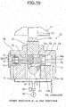
- the actuator provided in the drive unit of the switching mechanism can be configured as shown in Figs. 18 and 19 .
- the same reference numerals as those of the members described with reference to Figs. 1 to 17 denote the same or similar members in Figs. 18 and 19 , and a detailed description thereof will appropriately be omitted.
- a hydraulic device according to this embodiment is a hydraulic device described in claim 4.
- An actuator 58 shown in Fig. 18 includes a hydraulic device 71.
- the hydraulic device 71 according to this embodiment includes a piston (to be referred to as a first piston hereinafter) 61 provided at one end of a moving member 54 and a second piston 72 provided at the other end of the moving member 54.
- the moving member 54 When an oil pressure is applied to the second piston 72, the moving member 54 according to this embodiment moves to the side of a bottom portion 56a of a cylinder hole 56, as shown in Fig. 18 .
- the moving member 54 moves to the side of a plug member 66, as shown in Fig. 19 .
- the moving member 54 moves in the second directions when a cam follower 22 faces a circular base portion 13a of a synchronous cam 13.
- a compression coil spring 73 configured to bias the moving member 54 in one direction of the second directions is provided between the second piston 72 and the plug member 66.
- the compression coil spring 73 constitutes a "spring member" of the invention described in claim 5, and is provided to avoid uncontrollability caused by cutoff of the oil pressure supply.
- the spring load of the compression coil spring 73 is set to be lower than that of the spring member 63 used in the first embodiment because the purpose is different from that of the spring member 63.
- the first drive form is the full cylinder operation form which is a drive form on a side advantageous in starting the engine 2 or a drive form employed at the time of idling.
- the bottom portion 56a of the cylinder hole 56 communicates with a switching valve 65 via a first oil passage 74.
- the other end (a side end of the plug member 66) of the cylinder hole 56 communicates with the switching valve 65 via a second oil passage 75.
- the switching valve 65 is configured to automatically or manually perform a switching operation to implement two forms to be described later.
- the first form is a form in which the oil pressure supplied from a hydraulic pump 64 is supplied to the first oil passage 74, and the oil pressure in the second oil passage 75 disappears.
- the second form is a form in which the oil pressure supplied from the hydraulic pump 64 is supplied to the second oil passage 75, and the oil pressure in the first oil passage 74 disappears.
- the first oil passage 74 and the second oil passage 75 connect the cylinder holes 56 of the switching mechanisms 3 for the intake valves and the exhaust valves of all cylinders with the switching mechanisms 3 to the switching valve 65, although not illustrated.
- the moving member 54 moves in the other direction (to the side of the plug member 66) in the second directions when the oil pressure is applied to the first piston 61, and moves in one direction (to the side of the bottom portion 56a of the cylinder hole 56) of the second directions when the oil pressure is applied to the second piston 72.
- the degree of freedom in setting the magnitude of the oil pressure becomes higher than in a case in which the first embodiment with the spring member 63 is employed.
- the moving member 54 need not be pushed against large spring force like that of the spring member 63 according to the first embodiment, and therefore, the oil pressure can accordingly be set to be lower. This means that the normal rotation speed of the hydraulic pump 64 is relatively low, and the switching operation can be performed even if the rotation speed of the engine 2 is low.
- the valve gear 1 includes the compression coil spring 73 that biases the moving member 54 to one direction in the second directions.
- the direction in which the compression coil spring 73 biases the moving member 54 is the direction in which the drive form is switched to the drive form on the side advantageous in starting the engine out of the first drive form and the second drive form.
- the transmission mechanism provided in the switching mechanism can be configured as shown in Figs. 20 to 22 .
- the same reference numerals as those of the members described with reference to Figs. 1 to 19 denote the same or similar members in Figs. 20 to 22 , and a detailed description thereof will appropriately be omitted.
- the transmission mechanism of a switching mechanism 3 shown in Figs. 20 to 22 includes a drive lever 45 that is fixed to one end of a pivot shaft 51 and pivots integrally with the pivot shaft 51, a pushing element 41 facing a third switch pin 29, and a connecting lever 81 that connects the pushing element 41 to the drive lever 45.
- the drive lever 45 constitutes a "first lever” of the invention described in claim 6.
- the connecting lever 81 constitutes a "second lever” of the invention described in claim 6.
- the connecting lever 81 is pivotally supported by a support shaft 82 on a housing 44 (not shown).
- the support shaft 82 extends through the central portion of the connecting lever 81 in the longitudinal direction, and is fixed to the housing 44.
- the axis of the support shaft 82 is parallel to the axis of the pivot shaft 51.
- One end of the connecting lever 81 is pivotally connected to the pushing element 41 via a first connecting shaft 81a, and is connected to some of the components which constitute the above-described valve gear system via the pushing element 41.
- the other end of the connecting lever 81 is pivotally connected to the pivotal end of the drive lever 45 via a second connecting shaft 81b.
- the axes of the first connecting shaft 81a and the second connecting shaft 81b are parallel to the axes of the pivot shaft 51 and the support shaft 82.
- a length L1 of the connecting lever 81 on one end side equals a length L2 on the other end side.
- the length L1 is the distance between the axis of the support shaft 82 and the axis of the first connecting shaft 81a.
- the length L2 is the distance between the axis of the support shaft 82 and the axis of the second connecting shaft 81b.
- a click mechanism 83 is connected to the other end of the pivot shaft 51 to define the magnitude of pushing force necessary to rotate the pivot shaft 51.
- the click mechanism 83 includes a pressure receiving member 84 fixed to the pivot shaft 51, and a ball 85 held by the housing 44 (not shown). Two concave portions 86 arranged in the pivotal direction of the pivot shaft 51 are formed in the pressure receiving member 84. The ball 85 is pushed by a compression coil spring 87 and engages with one concave portion 86.
- the distance between the pivot shaft 51 and a camshaft 14 becomes longer by the length of the connecting lever 81, as compared to a case in which the arrangement shown in Fig. 1 is employed.
- the pivot shaft 51 can be arranged at a position apart from a rocker shaft 30. It is therefore possible to raise the degree of freedom of layout of a drive unit 23 and facilitate an operation of assembling the members of the drive unit 23 to the housing 44.
- the length L1 of the connecting lever 81 equals the length L2 on the other end side. If L1 > L2, the operation of the drive lever 45 is enlarged by a lever ratio corresponding to the ratio of the length L1 to the length L2 and transmitted to the pushing element 41.
- the operation amount of the drive lever 45 depends on the operation amount of the cam follower 22 pushed by a nose portion 13b of the synchronous cam 13 and moved to rotate the pivot shaft 51. When the operation is enlarged by the lever ratio, the pushing element 41 can be moved sufficiently largely without making the nose portion 13b of the synchronous cam 13 so high.
- a valve gear for an engine according to the present invention can be configured as shown in Figs. 23 to 26 .
- the same reference numerals as those of the members described with reference to Figs. 1 to 22 denote the same or similar members in Figs. 23 to 26 , and a detailed description thereof will appropriately be omitted.
- a valve gear for an engine according to this embodiment constitutes the inventions described in claims 9 and 13.
- the valve gear for an engine according to this embodiment is different from the valve gears according to the above-described embodiments in the arrangements of a camshaft 14 and a switching unit 21 of a switching mechanism 3, and the rest of the arrangement is the same.
- a valve gear 91 for an engine 2 shown in Fig. 23 includes two types of valve drive cams to employ two types of drive forms.
- the two types of valve drive cams are a first cam 92 and second cams 93, which have different valve lift amounts of intake valves 4 or exhaust valves 5.
- the first cam 92 and the second cams 93 are arranged in the axial direction of a camshaft main body 11.
- the second cams 93 according to this embodiment are provided on both sides of the first cam 92.
- the first cam 92 and the second cam 93 have circular base portions 92a and 93a and nose portions 92b and 93b, respectively.
- the outer diameter of the circular base portion 92a of the first cam 92 equals the outer diameter of the circular base portion 93a of the second cam 93.
- the nose portion 92b of the first cam 92 is formed into a shape capable of obtaining a larger valve lift amount of the intake valves 4 or the exhaust valves 5 than the valve lift amount of the nose portion 93b of the second cam 93.
- a rocker arm 9 used in the valve gear 1 includes a first rocker arm 25 that is pushed by the first cam 92 and swings, and a second rocker arm 26 arranged at a position adjacent to the first rocker arm 25 in the axial direction of the camshaft 14.
- the first rocker arm 25 includes, at its swing end, a roller 24 configured to contact the first cam 92 and rotate, and is swingably supported by a rocker shaft 30 (not shown), like the first rocker arm 25 shown in Figs. 6 and 7 .
- the second rocker arm 26 includes a first arm main body 26a and a second arm main body 26b which are located on both sides of the first rocker arm 25, and a connecting piece (not shown) that connects the swing ends of the first arm main body 26a and the second arm main body 26b, like the second rocker arm 26 shown in Figs. 6 and 7 .
- the first arm main body 26a and the second arm main body 26b are located at positions where they can be pushed by the second cams 93, and swingably supported by the rocker shaft 30.
- the second rocker arm 26 includes rollers 94 configured to contact the second cams 93 and rotate, and pushing portions 36 configured to push the intake valves 4 or the exhaust valves 5.
- the pushing portions 36 are provided at the swing ends of the second rocker arm 26.
- first rocker arm 25 and the second rocker arm 26 are selectively connected by the same connecting structure as that shown in Figs. 6 and 7 .
- first to third pin holes 34, 37, and 38 extending in the axial direction of the camshaft 14 are formed across these rocker arms.
- First to third switch pins 27 to 29 are movably fitted in first to third pin holes 34, 37, and 38.
- the first to third switch pins 27 to 29 move to non-connecting positions at which the first to third switch pins 27 to 29 are not located across the first rocker arm 25 and the second rocker arm 26 to set the first rocker arm 25 and the second rocker arm 26 in a non-connected state.
- the first to third switch pins 27 to 29 move to connecting positions at which the first to third switch pins 27 to 29 are located across the first rocker arm 25 and the second rocker arm 26 to set the first rocker arm 25 and the second rocker arm 26 in a connected state.
- the first to third switch pins 27 to 29 constitute "some of components which constitute a valve gear system from the valve drive cam to the rocker arm" in the present invention.
- the first rocker arm 25 is pushed by the first cam 92 whose valve lift amount is relatively large. For this reason, when the camshaft 14 rotates in a state in which the first to third switch pins 27 to 29 are located at the connecting positions (see Fig. 25 ), the rollers 94 of the second rocker arm 26 separate from the second cams 93, as shown in Fig. 26 . At this time, the valve lift amount of the intake valves 4 or the exhaust valves 5 is larger than in a case in which the second rocker arm 26 is pushed by the second cams 93 and swings.
- valve gear for an engine which can correctly switch between the first drive form in which the valve lift amount of the intake valves 4 or the exhaust valves 5 is large and the second drive form in which the valve lift amount of the intake valves 4 or the exhaust valves 5 is small.
- the drive form is preferably switched in all cylinders.
- the switching mechanisms 3 are provided in all cylinders.
- the hydraulic device of the switching mechanism 3 in this case, the hydraulic device 62 described in the first embodiment or the hydraulic device 71 described in the second embodiment can be used.
- an arrangement that supplies an oil pressure from one hydraulic pump via two switching valves can be employed.
- the two switching valves include a first switching valve that supplies the oil pressure to a cylinder hole 56 of the switching mechanism 3 for an intake valve, and a second switching valve that supplies the oil pressure to the cylinder hole 56 of the switching mechanism 3 for an exhaust valve.
- the switching mechanism 3 is provided on at least one of the side of the intake valves 4 and the side of the exhaust valves 5.
- the switching mechanism 3 can be provided only on the side of the intake valves 4, or the switching mechanism 3 can be provided only on the side of the exhaust valves 5.
- the plurality of drive forms are switched to change the valve lift amount of the intake valves 4, thereby facilitating control of the output, fuel consumption, and exhaust gas amount of the engine 2.
- the plurality of drive forms are switched to change the valve lift amount of the exhaust valves 5, thereby similarly facilitating control of the output, fuel consumption, and exhaust gas amount.
- valve gear 91 when the valve gear 91 according to this embodiment is mounted, the degree of freedom in controlling the operation of the engine 2 becomes high, and a high-performance engine can be obtained.
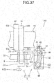
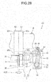
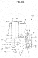
- a valve gear for an engine according to the present invention can be configured as shown in Figs. 27 to 30 .
- the same reference numerals as those of the members described with reference to Figs. 1 to 26 denote the same or similar members in Figs. 27 to 30 , and a detailed description thereof will appropriately be omitted.
- a valve gear for an engine according to this embodiment constitutes the invention described in claim 10.
- the valve gear for an engine according to this embodiment is different from the valve gears according to the above-described embodiments in the arrangements of a camshaft 14 and a switching unit 21 of a switching mechanism 3, and the rest of the arrangement is the same.
- a valve gear 101 shown in Fig. 27 includes a first cam 92 and a second cam 93, which have different valve lift amounts of intake valves 4 or exhaust valves 5, to employ two types of drive forms.
- the first cam 92 and the second cam 93 are the same as those shown in Fig. 23 .
- the second cam 93 according to this embodiment is arranged on only one side of the first cam 92 and is in contact with the first cam 92.
- a rocker arm 9 used in the valve gear 101 is supported by a rocker shaft 30 so as to be movable in the axial direction and also swingably supported by the rocker shaft 30.
- a pushing portion 36 configured to push the intake valve 4 or the exhaust valve 5 is provided at the swing end of the rocker arm 9.
- the pushing portion 36 is formed into a shape having a predetermined length in the axial direction of the rocker shaft 30. The length of the pushing portion 36 is equal to or more than the interval (formation pitch) between the first cam 92 and the second cam 93.
- the rocker arm 9 includes a roller 24 configured to contact the first cam 92 or the second cam 93 and rotate, and also includes a connecting piece 102 that projects in the axial direction of the rocker shaft 30.
- the connecting piece 102 is connected to a connecting piece 103 of a drive unit 23.
- the connecting piece 103 is pivotally connected to a drive lever 45 of the drive unit 23 and movably supported by a housing 44 so as to move back and forth with respect to the rocker arm 9.
- a plurality of concave portions 47 that engage with a ball 48 are formed in the connecting piece 103.
- the rocker arm 9 constitutes "some of components which constitute a valve gear system from the valve drive cam to the rocker arm" in the present invention.
- valve gear for an engine which can correctly switch between the first drive form in which the valve lift amount of the intake valve 4 or the exhaust valve 5 is relatively large and the second drive form in which the valve lift amount of the intake valve 4 or the exhaust valve 5 is relatively small.
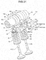
- the valve gear including the switching unit for moving the rocker arm can be configured as shown in Figs. 31 to 34 .
- the same reference numerals as those of the members described with reference to Figs. 1 to 30 denote the same or similar members in Figs. 31 to 34 , and a detailed description thereof will appropriately be omitted.
- the camshaft 14 of the valve gear 101 includes two cam portions 104 per cylinder.
- a synchronous cam 13 according to this embodiment is provided between the two cam portions 104.
- Each of the cam portions 104 includes the first cam 92 and the second cam 93, which have different valve lift amounts of the intake valves 4 or the exhaust valves 5.
- the second cam 93 according to this embodiment is formed into a cylindrical shape having the same diameter as a circular base portion 92a of the first cam 92. That is, the second cam 93 has no nose portion.
- the rocker arm 9 shown in Fig. 31 includes a first rocker arm 25, a second rocker arm 26, and a semi-tubular shaft 105 (see Fig. 32 ).
- the first rocker arm 25 drives one of the two intake valves 4 or the two exhaust valves 5 per cylinder.
- the second rocker arm 26 drives the other of the two intake valves 4 or the two exhaust valves 5 per cylinder.
- the semi-tubular shaft 105 connects the second rocker arm 26 to the first rocker arm 25.
- the first rocker arm 25, the second rocker arm 26, and the semi-tubular shaft 105 are supported by the rocker shaft 30 to be movable in the axial direction and also pivotally supported by the rocker shaft 30.
- the roller 24 is rotatably provided in the middle of each of the first rocker arm 25 and the second rocker arm 26.
- the roller 24 of the first rocker arm 25 contacts the first cam 92 or the second cam 93 of one of the two cam portions 104 and rotates.
- the roller 24 of the second rocker arm 26 contacts the first cam 92 or the second cam 93 of the other cam portion 104 and rotates.
- a pushing portion 36 configured to push a shim 19 of the intake valve 4 or the exhaust valve 5 is provided at the swing end of each of the first rocker arm 25 and the second rocker arm 26. As shown in Fig. 32 , the pushing portion is formed into a shape having a predetermined length in the axial direction of the rocker shaft 30. The length of the pushing portion 36 is equal to or more than the interval (formation pitch) between the first cam 92 and the second cam 93.
- the semi-tubular shaft 105 is formed into a semi-circular sectional shape fitted on the rocker shaft 30 to be pivotal and movable in the axial direction.
- the two ends of the semi-tubular shaft 105 are connected to the first rocker arm 25 and the second rocker arm 26 by, for example, welding, and the semi-tubular shaft 105 pivots integrally with the first rocker arm 25 and the second rocker arm 26.
- a slider 107 of a semi-cylindrical shape with a connecting piece 106 is fitted between the first rocker arm 25 and the second rocker arm 26, as shown in Fig. 32 .
- the slider 107 is formed into a semi-circular sectional shape fitted on the rocker shaft 30 to be pivotal and movable in the axial direction, and is arranged on the opposite side of the semi-tubular shaft 105 across the rocker shaft 30.
- the two ends of the slider 107 are disconnected from the first rocker arm 25 and the second rocker arm 26 so as not to regulate the swing of the first rocker arm 25 and the second rocker arm 26.
- One end 107a (see Fig.
- the connecting piece 106 is provided at the center of the slider 107 in the axial direction and pivotally connected to the drive lever 45 of the drive unit 23.
- a valve gear for an engine which can correctly switch between the first drive form in which the intake valves 4 or the exhaust valves 5 maintain a closed state and the second drive form in which the intake valves 4 or the exhaust valves 5 are driven as usual.
- the second cam 93 a cam having a nose portion 93b (see Fig. 27 ) can be used.
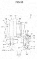
- the valve gear including the switching unit for moving the rocker arm can be configured as shown in Fig. 35 .
- the same reference numerals as those of the members described with reference to Figs. 1 to 34 denote the same or similar members in Fig. 35 , and a detailed description thereof will appropriately be omitted.
- each of the intake camshaft 7 and the exhaust camshaft 8 includes the two cam portions 104 as shown in Fig. 33 . That is, the intake camshaft 7 includes the first cams 92 and the second cams 93, whose valve lift amounts change between the intake valves 4. The exhaust camshaft 8 includes the first cams 92 and the second cams 93, whose valve lift amounts change between the exhaust valves 5.
- the four rocker arms 9 shown in Fig. 35 are swingably supported by the rocker shafts 30 and also supported to be movable in the axial directions of the rocker shafts 30.
- the four rocker arms 9 are connected to the drive lever 45 of the drive unit 23 by a link mechanism 112 (to be described later).
- the roller 24 is provided in the middle of each rocker arm 9. Each roller 24 contacts the first cam 92 or the second cam 93 and rotates, as will be described later.
- Only one drive unit 23 of the switching mechanism 3 according to this embodiment is provided near one of the intake camshaft 7 and the exhaust camshaft 8. That is, one drive unit 23 is provided per cylinder.
- the synchronous cam 13 serving as the power source for the drive unit 23 is provided on the one camshaft.
- the drive unit 23 shown in Fig. 35 is disposed near the intake camshaft 7.
- the drive lever 45 of the drive unit 23 is formed into a shape extending to one side and the other side of the pivot shaft 51.
- the link mechanism 112 is connected to the two ends of the drive lever 45.
- the link mechanism 112 includes a first link 113 that connects two rocker arms 9A for driving the intake valves, a second link 114 that connects two rocker arms 9B for driving the exhaust valves, and a third link 115 that connects the first link 113 and the second link 114.
- the connecting structure 116 is formed from a connecting pin 117 fixed to the first link 113, and a long hole 118 formed in the rocker arm 9A.
- the long hole 118 extends along directions in which the rocker arm 9A swings so the swing of the rocker arm 9A is not regulated by the connecting pin 117.
- the connecting pin 117 is movably fitted in the long hole 118.
- the other end of the first link 113 is connected to the other rocker arm 9A for driving the intake valve via the above-described connecting structure 116, although not illustrated.
- One end of the drive lever 45 is pivotally connected to the other end of the first link 113 via a connecting pin 119.
- the connecting structure 120 is the same as the above-described connecting structure 116, and is formed from a connecting pin 121 fixed to the second link 114, and a long hole (not shown) extending along the swing directions of the rocker arm 9B.
- the other end of the second link 114 is connected to the other rocker arm 9B for driving the exhaust valve via the above-described connecting structure 120.
- the other end of the drive lever 45 is pivotally connected to the other end of the second link 114 via a connecting pin 122.
- the third link 115 is pivotally supported by a cylinder head 6 (not shown) via a support shaft 123.
- the length of the third link 115 equals the length of the drive lever 45.
- the support shaft 123 extends through the central portion of the third link 115 in the longitudinal direction.
- the axis of the support shaft 123 is parallel to the axis of the pivot shaft 51.
- One end of the third link 115 is pivotally connected to one end of the first link 113 via a connecting pin 124.
- the other end of the third link 115 is connected to one end of the second link 114 via a connecting pin 125.
- the axes of the above-described connecting pins 117, 121, 119, 122, 124, and 125 are parallel to the axis of the pivot shaft 51.
- driving force is transmitted from the drive lever 45 of the drive unit 23 to the four rocker arms 9 via the link mechanism 112, and the four rocker arms 9 simultaneously move in the axial directions of the rocker shafts 30.
- switching of the drive form of the intake valves 4 and the exhaust valves 5, which include two valves per cylinder, can be done by one drive unit 23. It is therefore possible to suppress the manufacturing cost low.
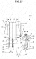
- a valve gear for an engine according to the present invention can be configured as shown in Figs. 36 to 39 .
- the same reference numerals as those of the members described with reference to Figs. 1 to 35 denote the same or similar members in Figs. 36 to 39 , and a detailed description thereof will appropriately be omitted.
- valve gear for an engine constitutes the invention described in claim 11.
- the valve gear is different from the valve gears according to the above-described embodiments in the arrangements of a camshaft 14 and a switching unit 21 of a switching mechanism 3, and the rest of the arrangement is the same.
- a valve gear 131 shown in Fig. 36 includes a first cam 92 and a second cam 93, which have different valve lift amounts of intake valves 4 or exhaust valves 5, to employ two types of drive forms.
- the first cam 92 and the second cam 93 are arranged in the axial direction of a camshaft main body 11.
- the first cam 92 and the second cam 93 are mounted on the camshaft main body 11 via a tubular slider 132.
- the slider 132 is fitted on the outer surface of the camshaft main body 11 by, for example, a spline (not shown) so as to have the camshaft main body 11 inserted into the hollow portion.
- the slider 132 is supported by the camshaft main body 11 to be movable in the axial direction in a state in which the relative movement in the rotation direction is regulated.
- Each of the first cam 92 and the second cam 93 is fixed to the slider 132 so as to have the slider 132 extending through the axial portion.
- An annular plate-shaped flange 133 is provided at one end of the slider 132 in the axial direction.
- the flange 133 is located on the same axis as the slider 132.
- the flange 133 is connected to a connecting member 134 of the switching mechanism 3.
- the connecting member 134 is pivotally connected to a drive lever 45 of a drive unit 23 and movably supported by a housing 44 so as to move back and forth with respect to the first cam 92 and the second cam 93.
- a connecting piece 136 is provided at the distal end of the connecting member 134.
- the connecting piece 136 has a groove 135 in which the above-described flange 133 is slidably fitted.
- a rocker arm 9 according to this embodiment is swingably supported by a rocker shaft 30 in a state in which the movement in the axial direction is regulated.
- a roller 24 configured to contact the first cam 92 or the second cam 93 and rotate is provided in the middle of the rocker arm 9.
- a pushing portion 36 configured to push a shim 19 of the intake valve 4 or the exhaust valve 5 is provided at the swing end of the rocker arm 9.
- the number of intake valves 4 or exhaust valves 5 to be driven by the rocker arm 9 is not restricted by the arrangement of the switching unit 21.
- the rocker arm 9 according to this embodiment can employ an arrangement that drives one intake valve 4 or exhaust valve 5 per cylinder or an arrangement that drives two intake valves 4 or exhaust valves 5 per cylinder.
- first cam 92 and the second cam 93 constitute "some of components which constitute a valve gear system from the valve drive cam to the rocker arm" in the present invention.
- valve gear 131 when the pivot shaft 51 of the switching mechanism 3 rotates in one direction, the second cam 93 contacts the roller 24, and the first cam 92 separates from the roller 24, as shown in Fig. 36 .
- the camshaft 14 rotates in this state, the rocker arm 9 is pushed by the second cam 93 and swings, as shown in Fig. 37 .
- valve gear for an engine which can switch the drive form of the intake valve 4 or the exhaust valve 5 by moving the first cam 92 and the second cam 93.
- the valve gear including the switching unit for moving the first cam and the second cam can be configured as shown in Figs. 40 to 44 .
- the same reference numerals as those of the members described with reference to Figs. 1 to 39 denote the same or similar members in Figs. 40 to 44 , and a detailed description thereof will appropriately be omitted.
- valve gear 131 shown in Fig. 40 the two intake valves 4 or exhaust valves 5 per cylinder are driven by the camshaft 14 and the rocker arms 9.
- the camshaft 14 includes two cam portions 104 per cylinder.
- a synchronous cam 13 is arranged between the cam portions 104.
- a gap d2 (see Fig. 41 ) having a predetermined width is formed between each cam portion 104 and the synchronous cam 13.
- Each of the two cam portions 104 includes the first cam 92 and the second cam 93, which have different valve lift amounts of the intake valves 4 or the exhaust valves 5.
- the length of the synchronous cam 13 according to this embodiment in the axial direction is more than the interval (formation pitch) between the first cam 92 and the second cam 93.
- the second cam 93 is formed into a cylindrical shape having the same diameter as a circular base portion 92a of the first cam 92. That is, the second cam 93 has no nose portion.
- the first cam 92 and the second cam 93 of one of the two cam portions 104, the first cam 92 and the second cam 93 of the other cam portion 104, and the synchronous cam 13 are mounted on the camshaft main body 11 via the tubular slider 132.
- the slider 132 is supported by the camshaft main body 11 to be movable in the axial direction in a state in which the relative movement in the rotation direction is regulated.
- Each of the first cam 92, the second cam 93, and the synchronous cam 13 is fixed to the slider 132 so as to have the slider 132 extending through the axial portion.
- the four first cams 92 and second cams 93, the synchronous cam 13, and the slider 132 constitute one cam assembly 141.
- the cam assembly 141 rotates integrally with the camshaft main body 11 in a state in which the cam assembly 141 is supported by the camshaft main body 11 to be movable in the axial direction.
- a pushing member 142 configured to push the cam assembly 141 to one side or the other side in the axial direction of the camshaft main body 11 is arranged near the cam assembly 141.
- the pushing member 142 includes a pair of pawl pieces 143 to be inserted into the two gaps d2 formed between the synchronous cam 13 and the two cam portions 104.
- Each pawl piece 143 is formed into an arc shape when viewed from the axial direction of the camshaft main body 11 and inserted into the gap d2 in a state in which the rotation of the synchronous cam 13, the first cams 92, and the second cams 93 is not regulated.
- the pushing member 142 includes a support portion 144 that supports the pair of pawl pieces 143 at one end, and a slide portion 145 having a semi-circular section and provide at the other end of the support portion 144.
- the support portion 144 is pivotally connected to the drive lever 45 of the drive unit 23 via a connecting pin 146.
- the axis of the connecting pin 146 is parallel to the axis of the pivot shaft 51.
- the slide portion 145 is formed into a shape slidably fitted on the rocker shaft 30.
- the pushing member 142 moves along the rocker shaft 30 to one side (rightward in Fig. 40 ) in the axial direction, and the pawl pieces 143 push the cam assembly 141 in the same direction.
- the rocker arms 9 are pushed by the first cams 92 and swing.
- valve gear for an engine which can switch the drive form of the intake valves 4 or the exhaust valves 5 by moving the first cams 92, the second cams 93, and the synchronous cam 13.
- Each second cam 93 of the valve gear 131 can be provided with a nose portion 93b whose valve lift amount is different from that of a nose portion 92b of the first cam 92.
- this arrangement it is possible to provide a valve gear for an engine, which can correctly switch between the first drive form in which the valve lift amount of the intake valves 4 or the exhaust valves 5 is large and the second drive form in which the valve lift amount of the intake valves 4 or the exhaust valves 5 is small.
- valve gear for an engine according to the present invention is applied to a four-cylinder engine.
- the present invention is not limited to this.
- the present invention is also applicable to an engine of any other arrangement such as a single-cylinder engine, a two-cylinder engine, a V four-cylinder engine, a V six-cylinder engine, or a V eight-cylinder engine.
- the switching mechanism 3 described in the above embodiments includes the hydraulic actuator 58.
- the present invention is not limited to this.
- a solenoid can be used, although not illustrated.
- the solenoid is mounted on the housing 44, and the plunger of the solenoid is connected to the moving member 54.
- the plunger of the solenoid can be formed to constitute the moving member 54.
Landscapes
- Engineering & Computer Science (AREA)
- Mechanical Engineering (AREA)
- General Engineering & Computer Science (AREA)
- Valve Device For Special Equipments (AREA)
- Valve-Gear Or Valve Arrangements (AREA)
Abstract
Description
- The present invention relates to a valve gear for an engine, which includes a switching mechanism configured to switch the drive form of the intake valve or the exhaust valve of the engine.
- A valve gear capable of switching the drive form of the intake valve or the exhaust valve of an engine is conventionally described in, for example,
patent literature 1. - The valve gear for an engine disclosed in
patent literature 1 includes two types of rocker arms configured to convert the rotation of the cams of a camshaft into a reciprocating motion and transmit it to an intake valve or an exhaust valve, and a switching mechanism configured to switch the drive form of the intake valve or the exhaust valve. The cams include a first cam with a relatively large valve lift amount, and a second cam with a relatively small valve lift amount. - The two types of rocker arms include a first rocker arm that swings when pushed by the first cam, and a second rocker arm swingably provided at a position so as to be pushed by the second cam. The second rocker arm includes a pushing portion that pushes the intake valve or the exhaust valve.
- The switching mechanism is formed from a slide pin that selectively connects the above-described two types of rocker arms, an actuator that applies an oil pressure to the slide pin, a return spring that returns the slide pin into one rocker arm, and the like. The switching mechanism switches between a form in which the first rocker arm and the second rocker arm are connected to each other and integrally swing and a form in which the two rocker arms are disconnected.
- Pin holes configured to pass the slide pin are formed in the rocker arms. The pin holes extend in the axial direction of the swing shafts of the rocker arms. The pin hole of the first rocker arm and the pin hole of the second rocker arm are formed at positions at which the pin holes are aligned on the same axis in a state in which the positions of the two rocker arms match in the swing direction.
- When pushed by the oil pressure, the slide pin moves inside the above-described pin hole in the axial direction of the swing shaft of the rocker arm against the spring force of the return spring. When the oil pressure disappears, the slide pin pushed by the oil pressure and moved is returned into the one original rocker arm by the spring force of the return spring.
- The first rocker arm and the second rocker arm are connected to each other when the slide pin moves to a connecting position across the two rocker arms. The connected state is canceled when the slide pin is moved by the spring force of the return spring to a non-connecting position at which the slide pin is stored in the one original rocker arm.
- When the slide pin is located at the connecting position, driving force is transmitted from the first cam to the intake valve or the exhaust valve via the first rocker arm and the second rocker arm. On the other hand, when the slide pin is located at the non-connecting position, the driving force is not transmitted from the first rocker arm to the second rocker arm. Instead, the driving force is transmitted from the second cam to the intake valve or the exhaust valve via the second rocker arm. Hence, in this valve gear for an engine, the drive form of the intake valve or the exhaust valve is switched by changing the position of the slide pin.
- In the valve gear described in
patent literature 1, to set the first rocker arm and the second rocker arm in the connected state, an oil pressure to press the slide pin is applied to the slide pin. The period when the slide pin can move is the period when the swing angle of the first rocker arm equals that of the second rocker arm, and the pin holes of the two arms are aligned on the same axis. During the period when the pin holes are shifted, the slide pin cannot move, and the two arms are not connected. The period when the swing angles of the two arms equal is the period when the intake valve or the exhaust valve is kept closed - On the other hand, in a state in which the slide pin moves to the connecting position, and the driving force is transmitted from the first rocker arm to the second rocker arm, the slide pin is pushed against the inner wall surfaces of the pin holes by force equivalent to the driving force. If frictional force generated in the contact portion between the slide pin and the inner wall surfaces of the pin holes in the drive state is large, the movement of the slide pin is regulated by the frictional force. Even if the oil pressure is canceled in the drive state in which the large frictional force acts on the slide pin to return the slide pin to the non-connecting position by the spring force of the return spring, the slide pin cannot be moved from the connecting position to the non-connecting position.
- In the valve gear described in
patent literature 1, to cancel the connected state between the first rocker arm and the second rocker arm, first, the oil pressure applied to the slide pin at the connecting position is canceled. In a case in which, for example, the driving force is transmitted from the first rocker arm to the second rocker arm, and the above-described frictional force is relatively large, the slide pin does not move even if the oil pressure is released. However, there is a certain period when the frictional force becomes small depending on conditions in the swing process of the two arms. This period is the period when, for example, the intake valve or the exhaust valve is lifted a little. In this case, the reaction of the valve spring is small, and therefore, the frictional force is small, too. Even in a period close to the maximum lift of the intake valve or the exhaust valve, the frictional force is small because a negative acceleration acts on the rocker arms. When the frictional force decreases, and the slide pin can be moved by the spring force of the return spring, the slide pin moves from the connecting position to the non-connecting position. - Patent Literature 1: Japanese Patent Laid-Open No.
2009-264199 - In the drive device disclosed in
patent literature 1, a so-called "flick phenomenon" may occur in the process of canceling the connected state between the first rocker arm and the second rocker arm and the process of shifting from the non-connected state to the connected state. The flick phenomenon is a phenomenon in which the connected state between the rocker arms is canceled in a state in which the intake valve or the exhaust valve is not closed, and the second rocker arm and the intake valve or the exhaust valve are abruptly returned to the close position by the spring force of the valve spring. - Probably, there are two causes of the flick phenomenon, as will be described later. As the first cause, when the rocker arms shift from the non-connected state to the connected state, they swing in a state in which the slide pin is insufficiently fitted. More specifically, when the rocker arms shift from the non-connected state to the connected state, they are pushed by the cams and start swinging in the period when the slide pin is fitted a little. If a load is applied to the slide pin fitting portion in a state in which the intake valve or the exhaust valve is open, the fitting is canceled, and the flick phenomenon occurs.
- As the second cause, probably, when the rocker arms shift from the connected state to the non-connected state, the frictional force acting on the slide pin decreases during the period when the intake valve or the exhaust valve is open, and the fitting of the slide pin is canceled by the spring force of the return spring.
- When the flick phenomenon occurs, an impact load is applied to the second rocker arm, the intake valve, or the exhaust valve. If the flick phenomenon frequently occurs, the second rocker arm, the intake valve, or the exhaust valve may suffer damage.
- For this reason, a conventional valve gear of this type for an engine is required to prevent occurrence of the above-described flick phenomenon.
- The present invention has been made to meet this requirement, and has as its object to provide a valve gear for an engine in which the period when an intake valve or an exhaust valve is kept closed synchronizes with the period when a member configured to switch the drive form of the intake valve or the exhaust valve is driven.
- In order to achieve the above object, according to the present invention, there is provided a valve gear for an engine, comprising a camshaft including a valve drive cam configured to drive one of an intake valve and an exhaust valve, a rocker arm having a function of converting a rotation of the valve drive cam into a reciprocating motion and transmitting the reciprocating motion to one of the intake valve and the exhaust valve, a synchronous cam configured to rotate in synchronism with the valve drive cam, and a switching mechanism configured to switch a drive form of one of the intake valve and the exhaust valve to one of a predetermined first drive form and a predetermined second drive form in a period defined by the synchronous cam, wherein the switching mechanism comprises a switching unit configured to switch the drive form by moving some of components which constitute a valve gear system from the valve drive cam to the rocker arm, and a drive unit including a cam follower that is pushed to move by the synchronous cam, and configured to drive some of the components which constitute the valve gear system in directions to switch the drive form by force received from the cam follower, and a period when the synchronous cam pushes the cam follower is a period when one of the intake valve and the exhaust valve is kept closed.
- In the valve gear for the engine according to the present invention, the synchronous cam pushes the cam follower, and the pushing force is transmitted to the switching unit of the switching mechanism to switch the drive form of the intake valve or the exhaust valve in the period when the intake valve or the exhaust valve is kept closed. It is therefore possible to provide a valve gear for an engine in which the switching mechanism is not driven in the period when the intake valve or the exhaust valve is open, unlike the related art, and a so-called flick phenomenon as in the related art does not occur. In the period when the intake valve or the exhaust valve is kept closed, the driving force is not transmitted to the components which constitute the valve gear system from the valve drive cam to the rocker arm. When some of the components move, the resistance is considerably small, and the components can always smoothly move.
-
-
Fig. 1 is a sectional view of a valve gear for an engine according to the first embodiment; -
Fig. 2 is a front view of main part according to the first embodiment; -
Fig. 3 is a plan view of main part according to the first embodiment; -
Fig. 4 is a perspective view of main part according to the first embodiment; -
Fig. 5 is a side view of main part according to the first embodiment; -
Fig. 6 is a sectional view of rocker arms according to the first embodiment, which shows a connected state in which a first rocker arm and a second rocker arm are connected; -
Fig. 7 is a sectional view of the rocker arms according to the first embodiment, which shows a non-connected state in which the first rocker arm and the second rocker arm are not connected; -
Fig. 8 is a sectional view of a drive unit according to the first embodiment, which is a sectional view of the drive unit taken along a line A - A inFig. 5 ; -
Fig. 9 is a sectional view of the drive unit according to the first embodiment, which is a sectional view of the drive unit taken along a line B - B inFig. 5 ; -
Fig. 10 is a sectional view of the drive unit according to the first embodiment, which is a sectional view of the drive unit taken along the line A - A inFig. 5 ; -
Fig. 11 is a sectional view of the drive unit according to the first embodiment, which is a sectional view of the drive unit taken along the line B - B inFig. 5 ; -
Fig. 12 is a sectional view of the drive unit according to the first embodiment, which is a sectional view of the drive unit taken along the line A - A inFig. 5 ; -
Fig. 13 is a sectional view of the drive unit according to the first embodiment, which is a sectional view of the drive unit taken along the line B - B inFig. 5 ; -
Fig. 14 is a sectional view of the drive unit according to the first embodiment, which is a sectional view of the drive unit taken along the line A - A inFig. 5 ; -
Fig. 15 is a sectional view of the drive unit according to the first embodiment, which is a sectional view of the drive unit taken along the line B - B inFig. 5 ; -
Fig. 16 is an enlarged sectional view of main part of the drive unit according to the first embodiment; -
Fig. 17 is an enlarged sectional view of main part of the drive unit according to the first embodiment; -
Fig. 18 is a sectional view of a drive unit according to the second embodiment; -
Fig. 19 is a sectional view of the drive unit according to the second embodiment; -
Fig. 20 is a perspective view of main part according to the third embodiment; -
Fig. 21 is a side view of main part according to the third embodiment; -
Fig. 22 is a plan view for explaining the arrangement of a connecting lever according to the third embodiment; -
Fig. 23 is a plan view for explaining the arrangement of a camshaft and a switching unit according to the fourth embodiment in which a sectional view of a drive unit is also illustrated; -
Fig. 24 is a plan view for explaining the arrangement of the camshaft and the switching unit according to the fourth embodiment in which a sectional view of the drive unit is also illustrated; -
Fig. 25 is a plan view for explaining the arrangement of the camshaft and the switching unit according to the fourth embodiment in which a sectional view of the drive unit is also illustrated; -
Fig. 26 is a plan view for explaining the arrangement of the camshaft and the switching unit according to the fourth embodiment in which a sectional view of the drive unit is also illustrated; -
Fig. 27 is a plan view for explaining the arrangement of a camshaft and a switching unit according to the fifth embodiment in which a sectional view of a drive unit is also illustrated; -
Fig. 28 is a plan view for explaining the arrangement of the camshaft and the switching unit according to the fifth embodiment in which a sectional view of the drive unit is also illustrated; -
Fig. 29 is a plan view for explaining the arrangement of the camshaft and the switching unit according to the fifth embodiment in which a sectional view of the drive unit is also illustrated; -
Fig. 30 is a plan view for explaining the arrangement of the camshaft and the switching unit according to the fifth embodiment in which a sectional view of the drive unit is also illustrated; -
Fig. 31 is a perspective view of main part according to the first modification of the fifth embodiment; -
Fig. 32 is a front view of main part according to the first modification of the fifth embodiment; -
Fig. 33 is a plan view of main part according to the first modification of the fifth embodiment; -
Fig. 34 is a side view of main part according to the first modification of the fifth embodiment; -
Fig. 35 is a perspective view of main part according to the second modification of the fifth embodiment; -
Fig. 36 is a plan view for explaining the arrangement of a camshaft and a switching unit according to the sixth embodiment in which a sectional view of a drive unit is also illustrated; -
Fig. 37 is a plan view for explaining the arrangement of the camshaft and the switching unit according to the sixth embodiment in which a sectional view of the drive unit is also illustrated; -
Fig. 38 is a plan view for explaining the arrangement of the camshaft and the switching unit according to the sixth embodiment in which a sectional view of the drive unit is also illustrated; -
Fig. 39 is a plan view for explaining the arrangement of the camshaft and the switching unit according to the sixth embodiment in which a sectional view of the drive unit is also illustrated; -
Fig. 40 is a perspective view of main part according to a modification of the sixth embodiment; -
Fig. 41 is a front view of main part according to the modification of the sixth embodiment; -
Fig. 42 is a plan view of main part according to the modification of the sixth embodiment; -
Fig. 43 is a side view of main part according to the modification of the sixth embodiment; and -
Fig. 44 is a perspective view of a pushing member according to the modification of the sixth embodiment. - A valve gear for an engine according to one embodiment of the present invention will now be described in detail with reference to
Figs. 1 to 16 . The valve gear for an engine according to this embodiment constitutes the inventions described inclaims 1 to 3, 5, 8, and 12. - A
valve gear 1 shown inFig. 1 is mounted on a DOHC four-cylinder engine 2 included in a vehicle (not shown). Thevalve gear 1 includes aswitching mechanism 3 to switch between a full cylinder operation form in which the four cylinders are operated as usual and a partial cylinder operation form (rest form) in which two of the four cylinders are at rest. - The switching
mechanisms 3 are provided on two of the four cylinders, as will be described later in detail. The switchingmechanisms 3 can be provided on, for example, the first and fourth cylinders located at the ends of the cylinder train or the second and third cylinders located at the center of the cylinder train. - As shown in
Fig. 1 , the switchingmechanisms 3 according to this embodiment constitute part of thevalve gear 1, and are provided on both one side where anintake valve 4 is located and the other side where anexhaust valve 5 is located. In the above-described operation forms, thevalve gear 1 converts the rotations of anintake camshaft 7 and anexhaust camshaft 8 provided in acylinder head 6 into reciprocating motions byrocker arms 9, thereby driving theintake valve 4 and theexhaust valve 5. - In the
valve gear 1, a portion that drives theintake valve 4 and a portion that drives theexhaust valve 5 have the same structure. For this reason, as for members that have the same structure on the side of theintake valve 4 and on the side of theexhaust valve 5, the member on the side of theexhaust valve 5 will be described below. The member on the side of theintake valve 4 is denoted by the same reference numeral, and a description thereof will be omitted. - Each of the
intake camshaft 7 and theexhaust camshaft 8 includes a camshaftmain body 11 rotatably supported in thecylinder head 6, and avalve drive cam 12 and asynchronous cam 13 both provided on the camshaftmain body 11. Note that theintake camshaft 7 and theexhaust camshaft 8 will generally simply be referred to ascamshafts 14 hereinafter. - The camshaft
main body 11 is formed into a rod shape with a circular section. As shown, inFig. 5 , thevalve drive cam 12 includes acircular base portion 12a and anose portion 12b. Thecircular base portion 12a is formed into a shape that is part of a column located on the same axis as the camshaftmain body 11, and is formed into a size that brings the valve lift amount of theintake valve 4 or theexhaust valve 5 to zero. Thenose portion 12b is formed into such a shape that projects outward in the radial direction from thecircular base portion 12a by a predetermined projection amount so as to have a mountain-shaped section. - The
synchronous cam 13 defines the period when theswitching mechanism 3 performs a switching operation and also serves as a power source. As shown inFig. 5 , thesynchronous cam 13 includes acircular base portion 13a and anose portion 13b, and is provided at a position adjacent to thevalve drive cam 12. Thesynchronous cam 13 rotates in synchronism with thevalve drive cam 12. Thecircular base portion 13a of thesynchronous cam 13 is formed into a shape that is part of the column located on the same axis as the camshaftmain body 11. Thenose portion 13b of thesynchronous cam 13 is formed into such a shape that projects outward in the radial direction from thecircular base portion 13a by a predetermined projection amount so as to have a mountain-shaped section. - The positional relationship between the
valve drive cam 12 and thesynchronous cam 13 with respect to the rotation direction of thecamshaft 14 is set such that thesynchronous cam 13 makes theswitching mechanism 3 work during the period when thevalve drive cam 12 keeps closing the intake valve or the exhaust valve. That is, the positional relationship is set such that when the camshaftmain body 11 is viewed from the axial direction, as shown inFig. 5 , thenose portion 13b makes theswitching mechanism 3 work at certain timing during the period when thecircular base portion 12a of thevalve drive cam 12 is in contact with therocker arm 9. - The
intake valve 4 and theexhaust valve 5 each include two valves per cylinder, and each valve is movably supported in thecylinder head 6. The twointake valves 4 are arranged at a predetermined interval in the axial direction of theintake camshaft 7. The twoexhaust valves 5 are arranged at a predetermined interval in the axial direction of theexhaust camshaft 8. - The
intake valve 4 is formed from avalve body 4a that opens/closes anintake port 15 of thecylinder head 6, and avalve shaft 4b extending from thevalve body 4a into avalve chamber 16 of thecylinder head 6. Theexhaust valve 5 is formed from avalve body 5a that opens/closes anexhaust port 17 of thecylinder head 6, and avalve shaft 5b extending from thevalve body 5a into thevalve chamber 16 of thecylinder head 6. Avalve spring 18 that biases theintake valve 4 or theexhaust valve 5 in a direction to close the valve is provided between thecylinder head 6 and the distal end of each of thevalve shafts shim 19 is provided at the distal end of each of thevalve shafts - The upstream end of the
intake port 15 is open to one side of thecylinder head 6. The downstream end of theintake port 15 is open to acombustion chamber 20 provided for each cylinder. The upstream end of theexhaust port 17 is open to thecombustion chamber 20. The downstream end of theexhaust port 17 is open to the other side of thecylinder head 6. A spark plug (not shown) is provided at the center of thecombustion chamber 20. - As shown in
Fig. 4 , theswitching mechanism 3 according to this embodiment includes aswitching unit 21 including therocker arm 9 that drives theintake valve 4 or theexhaust valve 5, and adrive unit 23 including acam follower 22 that is pushed by the above-describedsynchronous cam 13 and moves. The switchingunit 21 switches the drive form of theintake valve 4 or theexhaust valve 5 by moving some of the components which constitute a valve gear system (to be described later). Thedrive unit 23 drives some of the components which constitute the above-described valve gear system in directions to switch the drive form by force received from thecam follower 22, as will be described later in detail. - The
rocker arm 9 is formed by a plurality of members, as shown inFigs. 2 to 4 . The plurality of members include afirst rocker arm 25 including aroller 24 that contacts thevalve drive cam 12, asecond rocker arm 26 arranged at a position adjacent to thefirst rocker arm 25 in the axial direction of thecamshaft 14, and first to third switch pins 27 to 29 (seeFigs. 6 and7 ) configured to selectively connect thefirst rocker arm 25 and thesecond rocker arm 26. - As shown in
Figs. 1 to 5 , thefirst rocker arm 25 includes aleft arm piece 25c and aright arm piece 25d which are connected by two connectingpieces Fig. 5 ) so as to form a U shape in a front view (seeFig. 2 ). One end of thefirst rocker arm 25 is swingably supported by arocker shaft 30. Therocker shaft 30 is mounted on a support member 31 (seeFig. 1 ) of thecylinder head 6 so as to be parallel to thecamshaft 14. The swing end of thefirst rocker arm 25 includes atubular shaft 32, as shown inFigs. 6 and7 , and supports theroller 24 via thetubular shaft 32. The axis of thetubular shaft 32 is parallel to the axis of therocker shaft 30. Theroller 24 is rotatably supported on thetubular shaft 32 by abearing 33. - The hollow portion of the
tubular shaft 32 extends across thefirst rocker arm 25 in the axial direction of thecamshaft 14. Thefirst switch pin 27 is movably fitted in the hollow portion. The hollow portion of thetubular shaft 32 will be referred to as afirst pin hole 34 hereinafter. In this embodiment, the length of thefirst switch pin 27 equals the length of thefirst pin hole 34. However, thefirst switch pin 27 can be either longer or shorter than thefirst pin hole 34 as long as it can avoid fitting in a pin hole that comes next to thefirst switch pin 27 in a non-connected state. - A
spring member 35 for return is provided between thecylinder head 6 and the connectingpieces left arm piece 25c and theright arm piece 25d as the swing ends of thefirst rocker arm 25 so as to form a U shape in the front view, as shown inFigs. 1 and2 . Thespring member 35 biases thefirst rocker arm 25 in a direction in which theroller 24 is pushed against thevalve drive cam 12. For this reason, when pushed by thevalve drive cam 12, thefirst rocker arm 25 swings against the spring force of thespring member 35. - As shown in
Fig. 3 , thesecond rocker arm 26 includes a first armmain body 26a and a second armmain body 26b which are located on both sides of thefirst rocker arm 25, and a connectingpiece 26c that connects the swing ends of the first armmain body 26a and the second armmain body 26b. The first armmain body 26a and the second armmain body 26b each have one end swingably supported by therocker shaft 30. As shown inFig. 2 , the connectingpiece 26c is formed into a shape extending in the axial direction of thecamshaft 14. Pushingportions 36 configured to push theshims 19 of theintake valves 4 or theexhaust valves 5 are formed at two ends of the connectingpiece 26c in the longitudinal direction. Thesecond rocker arm 26 simultaneously pushes the twointake valves 4 orexhaust valves 5 per cylinder. - As shown in
Figs. 6 and7 , asecond pin hole 37 is formed in the middle of the first armmain body 26a. Athird pin hole 38 is formed in the middle of the second armmain body 26b. Thesecond pin hole 37 and thethird pin hole 38 extend across the first armmain body 26a and the second armmain body 26b in the axial direction of thecamshaft 14. The distance between the axis of therocker shaft 30 and the center line of thesecond pin hole 37 and thethird pin hole 38 matches the distance between the axis of therocker shaft 30 and the center line of thefirst pin hole 34 of thefirst rocker arm 25. That is, thefirst pin hole 34, thesecond pin hole 37, and thethird pin hole 38 are located on the same axis in a state in which the swing angle of thefirst rocker arm 25 and the swing angle of thesecond rocker arm 26 are predetermined angles. The predetermined angles are angles made when theintake valve 4 or theexhaust valve 5 is kept closed. For this reason, when the valve lift amount of theintake valve 4 or theexhaust valve 5 is 0, thesecond pin hole 37 and thethird pin hole 38 are located on the same axis as thefirst pin hole 34. - The hole diameter of the
second pin hole 37 and thethird pin hole 38 matches the hole diameter of thefirst pin hole 34. Thesecond switch pin 28 is movably fitted in thesecond pin hole 37. In addition, aspring member 39 that biases thesecond switch pin 28 toward thefirst rocker arm 25 is provided in thesecond pin hole 37. - The
third switch pin 29 is movably fitted in thethird pin hole 38. The length of thethird switch pin 29 equals the length of thethird pin hole 38. However, thethird switch pin 29 can be either longer or shorter than thethird pin hole 38 as long as it can avoid fitting in a pin hole that comes next to thethird switch pin 29 in a non-connected state. An end of thethird switch pin 29 on the opposite side of thefirst rocker arm 25 faces a pushingelement 41 of the drive unit 23 (to be described later). Thedrive unit 23 has a function of pushing thethird switch pin 29 toward thefirst rocker arm 25 using the pushingelement 41. - When the first to third pin holes 34, 37, 38 are arranged on the same axis in a state in which the pushing
element 41 does not push thethird switch pin 29, the first to third switch pins 27 to 29 are pushed by the spring force of thespring member 39 and move to connecting positions, as shown inFig. 6 . The connecting positions are positions at which thefirst switch pin 27 and thesecond switch pin 28 are located across thefirst rocker arm 25 and thesecond rocker arm 26. - When the
first switch pin 27 and thesecond switch pin 28 move to the connecting positions, one end of thethird switch pin 29 projects from the second armmain body 26b and abuts against the pushingelement 41. When the first to third switch pins 27 to 29 move to the connecting positions, thefirst rocker arm 25 and thesecond rocker arm 26 are connected and integrally swing. That is, the rotation of thevalve drive cam 12 is converted into a reciprocating motion by thefirst rocker arm 25 and thesecond rocker arm 26, and theintake valves 4 or theexhaust valves 5 are driven. In this case, the cylinders with the switchingmechanisms 3 change to the operation form. At this time, thethird switch pin 29 is pushed against the pushingelement 41 and moves along with the swing of thesecond rocker arm 26 in this state. - On the other hand, when the pushing
element 41 pushes thethird switch pin 29, thefirst switch pin 27 and thesecond switch pin 28 move to non-connecting positions at which thefirst switch pin 27 and thesecond switch pin 28 are not located across thefirst rocker arm 25 and thesecond rocker arm 26, and the connected state between thefirst rocker arm 25 and thesecond rocker arm 26 is canceled, as shown inFig. 7 . In this case, thefirst rocker arm 25 and thesecond rocker arm 26 can individually swing. Hence, only thefirst rocker arm 25 is pushed by thevalve drive cam 12 and swings, and thesecond rocker arm 26 does not swing. Since theintake valves 4 or theexhaust valves 5 are kept closed, the cylinders with the switchingmechanisms 3 change to the rest form. - In this embodiment, the first to third switch pins 27 to 29 constitute "some of components which constitute a valve gear system from the valve drive cam to the rocker arm" in the present invention.
- The
drive unit 23 of theswitching mechanism 3 is formed by combining a plurality of members, and provided at a position adjacent to therocker arm 9 in the axial direction of therocker shaft 30, as shown inFigs. 3 and4 . In thedrive unit 23 shown inFigs. 2 to 5 , only the members that operate are illustrated for easy understanding of the structure. - As shown in
Figs. 6 and7 , the pushingelement 41 that transmits power from thedrive unit 23 to theswitching unit 21 is formed into a columnar shape and movably fitted in ashaft hole 42 of thesupport member 31. As shown inFig. 1 , thesupport member 31 includes a base 43 through which therocker shaft 30 extends, and ahousing 44 for a drive unit, which projects from thebase 43. Theshaft hole 42 is formed in thehousing 44. - One end of the pushing
element 41 which is opposite to thethird switch pin 29 is formed into a disc shape having a predetermined size. The end face at this end which is opposite to thethird switch pin 29 is formed flat such that it can swing integrally with the second armmain body 26b in a state in which thethird switch pin 29 contacts the end face. This end has a such a size that always faces thethird switch pin 29 swinging integrally with the second armmain body 26b. - As shown in
Fig. 9 , a drive lever 45 (to be described later) of thedrive unit 23 is pivotally connected to the pushingelement 41 via a connectingpin 46. When thedrive lever 45 swings, the pushingelement 41 moves forward or backward with respect to the second armmain body 26b. For this reason, the pushingelement 41 reciprocally moves between an advance position shown inFig. 7 and a retreat position shown inFig. 6 . - As shown in
Fig. 9 , a plurality ofconcave portions 47 are formed in the outer surface of the pushingelement 41. Theconcave portions 47 are formed into a shape capable of engaging with aball 48 and arranged in the axial direction of the pushingelement 41. Theball 48 is held in thehousing 44 and pushed against the pushingelement 41 by the spring force of acompression coil spring 49 so as to engage with theconcave portion 47. The pushingelement 41 is temporarily held at the above-described advance position or retreat position by engaging theball 48 with theconcave portion 47. - As shown in
Figs. 4 and5 , thedrive lever 45 connected to the pushingelement 41 is fixed to one end of a pivot shaft 51 (to be described later). When thepivot shaft 51 pivots, thedrive lever 45 swings in synchronism with the pivotal operation of thepivot shaft 51. In addition, the pushingelement 41 moves in the axial direction of thecamshaft 14 and moves to the advance position or the retreat position. In this embodiment, thedrive lever 45 and the above-described pushingelement 41 constitute a "transmission mechanism" of the invention described inclaim 2. - The
pivot shaft 51 is located at a position where thepivot shaft 51 overlaps therocker shaft 30 when viewed from the axial direction of thecamshaft 14, as shown inFig. 5 , and faces the cam face of thesynchronous cam 13 across the constituent members of the drive unit 23 (to be described later), as shown inFigs. 2 and3 . Thepivot shaft 51 is pivotally supported by thehousing 44. - As shown in
Figs. 4 and8 , a first projectingpiece 52 and a second projectingpiece 53 are provided at the other end of thepivot shaft 51. The first projectingpiece 52 projects from thepivot shaft 51 in a direction perpendicular to the axial direction of thepivot shaft 51. The second projectingpiece 53 projects from thepivot shaft 51 in another direction opposite to the first projectingpiece 52. - The
pivot shaft 51 is mounted in thehousing 44 in a state in which the first projectingpiece 52 and the second projectingpiece 53 are arranged in the axial direction of thecamshaft 14. The first projectingpiece 52 and the second projectingpiece 53 are stored in a space S formed in thehousing 44. A side surface of each of the first projectingpiece 52 and the second projectingpiece 53, which faces thecamshaft 14, forms acam face 59 that comes into contact with a slide pin 55 (to be described later). As shown inFig. 16 , thecam face 59 is formed from asteep slope portion 59a and agentle slope portion 59b. Thesteep slope portion 59a is formed on the base side of each of the first and second projectingpieces gentle slope portion 59b is formed on the projecting end side of each of the first and second projectingpieces - As shown in
Fig. 17 , thesteep slope portion 59a of the first projectingpiece 52 and thesteep slope portion 59a of the second projectingpiece 53 form the inner wall of aconcave portion 60 capable of storing the slide pin 55 (to be described later). Theconcave portion 60 is formed by the twosteep slope portions 59a and part of thepivot shaft 51. Referring toFig. 17 , an axis C1 of thepivot shaft 51 and an axis C2 of theslide pin 55 are located on the same plane P. In the state shown inFig. 17 , the first projectingpiece 52 and the second projectingpiece 53 are located so as to be almost symmetrical with respect to the plane P. InFigs. 16 and17 , thecam follower 22 at a pushing end position is indicated by a solid line, and thecam follower 22 at a pushing start position is indicated by an alternate long and two short dashed line. - The
steep slope portion 59a of the first projectingpiece 52 and thesteep slope portion 59a of the second projectingpiece 53 constitute a "cam face" of the invention described inclaim 7. - As shown in
Fig. 8 , thecam follower 22, a movingmember 54, and theslide pin 55 are provided between thesynchronous cam 13 and the first projectingpiece 52 and the second projectingpiece 53. - The
cam follower 22 is formed into a columnar shape and supported by thehousing 44 so as to be movable in the first directions that is the directions to move close to or move away from the axis of thecamshaft 14. - The
cam follower 22 reciprocally moves between the pushing start position (seeFig. 10 ) in which thenose portion 13b of thesynchronous cam 13 pushes one end face (the end face which is opposite to the synchronous cam 13) and the pushing end position (seeFig. 8 ) in which the pushing by thesynchronous cam 13 ends. The period when thenose portion 13b of thesynchronous cam 13 pushes thecam follower 22 is the period when theroller 24 of thefirst rocker arm 25 contacts thecircular base portion 12a of the valve drive cam 12 (the period when theintake valves 4 or theexhaust valves 5 are kept closed), in other words, the period when the driving force to drive theintake valves 4 or theexhaust valves 5 is not transmitted to the first to third switch pins 27 to 29 of theswitching mechanism 3. - As shown in
Fig. 8 , the movingmember 54 arranged between thecam follower 22 and the first projectingpiece 52 and the second projectingpiece 53 is formed into a columnar shape long in the second directions perpendicular to the above-described first directions and supported by thehousing 44 so as to be movable in the second directions. The second directions are the directions parallel to the axis of thecamshaft 14. The above-describedpivot shaft 51 is arranged at a position opposite to thecam follower 22 across the movingmember 54 and supported by thehousing 44 so as to be pivotal about an axis extending in a direction perpendicular to the first directions and the second directions. - A
cylinder hole 56 formed from a non-through hole extending in the second directions from one side of thehousing 44 is formed in thehousing 44. The movingmember 54 is formed into a columnar shape and slidably fitted in thecylinder hole 56. One end of thecam follower 22 faces the central portion of thecylinder hole 56 in the axial direction. Thecylinder hole 56 communicates with the space S that stores the first projectingpiece 52 and the second projectingpiece 53. Anoil passage 57 is connected to abottom portion 56a located in the innermost place of thecylinder hole 56. Theoil passage 57 forms part of anactuator 58 that drives the movingmember 54. - The
actuator 58 according to this embodiment includes ahydraulic device 62 with apiston 61 provided at one end of the movingmember 54, and aspring member 63 that biases the other end of the movingmember 54 to the side of the one end. Theactuator 58 drives the movingmember 54 to one direction or the other direction of the second directions. Theactuator 58 according to this embodiment corresponds to an "actuator" of the invention described inclaim 3. - The
hydraulic device 62 includes a hydraulic pump that is driven by theengine 2 or an electric motor and discharges hydraulic oil, and a switching valve provided between the hydraulic pump and thecylinder hole 56 of theswitching mechanism 3. The switching valve is automatically or manually operated to switch between a form in which an oil pressure is supplied to thecylinder hole 56 and a form in which the oil pressure in thecylinder hole 56 disappears. - The
spring member 63 that biases the other end of the movingmember 54 is formed from a compression coil spring and inserted between the other end of the movingmember 54 and aplug member 66 that closes one end of thecylinder hole 56, as shown inFig. 8 . - The moving
member 54 can reciprocally move between theplug member 66 and thebottom portion 56a of thecylinder hole 56. When the oil pressure is applied to thepiston 61 by thehydraulic device 62, the movingmember 54 moves to the side of theplug member 66 against the spring force of thespring member 63. When the oil pressure of thehydraulic device 62 disappears, the movingmember 54 is moved to the side of thebottom portion 56a of thecylinder hole 56 by the spring force of thespring member 63. - At the center of the moving
member 54 in the longitudinal direction, twoconcave grooves 54a are formed, and theslide pin 55 is provided. Theconcave grooves 54a extend by a predetermined length in the second directions on the outer surface of the movingmember 54. The predetermined length is a length that allows thecam follower 22 to enter theconcave grooves 54a even when the movingmember 54 is located at either of terminating positions on the side of thebottom portion 56a and on the side of theplug member 66, as shown inFigs. 8 and12 . Theconcave grooves 54a are formed on one side and the other side of the movingmember 54 in the radial direction. The bottom surface of eachconcave groove 54a is formed flat. - The
slide pin 55 is formed into a columnar shape thinner than thecam follower 22 and supported by the movingmember 54 to be movable in the first directions so as to extend through the central portion of the movingmember 54 along the first directions. One end face of theslide pin 55 can always contact the other end face of thecam follower 22 during the process of moving the movingmember 54 from one end in thecylinder hole 56 to the other end. - When the moving
member 54 moves in one direction of the second directions (to the side of thebottom portion 56a of the cylinder hole 56), the other end face of theslide pin 55 faces the first projectingpiece 52. When the movingmember 54 moves in the other direction of the second directions (to the side of the plug member 66), the other end face of theslide pin 55 faces the second projectingpiece 53, as shown inFig. 10 . When thecam follower 22 presses theslide pin 55 in a state in which the other end face of theslide pin 55 faces the first projectingpiece 52 or the second projectingpiece 53, the first projectingpiece 52 or the second projectingpiece 53 is pushed by theslide pin 55. The length of theslide pin 55 is set to push the first projectingpiece 52 or the second projectingpiece 53 in a direction to move away from thecam follower 22 when thecam follower 22 is pushed by thesynchronous cam 13 and moves to the pressing end position. - For this reason, one (the first projecting
piece 52 inFig. 8 ) of the first projectingpiece 52 and the second projectingpiece 53, which has theslide pin 55 intervening with respect to thecam follower 22, receives pushing force, via theslide pin 55, from thecam follower 22 pushed by thesynchronous cam 13. The one projecting piece that has received the pushing force makes thepivot shaft 51 pivot to one side where the projecting piece is located (clockwise inFig. 8 ). - The first projecting
piece 52 and the second projectingpiece 53 swing in a so-called seesaw motion about thepivot shaft 51. For this reason, the one projecting piece (the first projectingpiece 52 inFig. 8 ) pushed by theslide pin 55 tilts in a direction in which the distal end moves away from thecam follower 22. At this time, the other projecting piece (the second projectingpiece 53 inFig. 8 ) tilts in a direction in which the distal end moves close to thecam follower 22. - That is, the other projecting piece tilts so as to gradually move close to the
cam follower 22 from thepivot shaft 51 to the distal end. When theslide pin 55 that has pushed the one projecting piece moves toward the other projecting piece (to the side where theplug member 66 is located inFig. 8 ) together with the movingmember 54, the other projecting piece that has thus tilted functions as areturn cam 67 that pushes theslide pin 55 to the side of thecam follower 22. When the other projecting piece functions as thereturn cam 67, theslide pin 55 contacts the above-describedcam face 59, and the moving direction of theslide pin 55 changes. This means that thecam face 59 actually functions as the return cam. - The time when the moving
member 54 moves is the time when theslide pin 55 is not pushed by thecam follower 22. This is because when pushed by thecam follower 22, theslide pin 55 cannot move to the side of thecam follower 22 along thereturn cam 67. For this reason, the movingmember 54 stands by without moving until two conditions to be described later are met, and moves after the two conditions are met. The first condition of the two conditions is that an oil pressure or the spring force of thespring member 63 is applied. The second condition is that thecam follower 22 faces thecircular base portion 13a of thesynchronous cam 13. - When the moving
member 54 moves, and theslide pin 55 is pushed by the above-describedreturn cam 67, theslide pin 55 pushes thecam follower 22 upward and returns it from the pushing end position to the pushing start position (seeFig. 10 ). - The operation of the
valve gear 1 for theengine 2 having the above-described arrangement will be described next in detail with reference toFigs. 8 to 16 . An operation performed when theswitching mechanism 3 switches the operation form of theengine 2 from the full cylinder operation form to the partial cylinder operation form will be described first. When the full cylinder operation form is employed, theswitching mechanism 3 is in the state shown inFigs. 8 and9 . That is, the movingmember 54 of thedrive unit 23 is pushed by the spring force of thespring member 63 and moved to one end side (the side of thebottom portion 56a of the cylinder hole 56). Thedrive lever 45 and thepivot shaft 51 are rotated clockwise inFigs. 8 and9 . When thedrive lever 45 is rotated in this way, the pushingelement 41 is located at the retreat position, and the first to third switch pins 27 to 29 are located at the connecting positions. Thefirst rocker arm 25 and thesecond rocker arm 26 are connected and integrally swing. - The
valve gear 1 for theengine 2 starts operating when the rotation of a crankshaft (not shown) is transmitted to thecamshaft 14. When the rotation of the crankshaft is transmitted to thecamshaft 14, thevalve drive cam 12 and thesynchronous cam 13 rotate. In the full cylinder operation form, the rotation of thevalve drive cam 12 is transmitted from thefirst rocker arm 25 to thesecond rocker arm 26 via thefirst switch pin 27 and thesecond switch pin 28 to drive theintake valves 4 or theexhaust valves 5. At this time, thesynchronous cam 13 idles without pushing thecam follower 22 because thecam follower 22 is located at the pushing end position. - To switch the operation form from the full cylinder operation form to the partial cylinder operation form, first, an oil pressure is supplied to the
piston 61 manually or automatically by thehydraulic device 62 of theactuator 58 in an arbitrary period. At this time, the movingmember 54 is biased by the oil pressure to the other end side (the left side or the side of theplug member 66 inFig. 8 ) that is the opposite side of the current position inFig. 8 . When the oil pressure thus acts on the movingmember 54, the movingmember 54 moves to the side of theplug member 66 against the spring force of thespring member 63. Along with this movement, theslide pin 55 strikes thecam face 59 of the second projectingpiece 53. To further move the movingmember 54 by the oil pressure from the state in which theslide pin 55 strikes the second projectingpiece 53, theslide pin 55 needs to move upward along thesteep slope portion 59a of thecam face 59 and move in the direction to push thecam follower 22. - In a case in which the
nose portion 13b of thesynchronous cam 13 faces thecam follower 22, as shown inFig. 8 , the movement of thecam follower 22 in the direction to return to the pushing start position is regulated by thesynchronous cam 13. For this reason, during the time when the movement of thecam follower 22 is regulated, the movingmember 54 does not further move to the side of theplug member 66 from the state in which theslide pin 55 strikes the second projectingpiece 53 even if the oil pressure is applied to the movingmember 54. - When the
synchronous cam 13 further rotates from the above-described state, and thecircular base portion 13a faces thecam follower 22 while keeping the oil pressure supplied, or in a case in which thecircular base portion 13a of thesynchronous cam 13 faces thecam follower 22 when the oil pressure is applied to the movingmember 54, thecam follower 22 can move in the direction to return to the pushing start position. For this reason, in this case, when the oil pressure is applied to the movingmember 54, the movingmember 54 further moves in thecylinder hole 56 to the side of theplug member 66 against the spring force of thespring member 63. In addition, theslide pin 55 is pushed against thesteep slope portion 59a and slips, and moves in the direction to move close to thesynchronous cam 13, as indicated by an alternate long and two short dashed line A inFig. 16 . At this time, the second projectingpiece 53 is never pushed by theslide pin 55 and tilts. This is because theball 48 engages with theconcave portion 47, and the pivotal motion of thepivot shaft 51 is regulated. For this reason, the pushingelement 41 is held at the retreat position, and the first to third switch pins 27 to 29 are held at the connecting positions. - When the moving
member 54 is further moved by the oil pressure, theslide pin 55 moves to a position indicated by an alternate long and two short dashed line C via a position indicated by an alternate long and two short dashed line B inFig. 16 . Here, the position indicated by the alternate long and two short dashed line B is the position at which theslide pin 55 contacts thegentle slope portion 59b or the position at which the axis C1 of thepivot shaft 51 and the axis C2 of theslide pin 55 are arranged on the same plane P. The position indicated by the alternate long and two short dashed line C is the position at which thecam follower 22 returns to the moving start position. For this reason, if the movingmember 54 moves in the state in which thecam follower 22 faces thecircular base portion 13a of thesynchronous cam 13, thecam follower 22 is pushed by theslide pin 55 and returns to the pushing start position, and the state shown inFig. 10 is obtained. - The
camshaft 14 is rotating even when the movingmember 54 and theslide pin 55 are moving as described above. Hence, in a state in which theslide pin 55 is in contact with thesteep slope portion 59a, as indicated by the alternate long and two short dashed line A inFig. 16 , thenose portion 13b of thesynchronous cam 13 may push thecam follower 22. In this case, theslide pin 55 is pushed by thecam follower 22 and slides down along thesteep slope portion 59a, and the movingmember 54 retreats against the oil pressure. - When the
nose portion 13b of thesynchronous cam 13 pushes thecam follower 22 in a state in which theslide pin 55 has moved to the position indicated by the alternate long and two short dashed line B inFig. 16 , the second projectingpiece 53 is pushed by theslide pin 55, and thepivot shaft 51 rotates counterclockwise, as shown inFig. 17 . The distal end of theslide pin 55 then retracts into theconcave portion 60. At this time, a slight gap d1 is formed in the vertical direction of theslide pin 55, and theslide pin 55 does not push thepivot shaft 51. When thecircular base portion 13a of thesynchronous cam 13 faces thecam follower 22 in this state, the movingmember 54 is pushed by the oil pressure and further moves. Theslide pin 55 moves to a position overlapping thegentle slope portion 59b of the second projectingpiece 53, as indicated by an alternate long and two short dashed line D inFig. 17 , and pushes thecam follower 22 toward the pushing start position. - After returned from the pushing end position to the pushing start position (
Fig. 10 ), thecam follower 22 is pushed again by thenose portion 13b of thesynchronous cam 13 that is continuously rotating. The time when thecam follower 22 is pushed by thenose portion 13b of thesynchronous cam 13 is the time when theintake valves 4 or theexhaust valves 5 are kept closed or the time when the first to third switch pins 27 to 29 of theswitching mechanism 3 can move. Thecam follower 22 is pushed by thenose portion 13b of thesynchronous cam 13 and thus moves to the pushing end position, as shown inFig. 12 . When thecam follower 22 moves in this way, theslide pin 55 pushes the second projectingpiece 53 up to the final position, and thepivot shaft 51 rotates in a direction (counterclockwise inFig. 12 ) reverse to that in the previous time. When the second projectingpiece 53 is pushed by theslide pin 55, and thepivot shaft 51 rotates, the state in which theball 48 engages with theconcave portion 47 of the pushingelement 41 is temporarily canceled. That is, theball 48 leaves oneconcave portion 47 and enters the otherconcave portion 47. Note that the phenomenon in which the engaging state of theball 48 is temporarily canceled also occurs when the first projectingpiece 52 is pushed by theslide pin 55. - When the
pivot shaft 51 rotates in this way, thedrive lever 45 swings in the same direction, the pushingelement 41 moves to the advance position, and the first to third switch pins 27 to 29 move to the non-connecting positions, as shown inFig. 13 . At this time, the first to third switch pins 27 to 29 are in a movable state, and therefore smoothly move when pushed by the pushingelement 41. As a result, the connected state between thefirst rocker arm 25 and thesecond rocker arm 26 is canceled. In this case, only thefirst rocker arm 25 swings along with the rotation of thevalve drive cam 12, and thesecond rocker arm 26 stops. When thesecond rocker arm 26 stops, theintake valves 4 or theexhaust valves 5 are closed and held in the stop state (rest state). For this reason, the operation form of theengine 2 is switched from the full cylinder operation form to the partial cylinder operation form by theswitching mechanism 3. - To switch the operation form of the
engine 2 from the partial cylinder operation form in which theintake valves 4 or theexhaust valves 5 are at rest to the full cylinder operation form, the oil pressure supply by thehydraulic device 62 of theactuator 58 is manually or automatically stopped in an arbitrary period. When the oil pressure supply stops, the movingmember 54 is moved to the side of thebottom portion 56a of thecylinder hole 56 by the spring force of thespring member 63 when thecircular base portion 13a of thesynchronous cam 13 faces thecam follower 22, as shown inFig. 14 . - Along with the movement of the moving
member 54, theslide pin 55 slips while being pushed against the tilted first projectingpiece 52, and moves in the direction to move close to thesynchronous cam 13. When theslide pin 55 moves in this way, thecam follower 22 is returned from the pushing end position to the pushing start position. - At this time, since the
pivot shaft 51 does not rotate, the pushingelement 41 is held at the advance position, and the first to third switch pins 27 to 29 are held at the non-connecting positions, as shown inFig. 15 . - When the
synchronous cam 13 rotates in a state in which thecam follower 22 is located at the pushing start position (seeFig. 14 ), thenose portion 13b of thesynchronous cam 13 comes into contact with thecam follower 22, and thecam follower 22 is pushed toward the pushing end position. Thecam follower 22 then moves to the pushing end position shown inFig. 8 . The time when thenose portion 13b of thesynchronous cam 13 pushes thecam follower 22 is the time when thecircular base portion 12a of thevalve drive cam 12 is in contact with theroller 24, as shown inFig. 9 . - Along with the movement of the
cam follower 22, theslide pin 55 moves in the same direction as thecam follower 22 and is pushed against the first projectingpiece 52. When the first projectingpiece 52 shown inFig. 14 is pushed by theslide pin 55, thepivot shaft 51 rotates clockwise from the position shown inFig. 14 to the position shown inFig. 8 . Note that at this time as well, theball 48 leaves oneconcave portion 47 and enters the otherconcave portion 47. - When the
pivot shaft 51 rotates in this way, thedrive lever 45 swings clockwise from the position shown inFig. 15 to the position shown inFig. 9 . The time when thedrive lever 45 swings in this way is the time when theintake valves 4 or theexhaust valves 5 are kept closed, and the driving force is not transmitted to the first armmain body 26a and the second armmain body 26b (the time when the movement of the first to third switch pins 27 to 29 is not regulated). - When the
drive lever 45 swings in this way, the pushingelement 41 moves to the retreat position shown inFig. 9 , and the first to third switch pins 27 to 29 are moved to the connecting positions by the spring force of thespring member 39. - When the first to third switch pins 27 to 29 move to the connecting positions in this way, the
first rocker arm 25 and thesecond rocker arm 26 are connected. As a result, theintake valves 4 or theexhaust valves 5 are driven by thevalve drive cam 12, and the operation form of theengine 2 shifts to the full cylinder operation form. - Hence, according to this embodiment, when the
intake valves 4 or theexhaust valves 5 are kept closed, and the first to third switch pins 27 to 29 of theswitching mechanism 3 can move, theswitching mechanism 3 is driven by pushing force generated when thesynchronous cam 13 pushes thecam follower 22. Hence, since the time when theintake valves 4 or theexhaust valves 5 are kept closed, and the first to third pin holes 34, 37, and 38 are located on the same axis synchronizes with the time when the first to third switch pins 27 to 29 move, the first to third switch pins 27 to 29 always smoothly move in an optimum period. - It is consequently possible to reliably prevent the first to third switch pins 27 to 29 from being flicked by the
rocker arm 9 when theintake valves 4 or theexhaust valves 5 are open. - Since the flick phenomenon does not occur, the
intake valves 4 or theexhaust valves 5 are never abruptly closed and damaged, or the first to third switch pins 27 to 29 are never damaged by an excessive load. - Hence, according to this embodiment, it is possible to provide a valve gear for an engine, which can reliably prevent damage to components and implement a reliable operation of switching the drive form of an intake valve or an exhaust valve.
- One of the first projecting
piece 52 and the second projectingpiece 53 according to this embodiment, which has theslide pin 55 intervening with respect to thecam follower 22, receives pushing force, via theslide pin 55, from thecam follower 22 pushed by thesynchronous cam 13, thereby rotating thepivot shaft 51 to one side where the one projecting piece is located. - The other projecting piece functions as the
return cam 67 that pushes theslide pin 55 to the side of thecam follower 22 and returns thecam follower 22 to the pushing start position when theslide pin 55 that has pushed the one projecting piece moves toward the other projecting piece together with the movingmember 54. - According to this embodiment, the
cam follower 22 can be returned to the pushing start position using the first and second projectingpieces cam follower 22 into a pivotal motion. For this reason, since a mechanism configured to exclusively return thecam follower 22 to the pushing start position is unnecessary, it is possible to reduce the number of components and form acompact drive unit 23. - The
actuator 58 according to this embodiment includes thehydraulic device 62 with thepiston 61 provided at one end of the movingmember 54, and thespring member 63 that biases the other end of the movingmember 54 to the one end side. - Hence, when an oil pressure is applied to the
piston 61, the movingmember 54 moves in the other direction (to the side of the plug member 66) of the second directions against the spring force of thespring member 63. When the oil pressure applied to thepiston 61 disappears, the movingmember 54 moves in one direction (to the side of thebottom portion 56a of the cylinder hole 56) in the second directions by the spring force of thespring member 63. That is, the movingmember 54 reciprocally moves as the state in which the oil pressure is supplied and the state in which the oil pressure disappears are alternately repeated. - Hence, according to this embodiment, since the switching operation of the switching
unit 21 is controlled by the oil pressure, the hydraulic pump or switching valve of thehydraulic device 62 can be arranged at a position apart from theswitching mechanism 3. For this reason, as compared to an arrangement in which the switching operation of the switchingunit 21 is mechanically controlled by, for example, a solenoid or the like, the degree of freedom of layout of theswitching mechanism 3 is high. - The
concave portion 60 capable of storing the distal end of theslide pin 55 pushed by thecam follower 22 and moved is formed between the first projectingpiece 52 and the second projectingpiece 53 according to this embodiment. The inner wall of theconcave portion 60 is formed by the cam faces 59 (steep slope portions 59a) that function as thereturn cam 67 in the first projectingpiece 52 and the second projectingpiece 53. - Hence, if pushing force is applied from the
cam follower 22 to theslide pin 55 during movement along thecam face 59, theslide pin 55 retracts into theconcave portion 60 without forcibly pushing the first and second projectingpieces pivot shaft 51. Hence, according to this embodiment, it is possible to provide a valve gear for an engine, which operates more smoothly. - The
rocker arm 9 according to this embodiment includes thefirst rocker arm 25 and thesecond rocker arm 26. Thefirst rocker arm 25 is pushed by thevalve drive cam 12 and swings. Thesecond rocker arm 26 is swingably provided at a position adjacent to thefirst rocker arm 25 in the axial direction of thecamshaft 14, and the pushingportions 36 configured to push theintake valves 4 or theexhaust valves 5 are provided at the swing ends. - In the
first rocker arm 25 and thesecond rocker arm 26, the first to third pin holes 34, 37, and 38 extending in the axial direction of thecamshaft 14 are formed across the members. In this embodiment, the members driven by thedrive unit 23 are the first to third switch pins 27 to 29 movably fitted in the first to third pin holes 34, 37, and 38 and arranged in the axial direction of thecamshaft 14. When thepivot shaft 51 rotates in one direction, the first to third switch pins 27 to 29 move to connecting positions across thefirst rocker arm 25 and thesecond rocker arm 26 and connect the tworocker arms 9. When thepivot shaft 51 rotates in the other direction, the first to third switch pins 27 to 29 move from the positions across thefirst rocker arm 25 and thesecond rocker arm 26 and cancel the connected state between the tworocker arms - In the connected state in which the two
rocker arms 9 are connected by the first to third switch pins 27 to 29, the pushing force generated when thevalve drive cam 12 pushes thefirst rocker arm 25 is transmitted from thefirst rocker arm 25 to thesecond rocker arm 26 via thefirst switch pin 27 and thesecond switch pin 28 to drive theintake valves 4 or theexhaust valves 5. In the non-connected state in which the connected state between the tworocker arms first rocker arm 25 to thesecond rocker arm 26 even if thevalve drive cam 12 pushes thefirst rocker arm 25. In this case, theintake valves 4 or theexhaust valves 5 are kept in the closed state. - Hence, according to this embodiment, it is possible to provide a valve gear for an engine, which can correctly switch between the first drive form in which the
intake valves 4 or theexhaust valves 5 are driven and the second drive form in which theintake valves 4 or theexhaust valves 5 are stopped. - The
engine 2 according to this embodiment is a multi-cylinder (four-cylinder) engine. In this embodiment, the first drive form is a drive form in which theintake valves 4 or theexhaust valves 5 are driven as usual. The second drive form is a drive form in which theintake valves 4 or theexhaust valves 5 keep the closed state. Theswitching mechanism 3 according to this embodiment switches the drive form of theintake valves 4 or theexhaust valves 5 in cylinders that selectively put at rest. - According to this embodiment, it is possible to provide a valve gear for an engine, which can selectively put some of a plurality of cylinders at rest.
- The actuator provided in the drive unit of the switching mechanism can be configured as shown in
Figs. 18 and19 . The same reference numerals as those of the members described with reference toFigs. 1 to 17 denote the same or similar members inFigs. 18 and19 , and a detailed description thereof will appropriately be omitted. A hydraulic device according to this embodiment is a hydraulic device described inclaim 4. - An actuator 58 shown in
Fig. 18 includes ahydraulic device 71. Thehydraulic device 71 according to this embodiment includes a piston (to be referred to as a first piston hereinafter) 61 provided at one end of a movingmember 54 and asecond piston 72 provided at the other end of the movingmember 54. - When an oil pressure is applied to the
second piston 72, the movingmember 54 according to this embodiment moves to the side of abottom portion 56a of acylinder hole 56, as shown inFig. 18 . When an oil pressure is applied to thefirst piston 61, the movingmember 54 moves to the side of aplug member 66, as shown inFig. 19 . The movingmember 54 moves in the second directions when acam follower 22 faces acircular base portion 13a of asynchronous cam 13. - A
compression coil spring 73 configured to bias the movingmember 54 in one direction of the second directions is provided between thesecond piston 72 and theplug member 66. Thecompression coil spring 73 constitutes a "spring member" of the invention described inclaim 5, and is provided to avoid uncontrollability caused by cutoff of the oil pressure supply. The spring load of thecompression coil spring 73 is set to be lower than that of thespring member 63 used in the first embodiment because the purpose is different from that of thespring member 63. - When the moving
member 54 is pushed by the spring force of thecompression coil spring 73 and moved to the side of thebottom portion 56a of thecylinder hole 56, a pushingelement 41 moves to the retreat position, and first to third switch pins 27 to 29 move to the connecting positions, as shown inFig. 9 in a case in which the first embodiment is employed. For this reason, even if the oil pressure is cut off due to some reason, avalve gear 1 is set in the above-described first drive form, and therefore, anengine 2 can be operated as usual. The first drive form is the full cylinder operation form which is a drive form on a side advantageous in starting theengine 2 or a drive form employed at the time of idling. - The
bottom portion 56a of thecylinder hole 56 communicates with a switchingvalve 65 via afirst oil passage 74. The other end (a side end of the plug member 66) of thecylinder hole 56 communicates with the switchingvalve 65 via asecond oil passage 75. The switchingvalve 65 is configured to automatically or manually perform a switching operation to implement two forms to be described later. The first form is a form in which the oil pressure supplied from ahydraulic pump 64 is supplied to thefirst oil passage 74, and the oil pressure in thesecond oil passage 75 disappears. The second form is a form in which the oil pressure supplied from thehydraulic pump 64 is supplied to thesecond oil passage 75, and the oil pressure in thefirst oil passage 74 disappears. - The
first oil passage 74 and thesecond oil passage 75 connect the cylinder holes 56 of the switchingmechanisms 3 for the intake valves and the exhaust valves of all cylinders with the switchingmechanisms 3 to the switchingvalve 65, although not illustrated. - The moving
member 54 according to this embodiment moves in the other direction (to the side of the plug member 66) in the second directions when the oil pressure is applied to thefirst piston 61, and moves in one direction (to the side of thebottom portion 56a of the cylinder hole 56) of the second directions when the oil pressure is applied to thesecond piston 72. - Hence, according to this embodiment, since the switching operation of the switching
unit 21 in both directions can be controlled by the oil pressure, the degree of freedom in setting the magnitude of the oil pressure becomes higher than in a case in which the first embodiment with thespring member 63 is employed. In this embodiment, the movingmember 54 need not be pushed against large spring force like that of thespring member 63 according to the first embodiment, and therefore, the oil pressure can accordingly be set to be lower. This means that the normal rotation speed of thehydraulic pump 64 is relatively low, and the switching operation can be performed even if the rotation speed of theengine 2 is low. - The
valve gear 1 according to this embodiment includes thecompression coil spring 73 that biases the movingmember 54 to one direction in the second directions. The direction in which thecompression coil spring 73 biases the movingmember 54 is the direction in which the drive form is switched to the drive form on the side advantageous in starting the engine out of the first drive form and the second drive form. - For this reason, even if the oil pressure is cut off due to some reason, the
engine 2 can be operated without any trouble. It is therefore possible to provide a reliable valve gear for an engine. - The transmission mechanism provided in the switching mechanism can be configured as shown in
Figs. 20 to 22 . The same reference numerals as those of the members described with reference toFigs. 1 to 19 denote the same or similar members inFigs. 20 to 22 , and a detailed description thereof will appropriately be omitted. - The transmission mechanism of a
switching mechanism 3 shown inFigs. 20 to 22 includes adrive lever 45 that is fixed to one end of apivot shaft 51 and pivots integrally with thepivot shaft 51, a pushingelement 41 facing athird switch pin 29, and a connectinglever 81 that connects the pushingelement 41 to thedrive lever 45. Thedrive lever 45 constitutes a "first lever" of the invention described inclaim 6. The connectinglever 81 constitutes a "second lever" of the invention described inclaim 6. - The connecting
lever 81 is pivotally supported by asupport shaft 82 on a housing 44 (not shown). Thesupport shaft 82 extends through the central portion of the connectinglever 81 in the longitudinal direction, and is fixed to thehousing 44. The axis of thesupport shaft 82 is parallel to the axis of thepivot shaft 51. - One end of the connecting
lever 81 is pivotally connected to the pushingelement 41 via a first connectingshaft 81a, and is connected to some of the components which constitute the above-described valve gear system via the pushingelement 41. The other end of the connectinglever 81 is pivotally connected to the pivotal end of thedrive lever 45 via a second connectingshaft 81b. The axes of the first connectingshaft 81a and the second connectingshaft 81b are parallel to the axes of thepivot shaft 51 and thesupport shaft 82. - In
Fig. 22 , a length L1 of the connectinglever 81 on one end side equals a length L2 on the other end side. When the ratio of the lengths L1 and L2 is changed, the operation amount of the lever can appropriately be changed. The length L1 is the distance between the axis of thesupport shaft 82 and the axis of the first connectingshaft 81a. The length L2 is the distance between the axis of thesupport shaft 82 and the axis of the second connectingshaft 81b. - A
click mechanism 83 is connected to the other end of thepivot shaft 51 to define the magnitude of pushing force necessary to rotate thepivot shaft 51. Theclick mechanism 83 includes apressure receiving member 84 fixed to thepivot shaft 51, and aball 85 held by the housing 44 (not shown). Twoconcave portions 86 arranged in the pivotal direction of thepivot shaft 51 are formed in thepressure receiving member 84. Theball 85 is pushed by acompression coil spring 87 and engages with oneconcave portion 86. - For this reason, when a rotation torque of such a magnitude that makes the
ball 85 to move across the boundary between theconcave portions 86 is applied to thepivot shaft 51, thepivot shaft 51 rotates. The rotation torque is applied to thepivot shaft 51 when asynchronous cam 13 pushes acam follower 22, and aslide pin 55 accordingly pushes a first projectingpiece 52 or a second projectingpiece 53. - According to this embodiment, the distance between the
pivot shaft 51 and acamshaft 14 becomes longer by the length of the connectinglever 81, as compared to a case in which the arrangement shown inFig. 1 is employed. For this reason, as shown inFig. 21 , thepivot shaft 51 can be arranged at a position apart from arocker shaft 30. It is therefore possible to raise the degree of freedom of layout of adrive unit 23 and facilitate an operation of assembling the members of thedrive unit 23 to thehousing 44. - The length L1 of the connecting
lever 81 according to this embodiment on one end side equals the length L2 on the other end side. If L1 > L2, the operation of thedrive lever 45 is enlarged by a lever ratio corresponding to the ratio of the length L1 to the length L2 and transmitted to the pushingelement 41. The operation amount of thedrive lever 45 depends on the operation amount of thecam follower 22 pushed by anose portion 13b of thesynchronous cam 13 and moved to rotate thepivot shaft 51. When the operation is enlarged by the lever ratio, the pushingelement 41 can be moved sufficiently largely without making thenose portion 13b of thesynchronous cam 13 so high. - A valve gear for an engine according to the present invention can be configured as shown in
Figs. 23 to 26 . The same reference numerals as those of the members described with reference toFigs. 1 to 22 denote the same or similar members inFigs. 23 to 26 , and a detailed description thereof will appropriately be omitted. A valve gear for an engine according to this embodiment constitutes the inventions described inclaims camshaft 14 and aswitching unit 21 of aswitching mechanism 3, and the rest of the arrangement is the same. - A
valve gear 91 for anengine 2 shown inFig. 23 includes two types of valve drive cams to employ two types of drive forms. The two types of valve drive cams are afirst cam 92 andsecond cams 93, which have different valve lift amounts ofintake valves 4 orexhaust valves 5. Thefirst cam 92 and thesecond cams 93 are arranged in the axial direction of a camshaftmain body 11. Thesecond cams 93 according to this embodiment are provided on both sides of thefirst cam 92. Thefirst cam 92 and thesecond cam 93 havecircular base portions nose portions - The outer diameter of the
circular base portion 92a of thefirst cam 92 equals the outer diameter of thecircular base portion 93a of thesecond cam 93. Thenose portion 92b of thefirst cam 92 is formed into a shape capable of obtaining a larger valve lift amount of theintake valves 4 or theexhaust valves 5 than the valve lift amount of thenose portion 93b of thesecond cam 93. - A
rocker arm 9 used in thevalve gear 1 includes afirst rocker arm 25 that is pushed by thefirst cam 92 and swings, and asecond rocker arm 26 arranged at a position adjacent to thefirst rocker arm 25 in the axial direction of thecamshaft 14. Thefirst rocker arm 25 includes, at its swing end, aroller 24 configured to contact thefirst cam 92 and rotate, and is swingably supported by a rocker shaft 30 (not shown), like thefirst rocker arm 25 shown inFigs. 6 and7 . - The
second rocker arm 26 includes a first armmain body 26a and a second armmain body 26b which are located on both sides of thefirst rocker arm 25, and a connecting piece (not shown) that connects the swing ends of the first armmain body 26a and the second armmain body 26b, like thesecond rocker arm 26 shown inFigs. 6 and7 . The first armmain body 26a and the second armmain body 26b are located at positions where they can be pushed by thesecond cams 93, and swingably supported by therocker shaft 30. Thesecond rocker arm 26 includesrollers 94 configured to contact thesecond cams 93 and rotate, and pushingportions 36 configured to push theintake valves 4 or theexhaust valves 5. The pushingportions 36 are provided at the swing ends of thesecond rocker arm 26. - The
first rocker arm 25 and thesecond rocker arm 26 are selectively connected by the same connecting structure as that shown inFigs. 6 and7 . In thefirst rocker arm 25 and thesecond rocker arm 26, first to third pin holes 34, 37, and 38 extending in the axial direction of thecamshaft 14 are formed across these rocker arms. - First to third switch pins 27 to 29 are movably fitted in first to third pin holes 34, 37, and 38.
- As shown in
Fig. 23 , when apivot shaft 51 of adrive unit 23 rotates in one direction, the first to third switch pins 27 to 29 move to non-connecting positions at which the first to third switch pins 27 to 29 are not located across thefirst rocker arm 25 and thesecond rocker arm 26 to set thefirst rocker arm 25 and thesecond rocker arm 26 in a non-connected state. As shown inFig. 25 , when thepivot shaft 51 rotates in the other direction, the first to third switch pins 27 to 29 move to connecting positions at which the first to third switch pins 27 to 29 are located across thefirst rocker arm 25 and thesecond rocker arm 26 to set thefirst rocker arm 25 and thesecond rocker arm 26 in a connected state. - In this embodiment, the first to third switch pins 27 to 29 constitute "some of components which constitute a valve gear system from the valve drive cam to the rocker arm" in the present invention.
- The
first rocker arm 25 is pushed by thefirst cam 92 whose valve lift amount is relatively large. For this reason, when thecamshaft 14 rotates in a state in which the first to third switch pins 27 to 29 are located at the connecting positions (seeFig. 25 ), therollers 94 of thesecond rocker arm 26 separate from thesecond cams 93, as shown inFig. 26 . At this time, the valve lift amount of theintake valves 4 or theexhaust valves 5 is larger than in a case in which thesecond rocker arm 26 is pushed by thesecond cams 93 and swings. - On the other hand, when the
camshaft 14 rotates in a state in which the first to third switch pins 27 to 29 are located at the non-connecting positions (seeFig. 23 ), thefirst rocker arm 25 and thesecond rocker arm 26 individually swing, as shown inFig. 24 . Theintake valves 4 or theexhaust valves 5 open/close along with the swing of thesecond rocker arm 26. In this case, the valve lift amount of theintake valves 4 or theexhaust valves 5 is relatively small. - Hence, according to this embodiment, it is possible to provide a valve gear for an engine, which can correctly switch between the first drive form in which the valve lift amount of the
intake valves 4 or theexhaust valves 5 is large and the second drive form in which the valve lift amount of theintake valves 4 or theexhaust valves 5 is small. - When the
engine 2 according to this embodiment is formed from a multi-cylinder engine, the drive form is preferably switched in all cylinders. Hence, when applying thevalve gear 91 according to this embodiment to a multi-cylinder engine, the switchingmechanisms 3 are provided in all cylinders. As the hydraulic device of theswitching mechanism 3 in this case, thehydraulic device 62 described in the first embodiment or thehydraulic device 71 described in the second embodiment can be used. - When applying the
hydraulic device 62 or thehydraulic device 71 to theswitching mechanism 3 according to this embodiment, an arrangement that supplies an oil pressure from one hydraulic pump via two switching valves can be employed. The two switching valves include a first switching valve that supplies the oil pressure to acylinder hole 56 of theswitching mechanism 3 for an intake valve, and a second switching valve that supplies the oil pressure to thecylinder hole 56 of theswitching mechanism 3 for an exhaust valve. - To switch a plurality of drive forms in which the valve lift amounts of the
intake valves 4 or theexhaust valves 5 are different, theswitching mechanism 3 is provided on at least one of the side of theintake valves 4 and the side of theexhaust valves 5. For example, theswitching mechanism 3 can be provided only on the side of theintake valves 4, or theswitching mechanism 3 can be provided only on the side of theexhaust valves 5. - In the
valve gear 91 for theengine 2 according to this embodiment, the plurality of drive forms are switched to change the valve lift amount of theintake valves 4, thereby facilitating control of the output, fuel consumption, and exhaust gas amount of theengine 2. In addition, the plurality of drive forms are switched to change the valve lift amount of theexhaust valves 5, thereby similarly facilitating control of the output, fuel consumption, and exhaust gas amount. - Hence, when the
valve gear 91 according to this embodiment is mounted, the degree of freedom in controlling the operation of theengine 2 becomes high, and a high-performance engine can be obtained. - A valve gear for an engine according to the present invention can be configured as shown in
Figs. 27 to 30 . The same reference numerals as those of the members described with reference toFigs. 1 to 26 denote the same or similar members inFigs. 27 to 30 , and a detailed description thereof will appropriately be omitted. A valve gear for an engine according to this embodiment constitutes the invention described in claim 10. The valve gear for an engine according to this embodiment is different from the valve gears according to the above-described embodiments in the arrangements of acamshaft 14 and aswitching unit 21 of aswitching mechanism 3, and the rest of the arrangement is the same. - A
valve gear 101 shown inFig. 27 includes afirst cam 92 and asecond cam 93, which have different valve lift amounts ofintake valves 4 orexhaust valves 5, to employ two types of drive forms. Thefirst cam 92 and thesecond cam 93 are the same as those shown inFig. 23 . Thesecond cam 93 according to this embodiment is arranged on only one side of thefirst cam 92 and is in contact with thefirst cam 92. - A
rocker arm 9 used in thevalve gear 101 is supported by arocker shaft 30 so as to be movable in the axial direction and also swingably supported by therocker shaft 30. A pushingportion 36 configured to push theintake valve 4 or theexhaust valve 5 is provided at the swing end of therocker arm 9. The pushingportion 36 is formed into a shape having a predetermined length in the axial direction of therocker shaft 30. The length of the pushingportion 36 is equal to or more than the interval (formation pitch) between thefirst cam 92 and thesecond cam 93. - The
rocker arm 9 includes aroller 24 configured to contact thefirst cam 92 or thesecond cam 93 and rotate, and also includes a connectingpiece 102 that projects in the axial direction of therocker shaft 30. The connectingpiece 102 is connected to a connectingpiece 103 of adrive unit 23. The connectingpiece 103 is pivotally connected to adrive lever 45 of thedrive unit 23 and movably supported by ahousing 44 so as to move back and forth with respect to therocker arm 9. A plurality ofconcave portions 47 that engage with aball 48 are formed in the connectingpiece 103. - As shown in
Fig. 27 , when apivot shaft 51 of thedrive unit 23 rotates in one direction, and the connectingpiece 103 moves to a retreat position shown inFig. 27 , therocker arm 9 moves to a position corresponding to one (thesecond cam 93 inFig. 27 ) of thefirst cam 92 and thesecond cam 93. As shown inFig. 29 , when apivot shaft 51 rotates in the other direction, and the connectingpiece 103 moves to an advance position, therocker arm 9 moves to a position corresponding to the other (thefirst cam 92 inFig. 29 ) of thefirst cam 92 and thesecond cam 93. - When the
camshaft 14 rotates in a state in which theroller 24 of therocker arm 9 is in contact with the second cam 93 (seeFig. 27 ), therocker arm 9 is pushed by thesecond cam 93 and swings, as shown inFig. 28 . On the other hand, when thecamshaft 14 rotates in a state in which theroller 24 of therocker arm 9 is in contact with the first cam 92 (seeFig. 29 ), therocker arm 9 is pushed by thefirst cam 92 and swings, as shown inFig. 30 . Hence, when therocker arm 9 moves from the position where it is pushed by thesecond cam 93 to the position where it is pushed by thefirst cam 92, the valve lift amount of theintake valve 4 or theexhaust valve 5 becomes relatively large. - In this embodiment, the
rocker arm 9 constitutes "some of components which constitute a valve gear system from the valve drive cam to the rocker arm" in the present invention. - According to this embodiment, it is possible to provide a valve gear for an engine, which can correctly switch between the first drive form in which the valve lift amount of the
intake valve 4 or theexhaust valve 5 is relatively large and the second drive form in which the valve lift amount of theintake valve 4 or theexhaust valve 5 is relatively small. - The valve gear including the switching unit for moving the rocker arm can be configured as shown in
Figs. 31 to 34 . The same reference numerals as those of the members described with reference toFigs. 1 to 30 denote the same or similar members inFigs. 31 to 34 , and a detailed description thereof will appropriately be omitted. - The
camshaft 14 of thevalve gear 101 according to this embodiment includes twocam portions 104 per cylinder. Asynchronous cam 13 according to this embodiment is provided between the twocam portions 104. Each of thecam portions 104 includes thefirst cam 92 and thesecond cam 93, which have different valve lift amounts of theintake valves 4 or theexhaust valves 5. Thesecond cam 93 according to this embodiment is formed into a cylindrical shape having the same diameter as acircular base portion 92a of thefirst cam 92. That is, thesecond cam 93 has no nose portion. - The
rocker arm 9 shown inFig. 31 includes afirst rocker arm 25, asecond rocker arm 26, and a semi-tubular shaft 105 (seeFig. 32 ). Thefirst rocker arm 25 drives one of the twointake valves 4 or the twoexhaust valves 5 per cylinder. Thesecond rocker arm 26 drives the other of the twointake valves 4 or the twoexhaust valves 5 per cylinder. Thesemi-tubular shaft 105 connects thesecond rocker arm 26 to thefirst rocker arm 25. - The
first rocker arm 25, thesecond rocker arm 26, and thesemi-tubular shaft 105 are supported by therocker shaft 30 to be movable in the axial direction and also pivotally supported by therocker shaft 30. - The
roller 24 is rotatably provided in the middle of each of thefirst rocker arm 25 and thesecond rocker arm 26. Theroller 24 of thefirst rocker arm 25 contacts thefirst cam 92 or thesecond cam 93 of one of the twocam portions 104 and rotates. Theroller 24 of thesecond rocker arm 26 contacts thefirst cam 92 or thesecond cam 93 of theother cam portion 104 and rotates. - A pushing
portion 36 configured to push ashim 19 of theintake valve 4 or theexhaust valve 5 is provided at the swing end of each of thefirst rocker arm 25 and thesecond rocker arm 26. As shown inFig. 32 , the pushing portion is formed into a shape having a predetermined length in the axial direction of therocker shaft 30. The length of the pushingportion 36 is equal to or more than the interval (formation pitch) between thefirst cam 92 and thesecond cam 93. - The
semi-tubular shaft 105 is formed into a semi-circular sectional shape fitted on therocker shaft 30 to be pivotal and movable in the axial direction. The two ends of thesemi-tubular shaft 105 are connected to thefirst rocker arm 25 and thesecond rocker arm 26 by, for example, welding, and thesemi-tubular shaft 105 pivots integrally with thefirst rocker arm 25 and thesecond rocker arm 26. In addition to thesemi-tubular shaft 105, aslider 107 of a semi-cylindrical shape with a connectingpiece 106 is fitted between thefirst rocker arm 25 and thesecond rocker arm 26, as shown inFig. 32 . - The
slider 107 is formed into a semi-circular sectional shape fitted on therocker shaft 30 to be pivotal and movable in the axial direction, and is arranged on the opposite side of thesemi-tubular shaft 105 across therocker shaft 30. The two ends of theslider 107 are disconnected from thefirst rocker arm 25 and thesecond rocker arm 26 so as not to regulate the swing of thefirst rocker arm 25 and thesecond rocker arm 26. One end 107a (seeFig. 34 ) of theslider 107 in the circumferential direction and oneend 105a of thesemi-tubular shaft 105 in the circumferential direction, which is close to the end 107a, are spaced apart at an interval to allow thefirst rocker arm 25 and thesecond rocker arm 26 to swing, as shown inFig. 34 . - The connecting
piece 106 is provided at the center of theslider 107 in the axial direction and pivotally connected to thedrive lever 45 of thedrive unit 23. - For this reason, when the
drive lever 45 swings about thepivot shaft 51, theslider 107 with the connectingpiece 106 moves in the axial direction of therocker shaft 30, and therocker arm 9 moves in the same direction as theslider 107. More specifically, when thesynchronous cam 13 of thedrive unit 23 pushes acam follower 22, and thepivot shaft 51 rotates at a predetermined angle together with thedrive lever 45, therocker arm 9 moves to one side or the other side in the axial direction of therocker shaft 30. - When the
rocker arm 9 is driven by thedrive unit 23 and moved to one side in the axial direction of therocker shaft 30, therollers 24 contact thesecond cams 93. When therocker arm 9 is driven by thedrive unit 23 and moved to the other side in the axial direction of therocker shaft 30, therollers 24 contact thefirst cams 92. In the state in which therollers 24 contact thesecond cams 93, therocker arm 9 does not swing. For this reason, theintake valves 4 or theexhaust valves 5 are held at fully closed positions. - Hence, according to this embodiment, it is possible to provide a valve gear for an engine, which can correctly switch between the first drive form in which the
intake valves 4 or theexhaust valves 5 maintain a closed state and the second drive form in which theintake valves 4 or theexhaust valves 5 are driven as usual. Note that as thesecond cam 93, a cam having anose portion 93b (seeFig. 27 ) can be used. In this case, it is possible to implement a valve gear capable of switching between the first drive form in which the valve lift amount of theintake valves 4 or theexhaust valves 5 is relatively large and the second drive form in which the valve lift amount of theintake valves 4 or theexhaust valves 5 is relatively small. - The valve gear including the switching unit for moving the rocker arm can be configured as shown in
Fig. 35 . The same reference numerals as those of the members described with reference toFigs. 1 to 34 denote the same or similar members inFig. 35 , and a detailed description thereof will appropriately be omitted. - In a
valve gear 111 shown inFig. 35 , the twointake valves 4 orexhaust valves 5 per cylinder are driven by an intake camshaft 7 (not shown) or an exhaust camshaft 8 (not shown). Although not illustrated, each of theintake camshaft 7 and theexhaust camshaft 8 includes the twocam portions 104 as shown inFig. 33 . That is, theintake camshaft 7 includes thefirst cams 92 and thesecond cams 93, whose valve lift amounts change between theintake valves 4. Theexhaust camshaft 8 includes thefirst cams 92 and thesecond cams 93, whose valve lift amounts change between theexhaust valves 5. - The four
rocker arms 9 shown inFig. 35 are swingably supported by therocker shafts 30 and also supported to be movable in the axial directions of therocker shafts 30. The fourrocker arms 9 are connected to thedrive lever 45 of thedrive unit 23 by a link mechanism 112 (to be described later). - The
roller 24 is provided in the middle of eachrocker arm 9. Eachroller 24 contacts thefirst cam 92 or thesecond cam 93 and rotates, as will be described later. - Only one
drive unit 23 of theswitching mechanism 3 according to this embodiment is provided near one of theintake camshaft 7 and theexhaust camshaft 8. That is, onedrive unit 23 is provided per cylinder. Thesynchronous cam 13 serving as the power source for thedrive unit 23 is provided on the one camshaft. Thedrive unit 23 shown inFig. 35 is disposed near theintake camshaft 7. - The
drive lever 45 of thedrive unit 23 according to this embodiment is formed into a shape extending to one side and the other side of thepivot shaft 51. Thelink mechanism 112 is connected to the two ends of thedrive lever 45. - The
link mechanism 112 includes afirst link 113 that connects tworocker arms 9A for driving the intake valves, asecond link 114 that connects tworocker arms 9B for driving the exhaust valves, and athird link 115 that connects thefirst link 113 and thesecond link 114. - One end of the
first link 113 is connected to one of the tworocker arms 9A for driving the intake valves via a connectingstructure 116. The connectingstructure 116 is formed from a connectingpin 117 fixed to thefirst link 113, and along hole 118 formed in therocker arm 9A. Thelong hole 118 extends along directions in which therocker arm 9A swings so the swing of therocker arm 9A is not regulated by the connectingpin 117. The connectingpin 117 is movably fitted in thelong hole 118. - The other end of the
first link 113 is connected to theother rocker arm 9A for driving the intake valve via the above-described connectingstructure 116, although not illustrated. - One end of the
drive lever 45 is pivotally connected to the other end of thefirst link 113 via a connectingpin 119. - One end of the
second link 114 is connected to one of the tworocker arms 9B for driving the intake valves via a connectingstructure 120. The connectingstructure 120 is the same as the above-described connectingstructure 116, and is formed from a connectingpin 121 fixed to thesecond link 114, and a long hole (not shown) extending along the swing directions of therocker arm 9B. - The other end of the
second link 114 is connected to theother rocker arm 9B for driving the exhaust valve via the above-described connectingstructure 120. The other end of thedrive lever 45 is pivotally connected to the other end of thesecond link 114 via a connectingpin 122. - The
third link 115 is pivotally supported by a cylinder head 6 (not shown) via asupport shaft 123. The length of thethird link 115 equals the length of thedrive lever 45. Thesupport shaft 123 extends through the central portion of thethird link 115 in the longitudinal direction. The axis of thesupport shaft 123 is parallel to the axis of thepivot shaft 51. - One end of the
third link 115 is pivotally connected to one end of thefirst link 113 via a connectingpin 124. The other end of thethird link 115 is connected to one end of thesecond link 114 via a connectingpin 125. The axes of the above-described connectingpins pivot shaft 51. - According to this embodiment, driving force is transmitted from the
drive lever 45 of thedrive unit 23 to the fourrocker arms 9 via thelink mechanism 112, and the fourrocker arms 9 simultaneously move in the axial directions of therocker shafts 30. Hence, according to this embodiment, switching of the drive form of theintake valves 4 and theexhaust valves 5, which include two valves per cylinder, can be done by onedrive unit 23. It is therefore possible to suppress the manufacturing cost low. - A valve gear for an engine according to the present invention can be configured as shown in
Figs. 36 to 39 . The same reference numerals as those of the members described with reference toFigs. 1 to 35 denote the same or similar members inFigs. 36 to 39 , and a detailed description thereof will appropriately be omitted. - A valve gear for an engine according to this embodiment constitutes the invention described in
claim 11. The valve gear is different from the valve gears according to the above-described embodiments in the arrangements of acamshaft 14 and aswitching unit 21 of aswitching mechanism 3, and the rest of the arrangement is the same. - A
valve gear 131 shown inFig. 36 includes afirst cam 92 and asecond cam 93, which have different valve lift amounts ofintake valves 4 orexhaust valves 5, to employ two types of drive forms. Thefirst cam 92 and thesecond cam 93 are arranged in the axial direction of a camshaftmain body 11. - The
first cam 92 and thesecond cam 93 according to this embodiment are mounted on the camshaftmain body 11 via atubular slider 132. Theslider 132 is fitted on the outer surface of the camshaftmain body 11 by, for example, a spline (not shown) so as to have the camshaftmain body 11 inserted into the hollow portion. In other words, theslider 132 is supported by the camshaftmain body 11 to be movable in the axial direction in a state in which the relative movement in the rotation direction is regulated. Each of thefirst cam 92 and thesecond cam 93 is fixed to theslider 132 so as to have theslider 132 extending through the axial portion. - An annular plate-shaped
flange 133 is provided at one end of theslider 132 in the axial direction. Theflange 133 is located on the same axis as theslider 132. Theflange 133 is connected to a connectingmember 134 of theswitching mechanism 3. The connectingmember 134 is pivotally connected to adrive lever 45 of adrive unit 23 and movably supported by ahousing 44 so as to move back and forth with respect to thefirst cam 92 and thesecond cam 93. - A connecting
piece 136 is provided at the distal end of the connectingmember 134. The connectingpiece 136 has agroove 135 in which the above-describedflange 133 is slidably fitted. For this reason, when apivot shaft 51 of thedrive unit 23 rotates, and thedrive lever 45 swings to one side, the connectingmember 134 moves in a retreat position, and theslider 132, thefirst cam 92, and thesecond cam 93 move to one side (rightward inFig. 36 ) in the axial direction with respect to the camshaftmain body 11, as shown inFig. 36 . When thedrive lever 45 swings in a direction reverse to the above-described direction, the connectingmember 134 moves to an advance position, and theslider 132, thefirst cam 92, and thesecond cam 93 move in the other direction along the axial direction with respect to the camshaftmain body 11, as shown inFig. 38 . - A
rocker arm 9 according to this embodiment is swingably supported by arocker shaft 30 in a state in which the movement in the axial direction is regulated. Aroller 24 configured to contact thefirst cam 92 or thesecond cam 93 and rotate is provided in the middle of therocker arm 9. A pushingportion 36 configured to push ashim 19 of theintake valve 4 or theexhaust valve 5 is provided at the swing end of therocker arm 9. The number ofintake valves 4 orexhaust valves 5 to be driven by therocker arm 9 is not restricted by the arrangement of the switchingunit 21. Therocker arm 9 according to this embodiment can employ an arrangement that drives oneintake valve 4 orexhaust valve 5 per cylinder or an arrangement that drives twointake valves 4 orexhaust valves 5 per cylinder. - In this embodiment, the
first cam 92 and thesecond cam 93 constitute "some of components which constitute a valve gear system from the valve drive cam to the rocker arm" in the present invention. - In the
valve gear 131 according to this embodiment, when thepivot shaft 51 of theswitching mechanism 3 rotates in one direction, thesecond cam 93 contacts theroller 24, and thefirst cam 92 separates from theroller 24, as shown inFig. 36 . When thecamshaft 14 rotates in this state, therocker arm 9 is pushed by thesecond cam 93 and swings, as shown inFig. 37 . - When the
pivot shaft 51 rotates in the other direction, thesecond cam 93 separates from theroller 24, and thefirst cam 92 contacts theroller 24, as shown inFig. 38 . When thecamshaft 14 rotates in this state, therocker arm 9 is pushed by thefirst cam 92 and swings, as shown inFig. 39 . - Hence, according to this embodiment, it is possible to provide a valve gear for an engine, which can switch the drive form of the
intake valve 4 or theexhaust valve 5 by moving thefirst cam 92 and thesecond cam 93. - The valve gear including the switching unit for moving the first cam and the second cam can be configured as shown in
Figs. 40 to 44 . The same reference numerals as those of the members described with reference toFigs. 1 to 39 denote the same or similar members inFigs. 40 to 44 , and a detailed description thereof will appropriately be omitted. - In the
valve gear 131 shown inFig. 40 , the twointake valves 4 orexhaust valves 5 per cylinder are driven by thecamshaft 14 and therocker arms 9. - The
camshaft 14 according to this embodiment includes twocam portions 104 per cylinder. Asynchronous cam 13 is arranged between thecam portions 104. A gap d2 (seeFig. 41 ) having a predetermined width is formed between eachcam portion 104 and thesynchronous cam 13. - Each of the two
cam portions 104 includes thefirst cam 92 and thesecond cam 93, which have different valve lift amounts of theintake valves 4 or theexhaust valves 5. - The length of the
synchronous cam 13 according to this embodiment in the axial direction is more than the interval (formation pitch) between thefirst cam 92 and thesecond cam 93. - The
second cam 93 according to this embodiment is formed into a cylindrical shape having the same diameter as acircular base portion 92a of thefirst cam 92. That is, thesecond cam 93 has no nose portion. - The
first cam 92 and thesecond cam 93 of one of the twocam portions 104, thefirst cam 92 and thesecond cam 93 of theother cam portion 104, and thesynchronous cam 13 are mounted on the camshaftmain body 11 via thetubular slider 132. Theslider 132 is supported by the camshaftmain body 11 to be movable in the axial direction in a state in which the relative movement in the rotation direction is regulated. - Each of the
first cam 92, thesecond cam 93, and thesynchronous cam 13 is fixed to theslider 132 so as to have theslider 132 extending through the axial portion. The fourfirst cams 92 andsecond cams 93, thesynchronous cam 13, and theslider 132 constitute onecam assembly 141. Thecam assembly 141 rotates integrally with the camshaftmain body 11 in a state in which thecam assembly 141 is supported by the camshaftmain body 11 to be movable in the axial direction. - A pushing
member 142 configured to push thecam assembly 141 to one side or the other side in the axial direction of the camshaftmain body 11 is arranged near thecam assembly 141. The pushingmember 142 includes a pair ofpawl pieces 143 to be inserted into the two gaps d2 formed between thesynchronous cam 13 and the twocam portions 104. Eachpawl piece 143 is formed into an arc shape when viewed from the axial direction of the camshaftmain body 11 and inserted into the gap d2 in a state in which the rotation of thesynchronous cam 13, thefirst cams 92, and thesecond cams 93 is not regulated. - As shown in
Fig. 44 , the pushingmember 142 includes asupport portion 144 that supports the pair ofpawl pieces 143 at one end, and aslide portion 145 having a semi-circular section and provide at the other end of thesupport portion 144. Thesupport portion 144 is pivotally connected to thedrive lever 45 of thedrive unit 23 via a connectingpin 146. The axis of the connectingpin 146 is parallel to the axis of thepivot shaft 51. - As shown in
Fig. 40 , theslide portion 145 is formed into a shape slidably fitted on therocker shaft 30. - According to the
switching mechanism 3 of this embodiment, when thedrive lever 45 of thedrive unit 23 swings to one side in a state in which theintake valves 4 or theexhaust valves 5 are kept closed, the pushingmember 142 moves along therocker shaft 30 to one side (rightward inFig. 40 ) in the axial direction, and thepawl pieces 143 push thecam assembly 141 in the same direction. At this time, for example, in a case in which thefirst cams 92 contact therollers 24 of therocker arms 9, as shown inFig. 41 , when thecamshaft 14 rotates, therocker arms 9 are pushed by thefirst cams 92 and swing. On the other hand, when thedrive lever 45 swings in a direction reverse to that described above, thepawl pieces 143 push thecam assembly 141 in a direction reverse to that described above, and thesecond cams 93 contact therollers 24. In this case, even when thecamshaft 14 rotates, therocker arms 9 do not swing, and theintake valves 4 or theexhaust valves 5 are maintained in a closed state. - Hence, according to this embodiment, it is possible to provide a valve gear for an engine, which can switch the drive form of the
intake valves 4 or theexhaust valves 5 by moving thefirst cams 92, thesecond cams 93, and thesynchronous cam 13. - Each
second cam 93 of thevalve gear 131 according to this embodiment can be provided with anose portion 93b whose valve lift amount is different from that of anose portion 92b of thefirst cam 92. When this arrangement is employed, it is possible to provide a valve gear for an engine, which can correctly switch between the first drive form in which the valve lift amount of theintake valves 4 or theexhaust valves 5 is large and the second drive form in which the valve lift amount of theintake valves 4 or theexhaust valves 5 is small. - In the above-described embodiments, an example in which the valve gear for an engine according to the present invention is applied to a four-cylinder engine has been explained. However, the present invention is not limited to this. The present invention is also applicable to an engine of any other arrangement such as a single-cylinder engine, a two-cylinder engine, a V four-cylinder engine, a V six-cylinder engine, or a V eight-cylinder engine.
- The
switching mechanism 3 described in the above embodiments includes thehydraulic actuator 58. However, the present invention is not limited to this. For example, as the power source for theactuator 58, a solenoid can be used, although not illustrated. When employing this arrangement, the solenoid is mounted on thehousing 44, and the plunger of the solenoid is connected to the movingmember 54. In addition, the plunger of the solenoid can be formed to constitute the movingmember 54. - 1...valve gear, 2...engine, 3...switching mechanism, 4...intake valve, 5...exhaust valve, 9...rocker arm, 11...camshaft main body, 12...valve drive cam, 13...synchronous cam, 14...camshaft, 21...switching unit, 22...cam follower, 23...drive unit, 25...first rocker arm, 26...second rocker arm, 27...first switch pin, 28...second switch pin, 29...third switch pin, 34...first pin hole, 37...second pin hole, 38...third pin hole, 41...pushing element, 45...drive lever, 51...pivot shaft, 52...first projecting piece, 53...second projecting piece, 54...moving member, 55...slide pin, 58...actuator, 59...cam face, 61...piston (first piston), 62...hydraulic device, 63...spring member, 67...return cam, 72...second piston, 92...first cam, 93...second cam, 132...slider
Claims (13)
- A valve gear for an engine, comprising:a camshaft including a valve drive cam configured to drive one of an intake valve and an exhaust valve;a rocker arm having a function of converting a rotation of the valve drive cam into a reciprocating motion and transmitting the reciprocating motion to one of the intake valve and the exhaust valve;a synchronous cam configured to rotate in synchronism with the valve drive cam; anda switching mechanism configured to switch a drive form of one of the intake valve and the exhaust valve to one of a predetermined first drive form and a predetermined second drive form in a period defined by the synchronous cam,wherein the switching mechanism comprises:a switching unit configured to switch the drive form by moving some of components which constitute a valve gear system from the valve drive cam to the rocker arm; anda drive unit including a cam follower that is pushed to move by the synchronous cam, and configured to drive some of the components which constitute the valve gear system in directions to switch the drive form by force received from the cam follower, anda period when the synchronous cam pushes the cam follower is a period when one of the intake valve and the exhaust valve is kept closed.
- The valve gear for the engine according to claim 1, wherein the cam follower can reciprocally move between a pushing start position in which the synchronous cam pushes one end of the cam follower and a pushing end position after the pushing by the synchronous cam ends,
the drive unit comprises:the cam follower;a slide pin one end of which contacts the other end of the cam follower;a moving member having a function of supporting the slide pin movably in first directions which are moving directions of the cam follower, and configured to be movable in second directions perpendicular to the first directions;an actuator configured to drive the moving member to one of one direction and the other direction of the second directions;a pivot shaft arranged in a position which is opposite to the cam follower across the moving member and configured to pivot about an axis extending in a direction perpendicular to the second directions;a transmission mechanism configured to move some of the components which constitute the valve gear system of the switching unit in the directions to switch the drive form of the switching unit in synchronism with a pivotal operation of the pivot shaft;a first projecting piece that projects from the pivot shaft in one direction perpendicular to an axial direction of the pivot shaft and faces the other end face of the slide pin in a state in which the moving member has moved in one direction of the second directions; anda second projecting piece that projects from the pivot shaft in a direction opposite to the first projecting piece and faces the other end face of the slide pin in a state in which the moving member has moved in the other direction of the second directions,wherein one projecting piece, which is one of the first projecting piece and the second projecting piece with the slide pin intervening with respect to the cam follower, receives, via the slide pin, pushing force from the cam follower pushed by the synchronous cam and rotates the pivot shaft to one side where the one projecting piece is located, andthe other projecting piece functions as a return cam configured to push the slide pin to a side of the cam follower and return the cam follower to the pushing start position when the slide pin that has pushed the one projecting piece moves in a direction toward the other projecting piece together with the moving member. - The valve gear for the engine according to claim 2, wherein the actuator comprises:a hydraulic device including a hydraulic piston provided at one end of the moving member; anda spring member configured to bias the other end of the moving member to the side of the one end.
- The valve gear for the engine according two claim 2, wherein the actuator comprises a hydraulic device including:a first hydraulic piston provided at one end of the moving member; anda second hydraulic piston provided at the other end of the moving member.
- The valve gear for the engine according to claim 4, further comprising a spring member configured to bias the moving member in one direction of the second directions,
wherein the direction in which the spring member biases the moving member is a direction in which the drive form is switched to the drive form on a side advantageous in starting the engine out of the first drive form and the second drive form. - The valve gear for the engine according to any one of claims 2 to 5, wherein the transmission mechanism comprises:a first lever configured to pivot integrally with the pivot shaft; anda second lever having one end connected to some of the components which constitute the valve gear system and the other end connected to a pivotal end of the first lever and configured to pivot about an axis parallel to the axis of the pivot shaft.
- The valve gear for the engine according to any one of claims 2 to 6, wherein a concave portion capable of storing a distal end of the slide pin pushed by the cam follower and moved is formed between the first projecting piece and the second projecting piece, and
an inner wall of the concave portion is formed by cam faces functioning as the return cam in the first projecting piece and the second projecting piece. - The valve gear for the engine according to any one of claims 1 to 7, wherein the rocker arm comprises;
a first rocker arm configured to swing when pushed by the valve drive cam; and
a second rocker arm swingably provided at a position adjacent to the first rocker arm in the axial direction of the camshaft and including, at a swing end, a pushing portion configured to push one of the intake valve and the exhaust valve,
a pin hole extending in the axial direction of the camshaft is formed in the first rocker arm and the second rocker arm so as to extend across the first rocker arm and the second rocker arm,
some of the components which constitute the valve gear system are formed from a plurality of switch pins arranged in the axial direction of the camshaft and movably fitted in the pin hole, and
when the pivot shaft rotates in one direction, the switch pins move to positions at which the switch pins are located across the first rocker arm and the second rocker arm and connect the first rocker arm and the second rocker arm, and when the pivot shaft rotates to the other direction, the switch pins move from the positions at which the switch pins are located across the first rocker arm and the second rocker arm and cancel a connected state between the first rocker arm and the second rocker arm. - The valve gear for the engine according to any one of claims 1 to 7, wherein the valve drive cam comprises a first cam and a second cam which have different valve lift amounts and are arranged in the axial direction of the camshaft,
the rocker arm comprises;
a first rocker arm configured to swing when pushed by one of the first cam and the second cam, which has a relatively large valve lift amount; and
a second rocker arm swingably provided at a position adjacent to the first rocker arm in the axial direction of the camshaft, at which the other of the first cam and the second cam can push the second rocker arm, and including, at a swing end, a pushing portion configured to push one of the intake valve and the exhaust valve,
a pin hole extending in the axial direction of the camshaft is formed in the first rocker arm and the second rocker arm so as to extend across the first rocker arm and the second rocker arm,
some of the components which constitute the valve gear system are formed from a plurality of switch pins arranged in the axial direction of the camshaft and movably fitted in the pin hole, and
when the pivot shaft rotates to one direction, the switch pins move to positions at which the switch pins are located across the first rocker arm and the second rocker arm and connect the first rocker arm and the second rocker arm, and when the pivot shaft rotates to the other direction, the switch pins move from the positions at which the switch pins are located across the first rocker arm and the second rocker arm and cancel a connected state between the first rocker arm and the second rocker arm. - The valve gear for the engine according to any one of claims 1 to 7, wherein the rocker arm is supported by a rocker shaft extending in a direction parallel to the axial direction of the camshaft so as to be swingable and movable in the axial direction,
the valve drive cam comprises a first cam and a second cam which have different valve lift amounts and are arranged in the axial direction of the camshaft,
some of the components which constitute the valve gear system comprise the rocker arm, and
when the pivot shaft rotates to one direction, the rocker arm contacts one of the first cam and the second cam, and when the pivot shaft rotates to the other direction, the rocker arm contacts the other of the first cam and the second cam. - The valve gear for the engine according to any one of claims 1 to 7, wherein the valve drive cam comprises a first cam and a second cam which have different valve lift amounts and are arranged in the axial direction of the camshaft, and is supported by the camshaft to be movable in the axial direction in a state in which a relative movement in a rotation direction is regulated,
some of the components which constitute the valve gear system comprise the valve drive cam,
when the pivot shaft rotates to one direction, the first cam contacts the rocker arm, and the second cam separates from the rocker arm, and
when the pivot shaft rotates to the other direction, the first cam separates from the rocker arm, and the second cam contacts the rocker arm. - The valve gear for the engine according to any one of claims 1 to 11, wherein the engine comprises a multi-cylinder engine,
the first drive form is a drive form in which one of the intake valve and the exhaust valve maintains a closed state,
the second drive form is a drive form in which one of the intake valve and the exhaust valve is driven as usual, and
the switching mechanism switches the drive forms of the intake valve and the exhaust valve in a cylinder selectively put at rest. - The valve gear for the engine according to any one of claims 1 to 11, wherein the engine comprises a multi-cylinder engine,
the first drive form is a drive form in which the valve lift amount of one of the intake valve and the exhaust valve is relatively large,
the second drive form is a drive form in which the valve lift amount of one of the intake valve and the exhaust valve is relatively small, and
the switching mechanism switches the drive form of at least one of the intake valve and the exhaust valve in all cylinders.
Applications Claiming Priority (2)
| Application Number | Priority Date | Filing Date | Title |
|---|---|---|---|
| JP2014131010 | 2014-06-26 | ||
| PCT/JP2015/068011 WO2015199066A1 (en) | 2014-06-26 | 2015-06-23 | Valve device for engine |
Publications (3)
| Publication Number | Publication Date |
|---|---|
| EP3163037A1 true EP3163037A1 (en) | 2017-05-03 |
| EP3163037A4 EP3163037A4 (en) | 2017-05-03 |
| EP3163037B1 EP3163037B1 (en) | 2018-10-31 |
Family
ID=54938148
Family Applications (1)
| Application Number | Title | Priority Date | Filing Date |
|---|---|---|---|
| EP15811591.5A Not-in-force EP3163037B1 (en) | 2014-06-26 | 2015-06-23 | Valve device for engine |
Country Status (4)
| Country | Link |
|---|---|
| US (1) | US10641141B2 (en) |
| EP (1) | EP3163037B1 (en) |
| JP (1) | JP6247760B2 (en) |
| WO (1) | WO2015199066A1 (en) |
Cited By (1)
| Publication number | Priority date | Publication date | Assignee | Title |
|---|---|---|---|---|
| US10352201B2 (en) | 2015-10-05 | 2019-07-16 | Yamaha Hatsudoki Kabushiki Kaisha | Valve mechanism of engine |
Families Citing this family (5)
| Publication number | Priority date | Publication date | Assignee | Title |
|---|---|---|---|---|
| JP6420783B2 (en) | 2016-03-31 | 2018-11-07 | 本田技研工業株式会社 | Variable valve gear |
| CN110159385B (en) * | 2019-06-26 | 2023-07-18 | 吉林大学 | Simultaneous variable device of engine valve timing and lift and control method thereof |
| CN113818945B (en) * | 2021-09-30 | 2023-01-06 | 潍柴动力股份有限公司 | Valve mechanism of engine |
| CN116335788A (en) * | 2023-04-13 | 2023-06-27 | 苏州三林万腾汽车科技有限公司 | Variable valve driving device of engine |
| CN119616622B (en) * | 2025-02-17 | 2025-05-02 | 龙口中宇热管理系统科技有限公司 | An articulated rocker arm dynamic cylinder valve control mechanism and working method |
Family Cites Families (7)
| Publication number | Priority date | Publication date | Assignee | Title |
|---|---|---|---|---|
| JPS6062613A (en) * | 1983-09-16 | 1985-04-10 | Nippon Soken Inc | Variable valve mechanism |
| JPS6131610A (en) * | 1984-07-24 | 1986-02-14 | Honda Motor Co Ltd | Internal combustion engine valve deactivation device |
| JPS61201804A (en) * | 1985-03-04 | 1986-09-06 | Honda Motor Co Ltd | Internal combustion engine valve train |
| US5129407A (en) * | 1991-06-10 | 1992-07-14 | J. D. Phillips Corporation | Variable camshaft |
| JP4741542B2 (en) | 2007-03-30 | 2011-08-03 | 本田技研工業株式会社 | Engine valve gear |
| JP2009264199A (en) | 2008-04-23 | 2009-11-12 | Honda Motor Co Ltd | Variable valve gear |
| DE112009005395B4 (en) * | 2009-11-25 | 2016-11-03 | Toyota Jidosha Kabushiki Kaisha | Variable valve operating device for an internal combustion engine |
-
2015
- 2015-06-23 EP EP15811591.5A patent/EP3163037B1/en not_active Not-in-force
- 2015-06-23 US US15/321,262 patent/US10641141B2/en not_active Expired - Fee Related
- 2015-06-23 WO PCT/JP2015/068011 patent/WO2015199066A1/en not_active Ceased
- 2015-06-23 JP JP2016529595A patent/JP6247760B2/en not_active Expired - Fee Related
Cited By (1)
| Publication number | Priority date | Publication date | Assignee | Title |
|---|---|---|---|---|
| US10352201B2 (en) | 2015-10-05 | 2019-07-16 | Yamaha Hatsudoki Kabushiki Kaisha | Valve mechanism of engine |
Also Published As
| Publication number | Publication date |
|---|---|
| EP3163037B1 (en) | 2018-10-31 |
| JPWO2015199066A1 (en) | 2017-05-25 |
| US20170159515A1 (en) | 2017-06-08 |
| US10641141B2 (en) | 2020-05-05 |
| JP6247760B2 (en) | 2017-12-13 |
| EP3163037A4 (en) | 2017-05-03 |
| WO2015199066A1 (en) | 2015-12-30 |
Similar Documents
| Publication | Publication Date | Title |
|---|---|---|
| EP3163037B1 (en) | Valve device for engine | |
| CN102296999B (en) | Changeable valve device of internal combustion engine | |
| CN102667078B (en) | Variable valve device for internal combustion engine | |
| JP4476241B2 (en) | Valve operating device for internal combustion engine | |
| JP3200131B2 (en) | Engine Valve Actuator | |
| CN102016244A (en) | Valve operating system for internal combustion engines | |
| JPH068604B2 (en) | Valve operating state switching device for internal combustion engine | |
| US8402933B2 (en) | Rocker arm changeover device for engine | |
| CN103161543B (en) | Drive device, the internal combustion engine with the drive device and the vehicle using the internal combustion engine | |
| US20170350284A1 (en) | Valve gear for engine | |
| KR100621961B1 (en) | Variable driving valve device of internal combustion engine | |
| JP2012002095A (en) | Variable valve system of internal combustion engine | |
| JP2004044512A (en) | Variable compression ratio device for internal combustion engine | |
| EP3339584B1 (en) | Engine valve-device | |
| KR100928137B1 (en) | Variable motion valve device of internal combustion engine | |
| JP4293168B2 (en) | Variable valve operating device for internal combustion engine | |
| JP2011202627A (en) | Variable valve gear for internal combustion engine | |
| JP2007016766A (en) | Variable valve gear | |
| EP3078820A1 (en) | Valve gear for engine | |
| JP3357411B2 (en) | Engine Valve Actuator | |
| JP5510095B2 (en) | Variable valve operating device for internal combustion engine | |
| JPH0673301U (en) | Engine valve actuation | |
| JP4542535B2 (en) | Variable valve gear | |
| JP5461252B2 (en) | Variable valve operating device for internal combustion engine | |
| JP2008075479A (en) | Valve operating device for internal combustion engine |
Legal Events
| Date | Code | Title | Description |
|---|---|---|---|
| STAA | Information on the status of an ep patent application or granted ep patent |
Free format text: STATUS: THE INTERNATIONAL PUBLICATION HAS BEEN MADE |
|
| PUAI | Public reference made under article 153(3) epc to a published international application that has entered the european phase |
Free format text: ORIGINAL CODE: 0009012 |
|
| STAA | Information on the status of an ep patent application or granted ep patent |
Free format text: STATUS: REQUEST FOR EXAMINATION WAS MADE |
|
| 17P | Request for examination filed |
Effective date: 20161222 |
|
| A4 | Supplementary search report drawn up and despatched |
Effective date: 20170404 |
|
| AK | Designated contracting states |
Kind code of ref document: A1 Designated state(s): AL AT BE BG CH CY CZ DE DK EE ES FI FR GB GR HR HU IE IS IT LI LT LU LV MC MK MT NL NO PL PT RO RS SE SI SK SM TR |
|
| AX | Request for extension of the european patent |
Extension state: BA ME |
|
| DAV | Request for validation of the european patent (deleted) | ||
| DAX | Request for extension of the european patent (deleted) | ||
| RIC1 | Information provided on ipc code assigned before grant |
Ipc: F01L 13/00 20060101AFI20180326BHEP Ipc: F01L 1/047 20060101ALI20180326BHEP Ipc: F01L 1/08 20060101ALI20180326BHEP Ipc: F01L 1/26 20060101ALI20180326BHEP |
|
| GRAP | Despatch of communication of intention to grant a patent |
Free format text: ORIGINAL CODE: EPIDOSNIGR1 |
|
| STAA | Information on the status of an ep patent application or granted ep patent |
Free format text: STATUS: GRANT OF PATENT IS INTENDED |
|
| INTG | Intention to grant announced |
Effective date: 20180614 |
|
| GRAS | Grant fee paid |
Free format text: ORIGINAL CODE: EPIDOSNIGR3 |
|
| GRAA | (expected) grant |
Free format text: ORIGINAL CODE: 0009210 |
|
| STAA | Information on the status of an ep patent application or granted ep patent |
Free format text: STATUS: THE PATENT HAS BEEN GRANTED |
|
| AK | Designated contracting states |
Kind code of ref document: B1 Designated state(s): AL AT BE BG CH CY CZ DE DK EE ES FI FR GB GR HR HU IE IS IT LI LT LU LV MC MK MT NL NO PL PT RO RS SE SI SK SM TR |
|
| REG | Reference to a national code |
Ref country code: CH Ref legal event code: EP Ref country code: GB Ref legal event code: FG4D |
|
| REG | Reference to a national code |
Ref country code: AT Ref legal event code: REF Ref document number: 1059666 Country of ref document: AT Kind code of ref document: T Effective date: 20181115 |
|
| REG | Reference to a national code |
Ref country code: DE Ref legal event code: R096 Ref document number: 602015019268 Country of ref document: DE |
|
| REG | Reference to a national code |
Ref country code: IE Ref legal event code: FG4D |
|
| REG | Reference to a national code |
Ref country code: NL Ref legal event code: MP Effective date: 20181031 |
|
| REG | Reference to a national code |
Ref country code: LT Ref legal event code: MG4D |
|
| REG | Reference to a national code |
Ref country code: AT Ref legal event code: MK05 Ref document number: 1059666 Country of ref document: AT Kind code of ref document: T Effective date: 20181031 |
|
| PG25 | Lapsed in a contracting state [announced via postgrant information from national office to epo] |
Ref country code: FI Free format text: LAPSE BECAUSE OF FAILURE TO SUBMIT A TRANSLATION OF THE DESCRIPTION OR TO PAY THE FEE WITHIN THE PRESCRIBED TIME-LIMIT Effective date: 20181031 Ref country code: BG Free format text: LAPSE BECAUSE OF FAILURE TO SUBMIT A TRANSLATION OF THE DESCRIPTION OR TO PAY THE FEE WITHIN THE PRESCRIBED TIME-LIMIT Effective date: 20190131 Ref country code: LT Free format text: LAPSE BECAUSE OF FAILURE TO SUBMIT A TRANSLATION OF THE DESCRIPTION OR TO PAY THE FEE WITHIN THE PRESCRIBED TIME-LIMIT Effective date: 20181031 Ref country code: NO Free format text: LAPSE BECAUSE OF FAILURE TO SUBMIT A TRANSLATION OF THE DESCRIPTION OR TO PAY THE FEE WITHIN THE PRESCRIBED TIME-LIMIT Effective date: 20190131 Ref country code: IS Free format text: LAPSE BECAUSE OF FAILURE TO SUBMIT A TRANSLATION OF THE DESCRIPTION OR TO PAY THE FEE WITHIN THE PRESCRIBED TIME-LIMIT Effective date: 20190228 Ref country code: AT Free format text: LAPSE BECAUSE OF FAILURE TO SUBMIT A TRANSLATION OF THE DESCRIPTION OR TO PAY THE FEE WITHIN THE PRESCRIBED TIME-LIMIT Effective date: 20181031 Ref country code: ES Free format text: LAPSE BECAUSE OF FAILURE TO SUBMIT A TRANSLATION OF THE DESCRIPTION OR TO PAY THE FEE WITHIN THE PRESCRIBED TIME-LIMIT Effective date: 20181031 Ref country code: PL Free format text: LAPSE BECAUSE OF FAILURE TO SUBMIT A TRANSLATION OF THE DESCRIPTION OR TO PAY THE FEE WITHIN THE PRESCRIBED TIME-LIMIT Effective date: 20181031 Ref country code: HR Free format text: LAPSE BECAUSE OF FAILURE TO SUBMIT A TRANSLATION OF THE DESCRIPTION OR TO PAY THE FEE WITHIN THE PRESCRIBED TIME-LIMIT Effective date: 20181031 Ref country code: LV Free format text: LAPSE BECAUSE OF FAILURE TO SUBMIT A TRANSLATION OF THE DESCRIPTION OR TO PAY THE FEE WITHIN THE PRESCRIBED TIME-LIMIT Effective date: 20181031 |
|
| PG25 | Lapsed in a contracting state [announced via postgrant information from national office to epo] |
Ref country code: AL Free format text: LAPSE BECAUSE OF FAILURE TO SUBMIT A TRANSLATION OF THE DESCRIPTION OR TO PAY THE FEE WITHIN THE PRESCRIBED TIME-LIMIT Effective date: 20181031 Ref country code: GR Free format text: LAPSE BECAUSE OF FAILURE TO SUBMIT A TRANSLATION OF THE DESCRIPTION OR TO PAY THE FEE WITHIN THE PRESCRIBED TIME-LIMIT Effective date: 20190201 Ref country code: SE Free format text: LAPSE BECAUSE OF FAILURE TO SUBMIT A TRANSLATION OF THE DESCRIPTION OR TO PAY THE FEE WITHIN THE PRESCRIBED TIME-LIMIT Effective date: 20181031 Ref country code: PT Free format text: LAPSE BECAUSE OF FAILURE TO SUBMIT A TRANSLATION OF THE DESCRIPTION OR TO PAY THE FEE WITHIN THE PRESCRIBED TIME-LIMIT Effective date: 20190301 Ref country code: RS Free format text: LAPSE BECAUSE OF FAILURE TO SUBMIT A TRANSLATION OF THE DESCRIPTION OR TO PAY THE FEE WITHIN THE PRESCRIBED TIME-LIMIT Effective date: 20181031 Ref country code: NL Free format text: LAPSE BECAUSE OF FAILURE TO SUBMIT A TRANSLATION OF THE DESCRIPTION OR TO PAY THE FEE WITHIN THE PRESCRIBED TIME-LIMIT Effective date: 20181031 |
|
| PG25 | Lapsed in a contracting state [announced via postgrant information from national office to epo] |
Ref country code: IT Free format text: LAPSE BECAUSE OF FAILURE TO SUBMIT A TRANSLATION OF THE DESCRIPTION OR TO PAY THE FEE WITHIN THE PRESCRIBED TIME-LIMIT Effective date: 20181031 Ref country code: DK Free format text: LAPSE BECAUSE OF FAILURE TO SUBMIT A TRANSLATION OF THE DESCRIPTION OR TO PAY THE FEE WITHIN THE PRESCRIBED TIME-LIMIT Effective date: 20181031 Ref country code: CZ Free format text: LAPSE BECAUSE OF FAILURE TO SUBMIT A TRANSLATION OF THE DESCRIPTION OR TO PAY THE FEE WITHIN THE PRESCRIBED TIME-LIMIT Effective date: 20181031 |
|
| REG | Reference to a national code |
Ref country code: DE Ref legal event code: R097 Ref document number: 602015019268 Country of ref document: DE |
|
| PG25 | Lapsed in a contracting state [announced via postgrant information from national office to epo] |
Ref country code: EE Free format text: LAPSE BECAUSE OF FAILURE TO SUBMIT A TRANSLATION OF THE DESCRIPTION OR TO PAY THE FEE WITHIN THE PRESCRIBED TIME-LIMIT Effective date: 20181031 Ref country code: SM Free format text: LAPSE BECAUSE OF FAILURE TO SUBMIT A TRANSLATION OF THE DESCRIPTION OR TO PAY THE FEE WITHIN THE PRESCRIBED TIME-LIMIT Effective date: 20181031 Ref country code: RO Free format text: LAPSE BECAUSE OF FAILURE TO SUBMIT A TRANSLATION OF THE DESCRIPTION OR TO PAY THE FEE WITHIN THE PRESCRIBED TIME-LIMIT Effective date: 20181031 Ref country code: SK Free format text: LAPSE BECAUSE OF FAILURE TO SUBMIT A TRANSLATION OF THE DESCRIPTION OR TO PAY THE FEE WITHIN THE PRESCRIBED TIME-LIMIT Effective date: 20181031 |
|
| PLBE | No opposition filed within time limit |
Free format text: ORIGINAL CODE: 0009261 |
|
| STAA | Information on the status of an ep patent application or granted ep patent |
Free format text: STATUS: NO OPPOSITION FILED WITHIN TIME LIMIT |
|
| 26N | No opposition filed |
Effective date: 20190801 |
|
| PG25 | Lapsed in a contracting state [announced via postgrant information from national office to epo] |
Ref country code: SI Free format text: LAPSE BECAUSE OF FAILURE TO SUBMIT A TRANSLATION OF THE DESCRIPTION OR TO PAY THE FEE WITHIN THE PRESCRIBED TIME-LIMIT Effective date: 20181031 |
|
| PG25 | Lapsed in a contracting state [announced via postgrant information from national office to epo] |
Ref country code: MC Free format text: LAPSE BECAUSE OF FAILURE TO SUBMIT A TRANSLATION OF THE DESCRIPTION OR TO PAY THE FEE WITHIN THE PRESCRIBED TIME-LIMIT Effective date: 20181031 |
|
| REG | Reference to a national code |
Ref country code: CH Ref legal event code: PL |
|
| REG | Reference to a national code |
Ref country code: BE Ref legal event code: MM Effective date: 20190630 |
|
| PG25 | Lapsed in a contracting state [announced via postgrant information from national office to epo] |
Ref country code: TR Free format text: LAPSE BECAUSE OF FAILURE TO SUBMIT A TRANSLATION OF THE DESCRIPTION OR TO PAY THE FEE WITHIN THE PRESCRIBED TIME-LIMIT Effective date: 20181031 |
|
| PG25 | Lapsed in a contracting state [announced via postgrant information from national office to epo] |
Ref country code: IE Free format text: LAPSE BECAUSE OF NON-PAYMENT OF DUE FEES Effective date: 20190623 |
|
| PG25 | Lapsed in a contracting state [announced via postgrant information from national office to epo] |
Ref country code: LU Free format text: LAPSE BECAUSE OF NON-PAYMENT OF DUE FEES Effective date: 20190623 Ref country code: LI Free format text: LAPSE BECAUSE OF NON-PAYMENT OF DUE FEES Effective date: 20190630 Ref country code: BE Free format text: LAPSE BECAUSE OF NON-PAYMENT OF DUE FEES Effective date: 20190630 Ref country code: CH Free format text: LAPSE BECAUSE OF NON-PAYMENT OF DUE FEES Effective date: 20190630 |
|
| PG25 | Lapsed in a contracting state [announced via postgrant information from national office to epo] |
Ref country code: CY Free format text: LAPSE BECAUSE OF FAILURE TO SUBMIT A TRANSLATION OF THE DESCRIPTION OR TO PAY THE FEE WITHIN THE PRESCRIBED TIME-LIMIT Effective date: 20181031 |
|
| PG25 | Lapsed in a contracting state [announced via postgrant information from national office to epo] |
Ref country code: HU Free format text: LAPSE BECAUSE OF FAILURE TO SUBMIT A TRANSLATION OF THE DESCRIPTION OR TO PAY THE FEE WITHIN THE PRESCRIBED TIME-LIMIT; INVALID AB INITIO Effective date: 20150623 Ref country code: MT Free format text: LAPSE BECAUSE OF FAILURE TO SUBMIT A TRANSLATION OF THE DESCRIPTION OR TO PAY THE FEE WITHIN THE PRESCRIBED TIME-LIMIT Effective date: 20181031 |
|
| PGFP | Annual fee paid to national office [announced via postgrant information from national office to epo] |
Ref country code: GB Payment date: 20210625 Year of fee payment: 7 |
|
| PG25 | Lapsed in a contracting state [announced via postgrant information from national office to epo] |
Ref country code: MK Free format text: LAPSE BECAUSE OF FAILURE TO SUBMIT A TRANSLATION OF THE DESCRIPTION OR TO PAY THE FEE WITHIN THE PRESCRIBED TIME-LIMIT Effective date: 20181031 |
|
| GBPC | Gb: european patent ceased through non-payment of renewal fee |
Effective date: 20220623 |
|
| PG25 | Lapsed in a contracting state [announced via postgrant information from national office to epo] |
Ref country code: GB Free format text: LAPSE BECAUSE OF NON-PAYMENT OF DUE FEES Effective date: 20220623 |
|
| P01 | Opt-out of the competence of the unified patent court (upc) registered |
Effective date: 20230527 |
|
| PGFP | Annual fee paid to national office [announced via postgrant information from national office to epo] |
Ref country code: DE Payment date: 20240619 Year of fee payment: 10 |
|
| PGFP | Annual fee paid to national office [announced via postgrant information from national office to epo] |
Ref country code: FR Payment date: 20240628 Year of fee payment: 10 |
|
| REG | Reference to a national code |
Ref country code: DE Ref legal event code: R119 Ref document number: 602015019268 Country of ref document: DE |
|
| PG25 | Lapsed in a contracting state [announced via postgrant information from national office to epo] |
Ref country code: DE Free format text: LAPSE BECAUSE OF NON-PAYMENT OF DUE FEES Effective date: 20260101 |
|
| PG25 | Lapsed in a contracting state [announced via postgrant information from national office to epo] |
Ref country code: FR Free format text: LAPSE BECAUSE OF NON-PAYMENT OF DUE FEES Effective date: 20250630 |