EP3163033A1 - Gas turbine engine with high speed low pressure turbine section and bearing support features - Google Patents
Gas turbine engine with high speed low pressure turbine section and bearing support features Download PDFInfo
- Publication number
- EP3163033A1 EP3163033A1 EP16195861.6A EP16195861A EP3163033A1 EP 3163033 A1 EP3163033 A1 EP 3163033A1 EP 16195861 A EP16195861 A EP 16195861A EP 3163033 A1 EP3163033 A1 EP 3163033A1
- Authority
- EP
- European Patent Office
- Prior art keywords
- section
- turbine section
- turbine
- shaft
- fan
- Prior art date
- Legal status (The legal status is an assumption and is not a legal conclusion. Google has not performed a legal analysis and makes no representation as to the accuracy of the status listed.)
- Withdrawn
Links
- 238000002485 combustion reaction Methods 0.000 claims description 7
- 238000011144 upstream manufacturing Methods 0.000 claims description 6
- 238000004891 communication Methods 0.000 claims description 3
- 239000012530 fluid Substances 0.000 claims description 2
- 238000013461 design Methods 0.000 description 13
- 239000000446 fuel Substances 0.000 description 6
- 230000003068 static effect Effects 0.000 description 5
- 230000009467 reduction Effects 0.000 description 4
- 230000006835 compression Effects 0.000 description 2
- 238000007906 compression Methods 0.000 description 2
- 230000004323 axial length Effects 0.000 description 1
- 230000005540 biological transmission Effects 0.000 description 1
- 238000012937 correction Methods 0.000 description 1
- 230000000694 effects Effects 0.000 description 1
- 238000000034 method Methods 0.000 description 1
- 238000012986 modification Methods 0.000 description 1
- 230000004048 modification Effects 0.000 description 1
Images

Classifications
-
- F—MECHANICAL ENGINEERING; LIGHTING; HEATING; WEAPONS; BLASTING
- F01—MACHINES OR ENGINES IN GENERAL; ENGINE PLANTS IN GENERAL; STEAM ENGINES
- F01D—NON-POSITIVE DISPLACEMENT MACHINES OR ENGINES, e.g. STEAM TURBINES
- F01D25/00—Component parts, details, or accessories, not provided for in, or of interest apart from, other groups
- F01D25/16—Arrangement of bearings; Supporting or mounting bearings in casings
- F01D25/162—Bearing supports
-
- F—MECHANICAL ENGINEERING; LIGHTING; HEATING; WEAPONS; BLASTING
- F02—COMBUSTION ENGINES; HOT-GAS OR COMBUSTION-PRODUCT ENGINE PLANTS
- F02C—GAS-TURBINE PLANTS; AIR INTAKES FOR JET-PROPULSION PLANTS; CONTROLLING FUEL SUPPLY IN AIR-BREATHING JET-PROPULSION PLANTS
- F02C3/00—Gas-turbine plants characterised by the use of combustion products as the working fluid
- F02C3/04—Gas-turbine plants characterised by the use of combustion products as the working fluid having a turbine driving a compressor
- F02C3/06—Gas-turbine plants characterised by the use of combustion products as the working fluid having a turbine driving a compressor the compressor comprising only axial stages
- F02C3/067—Gas-turbine plants characterised by the use of combustion products as the working fluid having a turbine driving a compressor the compressor comprising only axial stages having counter-rotating rotors
-
- F—MECHANICAL ENGINEERING; LIGHTING; HEATING; WEAPONS; BLASTING
- F02—COMBUSTION ENGINES; HOT-GAS OR COMBUSTION-PRODUCT ENGINE PLANTS
- F02K—JET-PROPULSION PLANTS
- F02K3/00—Plants including a gas turbine driving a compressor or a ducted fan
- F02K3/02—Plants including a gas turbine driving a compressor or a ducted fan in which part of the working fluid by-passes the turbine and combustion chamber
- F02K3/04—Plants including a gas turbine driving a compressor or a ducted fan in which part of the working fluid by-passes the turbine and combustion chamber the plant including ducted fans, i.e. fans with high volume, low pressure outputs, for augmenting the jet thrust, e.g. of double-flow type
- F02K3/06—Plants including a gas turbine driving a compressor or a ducted fan in which part of the working fluid by-passes the turbine and combustion chamber the plant including ducted fans, i.e. fans with high volume, low pressure outputs, for augmenting the jet thrust, e.g. of double-flow type with front fan
-
- F—MECHANICAL ENGINEERING; LIGHTING; HEATING; WEAPONS; BLASTING
- F05—INDEXING SCHEMES RELATING TO ENGINES OR PUMPS IN VARIOUS SUBCLASSES OF CLASSES F01-F04
- F05D—INDEXING SCHEME FOR ASPECTS RELATING TO NON-POSITIVE-DISPLACEMENT MACHINES OR ENGINES, GAS-TURBINES OR JET-PROPULSION PLANTS
- F05D2260/00—Function
- F05D2260/40—Transmission of power
- F05D2260/403—Transmission of power through the shape of the drive components
- F05D2260/4031—Transmission of power through the shape of the drive components as in toothed gearing
- F05D2260/40311—Transmission of power through the shape of the drive components as in toothed gearing of the epicyclical, planetary or differential type
Definitions
- This application relates to a gas turbine engine wherein the low pressure turbine section is rotating at a higher speed and centrifugal pull stress relative to the high pressure turbine section speed and centrifugal pull stress than prior art engines.
- Gas turbine engines typically include a fan delivering air into a low pressure compressor section.
- the air is compressed in the low pressure compressor section, and passed into a high pressure compressor section.
- From the high pressure compressor section the air is introduced into a combustion section where it is mixed with fuel and ignited. Products of this combustion pass downstream over a high pressure turbine section, and then a low pressure turbine section.
- the low pressure turbine section has driven both the low pressure compressor section and a fan directly.
- fuel consumption improves with larger fan diameters relative to core diameters it has been the trend in the industry to increase fan diameters.
- the fan diameter is increased, high fan blade tip speeds may result in a decrease in efficiency due to compressibility effects.
- the fan speed and thus the speed of the low pressure compressor section and low pressure turbine section (both of which historically have been coupled to the fan via the low pressure spool), have been a design constraint.
- gear reductions have been proposed between the low pressure spool (low pressure compressor section and low pressure turbine section) and the fan.
- a turbine section of a gas turbine engine includes a fan drive turbine section and a second turbine section.
- the fan drive turbine section has a first exit area at a first exit point and is configured to rotate at a first speed.
- the second turbine section has a second exit area at a second exit point and is configured to rotate at a second speed, which is faster than the first speed.
- a first performance quantity is defined as the product of the first speed squared and the first area.
- a second performance quantity is defined as the product of the second speed squared and the second area.
- a ratio of the first performance quantity to the second performance quantity is less than or equal to about 1.5.
- the second turbine section is configured to drive a first shaft supported on a bearing, with the bearing forward of the first exit area.
- the ratio is above or equal to about 0.5.
- the fan drive turbine section has between three and six stages.
- the second turbine section has two or fewer stages.
- a pressure ratio across the fan drive turbine section is greater than about 5:1.
- the bearing is mounted on an outer periphery of the first shaft at a location that is upstream of a point where the first shaft connects to a hub carrying turbine rotors associated with the second turbine section.
- a second shaft associated with the fan drive turbine is supported by a second bearing at an end region of the second shaft, and downstream of the fan drive turbine.
- the fan drive and second turbine sections are configured to rotate in opposed directions.
- each of the fan drive turbine section and the second turbine section is configured to rotate in a first direction.
- a gas turbine engine includes a fan section including a fan, and a compressor section including a first compressor section and a second compressor section.
- the first compressor section includes fewer stages than the second compressor section.
- a gear arrangement is configured to drive the fan section.
- a turbine section includes a fan drive turbine section and a second turbine section.
- the fan drive turbine is configured to drive the gear arrangement.
- the fan drive turbine section has a first exit area at a first exit point and is configured to rotate at a first speed.
- the second turbine section has a second exit area at a second exit point and is configured to rotate at a second speed, which is faster than the first speed.
- a first performance quantity is defined as the product of the first speed squared and the first area.
- a second performance quantity is defined as the product of the second speed squared and the second area.
- a ratio of the first performance quantity to the second performance quantity is less than or equal to about 1.5.
- the ratio is above or equal to about 0.8.
- the first compressor section includes three stages.
- the second compressor section includes stages.
- the fan defines a pressure ratio less than about 1.45.
- a further embodiment of any of the foregoing embodiments includes a combustion section in fluid communication with the compressor section.
- the second turbine section is configured to drive a first shaft, and the first shaft being mounted on a bearing, with the bearing situated between the combustion section and the first exit area.
- the bearing is mounted on an outer periphery of the first shaft at a location upstream of a point where the first shaft connects to a hub carrying turbine rotors associated with the second turbine section.
- a second shaft is coupled to the fan drive turbine.
- the second shaft is supported by a second bearing at an end region of the second shaft and downstream of the fan drive turbine.
- a third bearing supports the second compressor section on an outer periphery of the first shaft.
- a fourth bearing is positioned adjacent the first compressor section, and supports an outer periphery of the second shaft.
- the fan drive turbine section and the first compressor section are configured to rotate in a first direction
- the second turbine section and the second compressor section are configured to rotate in a second opposed direction
- each of the fan drive turbine section and the second turbine sections is configured to rotate in a first direction.
- a method of designing a gas turbine engine includes providing a fan section including a fan, providing a gear arrangement configured to drive the fan section, providing a compressor section, including both a first compressor and a second compressor, the first compressor section including fewer stages than the second compressor section, providing a turbine section, including both a fan drive turbine section and a second turbine section, the second turbine section is configured to drive a first shaft mounted on a bearing, and driving the compressor section and the gear arrangement via the turbine section.
- the fan drive turbine section has a first exit area at a first exit point and is configured to rotate at a first speed.
- the second turbine section has a second exit area at a second exit point and is configured to rotate at a second speed, which is faster than the first speed.
- a first performance quantity is defined as the product of the first speed squared and the first area at a predetermined design target.
- a second performance quantity is defined as the product of the second speed squared and the second area at the predetermined design target.
- a ratio of the first performance quantity to the second performance quantity is between about 0.5 and about 1.5.
- the bearing is forward of the first exit area.
- the predetermined design target corresponds to a takeoff condition.
- the first compressor section is upstream of the second compressor section.
- An overall pressure ratio is provided by the combination of a pressure ratio across the first compressor and a pressure ratio across the second compressor at the predetermined design target.
- the overall pressure ratio is greater than or equal to about 35.
- the fan drive turbine section includes between three and six stages.
- the second turbine section includes two or fewer stages.
- FIG. 1 schematically illustrates a gas turbine engine 20.
- the gas turbine engine 20 is disclosed herein as a two-turbine turbofan that generally incorporates a fan section 22, a compressor section 24, a combustor section 26 and a turbine section 28.
- Alternative engines might include an augmentor section (not shown) among other systems or features.
- the fan section 22 drives air along a bypass flow path B while the compressor section 24 drives air along a core flow path C for compression and communication into the combustor section 26 then expansion through the turbine section 28.
- FIG. 1 schematically illustrates a gas turbine engine 20.
- the gas turbine engine 20 is disclosed herein as a two-turbine turbofan that generally incorporates a fan section 22, a compressor section 24, a combustor section 26 and a turbine section 28.
- Alternative engines might include an augmentor section (not shown) among other systems or features.
- the fan section 22 drives air along a bypass flow path B while the compressor section 24 drives air along a core flow path C for compression and communication into the comb
- the engine 20 generally includes a low speed spool 30 and a high speed spool 32 mounted for rotation about an engine central longitudinal axis A relative to an engine static structure 36 via several bearing systems 38. It should be understood that various bearing systems 38 at various locations may alternatively or additionally be provided.
- the low speed spool 30 generally includes an innermost shaft 40 that interconnects a fan 42, a low pressure (or first) compressor section 44 and a low pressure (or first) turbine section 46.
- Note turbine section 46 will also be known as a fan drive turbine section.
- the low pressure compressor 44 includes fewer stages than the high pressure compressor 52, and more narrowly, the low pressure compressor 44 includes three stages and the high (or second) pressure compressor 52 includes eight stages ( Figure 1 ). In another example, the low pressure compressor 44 includes four stages and the high (or second) pressure compressor 52 includes four stages ( Figure 3 ).
- the high pressure turbine 54 includes fewer stages than the low pressure turbine 46, and more narrowly, the low pressure turbine 46 includes five stages, and the high pressure turbine 54 includes two stages. In one example, the low pressure turbine 46 includes three stages, and the high pressure turbine 54 includes two stages ( Figure 3 ).
- the inner shaft 40 is connected to the fan 42 through a geared architecture 48 to drive the fan 42 at a lower speed than the low speed fan drive turbine 46.
- the high speed spool 32 includes a more outer shaft 50 that interconnects a high pressure (or second) compressor section 52 and high pressure (or second) turbine section 54.
- a combustor 56 is arranged between the high pressure compressor section 52 and the high pressure turbine section 54.
- the high pressure turbine section experiences higher pressures than the low pressure turbine section.
- a low pressure turbine section is a section that powers a fan 42.
- the inner shaft 40 and the outer shaft 50 are concentric and rotate via bearing systems 38 about the engine central longitudinal axis A which is collinear with their longitudinal axis.
- the core airflow C is compressed by the low pressure compressor section 44 then the high pressure compressor section 52, mixed and burned with fuel in the combustor 56, then expanded over the high pressure turbine section 54 and low pressure turbine section 46.
- the engine 20 in one example is a high-bypass geared aircraft engine.
- the bypass ratio is the amount of air delivered into bypass path B divided by the amount of air into core path C.
- the engine 20 bypass ratio is greater than about six, with an example embodiment being greater than ten
- the geared architecture 48 is an epicyclic gear train, such as a planetary gear system or other gear system, with a gear reduction ratio of greater than about 2.3 and the low pressure turbine section 46 has a pressure ratio that is greater than about five.
- the engine 20 bypass ratio is greater than about ten
- the fan diameter is significantly larger than that of the low pressure compressor section 44
- the low pressure turbine section 46 has a pressure ratio that is greater than about 5:1.
- the high pressure turbine section may have two or fewer stages.
- the low pressure turbine section 46 in some embodiments, has between 3 and 6 stages. Further the low pressure turbine section 46 pressure ratio is total pressure measured prior to inlet of low pressure turbine section 46 as related to the total pressure at the outlet of the low pressure turbine section 46 prior to an exhaust nozzle.
- the geared architecture 48 may be an epicycle gear train, such as a star gear system or other gear system, with a gear reduction ratio of greater than about 2.5:1. It should be understood, however, that the above parameters are only exemplary of one embodiment of a geared architecture engine.
- the fan section 22 of the engine 20 is designed for a particular flight condition -- typically cruise at about 0.8 Mach and about 35,000 feet (10,668 m).
- TSFC Thrust Specific Fuel Consumption
- TSFC is the industry standard parameter of the rate of lbm of fuel being burned per hour divided by lbf of thrust the engine produces at that flight condition.
- Low fan pressure ratio is the ratio of total pressure across the fan blade alone, before the fan exit guide vanes.
- the low fan pressure ratio as disclosed herein according to one non-limiting embodiment is less than about 1.45.
- the "Low corrected fan tip speed” as disclosed herein according to one non-limiting embodiment is less than about 1150 ft / second (350.5 m/s). Further, the fan 42 may have 26 or fewer blades.
- An exit area 400 is shown, in Figure 1 and Figure 2 , at the exit location for the high pressure turbine section 54 is the annular area of the last blade of turbine section 54.
- An exit area for the low pressure turbine section is defined at exit 401 for the low pressure turbine section is the annular area defined by the last blade of that turbine section 46.
- the turbine engine 20 may be counterrotating. This means that the low pressure turbine section 46 and low pressure compressor section 44 rotate in one direction ("-'), while the high pressure spool 32, including high pressure turbine section 54 and high pressure compressor section 52 rotate in an opposed direction ("+").
- the gear reduction 48 which may be, for example, an epicyclic transmission (e.g., with a sun, ring, and star gears), is selected such that the fan 42 rotates in the same direction ("+") as the high spool 32.
- a very high speed can be provided to the low pressure spool.
- Low pressure turbine section and high pressure turbine section operation are often evaluated looking at a performance quantity which is the exit area for the turbine section multiplied by its respective speed squared.
- PQ Performance quantity
- PQ ltp A lpt ⁇ V lpt 2
- PQ hpt A hpt ⁇ V hpt 2
- a lpt is the area of the low pressure turbine section at the exit thereof (e.g., at 401)
- V lpt is the speed of the low pressure turbine section
- a hpt is the area of the high pressure turbine section at the exit thereof (e.g., at 400)
- V hpt is the speed of the high pressure turbine section.
- a lpt ⁇ V lpt 2 / A hpt ⁇ V hpt 2 PQ ltp / PQ hpt
- the areas of the low and high pressure turbine sections are 557.9 in 2 (3599 cm 2 ) and 90.67 in 2 (585 cm 2 ), respectively. Further, the speeds of the low and high pressure turbine sections are 10179 rpm and 24346 rpm, respectively.
- the ratio was about 0.5 and in another embodiment the ratio was about 1.5.
- PQ ltp/ PQ hpt ratios in the 0.5 to 1.5 range a very efficient overall gas turbine engine is achieved. More narrowly, PQ ltp/ PQ hpt ratios of above or equal to about 0.8 are more efficient. Even more narrowly, PQ ltp/ PQ hpt ratios above or equal to 1.0 are even more efficient.
- the turbine section can be made much smaller than in the prior art, both in diameter and axial length. In addition, the efficiency of the overall engine is greatly increased.
- the low pressure compressor section is also improved with this arrangement, and behaves more like a high pressure compressor section than a traditional low pressure compressor section. It is more efficient than the prior art, and can provide more compression in fewer stages.
- the low pressure compressor section may be made smaller in radius and shorter in length while contributing more toward achieving an overall pressure ratio design target of the engine.
- engine 20 is designed at a predetermined design target defined by performance quantities for the low and high pressure turbine sections 46, 54.
- the predetermined design target is defined by pressure ratios of the low pressure and high pressure compressors 44, 52.
- the overall pressure ratio corresponding to the predetermined design target is greater than or equal to about 35:1. That is, after accounting for a pressure rise of the fan 42 in front of the low pressure compressor 44, the pressure of the air entering the low (or first) compressor section 44 should be compressed as much or over 35 times by the time it reaches an outlet of the high (or second) compressor section 52. In other examples, an overall pressure ratio corresponding to the predetermined design target is greater than or equal to about 40:1, or greater than or equal to about 50:1. In some examples, the predetermined design target is defined at sea level and at a static, full-rated takeoff power condition. In other examples, the predetermined design target is defined at a cruise condition.
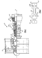
- the engine as shown in Figure 2 may be mounted such that the high pressure turbine 54 is "overhung" bearing mounted.
- the high spool and shaft 32 includes a bearing 142 which supports the high pressure turbine 54 and the high spool 32 on an outer periphery of a shaft that rotates with the high pressure turbine 54.
- the "overhung" mount means that the bearing 142 is at an intermediate location on the spool including the shaft, the high pressure turbine 54, and the high pressure compressor 52. Stated another way, the bearing 142 is supported upstream of a point 501 where the shaft 32 connects to a hub 500 carrying turbine rotors associated with the high pressure turbine (second) turbine section 54.
- the bearing 142 can be positioned inside an annulus 503 formed by the shaft 32 and the hub assembly 500 so as to be between the shaft and the feature numbered 106 and it still would be an "overhung" configuration.
- the forward end of the high spool 32 is supported by a bearing 110 at an outer periphery of the shaft 32.
- the bearings 110 and 142 are supported on static structure 108 associated with the overall engine casings arranged to form the core of the engine as is shown in figure 1 .
- the shaft 30 is supported on a bearing 100 at a forward end.
- the bearing 100 is supported on static structure 102.
- a rear end of the shaft 30 is supported on a bearing 106 which is attached to static structure 104.
Landscapes
- Engineering & Computer Science (AREA)
- Mechanical Engineering (AREA)
- General Engineering & Computer Science (AREA)
- Chemical & Material Sciences (AREA)
- Combustion & Propulsion (AREA)
- Structures Of Non-Positive Displacement Pumps (AREA)
Abstract
A turbine section (28) of a gas turbine engine (20) includes a fan drive turbine section (46) and a second turbine section (54). The fan drive turbine section (46) has a first exit area (401) at a first exit point and is configured to rotate at a first speed. The second turbine section (54) has a second exit area (400) at a second exit point and is configured to rotate at a second speed, which is faster than the first speed.
Description
- This application relates to a gas turbine engine wherein the low pressure turbine section is rotating at a higher speed and centrifugal pull stress relative to the high pressure turbine section speed and centrifugal pull stress than prior art engines.
- Gas turbine engines are known, and typically include a fan delivering air into a low pressure compressor section. The air is compressed in the low pressure compressor section, and passed into a high pressure compressor section. From the high pressure compressor section the air is introduced into a combustion section where it is mixed with fuel and ignited. Products of this combustion pass downstream over a high pressure turbine section, and then a low pressure turbine section.
- Traditionally, on many prior art engines the low pressure turbine section has driven both the low pressure compressor section and a fan directly. As fuel consumption improves with larger fan diameters relative to core diameters it has been the trend in the industry to increase fan diameters. However, as the fan diameter is increased, high fan blade tip speeds may result in a decrease in efficiency due to compressibility effects. Accordingly, the fan speed, and thus the speed of the low pressure compressor section and low pressure turbine section (both of which historically have been coupled to the fan via the low pressure spool), have been a design constraint. More recently, gear reductions have been proposed between the low pressure spool (low pressure compressor section and low pressure turbine section) and the fan.
- A turbine section of a gas turbine engine according to an example of the present disclosure includes a fan drive turbine section and a second turbine section. The fan drive turbine section has a first exit area at a first exit point and is configured to rotate at a first speed. The second turbine section has a second exit area at a second exit point and is configured to rotate at a second speed, which is faster than the first speed. A first performance quantity is defined as the product of the first speed squared and the first area. A second performance quantity is defined as the product of the second speed squared and the second area. A ratio of the first performance quantity to the second performance quantity is less than or equal to about 1.5. The second turbine section is configured to drive a first shaft supported on a bearing, with the bearing forward of the first exit area.
- In a further embodiment of any of the forgoing embodiments, the ratio is above or equal to about 0.5.
- In a further embodiment of any of the forgoing embodiments, the fan drive turbine section has between three and six stages. The second turbine section has two or fewer stages. A pressure ratio across the fan drive turbine section is greater than about 5:1.
- In a further embodiment of any of the forgoing embodiments, the bearing is mounted on an outer periphery of the first shaft at a location that is upstream of a point where the first shaft connects to a hub carrying turbine rotors associated with the second turbine section.
- In a further embodiment of any of the forgoing embodiments, a second shaft associated with the fan drive turbine is supported by a second bearing at an end region of the second shaft, and downstream of the fan drive turbine.
- In a further embodiment of any of the forgoing embodiments, the fan drive and second turbine sections are configured to rotate in opposed directions.
- In a further embodiment of any of the forgoing embodiments, each of the fan drive turbine section and the second turbine section is configured to rotate in a first direction.
- In a further embodiment of any of the forgoing embodiments, there is no bearing support structure positioned intermediate the fan drive and second turbine sections.
- A gas turbine engine according to an example of the present disclosure includes a fan section including a fan, and a compressor section including a first compressor section and a second compressor section. The first compressor section includes fewer stages than the second compressor section. A gear arrangement is configured to drive the fan section. A turbine section includes a fan drive turbine section and a second turbine section. The fan drive turbine is configured to drive the gear arrangement. The fan drive turbine section has a first exit area at a first exit point and is configured to rotate at a first speed. The second turbine section has a second exit area at a second exit point and is configured to rotate at a second speed, which is faster than the first speed. A first performance quantity is defined as the product of the first speed squared and the first area. A second performance quantity is defined as the product of the second speed squared and the second area. A ratio of the first performance quantity to the second performance quantity is less than or equal to about 1.5.
- In a further embodiment of any of the forgoing embodiments, the ratio is above or equal to about 0.8.
- In a further embodiment of any of the forgoing embodiments, the first compressor section includes three stages. The second compressor section includes stages. The fan defines a pressure ratio less than about 1.45.
- A further embodiment of any of the foregoing embodiments includes a combustion section in fluid communication with the compressor section. The second turbine section is configured to drive a first shaft, and the first shaft being mounted on a bearing, with the bearing situated between the combustion section and the first exit area.
- In a further embodiment of any of the forgoing embodiments, the bearing is mounted on an outer periphery of the first shaft at a location upstream of a point where the first shaft connects to a hub carrying turbine rotors associated with the second turbine section.
- In a further embodiment of any of the forgoing embodiments, a second shaft is coupled to the fan drive turbine. The second shaft is supported by a second bearing at an end region of the second shaft and downstream of the fan drive turbine.
- In a further embodiment of any of the forgoing embodiments, a third bearing supports the second compressor section on an outer periphery of the first shaft. A fourth bearing is positioned adjacent the first compressor section, and supports an outer periphery of the second shaft.
- In a further embodiment of any of the forgoing embodiments, the fan drive turbine section and the first compressor section are configured to rotate in a first direction, and the second turbine section and the second compressor section are configured to rotate in a second opposed direction.
- In a further embodiment of any of the forgoing embodiments, each of the fan drive turbine section and the second turbine sections is configured to rotate in a first direction.
- A method of designing a gas turbine engine according to an example of the present disclosure includes providing a fan section including a fan, providing a gear arrangement configured to drive the fan section, providing a compressor section, including both a first compressor and a second compressor, the first compressor section including fewer stages than the second compressor section, providing a turbine section, including both a fan drive turbine section and a second turbine section, the second turbine section is configured to drive a first shaft mounted on a bearing, and driving the compressor section and the gear arrangement via the turbine section. The fan drive turbine section has a first exit area at a first exit point and is configured to rotate at a first speed. The second turbine section has a second exit area at a second exit point and is configured to rotate at a second speed, which is faster than the first speed. A first performance quantity is defined as the product of the first speed squared and the first area at a predetermined design target. A second performance quantity is defined as the product of the second speed squared and the second area at the predetermined design target. A ratio of the first performance quantity to the second performance quantity is between about 0.5 and about 1.5. The bearing is forward of the first exit area.
- In a further embodiment of any of the forgoing embodiments, the predetermined design target corresponds to a takeoff condition.
- In a further embodiment of any of the forgoing embodiments, the first compressor section is upstream of the second compressor section. An overall pressure ratio is provided by the combination of a pressure ratio across the first compressor and a pressure ratio across the second compressor at the predetermined design target. The overall pressure ratio is greater than or equal to about 35. The fan drive turbine section includes between three and six stages. The second turbine section includes two or fewer stages.
- These and other features of this disclosure will be better understood upon reading the following specification and drawings, the following of which is a brief description.
-
-
Figure 1 shows a gas turbine engine. -
Figure 2 schematically shows the arrangement of the low and high spool, along with the fan drive. -
Figure 3 shows a schematic view of a mount arrangement for an engine such as shown inFigures 1 and 2 . -
Figure 1 schematically illustrates agas turbine engine 20. Thegas turbine engine 20 is disclosed herein as a two-turbine turbofan that generally incorporates afan section 22, acompressor section 24, acombustor section 26 and aturbine section 28. Alternative engines might include an augmentor section (not shown) among other systems or features. Thefan section 22 drives air along a bypass flow path B while thecompressor section 24 drives air along a core flow path C for compression and communication into thecombustor section 26 then expansion through theturbine section 28. Although depicted as a turbofan gas turbine engine in the disclosed non-limiting embodiment, it should be understood that the concepts described herein are not limited to use with turbofans as the teachings may be applied to other types of turbine engines including three-turbine architectures. - The
engine 20 generally includes alow speed spool 30 and ahigh speed spool 32 mounted for rotation about an engine central longitudinal axis A relative to an enginestatic structure 36 viaseveral bearing systems 38. It should be understood that various bearingsystems 38 at various locations may alternatively or additionally be provided. - The
low speed spool 30 generally includes aninnermost shaft 40 that interconnects afan 42, a low pressure (or first)compressor section 44 and a low pressure (or first)turbine section 46. Noteturbine section 46 will also be known as a fan drive turbine section. - In the illustrated example, the
low pressure compressor 44 includes fewer stages than thehigh pressure compressor 52, and more narrowly, thelow pressure compressor 44 includes three stages and the high (or second)pressure compressor 52 includes eight stages (Figure 1 ). In another example, thelow pressure compressor 44 includes four stages and the high (or second)pressure compressor 52 includes four stages (Figure 3 ). In the illustrated example, thehigh pressure turbine 54 includes fewer stages than thelow pressure turbine 46, and more narrowly, thelow pressure turbine 46 includes five stages, and thehigh pressure turbine 54 includes two stages. In one example, thelow pressure turbine 46 includes three stages, and thehigh pressure turbine 54 includes two stages (Figure 3 ). - The
inner shaft 40 is connected to thefan 42 through a gearedarchitecture 48 to drive thefan 42 at a lower speed than the low speedfan drive turbine 46. Thehigh speed spool 32 includes a moreouter shaft 50 that interconnects a high pressure (or second)compressor section 52 and high pressure (or second)turbine section 54. Acombustor 56 is arranged between the highpressure compressor section 52 and the highpressure turbine section 54. As used herein, the high pressure turbine section experiences higher pressures than the low pressure turbine section. A low pressure turbine section is a section that powers afan 42. Theinner shaft 40 and theouter shaft 50 are concentric and rotate via bearingsystems 38 about the engine central longitudinal axis A which is collinear with their longitudinal axis. - The core airflow C is compressed by the low
pressure compressor section 44 then the highpressure compressor section 52, mixed and burned with fuel in thecombustor 56, then expanded over the highpressure turbine section 54 and lowpressure turbine section 46. - The
engine 20 in one example is a high-bypass geared aircraft engine. The bypass ratio is the amount of air delivered into bypass path B divided by the amount of air into core path C. In a further example, theengine 20 bypass ratio is greater than about six, with an example embodiment being greater than ten, the gearedarchitecture 48 is an epicyclic gear train, such as a planetary gear system or other gear system, with a gear reduction ratio of greater than about 2.3 and the lowpressure turbine section 46 has a pressure ratio that is greater than about five. In one disclosed embodiment, theengine 20 bypass ratio is greater than about ten, the fan diameter is significantly larger than that of the lowpressure compressor section 44, and the lowpressure turbine section 46 has a pressure ratio that is greater than about 5:1. In some embodiments, the high pressure turbine section may have two or fewer stages. In contrast, the lowpressure turbine section 46, in some embodiments, has between 3 and 6 stages. Further the lowpressure turbine section 46 pressure ratio is total pressure measured prior to inlet of lowpressure turbine section 46 as related to the total pressure at the outlet of the lowpressure turbine section 46 prior to an exhaust nozzle. The gearedarchitecture 48 may be an epicycle gear train, such as a star gear system or other gear system, with a gear reduction ratio of greater than about 2.5:1. It should be understood, however, that the above parameters are only exemplary of one embodiment of a geared architecture engine. - A significant amount of thrust is provided by the bypass flow B due to the high bypass ratio. The
fan section 22 of theengine 20 is designed for a particular flight condition -- typically cruise at about 0.8 Mach and about 35,000 feet (10,668 m). The flight condition of 0.8 Mach and 35,000 ft (10,668 m), with the engine at its best fuel consumption - also known as "bucket cruise Thrust Specific Fuel Consumption ("TSFC"). TSFC is the industry standard parameter of the rate of lbm of fuel being burned per hour divided by lbf of thrust the engine produces at that flight condition. "Low fan pressure ratio" is the ratio of total pressure across the fan blade alone, before the fan exit guide vanes. The low fan pressure ratio as disclosed herein according to one non-limiting embodiment is less than about 1.45. "Low corrected fan tip speed" is the actual fan tip speed in ft/sec divided by an industry standard temperature correction of [(Ram Air Temperature deg R) / 518.7)0.5 (where °R = K x 9/5)]. The "Low corrected fan tip speed" as disclosed herein according to one non-limiting embodiment is less than about 1150 ft / second (350.5 m/s). Further, thefan 42 may have 26 or fewer blades. - An
exit area 400 is shown, inFigure 1 and Figure 2 , at the exit location for the highpressure turbine section 54 is the annular area of the last blade ofturbine section 54. An exit area for the low pressure turbine section is defined atexit 401 for the low pressure turbine section is the annular area defined by the last blade of thatturbine section 46. As shown inFigure 2 , theturbine engine 20 may be counterrotating. This means that the lowpressure turbine section 46 and lowpressure compressor section 44 rotate in one direction ("-'), while thehigh pressure spool 32, including highpressure turbine section 54 and highpressure compressor section 52 rotate in an opposed direction ("+"). Thegear reduction 48, which may be, for example, an epicyclic transmission (e.g., with a sun, ring, and star gears), is selected such that thefan 42 rotates in the same direction ("+") as thehigh spool 32. With this arrangement, and with the other structure as set forth above, including the various quantities and operational ranges, a very high speed can be provided to the low pressure spool. Low pressure turbine section and high pressure turbine section operation are often evaluated looking at a performance quantity which is the exit area for the turbine section multiplied by its respective speed squared. This performance quantity ("PQ") is defined as:

- Thus, a ratio of the performance quantity for the low pressure turbine section compared to the performance quantify for the high pressure turbine section is:

- In one turbine embodiment made according to the above design, the areas of the low and high pressure turbine sections are 557.9 in2 (3599 cm2) and 90.67 in2 (585 cm2), respectively. Further, the speeds of the low and high pressure turbine sections are 10179 rpm and 24346 rpm, respectively. Thus, using Equations 1 and 2 above, the performance quantities for the low and high pressure turbine sections are:


- In another embodiment, the ratio was about 0.5 and in another embodiment the ratio was about 1.5. With PQltp/ PQhpt ratios in the 0.5 to 1.5 range, a very efficient overall gas turbine engine is achieved. More narrowly, PQltp/ PQhpt ratios of above or equal to about 0.8 are more efficient. Even more narrowly, PQltp/ PQhpt ratios above or equal to 1.0 are even more efficient. As a result of these PQltp/ PQhpt ratios, in particular, the turbine section can be made much smaller than in the prior art, both in diameter and axial length. In addition, the efficiency of the overall engine is greatly increased.
- The low pressure compressor section is also improved with this arrangement, and behaves more like a high pressure compressor section than a traditional low pressure compressor section. It is more efficient than the prior art, and can provide more compression in fewer stages. The low pressure compressor section may be made smaller in radius and shorter in length while contributing more toward achieving an overall pressure ratio design target of the engine. In some examples,
engine 20 is designed at a predetermined design target defined by performance quantities for the low and highpressure turbine sections high pressure compressors - In some examples, the overall pressure ratio corresponding to the predetermined design target is greater than or equal to about 35:1. That is, after accounting for a pressure rise of the
fan 42 in front of thelow pressure compressor 44, the pressure of the air entering the low (or first)compressor section 44 should be compressed as much or over 35 times by the time it reaches an outlet of the high (or second)compressor section 52. In other examples, an overall pressure ratio corresponding to the predetermined design target is greater than or equal to about 40:1, or greater than or equal to about 50:1. In some examples, the predetermined design target is defined at sea level and at a static, full-rated takeoff power condition. In other examples, the predetermined design target is defined at a cruise condition. - As shown in
Figure 3 , the engine as shown inFigure 2 may be mounted such that thehigh pressure turbine 54 is "overhung" bearing mounted. As shown, the high spool andshaft 32 includes abearing 142 which supports thehigh pressure turbine 54 and thehigh spool 32 on an outer periphery of a shaft that rotates with thehigh pressure turbine 54. As can be appreciated, the "overhung" mount means that thebearing 142 is at an intermediate location on the spool including the shaft, thehigh pressure turbine 54, and thehigh pressure compressor 52. Stated another way, thebearing 142 is supported upstream of apoint 501 where theshaft 32 connects to ahub 500 carrying turbine rotors associated with the high pressure turbine (second)turbine section 54. Note that the bearing 142 can be positioned inside anannulus 503 formed by theshaft 32 and thehub assembly 500 so as to be between the shaft and the feature numbered 106 and it still would be an "overhung" configuration. - The forward end of the
high spool 32 is supported by abearing 110 at an outer periphery of theshaft 32. Thebearings static structure 108 associated with the overall engine casings arranged to form the core of the engine as is shown infigure 1 . In addition, theshaft 30 is supported on abearing 100 at a forward end. Thebearing 100 is supported onstatic structure 102. A rear end of theshaft 30 is supported on abearing 106 which is attached tostatic structure 104. - With this arrangement, there is no bearing support struts or other structure in the path of hot products of combustion passing downstream of the
high pressure turbine 54, and no bearing compartment support struts in the path of the products of combustion as they flow across to thelow pressure turbine 46. - As shown, there is no mid-turbine frame or bearings mounted in the
area 402 between theturbine sections - While this invention has been disclosed with reference to one embodiment, it should be understood that certain modifications would come within the scope of this invention. For that reason, the following claims should be studied to determine the true scope and content of this invention.
Claims (15)
- A turbine section (28) of a gas turbine engine (20), comprising:a fan drive turbine section (46); anda second turbine section (54), wherein said fan drive turbine section (46) has a first exit area (401) at a first exit point and is configured to rotate at a first speed, said second turbine section (54) has a second exit area (400) at a second exit point and is configured to rotate at a second speed which is faster than the first speed, a first performance quantity is defined as the product of the first speed squared and the first area (401), a second performance quantity is defined as the product of the second speed squared and the second area (400), a ratio of the first performance quantity to the second performance quantity is less than or equal to about 1.5, and said second turbine section (54) is configured to drive a first shaft (32) supported on a bearing (142), with said bearing (142) being forward of said first exit area (401).
- The turbine section (28) as set forth in claim 1, wherein said ratio is above or equal to about 0.5.
- The turbine section (28) as set forth in claim 1 or 2, wherein said fan drive turbine section (46) has between three and six stages, said second turbine section (54) has two or fewer stages, and a pressure ratio across said fan drive turbine section is greater than about 5:1.
- The turbine section (28) as set forth in claim 1, 2 or 3, wherein said bearing (142) is mounted on an outer periphery of said first shaft (32) at a location that is upstream of a point (501) where said first shaft (32) connects to a hub (500) carrying turbine rotors associated with said second turbine section (54).
- The turbine section (28) as set forth in any preceding claim, wherein a second shaft (30) associated with said fan drive turbine (46) is supported by a second bearing (106) at an end region of said second shaft (30), and downstream of said fan drive turbine (46).
- The turbine section (28) as set forth in any preceding claim, wherein said fan drive and second turbine sections (46, 54) are configured to rotate in opposed directions.
- The turbine section (28) as set forth in any of claims 1 to 5, wherein each of said fan drive turbine section (46) and said second turbine section (54) is configured to rotate in a first direction.
- The turbine section (28) as set forth in any preceding claim, wherein there is no bearing support structure positioned intermediate said fan drive and second turbine sections (46, 54).
- A gas turbine engine (20), comprising:a fan section (22) including a fan (42);a compressor section (24) including a first compressor section (44) and a second compressor section (52), said first compressor section (44) including fewer stages than said second compressor section (52);a gear arrangement (48) configured to drive said fan section (22); anda turbine section (28) including a fan drive turbine section (46) and a second turbine section (54), said fan drive turbine section (46) configured to drive said gear arrangement (48), wherein said fan drive turbine section (46) has a first exit area (401) at a first exit point and is configured to rotate at a first speed, said second turbine section (54) has a second exit area (400) at a second exit point and is configured to rotate at a second speed which is faster than the first speed, a first performance quantity is defined as the product of the first speed squared and the first area (401), a second performance quantity is defined as the product of the second speed squared and the second area (400), and a ratio of the first performance quantity to the second performance quantity is less than or equal to about 1.5.
- The engine (20) as set forth in claim 9, wherein said ratio is above or equal to about 0.8, optionally wherein said first compressor section (44) includes three stages, said second compressor section (52) includes eight stages, and said fan (42) defines a pressure ratio less than 1.45.
- The engine (20) as set forth in claim 9 or 10, comprising a combustion section (26) in fluid communication with said compressor section (24), wherein said second turbine section (54) is configured to drive a first shaft (32), and said first shaft (32) is mounted on a bearing (142).
- The engine (20) as set forth in claim 11, wherein said bearing (142) is mounted on an outer periphery of said first shaft (32) at a location upstream of a point (501) where said first shaft (32) connects to a hub (500) carrying turbine rotors associated with said second turbine section (54).
- The engine (20) as set forth in claim 11 or 12, wherein a second shaft (30) is coupled to said fan drive turbine (46), said second shaft (30) supported by a second bearing (106) at an end region of said second shaft (30) and downstream of said fan drive turbine (46), optionally wherein a third bearing (110) supports said second compressor section (52) on an outer periphery of said first shaft (32), and a fourth bearing (100) is positioned adjacent said first compressor section (44), and supports an outer periphery of said second shaft (30).
- The engine (20) as set forth in any of claims 9 to 13, wherein said fan drive turbine section (46) and said first compressor section (44) are configured to rotate in a first direction, and said second turbine section (54) and said second compressor section (52) are configured to rotate in a second opposed direction.
- The engine (20) as set forth in any of claims 9 to 13, wherein each of said fan drive turbine section (46) and said second turbine section (54) is configured to rotate in a first direction.
Applications Claiming Priority (1)
| Application Number | Priority Date | Filing Date | Title |
|---|---|---|---|
| US14/922,386 US20160047306A1 (en) | 2012-01-31 | 2015-10-26 | Gas turbine engine with high speed low pressure turbine section and bearing support features |
Publications (1)
| Publication Number | Publication Date |
|---|---|
| EP3163033A1 true EP3163033A1 (en) | 2017-05-03 |
Family
ID=57233305
Family Applications (1)
| Application Number | Title | Priority Date | Filing Date |
|---|---|---|---|
| EP16195861.6A Withdrawn EP3163033A1 (en) | 2015-10-26 | 2016-10-26 | Gas turbine engine with high speed low pressure turbine section and bearing support features |
Country Status (1)
| Country | Link |
|---|---|
| EP (1) | EP3163033A1 (en) |
Citations (4)
| Publication number | Priority date | Publication date | Assignee | Title |
|---|---|---|---|---|
| US20030163983A1 (en) * | 2002-03-01 | 2003-09-04 | Seda Jorge F. | Counter rotating aircraft gas turbine engine with high overall pressure ratio compressor |
| US20130192258A1 (en) * | 2012-01-31 | 2013-08-01 | United Technologies Corporation | Geared turbofan gas turbine engine architecture |
| US20130195621A1 (en) * | 2012-01-31 | 2013-08-01 | Frederick M. Schwarz | Gas turbine engine with high speed low pressure turbine section and bearing support features |
| US20140020404A1 (en) * | 2012-05-31 | 2014-01-23 | United Technologies Corporation | Fundamental gear system architecture |
-
2016
- 2016-10-26 EP EP16195861.6A patent/EP3163033A1/en not_active Withdrawn
Patent Citations (4)
| Publication number | Priority date | Publication date | Assignee | Title |
|---|---|---|---|---|
| US20030163983A1 (en) * | 2002-03-01 | 2003-09-04 | Seda Jorge F. | Counter rotating aircraft gas turbine engine with high overall pressure ratio compressor |
| US20130192258A1 (en) * | 2012-01-31 | 2013-08-01 | United Technologies Corporation | Geared turbofan gas turbine engine architecture |
| US20130195621A1 (en) * | 2012-01-31 | 2013-08-01 | Frederick M. Schwarz | Gas turbine engine with high speed low pressure turbine section and bearing support features |
| US20140020404A1 (en) * | 2012-05-31 | 2014-01-23 | United Technologies Corporation | Fundamental gear system architecture |
Non-Patent Citations (2)
| Title |
|---|
| BRUCE E WENDUS ET AL: "Follow-On Technology Requirement Study for Advanced Subsonic Transport", NASA, 1 August 2003 (2003-08-01), XP055279476, Retrieved from the Internet <URL:https://ntrs.nasa.gov/search.jsp?R=20030067946> [retrieved on 20160610] * |
| JAYANT SABNIS ET AL: "THE PW1000G PURE POWER NEW ENGINE THE PW1000G PURE POWER NEW ENGINE CONCEPT AND ITS IMPACT ON MRO Jayant Sabnis Vice President, System Functional Design Av Week Engine MRO Forum", 1 December 2010 (2010-12-01), Av Week engine MRO Forum, Munich, Germany, pages 1 - 45, XP055155486, Retrieved from the Internet <URL:http://events.aviationweek.com/html/mroeng10/Day2 - The PW1000G Pure Power New Engine Concept.SABNIS (P&W).pdf> [retrieved on 20141127] * |
Similar Documents
| Publication | Publication Date | Title |
|---|---|---|
| US20250188871A1 (en) | Gas turbine engine with high speed low pressure turbine section and bearing support features | |
| US9816442B2 (en) | Gas turbine engine with high speed low pressure turbine section | |
| EP3557074A1 (en) | Gas turbine engine with high speed low pressure turbine section | |
| US9611859B2 (en) | Gas turbine engine with high speed low pressure turbine section and bearing support features | |
| EP3594483A1 (en) | Gas turbine engine with mount for low pressure turbine section | |
| EP3708792A1 (en) | Gas turbine engine with high speed low pressure turbine section and bearing support features | |
| CA2853839C (en) | Gas turbine engine with high speed low pressure turbine section and bearing support features | |
| US20250341175A1 (en) | Gas turbine engine with high speed low pressure turbine section and bearing support features | |
| EP3032084A1 (en) | Gas turbine engine with high speed low pressure turbine section | |
| US9835052B2 (en) | Gas turbine engine with high speed low pressure turbine section and bearing support features | |
| EP3165757A1 (en) | Gas turbine engine with high speed low pressure turbine section | |
| US20160115865A1 (en) | Gas turbine engine with high speed low pressure turbine section and bearing support features | |
| EP3165755A1 (en) | Gas turbine engine with high speed low pressure turbine section and bearing support features | |
| EP3165753A1 (en) | Gas turbine engine with mount for low pressure turbine section | |
| US20160053634A1 (en) | Gas turbine engine with high speed low pressure turbine section and bearing support features | |
| US20160053679A1 (en) | Gas turbine engine with high speed low pressure turbine section and bearing support features | |
| EP3163033A1 (en) | Gas turbine engine with high speed low pressure turbine section and bearing support features | |
| EP3163062A1 (en) | Gas turbine engine with high speed low pressure turbine section and bearing support features | |
| EP3165754A1 (en) | Gas turbine engine with high speed low pressure turbine section and bearing support features | |
| US20160053631A1 (en) | Gas turbine engine with mount for low pressure turbine section | |
| US20160047306A1 (en) | Gas turbine engine with high speed low pressure turbine section and bearing support features | |
| EP3034849A1 (en) | Gas turbine engine with high speed low pressure turbine section |
Legal Events
| Date | Code | Title | Description |
|---|---|---|---|
| PUAI | Public reference made under article 153(3) epc to a published international application that has entered the european phase |
Free format text: ORIGINAL CODE: 0009012 |
|
| AK | Designated contracting states |
Kind code of ref document: A1 Designated state(s): AL AT BE BG CH CY CZ DE DK EE ES FI FR GB GR HR HU IE IS IT LI LT LU LV MC MK MT NL NO PL PT RO RS SE SI SK SM TR |
|
| AX | Request for extension of the european patent |
Extension state: BA ME |
|
| STAA | Information on the status of an ep patent application or granted ep patent |
Free format text: STATUS: THE APPLICATION IS DEEMED TO BE WITHDRAWN |
|
| 18D | Application deemed to be withdrawn |
Effective date: 20171104 |