EP3162956A1 - Feed system of a fiber web machine - Google Patents
Feed system of a fiber web machine Download PDFInfo
- Publication number
- EP3162956A1 EP3162956A1 EP16192228.1A EP16192228A EP3162956A1 EP 3162956 A1 EP3162956 A1 EP 3162956A1 EP 16192228 A EP16192228 A EP 16192228A EP 3162956 A1 EP3162956 A1 EP 3162956A1
- Authority
- EP
- European Patent Office
- Prior art keywords
- stock
- equipment
- feed
- feed line
- density
- Prior art date
- Legal status (The legal status is an assumption and is not a legal conclusion. Google has not performed a legal analysis and makes no representation as to the accuracy of the status listed.)
- Granted
Links
Images

Classifications
-
- D—TEXTILES; PAPER
- D21—PAPER-MAKING; PRODUCTION OF CELLULOSE
- D21F—PAPER-MAKING MACHINES; METHODS OF PRODUCING PAPER THEREON
- D21F11/00—Processes for making continuous lengths of paper, or of cardboard, or of wet web for fibre board production, on paper-making machines
- D21F11/002—Processes for making continuous lengths of paper, or of cardboard, or of wet web for fibre board production, on paper-making machines by using a foamed suspension
-
- D—TEXTILES; PAPER
- D21—PAPER-MAKING; PRODUCTION OF CELLULOSE
- D21F—PAPER-MAKING MACHINES; METHODS OF PRODUCING PAPER THEREON
- D21F1/00—Wet end of machines for making continuous webs of paper
- D21F1/02—Head boxes of Fourdrinier machines
-
- D—TEXTILES; PAPER
- D21—PAPER-MAKING; PRODUCTION OF CELLULOSE
- D21F—PAPER-MAKING MACHINES; METHODS OF PRODUCING PAPER THEREON
- D21F1/00—Wet end of machines for making continuous webs of paper
- D21F1/04—Head boxes of cylinder machines
-
- D—TEXTILES; PAPER
- D21—PAPER-MAKING; PRODUCTION OF CELLULOSE
- D21G—CALENDERS; ACCESSORIES FOR PAPER-MAKING MACHINES
- D21G9/00—Other accessories for paper-making machines
- D21G9/0009—Paper-making control systems
- D21G9/0018—Paper-making control systems controlling the stock preparation
-
- D—TEXTILES; PAPER
- D21—PAPER-MAKING; PRODUCTION OF CELLULOSE
- D21H—PULP COMPOSITIONS; PREPARATION THEREOF NOT COVERED BY SUBCLASSES D21C OR D21D; IMPREGNATING OR COATING OF PAPER; TREATMENT OF FINISHED PAPER NOT COVERED BY CLASS B31 OR SUBCLASS D21G; PAPER NOT OTHERWISE PROVIDED FOR
- D21H21/00—Non-fibrous material added to the pulp, characterised by its function, form or properties; Paper-impregnating or coating material, characterised by its function, form or properties
- D21H21/06—Paper forming aids
-
- D—TEXTILES; PAPER
- D21—PAPER-MAKING; PRODUCTION OF CELLULOSE
- D21H—PULP COMPOSITIONS; PREPARATION THEREOF NOT COVERED BY SUBCLASSES D21C OR D21D; IMPREGNATING OR COATING OF PAPER; TREATMENT OF FINISHED PAPER NOT COVERED BY CLASS B31 OR SUBCLASS D21G; PAPER NOT OTHERWISE PROVIDED FOR
- D21H21/00—Non-fibrous material added to the pulp, characterised by its function, form or properties; Paper-impregnating or coating material, characterised by its function, form or properties
- D21H21/06—Paper forming aids
- D21H21/12—Defoamers
-
- G—PHYSICS
- G01—MEASURING; TESTING
- G01N—INVESTIGATING OR ANALYSING MATERIALS BY DETERMINING THEIR CHEMICAL OR PHYSICAL PROPERTIES
- G01N9/00—Investigating density or specific gravity of materials; Analysing materials by determining density or specific gravity
Definitions
- the invention relates to a feed system of a fiber web machine, which system includes:
- Foam forming performed on the fiber web machine is known from prior art. Foam forming can also be called foam web formation.
- foam forming one or more agents are added to the stock, which is intended to be formed into a web and which is fed into the headbox, for example in the short circulation of the fiber web machine for the implementation of foam forming.
- the agents added can include foaming agents such as air and antifoaming agents.
- Surface active agents can be mentioned as an example of antifoaming agents. These can be used for controlling foam generation for example by adjusting the bubble size. By changing the mutual ratio of these agents, the goal is to obtain the desired type of foam generation, web formation and/or the properties of the end product produced.
- the purpose of the present invention is to accomplish a feed system of a fiber web machine, where it is possible to adjust the amount of one or more agents affecting foam generation in the stock to be formed into a web.
- the characteristics of the system according to the invention are presented in claim 1.
- the feed system includes measuring equipment for determining the density of the stock, adapted in the feed line before and after the foam generation equipment, and in addition to the measuring equipment also control equipment, which has been adapted, on the basis of the determination of density, to control the foam generation equipment for the feeding of one or more agents into the stock for foam forming.
- the density of the stock has been adapted to be determined before and after foam generation. On the basis of these determinations, it is possible to adjust the feeding of one or more agents that affect foam generation, and hence to affect foam generation, web formation in the headbox and/or the properties of the end product to be formed into a web in a more effective and controlled manner.
- the measuring equipment for the measurement of density has been adapted in the feed line before the feeding of one or more agents into the stock for foam forming.
- the measuring equipment adapted after the foam generation equipment it is possible to find out the effect of the agents, which are dosed into the stock in the feed line and which affect foam generation, on the density of the stock.
- foam generation can be controlled precisely, which has an effect on the above-mentioned factors.
- the feed system can also include a bypass line in order to arrange bypass to the headbox.
- the measuring equipment adapted after the foam generation equipment for the determination of the density of the stock can be adapted in the bypass line.
- the arrangement of the measuring equipment in the bypass line provides a simple way to arrange the measurement after foam generation, because there is typically more space available in the bypass line than in the feed line before the headbox.
- measurement carried out in the bypass line correlates with the headbox density of the stock at a reasonable accuracy. Measurement carried out in the bypass line indicates issues such as the permanence of foam in the stock to be formed into a web.
- density measurement carried out in the bypass line enables the determination of the amount of stock air content that has travelled through the headbox, which amount affects issues such as the formation and bulk of the web.
- Measurement carried out in the bypass line indicates the air content of the foamed stock to be formed into a web in the headbox, which air content in practice corresponds to or is at least proportionate to the air content of the stock fed from the headbox to the forming section and hence also corresponds to or is proportionate to the formation and bulk of the web formed.
- the measuring equipment adapted after the foam generation equipment can also be located as early as before the headbox for example in the feed line and/or in the headbox itself. These are possible especially if there is no bypass in the headbox.
- the measuring equipment adapted in the feed line can be between the pump belonging to the feed line and the foam generation equipment.
- the pump is used for mixing stock, which has been brought into a wire pit, into tail water.
- the measuring equipment adapted after the pump but before the foam generation equipment can be used for finding out the density of the stock to be formed into a web, composed of several components, which density is affected for example by the foam coming with the tail water.
- the foam generation equipment adapted in the feed line can be used for adjusting the density of the stock to the desired direction.
- the measuring equipment adapted in the feed line has been adapted between the pump and a machine screen also included in the feed line. This location simplifies the arrangement of the measurement and is often advantageous from the point of view of the space required by the measurement.
- density can be measured also in the dilution water system. This can take place for example in the bypass line of the dilution water system. In this way, the density of the dilution water flow fed into the headbox using the dilution water system can be adjusted in the desired manner in relation to the density of the main flow fed into the headbox.
- a small side flow can be taken from the feed and/or bypass lines for the determination of density, from which side flow density can be measured.
- the pipe size of the side flow is smaller than the pipe size of the actual main flow, in which case the arrangement of density measurement using existing measuring devices is challenging. This simplifies the arrangement of density measurement in the feed system.
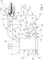
- Figure 1 shows an example in principle of a feed system of a fiber web machine as a schematic diagram, where the feed system is connected to a headbox 10 of a fiber web machine.
- the main parts of the feed system of the fiber web machine are a feed line 12, potential bypass line 14 and foam generation equipment 13 for the foam forming of stock 31 in the headbox 10, more generally on the fiber web machine.
- the feed system can be connected to production equipment 11 for the production of stock 31 intended to be formed into a web in the headbox 10 from one or more thick stock components 29 and from filtrate 43.
- the production equipment 11 can be known as such from prior art. In Figure 1 , only a wire pit 23 is illustrated of the production equipment 11. For a person having ordinary skill in the art, it is obvious that the production equipment 11 can include a large number of other equipment known as such and familiar to a person having ordinary skill in the art, which other equipment is not illustrated in Figure 1 .
- At least one thick stock component 29 is brought into the wire pit 23 from the production equipment (not illustrated) preceding the wire pit 23.
- the thick stock component 29 is fed into the wire pit 23 through a connection arranged near its bottom, and led into the wire pit 23.
- the thick stock component 29 can be discharged into the wire pit 23 near its outlet connection 30.
- Filtrates 43 can be brought into the wire pit 23 from several sources known as such.
- One example are waters removed from the web on the forming section following the headbox 10 of a fiber web machine.
- the filtrates 43 can also include other waters coming from the fiber web machine.
- a potential bypass of the headbox 10 and a potential bypass of the dilution water of the headbox 10 are also led into the wire pit 23.
- filtrates can be brought from the production equipment preceding the wire pit 23.
- the feed system according to the invention can be part of the short circulation of the fiber web machine.
- feed line 12 stock 31 is taken towards the headbox 10 of the fiber web machine.
- the feed line 12 is connected to the stock 31 production equipment 11, now especially to the wire pit 23, to an outlet connection 30 adapted in its lower part.
- the feed line 12 is composed of at least one pipeline 42 adapted to lead the flow, to which pipeline 42 various equipment has been connected.
- the equipment can be known as such from prior art.
- the equipment and hence also the feed line 12 includes a headbox 10 feed pump 17 and machine screen 18 adapted after the production equipment 11, more specifically after the wire pit 23.
- Foam generation equipment 13 has been adapted in the feed line 12.
- the foam generation equipment 13 adapted in the feed line 12 has been adapted for example for the feeding of one or more agents 41 into the stock 31 for foam forming.
- the foam generation equipment 13 can include for example an agent source and an actuator such as a valve for the dosing of the agent 41 from the agent source into the feed line 12.
- the feed line 12 has a connection, through which the agent 41 is dosed into the pipeline 42. The technology related to this can also be known as such from prior art.
- the foam generation equipment 13 can also include mixing equipment for the mixing of the agents 41 into the stock 31 and/or for foam generation. These can also be adapted in the feed line 12.
- the agents 41 to be dosed into the feed line 12 can also be known as such from prior art.
- Foam can be generated using one or more agents 41.
- the agent can be for example a gas such as air.
- foam generation can be restrained for example by means of one or more surface active agents. These can be used for controlling the bubble size.
- These one or more agents that control foam generation are also dosed into the feed line 12 using foam generation equipment 13.
- foam generation equipment 13 There can be several units of foam generation equipment 13 in the feed line 12, and they can be separate from one another. There can be separate equipment for each agent. On the other hand, the adding of several agents can also take place using the same equipment.
- the headbox 10 can be known as such from prior art. It can be for example a headbox 10 based on a turbulence generator.
- the stock 32 to the formed into a web discharges from the slice opening of the headbox 10 to the forming section of the fiber web machine.
- the stock 32 to the formed into a web is distributed over the entire width of the headbox 10 in the cross direction of the machine by means of a header 24 in a manner known as such.
- the feed line 12 is connected to the wider end of the header 24 for the feeding of the stock 32 to the formed into a web into the headbox 10.
- an optional bypass line 14 for the stock 33 can be connected to the opposite end of the header 24, which end can also be narrower than the wider end, for the arrangement of bypass to the headbox 10.
- the bypass line 14 can also be part of the feed system.
- the stock 33 which has flown through the header 24 of the headbox 10 and which has not yet ended up in web formation, is led from the headbox 10 of the fiber web machine back to the stock 31 production equipment 11, here more specifically into the wire pit 23, or more generally back to the feed system.
- the bypass line 14 can also be referred to as the bypass of the headbox 10.
- the headbox 10 can also be without bypass, in other words without the bypass line 14 illustrated in Figure 1 .
- the system includes measuring equipment 15.1, 15.2 for the determination of the density of the stock 31, 33. Moreover, the system also includes control equipment 16 for the controlling of foam generation. Measuring equipment 15.1 has been adapted in the feed line 12 before the foam generation equipment 13 adapted in the feed line 12. Moreover, measuring equipment 15.2 has also been adapted after the foam generation equipment 13. The control equipment 16 has been adapted to control the foam generation equipment 13 for the foam forming of the stock 31 on the basis of the density determination performed using the measuring equipment 15.1, 15.2. More specifically, the control equipment 16 has been adapted to control the foam generation equipment 13 for the feeding of one or more agents 41 into the stock 31 for foam forming on the basis of the density determination performed using the measuring equipment 15.1, 15.2.
- the control equipment 16 can be part of the machine control automation, which has been adapted to operate for example in a pre-controlled manner.
- the control equipment 16 is used for controlling for example the operation of valves included in the foam generation equipment 13, with which valves the feeding of the agents is controlled.
- the control equipment 16 can also be used for controlling the operation of potential mixing equipment affecting foam generation.
- the measuring equipment 15.1 has been adapted in the feed line 12 before the foam generation equipment 13 for the feeding of one or more agents 41 into the stock 31 for foam forming. In this way, it is possible to find out the state of the foam generation of the stock 31 coming from the production equipment 11 and intended to be formed into a web without the agents 41 affecting foam generation yet fed into the stock 31 in the feed line cycle in question.
- measuring equipment 15.2 has also been adapted in the bypass line 14 for the determination of the density of the stock 33 after the foam generation equipment 13.
- Density measurement carried out in the bypass line 14, in other words in the bypass of the headbox 10, or more generally measuring equipment 15.2 adapted after the foam generation equipment 13 can be used, in turn, for determining the air content, in other words the amount of foam. This has an effect on issues such as the formation and bulk of the web.
- Measurement carried out in the bypass indicates the air content of the foamed stock 32 fed into the headbox 10 and formed into a web.
- the result of the measurement carried out in the bypass line corresponds to or is at least proportionate to the air content of the stock fed from the headbox 10 to the forming section and hence also corresponds to or is proportionate to the formation and bulk of the web formed.
- the cycle time of short circulation is typically approximately 10 seconds, so the foam has to endure that time. Measurement carried out in the bypass line 14 indicates this.
- this measurement carried out after the foam generation equipment 13 can be performed before the headbox 10 or even in the headbox 10 itself.
- density measurement carried out after the foam generation equipment 13 is not restricted to this presented measurement carried out in the bypass after the headbox 10, but the carrying out of the measurement before the headbox 10 (in the foamed stock 32 to be formed into a web) or even in the headbox itself (for example in the header 24) is also possible.
- the density of the stock fed into the headbox 10 can be found out and it can be adjusted by means of a system, where the density of the stock circulating in the feed system belonging to the short circulation is measured before and after the headbox 10, and more generally, before and after foam generation, at sufficient accuracy. This information and its accuracy are relevant so that the jet speed of the headbox 10 can be adjusted reliably.
- the accuracy requirement for the measurement can be for example 1% or even below it.
- the system is also used for obtaining information on how the foam circulates in the short circulation, whether there is enough foam, whether the quality of the foam is good (does not cause splashing) and information on other matters related to foam generation.
- One way of arranging the measuring equipment 15.1 in the feed line 12 before the foam generation equipment 13 is to adapt it between the pump 17 arranged for the feeding of the headbox 10 of the fiber web machine, belonging to the feed line 12, and the foam generation equipment 13.
- the pump 17 follows the production equipment 11, in other words in this case the wire pit 23.
- the pump 17 is used for mixing the thick stock component 29 and the tail water, in which case density measurement carried out after this but before the foam generation equipment 13 gives a correct view of the air content before foam generation.
- the feed line 12 can also include a machine screen 18 arranged after the pump 17.
- the machine screen 18 is in the feed line 12 before the foam generation equipment 13.
- the measuring equipment 15.1 adapted in the feed line 12 before foam generation equipment 13 can be adapted between the pump 17 and the machine screen 18.
- a correct view is obtained of the air content before foam generation, and this is also an advantageous embodiment in respect of the use of space, if the foam generation equipment 13 follows the machine screen 18 after a short distance.
- the system can also include a dilution water system 19. Its operation and purpose as such are familiar to a person having ordinary skill in the art.
- the dilution water system 19 includes feed and bypass lines 20, 21 in the corresponding manner.
- the feed line 20 of dilution water has a feed pump 37 of dilution water 34 and a screen 38 of dilution water 34 following the feed pump 37.
- the feeding of dilution water 35 from the header 27 into the main flow of the headbox 10 can be implemented in a selected manner.
- the feed line 20 of the dilution water system 19 can also include foam generation equipment 13 for the feeding of one or more agents 41 into the dilution water 34 for foam forming.
- the foam generation equipment 13 can be after the pump 37 and screen 38 adapted in the feed line 20 of dilution water.
- the dilution water system 19 can also include measuring equipment 15.3 for the measurement of the density of dilution water 36.
- the measuring equipment 15.3 can be adapted in the dilution water system 19 in its bypass line 21. In this case, the measuring equipment 15.3 is in the dilution water system 19 after the foam generation equipment 13 included in the dilution water system 19.
- the feed line 20 of the dilution water system 19 is now connected to the corresponding part of the production equipment 11 as to which the feed line 12 of the stock 31 is connected. This part of the production equipment 11, to which part at least one of the feed lines 12, 20 is connected, is now a wire pit 23.
- the headbox density is the difference in density between the stock 32, which is led to the headbox 10 and formed into a web, and dilution water 35.
- orientation problems are reduced by means of density measurement carried out in the dilution water system 19.
- Orientation problems may be caused if the density of the dilution water and the density of the stock to be formed into a web do not differ from each other sufficiently.
- the density of the dilution water can be adjusted to be optimal, in which case the targeted advantages can be achieved with it.
- the measuring equipment 15.1 - 15.3 includes at least one radioactive measuring device 26, which can be known as such.
- One example is a densitometer of Berthold Technologies based on radioactive radiation.
- the densitometer can be installed easily to measure the stock traveling in the pipeline. In these, radiation is typically used for measuring the mass of the stock traveling through the measuring device 26, and the density of the stock can be calculated from the mass.
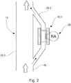
- Figure 2 shows one solution in principle of the arrangement of measurement in connection with a pipeline 42, such as specifically a feed line 12 and/or bypass line 14.
- the solution presented is suited especially to the measurement of the density of stock in pipelines 42 with a large diameter. Since the diameter of these pipelines 42 can be several hundred millimeters, such as more than 300 mm, this sets its own challenge to the measurement of the density of stock and hence to the determination of foam generation in respect of the arrangement of the measuring equipment 15.1, 15.2. In paper and board production environments, these types of pipeline sizes are very typical for example in taking the stock to the headbox 10 and also in implementing its bypass. The adding of agents 41, which affect foam generation, into the stock 31 typically takes place in connection with these large pipelines 42.
- One simple solution to this is to divide the flow of the feed and/or bypass line 12, 14 into two partial flows, as shown in Figure 2 , which partial flows travel in their own channels 25.1, 25.2.
- One of the two partial flows has been arranged to travel in the channel 25.2 with an essentially smaller diameter.
- An example of the diameter of this smaller channel 25.2 can be 75 - 100 mm.
- the diameter of the main line channel 25.1 can be more than 300 mm.
- the velocity of the flow has no effect on the measurement. The measurement works well, because the stock in the pipeline is pressurized to a pressure over the atmospheric pressure.
- measuring equipment 15.1 can again be a radioactive measuring device 26. Due to the smaller channel 25.2, it is possible to carry out the density measurement using commercial instruments which are easily available. In this case, they do not need to be specifically tailored for the considerably larger main line 25.1.
- the relatively larger main line 25.1 would require measuring equipment corresponding to its own dimensioning, or it might even be impossible to carry out the measurement in it reliably.
- Figure 3 shows one possible way to measure density in a volume, in other words in a tank.
- the example presents a wire pit 23.
- the density of the stock changes in the vertical direction of the wire pit 23.
- the liquid/foam in the tank stratifies depending on consumption. In this case, there is thicker material on the bottom of the wire pit 23, while the foam content at the upper part of the tank is greater, in other words there is material with a smaller density.
- the density of the liquid coming to the pumps it is good to know the density of the liquid coming to the pumps.
- the measurement of density is based on the measurement of the conductivity of the material.
- Sensors 39 based on the measurement of conductivity have been adapted at different heights in the wire pit 23, and the sensors 39 have been adapted to measure the density FD 1 ,...,FD 3 of each layer.
- Each sensor 39 can have two parallel electrode plates 40 side by side within a set distance from each other.
- the electrical conductivity of the material between the plates is found out using a method known as such. Electrical conductivity, in turn, is proportional to the density of the material between the electrodes 40.
- the electrodes 40 have been connected to measurement electronics 44. The measurement can be carried out using direct current and also alternating current.
- two or more sensors can be used instead of one sensor 39. In this case, the density of the material in the area of the sensors 39 (in a layer to be determined) can be found out by combining the measurement results of the sensors (for example average).
- the density measurement of the wire pit 23 is denoted by reference number 28.
- hydrostatic pressure can be measured for example at intervals of one meter.
- the layer density can be calculated at a resolution of one meter.
- the tank 23 has four pressure gages 28. The layer to be measured is formed between the pressure gages. The density of each layer can be calculated from the difference in the readings of the pressure gages.
- the fiber web machine can refer for example to a paper, board and tissue machine as well as pulp drying machine.
- the invention relates to a feed system of a fiber web machine, which feed system includes a feed line (12) for taking stock (31) towards a headbox (10) of a fiber web machine, and foam generation equipment (13) adapted in the feed line for the feeding of one or more agents (41) into the stock for foam forming.
- the feed system further includes measuring equipment (15.1, 15.2) for determining the density of the stock (31, 32, 33), adapted in the feed line before and after the foam generation equipment, and control equipment (16), which has been adapted, on the basis of said determination of density, to control the foam generation equipment for the feeding of one or more agents into the stock for foam forming.
Landscapes
- Physics & Mathematics (AREA)
- Health & Medical Sciences (AREA)
- Life Sciences & Earth Sciences (AREA)
- Chemical & Material Sciences (AREA)
- Analytical Chemistry (AREA)
- Biochemistry (AREA)
- General Health & Medical Sciences (AREA)
- General Physics & Mathematics (AREA)
- Immunology (AREA)
- Pathology (AREA)
- Paper (AREA)
Abstract
Description
- The invention relates to a feed system of a fiber web machine, which system includes:
- a feed line for taking stock towards a headbox of a fiber web machine,
- foam generation equipment adapted in the feed line for the feeding of one or more agents into the stock for foam forming.
- Foam forming performed on the fiber web machine is known from prior art. Foam forming can also be called foam web formation. In foam forming, one or more agents are added to the stock, which is intended to be formed into a web and which is fed into the headbox, for example in the short circulation of the fiber web machine for the implementation of foam forming. The agents added can include foaming agents such as air and antifoaming agents. Surface active agents can be mentioned as an example of antifoaming agents. These can be used for controlling foam generation for example by adjusting the bubble size. By changing the mutual ratio of these agents, the goal is to obtain the desired type of foam generation, web formation and/or the properties of the end product produced. With regard to prior art, reference is made to the international patent application publication
WO 2014/128358 A1 . - The purpose of the present invention is to accomplish a feed system of a fiber web machine, where it is possible to adjust the amount of one or more agents affecting foam generation in the stock to be formed into a web. The characteristics of the system according to the invention are presented in claim 1.
- The feed system according to the invention includes measuring equipment for determining the density of the stock, adapted in the feed line before and after the foam generation equipment, and in addition to the measuring equipment also control equipment, which has been adapted, on the basis of the determination of density, to control the foam generation equipment for the feeding of one or more agents into the stock for foam forming.
- In the invention, the density of the stock has been adapted to be determined before and after foam generation. On the basis of these determinations, it is possible to adjust the feeding of one or more agents that affect foam generation, and hence to affect foam generation, web formation in the headbox and/or the properties of the end product to be formed into a web in a more effective and controlled manner.
- According to one embodiment, the measuring equipment for the measurement of density has been adapted in the feed line before the feeding of one or more agents into the stock for foam forming. In this case, it is possible to determine the amount of foam contained in the stock before the feed line. On the basis of this information, it is possible to dose the agents, which affect foam generation, in a purposeful manner. This improves the formation of the stock into a web, affects the properties of the end product to be formed into a web and also saves the agents, which are dosed into the stock and which affect foam generation. Correspondingly, by means of the measuring equipment adapted after the foam generation equipment it is possible to find out the effect of the agents, which are dosed into the stock in the feed line and which affect foam generation, on the density of the stock. On the basis of measurement carried out before and after the foam generation equipment, foam generation can be controlled precisely, which has an effect on the above-mentioned factors.
- The feed system can also include a bypass line in order to arrange bypass to the headbox. According to one embodiment, the measuring equipment adapted after the foam generation equipment for the determination of the density of the stock can be adapted in the bypass line. The arrangement of the measuring equipment in the bypass line provides a simple way to arrange the measurement after foam generation, because there is typically more space available in the bypass line than in the feed line before the headbox. Moreover, measurement carried out in the bypass line correlates with the headbox density of the stock at a reasonable accuracy. Measurement carried out in the bypass line indicates issues such as the permanence of foam in the stock to be formed into a web.
- Moreover, density measurement carried out in the bypass line enables the determination of the amount of stock air content that has travelled through the headbox, which amount affects issues such as the formation and bulk of the web. Measurement carried out in the bypass line indicates the air content of the foamed stock to be formed into a web in the headbox, which air content in practice corresponds to or is at least proportionate to the air content of the stock fed from the headbox to the forming section and hence also corresponds to or is proportionate to the formation and bulk of the web formed. On the basis of this determination and by comparing this also to corresponding measurement carried out in the feed line, before foam generation, it is possible to adjust the feeding of the agents affecting foam generation before the headbox in the feed line. Moreover, as a result of the invention it is also possible to adjust the feeding of one or more surface active agents for example so as to achieve a desired bubble size in web formation. Instead of or in addition to the bypass line, the measuring equipment adapted after the foam generation equipment can also be located as early as before the headbox for example in the feed line and/or in the headbox itself. These are possible especially if there is no bypass in the headbox.
- According to one embodiment, the measuring equipment adapted in the feed line can be between the pump belonging to the feed line and the foam generation equipment. The pump is used for mixing stock, which has been brought into a wire pit, into tail water. In this case, the measuring equipment adapted after the pump but before the foam generation equipment can be used for finding out the density of the stock to be formed into a web, composed of several components, which density is affected for example by the foam coming with the tail water. On the basis of this determination, the foam generation equipment adapted in the feed line can be used for adjusting the density of the stock to the desired direction.
- According to one embodiment, the measuring equipment adapted in the feed line has been adapted between the pump and a machine screen also included in the feed line. This location simplifies the arrangement of the measurement and is often advantageous from the point of view of the space required by the measurement.
- According to one embodiment, density can be measured also in the dilution water system. This can take place for example in the bypass line of the dilution water system. In this way, the density of the dilution water flow fed into the headbox using the dilution water system can be adjusted in the desired manner in relation to the density of the main flow fed into the headbox.
- According to yet another embodiment, a small side flow can be taken from the feed and/or bypass lines for the determination of density, from which side flow density can be measured. The pipe size of the side flow is smaller than the pipe size of the actual main flow, in which case the arrangement of density measurement using existing measuring devices is challenging. This simplifies the arrangement of density measurement in the feed system. The other additional advantages to be achieved with the invention are disclosed in the description of the invention, and the characteristics are disclosed in the claims.
- The invention, which is not restricted to the embodiments presented below, is described in more detail by making reference to the enclosed drawings, in which:
- Figure 1
- shows one example in principle of the feed system of a fiber web machine as a schematic diagram,
- Figure 2
- shows one embodiment in principle of the arrangement of measurement in connection with a pipeline, and
- Figure 3
- shows one embodiment in principle of the arrangement of measurement in a tank.
-
Figure 1 shows an example in principle of a feed system of a fiber web machine as a schematic diagram, where the feed system is connected to aheadbox 10 of a fiber web machine. The main parts of the feed system of the fiber web machine are afeed line 12,potential bypass line 14 andfoam generation equipment 13 for the foam forming ofstock 31 in theheadbox 10, more generally on the fiber web machine. - The feed system can be connected to
production equipment 11 for the production ofstock 31 intended to be formed into a web in theheadbox 10 from one or morethick stock components 29 and from filtrate 43. Theproduction equipment 11 can be known as such from prior art. InFigure 1 , only awire pit 23 is illustrated of theproduction equipment 11. For a person having ordinary skill in the art, it is obvious that theproduction equipment 11 can include a large number of other equipment known as such and familiar to a person having ordinary skill in the art, which other equipment is not illustrated inFigure 1 . - At least one
thick stock component 29 is brought into thewire pit 23 from the production equipment (not illustrated) preceding thewire pit 23. Thethick stock component 29 is fed into thewire pit 23 through a connection arranged near its bottom, and led into thewire pit 23. Thethick stock component 29 can be discharged into thewire pit 23 near itsoutlet connection 30. Filtrates 43 can be brought into thewire pit 23 from several sources known as such. One example are waters removed from the web on the forming section following theheadbox 10 of a fiber web machine. The filtrates 43 can also include other waters coming from the fiber web machine. A potential bypass of theheadbox 10 and a potential bypass of the dilution water of theheadbox 10 are also led into thewire pit 23. Moreover, filtrates can be brought from the production equipment preceding thewire pit 23. As a result of thewire pit 23, the feed system according to the invention can be part of the short circulation of the fiber web machine. - In the
feed line 12,stock 31 is taken towards theheadbox 10 of the fiber web machine. Thefeed line 12 is connected to thestock 31production equipment 11, now especially to thewire pit 23, to anoutlet connection 30 adapted in its lower part. Thefeed line 12 is composed of at least onepipeline 42 adapted to lead the flow, to whichpipeline 42 various equipment has been connected. The equipment can be known as such from prior art. In the case according to the embodiment, the equipment and hence also thefeed line 12 includes aheadbox 10feed pump 17 andmachine screen 18 adapted after theproduction equipment 11, more specifically after thewire pit 23. -
Foam generation equipment 13 has been adapted in thefeed line 12. Thefoam generation equipment 13 adapted in thefeed line 12 has been adapted for example for the feeding of one ormore agents 41 into thestock 31 for foam forming. In this case, thefoam generation equipment 13 can include for example an agent source and an actuator such as a valve for the dosing of theagent 41 from the agent source into thefeed line 12. Thefeed line 12 has a connection, through which theagent 41 is dosed into thepipeline 42. The technology related to this can also be known as such from prior art. Moreover, thefoam generation equipment 13 can also include mixing equipment for the mixing of theagents 41 into thestock 31 and/or for foam generation. These can also be adapted in thefeed line 12. - The
agents 41 to be dosed into thefeed line 12 can also be known as such from prior art. Foam can be generated using one ormore agents 41. The agent can be for example a gas such as air. On the other hand, foam generation can be restrained for example by means of one or more surface active agents. These can be used for controlling the bubble size. These one or more agents that control foam generation are also dosed into thefeed line 12 usingfoam generation equipment 13. There can be several units offoam generation equipment 13 in thefeed line 12, and they can be separate from one another. There can be separate equipment for each agent. On the other hand, the adding of several agents can also take place using the same equipment. - The
headbox 10 can be known as such from prior art. It can be for example aheadbox 10 based on a turbulence generator. Thestock 32 to the formed into a web discharges from the slice opening of theheadbox 10 to the forming section of the fiber web machine. Thestock 32 to the formed into a web is distributed over the entire width of theheadbox 10 in the cross direction of the machine by means of aheader 24 in a manner known as such. Thefeed line 12 is connected to the wider end of theheader 24 for the feeding of thestock 32 to the formed into a web into theheadbox 10. - Correspondingly, an
optional bypass line 14 for thestock 33 can be connected to the opposite end of theheader 24, which end can also be narrower than the wider end, for the arrangement of bypass to theheadbox 10. Thebypass line 14 can also be part of the feed system. In thebypass line 14, thestock 33, which has flown through theheader 24 of theheadbox 10 and which has not yet ended up in web formation, is led from theheadbox 10 of the fiber web machine back to thestock 31production equipment 11, here more specifically into thewire pit 23, or more generally back to the feed system. Thebypass line 14 can also be referred to as the bypass of theheadbox 10. However, it is to be noted here that theheadbox 10 can also be without bypass, in other words without thebypass line 14 illustrated inFigure 1 . - The system includes measuring equipment 15.1, 15.2 for the determination of the density of the
stock control equipment 16 for the controlling of foam generation. Measuring equipment 15.1 has been adapted in thefeed line 12 before thefoam generation equipment 13 adapted in thefeed line 12. Moreover, measuring equipment 15.2 has also been adapted after thefoam generation equipment 13. Thecontrol equipment 16 has been adapted to control thefoam generation equipment 13 for the foam forming of thestock 31 on the basis of the density determination performed using the measuring equipment 15.1, 15.2. More specifically, thecontrol equipment 16 has been adapted to control thefoam generation equipment 13 for the feeding of one ormore agents 41 into thestock 31 for foam forming on the basis of the density determination performed using the measuring equipment 15.1, 15.2. In this way, it is possible to control and optimize foam generation from the point of view of both foam forming and the properties of the end product. Thecontrol equipment 16 can be part of the machine control automation, which has been adapted to operate for example in a pre-controlled manner. Thecontrol equipment 16 is used for controlling for example the operation of valves included in thefoam generation equipment 13, with which valves the feeding of the agents is controlled. Moreover, thecontrol equipment 16 can also be used for controlling the operation of potential mixing equipment affecting foam generation. - The measuring equipment 15.1 has been adapted in the
feed line 12 before thefoam generation equipment 13 for the feeding of one ormore agents 41 into thestock 31 for foam forming. In this way, it is possible to find out the state of the foam generation of thestock 31 coming from theproduction equipment 11 and intended to be formed into a web without theagents 41 affecting foam generation yet fed into thestock 31 in the feed line cycle in question. - In the case according to the embodiment, measuring equipment 15.2 has also been adapted in the
bypass line 14 for the determination of the density of thestock 33 after thefoam generation equipment 13. Density measurement carried out in thebypass line 14, in other words in the bypass of theheadbox 10, or more generally measuring equipment 15.2 adapted after thefoam generation equipment 13 can be used, in turn, for determining the air content, in other words the amount of foam. This has an effect on issues such as the formation and bulk of the web. Measurement carried out in the bypass indicates the air content of the foamedstock 32 fed into theheadbox 10 and formed into a web. In practice, the result of the measurement carried out in the bypass line corresponds to or is at least proportionate to the air content of the stock fed from theheadbox 10 to the forming section and hence also corresponds to or is proportionate to the formation and bulk of the web formed. The cycle time of short circulation is typically approximately 10 seconds, so the foam has to endure that time. Measurement carried out in thebypass line 14 indicates this. - On the other hand, this measurement carried out after the
foam generation equipment 13 can be performed before theheadbox 10 or even in theheadbox 10 itself. In this way, density measurement carried out after thefoam generation equipment 13 is not restricted to this presented measurement carried out in the bypass after theheadbox 10, but the carrying out of the measurement before the headbox 10 (in the foamedstock 32 to be formed into a web) or even in the headbox itself (for example in the header 24) is also possible. - On the basis of the measurement carried out in the feed and
bypass line stock 32 intended to be formed into a web to the desired direction. The density of the stock fed into theheadbox 10 can be found out and it can be adjusted by means of a system, where the density of the stock circulating in the feed system belonging to the short circulation is measured before and after theheadbox 10, and more generally, before and after foam generation, at sufficient accuracy. This information and its accuracy are relevant so that the jet speed of theheadbox 10 can be adjusted reliably. The accuracy requirement for the measurement can be for example 1% or even below it. Moreover, the system is also used for obtaining information on how the foam circulates in the short circulation, whether there is enough foam, whether the quality of the foam is good (does not cause splashing) and information on other matters related to foam generation. - One way of arranging the measuring equipment 15.1 in the
feed line 12 before thefoam generation equipment 13 is to adapt it between thepump 17 arranged for the feeding of theheadbox 10 of the fiber web machine, belonging to thefeed line 12, and thefoam generation equipment 13. Thepump 17 follows theproduction equipment 11, in other words in this case thewire pit 23. Thepump 17 is used for mixing thethick stock component 29 and the tail water, in which case density measurement carried out after this but before thefoam generation equipment 13 gives a correct view of the air content before foam generation. - More specifically, in addition to the
pump 17 thefeed line 12 can also include amachine screen 18 arranged after thepump 17. Like thepump 17, themachine screen 18 is in thefeed line 12 before thefoam generation equipment 13. In this case, the measuring equipment 15.1 adapted in thefeed line 12 beforefoam generation equipment 13 can be adapted between thepump 17 and themachine screen 18. In this case, too, a correct view is obtained of the air content before foam generation, and this is also an advantageous embodiment in respect of the use of space, if thefoam generation equipment 13 follows themachine screen 18 after a short distance. - The system can also include a
dilution water system 19. Its operation and purpose as such are familiar to a person having ordinary skill in the art. In this case, thedilution water system 19 includes feed andbypass lines feed line 20 of dilution water has afeed pump 37 ofdilution water 34 and ascreen 38 ofdilution water 34 following thefeed pump 37. - There is a
specific header 27 fordilution water 35 in theheadbox 10. The feeding ofdilution water 35 from theheader 27 into the main flow of theheadbox 10 can be implemented in a selected manner. Thefeed line 20 of thedilution water system 19 can also includefoam generation equipment 13 for the feeding of one ormore agents 41 into thedilution water 34 for foam forming. Thefoam generation equipment 13 can be after thepump 37 andscreen 38 adapted in thefeed line 20 of dilution water. - The
dilution water system 19 can also include measuring equipment 15.3 for the measurement of the density ofdilution water 36. The measuring equipment 15.3 can be adapted in thedilution water system 19 in itsbypass line 21. In this case, the measuring equipment 15.3 is in thedilution water system 19 after thefoam generation equipment 13 included in thedilution water system 19. Thefeed line 20 of thedilution water system 19 is now connected to the corresponding part of theproduction equipment 11 as to which thefeed line 12 of thestock 31 is connected. This part of theproduction equipment 11, to which part at least one of the feed lines 12, 20 is connected, is now awire pit 23. - It can be said that the headbox density is the difference in density between the
stock 32, which is led to theheadbox 10 and formed into a web, anddilution water 35. For example orientation problems are reduced by means of density measurement carried out in thedilution water system 19. Orientation problems may be caused if the density of the dilution water and the density of the stock to be formed into a web do not differ from each other sufficiently. As a result of the measurement, the density of the dilution water can be adjusted to be optimal, in which case the targeted advantages can be achieved with it. - The measuring equipment 15.1 - 15.3 includes at least one
radioactive measuring device 26, which can be known as such. One example is a densitometer of Berthold Technologies based on radioactive radiation. The densitometer can be installed easily to measure the stock traveling in the pipeline. In these, radiation is typically used for measuring the mass of the stock traveling through the measuringdevice 26, and the density of the stock can be calculated from the mass. -
Figure 2 shows one solution in principle of the arrangement of measurement in connection with apipeline 42, such as specifically afeed line 12 and/orbypass line 14. The solution presented is suited especially to the measurement of the density of stock inpipelines 42 with a large diameter. Since the diameter of thesepipelines 42 can be several hundred millimeters, such as more than 300 mm, this sets its own challenge to the measurement of the density of stock and hence to the determination of foam generation in respect of the arrangement of the measuring equipment 15.1, 15.2. In paper and board production environments, these types of pipeline sizes are very typical for example in taking the stock to theheadbox 10 and also in implementing its bypass. The adding ofagents 41, which affect foam generation, into thestock 31 typically takes place in connection with theselarge pipelines 42. - One simple solution to this is to divide the flow of the feed and/or
bypass line Figure 2 , which partial flows travel in their own channels 25.1, 25.2. One of the two partial flows has been arranged to travel in the channel 25.2 with an essentially smaller diameter. An example of the diameter of this smaller channel 25.2 can be 75 - 100 mm. The diameter of the main line channel 25.1 can be more than 300 mm. The velocity of the flow has no effect on the measurement. The measurement works well, because the stock in the pipeline is pressurized to a pressure over the atmospheric pressure. - It is easier to arrange measuring equipment 15.1 in the channel 25.2 with a small diameter than in the larger main line. The measuring equipment 15.1 can again be a
radioactive measuring device 26. Due to the smaller channel 25.2, it is possible to carry out the density measurement using commercial instruments which are easily available. In this case, they do not need to be specifically tailored for the considerably larger main line 25.1. The relatively larger main line 25.1 would require measuring equipment corresponding to its own dimensioning, or it might even be impossible to carry out the measurement in it reliably. -
Figure 3 shows one possible way to measure density in a volume, in other words in a tank. The example presents awire pit 23. In the foam forming process, the density of the stock changes in the vertical direction of thewire pit 23. The liquid/foam in the tank stratifies depending on consumption. In this case, there is thicker material on the bottom of thewire pit 23, while the foam content at the upper part of the tank is greater, in other words there is material with a smaller density. In terms of the operation of thepumps 17, it is good to know the density of the liquid coming to the pumps. - In this embodiment, the measurement of density is based on the measurement of the conductivity of the material.
Sensors 39 based on the measurement of conductivity have been adapted at different heights in thewire pit 23, and thesensors 39 have been adapted to measure the density FD1,...,FD3 of each layer. - Each
sensor 39 can have twoparallel electrode plates 40 side by side within a set distance from each other. When an electric current is connected to theplates 40 and when the surface area of the plates is known, the electrical conductivity of the material between the plates is found out using a method known as such. Electrical conductivity, in turn, is proportional to the density of the material between theelectrodes 40. Theelectrodes 40 have been connected tomeasurement electronics 44. The measurement can be carried out using direct current and also alternating current. In layer determination, two or more sensors can be used instead of onesensor 39. In this case, the density of the material in the area of the sensors 39 (in a layer to be determined) can be found out by combining the measurement results of the sensors (for example average). - In
Figure 1 , the density measurement of thewire pit 23 is denoted byreference number 28. In this embodiment, hydrostatic pressure can be measured for example at intervals of one meter. In this case, the layer density can be calculated at a resolution of one meter. Now thetank 23 has fourpressure gages 28. The layer to be measured is formed between the pressure gages. The density of each layer can be calculated from the difference in the readings of the pressure gages. - The density of the
stock 31 that is in thewire pit 23 and that is taken from thewire pit 23 to thefeed line 12 affects the duty point of thepump 17. Density measurement indicates whether thepump 17 is at its duty point or going away from it. In this case, it is possible to adjust the revolutions or counter pressure of thepump 17 controlled by a frequency converter and to return thepump 17 to the correct duty point. In foam forming, the control curve of apump 17 run with water works poorly, if the density of thestock 31 decreases significantly. - In the context of the invention, the fiber web machine can refer for example to a paper, board and tissue machine as well as pulp drying machine.
- It is to be understood that the above description and the related figures are only intended to illustrate the present invention. The invention is hence not only restricted to the above-presented embodiments or to the embodiments defined in the claims, but several different variations and adaptations of the invention will also be obvious to a person having ordinary skill in the art, which variations and adaptations are possible within the inventive idea defined by the enclosed claims.
The invention relates to a feed system of a fiber web machine, which feed system includes a feed line (12) for taking stock (31) towards a headbox (10) of a fiber web machine, and foam generation equipment (13) adapted in the feed line for the feeding of one or more agents (41) into the stock for foam forming. The feed system further includes measuring equipment (15.1, 15.2) for determining the density of the stock (31, 32, 33), adapted in the feed line before and after the foam generation equipment, and control equipment (16), which has been adapted, on the basis of said determination of density, to control the foam generation equipment for the feeding of one or more agents into the stock for foam forming.
Claims (9)
- A feed system of a fiber web machine, including:- a feed line (12) for taking stock (31) towards a headbox (10) of a fiber web machine,- foam generation equipment (13) adapted in the feed line (12) for the feeding of one or more agents (41) into the stock (31) for foam forming,characterized in that the feed system further comprises:- measuring equipment (15.1, 15.2) for the determination of the density of the stock (31, 32, 33), adapted in the feed line (12) before and after the foam generation equipment (13),- control equipment (16), which has been adapted to control the foam generation equipment (13) for the feeding of one or more agents (41) into the stock (31) for foam forming on the basis of said density determination.
- A system according to claim 1, characterized in that the feed system also includes a bypass line (14) for the arrangement of bypass to the headbox (10), to which bypass line (14) measuring equipment (15.2) has been adapted for the determination of the density of the stock (33).
- A system according to claim 1 or 2, characterized in that the feed line (12) includes a pump (17), and the measuring equipment (15.1) adapted in the feed line (12) has been adapted between the pump (17) and the foam generation equipment (13).
- A system according to claim 3, characterized in that the feed line (12) further includes a machine screen (18), and the measuring equipment (15.1) adapted in the feed line (12) has been adapted between the pump (17) and the machine screen (18).
- A system according to any one of claims 1 - 4, characterized in that the system further includes a dilution water system (19) with its feed and bypass lines (20, 21), where the measuring equipment (15.3) has been adapted in the bypass line (21) of the dilution water system (19).
- A system according to any one of claims 1 - 5, characterized in that the measuring equipment (15.1 - 15.3) includes at least one radioactive measuring device (26).
- A system according to any one of claims 1 - 6, characterized in that the feed system has been connected to production equipment (11) for the production of stock (31) from one or more thick stock components (29) and from filtrate (43), and that part of the production equipment (11), to which part at least one of the feed lines (12, 20) is connected, is a wire pit (23).
- A system according to any one of claims 1 - 7, characterized in that the feed and/or bypass line (12, 14) has been divided into two pipelines (25.1, 25.2) for measurement, where measuring equipment (15.1, 15.2) has been adapted in the pipeline (25.2) with a smaller cross section.
- A system according to any one of claims 5 - 8, characterized in that the feed line (20) of the dilution water system (19) has been connected to the corresponding part of the production equipment (11) as to which the feed line (12) of the stock (31) has been connected.
Applications Claiming Priority (1)
| Application Number | Priority Date | Filing Date | Title |
|---|---|---|---|
| FI20155771A FI127377B (en) | 2015-10-30 | 2015-10-30 | Feeding system for a fiber web machine |
Publications (2)
| Publication Number | Publication Date |
|---|---|
| EP3162956A1 true EP3162956A1 (en) | 2017-05-03 |
| EP3162956B1 EP3162956B1 (en) | 2019-03-13 |
Family
ID=57208076
Family Applications (1)
| Application Number | Title | Priority Date | Filing Date |
|---|---|---|---|
| EP16192228.1A Active EP3162956B1 (en) | 2015-10-30 | 2016-10-04 | Feed system of a fiber web machine |
Country Status (3)
| Country | Link |
|---|---|
| EP (1) | EP3162956B1 (en) |
| CN (1) | CN106996052B (en) |
| FI (1) | FI127377B (en) |
Cited By (1)
| Publication number | Priority date | Publication date | Assignee | Title |
|---|---|---|---|---|
| CN117326620A (en) * | 2023-10-10 | 2024-01-02 | 联通(广东)产业互联网有限公司 | Tail water treatment device and tail water treatment system |
Families Citing this family (5)
| Publication number | Priority date | Publication date | Assignee | Title |
|---|---|---|---|---|
| WO2017079169A1 (en) | 2015-11-03 | 2017-05-11 | Kimberly-Clark Worldwide, Inc. | Paper tissue with high bulk and low lint |
| US12331465B2 (en) | 2017-04-28 | 2025-06-17 | Kimberly-Clark Worldwide, Inc. | Foam-formed fibrous sheets with crimped staple fibers |
| MX2020004101A (en) | 2017-11-29 | 2020-07-24 | Kimberly Clark Co | Fibrous sheet with improved properties. |
| CN112469857B (en) | 2018-07-25 | 2022-06-17 | 金伯利-克拉克环球有限公司 | Method for producing three-dimensional foam-laid nonwovens |
| FI4108829T3 (en) * | 2021-06-21 | 2024-07-10 | Valmet Technologies Oy | Arrangement in stock preparation |
Citations (2)
| Publication number | Priority date | Publication date | Assignee | Title |
|---|---|---|---|---|
| US6355142B1 (en) * | 1990-11-01 | 2002-03-12 | Fort James Corporation Of Virginia | Method of controlling headbox jet velocity for foamed furnishes |
| WO2014128358A1 (en) | 2013-02-22 | 2014-08-28 | Wetend Technologies Oy | An arrangement for and a method of manufacturing a fibrous web |
Family Cites Families (6)
| Publication number | Priority date | Publication date | Assignee | Title |
|---|---|---|---|---|
| FR2689530B1 (en) * | 1992-04-07 | 1996-12-13 | Aussedat Rey | NEW COMPLEX PRODUCT BASED ON FIBERS AND FILLERS, AND METHOD FOR MANUFACTURING SUCH A NEW PRODUCT. |
| US5679220A (en) * | 1995-01-19 | 1997-10-21 | International Paper Company | Process for enhanced deposition and retention of particulate filler on papermaking fibers |
| CN1231636C (en) * | 1998-02-20 | 2005-12-14 | 液体空气乔治洛德方法利用和研究的具有监督和管理委员会的有限公司 | Calcium carbonate synthesis method and resulting product |
| FI112961B (en) * | 1998-11-26 | 2004-02-13 | Metso Paper Inc | Method and apparatus for measuring retention profile and controlling retention in a paper machine / cardboard machine |
| CN201785656U (en) * | 2007-06-01 | 2011-04-06 | 沃依特专利有限责任公司 | Equipment for the manufacture of fiber webs |
| FI123392B (en) * | 2008-02-22 | 2013-03-28 | Upm Kymmene Oyj | Method for Precipitation of Calcium Carbonate in a Fibrous Web Process and Fiber Machine Machine Approach |
-
2015
- 2015-10-30 FI FI20155771A patent/FI127377B/en active IP Right Grant
-
2016
- 2016-10-04 EP EP16192228.1A patent/EP3162956B1/en active Active
- 2016-10-28 CN CN201610959722.9A patent/CN106996052B/en active Active
Patent Citations (2)
| Publication number | Priority date | Publication date | Assignee | Title |
|---|---|---|---|---|
| US6355142B1 (en) * | 1990-11-01 | 2002-03-12 | Fort James Corporation Of Virginia | Method of controlling headbox jet velocity for foamed furnishes |
| WO2014128358A1 (en) | 2013-02-22 | 2014-08-28 | Wetend Technologies Oy | An arrangement for and a method of manufacturing a fibrous web |
Cited By (1)
| Publication number | Priority date | Publication date | Assignee | Title |
|---|---|---|---|---|
| CN117326620A (en) * | 2023-10-10 | 2024-01-02 | 联通(广东)产业互联网有限公司 | Tail water treatment device and tail water treatment system |
Also Published As
| Publication number | Publication date |
|---|---|
| FI20155771A7 (en) | 2017-05-01 |
| CN106996052A (en) | 2017-08-01 |
| FI127377B (en) | 2018-04-30 |
| CN106996052B (en) | 2019-04-05 |
| EP3162956B1 (en) | 2019-03-13 |
Similar Documents
| Publication | Publication Date | Title |
|---|---|---|
| EP3162956B1 (en) | Feed system of a fiber web machine | |
| FI66716B (en) | PROCEDURE FOR THE ADJUSTMENT OF FETHERALITY AND FISHERIES | |
| CN101333924A (en) | Oil gas water flow measurement system | |
| KR890000894A (en) | Concentration measuring system and method | |
| CN101280680A (en) | Three-phase flow measuring device | |
| US10670441B2 (en) | Apparatus and method for measuring a gas volume fraction of an aerated fluid in a reactor | |
| US20080315863A1 (en) | Apparatus For the Measurement of a Streaming Potential of a Liquid Containing Solid Matter | |
| US4994145A (en) | Process for producing a constant distribution of a selected property across the width of pulp mat on a pulp washing surface | |
| US8512513B2 (en) | Method of and apparatus for controlling the height of a column of material in a vessel upstream of a pump | |
| US9207228B2 (en) | Measurement of amount of solid in suspension | |
| FI103822B (en) | A method for optimizing flocking | |
| FI103677B (en) | Procedure for regulating the surface and texture of a dosing container for a partial mass | |
| FI79872C (en) | Methods and apparatus for detecting and counteracting deformation of a stock outlet gap in the inlet box of a paper machine | |
| FI104653B (en) | Method for determining the properties of a pulp | |
| CN107042583A (en) | A kind of pulp metering system and its application method for pneumatic mortar machine | |
| US4192710A (en) | Method and apparatus for measuring the throughflow quantity of a liquid substance per unit of time in a papermaking machine | |
| FI127472B (en) | Device to measure dewatering at various objects in a paper machine wet end, and method for carrying out this | |
| CN103148836A (en) | Measuring method of outlet structure aerated flow water level elevation | |
| CN105082750B (en) | Method for operating printing machine pump assembly | |
| CN201196083Y (en) | Oil, gas and water three-phase on-line non-separation flux measurement system | |
| CA2852712A1 (en) | An improved method and apparatus for measurement and control of process parameters | |
| JP4145260B2 (en) | Paper machine and defoamer addition system | |
| FI92742B (en) | Diagnosis of paper machine wet chemistry disorders | |
| FI102303B (en) | Method for washing the tissues of a paper machine or the like | |
| KR20190097498A (en) | Fluid pathways for measuring water quality with high precision |
Legal Events
| Date | Code | Title | Description |
|---|---|---|---|
| PUAI | Public reference made under article 153(3) epc to a published international application that has entered the european phase |
Free format text: ORIGINAL CODE: 0009012 |
|
| STAA | Information on the status of an ep patent application or granted ep patent |
Free format text: STATUS: THE APPLICATION HAS BEEN PUBLISHED |
|
| AK | Designated contracting states |
Kind code of ref document: A1 Designated state(s): AL AT BE BG CH CY CZ DE DK EE ES FI FR GB GR HR HU IE IS IT LI LT LU LV MC MK MT NL NO PL PT RO RS SE SI SK SM TR |
|
| AX | Request for extension of the european patent |
Extension state: BA ME |
|
| STAA | Information on the status of an ep patent application or granted ep patent |
Free format text: STATUS: REQUEST FOR EXAMINATION WAS MADE |
|
| 17P | Request for examination filed |
Effective date: 20171102 |
|
| RBV | Designated contracting states (corrected) |
Designated state(s): AL AT BE BG CH CY CZ DE DK EE ES FI FR GB GR HR HU IE IS IT LI LT LU LV MC MK MT NL NO PL PT RO RS SE SI SK SM TR |
|
| GRAP | Despatch of communication of intention to grant a patent |
Free format text: ORIGINAL CODE: EPIDOSNIGR1 |
|
| STAA | Information on the status of an ep patent application or granted ep patent |
Free format text: STATUS: GRANT OF PATENT IS INTENDED |
|
| INTG | Intention to grant announced |
Effective date: 20180927 |
|
| GRAS | Grant fee paid |
Free format text: ORIGINAL CODE: EPIDOSNIGR3 |
|
| GRAA | (expected) grant |
Free format text: ORIGINAL CODE: 0009210 |
|
| STAA | Information on the status of an ep patent application or granted ep patent |
Free format text: STATUS: THE PATENT HAS BEEN GRANTED |
|
| AK | Designated contracting states |
Kind code of ref document: B1 Designated state(s): AL AT BE BG CH CY CZ DE DK EE ES FI FR GB GR HR HU IE IS IT LI LT LU LV MC MK MT NL NO PL PT RO RS SE SI SK SM TR |
|
| REG | Reference to a national code |
Ref country code: GB Ref legal event code: FG4D |
|
| REG | Reference to a national code |
Ref country code: CH Ref legal event code: EP Ref country code: AT Ref legal event code: REF Ref document number: 1107812 Country of ref document: AT Kind code of ref document: T Effective date: 20190315 |
|
| REG | Reference to a national code |
Ref country code: IE Ref legal event code: FG4D |
|
| REG | Reference to a national code |
Ref country code: DE Ref legal event code: R096 Ref document number: 602016010951 Country of ref document: DE |
|
| REG | Reference to a national code |
Ref country code: NL Ref legal event code: MP Effective date: 20190313 |
|
| REG | Reference to a national code |
Ref country code: LT Ref legal event code: MG4D |
|
| PG25 | Lapsed in a contracting state [announced via postgrant information from national office to epo] |
Ref country code: SE Free format text: LAPSE BECAUSE OF FAILURE TO SUBMIT A TRANSLATION OF THE DESCRIPTION OR TO PAY THE FEE WITHIN THE PRESCRIBED TIME-LIMIT Effective date: 20190313 Ref country code: LT Free format text: LAPSE BECAUSE OF FAILURE TO SUBMIT A TRANSLATION OF THE DESCRIPTION OR TO PAY THE FEE WITHIN THE PRESCRIBED TIME-LIMIT Effective date: 20190313 Ref country code: FI Free format text: LAPSE BECAUSE OF FAILURE TO SUBMIT A TRANSLATION OF THE DESCRIPTION OR TO PAY THE FEE WITHIN THE PRESCRIBED TIME-LIMIT Effective date: 20190313 Ref country code: NO Free format text: LAPSE BECAUSE OF FAILURE TO SUBMIT A TRANSLATION OF THE DESCRIPTION OR TO PAY THE FEE WITHIN THE PRESCRIBED TIME-LIMIT Effective date: 20190613 |
|
| PG25 | Lapsed in a contracting state [announced via postgrant information from national office to epo] |
Ref country code: BG Free format text: LAPSE BECAUSE OF FAILURE TO SUBMIT A TRANSLATION OF THE DESCRIPTION OR TO PAY THE FEE WITHIN THE PRESCRIBED TIME-LIMIT Effective date: 20190613 Ref country code: GR Free format text: LAPSE BECAUSE OF FAILURE TO SUBMIT A TRANSLATION OF THE DESCRIPTION OR TO PAY THE FEE WITHIN THE PRESCRIBED TIME-LIMIT Effective date: 20190614 Ref country code: RS Free format text: LAPSE BECAUSE OF FAILURE TO SUBMIT A TRANSLATION OF THE DESCRIPTION OR TO PAY THE FEE WITHIN THE PRESCRIBED TIME-LIMIT Effective date: 20190313 Ref country code: NL Free format text: LAPSE BECAUSE OF FAILURE TO SUBMIT A TRANSLATION OF THE DESCRIPTION OR TO PAY THE FEE WITHIN THE PRESCRIBED TIME-LIMIT Effective date: 20190313 Ref country code: LV Free format text: LAPSE BECAUSE OF FAILURE TO SUBMIT A TRANSLATION OF THE DESCRIPTION OR TO PAY THE FEE WITHIN THE PRESCRIBED TIME-LIMIT Effective date: 20190313 Ref country code: HR Free format text: LAPSE BECAUSE OF FAILURE TO SUBMIT A TRANSLATION OF THE DESCRIPTION OR TO PAY THE FEE WITHIN THE PRESCRIBED TIME-LIMIT Effective date: 20190313 |
|
| PG25 | Lapsed in a contracting state [announced via postgrant information from national office to epo] |
Ref country code: RO Free format text: LAPSE BECAUSE OF FAILURE TO SUBMIT A TRANSLATION OF THE DESCRIPTION OR TO PAY THE FEE WITHIN THE PRESCRIBED TIME-LIMIT Effective date: 20190313 Ref country code: IT Free format text: LAPSE BECAUSE OF FAILURE TO SUBMIT A TRANSLATION OF THE DESCRIPTION OR TO PAY THE FEE WITHIN THE PRESCRIBED TIME-LIMIT Effective date: 20190313 Ref country code: CZ Free format text: LAPSE BECAUSE OF FAILURE TO SUBMIT A TRANSLATION OF THE DESCRIPTION OR TO PAY THE FEE WITHIN THE PRESCRIBED TIME-LIMIT Effective date: 20190313 Ref country code: AL Free format text: LAPSE BECAUSE OF FAILURE TO SUBMIT A TRANSLATION OF THE DESCRIPTION OR TO PAY THE FEE WITHIN THE PRESCRIBED TIME-LIMIT Effective date: 20190313 Ref country code: SK Free format text: LAPSE BECAUSE OF FAILURE TO SUBMIT A TRANSLATION OF THE DESCRIPTION OR TO PAY THE FEE WITHIN THE PRESCRIBED TIME-LIMIT Effective date: 20190313 Ref country code: PT Free format text: LAPSE BECAUSE OF FAILURE TO SUBMIT A TRANSLATION OF THE DESCRIPTION OR TO PAY THE FEE WITHIN THE PRESCRIBED TIME-LIMIT Effective date: 20190713 Ref country code: ES Free format text: LAPSE BECAUSE OF FAILURE TO SUBMIT A TRANSLATION OF THE DESCRIPTION OR TO PAY THE FEE WITHIN THE PRESCRIBED TIME-LIMIT Effective date: 20190313 Ref country code: EE Free format text: LAPSE BECAUSE OF FAILURE TO SUBMIT A TRANSLATION OF THE DESCRIPTION OR TO PAY THE FEE WITHIN THE PRESCRIBED TIME-LIMIT Effective date: 20190313 |
|
| PG25 | Lapsed in a contracting state [announced via postgrant information from national office to epo] |
Ref country code: SM Free format text: LAPSE BECAUSE OF FAILURE TO SUBMIT A TRANSLATION OF THE DESCRIPTION OR TO PAY THE FEE WITHIN THE PRESCRIBED TIME-LIMIT Effective date: 20190313 Ref country code: PL Free format text: LAPSE BECAUSE OF FAILURE TO SUBMIT A TRANSLATION OF THE DESCRIPTION OR TO PAY THE FEE WITHIN THE PRESCRIBED TIME-LIMIT Effective date: 20190313 |
|
| REG | Reference to a national code |
Ref country code: DE Ref legal event code: R097 Ref document number: 602016010951 Country of ref document: DE |
|
| PG25 | Lapsed in a contracting state [announced via postgrant information from national office to epo] |
Ref country code: IS Free format text: LAPSE BECAUSE OF FAILURE TO SUBMIT A TRANSLATION OF THE DESCRIPTION OR TO PAY THE FEE WITHIN THE PRESCRIBED TIME-LIMIT Effective date: 20190713 |
|
| PLBE | No opposition filed within time limit |
Free format text: ORIGINAL CODE: 0009261 |
|
| STAA | Information on the status of an ep patent application or granted ep patent |
Free format text: STATUS: NO OPPOSITION FILED WITHIN TIME LIMIT |
|
| PG25 | Lapsed in a contracting state [announced via postgrant information from national office to epo] |
Ref country code: DK Free format text: LAPSE BECAUSE OF FAILURE TO SUBMIT A TRANSLATION OF THE DESCRIPTION OR TO PAY THE FEE WITHIN THE PRESCRIBED TIME-LIMIT Effective date: 20190313 |
|
| 26N | No opposition filed |
Effective date: 20191216 |
|
| PG25 | Lapsed in a contracting state [announced via postgrant information from national office to epo] |
Ref country code: SI Free format text: LAPSE BECAUSE OF FAILURE TO SUBMIT A TRANSLATION OF THE DESCRIPTION OR TO PAY THE FEE WITHIN THE PRESCRIBED TIME-LIMIT Effective date: 20190313 |
|
| PG25 | Lapsed in a contracting state [announced via postgrant information from national office to epo] |
Ref country code: TR Free format text: LAPSE BECAUSE OF FAILURE TO SUBMIT A TRANSLATION OF THE DESCRIPTION OR TO PAY THE FEE WITHIN THE PRESCRIBED TIME-LIMIT Effective date: 20190313 |
|
| PG25 | Lapsed in a contracting state [announced via postgrant information from national office to epo] |
Ref country code: MC Free format text: LAPSE BECAUSE OF FAILURE TO SUBMIT A TRANSLATION OF THE DESCRIPTION OR TO PAY THE FEE WITHIN THE PRESCRIBED TIME-LIMIT Effective date: 20190313 |
|
| REG | Reference to a national code |
Ref country code: CH Ref legal event code: PL |
|
| PG25 | Lapsed in a contracting state [announced via postgrant information from national office to epo] |
Ref country code: LI Free format text: LAPSE BECAUSE OF NON-PAYMENT OF DUE FEES Effective date: 20191031 Ref country code: CH Free format text: LAPSE BECAUSE OF NON-PAYMENT OF DUE FEES Effective date: 20191031 Ref country code: LU Free format text: LAPSE BECAUSE OF NON-PAYMENT OF DUE FEES Effective date: 20191004 |
|
| REG | Reference to a national code |
Ref country code: BE Ref legal event code: MM Effective date: 20191031 |
|
| PG25 | Lapsed in a contracting state [announced via postgrant information from national office to epo] |
Ref country code: BE Free format text: LAPSE BECAUSE OF NON-PAYMENT OF DUE FEES Effective date: 20191031 |
|
| PG25 | Lapsed in a contracting state [announced via postgrant information from national office to epo] |
Ref country code: FR Free format text: LAPSE BECAUSE OF NON-PAYMENT OF DUE FEES Effective date: 20191031 Ref country code: IE Free format text: LAPSE BECAUSE OF NON-PAYMENT OF DUE FEES Effective date: 20191004 |
|
| PG25 | Lapsed in a contracting state [announced via postgrant information from national office to epo] |
Ref country code: CY Free format text: LAPSE BECAUSE OF FAILURE TO SUBMIT A TRANSLATION OF THE DESCRIPTION OR TO PAY THE FEE WITHIN THE PRESCRIBED TIME-LIMIT Effective date: 20190313 |
|
| GBPC | Gb: european patent ceased through non-payment of renewal fee |
Effective date: 20201004 |
|
| PG25 | Lapsed in a contracting state [announced via postgrant information from national office to epo] |
Ref country code: MT Free format text: LAPSE BECAUSE OF FAILURE TO SUBMIT A TRANSLATION OF THE DESCRIPTION OR TO PAY THE FEE WITHIN THE PRESCRIBED TIME-LIMIT Effective date: 20190313 Ref country code: HU Free format text: LAPSE BECAUSE OF FAILURE TO SUBMIT A TRANSLATION OF THE DESCRIPTION OR TO PAY THE FEE WITHIN THE PRESCRIBED TIME-LIMIT; INVALID AB INITIO Effective date: 20161004 |
|
| PG25 | Lapsed in a contracting state [announced via postgrant information from national office to epo] |
Ref country code: GB Free format text: LAPSE BECAUSE OF NON-PAYMENT OF DUE FEES Effective date: 20201004 |
|
| PG25 | Lapsed in a contracting state [announced via postgrant information from national office to epo] |
Ref country code: MK Free format text: LAPSE BECAUSE OF FAILURE TO SUBMIT A TRANSLATION OF THE DESCRIPTION OR TO PAY THE FEE WITHIN THE PRESCRIBED TIME-LIMIT Effective date: 20190313 |
|
| REG | Reference to a national code |
Ref country code: AT Ref legal event code: UEP Ref document number: 1107812 Country of ref document: AT Kind code of ref document: T Effective date: 20190313 |
|
| PGFP | Annual fee paid to national office [announced via postgrant information from national office to epo] |
Ref country code: DE Payment date: 20251021 Year of fee payment: 10 |
|
| PGFP | Annual fee paid to national office [announced via postgrant information from national office to epo] |
Ref country code: AT Payment date: 20251022 Year of fee payment: 10 |