EP3162943A1 - Method for estimating the amount of laundry in a rotating drum of a laundry washing machine - Google Patents
Method for estimating the amount of laundry in a rotating drum of a laundry washing machine Download PDFInfo
- Publication number
- EP3162943A1 EP3162943A1 EP16167014.6A EP16167014A EP3162943A1 EP 3162943 A1 EP3162943 A1 EP 3162943A1 EP 16167014 A EP16167014 A EP 16167014A EP 3162943 A1 EP3162943 A1 EP 3162943A1
- Authority
- EP
- European Patent Office
- Prior art keywords
- torque
- value
- laundry
- speed
- drum
- Prior art date
- Legal status (The legal status is an assumption and is not a legal conclusion. Google has not performed a legal analysis and makes no representation as to the accuracy of the status listed.)
- Granted
Links
Images


Classifications
-
- D—TEXTILES; PAPER
- D06—TREATMENT OF TEXTILES OR THE LIKE; LAUNDERING; FLEXIBLE MATERIALS NOT OTHERWISE PROVIDED FOR
- D06F—LAUNDERING, DRYING, IRONING, PRESSING OR FOLDING TEXTILE ARTICLES
- D06F34/00—Details of control systems for washing machines, washer-dryers or laundry dryers
- D06F34/14—Arrangements for detecting or measuring specific parameters
- D06F34/18—Condition of the laundry, e.g. nature or weight
-
- D—TEXTILES; PAPER
- D06—TREATMENT OF TEXTILES OR THE LIKE; LAUNDERING; FLEXIBLE MATERIALS NOT OTHERWISE PROVIDED FOR
- D06F—LAUNDERING, DRYING, IRONING, PRESSING OR FOLDING TEXTILE ARTICLES
- D06F33/00—Control of operations performed in washing machines or washer-dryers
- D06F33/30—Control of washing machines characterised by the purpose or target of the control
- D06F33/32—Control of operational steps, e.g. optimisation or improvement of operational steps depending on the condition of the laundry
-
- D—TEXTILES; PAPER
- D06—TREATMENT OF TEXTILES OR THE LIKE; LAUNDERING; FLEXIBLE MATERIALS NOT OTHERWISE PROVIDED FOR
- D06F—LAUNDERING, DRYING, IRONING, PRESSING OR FOLDING TEXTILE ARTICLES
- D06F2103/00—Parameters monitored or detected for the control of domestic laundry washing machines, washer-dryers or laundry dryers
- D06F2103/02—Characteristics of laundry or load
- D06F2103/04—Quantity, e.g. weight or variation of weight
-
- D—TEXTILES; PAPER
- D06—TREATMENT OF TEXTILES OR THE LIKE; LAUNDERING; FLEXIBLE MATERIALS NOT OTHERWISE PROVIDED FOR
- D06F—LAUNDERING, DRYING, IRONING, PRESSING OR FOLDING TEXTILE ARTICLES
- D06F2103/00—Parameters monitored or detected for the control of domestic laundry washing machines, washer-dryers or laundry dryers
- D06F2103/44—Current or voltage
- D06F2103/46—Current or voltage of the motor driving the drum
-
- D—TEXTILES; PAPER
- D06—TREATMENT OF TEXTILES OR THE LIKE; LAUNDERING; FLEXIBLE MATERIALS NOT OTHERWISE PROVIDED FOR
- D06F—LAUNDERING, DRYING, IRONING, PRESSING OR FOLDING TEXTILE ARTICLES
- D06F2105/00—Systems or parameters controlled or affected by the control systems of washing machines, washer-dryers or laundry dryers
- D06F2105/46—Drum speed; Actuation of motors, e.g. starting or interrupting
- D06F2105/48—Drum speed
Definitions
- the present invention concerns to a method for obtaining information about the amount of laundry (i.e. weight) loaded in a laundry drum of a laundry washing machine.
- laundry washing machines both "simple” laundry washing machines (i.e. laundry washing machines which can only wash and rinse laundry) and washing-drying machines (i.e. laundry washing machines which can also dry laundry), is widespread.
- laundry treatment machine can be referred indiscriminately to a laundry washing machine, or to a laundry washing and drying machines, or to a laundry drying machine.
- Laundry washing machines are apparatuses for removing contaminants from laundry by the action of detergent and water and may have a configuration based on a rotating drum that defines a washing chamber in which laundry items are placed for washing according to one or more washing cycles/programs.
- laundry washing machines are provided with controllers being configured to sense the amount of the laundry loaded in the rotating drum in order to set several parameters of the washing cycle, such as for example, the amount of water/detergent to be loaded, the cycle duration, and other washing parameters, based on the sensed laundry amount.
- controllers are configured to perform a control method that, at the beginning of the washing cycle, indirectly estimates the amount of laundry loaded in the rotating drum based on the water absorbed by the laundry. Indeed, the amount of water loaded during the water loading phase in a washing cycle, is proportional to the amount and type of laundry loaded in the drum. Based on the amount of water adsorbed in a prefixed time, an algorithm executed by the controller estimates the laundry quantity loaded in the drum.
- This method has the problem to take long time, i.e. several minutes, to complete the estimation of the laundry load. Indeed the method may estimate the load, only after completion of the water loading procedure of the washing cycle, that generally takes up more than 15 minutes.
- the accuracy of the estimation is low because it strongly depends on the water absorbing degree of the fabric/textile of the loaded laundry.
- Laboratory test made by Applicant demonstrated, for example, that two kg of sponge laundry absorbs as much water as five kg of cotton laundry.
- washing programs on one side, causes the machine to performs complex algorithms and, on the other side, is limited to washing programs associated to a specific kind of fabric/textile. Indeed, remaining washing programs, such as many general washing programs frequently used by users, do not contain specific information about the fabric/textile of the loaded laundry. Moreover, this solution is affected by error due to wrong selections of the washing programs made by users.
- US 9, 096,964 B2 discloses a method for determining the load of a laundry drum of a washing machine, comprising the steps of: accelerating the laundry drum to a predetermined rotational speed, slowing down the laundry drum by operating the electric motor in generator mode, measuring electric currents flowing through the winding of the stator during the generator mode, calculating energy supplied by the electrical motor within a predetermined time interval when slowing down the rotating drum based on current and determining the load from the calculated energy.
- a method for determining a laundry load of a laundry treating machine said laundry treating machine comprises: an outer casing, a laundry treating group which is placed inside said outer casing and comprises, in turn, a rotatable drum structured for housing the laundry to be treated, an electric motor for rotating said drum, said method being characterized by comprising the steps of: controlling the electric motor to cause said drum to change the rotational speed according to a prefixed reference speed profile comprising at least an acceleration ramp, wherein the drum is accelerated from a low speed to a prefixed high speed and at least a constant speed phase wherein the drum speed is maintained about said high speed, sampling first torque values generated by said electric motor during said acceleration ramp according to a prefixed first sample time, sampling second torque values generated by said motor during said constant speed phase according to a prefixed second sample time, calculating a third value, which is indicative of an average torque being calculated, in turn, on the basis of said second torque values, determining a fourth value by performing an integral function with respect to said first torque values
- said prefixed reference speed profile further comprises a deceleration ramp wherein said drum is decelerated from said high speed to said low speed; said constant speed phase being performed immediately after said acceleration ramp and immediately before said deceleration ramp.
- said fourth value is determined by performing said integral function with respect to said first torque values subtracted of said the third value.
- T i are the torque values sampled during said acceleration ramp at instants i
- N is the number of torque values sampled during said acceleration ramp
- TU is the average torque calculated during said constant speed phase
- ⁇ ta is the first sample time.
- T i are the torque values sampled during said acceleration ramp
- N is the number of torque values sampled during said acceleration ramp
- TU is the average torque calculated during said constant speed phase
- ⁇ ta is the first sample time.
- the method further comprises the steps of: determining a load index value based on said fourth value and determining the amount of the laundry load based on said index value.
- said reference speed profile comprises a sequence of drum speed commutations, wherein each speed commutation comprises said acceleration ramp, said deceleration ramp and said constant speed phase; for each of said speed commutations, the method comprises the steps of: sampling said first torque values generated by said motor during said acceleration ramp according to said first sample time, sampling said second torque values generated by said motor during said constant speed phase according to said second sample time, calculating said third value, which is indicative of an average torque being calculated, in turn, on the basis of said second torque values, determining said fourth value by performing an integral function with respect to said first torque values and said third value, the method further comprising the steps of: calculating a fifth value which is indicative of the arithmetic mean of said fourth values; determining the amount of laundry load on the basis of differential values, calculated by subtracting said fifth value from said fourth values.
- said fourth value is determined by performing said integral function with respect to said first torque values subtracted of said the third value.
- Torque_int(k) are fourth values associated with the commutation phases.
- the method further comprises the steps of: determining a load index value based on said fourth values and said differential values; determining the amount of the laundry load based on said index value.
- the method comprises the steps of comparing said laundry load index with one or more prefixed thresholds associated with respective amounts of laundry, and determine the laundry amount based on the comparison results.
- said second sample time of said second torque values generated by said electric motor during said constant speed phase is comprised between about 0,1*10 -3 s and about 50*10 -3 s.
- said second sample time of said second torque values generated by said electric motor during said constant speed phase is about 10*10 -3 s.
- said first sample time of said first torque values generated by said electric motor during said acceleration ramp is comprised between about 0,1*10 -3 s and 20*10 -3 s.
- said first sample time of said first torque values generated by said motor during said acceleration ramp is about 10*10 -3 s.
- said constant speed phase has a duration of a prefixed time corresponding about the time spent by said drum to perform a prefixed number of whole revolutions at said high speed.
- said prefixed time corresponds to the time spent by the drum to perform two whole revolutions at said high speed.
- the present invention further relates to a laundry treatment machine comprising: an outer casing, a laundry treating group which is placed inside said outer casing and comprises, in turn, a rotatable drum structured for housing the laundry to be treated, an electric motor for rotating said drum, characterized by comprising electronic control circuit configured to: control the electric motor to cause said drum to change the rotational speed according to a prefixed reference speed profile comprising at least an acceleration ramp, wherein said drum is accelerated from a low speed to a prefixed high speed and at least a constant speed phase wherein the drum speed is maintained about said high speed, sample first torque values generated by said motor during said acceleration ramp according to a prefixed first sample time, sample second torque values generated by said motor during said constant speed phase according to a prefixed second sample time, calculate a third value, which is indicative of an average torque being calculated, in turn, on the basis of said second torque values, determine a fourth value by performing an integral function with respect to said first torque values and said third value, determine the amount of laundry load on the basis of at least said fourth value
- the electronic control circuit is further configured to control the electric motor so that said prefixed reference speed profile further comprises a deceleration ramp wherein said drum is decelerated from said high speed to said low speed; said constant speed phase being performed immediately after said acceleration ramp) and immediately before said deceleration ramp.
- the electronic control circuit is further configured to calculate said fourth value by performing said integral function with respect to said first torque values subtracted of said the third value.
- T i are the torque values sampled during said acceleration ramp at instants i
- N is the number of torque values sampled during said acceleration ramp
- TU is the average torque calculated during said constant speed phase
- ⁇ ta is the first sample time.
- T i are the torque values sampled during said acceleration ramp
- N is the number of torque values sampled during said acceleration ramp
- TU is the average torque calculated during said constant speed phase
- ⁇ ta is the first sample time.
- said electronic control circuit is further configured to calculate a load index value based on said fourth value; and determine the amount of the laundry load based on said index value.
- said reference speed profile comprises a sequence of drum speed commutations, wherein each speed commutation comprises said acceleration ramp, said deceleration ramp and said constant speed phase; for each of said speed commutations, the said electronic control circuit is further configured to: sample said first torque values generated by said motor during said acceleration ramp according to said first sample time, sample said second torque values generated by said motor during said constant speed phase according to said second sample time, calculating said third value, which is indicative of an average torque being calculated, in turn, on the basis of said second torque values, determine said fourth value by performing an integral function with respect to said first torque values and the third value, calculate a fifth value which is indicative of the arithmetic mean of said fourth values; determine the amount of laundry load on the basis of differential values, calculated by subtracting said fifth value from said fourth values.
- said fourth value is determined by performing said integral function with respect to said first torque values subtracted of said the third value.
- Torque_int(k) are the fourth values associated with the respective commutation phases.
- Torque_int(k) are fourth values associated with the commutation phases SCP(k).
- said electronic control circuit is further configured to determine a load index value based on said fourth values and said differential values; determine the amount of the laundry load based on said index value.
- said electronic control circuit is further configured to compare said laundry load index with one or more prefixed thresholds associated with respective amounts of laundry, and determine the laundry amount based on the comparison results.
- said second sample time of said second torque values generated by said electric motor during said constant speed phase is comprised between about 0,1*10 -3 s and about 50*10 -3 s.
- said second sample time of said second torque values generated by said electric motor during said constant speed phase is about 10*10 -3 s.
- said first sample time of said first torque values generated by said electric motor during said acceleration ramp is comprised between about 0,1*10 -3 s and 20*10 -3 s.
- said first sample time of said first torque values generated by said motor during said acceleration ramp is about 10*10 -3 s.
- said constant speed phase has a duration of a prefixed time corresponding about the time spent by said drum to perform a prefixed number of whole revolutions at said high speed.
- said prefixed time corresponds to the time spent by the drum to perform two whole revolutions at said high speed.
- the method of the present invention has proved to be particularly advantageous because allowing to quickly determine the amount of laundry load without additional electrical components in the machine, by using the motor torques samples, according to a convenient sample time, both during acceleration ramp and during a speed constant phase of the drum, following the acceleration ramp.
- number 1 indicates as a whole a laundry washing machine comprising a preferably, though not necessarily, parallelepiped-shaped outer box casing 2 resting on the floor; a laundry washing group which is placed within said casing 2 and comprises preferably in turn a substantially bell-shaped laundry washing tub 3 suspended in floating manner inside casing 2 via a suspension system comprising a number of coil springs 4 (only one illustrated in Figure 1 ) preferably, though not necessarily, combined with one or more vibration dampers 5 (only one shown in Figure 1 ) and a substantially bell-shaped rotating drum 6 for housing the laundry QL to be washed and/or dried, and which is fixed in axially rotating manner inside washing tub 3 for rotating about a longitudinal axis L.
- the present invention can be conveniently applied to any kind of laundry treatment machines, like for example laundry washing machine (washing machine) and washing and drying machines (called also washer-driers) or laundry drying machines (called also drier), wherein one or more steps of introducing water and/or steam and/or hot/cool air inside a laundry tub is required.
- laundry treatment machines like for example laundry washing machine (washing machine) and washing and drying machines (called also washer-driers) or laundry drying machines (called also drier), wherein one or more steps of introducing water and/or steam and/or hot/cool air inside a laundry tub is required.
- the laundry washing machine 1 is a front loading laundry washing machine.
- the present invention has proved to be particularly successful when applied to front loading laundry washing machines. It should in any case be understood that the present invention is not limited to this type of application. On the contrary, the present invention can be usefully applied to different types of laundry washing machines, for example top loading laundry washing machines or top loading laundry washing and drying machines.
- the laundry washing tub 3 is suspended in floating manner inside the casing 2, with the front opening of the laundry washing tub 3 directly faced to a laundry loading and unloading opening 2a formed in the front face of casing 2.
- Rotating drum 6, in turn, is housed into laundry washing tub 3 so as that its longitudinal axis L is preferably oriented substantially horizontally, and coincides with the longitudinal axis of laundry washing tub 3. It is understood that in alternative embodiment not shown, rotation axis L may be vertical or inclined.
- the front opening of washing tub 3 is connected to opening 2a on the front face of casing 2 via a cylindrical elastic-deformable bellows 8, and the washing machine 1 is also provided with a door 9 which is preferably hinged to the front face of casing 2 to rotate to and from a rest position (illustrated in Figure 1 ) in which door 9 closes opening 2a of casing 2 to seal washing tub 3.
- the laundry washing machine 1 may preferably, although not necessary, comprise a liquid supply assembly (not illustrated) designed for supplying water to the washing machine 1 to use in washing laundry during a cycle of operation.
- the liquid supply assembly may comprise a source of water, such as a household water supply and may include one or more conducts and electric-controlled valves for controlling the flow of water directed preferably towards the laundry washing tub 3 and rotating drum 6 across the conducts.
- the laundry washing machine 1 may preferably, although not necessary, comprise a detergent dispensing apparatus 10 (only partially illustrated in Figure 1 ) for dispensing detergent to the drum 6/tub 3 to be used in washing the laundry according to a selected washing program.
- the detergent dispensing apparatus 10 may comprise a dispenser which may be a single use dispenser, a bulk dispenser or a combination of a single and bulk dispenser. Regardless of the type of dispenser used, the dispenser may be configured to dispense detergent directly to the laundry washing tub 3 or mixed with water from the detergent dispensing apparatus 10 through a dispensing outlet conduit (not illustrated).
- the laundry washing machine 1 may further comprise a drain apparatus 13 which is designed to drain liquid from the washing machine 1, and preferably, although not necessarily, a heating system (not illustrated) for heating the liquid (water) and/or air to be supplied to the tub 3.
- a heating system not illustrated
- the laundry washing machine 1 is further provided with a drive apparatus 15, which is designed to rotate the drum 6 within the tub 3.
- the drive apparatus 15 may comprise an electric motor 16 for rotating the drum 6 around the axis L.
- the electric motor 16 may be directly coupled with the drum 6 through a drive shaft to rotate the drum 6 around the rotational axis L.
- the motor 16 may be coupled to the drum 6 through a belt (not illustrated) and a drive shaft to rotate the drum 6, as is known in the art.
- the electric motor 16 may be a three-phases or bi-phases motor, having a stator 16a and a rotor 16b.
- a non-limiting example of electric motor 16 may be a permanently excited synchronous motor or an asynchronous motor or a brushless direct current motor or an induction motor or any similar motor.
- the electric motor 16 is designed to rotationally drive the drum 6 at various speeds in either rotational direction.
- the laundry washing machine 1 is further provided with a control system for controlling the operation of the laundry washing machine 1 in order to perform one or more laundry washing/drying programs selected by users.
- the control system may be provided with a electric/electronic control circuit 18 located within the casing 2 and a user interface 19, that is electrically coupled with the control circuit 18.
- the user interface 19 may include a control panel with one or more displays, touch screens dials, knobs, switches, and the like for communicating with users, such as to receive input and provide output. An user may enter in the user interface 19 different types of information such for example, washing cycle parameters, washing cycle programs, etc....
- the control circuit 18 may comprise one or more controllers configured to control the operating of the machine and any of the electric/electronic components/circuit/boards of the laundry washing machine 1 according to the method hereinafter disclosed.
- the control circuit 18 may comprise one or more microprocessor-based controller configured to implement control software and/or sends/receives one or more electrical signals to/from each of the various electric/electronic components/circuits/boards to effect the control software.
- the control circuit 18 may be electrically coupled with one or more components of the laundry washing machine 1 for communicating with and controlling the operation of the components in order to perform a washing program.
- the control circuit 18 may also be coupled with one or more sensors provided in one or more of the systems of the laundry washing machine 1 to receive input from the sensors.
- sensors which may be electrically coupled with the control circuit 18 may preferably, although not necessary, comprise, a motor torque sensor 20 which is configured to provide a torque output signal being indicative of the torque generated by the electric motor 16, which corresponds about to the torque applied to the drum 6 by said motor 16.
- the motor torque sensor 20 provides a signal value being a function of the inertia of the rotating drum 6 and the laundry load.
- the motor torque sensor 20 may also comprise a motor controller or similar data output on the motor 16 that provides data communication with the motor 16 and outputs motor characteristic information, generally in the form of an analog or digital signal, to the control circuit 18 that is indicative of the applied torque.
- the control circuit 18 may use the motor characteristic information to determine the torque applied by the motor 16 using software that may be stored in a memory device 21.
- the motor torque sensor 20 may be any suitable sensor, such as a voltage or current sensor, for outputting a current or voltage signal indicative of the current or voltage supplied to the motor 16 to determine the torque applied by the motor 16.
- the motor torque sensor 20 may be a physical sensor or may be integrated with the motor and combined with the capability of the control circuit 18, may function as a sensor.
- motor characteristics such as current, voltage, torque etc., may be processed such that the data provides information in the same manner as a separate physical sensor.
- the laundry washing machine 1 may preferably comprise a speed sensor 22 which may be positioned in any suitable location for detecting and providing a speed output indicative of a rotational speed of the drum 6.
- Such a speed sensor 22 may be any suitable speed sensor capable of providing an output indicative of the speed of the drum 16. It is also contemplated that the rotational speed of the drum 6 may also be determined based on a motor speed; thus, the speed sensor 22 may include a motor speed sensor for determining a speed output indicative of the rotational speed of the motor 16. The motor speed sensor may be a separate component, or may be integrated directly into the motor 16. Regardless of the type of speed sensor employed, or the coupling of the drum 6 with the motor 16, the speed sensor 22 may be configured to cause the control circuit 18 to determine the rotational speed of the drum 6 from the rotational speed of the motor 16.
- the above described washing machine 1 may be used to implement one or more embodiments of the invention. The embodiments of the method of the invention may be used to determine the amount of laundry load QL in the drum 6.
- the control system may be further provided with a motor controller 23 which is electrically coupled with the control circuit 18 and with the motor 16 to control the later according to the washing program to be performed.
- the motor controller 23 may comprise a rectifying unit 24 for converting an AC power source into a DC voltage and outputting the converted DC voltage, and an energy storage circuit which, in the illustrated example, comprise a DC or bulk capacitor circuit 25 for smoothing the DC voltage which was rectified by the rectifying unit 24.
- an energy storage circuit which, in the illustrated example, comprise a DC or bulk capacitor circuit 25 for smoothing the DC voltage which was rectified by the rectifying unit 24.
- motor controller 23 may comprise, in alternative, or in addition to, the bulk capacitor circuit 25, one or more electrical batteries (not illustrated) or similar apparatus configured to storage the electrical energy. It follows that the operations concerning the bulk capacitor circuit 25, performed by the method according to the next description, may be performed likewise for the electrical batteries.
- the motor controller 23 further comprise a power inverter device 26 for driving the motor 16 by means of the DC voltage, which was transferred by the rectifying unit 24.
- the motor controller 23 may further comprise a voltage-sensing unit 27 for sensing/measuring the voltage of the energy storage circuit (which in the illustrated example is the DC/bulk capacitor circuit 25), during the operating of the motor 16, and provide to the control circuit 18 a sensed voltage generated due to the sensed results.
- the motor controller 23 may further comprise a control module 28, i.e. a microcomputer which controls the power inverter device 26 so as to pilot the motor 16 based on commands provided by the control circuit 18.
- the sequence of steps illustrated for this method is for illustrative purposes only, and is not meant to limit the method in any way as it is understood that the steps may proceed in a different logical order or additional or intervening steps may be included without detracting from the invention.
- the method may be implemented in any suitable manner, such as automatically, as a stand-alone phase or cycle of operation or as a phase of an operation cycle of the washing machine 1.
- Figure 3 is a flow chart comprising some operation of the motor 16 for determining the amount of laundry load QL of the laundry washing machine 1 in accordance with one embodiment of the present invention
- Figure 4 is a flow chart illustrating remaining operations performed by the method for determining the amount of laundry load QL of a laundry washing machine 1 in accordance with an embodiment of the present invention.
- the flow chart in Figure 3 comprises the steps performed by the method to drive the motor 16 in order to rotate the drum 6 according to a prefixed reference speed profile (for example performed as in Figure 5 ), whereas the flow chart of Figure 4 comprises the steps implemented by the method to calculate the amount of laundry load QL in the drum 6, when the speed of the drum 6 is varied according to said reference speed profile.
- the present invention is not limited to the reference speed profile corresponding to the "drum” speed, but according to a different embodiment it may be envisaged to use, in alternative, a reference speed profile corresponding to the "motor” speed.
- the prefixed reference speed profile may comprise one or more speed variations of the drum 6, hereinafter called "speed commutations phases" SCP(k) to which the following description will make explicit reference without thereby losing generality.
- Each speed commutation phase SCP(k) comprises: an acceleration ramp phase Ra(k), a deceleration ramp phase Rd(k), and a constant speed phase S(k) which is located between the acceleration ramp Ra(k) and the corresponding deceleration ramp Rd(k).
- the rotational speed of the drum 6 during the acceleration Ra(k)/deceleration ramps Rd(k) varies between a determined first rotational speed B1 and a second rotational speed B2 which is greater than the first speed, i.e. B2>B1.
- the reference speed of the drum 6 during the constant speed phase S(k) is maintained approximately at the second rotational speed B2.
- the number of speed commutation phases SCP(k) of the reference speed profile may be conveniently comprised between one and six commutation phases SCP(k).
- the method may perform four commutation phases SCP(k).
- the motor may operate in a "motor mode” , whereas during the deceleration ramp Rd(k) the motor brakes the drum 6 and operates in a "generator mode".
- the first rotational speed B1 may be preferably comprised in the speed range from about 25 to 35 RPM, preferably 30 RPM, whereas the second rotational speed B2 corresponding to the reference speed may be preferably comprised in the range from about 75 to 85 RPM, preferably 80 RPM.
- the speed changes of the drum 6 during each speed commutation phase SCP(k) is advantageously equal to the speed changes of the other commutation phases SCP(k), whereas the duration of the constant speed phase S(k) is the prefixed time ⁇ ts.
- control circuit 18 may preferably have performed a known draining phase/procedure in which the drain apparatus 11 has drained remaining liquid/water present in the washing machine 1.
- a drain pump if present, may be preferably activated to drain the remaining water in the washing tub 3; preferably, right after the draining phase, some movements may be performed (without loading water) to detect the amount of laundry.
- the information extrapolated from the movements may be used for setting some washing cycle parameters and to give some information to the customer, like estimated cycle length and/or the determined amount of laundry.
- control circuit 18 drives the motor 16 by means of the motor controller 23 in order that the speed of the drum 6 tracks the reference speed profile comprising one or more speed commutation phases SCP(k).
- the reference speed profile performed by the method, used with the only aim to improve the understanding of the present invention is illustrated in Figure 5 .
- the control circuit 18 drives the motor 16 by means of the motor controller 23 in order to preferably perform a number of the sequential speed commutations phases SCP(k) wherein, during each commutation SCP(k), the drum 6 is: accelerated according to the acceleration ramp Ra(k), maintained at the reference speed for the prefixed time ⁇ ts and, finally, decelerated according to the deceleration ramp Rd(k).
- the method may further comprise the steps of: accelerating the drum 6 according to the acceleration ramp Ra(k)(block 110) from the first speed B1 to the second speed B2 (block 160).
- the method performs again, after a prefixed sampling time ⁇ ta (block 150), the sampling of the motor torque when the drum 6 is accelerating.
- control circuit 18 may receive one or more signals from the motor 16 and/or from the motor torque sensor 20 and determines/samples the motor torque Ti based on these electrical signals.
- the signal may comprise electric values indicative of the current supplied to the motor by the inverter device 26.
- the method stops the sampling and preferably continue to accelerate the drum 6 until the drum speed reaches the prefixed second speed B2 (block 160).
- N may be indefinite and the method does not perform the step 140 and the step 150 follows the step 130.
- the value N may be calculated based on the number of torques values sampled during the acceleration ramp Ra(i) until the drum speed reaches the prefixed second speed B2.
- the control circuit 18 drives the motor 16 in order to maintain the drum 6 at the reference speed B2 for the prefixed time ⁇ ts and, during the latter, samples the motor torques Tj according to a prefixed sample time ⁇ tb.
- the method may repeatedly determine a value which is indicative of the motor torque Tj.
- the method performs again, after the sampling time ⁇ tb (block 210), the sampling of the motor torque during the constant speed phase S(k).
- the method starts decelerating the drum 6 (block 220) until the drum speed reaches the first speed B1 (block 230).
- the motor preferably operates in generator mode.
- the present invention is not limited to a prefixed number M. Indeed, alternately, M may be indefinite and the method does not perform the step 200 and the step 210 follows the step 190.
- the value M is calculated based on the number of torques values repeatedly sampled during the time ⁇ ts.
- the method checks if the commutation counter k is equal to a value W, which is the number of speed commutation phases that the method must perform (block 250) in order to determine whether a new speed commutation phase has to be performed.
- the method repeats the same steps disclosed in blocks 110-250, while if yes (outputs Y from block 250), i.e. the commutation counter "k" reaches the value W, the methods performs the load estimating method according to the flow chart illustrated in Figure 4 .
- the method determine/calculate a value TU which is indicative of an average torque value calculated according to the motor torque samples Tj (block 300) determined during the constant speed phase S(k) of a speed commutation phase SCP(k).
- the value TU may be determined by performing an arithmetic mean of the measured torques values Tj.
- the value TU may be memorized in the memory device 21. It is understood that average torque value TU is substantially indicative of the torque needed to contrast friction of the washing machine.
- friction in washing machine has two sources. One may be called system friction. Because of differences in stiffeness, suspension, machine age, bearings, motor temperature, belt tension, and the like, the variation of the system friction can be significantly large between one washing machines and another.
- a second source of friction corresponds to friction of the laundry on the door and friction on door gasket/bellows 8. These components of friction depend on size of the laundry and its imbalance conditions in the drum 6.
- the method further comprises the step of performing an approximate integral calculus (preferably comprising a summation in the example) of the torques values Ti sampled during the acceleration ramp Ra(k) subtracted of the value TU.
- an approximate integral calculus preferably comprising a summation in the example
- the acceleration ramp Ra(k) and the constant speed phase S(k) may be preferably comprised in the same speed commutation phase SCP(k), wherein the constant speed phase S(k) starts directly at the end of the acceleration ramp Ra(k).
- the method may performs the following steps:
- the method may preferably calculate a laundry load index value IDX which is indicative of the laundry load within the drum 6 based on the value Torque_int (block 320).
- A1 is a constant parameter experimentally calculated (by the Applicant) and preferably memorized in the memory device 21.
- the method may preferably compare the laundry load index IDX with one or more thresholds Thi (i comprised between 1 and d) associated with respective amount of laundry load QLi and determines/estimates the laundry amount based on the comparison results (block 330).
- the method determines the first amount QL1 (wherein the amount is a determined weight); whereas if the laundry load index IDX is comprised in the range delimited by a first and second threshold TH1 and TH2, i.e.
- the method determine the second amount QL2; if the laundry load index IDX is comprised in the range delimited by the second and third thresholds TH2 and TH3 the third amount QL3 is determined; whereas if laundry load index IDX is greater that the threshold TH3, the fourth amount QL4 is determined.
- the method After determining the laundry load amount, the method preferably displays such determining/estimated value to the user by the user interface 19 and/or preferably set several parameters of the washing cycle, such as for example, the amount of water/detergent to be loaded, the cycle duration, and other washing parameters, based on the determined laundry amount.
- the determined laundry amount QL may be communicated to the user by displaying a numeric value and/or by graphic representations.
- the graphic representations may comprise one or more broken lines wherein any portion of the line may be associated to a numeric value and, in usage, is displayed (activated) based on the determined laundry amount.
- the prefixed time ⁇ ts of the constant speed phase S(k) may be set according to the time spent by the drum 6 to complete a prefixed number RN of revolutions at the reference speed B2, wherein RN is an integer number.
- the prefixed number RN of revolutions at the reference speed B2 is two.
- the sampling time ⁇ ta of the torque during the acceleration ramp Ra(k) is comprised in the range from about 0,1*10 -3 seconds to about 20*10 -3 seconds, preferably ⁇ ta is about 10*10 -3 seconds, and the sampling time ⁇ tb of the torque during the speed constant phase SPF(k) is comprised in the range from about 0,1*10 -3 seconds to about 50*10 -3 seconds, preferably ⁇ tb is about 10*10 -3 seconds.
- the sampling time of the torque ( ⁇ ta, ⁇ tb) is a multiple of the motor control loop, which may be 1*10 -3 seconds when the frequency of the electrical power which supplies the motor is 50 Hz, the accuracy of the calculation of the laundry amount is increased and the sampling is easier to manage.
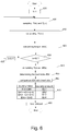
- FIG. 6 relates to a flow chart comprising the steps of the method for determining the laundry amount, which is similar to the flow chart illustrated in Figure 4 , the block of which will be indicated, where possible, with the same reference numbers which identifies corresponding blocks of the flow chart illustrated in Figure 4 .
- the method performed by the flow chart illustrated in Figure 6 differs from the method of the flow chart in Figure 4 because, instead of determining the laundry load amount QL based on torque samples Ti and Tj, which have been sampled during only a single speed commutation SCP(k), the determination of the laundry load amount QL is based on torque samples Ti(k) and Tj(k) sampled during a sequence of speed commutation phases SCP(k).
- the method further comprises the step of determining the Torque_int(k).
- the method checks if the index k is equal to a value W (block 430), and if not (N output from block 430), the method repeats the same steps disclosed in blocks 405-420, i.e. calculate the average torque TU(k), and determine the values Torque_int(k).
- the methods calculates four differential values: Torque_diff(1), Torque_diff(2), Torque_diff(3) and Torque_diff(4).
- the method further calculates the laundry load index IDX which is indicative of the laundry load within the drum (block 450) based on the values Torque_int(k) and the differential value Torque_diff(k).
- Ak and Bk are constant parameters experimentally calculated (by the Applicant) and preferably memorized in the memory device 21.
- the method may preferably compare the laundry load index IDX with one or more thresholds GHi (i comprised between 1 and d) associated with corresponding amount of laundry and determine the laundry amount based on the comparison results (block 460).
- GHi i comprised between 1 and d
- the method determines the first amount QL1 (wherein the amount is a determined weight); whereas if the laundry load index IDX is comprised in the range delimited by a first and second threshold GH1 and GH2, i.e.
- the method determine the second amount QL2; if the laundry load index IDX is comprised in the range delimited by the second and third thresholds GH2 and GH3, the third amount QL3 is determined; whereas if laundry load index IDX is greater that the threshold GH3, the fourth amount QL4 is determined.
Landscapes
- Engineering & Computer Science (AREA)
- Textile Engineering (AREA)
- Control Of Washing Machine And Dryer (AREA)
Abstract
Description
- The present invention concerns to a method for obtaining information about the amount of laundry (i.e. weight) loaded in a laundry drum of a laundry washing machine.
- Nowadays the use of laundry washing machines, both "simple" laundry washing machines (i.e. laundry washing machines which can only wash and rinse laundry) and washing-drying machines (i.e. laundry washing machines which can also dry laundry), is widespread.
- In this respect, in the present description, where not stated differently, the term "laundry treatment machine" can be referred indiscriminately to a laundry washing machine, or to a laundry washing and drying machines, or to a laundry drying machine.
- Laundry washing machines are apparatuses for removing contaminants from laundry by the action of detergent and water and may have a configuration based on a rotating drum that defines a washing chamber in which laundry items are placed for washing according to one or more washing cycles/programs.
- Generally, laundry washing machines are provided with controllers being configured to sense the amount of the laundry loaded in the rotating drum in order to set several parameters of the washing cycle, such as for example, the amount of water/detergent to be loaded, the cycle duration, and other washing parameters, based on the sensed laundry amount.
- In some kind of known laundry treatment machines, controllers are configured to perform a control method that, at the beginning of the washing cycle, indirectly estimates the amount of laundry loaded in the rotating drum based on the water absorbed by the laundry. Indeed, the amount of water loaded during the water loading phase in a washing cycle, is proportional to the amount and type of laundry loaded in the drum. Based on the amount of water adsorbed in a prefixed time, an algorithm executed by the controller estimates the laundry quantity loaded in the drum.
- This method has the problem to take long time, i.e. several minutes, to complete the estimation of the laundry load. Indeed the method may estimate the load, only after completion of the water loading procedure of the washing cycle, that generally takes up more than 15 minutes.
- Furthermore, the accuracy of the estimation is low because it strongly depends on the water absorbing degree of the fabric/textile of the loaded laundry. Laboratory test made by Applicant demonstrated, for example, that two kg of sponge laundry absorbs as much water as five kg of cotton laundry.
- It is therefore evident that kind of fabric/textile may strongly affect the accuracy of the estimation and, in some cases/conditions, provides completely wrong indication, unless the algorithms makes appropriate corrections to the estimated load value according to the kind of the fabric/textile, i.e. by considering the selected cycle.
- However such solutions, on one side, causes the machine to performs complex algorithms and, on the other side, is limited to washing programs associated to a specific kind of fabric/textile. Indeed, remaining washing programs, such as many general washing programs frequently used by users, do not contain specific information about the fabric/textile of the loaded laundry. Moreover, this solution is affected by error due to wrong selections of the washing programs made by users.
- It is further prior art to determine the amount of laundry load by performing a different procedure, which is essentially based on the time dependence of the electric power supplied by the electric motor that drives the drums, operating in a generator mode, during a revolution of the rotating drum. In this regards, for example,
US 9, 096,964 B2 - It is the aim of the present invention to provide a method for determining the laundry load, which is simple, cheap and quick, and further improves the precision compared with the above mentioned methods.
- It is thus the object of the present invention to provide a solution which allows achieving the objectives indicated above.
- According to the present invention, it is provided a method for determining a laundry load of a laundry treating machine, said laundry treating machine comprises: an outer casing, a laundry treating group which is placed inside said outer casing and comprises, in turn, a rotatable drum structured for housing the laundry to be treated, an electric motor for rotating said drum, said method being characterized by comprising the steps of: controlling the electric motor to cause said drum to change the rotational speed according to a prefixed reference speed profile comprising at least an acceleration ramp, wherein the drum is accelerated from a low speed to a prefixed high speed and at least a constant speed phase wherein the drum speed is maintained about said high speed, sampling first torque values generated by said electric motor during said acceleration ramp according to a prefixed first sample time, sampling second torque values generated by said motor during said constant speed phase according to a prefixed second sample time, calculating a third value, which is indicative of an average torque being calculated, in turn, on the basis of said second torque values, determining a fourth value by performing an integral function with respect to said first torque values and said the third value, determining the amount of laundry load on the basis of at least said fourth value.
- Preferably, said prefixed reference speed profile further comprises a deceleration ramp wherein said drum is decelerated from said high speed to said low speed; said constant speed phase being performed immediately after said acceleration ramp and immediately before said deceleration ramp.
- Preferably, said fourth value is determined by performing said integral function with respect to said first torque values subtracted of said the third value.
- Preferably, said fourth value is calculated according to the following equation:

- Wherein Ti are the torque values sampled during said acceleration ramp at instants i, N is the number of torque values sampled during said acceleration ramp, TU is the average torque calculated during said constant speed phase, Δta is the first sample time. Preferably, said fourth value is calculated according to the following equation:

- Preferably, the method further comprises the steps of: determining a load index value based on said fourth value and determining the amount of the laundry load based on said index value.
- Preferably, the load index value is determined based on the following equation IDX=A1* Torque_int; wherein A1 is a constant parameter experimentally calculated and Torque_int is said fourth value.
- Preferably, said reference speed profile comprises a sequence of drum speed commutations, wherein each speed commutation comprises said acceleration ramp, said deceleration ramp and said constant speed phase; for each of said speed commutations, the method comprises the steps of: sampling said first torque values generated by said motor during said acceleration ramp according to said first sample time, sampling said second torque values generated by said motor during said constant speed phase according to said second sample time, calculating said third value, which is indicative of an average torque being calculated, in turn, on the basis of said second torque values, determining said fourth value by performing an integral function with respect to said first torque values and said third value, the method further comprising the steps of: calculating a fifth value which is indicative of the arithmetic mean of said fourth values; determining the amount of laundry load on the basis of differential values, calculated by subtracting said fifth value from said fourth values.
- Preferably, said fourth value is determined by performing said integral function with respect to said first torque values subtracted of said the third value.
- Preferably said fifth value is calculated according to the following equation:

- Preferably said differential values are calculated according to the following equation:

- Wherein W is the number of speed commutations, Torque_int(k) are fourth values associated with the commutation phases.
- Preferably the method further comprises the steps of: determining a load index value based on said fourth values and said differential values; determining the amount of the laundry load based on said index value.
- Preferably, the method comprises the steps of comparing said laundry load index with one or more prefixed thresholds associated with respective amounts of laundry, and determine the laundry amount based on the comparison results.
- Preferably, said second sample time of said second torque values generated by said electric motor during said constant speed phase is comprised between about 0,1*10-3 s and about 50*10-3 s.
- Preferably, said second sample time of said second torque values generated by said electric motor during said constant speed phase is about 10*10-3 s.
- Preferably, said first sample time of said first torque values generated by said electric motor during said acceleration ramp is comprised between about 0,1*10-3 s and 20*10-3 s.
- Preferably, said first sample time of said first torque values generated by said motor during said acceleration ramp) is about 10*10-3 s.
- Preferably, said constant speed phase has a duration of a prefixed time corresponding about the time spent by said drum to perform a prefixed number of whole revolutions at said high speed.
- Preferably, said prefixed time corresponds to the time spent by the drum to perform two whole revolutions at said high speed.
- The present invention further relates to a laundry treatment machine comprising: an outer casing, a laundry treating group which is placed inside said outer casing and comprises, in turn, a rotatable drum structured for housing the laundry to be treated, an electric motor for rotating said drum, characterized by comprising electronic control circuit configured to: control the electric motor to cause said drum to change the rotational speed according to a prefixed reference speed profile comprising at least an acceleration ramp, wherein said drum is accelerated from a low speed to a prefixed high speed and at least a constant speed phase wherein the drum speed is maintained about said high speed, sample first torque values generated by said motor during said acceleration ramp according to a prefixed first sample time, sample second torque values generated by said motor during said constant speed phase according to a prefixed second sample time, calculate a third value, which is indicative of an average torque being calculated, in turn, on the basis of said second torque values, determine a fourth value by performing an integral function with respect to said first torque values and said third value, determine the amount of laundry load on the basis of at least said fourth value.
- Preferably, the electronic control circuit is further configured to control the electric motor so that said prefixed reference speed profile further comprises a deceleration ramp wherein said drum is decelerated from said high speed to said low speed; said constant speed phase being performed immediately after said acceleration ramp) and immediately before said deceleration ramp.
- Preferably, the electronic control circuit is further configured to calculate said fourth value by performing said integral function with respect to said first torque values subtracted of said the third value.
- Preferably, said electronic control circuit is further configured to calculate said fourth value according to the following equation:

- Wherein Ti are the torque values sampled during said acceleration ramp at instants i, N is the number of torque values sampled during said acceleration ramp, TU is the average torque calculated during said constant speed phase, Δta is the first sample time. Preferably, said fourth value is calculated according to the following equation:

- Preferably, said electronic control circuit is further configured to calculate a load index value based on said fourth value; and determine the amount of the laundry load based on said index value.
- Preferably, the load index value is determined based on the following equation IDX=A1* Torque_int; wherein A1 is a constant parameter experimentally calculated and Torque_int is said fourth value.
- Preferably, said reference speed profile comprises a sequence of drum speed commutations, wherein each speed commutation comprises said acceleration ramp, said deceleration ramp and said constant speed phase; for each of said speed commutations, the said electronic control circuit is further configured to: sample said first torque values generated by said motor during said acceleration ramp according to said first sample time, sample said second torque values generated by said motor during said constant speed phase according to said second sample time, calculating said third value, which is indicative of an average torque being calculated, in turn, on the basis of said second torque values, determine said fourth value by performing an integral function with respect to said first torque values and the third value, calculate a fifth value which is indicative of the arithmetic mean of said fourth values; determine the amount of laundry load on the basis of differential values, calculated by subtracting said fifth value from said fourth values.
- Preferably, said fourth value is determined by performing said integral function with respect to said first torque values subtracted of said the third value.
- Preferably said fifth value is calculated according to the following equation:

- Wherein W is the number of speed commutations, Torque_int(k) are the fourth values associated with the respective commutation phases.
- Preferably said differential values are calculated according to the following equation:

- Wherein W is the number of speed commutations, Torque_int(k) are fourth values associated with the commutation phases SCP(k).
- Preferably, said electronic control circuit is further configured to determine a load index value based on said fourth values and said differential values; determine the amount of the laundry load based on said index value.
- Preferably, said electronic control circuit is further configured to compare said laundry load index with one or more prefixed thresholds associated with respective amounts of laundry, and determine the laundry amount based on the comparison results. Preferably, said second sample time of said second torque values generated by said electric motor during said constant speed phase is comprised between about 0,1*10-3 s and about 50*10-3 s.
- Preferably, said second sample time of said second torque values generated by said electric motor during said constant speed phase is about 10*10-3 s.
- Preferably, said first sample time of said first torque values generated by said electric motor during said acceleration ramp is comprised between about 0,1*10-3 s and 20*10-3 s.
- Preferably, said first sample time of said first torque values generated by said motor during said acceleration ramp is about 10*10-3 s.
- Preferably, said constant speed phase has a duration of a prefixed time corresponding about the time spent by said drum to perform a prefixed number of whole revolutions at said high speed.
- Preferably, said prefixed time corresponds to the time spent by the drum to perform two whole revolutions at said high speed.
- Further characteristics and advantages of the present invention will be highlighted in greater detail in the following detailed description of some of its preferred embodiments, provided with reference to the enclosed drawings. In the drawings, corresponding characteristics and/or components are identified by the same reference numbers. In particular:
-
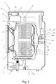
Figure 1 shows a schematic cross section, with parts removed for clarity, of a laundry washing machine made according to the present invention; -
Figure 2 is a schematic of a control system of the circuit arrangement of the laundry washing machine illustrated inFigure 1 ; -
Figure 3 is a flow chart illustrating the operations of the motor for determining the amount of laundry load in the rotating drum, in accordance with the present invention; -
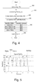
Figure 4 is a flow chart illustrating the steps performed by the method for determining the amount of laundry load in the rotating drum, in accordance with a first embodiment of the present invention; -
Figure 5 illustrates a chart of the reference speed profile and the torque provided to the drum by the motor when the drum rotates according to the reference speed profile; whereas -
Figure 6 is a flow chart illustrating the steps performed by the method for determining the amount of laundry load in the rotating drum in accordance with a second embodiment of the present invention. - The method of the present invention has proved to be particularly advantageous because allowing to quickly determine the amount of laundry load without additional electrical components in the machine, by using the motor torques samples, according to a convenient sample time, both during acceleration ramp and during a speed constant phase of the drum, following the acceleration ramp.
- With reference to
Figure 1 ,number 1 indicates as a whole a laundry washing machine comprising a preferably, though not necessarily, parallelepiped-shapedouter box casing 2 resting on the floor; a laundry washing group which is placed within saidcasing 2 and comprises preferably in turn a substantially bell-shapedlaundry washing tub 3 suspended in floating manner insidecasing 2 via a suspension system comprising a number of coil springs 4 (only one illustrated inFigure 1 ) preferably, though not necessarily, combined with one or more vibration dampers 5 (only one shown inFigure 1 ) and a substantially bell-shapedrotating drum 6 for housing the laundry QL to be washed and/or dried, and which is fixed in axially rotating manner insidewashing tub 3 for rotating about a longitudinal axis L. - As can be appreciated, the present invention can be conveniently applied to any kind of laundry treatment machines, like for example laundry washing machine (washing machine) and washing and drying machines (called also washer-driers) or laundry drying machines (called also drier), wherein one or more steps of introducing water and/or steam and/or hot/cool air inside a laundry tub is required.
- In the example illustrated in
Figure 1 , thelaundry washing machine 1 is a front loading laundry washing machine. The present invention has proved to be particularly successful when applied to front loading laundry washing machines. It should in any case be understood that the present invention is not limited to this type of application. On the contrary, the present invention can be usefully applied to different types of laundry washing machines, for example top loading laundry washing machines or top loading laundry washing and drying machines. - According to the exemplary embodiment, the
laundry washing tub 3 is suspended in floating manner inside thecasing 2, with the front opening of thelaundry washing tub 3 directly faced to a laundry loading and unloadingopening 2a formed in the front face ofcasing 2.Rotating drum 6, in turn, is housed intolaundry washing tub 3 so as that its longitudinal axis L is preferably oriented substantially horizontally, and coincides with the longitudinal axis oflaundry washing tub 3. It is understood that in alternative embodiment not shown, rotation axis L may be vertical or inclined. - In the exemplary embodiment illustrated in
Figure 1 , the front opening ofwashing tub 3 is connected to opening 2a on the front face ofcasing 2 via a cylindrical elastic-deformable bellows 8, and thewashing machine 1 is also provided with adoor 9 which is preferably hinged to the front face ofcasing 2 to rotate to and from a rest position (illustrated inFigure 1 ) in whichdoor 9 closes opening 2a ofcasing 2 to sealwashing tub 3. - As illustrated in the exemplary embodiment of
Figure 1 , thelaundry washing machine 1 may preferably, although not necessary, comprise a liquid supply assembly (not illustrated) designed for supplying water to thewashing machine 1 to use in washing laundry during a cycle of operation. For example the liquid supply assembly may comprise a source of water, such as a household water supply and may include one or more conducts and electric-controlled valves for controlling the flow of water directed preferably towards thelaundry washing tub 3 androtating drum 6 across the conducts. Thelaundry washing machine 1 may preferably, although not necessary, comprise a detergent dispensing apparatus 10 (only partially illustrated inFigure 1 ) for dispensing detergent to thedrum 6/tub 3 to be used in washing the laundry according to a selected washing program. Thedetergent dispensing apparatus 10 may comprise a dispenser which may be a single use dispenser, a bulk dispenser or a combination of a single and bulk dispenser. Regardless of the type of dispenser used, the dispenser may be configured to dispense detergent directly to thelaundry washing tub 3 or mixed with water from thedetergent dispensing apparatus 10 through a dispensing outlet conduit (not illustrated). - As illustrated in the exemplary embodiment of
Figure 1 , thelaundry washing machine 1 may further comprise adrain apparatus 13 which is designed to drain liquid from thewashing machine 1, and preferably, although not necessarily, a heating system (not illustrated) for heating the liquid (water) and/or air to be supplied to thetub 3. According to a preferred embodiment illustrated inFigure 1 , thelaundry washing machine 1 is further provided with adrive apparatus 15, which is designed to rotate thedrum 6 within thetub 3. Thedrive apparatus 15 may comprise anelectric motor 16 for rotating thedrum 6 around the axis L. - According to the exemplary embodiment illustrated in
Figure 1 , theelectric motor 16 may be directly coupled with thedrum 6 through a drive shaft to rotate thedrum 6 around the rotational axis L. Alternately, themotor 16 may be coupled to thedrum 6 through a belt (not illustrated) and a drive shaft to rotate thedrum 6, as is known in the art. Theelectric motor 16 may be a three-phases or bi-phases motor, having astator 16a and arotor 16b. A non-limiting example ofelectric motor 16 may be a permanently excited synchronous motor or an asynchronous motor or a brushless direct current motor or an induction motor or any similar motor. Theelectric motor 16 is designed to rotationally drive thedrum 6 at various speeds in either rotational direction. - According to a preferred embodiment illustrated in
Figures 1 and2 , thelaundry washing machine 1 is further provided with a control system for controlling the operation of thelaundry washing machine 1 in order to perform one or more laundry washing/drying programs selected by users. The control system may be provided with a electric/electronic control circuit 18 located within thecasing 2 and auser interface 19, that is electrically coupled with thecontrol circuit 18. Theuser interface 19 may include a control panel with one or more displays, touch screens dials, knobs, switches, and the like for communicating with users, such as to receive input and provide output. An user may enter in theuser interface 19 different types of information such for example, washing cycle parameters, washing cycle programs, etc.... - The
control circuit 18 may comprise one or more controllers configured to control the operating of the machine and any of the electric/electronic components/circuit/boards of thelaundry washing machine 1 according to the method hereinafter disclosed. Preferably, although not necessarily, thecontrol circuit 18 may comprise one or more microprocessor-based controller configured to implement control software and/or sends/receives one or more electrical signals to/from each of the various electric/electronic components/circuits/boards to effect the control software. Thecontrol circuit 18 may be electrically coupled with one or more components of thelaundry washing machine 1 for communicating with and controlling the operation of the components in order to perform a washing program. Thecontrol circuit 18 may also be coupled with one or more sensors provided in one or more of the systems of thelaundry washing machine 1 to receive input from the sensors. - According to the present invention, non-limiting examples of sensors which may be electrically coupled with the
control circuit 18 may preferably, although not necessary, comprise, amotor torque sensor 20 which is configured to provide a torque output signal being indicative of the torque generated by theelectric motor 16, which corresponds about to the torque applied to thedrum 6 by saidmotor 16. - It is understood that the
motor torque sensor 20 provides a signal value being a function of the inertia of therotating drum 6 and the laundry load. Themotor torque sensor 20 may also comprise a motor controller or similar data output on themotor 16 that provides data communication with themotor 16 and outputs motor characteristic information, generally in the form of an analog or digital signal, to thecontrol circuit 18 that is indicative of the applied torque. - The
control circuit 18 may use the motor characteristic information to determine the torque applied by themotor 16 using software that may be stored in amemory device 21. Specifically, themotor torque sensor 20 may be any suitable sensor, such as a voltage or current sensor, for outputting a current or voltage signal indicative of the current or voltage supplied to themotor 16 to determine the torque applied by themotor 16. Additionally, themotor torque sensor 20 may be a physical sensor or may be integrated with the motor and combined with the capability of thecontrol circuit 18, may function as a sensor. For example, motor characteristics, such as current, voltage, torque etc., may be processed such that the data provides information in the same manner as a separate physical sensor. - According to the preferred embodiment illustrated in
Figure 1 , thelaundry washing machine 1 may preferably comprise aspeed sensor 22 which may be positioned in any suitable location for detecting and providing a speed output indicative of a rotational speed of thedrum 6. - Such a
speed sensor 22 may be any suitable speed sensor capable of providing an output indicative of the speed of thedrum 16. It is also contemplated that the rotational speed of thedrum 6 may also be determined based on a motor speed; thus, thespeed sensor 22 may include a motor speed sensor for determining a speed output indicative of the rotational speed of themotor 16. The motor speed sensor may be a separate component, or may be integrated directly into themotor 16. Regardless of the type of speed sensor employed, or the coupling of thedrum 6 with themotor 16, thespeed sensor 22 may be configured to cause thecontrol circuit 18 to determine the rotational speed of thedrum 6 from the rotational speed of themotor 16. The above describedwashing machine 1 may be used to implement one or more embodiments of the invention. The embodiments of the method of the invention may be used to determine the amount of laundry load QL in thedrum 6. - The control system may be further provided with a
motor controller 23 which is electrically coupled with thecontrol circuit 18 and with themotor 16 to control the later according to the washing program to be performed. - According to a preferred embodiment illustrated in
Figure 2 , themotor controller 23 may comprise a rectifyingunit 24 for converting an AC power source into a DC voltage and outputting the converted DC voltage, and an energy storage circuit which, in the illustrated example, comprise a DC orbulk capacitor circuit 25 for smoothing the DC voltage which was rectified by the rectifyingunit 24. However, it is understood that the present invention is not limited to thebulk capacitor circuit 25. On the contrary,motor controller 23 may comprise, in alternative, or in addition to, thebulk capacitor circuit 25, one or more electrical batteries (not illustrated) or similar apparatus configured to storage the electrical energy. It follows that the operations concerning thebulk capacitor circuit 25, performed by the method according to the next description, may be performed likewise for the electrical batteries. - The
motor controller 23 further comprise apower inverter device 26 for driving themotor 16 by means of the DC voltage, which was transferred by the rectifyingunit 24. Themotor controller 23 may further comprise a voltage-sensingunit 27 for sensing/measuring the voltage of the energy storage circuit (which in the illustrated example is the DC/bulk capacitor circuit 25), during the operating of themotor 16, and provide to the control circuit 18 a sensed voltage generated due to the sensed results. Themotor controller 23 may further comprise acontrol module 28, i.e. a microcomputer which controls thepower inverter device 26 so as to pilot themotor 16 based on commands provided by thecontrol circuit 18. - A detailed description of other components present in the
laundry washing machine 1 will be omitted because it is considered to be unnecessary for the present invention. Referring now toFigures 3 and4 , flow charts of a method for determining the amount of laundry load QL in thedrum 6 are illustrated. - The sequence of steps illustrated for this method is for illustrative purposes only, and is not meant to limit the method in any way as it is understood that the steps may proceed in a different logical order or additional or intervening steps may be included without detracting from the invention. The method may be implemented in any suitable manner, such as automatically, as a stand-alone phase or cycle of operation or as a phase of an operation cycle of the
washing machine 1. - Before explaining the method, it is hereby provided a list of symbols/signs used in the present description and their meaning in order to improve the clarity of the present invention.
- SCP(k) = speed commutation phase;
- Ra(k)=acceleration ramp phase;
- Rd(k)=deceleration ramp phase;
- S(k)=constant speed phase;
- Δts = duration of the constant speed phase S(k);
- B1= first rotational drum speed;
- B2= second rotational drum speed;
- k= commutation counter;
- i=torque index;
- j=torque index;
- Ti= samples of motor torque during the acceleration ramp Ra(k) (k comprised between 1 and N);
- N= number of motor torque samples during the acceleration ramp Ra(k);
- Tj= sample of motor torque during the constant speed phase S(k);
- M= number of motor torque samples during the constant speed phase S(k);
- RN= number of revolutions of the drum;
- Δta=torque sample time during the acceleration ramp Ra(k);
- Δtb=torque sample time during the constant speed phase S(k);
- W= number of speed commutation phases to be performed during a reference speed profile;
- TU=average torque value;
- Torque_int= integral function with respect to said the torque values Ti and preferably, with TU;
- Torque_diff= differential values.
-
Figure 3 is a flow chart comprising some operation of themotor 16 for determining the amount of laundry load QL of thelaundry washing machine 1 in accordance with one embodiment of the present invention, whereasFigure 4 is a flow chart illustrating remaining operations performed by the method for determining the amount of laundry load QL of alaundry washing machine 1 in accordance with an embodiment of the present invention. - More in detail, the flow chart in
Figure 3 comprises the steps performed by the method to drive themotor 16 in order to rotate thedrum 6 according to a prefixed reference speed profile (for example performed as inFigure 5 ), whereas the flow chart ofFigure 4 comprises the steps implemented by the method to calculate the amount of laundry load QL in thedrum 6, when the speed of thedrum 6 is varied according to said reference speed profile. - It should in any case be understood that the present invention is not limited to the reference speed profile corresponding to the "drum" speed, but according to a different embodiment it may be envisaged to use, in alternative, a reference speed profile corresponding to the "motor" speed.
- With reference to the exemplary embodiment illustrated in
Figure 5 , the prefixed reference speed profile may comprise one or more speed variations of thedrum 6, hereinafter called "speed commutations phases" SCP(k) to which the following description will make explicit reference without thereby losing generality. Each speed commutation phase SCP(k) comprises: an acceleration ramp phase Ra(k), a deceleration ramp phase Rd(k), and a constant speed phase S(k) which is located between the acceleration ramp Ra(k) and the corresponding deceleration ramp Rd(k). - Preferably, the rotational speed of the
drum 6 during the acceleration Ra(k)/deceleration ramps Rd(k) varies between a determined first rotational speed B1 and a second rotational speed B2 which is greater than the first speed, i.e. B2>B1. The reference speed of thedrum 6 during the constant speed phase S(k) is maintained approximately at the second rotational speed B2. - According to the preferred embodiment, the number of speed commutation phases SCP(k) of the reference speed profile may be conveniently comprised between one and six commutation phases SCP(k). Preferably, the method may perform four commutation phases SCP(k).
- Preferably, during the acceleration ramp phase Ra(k), the motor may operate in a "motor mode" , whereas during the deceleration ramp Rd(k) the motor brakes the
drum 6 and operates in a "generator mode". - According to the exemplary embodiment illustrated in
Figure 5 , the first rotational speed B1 may be preferably comprised in the speed range from about 25 to 35 RPM, preferably 30 RPM, whereas the second rotational speed B2 corresponding to the reference speed may be preferably comprised in the range from about 75 to 85 RPM, preferably 80 RPM. - With reference to
Figure 5 , the speed changes of thedrum 6 during each speed commutation phase SCP(k) is advantageously equal to the speed changes of the other commutation phases SCP(k), whereas the duration of the constant speed phase S(k) is the prefixed time Δts. - The method starts at the beginning of the laundry washing cycle, with assuming that the user has placed one or more laundry items for treatment within the
drum 6, selected laundry washing program through theuser interface 19, and started of performing the selected laundry washing program. Moreover, it is assumed thatcontrol circuit 18 may preferably have performed a known draining phase/procedure in which thedrain apparatus 11 has drained remaining liquid/water present in thewashing machine 1. - In detail, the user loads the laundry and then may press start. At the beginning of the cycle, a drain pump, if present, may be preferably activated to drain the remaining water in the
washing tub 3; preferably, right after the draining phase, some movements may be performed (without loading water) to detect the amount of laundry. The information extrapolated from the movements may be used for setting some washing cycle parameters and to give some information to the customer, like estimated cycle length and/or the determined amount of laundry. - With reference to the flow chart illustrated in
Figure 3 , thecontrol circuit 18 drives themotor 16 by means of themotor controller 23 in order that the speed of thedrum 6 tracks the reference speed profile comprising one or more speed commutation phases SCP(k). Non-limiting example of the reference speed profile performed by the method, used with the only aim to improve the understanding of the present invention is illustrated inFigure 5 . - At blocks 100-160 of
Figure 3 , thecontrol circuit 18 drives themotor 16 by means of themotor controller 23 in order to preferably perform a number of the sequential speed commutations phases SCP(k) wherein, during each commutation SCP(k), thedrum 6 is: accelerated according to the acceleration ramp Ra(k), maintained at the reference speed for the prefixed time Δts and, finally, decelerated according to the deceleration ramp Rd(k). - According to an exemplary embodiment illustrated in
Figure 3 (block 100), the method may preferably comprise the steps of: setting a counter k=1 which is designed to count the speed commutation phases SCP(k), and setting an index i=1 associated with a torque samples Ti during the acceleration ramp Ra(k). - Moreover, the method may further comprise the steps of: accelerating the
drum 6 according to the acceleration ramp Ra(k)(block 110) from the first speed B1 to the second speed B2 (block 160). - While the
drum 6 is being accelerated, the motor may operate in "motor mode" and the method, i.e. thecontrol circuit 18, performs the steps of: sampling the motor torque Ti (block 120), increasing the index i=i+1 (block 130), and checking if the index i is equal to the prefixed number N (block 140), which is indicative of the maximum number of torque sampling to be performed during the acceleration ramp Ra(i). - If the index i is not equal to the prefixed number N (output N from the block 140), the method performs again, after a prefixed sampling time Δta (block 150), the sampling of the motor torque when the
drum 6 is accelerating. - More specifically, according to a preferred embodiment, the
control circuit 18 may receive one or more signals from themotor 16 and/or from themotor torque sensor 20 and determines/samples the motor torque Ti based on these electrical signals. Preferably, the signal may comprise electric values indicative of the current supplied to the motor by theinverter device 26. - Vice versa, if the sampling index i is equal to the prefixed number N (output Y from the block 140) the method stops the sampling and preferably continue to accelerate the
drum 6 until the drum speed reaches the prefixed second speed B2 (block 160). - It should be understood that present invention is not limited to a prefixed number N. Indeed, alternately, N may be indefinite and the method does not perform the
step 140 and thestep 150 follows thestep 130. The value N may be calculated based on the number of torques values sampled during the acceleration ramp Ra(i) until the drum speed reaches the prefixed second speed B2. In detail, the method may sample the motor torque Ti at prefixed sampling time Δta until the drum speed reaches the prefixed second speed B2 (block 160) and when the latter condition is meet, calculates the number N based on the index i, i.e. N=i. - When the speed of the
drum 6 reaches the second speed B2 (Outputs Y from the block 160), thecontrol circuit 18 drives themotor 16 in order to maintain thedrum 6 at the reference speed B2 for the prefixed time Δts and, during the latter, samples the motor torques Tj according to a prefixed sample time Δtb. - According to the exemplary embodiment illustrated in
Figure 3 , the method may preferably comprise the steps of: setting the index j=1 (block 170), sampling the torque Tj (block 180) according to the sample time Δtb, increasing the index j=j+1 (block 190), checking when the sampling index j reaches a prefixed number M (block 200), which is indicative of the maximum number of torque sampling to be performed during the constant speed phase S(k). - In other words, while the speed of the
drum 6 is being maintained at the reference speed B2, i.e. during the time Δts (blocks from 160 to 200), the method may repeatedly determine a value which is indicative of the motor torque Tj. - If the sampling index j is not equal to the prefixed number M (output N from the block 200), the method performs again, after the sampling time Δtb (block 210), the sampling of the motor torque during the constant speed phase S(k).
- Vice versa, if the index j is equal to the prefixed number M (output Y from the block 200), the method starts decelerating the drum 6 (block 220) until the drum speed reaches the first speed B1 (block 230). During the deceleration ramp Rd(i), the motor preferably operates in generator mode.
- When the
control circuit 18 determines that thedrum 6 rotates at the first speed B1 (outputs Y from the block 230) and thus the commutation has been completed, thecontrol circuit 18 may increase the commutation counter k=k+1 (block 240). - It should be understood that, again, the present invention is not limited to a prefixed number M. Indeed, alternately, M may be indefinite and the method does not perform the
step 200 and thestep 210 follows thestep 190. Thus, the value M is calculated based on the number of torques values repeatedly sampled during the time Δts. In detail, the method samples the motor torque Tj at prefixed sampling time Δtb until the end of the constant speed phase S(k) (Δts) and calculates the number M based on the index j, i.e. N=j. - Afterwards the method checks if the commutation counter k is equal to a value W, which is the number of speed commutation phases that the method must perform (block 250) in order to determine whether a new speed commutation phase has to be performed.
- If not (N output from block 250), the method repeats the same steps disclosed in blocks 110-250, while if yes (outputs Y from block 250), i.e. the commutation counter "k" reaches the value W, the methods performs the load estimating method according to the flow chart illustrated in
Figure 4 . - With reference to the flow chart illustrated in
Figure 4 , the method determine/calculate a value TU which is indicative of an average torque value calculated according to the motor torque samples Tj (block 300) determined during the constant speed phase S(k) of a speed commutation phase SCP(k). - For example, the value TU may be determined by performing an arithmetic mean of the measured torques values Tj. For example the method may implements the following equation:

- Preferably, the value TU may be memorized in the
memory device 21. It is understood that average torque value TU is substantially indicative of the torque needed to contrast friction of the washing machine. In detail, friction in washing machine has two sources. One may be called system friction. Because of differences in stiffeness, suspension, machine age, bearings, motor temperature, belt tension, and the like, the variation of the system friction can be significantly large between one washing machines and another. A second source of friction corresponds to friction of the laundry on the door and friction on door gasket/bellows 8. These components of friction depend on size of the laundry and its imbalance conditions in thedrum 6. - The method further comprises the step of performing an approximate integral calculus (preferably comprising a summation in the example) of the torques values Ti sampled during the acceleration ramp Ra(k) subtracted of the value TU. Preferably the method comprises the step of determining the value Torque_int according to the following equation (block 310):

- It is understood that according to the preferred embodiment of the present invention, the acceleration ramp Ra(k) and the constant speed phase S(k) may be preferably comprised in the same speed commutation phase SCP(k), wherein the constant speed phase S(k) starts directly at the end of the acceleration ramp Ra(k).
- According to an alternative embodiment, the value Torque_int is calculated based on the following equation 3) (which replaces the equation 2) :

- According to the alternative embodiment, the method may performs the following steps:
- calculating an integral function with respect to the first torque values Ti based on the following equation:
- 3a)

- 3a)
- multiplying the value TU by the number N of torque samples Ti;

- performing the difference between the value obtained by the equation 3a) and the value obtained by the equation 3b) and multiplying the difference value by prefixed sample time Δta.
- According to the preferred embodiment, the method may preferably calculate a laundry load index value IDX which is indicative of the laundry load within the
drum 6 based on the value Torque_int (block 320). - In detail, the method may preferably calculate the laundry load index value IDX by implementing the following equation:

- Wherein A1 is a constant parameter experimentally calculated (by the Applicant) and preferably memorized in the
memory device 21. - Moreover, the method may preferably compare the laundry load index IDX with one or more thresholds Thi (i comprised between 1 and d) associated with respective amount of laundry load QLi and determines/estimates the laundry amount based on the comparison results (block 330).
- With reference to the exemplary embodiment illustrated in
Figure 4 (block 340), the method may preferably comprise a number of determined threshold THi, i.e. preferably three thresholds TH1, TH2 and TH3 (i comprised between 1 and d=3). In detail, if the laundry load index IDX is lower than the first threshold TH1, i.e. IDX<TH1, the method determines the first amount QL1 (wherein the amount is a determined weight); whereas if the laundry load index IDX is comprised in the range delimited by a first and second threshold TH1 and TH2, i.e. TH1<=IDX <=TH2 the method determine the second amount QL2; if the laundry load index IDX is comprised in the range delimited by the second and third thresholds TH2 and TH3 the third amount QL3 is determined; whereas if laundry load index IDX is greater that the threshold TH3, the fourth amount QL4 is determined. - It should be understood that the estimated amount of laundry load QLi takes conveniently in to account the values estimated during the speed commutation phases.
- After determining the laundry load amount, the method preferably displays such determining/estimated value to the user by the
user interface 19 and/or preferably set several parameters of the washing cycle, such as for example, the amount of water/detergent to be loaded, the cycle duration, and other washing parameters, based on the determined laundry amount. - According to the present invention, the determined laundry amount QL may be communicated to the user by displaying a numeric value and/or by graphic representations. For example, the graphic representations may comprise one or more broken lines wherein any portion of the line may be associated to a numeric value and, in usage, is displayed (activated) based on the determined laundry amount.
- According to the present invention, the prefixed time Δts of the constant speed phase S(k) may be set according to the time spent by the
drum 6 to complete a prefixed number RN of revolutions at the reference speed B2, wherein RN is an integer number. According to an exemplary embodiment of the present invention, the prefixed number RN of revolutions at the reference speed B2 is two. In this regards it is pointed out that Applicant has found that the mean torque calculated on the basis of the torque values sampled during a time spent by the drum to complete a whole rotation is not affected from load unbalances. Indeed, during its rotation, thedrum 6 may be subjected to several fluctuations which however are distributed in opposite position one to the other, and thus tend to mutually cancel out each other in the computation of the average torque. - According to the present invention the sampling time Δta of the torque during the acceleration ramp Ra(k) is comprised in the range from about 0,1*10-3 seconds to about 20*10-3 seconds, preferably Δta is about 10*10-3 seconds, and the sampling time Δtb of the torque during the speed constant phase SPF(k) is comprised in the range from about 0,1*10-3 seconds to about 50*10-3 seconds, preferably Δtb is about 10*10-3 seconds. Applicant has found that if the sampling time of the torque (Δta, Δtb) is a multiple of the motor control loop, which may be 1*10-3 seconds when the frequency of the electrical power which supplies the motor is 50 Hz, the accuracy of the calculation of the laundry amount is increased and the sampling is easier to manage.
- The advantageous embodiment shown in
Figure 6 relates to a flow chart comprising the steps of the method for determining the laundry amount, which is similar to the flow chart illustrated inFigure 4 , the block of which will be indicated, where possible, with the same reference numbers which identifies corresponding blocks of the flow chart illustrated inFigure 4 . - The method performed by the flow chart illustrated in
Figure 6 differs from the method of the flow chart inFigure 4 because, instead of determining the laundry load amount QL based on torque samples Ti and Tj, which have been sampled during only a single speed commutation SCP(k), the determination of the laundry load amount QL is based on torque samples Ti(k) and Tj(k) sampled during a sequence of speed commutation phases SCP(k). - According to the exemplary embodiment shown in
Figure 6 , the method comprises the step of: setting the index k=1 indicating the numeric order of the commutation phase SCP(k) (block 400), sampling the motor torque Ti(k) during the acceleration ramp Ra(k) of the commutation phase SCP(k) (block 405), sampling the motor torque Tj(k) during the constant speed phase S(k) of the commutation phase SCP(k) (block 405), and calculating the value indicative of the average torque TU(k) based on motor torque Tj(k) values sampled during the constant speed phase S(k) (block 410). - The method further comprises the step of performing the approximate integral calculus (preferably summation as in the example) of the torques values Ti(k) sampled during the acceleration ramp Ra(k) of the commutation phase SCP(k) to determine a value according to the following equation:

- The method further comprises the step of determining the Torque_int(k). In detail the method performs the following equation (block 420);

- Afterwards the method checks if the index k is equal to a value W (block 430), and if not (N output from block 430), the method repeats the same steps disclosed in blocks 405-420, i.e. calculate the average torque TU(k), and determine the values Torque_int(k).
- If yes (Y output from block 430), the method calculates, for each commutation phase SCP(k), a value corresponding to the differential value Torque_diff(k) according to the following equation (block 440):

- For example, if the reference speed profile comprises four commutation phase SCP(k), the methods calculates four differential values: Torque_diff(1), Torque_diff(2), Torque_diff(3) and Torque_diff(4).
- With reference to the
Figure 6 , the method further calculates the laundry load index IDX which is indicative of the laundry load within the drum (block 450) based on the values Torque_int(k) and the differential value Torque_diff(k). - In detail, the method may preferably calculate the laundry load index value IDX by implementing the following equation:

- For example, if the reference speed profile comprises four speed commutation phases SCP(k), the laundry load index value IDX is calculated by:

- Wherein Ak and Bk are constant parameters experimentally calculated (by the Applicant) and preferably memorized in the
memory device 21. - Moreover, the method may preferably compare the laundry load index IDX with one or more thresholds GHi (i comprised between 1 and d) associated with corresponding amount of laundry and determine the laundry amount based on the comparison results (block 460).
- With reference to the exemplary embodiment illustrated in
Figure 6 (block 470), the method may preferably comprise a number of determined threshold GHi, i.e. preferably three thresholds GH1, GH2, GH3 (d=3). In detail, if the laundry load index IDX is lower than the first threshold GH1, i.e. IDX<GH1 the method determine the first amount QL1 (wherein the amount is a determined weight); whereas if the laundry load index IDX is comprised in the range delimited by a first and second threshold GH1 and GH2, i.e. GH1<=IDX <=GH2 the method determine the second amount QL2; if the laundry load index IDX is comprised in the range delimited by the second and third thresholds GH2 and GH3, the third amount QL3 is determined; whereas if laundry load index IDX is greater that the threshold GH3, the fourth amount QL4 is determined. While the present invention has been described with reference to the particular embodiments shown in the figures, it should be noted that the present invention is not limited to the specific embodiments illustrated and described herein; on the contrary, further variants of the embodiments described herein fall within the scope of the present invention, which is defined in the claims.
Claims (17)
- Method for determining a laundry load (QL) of a laundry treating machine (1), said laundry treating machine (1) comprises:an outer casing (2),a laundry treating group which is placed inside said outer casing and comprises, in turn, a rotatable drum (6) structured for housing the laundry to be treated,an electric motor (16) for rotating said drum (6),said method being characterized by comprising the steps of:controlling the electric motor (16) to cause said drum to change the rotational speed according to a prefixed reference speed profile comprising at least an acceleration ramp (Ra(i)), wherein the drum is accelerated from a low speed (B1) to a prefixed high speed (B2) and at least a constant speed phase S(k) wherein the drum speed is maintained about said high speed (B2),sampling first torque values (Ti) generated by said electric motor (16) during said acceleration ramp Ra(i) according to a prefixed first sample time (Δta),sampling second torque values (Tj) generated by said motor (16) during said constant speed phase S(k) according to a prefixed second sample time (Δtb),calculating a third value (TU), which is indicative of an average torque being calculated, in turn, on the basis of said second torque values (Tj),determining a fourth value (Torque_int) by performing an integral function with respect to said first torque values (Ti) and said the third value (TU),determining the amount of laundry load (QL) on the basis of at least said fourth value (Torque_int).
- Method according to claim 1, wherein said prefixed reference speed profile further comprises a deceleration ramp (Rd(k)) wherein said drum (6) is decelerated from said high speed (B2) to said low speed (B1); said constant speed phase S(k) being performed immediately after said acceleration ramp (Ra(i)) and immediately before said deceleration ramp (Rd(k)).
- Method according to claims 1 or 2, wherein said fourth value (Torque_int) is determined by performing said integral function with respect to said first torque values (Ti) subtracted of said the third value (TU).
- Method according to any of the previous claims, wherein said fourth value (Torque_int) is calculated according to the following equation:

- Method according to claim 1, wherein said fourth value (Torque_int) is calculated according to the following equation:

- Method according to any of the previous claims, comprising the steps of:- determining a load index value (IDX) based on said fourth value (Torque_int);- determining the amount (QL) of the laundry load based on said index value (IDX).
- Method according to claim 6, wherein said load index value (IDX) is determined based on the following equation:

- Method according to claim 2, wherein said reference speed profile comprises a sequence of drum speed commutations (SCP(k)), wherein each speed commutation (SCP(k)) comprises said acceleration ramp (Ra(i)), said deceleration ramp ((Rd(k)) and said constant speed phase (S(k));
for each of said speed commutations (SCP(k)), the method comprises the steps of:sampling said first torque values (Ti) generated by said motor (16) during said acceleration ramp (Ra(i)) according to said first sample time (Δta),sampling said second torque values (Tj) generated by said motor (16) during said constant speed phase (S(k)) according to said second sample time (Δtb),calculating said third value (TU), which is indicative of an average torque being calculated, in turn, on the basis of said second torque values (Tj),determining said fourth value by performing an integral function with respect to said first torque values (Ti) and the third value (TU),the method further comprising the steps of:calculating a fifth value which is indicative of the arithmetic mean of said fourth values;determining the amount of laundry load (QL) on the basis of differential values (Torque_diff), calculated by subtracting said fifth value from said fourth values (Torque_int(k)). - Method according to claim 8, wherein said fourth value is determined by performing said integral function with respect to said first torque values (Ti) subtracted of said the third value (TU).
- Method according to claim 8, wherein said fifth value is calculated according to the following equation:

- Method according to claim 10, wherein said differential values (Torque_diff(k)) are calculated according to the following equation:

- Method according to claim 10, comprising the steps of:- determining a load index value (IDX) based on said fourth values and said differential values;- determining the amount of the laundry load based on said index value (IDX).
- Method according to claims 6 or 12, comprising the steps of comparing said laundry load index (IDX) with one or more prefixed thresholds (Thi)(Ghi) associated with respective amounts of laundry (QLi), and determine the laundry amount (QL) based on the comparison results.
- Method according to any of the previous claims, wherein said second sample time (Δtb) of said second torque values (Tj) generated by said electric motor (16) during said constant speed phase (S(k)) is comprised between about 0,1*10-3 s and about 50*10-3 s.
- Method according to any of the previous claims, wherein said second sample time (Δtb) of said second torque values (Tj) generated by said electric motor (16) during said constant speed phase (S(k)) is about 10*10-3 s.
- Method according to any of the previous claims, wherein said first sample time (Δta) of said first torque values (Ti) generated by said electric motor (16) during said acceleration ramp (Ra(k)) is comprised between about 0,1*10-3 s and 20*10-3 s.
- Laundry treatment machine (1) comprising:an outer casing (2),a laundry treating group which is placed inside said outer casing (2) and comprises,in turn, a rotatable drum (6) structured for housing the laundry to be treated,an electric motor (16) for rotating said drum (6),characterized by comprising electronic control circuit (18) configured to:control the electric motor (16) to cause said drum (6) to change the rotational speed according to a prefixed reference speed profile comprising at least an acceleration ramp (Ra(i)), wherein said drum (6) is accelerated from a low speed (B1) to a prefixed high speed (B2) and at least a constant speed phase (S(k)) wherein the drum speed is maintained about said high speed (B2),
sample first torque values (Ti) generated by said motor (16) during said acceleration ramp Ra(i) according to a prefixed first sample time (Δta),sample second torque values (Tj) generated by said motor (16) during said constant speed phase according to a prefixed second sample time (Δtb),calculate a third value (TU), which is indicative of an average torque being calculated, in turn, on the basis of said second torque values (Tj),determine a fourth value by performing an integral function with respect to said first torque values (Ti) and said third value (TU),determine the amount of laundry load (QL) on the basis of at least said fourth value (Torque_int).
Priority Applications (4)
| Application Number | Priority Date | Filing Date | Title |
|---|---|---|---|
| CN201680058476.8A CN108138424B (en) | 2015-10-26 | 2016-10-26 | Method for estimating the amount of laundry loaded in a rotating drum of a washing machine |
| PCT/EP2016/075757 WO2017072156A1 (en) | 2015-10-26 | 2016-10-26 | Method for estimating the amount of laundry loaded in a rotating drum of a laundry washing machine |
| US15/767,270 US10619286B2 (en) | 2015-10-26 | 2016-10-26 | Method for estimating the amount of laundry loaded in a rotating drum of a laundry washing machine |
| AU2016345527A AU2016345527B2 (en) | 2015-10-26 | 2016-10-26 | Method for estimating the amount of laundry loaded in a rotating drum of a laundry washing machine |
Applications Claiming Priority (1)
| Application Number | Priority Date | Filing Date | Title |
|---|---|---|---|
| EP15191511.3A EP3162942B1 (en) | 2015-10-26 | 2015-10-26 | Laundry treating machine and method for determining the amount of laundry loaded in a rotating drum of a laundry treating machine |
Publications (2)
| Publication Number | Publication Date |
|---|---|
| EP3162943A1 true EP3162943A1 (en) | 2017-05-03 |
| EP3162943B1 EP3162943B1 (en) | 2022-12-21 |
Family
ID=54360252
Family Applications (2)
| Application Number | Title | Priority Date | Filing Date |
|---|---|---|---|
| EP15191511.3A Active EP3162942B1 (en) | 2015-10-26 | 2015-10-26 | Laundry treating machine and method for determining the amount of laundry loaded in a rotating drum of a laundry treating machine |
| EP16167014.6A Active EP3162943B1 (en) | 2015-10-26 | 2016-04-26 | Method for estimating the amount of laundry in a rotating drum of a laundry washing machine |
Family Applications Before (1)
| Application Number | Title | Priority Date | Filing Date |
|---|---|---|---|
| EP15191511.3A Active EP3162942B1 (en) | 2015-10-26 | 2015-10-26 | Laundry treating machine and method for determining the amount of laundry loaded in a rotating drum of a laundry treating machine |
Country Status (6)
| Country | Link |
|---|---|
| US (1) | US10619286B2 (en) |
| EP (2) | EP3162942B1 (en) |
| CN (1) | CN108138424B (en) |
| AU (1) | AU2016345527B2 (en) |
| PL (1) | PL3162943T3 (en) |
| WO (1) | WO2017072156A1 (en) |
Cited By (3)
| Publication number | Priority date | Publication date | Assignee | Title |
|---|---|---|---|---|
| EP3715521A1 (en) | 2019-03-27 | 2020-09-30 | Electrolux Appliances Aktiebolag | Laundry treatment appliance with dry estimate of the amount of laundry load |
| IT202100007244A1 (en) * | 2021-03-25 | 2022-09-25 | Candy Spa | WASHING MACHINE WITH DETERMINATION OF THE MASS OF LINEN |
| RU2855883C2 (en) * | 2021-03-25 | 2026-02-04 | Канди С.П.А. | Washing machine with laundry mass determination function |
Families Citing this family (19)
| Publication number | Priority date | Publication date | Assignee | Title |
|---|---|---|---|---|
| CN107059326B (en) * | 2017-05-31 | 2020-04-03 | 广东威灵电机制造有限公司 | Inertia detection method of washing machine, washing machine and storage medium |
| US10612175B2 (en) | 2017-09-28 | 2020-04-07 | Midea Group Co., Ltd. | Automatic color composition detection for laundry washing machine |
| CN108385329B (en) * | 2018-01-30 | 2023-09-22 | 无锡小天鹅电器有限公司 | Washing machine and method and device for detecting load weight of washing machine |
| CN108755009B (en) * | 2018-06-14 | 2021-02-23 | 广东威灵电机制造有限公司 | Operation control method, system, device and storage medium for clothes processing device |
| EP3608466B1 (en) * | 2018-08-09 | 2024-05-15 | E.G.O. Elektro-Gerätebau GmbH | Laundry treating device and method for its operation |
| WO2020071739A1 (en) * | 2018-10-02 | 2020-04-09 | Samsung Electronics Co., Ltd. | Washing machine |
| US11639571B2 (en) * | 2020-03-27 | 2023-05-02 | Haier Us Appliance Solutions, Inc. | System and method for determining dry load weight within a washing machine appliance |
| US11371175B2 (en) | 2020-06-04 | 2022-06-28 | Midea Group Co., Ltd. | Laundry washing machine with dynamic selection of load type |
| US11866868B2 (en) | 2020-12-18 | 2024-01-09 | Midea Group Co., Ltd. | Laundry washing machine color composition analysis with article alerts |
| US11898289B2 (en) | 2020-12-18 | 2024-02-13 | Midea Group Co., Ltd. | Laundry washing machine calibration |
| US11773524B2 (en) | 2020-12-18 | 2023-10-03 | Midea Group Co., Ltd. | Laundry washing machine color composition analysis during loading |
| US12221736B2 (en) | 2021-12-10 | 2025-02-11 | Midea Group Co., Ltd. | Laundry washing machine with dynamic drain system |
| US12264425B2 (en) | 2021-12-10 | 2025-04-01 | Midea Group Co., Ltd. | Laundry washing machine with dynamic spin system |
| US12252837B2 (en) | 2022-01-05 | 2025-03-18 | Haier Us Appliance Solutions, Inc. | Dryer appliance load detection |
| US12241195B2 (en) | 2022-05-24 | 2025-03-04 | Haier Us Appliance Solutions, Inc. | Washing machine appliance load size detection using power and balance |
| US12139836B2 (en) | 2022-06-28 | 2024-11-12 | Midea Group Co., Ltd. | Laundry washing machine with dynamic rinse system |
| US12054873B2 (en) | 2022-07-11 | 2024-08-06 | Haier Us Appliance Solutions, Inc. | Washing machine appliance and augmented reality control features |
| KR20250152401A (en) * | 2024-04-16 | 2025-10-23 | 삼성전자주식회사 | A washing device having a filter device and a generator |
| US12244249B1 (en) * | 2024-09-11 | 2025-03-04 | Wolong Electric Group Co., Ltd. | System and method for advanced electronic starting switch assembly for split-phase induction motors for domestic dryers |
Citations (5)
| Publication number | Priority date | Publication date | Assignee | Title |
|---|---|---|---|---|
| DE19857903A1 (en) * | 1997-12-16 | 1999-06-17 | Miele & Cie | Determining volume of laundry in washing machine or dryer drum |
| DE10305675B3 (en) * | 2003-02-12 | 2004-05-27 | Diehl Ako Stiftung & Co. Kg | Drum loading determination method for laundry machine using measured electrical power requirements of electric drive motor for loaded laundry drum |
| US20110005339A1 (en) * | 2009-07-09 | 2011-01-13 | Whirlpool Corporation | Method and apparatus for determining laundry load |
| EP2837732A1 (en) * | 2013-08-14 | 2015-02-18 | LG Electronics, Inc. | Laundry treating apparatus and method for controlling the same |
| US9096964B2 (en) | 2009-03-02 | 2015-08-04 | BSH Hausgeräte GmbH | Method and circuit arrangement for determining the load and/or unbalance of a laundry drum of a washing machine |
Family Cites Families (8)
| Publication number | Priority date | Publication date | Assignee | Title |
|---|---|---|---|---|
| JPH11492A (en) * | 1997-06-12 | 1999-01-06 | Yaskawa Electric Corp | Washing machine |
| KR100348626B1 (en) * | 2000-09-28 | 2002-08-13 | 엘지전자주식회사 | Dection of the weight of a washing machine |
| JP3962668B2 (en) * | 2002-09-24 | 2007-08-22 | 株式会社東芝 | Drum washing machine |
| KR100504486B1 (en) * | 2002-12-10 | 2005-08-03 | 엘지전자 주식회사 | Method for Detecting Amount of the Washing in Washer |
| US7673358B2 (en) * | 2003-09-26 | 2010-03-09 | Miele & Cie Kg. | Method of controlling the revolutions of the drum of a program controlled laundry machine |
| KR101689714B1 (en) * | 2010-04-01 | 2016-12-26 | 엘지전자 주식회사 | Washing machine and method for controlling thereof |
| EP2481843B1 (en) * | 2011-01-27 | 2013-09-11 | Electrolux Home Products Corporation N.V. | A method for operating a washing machine or washer-dryer and a corresponding washing machine or washer-dryer |
| JP5859948B2 (en) * | 2012-11-09 | 2016-02-16 | 日立アプライアンス株式会社 | Electric washing machine |
-
2015
- 2015-10-26 EP EP15191511.3A patent/EP3162942B1/en active Active
-
2016
- 2016-04-26 EP EP16167014.6A patent/EP3162943B1/en active Active
- 2016-04-26 PL PL16167014.6T patent/PL3162943T3/en unknown
- 2016-10-26 US US15/767,270 patent/US10619286B2/en active Active
- 2016-10-26 WO PCT/EP2016/075757 patent/WO2017072156A1/en not_active Ceased
- 2016-10-26 CN CN201680058476.8A patent/CN108138424B/en active Active
- 2016-10-26 AU AU2016345527A patent/AU2016345527B2/en active Active
Patent Citations (5)
| Publication number | Priority date | Publication date | Assignee | Title |
|---|---|---|---|---|
| DE19857903A1 (en) * | 1997-12-16 | 1999-06-17 | Miele & Cie | Determining volume of laundry in washing machine or dryer drum |
| DE10305675B3 (en) * | 2003-02-12 | 2004-05-27 | Diehl Ako Stiftung & Co. Kg | Drum loading determination method for laundry machine using measured electrical power requirements of electric drive motor for loaded laundry drum |
| US9096964B2 (en) | 2009-03-02 | 2015-08-04 | BSH Hausgeräte GmbH | Method and circuit arrangement for determining the load and/or unbalance of a laundry drum of a washing machine |
| US20110005339A1 (en) * | 2009-07-09 | 2011-01-13 | Whirlpool Corporation | Method and apparatus for determining laundry load |
| EP2837732A1 (en) * | 2013-08-14 | 2015-02-18 | LG Electronics, Inc. | Laundry treating apparatus and method for controlling the same |
Cited By (8)
| Publication number | Priority date | Publication date | Assignee | Title |
|---|---|---|---|---|
| EP3715521A1 (en) | 2019-03-27 | 2020-09-30 | Electrolux Appliances Aktiebolag | Laundry treatment appliance with dry estimate of the amount of laundry load |
| WO2020193139A1 (en) | 2019-03-27 | 2020-10-01 | Electrolux Appliances Aktiebolag | Laundry treatment appliance with dry estimate of the amount of laundry load |
| US12006618B2 (en) | 2019-03-27 | 2024-06-11 | Electrolux Appliances Aktiebolag | Laundry treatment appliance with dry estimate of the amount of laundry load |
| IT202100007244A1 (en) * | 2021-03-25 | 2022-09-25 | Candy Spa | WASHING MACHINE WITH DETERMINATION OF THE MASS OF LINEN |
| EP4063552A1 (en) * | 2021-03-25 | 2022-09-28 | Candy S.p.A. | Washing machine with linen mass determination |
| WO2022200927A1 (en) * | 2021-03-25 | 2022-09-29 | Candy S.P.A. | Washing machine with linen mass determination |
| CN115125698A (en) * | 2021-03-25 | 2022-09-30 | 坎迪股份公司 | Washing machine with linen quality determination |
| RU2855883C2 (en) * | 2021-03-25 | 2026-02-04 | Канди С.П.А. | Washing machine with laundry mass determination function |
Also Published As
| Publication number | Publication date |
|---|---|
| WO2017072156A1 (en) | 2017-05-04 |
| CN108138424A (en) | 2018-06-08 |
| EP3162942B1 (en) | 2021-06-30 |
| EP3162943B1 (en) | 2022-12-21 |
| AU2016345527A1 (en) | 2018-04-05 |
| PL3162943T3 (en) | 2023-04-17 |
| AU2016345527B2 (en) | 2022-02-17 |
| CN108138424B (en) | 2020-11-10 |
| EP3162942A1 (en) | 2017-05-03 |
| US20190055689A1 (en) | 2019-02-21 |
| US10619286B2 (en) | 2020-04-14 |
Similar Documents
| Publication | Publication Date | Title |
|---|---|---|
| EP3162943B1 (en) | Method for estimating the amount of laundry in a rotating drum of a laundry washing machine | |
| EP2591159B1 (en) | Washing machine and method for controlling the same | |
| KR100663144B1 (en) | Method and apparatus for detecting washing tank imbalance in washing machine | |
| KR100550545B1 (en) | How to detect the quantity of washing machine | |
| CN103789964B (en) | Washing machine and its control method | |
| EP3109356B1 (en) | Drying method in a washer-dryer | |
| JP3789843B2 (en) | Method for controlling rotational speed of brushless motor and washing machine using the same | |
| JP4501980B2 (en) | Washing machine | |
| US11441254B2 (en) | Washing machine and method for controlling the same | |
| KR20210090415A (en) | Laundry treating apparatus and control method thereof | |
| WO2008148844A2 (en) | A washer/dryer and the control method thereof | |
| JP4666662B2 (en) | Washing machine | |
| EP4063552B1 (en) | Washing machine with linen mass determination | |
| JP4783771B2 (en) | Washing machine | |
| EP4579022A1 (en) | Clothing processing device and method for controlling same | |
| RU2855883C2 (en) | Washing machine with laundry mass determination function | |
| EP4582617A1 (en) | Clothing treatment device and control method for clothing treatment device | |
| US20250171945A1 (en) | Method for controlling clothing treatment device, and clothing treatment device | |
| EP4575067A1 (en) | Clothing treatment apparatus, and method for controlling clothing treatment apparatus | |
| US11725323B2 (en) | Wash article entrapment detection for laundry washing machines | |
| JP4740921B2 (en) | Washing machine | |
| KR100550544B1 (en) | How to detect the quantity of washing machine | |
| WO2022200928A1 (en) | Washing machine with linen mass determination | |
| WO2022225692A1 (en) | Wash article entrapment detection for laundry washing machines |
Legal Events
| Date | Code | Title | Description |
|---|---|---|---|
| PUAI | Public reference made under article 153(3) epc to a published international application that has entered the european phase |
Free format text: ORIGINAL CODE: 0009012 |
|
| STAA | Information on the status of an ep patent application or granted ep patent |
Free format text: STATUS: THE APPLICATION HAS BEEN PUBLISHED |
|
| AK | Designated contracting states |
Kind code of ref document: A1 Designated state(s): AL AT BE BG CH CY CZ DE DK EE ES FI FR GB GR HR HU IE IS IT LI LT LU LV MC MK MT NL NO PL PT RO RS SE SI SK SM TR |
|
| AX | Request for extension of the european patent |
Extension state: BA ME |
|
| STAA | Information on the status of an ep patent application or granted ep patent |
Free format text: STATUS: REQUEST FOR EXAMINATION WAS MADE |
|
| 17P | Request for examination filed |
Effective date: 20171103 |
|
| RBV | Designated contracting states (corrected) |
Designated state(s): AL AT BE BG CH CY CZ DE DK EE ES FI FR GB GR HR HU IE IS IT LI LT LU LV MC MK MT NL NO PL PT RO RS SE SI SK SM TR |
|
| STAA | Information on the status of an ep patent application or granted ep patent |
Free format text: STATUS: EXAMINATION IS IN PROGRESS |
|
| 17Q | First examination report despatched |
Effective date: 20210421 |
|
| GRAP | Despatch of communication of intention to grant a patent |
Free format text: ORIGINAL CODE: EPIDOSNIGR1 |
|
| STAA | Information on the status of an ep patent application or granted ep patent |
Free format text: STATUS: GRANT OF PATENT IS INTENDED |
|
| RIC1 | Information provided on ipc code assigned before grant |
Ipc: D06F 105/48 20200101ALN20220801BHEP Ipc: D06F 103/46 20200101ALN20220801BHEP Ipc: D06F 103/04 20200101ALN20220801BHEP Ipc: D06F 34/18 20200101ALI20220801BHEP Ipc: D06F 33/32 20200101ALI20220801BHEP Ipc: D06F 39/00 20060101AFI20220801BHEP |
|
| INTG | Intention to grant announced |
Effective date: 20220829 |
|
| RAP3 | Party data changed (applicant data changed or rights of an application transferred) |
Owner name: ELECTROLUX APPLIANCES AKTIEBOLAG |
|
| GRAS | Grant fee paid |
Free format text: ORIGINAL CODE: EPIDOSNIGR3 |
|
| GRAA | (expected) grant |
Free format text: ORIGINAL CODE: 0009210 |
|
| STAA | Information on the status of an ep patent application or granted ep patent |
Free format text: STATUS: THE PATENT HAS BEEN GRANTED |
|
| AK | Designated contracting states |
Kind code of ref document: B1 Designated state(s): AL AT BE BG CH CY CZ DE DK EE ES FI FR GB GR HR HU IE IS IT LI LT LU LV MC MK MT NL NO PL PT RO RS SE SI SK SM TR |
|
| REG | Reference to a national code |
Ref country code: GB Ref legal event code: FG4D |
|
| REG | Reference to a national code |
Ref country code: DE Ref legal event code: R096 Ref document number: 602016076978 Country of ref document: DE |
|
| REG | Reference to a national code |
Ref country code: CH Ref legal event code: EP |
|
| REG | Reference to a national code |
Ref country code: AT Ref legal event code: REF Ref document number: 1539115 Country of ref document: AT Kind code of ref document: T Effective date: 20230115 |
|
| REG | Reference to a national code |
Ref country code: IE Ref legal event code: FG4D |
|
| REG | Reference to a national code |
Ref country code: LT Ref legal event code: MG9D |
|
| REG | Reference to a national code |
Ref country code: NL Ref legal event code: MP Effective date: 20221221 |
|
| PG25 | Lapsed in a contracting state [announced via postgrant information from national office to epo] |
Ref country code: SE Free format text: LAPSE BECAUSE OF FAILURE TO SUBMIT A TRANSLATION OF THE DESCRIPTION OR TO PAY THE FEE WITHIN THE PRESCRIBED TIME-LIMIT Effective date: 20221221 Ref country code: NO Free format text: LAPSE BECAUSE OF FAILURE TO SUBMIT A TRANSLATION OF THE DESCRIPTION OR TO PAY THE FEE WITHIN THE PRESCRIBED TIME-LIMIT Effective date: 20230321 Ref country code: LT Free format text: LAPSE BECAUSE OF FAILURE TO SUBMIT A TRANSLATION OF THE DESCRIPTION OR TO PAY THE FEE WITHIN THE PRESCRIBED TIME-LIMIT Effective date: 20221221 Ref country code: FI Free format text: LAPSE BECAUSE OF FAILURE TO SUBMIT A TRANSLATION OF THE DESCRIPTION OR TO PAY THE FEE WITHIN THE PRESCRIBED TIME-LIMIT Effective date: 20221221 |
|
| REG | Reference to a national code |
Ref country code: AT Ref legal event code: MK05 Ref document number: 1539115 Country of ref document: AT Kind code of ref document: T Effective date: 20221221 |
|
| PG25 | Lapsed in a contracting state [announced via postgrant information from national office to epo] |
Ref country code: RS Free format text: LAPSE BECAUSE OF FAILURE TO SUBMIT A TRANSLATION OF THE DESCRIPTION OR TO PAY THE FEE WITHIN THE PRESCRIBED TIME-LIMIT Effective date: 20221221 Ref country code: LV Free format text: LAPSE BECAUSE OF FAILURE TO SUBMIT A TRANSLATION OF THE DESCRIPTION OR TO PAY THE FEE WITHIN THE PRESCRIBED TIME-LIMIT Effective date: 20221221 Ref country code: HR Free format text: LAPSE BECAUSE OF FAILURE TO SUBMIT A TRANSLATION OF THE DESCRIPTION OR TO PAY THE FEE WITHIN THE PRESCRIBED TIME-LIMIT Effective date: 20221221 Ref country code: GR Free format text: LAPSE BECAUSE OF FAILURE TO SUBMIT A TRANSLATION OF THE DESCRIPTION OR TO PAY THE FEE WITHIN THE PRESCRIBED TIME-LIMIT Effective date: 20230322 |
|
| PG25 | Lapsed in a contracting state [announced via postgrant information from national office to epo] |
Ref country code: NL Free format text: LAPSE BECAUSE OF FAILURE TO SUBMIT A TRANSLATION OF THE DESCRIPTION OR TO PAY THE FEE WITHIN THE PRESCRIBED TIME-LIMIT Effective date: 20221221 |
|
| PG25 | Lapsed in a contracting state [announced via postgrant information from national office to epo] |
Ref country code: SM Free format text: LAPSE BECAUSE OF FAILURE TO SUBMIT A TRANSLATION OF THE DESCRIPTION OR TO PAY THE FEE WITHIN THE PRESCRIBED TIME-LIMIT Effective date: 20221221 Ref country code: RO Free format text: LAPSE BECAUSE OF FAILURE TO SUBMIT A TRANSLATION OF THE DESCRIPTION OR TO PAY THE FEE WITHIN THE PRESCRIBED TIME-LIMIT Effective date: 20221221 Ref country code: PT Free format text: LAPSE BECAUSE OF FAILURE TO SUBMIT A TRANSLATION OF THE DESCRIPTION OR TO PAY THE FEE WITHIN THE PRESCRIBED TIME-LIMIT Effective date: 20230421 Ref country code: ES Free format text: LAPSE BECAUSE OF FAILURE TO SUBMIT A TRANSLATION OF THE DESCRIPTION OR TO PAY THE FEE WITHIN THE PRESCRIBED TIME-LIMIT Effective date: 20221221 Ref country code: EE Free format text: LAPSE BECAUSE OF FAILURE TO SUBMIT A TRANSLATION OF THE DESCRIPTION OR TO PAY THE FEE WITHIN THE PRESCRIBED TIME-LIMIT Effective date: 20221221 Ref country code: CZ Free format text: LAPSE BECAUSE OF FAILURE TO SUBMIT A TRANSLATION OF THE DESCRIPTION OR TO PAY THE FEE WITHIN THE PRESCRIBED TIME-LIMIT Effective date: 20221221 Ref country code: AT Free format text: LAPSE BECAUSE OF FAILURE TO SUBMIT A TRANSLATION OF THE DESCRIPTION OR TO PAY THE FEE WITHIN THE PRESCRIBED TIME-LIMIT Effective date: 20221221 |
|
| P01 | Opt-out of the competence of the unified patent court (upc) registered |
Effective date: 20230625 |
|
| PG25 | Lapsed in a contracting state [announced via postgrant information from national office to epo] |
Ref country code: SK Free format text: LAPSE BECAUSE OF FAILURE TO SUBMIT A TRANSLATION OF THE DESCRIPTION OR TO PAY THE FEE WITHIN THE PRESCRIBED TIME-LIMIT Effective date: 20221221 Ref country code: IS Free format text: LAPSE BECAUSE OF FAILURE TO SUBMIT A TRANSLATION OF THE DESCRIPTION OR TO PAY THE FEE WITHIN THE PRESCRIBED TIME-LIMIT Effective date: 20230421 Ref country code: AL Free format text: LAPSE BECAUSE OF FAILURE TO SUBMIT A TRANSLATION OF THE DESCRIPTION OR TO PAY THE FEE WITHIN THE PRESCRIBED TIME-LIMIT Effective date: 20221221 |
|
| REG | Reference to a national code |
Ref country code: DE Ref legal event code: R097 Ref document number: 602016076978 Country of ref document: DE |
|
| PLBE | No opposition filed within time limit |
Free format text: ORIGINAL CODE: 0009261 |
|
| STAA | Information on the status of an ep patent application or granted ep patent |
Free format text: STATUS: NO OPPOSITION FILED WITHIN TIME LIMIT |
|
| PG25 | Lapsed in a contracting state [announced via postgrant information from national office to epo] |
Ref country code: DK Free format text: LAPSE BECAUSE OF FAILURE TO SUBMIT A TRANSLATION OF THE DESCRIPTION OR TO PAY THE FEE WITHIN THE PRESCRIBED TIME-LIMIT Effective date: 20221221 |
|
| 26N | No opposition filed |
Effective date: 20230922 |
|
| REG | Reference to a national code |
Ref country code: CH Ref legal event code: PL |
|
| GBPC | Gb: european patent ceased through non-payment of renewal fee |
Effective date: 20230426 |
|
| PG25 | Lapsed in a contracting state [announced via postgrant information from national office to epo] |
Ref country code: LU Free format text: LAPSE BECAUSE OF NON-PAYMENT OF DUE FEES Effective date: 20230426 |
|
| REG | Reference to a national code |
Ref country code: BE Ref legal event code: MM Effective date: 20230430 |
|
| PG25 | Lapsed in a contracting state [announced via postgrant information from national office to epo] |
Ref country code: MC Free format text: LAPSE BECAUSE OF FAILURE TO SUBMIT A TRANSLATION OF THE DESCRIPTION OR TO PAY THE FEE WITHIN THE PRESCRIBED TIME-LIMIT Effective date: 20221221 |
|
| PG25 | Lapsed in a contracting state [announced via postgrant information from national office to epo] |
Ref country code: GB Free format text: LAPSE BECAUSE OF NON-PAYMENT OF DUE FEES Effective date: 20230426 |
|
| PG25 | Lapsed in a contracting state [announced via postgrant information from national office to epo] |
Ref country code: SI Free format text: LAPSE BECAUSE OF FAILURE TO SUBMIT A TRANSLATION OF THE DESCRIPTION OR TO PAY THE FEE WITHIN THE PRESCRIBED TIME-LIMIT Effective date: 20221221 Ref country code: MC Free format text: LAPSE BECAUSE OF FAILURE TO SUBMIT A TRANSLATION OF THE DESCRIPTION OR TO PAY THE FEE WITHIN THE PRESCRIBED TIME-LIMIT Effective date: 20221221 Ref country code: LI Free format text: LAPSE BECAUSE OF NON-PAYMENT OF DUE FEES Effective date: 20230430 Ref country code: GB Free format text: LAPSE BECAUSE OF NON-PAYMENT OF DUE FEES Effective date: 20230426 Ref country code: FR Free format text: LAPSE BECAUSE OF NON-PAYMENT OF DUE FEES Effective date: 20230430 Ref country code: CH Free format text: LAPSE BECAUSE OF NON-PAYMENT OF DUE FEES Effective date: 20230430 |
|
| REG | Reference to a national code |
Ref country code: IE Ref legal event code: MM4A |
|
| PG25 | Lapsed in a contracting state [announced via postgrant information from national office to epo] |
Ref country code: BE Free format text: LAPSE BECAUSE OF NON-PAYMENT OF DUE FEES Effective date: 20230430 |
|
| PG25 | Lapsed in a contracting state [announced via postgrant information from national office to epo] |
Ref country code: IE Free format text: LAPSE BECAUSE OF NON-PAYMENT OF DUE FEES Effective date: 20230426 |
|
| PG25 | Lapsed in a contracting state [announced via postgrant information from national office to epo] |
Ref country code: IE Free format text: LAPSE BECAUSE OF NON-PAYMENT OF DUE FEES Effective date: 20230426 |
|
| PG25 | Lapsed in a contracting state [announced via postgrant information from national office to epo] |
Ref country code: BG Free format text: LAPSE BECAUSE OF FAILURE TO SUBMIT A TRANSLATION OF THE DESCRIPTION OR TO PAY THE FEE WITHIN THE PRESCRIBED TIME-LIMIT Effective date: 20221221 |
|
| PG25 | Lapsed in a contracting state [announced via postgrant information from national office to epo] |
Ref country code: BG Free format text: LAPSE BECAUSE OF FAILURE TO SUBMIT A TRANSLATION OF THE DESCRIPTION OR TO PAY THE FEE WITHIN THE PRESCRIBED TIME-LIMIT Effective date: 20221221 |
|
| PGFP | Annual fee paid to national office [announced via postgrant information from national office to epo] |
Ref country code: PL Payment date: 20250422 Year of fee payment: 10 Ref country code: DE Payment date: 20250428 Year of fee payment: 10 |
|
| PGFP | Annual fee paid to national office [announced via postgrant information from national office to epo] |
Ref country code: IT Payment date: 20250422 Year of fee payment: 10 |
|
| PG25 | Lapsed in a contracting state [announced via postgrant information from national office to epo] |
Ref country code: CY Free format text: LAPSE BECAUSE OF FAILURE TO SUBMIT A TRANSLATION OF THE DESCRIPTION OR TO PAY THE FEE WITHIN THE PRESCRIBED TIME-LIMIT; INVALID AB INITIO Effective date: 20160426 |
|
| PG25 | Lapsed in a contracting state [announced via postgrant information from national office to epo] |
Ref country code: HU Free format text: LAPSE BECAUSE OF FAILURE TO SUBMIT A TRANSLATION OF THE DESCRIPTION OR TO PAY THE FEE WITHIN THE PRESCRIBED TIME-LIMIT; INVALID AB INITIO Effective date: 20160426 |
|
| PG25 | Lapsed in a contracting state [announced via postgrant information from national office to epo] |
Ref country code: TR Free format text: LAPSE BECAUSE OF FAILURE TO SUBMIT A TRANSLATION OF THE DESCRIPTION OR TO PAY THE FEE WITHIN THE PRESCRIBED TIME-LIMIT Effective date: 20221221 |