EP3162632A1 - Tractor headlight device - Google Patents
Tractor headlight device Download PDFInfo
- Publication number
- EP3162632A1 EP3162632A1 EP15799385.8A EP15799385A EP3162632A1 EP 3162632 A1 EP3162632 A1 EP 3162632A1 EP 15799385 A EP15799385 A EP 15799385A EP 3162632 A1 EP3162632 A1 EP 3162632A1
- Authority
- EP
- European Patent Office
- Prior art keywords
- low
- beam lamp
- headlight device
- tractor
- lamp
- Prior art date
- Legal status (The legal status is an assumption and is not a legal conclusion. Google has not performed a legal analysis and makes no representation as to the accuracy of the status listed.)
- Granted
Links
Images










Classifications
-
- B—PERFORMING OPERATIONS; TRANSPORTING
- B60—VEHICLES IN GENERAL
- B60Q—ARRANGEMENT OF SIGNALLING OR LIGHTING DEVICES, THE MOUNTING OR SUPPORTING THEREOF OR CIRCUITS THEREFOR, FOR VEHICLES IN GENERAL
- B60Q1/00—Arrangement of optical signalling or lighting devices, the mounting or supporting thereof or circuits therefor
- B60Q1/02—Arrangement of optical signalling or lighting devices, the mounting or supporting thereof or circuits therefor the devices being primarily intended to illuminate the way ahead or to illuminate other areas of way or environments
- B60Q1/04—Arrangement of optical signalling or lighting devices, the mounting or supporting thereof or circuits therefor the devices being primarily intended to illuminate the way ahead or to illuminate other areas of way or environments the devices being headlights
-
- B—PERFORMING OPERATIONS; TRANSPORTING
- B60—VEHICLES IN GENERAL
- B60Q—ARRANGEMENT OF SIGNALLING OR LIGHTING DEVICES, THE MOUNTING OR SUPPORTING THEREOF OR CIRCUITS THEREFOR, FOR VEHICLES IN GENERAL
- B60Q1/00—Arrangement of optical signalling or lighting devices, the mounting or supporting thereof or circuits therefor
- B60Q1/02—Arrangement of optical signalling or lighting devices, the mounting or supporting thereof or circuits therefor the devices being primarily intended to illuminate the way ahead or to illuminate other areas of way or environments
- B60Q1/04—Arrangement of optical signalling or lighting devices, the mounting or supporting thereof or circuits therefor the devices being primarily intended to illuminate the way ahead or to illuminate other areas of way or environments the devices being headlights
- B60Q1/0408—Arrangement of optical signalling or lighting devices, the mounting or supporting thereof or circuits therefor the devices being primarily intended to illuminate the way ahead or to illuminate other areas of way or environments the devices being headlights built into the vehicle body, e.g. details concerning the mounting of the headlamps on the vehicle body
- B60Q1/0458—Arrangement of optical signalling or lighting devices, the mounting or supporting thereof or circuits therefor the devices being primarily intended to illuminate the way ahead or to illuminate other areas of way or environments the devices being headlights built into the vehicle body, e.g. details concerning the mounting of the headlamps on the vehicle body the front cover being directly mounted onto the vehicle body
-
- B—PERFORMING OPERATIONS; TRANSPORTING
- B60—VEHICLES IN GENERAL
- B60Q—ARRANGEMENT OF SIGNALLING OR LIGHTING DEVICES, THE MOUNTING OR SUPPORTING THEREOF OR CIRCUITS THEREFOR, FOR VEHICLES IN GENERAL
- B60Q1/00—Arrangement of optical signalling or lighting devices, the mounting or supporting thereof or circuits therefor
- B60Q1/0029—Spatial arrangement
- B60Q1/0035—Spatial arrangement relative to the vehicle
-
- F—MECHANICAL ENGINEERING; LIGHTING; HEATING; WEAPONS; BLASTING
- F21—LIGHTING
- F21S—NON-PORTABLE LIGHTING DEVICES; SYSTEMS THEREOF; VEHICLE LIGHTING DEVICES SPECIALLY ADAPTED FOR VEHICLE EXTERIORS
- F21S41/00—Illuminating devices specially adapted for vehicle exteriors, e.g. headlamps
-
- F—MECHANICAL ENGINEERING; LIGHTING; HEATING; WEAPONS; BLASTING
- F21—LIGHTING
- F21S—NON-PORTABLE LIGHTING DEVICES; SYSTEMS THEREOF; VEHICLE LIGHTING DEVICES SPECIALLY ADAPTED FOR VEHICLE EXTERIORS
- F21S43/00—Signalling devices specially adapted for vehicle exteriors, e.g. brake lamps, direction indicator lights or reversing lights
-
- B—PERFORMING OPERATIONS; TRANSPORTING
- B60—VEHICLES IN GENERAL
- B60Q—ARRANGEMENT OF SIGNALLING OR LIGHTING DEVICES, THE MOUNTING OR SUPPORTING THEREOF OR CIRCUITS THEREFOR, FOR VEHICLES IN GENERAL
- B60Q1/00—Arrangement of optical signalling or lighting devices, the mounting or supporting thereof or circuits therefor
- B60Q1/02—Arrangement of optical signalling or lighting devices, the mounting or supporting thereof or circuits therefor the devices being primarily intended to illuminate the way ahead or to illuminate other areas of way or environments
- B60Q1/04—Arrangement of optical signalling or lighting devices, the mounting or supporting thereof or circuits therefor the devices being primarily intended to illuminate the way ahead or to illuminate other areas of way or environments the devices being headlights
- B60Q1/0408—Arrangement of optical signalling or lighting devices, the mounting or supporting thereof or circuits therefor the devices being primarily intended to illuminate the way ahead or to illuminate other areas of way or environments the devices being headlights built into the vehicle body, e.g. details concerning the mounting of the headlamps on the vehicle body
-
- B—PERFORMING OPERATIONS; TRANSPORTING
- B60—VEHICLES IN GENERAL
- B60Q—ARRANGEMENT OF SIGNALLING OR LIGHTING DEVICES, THE MOUNTING OR SUPPORTING THEREOF OR CIRCUITS THEREFOR, FOR VEHICLES IN GENERAL
- B60Q2400/00—Special features or arrangements of exterior signal lamps for vehicles
- B60Q2400/30—Daytime running lights [DRL], e.g. circuits or arrangements therefor
-
- B—PERFORMING OPERATIONS; TRANSPORTING
- B60—VEHICLES IN GENERAL
- B60Q—ARRANGEMENT OF SIGNALLING OR LIGHTING DEVICES, THE MOUNTING OR SUPPORTING THEREOF OR CIRCUITS THEREFOR, FOR VEHICLES IN GENERAL
- B60Q2800/00—Features related to particular types of vehicles not otherwise provided for
- B60Q2800/20—Utility vehicles, e.g. for agriculture, construction work
-
- B—PERFORMING OPERATIONS; TRANSPORTING
- B60—VEHICLES IN GENERAL
- B60Y—INDEXING SCHEME RELATING TO ASPECTS CROSS-CUTTING VEHICLE TECHNOLOGY
- B60Y2200/00—Type of vehicle
- B60Y2200/20—Off-Road Vehicles
- B60Y2200/22—Agricultural vehicles
- B60Y2200/221—Tractors
-
- B—PERFORMING OPERATIONS; TRANSPORTING
- B62—LAND VEHICLES FOR TRAVELLING OTHERWISE THAN ON RAILS
- B62D—MOTOR VEHICLES; TRAILERS
- B62D25/00—Superstructure or monocoque structure sub-units; Parts or details thereof not otherwise provided for
- B62D25/08—Front or rear portions
- B62D25/10—Bonnets or lids, e.g. for trucks, tractors, busses, work vehicles
Definitions
- the present invention relates to a headlight device of a tractor.
- a tractor used in farmland is known (for example, see the Patent Literature 1).
- a bonnet is provided, and an engine is housed in the bonnet.
- a headlight device is arranged in a front surface of the bonnet.
- the tractor has a characteristic that the bonnet is long and slender and a front surface area of the bonnet is small.
- a large front grill is provided in a front surface of the bonnet so as to take air in an inside of the bonnet. Accordingly, the headlight device of the tractor must be made small and cannot make a strong impression on a third person even when the headlight device is turned on. As a result, there is a problem that visibility by the third person is low. Accordingly, an art which can make a strong impression on a third person so as to improve visibility is desired.
- Patent Literature 1 the Japanese Patent Laid Open Gazette 2010-163036
- the purpose of the present invention is to provide an art which can make a strong impression on a third person so as to improve visibility.
- the first mode of the present invention is a headlight device of a tractor including a pair of high-beam units, and a pair of low-beam units, wherein the high-beam units and the low-beam units are arranged respectively at upper and lower sides.
- the second mode of the present invention is the headlight device according to the first mode wherein the high-beam unit includes a high-beam lamp, a high-beam lamp housing supporting the high-beam lamp, and a high-beam lamp lens covering the high-beam lamp, and the high-beam lamp lens is formed from a front surface to a side surface of a bonnet.
- the high-beam unit includes a high-beam lamp, a high-beam lamp housing supporting the high-beam lamp, and a high-beam lamp lens covering the high-beam lamp, and the high-beam lamp lens is formed from a front surface to a side surface of a bonnet.
- the third mode of the present invention is the headlight device according to the second mode wherein the high-beam lamp lens is formed so as to be projected from the side surface of the bonnet.
- the fourth mode of the present invention is the headlight device according to the third mode wherein the high-beam unit includes a reflector reflecting light of the high-beam lamp, and an inner casing covering the reflector, and the inner casing is projected from the side surface of the bonnet and formed along an inner surface of the high-beam lamp lens.
- the high-beam unit includes a reflector reflecting light of the high-beam lamp, and an inner casing covering the reflector, and the inner casing is projected from the side surface of the bonnet and formed along an inner surface of the high-beam lamp lens.
- the fifth mode of the present invention is the headlight device according to the fourth mode wherein glossy plating is applied to an outer surface of the inner casing opposite to the high-beam lamp lens.
- the sixth mode of the present invention is the headlight device according to the first mode wherein the low-beam unit includes a low-beam lamp, a low-beam lamp housing supporting the low-beam lamp, and a low-beam lamp lens covering the low-beam lamp, and the low-beam lamp lens is formed along a front grill below the high-beam unit.
- the low-beam unit includes a low-beam lamp, a low-beam lamp housing supporting the low-beam lamp, and a low-beam lamp lens covering the low-beam lamp, and the low-beam lamp lens is formed along a front grill below the high-beam unit.
- the seventh mode of the present invention is the headlight device according to the sixth mode wherein the low-beam unit has one or more illumination lamps, and the illumination lamp highlights a zone along an outline of the low-beam lamp lens.
- the eighth mode of the present invention is the headlight device according to the seventh mode wherein the illumination lamps are turned on following turning on of a work lamp and turned off following turning off of the work lamp.
- the ninth mode of the present invention is the headlight device according to one of first to eighth modes wherein the high-beam unit and the low-beam unit are connected to each other via a bracket.
- the tenth mode of the present invention is a tractor including the headlight device according to one of first to ninth modes.
- the eleventh mode of the present invention is a tractor including the headlight device according to one of first to ninth modes, and a symbol mark arranged at a center of the headlight device.
- the present invention brings the following effects.
- the headlight device of the tractor includes the pair of the high-beam units, and the pair of the low-beam units, wherein the high-beam units and the low-beam units are arranged respectively at the upper and lower sides.
- an illumination part in the front surface of the bonnet (a part which can emit light) has upper and lower two stages. Accordingly, the tractor can make a strong impression on a third person so as to improve visibility.
- the high-beam unit includes the high-beam lamp, the high-beam lamp housing supporting the high-beam lamp, and the high-beam lamp lens covering the high-beam lamp.
- the high-beam lamp lens is formed from the front surface to the side surface of the bonnet. Accordingly, in the tractor having the headlight device, an illumination part which is extended laterally can be secured from the front surface to the side surface of the bonnet. Therefore, the tractor can make a strong impression on a third person so as to improve visibility.
- the high-beam lamp lens is formed so as to be projected from the side surface of the bonnet. Accordingly, the tractor having the headlight device can illuminate by light emitted from an upper surface and a lower surface of the high-beam lamp lens. Therefore, the tractor can make a strong impression on a third person so as to improve visibility.
- the high-beam unit includes the reflector reflecting light of the high-beam lamp, and the inner casing covering the reflector.
- the inner casing is projected from the side surface of the bonnet and formed along the inner surface of the high-beam lamp lens. Accordingly, in the tractor having the headlight device, the high-beam lamp lens constituting the side surface of the bonnet can be made bright substantially uniformly. Therefore, the tractor can make a strong impression on a third person so as to improve visibility.
- the fifth mode of the present invention glossy plating is applied to the outer surface of the inner casing opposite to the high-beam lamp lens. Accordingly, in the tractor having the headlight device, the high-beam lamp lens constituting the side surface of the bonnet can be made bright substantially uniformly further. Therefore, the tractor can make a strong impression on a third person so as to improve visibility.
- the low-beam unit includes the low-beam lamp, the low-beam lamp housing supporting the low-beam lamp, and the low-beam lamp lens covering the low-beam lamp.
- the low-beam lamp lens is formed along the front grill below the high-beam unit. Accordingly, in the tractor having the headlight device, an illumination part (a part which can emit light) which is extended longitudinally can be secured below the high-beam unit. Therefore, the tractor can make a strong impression on a third person so as to improve visibility.
- the low-beam unit has one or more illumination lamps.
- the illumination lamp highlights the zone along the outline of the low-beam lamp lens. Accordingly, in the tractor having the headlight device, the outline of the low-beam lamp lens extended longitudinally can be emphasized. Therefore, the tractor can make a strong impression on a third person so as to improve visibility.
- the illumination lamps are turned on following turning on of the work lamp and turned off following turning off of the work lamp. Accordingly, in the tractor having the headlight device, appearance of the low-beam lamp lens is changed corresponding to a driving state. Therefore, the tractor can make a strong impression on a third person so as to improve visibility.
- the high-beam unit and the low-beam unit are connected to each other via a bracket. Accordingly, in the tractor having the headlight device, the one high-beam unit and the one low-beam unit is configured integrally. Therefore, assembly processes of the tractor can be simplified so as to improve production efficiency.
- the tractor has the headlight device according to one of first to ninth modes. Accordingly, the tractor can make a strong impression on a third person so as to improve visibility.
- the tractor has the headlight device according to one of first to ninth modes, and the symbol mark arranged at the center of the headlight device. Accordingly, the tractor can make a strong impression on a third person so as to improve visibility.
- Technical thought of the present invention can be used for all agricultural machine vehicles and construction machine vehicles.
- Fig. 1 shows the tractor 1.
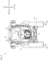
- Fig. 2 is a drawing from a direction of an arrow X in Fig. 1
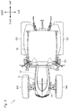
- Fig. 3 is a drawing from a direction of an arrow Y in Fig. 1
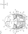
- Fig. 4 is a drawing from a direction of an arrow Z in Fig. 1 .
- longitudinal, lateral and vertical directions of the tractor 1 are shown.
- the tractor 1 includes mainly a chassis frame 11, an engine 12, a transmission 13, a front axle 14 and a rear axle 15.
- a bonnet 2 which protects the engine 12 from a rainstorm is provided.
- the chassis frame 11 constitutes a frame of the tractor 1.
- the engine 12 and the like explained below are attached to the chassis frame 11.
- the engine 12 exchanges heat energy obtained by combustion of fuel into kinetic energy. Namely, the engine 12 generates rotation power by making the fuel burn.
- driving state of the engine 12 is changed corresponding to the operation.
- the transmission 13 transmits the rotation power of the engine 12 to the front axle 14 and the rear axle 15.
- the rotation power of the engine 12 is inputted to the transmission 13 via a connection mechanism.
- the transmission 13 has a hydraulic-mechanical type stepless transmission (HMT or iHMT). When an operator operates a shift lever, operation state of the stepless transmission is changed corresponding to the operation.
- the front axle 14 transmits the rotation power of the engine 12 to front wheels 141.
- the rotation power of the engine 12 is inputted to the front axle 14 via the transmission 13.
- the front axle 14 is juxtaposed with a steering device. When an operator operates a steering wheel, the steering device changes a steering angle of the front wheels 141 corresponding to the operation.
- the rear axle 15 transmits the rotation power of the engine 12 to rear wheels 151.
- the rotation power of the engine 12 is inputted to the rear axle 15 via the transmission 13.
- a PTO output device is provided in the rear axle 15. The PTO output device inputs the rotation power to a led work machine.
- Fig. 5 shows the bonnet 2.
- Fig. 6 is a drawing from a direction of an arrow X in Fig. 5
- Fig. 7 is a drawing from a direction of an arrow Y in Fig. 5
- Fig. 8 is a drawing from a direction of an arrow Z in Fig. 5 .
- the longitudinal, lateral and vertical directions of the tractor 1 are shown.
- the bonnet 2 includes mainly an upper cover 21, a lower cover 22 and a front grill 23.
- a headlight device 3 illuminating the front at night is provided in the bonnet 2.
- the upper cover 21 is an exterior member covering an upper part of the engine 12.
- the upper cover 21 rises up from a front end point Ua thereof and is bent downward from a middle point Ub. Behind a vent hole 21h, the upper cover 21 curves gradually to a rear end point Uc. Furthermore, the upper cover 21 expands sideward from the front end point Ua and curves gradually so that side end points Uw are maximum width points.
- a character line C1 is formed from the front end point Ua to the middle point Ub
- character lines C2 are formed from the middle point Ub so as to expand sideward.
- the vent hole 21h is formed substantially wedge-like between the two character lines C2.
- the lower cover 22 is an exterior member covering a side part of the engine 12.
- the lower cover 22 expands sideward from a front end point La thereof and curves gradually so that side end points Lw are maximum width points. Furthermore, whereas an upper half part of the lower cover 22 is based on a curved surface expanded outward, a lower half part of the lower cover 22 is based on a curved surface depressed inward.
- character lines C3 which pass from the front end point La through the side end points Lw are formed. Vent holes 22ha are formed substantially lozenge-like above the character lines C3, and vent holes 22hb are formed substantially lozenge-like below the character lines C3.
- An upper front part of the lower cover 22 is formed corresponding to a shape of a high-beam lamp lens 43 discussed later. Since the shape of the high-beam lamp lens 43 hangs aslant, the shape of the upper front part of the lower cover 22 also hangs aslant.
- the front grill 23 is an exterior member covering a front part of the engine 12.
- the front grill 23 has a structure in which a metal mesh 232 is stuck on a support column 231.
- the support column 231 has beam parts 231L and 231R extended upward aslant from a center point Fa thereof and a pillar part 231P extended downward from the center point Fa.
- the beam parts 231L and 231R and the pillar part 231P become thin gradually as they separate from the center point Fa, and are connected to a grill frame 231G
- the metal mesh 232 covers three parts which includes a range surrounded by the beam parts 231L and 231R and the grill frame 231G, a range surrounded by the beam part 231L, the pillar part 231P and the grill frame 231G, and a range surrounded by the beam part 231R, the pillar part 231P and the grill frame 231G.
- both sides of an upper part of the front grill 23 are formed corresponding to the shape of the high-beam lamp lens 43 discussed later. Since the shape of the high-beam lamp lens 43 hangs aslant, the shapes of the sides of an upper part of the front grill 23 also hang aslant.
- a center mark 21M which is substantially I-like shaped is attached to an upper part of the upper cover 21 so as to cross the vent hole 21h.
- the center mark 21M is a sighting device for an operator to determine a traveling direction.
- a symbol mark 23M which is substantially Y-like shaped is attached to a front surface of the support column 231 so as to cover the beam parts 231L and 231R and the pillar part 231P.
- the symbol mark 23M is a design which symbolizes a supplier maker. Glossy plating is applied to the center mark 21M and the symbol mark 23M so as to make a strong impression on a third person.
- the headlight device 3 is explained in detail.
- Fig. 9 is shows the headlight device 3. In the drawing, the longitudinal, lateral and vertical directions of the tractor 1 are shown.
- the headlight device 3 includes mainly a pair of high-beam units 4L and 4R and a pair of low-beam units 5L and 5R.
- the high-beam units 4L and 4R and the low-beam units 5L and 5R are arranged respectively at upper and lower sides.
- an illumination part in a front surface of the bonnet 2 (a part which can emit light: see Figs. 12 and 15 ) has upper and lower two stages. Accordingly, the tractor 1 can make a strong impression on a third person so as to improve visibility.
- the high-beam unit 4L and the low-beam unit 5L are fixed to predetermined positions of the bonnet 2, they constitute a design having one light unit. Namely, the high-beam unit 4L and the low-beam unit 5L are combined so as to constitute the design in which they are connected integrally.
- the high-beam unit 4R and the low-beam unit 5R are fixed to predetermined positions of the bonnet 2, they constitute a design having one light unit. Namely, the high-beam unit 4R and the low-beam unit 5R are combined so as to constitute the design in which they are connected integrally.
- high-beam unit 4 the high-beam units 4L and 4R are explained in detail. Below explanation pays attention to the left high-beam unit 4L. For simplification, it is referred to as "high-beam unit 4".
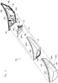
- Fig. 10 shows a structure of the high-beam unit 4.
- Fig. 11 shows a section of the high-beam unit 4.
- Fig. 12 shows a state in which the high-beam unit 4 illuminates the front.
- the high-beam unit 4 includes mainly a high-beam lamp 41, a high-beam lamp housing 42 and a high-beam lamp lens 43.
- the high-beam lamp 41 is a so-called halogen lamp.
- the halogen lamp emits light by using a halogen cycle.
- the halogen lamp has features of being bright and excelling in durability.
- the high-beam lamp housing 42 supports the high-beam lamp 41. Concretely, a stand 42S provided in a center part of the high-beam lamp housing 42 supports the high-beam lamp 41. In an outer edge part 42E of the high-beam lamp housing 42, a plurality of slits 42s are formed. On the slits 42s, lock pins 43R of the high-beam lamp lens 43 are hooked. In the outer edge part 42E of the high-beam lamp housing 42, brackets 421 and 422 are provided. The high-beam lamp housing 42 is fixed via the bracket 421 to the beam part 231L of the support column 231. The high-beam lamp housing 42 is fixed via the bracket 422 to the grill frame 231G of the support column 231.
- the high-beam lamp lens 43 covers the high-beam lamp 41.
- the high-beam lamp lens 43 is combined with the high-beam lamp housing 42 while the high-beam lamp 41 is housed in the high-beam lamp lens 43 so as to cover the high-beam lamp 41.
- the plurality of the lock pins 43R are formed in an outer edge part 43E of the high-beam lamp lens 43.
- the lock pins 43R are hooked on the slits 42s of the high-beam lamp housing 42.
- a projecting plate 43P is provided in the outer edge part 43E of the high-beam lamp lens 43.
- the high-beam lamp lens 43 is fixed while the projecting plate 43P is inserted into a recessed groove 42c of the high-beam lamp housing 42. Accordingly, dust and water are prevented from entering the inside.
- the high-beam lamp lens 43 is formed from the front surface to a side surface of the bonnet 2 (see arrows A and B of Fig. 9 ). Namely, the high-beam lamp lens 43 configures not only the front surface of the bonnet 2 but also the side surface of the bonnet 2 (see Figs. 5 , 6 and 7 ).
- an illumination part (a part which can emit light: see Fig. 12 ) which is extended laterally can be secured from the front surface to the side surface of the bonnet 2. Therefore, the tractor can make a strong impression on a third person so as to improve visibility.
- the high-beam lamp lens 43 is formed so as to be projected from the side surface of the bonnet 2 (see an arrow C of Fig. 9 ). Namely, the high-beam lamp lens 43 is not formed along the lower cover 22 but projected outward from the lower cover 22 (see Figs. 5 , 6 and 8 ).
- the tractor 1 having the headlight device 3 can illuminate by light emitted from an upper surface 43Us and a lower surface 43Ds of the high-beam lamp lens 43 (see parts signed by in Fig. 12 ). Therefore, the tractor 1 can make a strong impression on a third person so as to improve visibility.
- the high-beam unit 4 has a reflector 44 and an inner casing 45.
- the reflector 44 reflects light of the high-beam lamp 41.
- the reflector 44 surrounds the high-beam lamp 41 from a center to an outer edge part 44E thereof so as to reflect the light of the high-beam lamp 41.
- brackets 441 and 442 are provided in a rear surface of the reflector 44.
- the reflector 44 is fixed via the brackets 441 and 442 to the stand 42S of the high-beam lamp housing 42. Glossy plating is applied to a front surface 44Fs of the reflector 44. Accordingly, reflectance of the light is improved.
- the inner casing 45 covers the reflector 44. Concretely, the inner casing 45 is combined with the high-beam lamp housing 42 while the reflector 44 is housed in the inner casing 45 so as to cover the reflector 44. In a predetermined position of the inner casing 45, a substantially lozenge-like opening 45h is provided. The inner casing 45 is fixed so that the opening 45h is arranged inside the outer edge part 44E of the reflector 44. Glossy plating is applied to an outer surface 45Os of the inner casing 45. Accordingly, reflectance of the light is improved.
- the inner casing 45 is projected from the side surface of the bonnet 2 and formed along an inner surface 43Is of the high-beam lamp lens 43 (see the arrow C of Fig. 9 ). Namely, the inner casing 45 is projected outward from the lower cover 22 and is separated from the inner surface 43Is of the high-beam lamp lens 43 for a fixed interval. Accordingly, the light of the high-beam lamp 41 passes between the outer surface 45Os of the inner casing 45 and the inner surface 43Is of the high-beam lamp lens 43 and reaches an end of the high-beam lamp lens 43 (see an arrow L of Fig. 11 ).
- the high-beam lamp lens 43 constituting the side surface of the bonnet 2 can be made bright substantially uniformly (see Fig. 12 ). Therefore, the tractor 1 can make a strong impression on a third person so as to improve visibility.
- the inner casing 45 glossy plating is applied to the outer surface 45Os opposite to the high-beam lamp lens 43.
- chromium plating is applied. Accordingly, the light of the high-beam lamp 41 is hard to decline even when reflected by the outer surface 45Os of the inner casing 45 and reaches the end of the high-beam lamp lens 43 certainly. Accordingly, the whole high-beam lamp lens 43 is made bright.
- the high-beam lamp lens 43 constituting the side surface of the bonnet 2 can be made bright substantially uniformly further (see Fig. 12 ). Therefore, the tractor 1 can make a strong impression on a third person so as to improve visibility.
- low-beam unit 5L the low-beam units 5L and 5R are explained in detail. Below explanation pays attention to the left low-beam unit 5L. For simplification, it is referred to as "low-beam unit 5".
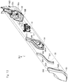
- Fig. 13 shows a structure of the low-beam unit 5.
- Fig. 14 shows a section of the low-beam unit 5.
- Fig. 15 shows a state in which the low-beam unit 5 illuminates the front.
- the low-beam unit 5 includes mainly a low-beam lamp 51, a low-beam lamp housing 52 and a low-beam lamp lens 53.
- the low-beam lamp 51 is a so-called halogen lamp.
- the halogen lamp emits light by using a halogen cycle.
- the halogen lamp has features of being bright and excelling in durability.
- the low-beam lamp 51 is housed in a projector unit 511.
- the projector unit 511 includes a reflector 512 and a lens 513.
- the lens 513 converges light of the low-beam lamp 51 so that the light with high directivity is emitted (the light hard to be diffused is emitted) from the lens 513. However, the lens 513 may be omitted.
- the low-beam lamp housing 52 supports the low-beam lamp 51.
- the projector unit 511 is fixed to a center part of the low-beam lamp housing 52 so as to support the low-beam lamp 51.
- a plurality of slits 52s are formed.
- lock pins 53R of the low-beam lamp lens 53 are hooked.
- brackets 521 and 522 are provided in the outer edge part 52E of the low-beam lamp housing 52.
- the low-beam lamp housing 52 is fixed via the bracket 521 to the grill frame 231G of the support column 231.
- the low-beam lamp housing 52 is fixed via the bracket 522 to the lower cover 22.
- the low-beam lamp lens 53 covers the low-beam lamp 51.
- the low-beam lamp lens 53 is combined with the low-beam lamp housing 52 while the projector unit 511 is housed in the low-beam lamp housing 52 so as to cover the low-beam lamp 51.
- the plurality of the lock pins 53R are formed in an outer edge part 53E of the low-beam lamp lens 53.
- the lock pins 53R are hooked on the slits 52s of the low-beam lamp housing 52.
- a projecting plate 53P is provided in the outer edge part 53E of the low-beam lamp lens 53.
- the low-beam lamp lens 53 is fixed while the projecting plate 53P is inserted into a recessed groove 52c of the low-beam lamp housing 52. Accordingly, dust and water are prevented from entering the inside.
- the low-beam lamp lens 53 is formed along the front grill 23 below the high-beam unit 4 (see an arrow D of Fig. 9 ). Namely, the low-beam lamp lens 53 is arranged below the high-beam lamp lens 43 while being engaged with the front grill 23 (see Figs. 5 and 6 ).
- an illumination part (a part which can emit light: see Fig. 15 ) which is extended longitudinally can be secured below the high-beam unit 4. Therefore, the tractor 1 can make a strong impression on a third person so as to improve visibility.
- the low-beam unit 5 has an inner plate 54 and an illumination lamp 55.
- the inner plate 54 covers the projector unit 511. Concretely, the inner plate 54 is combined with the low-beam lamp housing 52 while the projector unit 511 is housed in the low-beam lamp housing 52 so as to cover the projector unit 511. In a predetermined position of the inner plate 54, a circular opening 54h is provided. The inner plate 54 is fixed by engaging the lens 513 of the projector unit 511 with the opening 54h. Glossy plating is applied to a front surface 54Fs of the inner plate 54. Accordingly, reflectance of the light is improved.
- the illumination lamp 55 is a so-called LED light emitting diode.
- the LED light emitting diode emits light using an electroluminescence effect.
- the LED light emitting diode has features of being bright and excelling in durability.
- total 18 illumination lamps 55 are arranged along an outline of an inner end side of the low-beam lamp lens 53.
- the illumination lamps 55 are housed in a highlight unit 551.
- the highlight unit 551 includes a mount 552 and a cover 553. Since the cover 553 irregularly reflects light of the LED light emitting diodes, it seems that the cover 553 emits light uniformly (it seems that surface light emission is performed). However, the cover 553 may be omitted.
- the illumination lamp 55 highlights a zone along an outline of the low-beam lamp lens 53. Namely, the illumination lamp 55 illuminates a fixed range along the outline of the low-beam lamp lens 53 line-like.
- "Illuminates line-like" includes the case in which a curved surface of light is drawn by the surface light emission of the cover 553 and the case in which a curved surface of light is drawn by light emission of the illumination lamps 55 arranged continuously.
- the tractor 1 having the headlight device 3 the outline of the low-beam lamp lens 53 extended longitudinally can be emphasized (see Fig. 16 ). Therefore, the tractor 1 can make a strong impression on a third person so as to improve visibility.
- the illumination lamps 55 are turned on following turning on of a work lamp 161 and turned off following turning off of the work lamp 161.
- the work lamp 161 illuminates the front side and surrounding thereof of the bonnet 2 at the time of working.
- the work lamp 161 is arranged in the cabin 16 (see Figs. 1 , 2 and 3 ).
- the tractor 1 having the headlight device 3 appearance of the low-beam lamp lens 53 is changed corresponding to a driving state. Therefore, the tractor 1 can make a strong impression on a third person so as to improve visibility.
- the above is the explanation of the high-beam unit 4 and the low-beam unit 5 constituting the headlight device 3.
- the high-beam unit 4 and the low-beam unit 5 are connected to each other via a bracket 6 (see Fig. 17 ).
- the one high-beam unit 4 and the one low-beam unit 5 is configured integrally. Therefore, assembly processes of the tractor 1 can be simplified so as to improve production efficiency.
- the bracket 6 includes a first bracket 6a and a second bracket 6b.
- the first bracket 6a is projected upward from the low-beam lamp housing 52 and connected to the high-beam unit 4.
- the second bracket 6b is projected from the low-beam lamp housing 52 toward an inner end and connected to the high-beam unit 4.
- the first bracket 6a and the second bracket 6b are separated suitably so as to suppress shakiness.
- headlight devices 3S and 3T according to other embodiments are explained.
- Fig. 18 shows the headlight device 3S according to a second embodiment.
- Fig. 19 shows the headlight device 3T according to a third embodiment. In each of the drawings, the headlight device 3 according to the first embodiment is shown for comparison.
- the plurality of the illumination lamps 55 are arranged along the outline at the sides of inner and lower ends of the low-beam lamp lens 53. Accordingly, the illumination lamps 55 highlight a zone along the outline at the sides of inner and lower ends of the low-beam lamp lens 53. Namely, the illumination lamp 55 illuminates a fixed range along the outline at the sides of inner and lower ends of the low-beam lamp lens 53 line-like.
- the outline of the low-beam lamp lens 53 extended longitudinally can be emphasized.
- the design which emphasized the acute angle is obtained so as to bring a sharp impression. Therefore, the tractor 1 can make a strong impression on a third person so as to improve visibility.
- the plurality of the illumination lamps 55 are arranged so as to occupy an upper half of the low-beam lamp lens 53. Accordingly, the illumination lamps 55 highlight the upper half of the low-beam lamp lens 53. Namely, the illumination lamp 55 illuminates a range occupying the upper half of the low-beam lamp lens 53.
- the outline of the low-beam lamp lens 53 extended longitudinally can be emphasized.
- the design which emphasized width of the illumination part is obtained so as to bring a gorgeous impression. Therefore, the tractor 1 can make a strong impression on a third person so as to improve visibility.
- the present invention can be used for an art of a headlight device of a tractor. Description of Notations
Landscapes
- Engineering & Computer Science (AREA)
- Mechanical Engineering (AREA)
- General Engineering & Computer Science (AREA)
- Lighting Device Outwards From Vehicle And Optical Signal (AREA)
- Non-Portable Lighting Devices Or Systems Thereof (AREA)
Abstract
Description
- The present invention relates to a headlight device of a tractor.
- Conventionally, a tractor used in farmland is known (for example, see the Patent Literature 1). In a front part of the tractor, a bonnet is provided, and an engine is housed in the bonnet. In a front surface of the bonnet, a headlight device is arranged.
- The tractor has a characteristic that the bonnet is long and slender and a front surface area of the bonnet is small. In the tractor, a large front grill is provided in a front surface of the bonnet so as to take air in an inside of the bonnet. Accordingly, the headlight device of the tractor must be made small and cannot make a strong impression on a third person even when the headlight device is turned on. As a result, there is a problem that visibility by the third person is low. Accordingly, an art which can make a strong impression on a third person so as to improve visibility is desired.
- Patent Literature 1: the Japanese Patent Laid Open Gazette
2010-163036 - The purpose of the present invention is to provide an art which can make a strong impression on a third person so as to improve visibility.
- The first mode of the present invention is a headlight device of a tractor including a pair of high-beam units, and a pair of low-beam units, wherein the high-beam units and the low-beam units are arranged respectively at upper and lower sides.
- The second mode of the present invention is the headlight device according to the first mode wherein the high-beam unit includes a high-beam lamp, a high-beam lamp housing supporting the high-beam lamp, and a high-beam lamp lens covering the high-beam lamp, and the high-beam lamp lens is formed from a front surface to a side surface of a bonnet.
- The third mode of the present invention is the headlight device according to the second mode wherein the high-beam lamp lens is formed so as to be projected from the side surface of the bonnet.
- The fourth mode of the present invention is the headlight device according to the third mode wherein the high-beam unit includes a reflector reflecting light of the high-beam lamp, and an inner casing covering the reflector, and the inner casing is projected from the side surface of the bonnet and formed along an inner surface of the high-beam lamp lens.
- The fifth mode of the present invention is the headlight device according to the fourth mode wherein glossy plating is applied to an outer surface of the inner casing opposite to the high-beam lamp lens.
- The sixth mode of the present invention is the headlight device according to the first mode wherein the low-beam unit includes a low-beam lamp, a low-beam lamp housing supporting the low-beam lamp, and a low-beam lamp lens covering the low-beam lamp, and the low-beam lamp lens is formed along a front grill below the high-beam unit.
- The seventh mode of the present invention is the headlight device according to the sixth mode wherein the low-beam unit has one or more illumination lamps, and the illumination lamp highlights a zone along an outline of the low-beam lamp lens.
- The eighth mode of the present invention is the headlight device according to the seventh mode wherein the illumination lamps are turned on following turning on of a work lamp and turned off following turning off of the work lamp.
- The ninth mode of the present invention is the headlight device according to one of first to eighth modes wherein the high-beam unit and the low-beam unit are connected to each other via a bracket.
- The tenth mode of the present invention is a tractor including the headlight device according to one of first to ninth modes.
- The eleventh mode of the present invention is a tractor including the headlight device according to one of first to ninth modes, and a symbol mark arranged at a center of the headlight device.
- The present invention brings the following effects.
- According to the first mode of the present invention, the headlight device of the tractor according to the application includes the pair of the high-beam units, and the pair of the low-beam units, wherein the high-beam units and the low-beam units are arranged respectively at the upper and lower sides.
- Accordingly, in the tractor having the headlight device, an illumination part in the front surface of the bonnet (a part which can emit light) has upper and lower two stages. Accordingly, the tractor can make a strong impression on a third person so as to improve visibility.
- According to the second mode of the present invention, the high-beam unit includes the high-beam lamp, the high-beam lamp housing supporting the high-beam lamp, and the high-beam lamp lens covering the high-beam lamp. The high-beam lamp lens is formed from the front surface to the side surface of the bonnet. Accordingly, in the tractor having the headlight device, an illumination part which is extended laterally can be secured from the front surface to the side surface of the bonnet. Therefore, the tractor can make a strong impression on a third person so as to improve visibility.
- According to the third mode of the present invention, the high-beam lamp lens is formed so as to be projected from the side surface of the bonnet. Accordingly, the tractor having the headlight device can illuminate by light emitted from an upper surface and a lower surface of the high-beam lamp lens. Therefore, the tractor can make a strong impression on a third person so as to improve visibility.
- According to the fourth mode of the present invention, the high-beam unit includes the reflector reflecting light of the high-beam lamp, and the inner casing covering the reflector. The inner casing is projected from the side surface of the bonnet and formed along the inner surface of the high-beam lamp lens. Accordingly, in the tractor having the headlight device, the high-beam lamp lens constituting the side surface of the bonnet can be made bright substantially uniformly. Therefore, the tractor can make a strong impression on a third person so as to improve visibility.
- According to the fifth mode of the present invention, glossy plating is applied to the outer surface of the inner casing opposite to the high-beam lamp lens. Accordingly, in the tractor having the headlight device, the high-beam lamp lens constituting the side surface of the bonnet can be made bright substantially uniformly further. Therefore, the tractor can make a strong impression on a third person so as to improve visibility.
- According to the sixth mode of the present invention, the low-beam unit includes the low-beam lamp, the low-beam lamp housing supporting the low-beam lamp, and the low-beam lamp lens covering the low-beam lamp. The low-beam lamp lens is formed along the front grill below the high-beam unit. Accordingly, in the tractor having the headlight device, an illumination part (a part which can emit light) which is extended longitudinally can be secured below the high-beam unit. Therefore, the tractor can make a strong impression on a third person so as to improve visibility.
- According to the seventh mode of the present invention, the low-beam unit has one or more illumination lamps. The illumination lamp highlights the zone along the outline of the low-beam lamp lens. Accordingly, in the tractor having the headlight device, the outline of the low-beam lamp lens extended longitudinally can be emphasized. Therefore, the tractor can make a strong impression on a third person so as to improve visibility.
- According to the eighth mode of the present invention, the illumination lamps are turned on following turning on of the work lamp and turned off following turning off of the work lamp. Accordingly, in the tractor having the headlight device, appearance of the low-beam lamp lens is changed corresponding to a driving state. Therefore, the tractor can make a strong impression on a third person so as to improve visibility.
- According to the ninth mode of the present invention, the high-beam unit and the low-beam unit are connected to each other via a bracket. Accordingly, in the tractor having the headlight device, the one high-beam unit and the one low-beam unit is configured integrally. Therefore, assembly processes of the tractor can be simplified so as to improve production efficiency.
- According to the tenth mode of the present invention, the tractor has the headlight device according to one of first to ninth modes. Accordingly, the tractor can make a strong impression on a third person so as to improve visibility.
- According to the eleventh mode of the present invention, the tractor has the headlight device according to one of first to ninth modes, and the symbol mark arranged at the center of the headlight device. Accordingly, the tractor can make a strong impression on a third person so as to improve visibility.
-
- [
Fig. 1] Fig. 1 is a drawing of a tractor. - [
Fig. 2] Fig. 2 is a drawing from a direction of an arrow X inFig. 1 . - [
Fig. 3] Fig. 3 is a drawing from a direction of an arrow Y inFig. 1 . - [
Fig. 4] Fig. 4 is a drawing from a direction of an arrow Z inFig. 1 . - [
Fig. 5] Fig. 5 is a drawing of a bonnet. - [
Fig. 6] Fig. 6 is a drawing from a direction of an arrow X inFig. 5 . - [
Fig. 7] Fig. 7 is a drawing from a direction of an arrow Y inFig. 5 . - [
Fig. 8] Fig. 8 is a drawing from a direction of an arrow Z inFig. 5 . - [
Fig. 9] Fig. 9 is a drawing of a headlight device. - [
Fig. 10] Fig. 10 is a drawing of a structure of the high-beam unit. - [
Fig. 11] Fig. 11 is a drawing of a section of the high-beam unit. - [
Fig. 12] Fig. 12 is a drawing of a state in which the high-beam unit illuminates the front. - [
Fig. 13] Fig. 13 is a drawing of a structure of the low-beam unit. - [
Fig. 14] Fig. 14 is a drawing of a section of the low-beam unit. - [
Fig. 15] Fig. 15 is a drawing of a state in which the low-beam unit illuminates the front. - [
Fig. 16] Fig. 16 is a drawing of a state in which an illumination lamp is turned on. - [
Fig. 17] Fig. 17 is a drawing of a state in which the high-beam unit is connected to the low-beam unit. - [
Fig. 18] Fig. 18 is a drawing of a headlight device according to a second embodiment. - [
Fig. 19] Fig. 19 is a drawing of a headlight device according to a third embodiment. - Technical thought of the present invention can be used for all agricultural machine vehicles and construction machine vehicles.
- Firstly, a
tractor 1 is explained. -
Fig. 1 shows thetractor 1.Fig. 2 is a drawing from a direction of an arrow X inFig. 1 , andFig. 3 is a drawing from a direction of an arrow Y inFig. 1 . Furthermore,Fig. 4 is a drawing from a direction of an arrow Z inFig. 1 . In the drawings, longitudinal, lateral and vertical directions of thetractor 1 are shown. - The
tractor 1 includes mainly achassis frame 11, anengine 12, atransmission 13, afront axle 14 and arear axle 15. In thetractor 1, in addition to acabin 16 which protects an operator from a rainstorm, abonnet 2 which protects theengine 12 from a rainstorm is provided. - The
chassis frame 11 constitutes a frame of thetractor 1. Theengine 12 and the like explained below are attached to thechassis frame 11. - The
engine 12 exchanges heat energy obtained by combustion of fuel into kinetic energy. Namely, theengine 12 generates rotation power by making the fuel burn. When an operator operates an accelerator pedal, driving state of theengine 12 is changed corresponding to the operation. - The
transmission 13 transmits the rotation power of theengine 12 to thefront axle 14 and therear axle 15. The rotation power of theengine 12 is inputted to thetransmission 13 via a connection mechanism. Thetransmission 13 has a hydraulic-mechanical type stepless transmission (HMT or iHMT). When an operator operates a shift lever, operation state of the stepless transmission is changed corresponding to the operation. - The
front axle 14 transmits the rotation power of theengine 12 tofront wheels 141. The rotation power of theengine 12 is inputted to thefront axle 14 via thetransmission 13. Thefront axle 14 is juxtaposed with a steering device. When an operator operates a steering wheel, the steering device changes a steering angle of thefront wheels 141 corresponding to the operation. - The
rear axle 15 transmits the rotation power of theengine 12 torear wheels 151. The rotation power of theengine 12 is inputted to therear axle 15 via thetransmission 13. A PTO output device is provided in therear axle 15. The PTO output device inputs the rotation power to a led work machine. - Next, the
bonnet 2 is explained. -
Fig. 5 shows thebonnet 2.Fig. 6 is a drawing from a direction of an arrow X inFig. 5 , andFig. 7 is a drawing from a direction of an arrow Y inFig. 5 . Furthermore,Fig. 8 is a drawing from a direction of an arrow Z inFig. 5 . In the drawings, the longitudinal, lateral and vertical directions of thetractor 1 are shown. - The
bonnet 2 includes mainly anupper cover 21, alower cover 22 and afront grill 23. Aheadlight device 3 illuminating the front at night is provided in thebonnet 2. - The
upper cover 21 is an exterior member covering an upper part of theengine 12. Theupper cover 21 rises up from a front end point Ua thereof and is bent downward from a middle point Ub. Behind avent hole 21h, theupper cover 21 curves gradually to a rear end point Uc. Furthermore, theupper cover 21 expands sideward from the front end point Ua and curves gradually so that side end points Uw are maximum width points. In theupper cover 21, a character line C1 is formed from the front end point Ua to the middle point Ub, and character lines C2 are formed from the middle point Ub so as to expand sideward. Thevent hole 21h is formed substantially wedge-like between the two character lines C2. - The
lower cover 22 is an exterior member covering a side part of theengine 12. Thelower cover 22 expands sideward from a front end point La thereof and curves gradually so that side end points Lw are maximum width points. Furthermore, whereas an upper half part of thelower cover 22 is based on a curved surface expanded outward, a lower half part of thelower cover 22 is based on a curved surface depressed inward. In thelower cover 22, character lines C3 which pass from the front end point La through the side end points Lw are formed. Vent holes 22ha are formed substantially lozenge-like above the character lines C3, and vent holes 22hb are formed substantially lozenge-like below the character lines C3. An upper front part of thelower cover 22 is formed corresponding to a shape of a high-beam lamp lens 43 discussed later. Since the shape of the high-beam lamp lens 43 hangs aslant, the shape of the upper front part of thelower cover 22 also hangs aslant. - The
front grill 23 is an exterior member covering a front part of theengine 12. Thefront grill 23 has a structure in which ametal mesh 232 is stuck on asupport column 231. Thesupport column 231 hasbeam parts pillar part 231P extended downward from the center point Fa. Thebeam parts pillar part 231P become thin gradually as they separate from the center point Fa, and are connected to agrill frame 231G Themetal mesh 232 covers three parts which includes a range surrounded by thebeam parts grill frame 231G, a range surrounded by thebeam part 231L, thepillar part 231P and thegrill frame 231G, and a range surrounded by thebeam part 231R, thepillar part 231P and thegrill frame 231G. In addition, both sides of an upper part of thefront grill 23 are formed corresponding to the shape of the high-beam lamp lens 43 discussed later. Since the shape of the high-beam lamp lens 43 hangs aslant, the shapes of the sides of an upper part of thefront grill 23 also hang aslant. - Furthermore, the
bonnet 2 has below features. Acenter mark 21M which is substantially I-like shaped is attached to an upper part of theupper cover 21 so as to cross thevent hole 21h. Thecenter mark 21M is a sighting device for an operator to determine a traveling direction. Asymbol mark 23M which is substantially Y-like shaped is attached to a front surface of thesupport column 231 so as to cover thebeam parts pillar part 231P. Thesymbol mark 23M is a design which symbolizes a supplier maker. Glossy plating is applied to thecenter mark 21M and thesymbol mark 23M so as to make a strong impression on a third person. - Next, the
headlight device 3 is explained in detail. -
Fig. 9 is shows theheadlight device 3. In the drawing, the longitudinal, lateral and vertical directions of thetractor 1 are shown. - The
headlight device 3 includes mainly a pair of high-beam units beam units beam units beam units - According to the configuration, in the
tractor 1 having theheadlight device 3, an illumination part in a front surface of the bonnet 2 (a part which can emit light: seeFigs. 12 and15 ) has upper and lower two stages. Accordingly, thetractor 1 can make a strong impression on a third person so as to improve visibility. - When the high-
beam unit 4L and the low-beam unit 5L are fixed to predetermined positions of thebonnet 2, they constitute a design having one light unit. Namely, the high-beam unit 4L and the low-beam unit 5L are combined so as to constitute the design in which they are connected integrally. - Similarly, when the high-
beam unit 4R and the low-beam unit 5R are fixed to predetermined positions of thebonnet 2, they constitute a design having one light unit. Namely, the high-beam unit 4R and the low-beam unit 5R are combined so as to constitute the design in which they are connected integrally. - Next, the high-
beam units beam unit 4L. For simplification, it is referred to as "high-beam unit 4". -
Fig. 10 shows a structure of the high-beam unit 4.Fig. 11 shows a section of the high-beam unit 4.Fig. 12 shows a state in which the high-beam unit 4 illuminates the front. - The high-
beam unit 4 includes mainly a high-beam lamp 41, a high-beam lamp housing 42 and a high-beam lamp lens 43. - The high-
beam lamp 41 is a so-called halogen lamp. The halogen lamp emits light by using a halogen cycle. The halogen lamp has features of being bright and excelling in durability. - The high-
beam lamp housing 42 supports the high-beam lamp 41. Concretely, astand 42S provided in a center part of the high-beam lamp housing 42 supports the high-beam lamp 41. In anouter edge part 42E of the high-beam lamp housing 42, a plurality ofslits 42s are formed. On theslits 42s, lock pins 43R of the high-beam lamp lens 43 are hooked. In theouter edge part 42E of the high-beam lamp housing 42,brackets beam lamp housing 42 is fixed via thebracket 421 to thebeam part 231L of thesupport column 231. The high-beam lamp housing 42 is fixed via thebracket 422 to thegrill frame 231G of thesupport column 231. - The high-
beam lamp lens 43 covers the high-beam lamp 41. Concretely, the high-beam lamp lens 43 is combined with the high-beam lamp housing 42 while the high-beam lamp 41 is housed in the high-beam lamp lens 43 so as to cover the high-beam lamp 41. In anouter edge part 43E of the high-beam lamp lens 43, the plurality of the lock pins 43R are formed. The lock pins 43R are hooked on theslits 42s of the high-beam lamp housing 42. In theouter edge part 43E of the high-beam lamp lens 43, a projectingplate 43P is provided. The high-beam lamp lens 43 is fixed while the projectingplate 43P is inserted into a recessedgroove 42c of the high-beam lamp housing 42. Accordingly, dust and water are prevented from entering the inside. - Characteristics of the high-
beam unit 4 are explained below. - The high-
beam lamp lens 43 is formed from the front surface to a side surface of the bonnet 2 (see arrows A and B ofFig. 9 ). Namely, the high-beam lamp lens 43 configures not only the front surface of thebonnet 2 but also the side surface of the bonnet 2 (seeFigs. 5 ,6 and7 ). - Accordingly, in the
tractor 1 having theheadlight device 3, an illumination part (a part which can emit light: seeFig. 12 ) which is extended laterally can be secured from the front surface to the side surface of thebonnet 2. Therefore, the tractor can make a strong impression on a third person so as to improve visibility. - Furthermore, the high-
beam lamp lens 43 is formed so as to be projected from the side surface of the bonnet 2 (see an arrow C ofFig. 9 ). Namely, the high-beam lamp lens 43 is not formed along thelower cover 22 but projected outward from the lower cover 22 (seeFigs. 5 ,6 and8 ). - Accordingly, the
tractor 1 having theheadlight device 3 can illuminate by light emitted from an upper surface 43Us and a lower surface 43Ds of the high-beam lamp lens 43 (see parts signed byin
Fig. 12 ). Therefore, thetractor 1 can make a strong impression on a third person so as to improve visibility. - Additionally, the high-
beam unit 4 has areflector 44 and aninner casing 45. - The
reflector 44 reflects light of the high-beam lamp 41. Concretely, thereflector 44 surrounds the high-beam lamp 41 from a center to anouter edge part 44E thereof so as to reflect the light of the high-beam lamp 41. In a rear surface of thereflector 44,brackets reflector 44 is fixed via thebrackets stand 42S of the high-beam lamp housing 42. Glossy plating is applied to a front surface 44Fs of thereflector 44. Accordingly, reflectance of the light is improved. - The
inner casing 45 covers thereflector 44. Concretely, theinner casing 45 is combined with the high-beam lamp housing 42 while thereflector 44 is housed in theinner casing 45 so as to cover thereflector 44. In a predetermined position of theinner casing 45, a substantially lozenge-like opening 45h is provided. Theinner casing 45 is fixed so that theopening 45h is arranged inside theouter edge part 44E of thereflector 44. Glossy plating is applied to an outer surface 45Os of theinner casing 45. Accordingly, reflectance of the light is improved. - Other characteristics of the high-
beam unit 4 are explained below. - The
inner casing 45 is projected from the side surface of thebonnet 2 and formed along an inner surface 43Is of the high-beam lamp lens 43 (see the arrow C ofFig. 9 ). Namely, theinner casing 45 is projected outward from thelower cover 22 and is separated from the inner surface 43Is of the high-beam lamp lens 43 for a fixed interval. Accordingly, the light of the high-beam lamp 41 passes between the outer surface 45Os of theinner casing 45 and the inner surface 43Is of the high-beam lamp lens 43 and reaches an end of the high-beam lamp lens 43 (see an arrow L ofFig. 11 ). - Accordingly, in the
tractor 1 having theheadlight device 3, the high-beam lamp lens 43 constituting the side surface of thebonnet 2 can be made bright substantially uniformly (seeFig. 12 ). Therefore, thetractor 1 can make a strong impression on a third person so as to improve visibility. - Furthermore, as mentioned above, in the
inner casing 45, glossy plating is applied to the outer surface 45Os opposite to the high-beam lamp lens 43. Concretely, chromium plating is applied. Accordingly, the light of the high-beam lamp 41 is hard to decline even when reflected by the outer surface 45Os of theinner casing 45 and reaches the end of the high-beam lamp lens 43 certainly. Accordingly, the whole high-beam lamp lens 43 is made bright. - Accordingly, in the
tractor 1 having theheadlight device 3, the high-beam lamp lens 43 constituting the side surface of thebonnet 2 can be made bright substantially uniformly further (seeFig. 12 ). Therefore, thetractor 1 can make a strong impression on a third person so as to improve visibility. - Next, the low-
beam units beam unit 5L. For simplification, it is referred to as "low-beam unit 5". -
Fig. 13 shows a structure of the low-beam unit 5.Fig. 14 shows a section of the low-beam unit 5.Fig. 15 shows a state in which the low-beam unit 5 illuminates the front. - The low-
beam unit 5 includes mainly a low-beam lamp 51, a low-beam lamp housing 52 and a low-beam lamp lens 53. - The low-
beam lamp 51 is a so-called halogen lamp. The halogen lamp emits light by using a halogen cycle. The halogen lamp has features of being bright and excelling in durability. The low-beam lamp 51 is housed in aprojector unit 511. Theprojector unit 511 includes areflector 512 and alens 513. Thelens 513 converges light of the low-beam lamp 51 so that the light with high directivity is emitted (the light hard to be diffused is emitted) from thelens 513. However, thelens 513 may be omitted. - The low-
beam lamp housing 52 supports the low-beam lamp 51. Concretely, theprojector unit 511 is fixed to a center part of the low-beam lamp housing 52 so as to support the low-beam lamp 51. In anouter edge part 52E of the low-beam lamp housing 52, a plurality ofslits 52s are formed. On theslits 52s, lock pins 53R of the low-beam lamp lens 53 are hooked. In theouter edge part 52E of the low-beam lamp housing 52,brackets beam lamp housing 52 is fixed via thebracket 521 to thegrill frame 231G of thesupport column 231. The low-beam lamp housing 52 is fixed via thebracket 522 to thelower cover 22. - The low-
beam lamp lens 53 covers the low-beam lamp 51. Concretely, the low-beam lamp lens 53 is combined with the low-beam lamp housing 52 while theprojector unit 511 is housed in the low-beam lamp housing 52 so as to cover the low-beam lamp 51. In anouter edge part 53E of the low-beam lamp lens 53, the plurality of the lock pins 53R are formed. The lock pins 53R are hooked on theslits 52s of the low-beam lamp housing 52. In theouter edge part 53E of the low-beam lamp lens 53, a projectingplate 53P is provided. The low-beam lamp lens 53 is fixed while the projectingplate 53P is inserted into a recessedgroove 52c of the low-beam lamp housing 52. Accordingly, dust and water are prevented from entering the inside. - Characteristics of the low-
beam unit 5 are explained below. - The low-
beam lamp lens 53 is formed along thefront grill 23 below the high-beam unit 4 (see an arrow D ofFig. 9 ). Namely, the low-beam lamp lens 53 is arranged below the high-beam lamp lens 43 while being engaged with the front grill 23 (seeFigs. 5 and6 ). - Accordingly, in the
tractor 1 having theheadlight device 3, an illumination part (a part which can emit light: seeFig. 15 ) which is extended longitudinally can be secured below the high-beam unit 4. Therefore, thetractor 1 can make a strong impression on a third person so as to improve visibility. - Additionally, the low-
beam unit 5 has aninner plate 54 and anillumination lamp 55. - The
inner plate 54 covers theprojector unit 511. Concretely, theinner plate 54 is combined with the low-beam lamp housing 52 while theprojector unit 511 is housed in the low-beam lamp housing 52 so as to cover theprojector unit 511. In a predetermined position of theinner plate 54, acircular opening 54h is provided. Theinner plate 54 is fixed by engaging thelens 513 of theprojector unit 511 with theopening 54h. Glossy plating is applied to a front surface 54Fs of theinner plate 54. Accordingly, reflectance of the light is improved. - The
illumination lamp 55 is a so-called LED light emitting diode. The LED light emitting diode emits light using an electroluminescence effect. The LED light emitting diode has features of being bright and excelling in durability. In the low-beam unit 5, total 18illumination lamps 55 are arranged along an outline of an inner end side of the low-beam lamp lens 53. Theillumination lamps 55 are housed in ahighlight unit 551. Thehighlight unit 551 includes amount 552 and acover 553. Since thecover 553 irregularly reflects light of the LED light emitting diodes, it seems that thecover 553 emits light uniformly (it seems that surface light emission is performed). However, thecover 553 may be omitted. - Other characteristics of the low-
beam unit 5 are explained below. - The
illumination lamp 55 highlights a zone along an outline of the low-beam lamp lens 53. Namely, theillumination lamp 55 illuminates a fixed range along the outline of the low-beam lamp lens 53 line-like. "Illuminates line-like" includes the case in which a curved surface of light is drawn by the surface light emission of thecover 553 and the case in which a curved surface of light is drawn by light emission of theillumination lamps 55 arranged continuously. - Accordingly, in the
tractor 1 having theheadlight device 3, the outline of the low-beam lamp lens 53 extended longitudinally can be emphasized (seeFig. 16 ). Therefore, thetractor 1 can make a strong impression on a third person so as to improve visibility. - Furthermore, the
illumination lamps 55 are turned on following turning on of awork lamp 161 and turned off following turning off of thework lamp 161. Herein, thework lamp 161 illuminates the front side and surrounding thereof of thebonnet 2 at the time of working. In thetractor 1, thework lamp 161 is arranged in the cabin 16 (seeFigs. 1 ,2 and3 ). - Accordingly, in the
tractor 1 having theheadlight device 3, appearance of the low-beam lamp lens 53 is changed corresponding to a driving state. Therefore, thetractor 1 can make a strong impression on a third person so as to improve visibility. - The above is the explanation of the high-
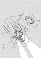
beam unit 4 and the low-beam unit 5 constituting theheadlight device 3. The high-beam unit 4 and the low-beam unit 5 are connected to each other via a bracket 6 (seeFig. 17 ). - Accordingly, in the
tractor 1 having theheadlight device 3, the one high-beam unit 4 and the one low-beam unit 5 is configured integrally. Therefore, assembly processes of thetractor 1 can be simplified so as to improve production efficiency. - In the
headlight device 3, thebracket 6 includes afirst bracket 6a and asecond bracket 6b. Thefirst bracket 6a is projected upward from the low-beam lamp housing 52 and connected to the high-beam unit 4. Thesecond bracket 6b is projected from the low-beam lamp housing 52 toward an inner end and connected to the high-beam unit 4. Thefirst bracket 6a and thesecond bracket 6b are separated suitably so as to suppress shakiness. - Next,
headlight devices -
Fig. 18 shows theheadlight device 3S according to a second embodiment.Fig. 19 shows theheadlight device 3T according to a third embodiment. In each of the drawings, theheadlight device 3 according to the first embodiment is shown for comparison. - In the low-
beam unit 5 of theheadlight device 3S, the plurality of theillumination lamps 55 are arranged along the outline at the sides of inner and lower ends of the low-beam lamp lens 53. Accordingly, theillumination lamps 55 highlight a zone along the outline at the sides of inner and lower ends of the low-beam lamp lens 53. Namely, theillumination lamp 55 illuminates a fixed range along the outline at the sides of inner and lower ends of the low-beam lamp lens 53 line-like. - Accordingly, in the
tractor 1 having theheadlight device 3S, the outline of the low-beam lamp lens 53 extended longitudinally can be emphasized. The design which emphasized the acute angle is obtained so as to bring a sharp impression. Therefore, thetractor 1 can make a strong impression on a third person so as to improve visibility. - In the low-
beam unit 5 of theheadlight device 3T, the plurality of theillumination lamps 55 are arranged so as to occupy an upper half of the low-beam lamp lens 53. Accordingly, theillumination lamps 55 highlight the upper half of the low-beam lamp lens 53. Namely, theillumination lamp 55 illuminates a range occupying the upper half of the low-beam lamp lens 53. - Accordingly, in the
tractor 1 having theheadlight device 3T, the outline of the low-beam lamp lens 53 extended longitudinally can be emphasized. The design which emphasized width of the illumination part is obtained so as to bring a gorgeous impression. Therefore, thetractor 1 can make a strong impression on a third person so as to improve visibility. - The present invention can be used for an art of a headlight device of a tractor. Description of Notations
-
- 1
- tractor
- 6
- bracket
- 11
- chassis frame
- 12
- engine
- 13
- transmission
- 14
- front axle
- 15
- rear axle
- 16
- cabin
- 2
- bonnet
- 21
- upper cover
- 22
- lower cover
- 23
- front grill
- 3
- headlight device
- 4
- high-beam unit
- 41
- high-beam lamp
- 42
- high-beam lamp housing
- 43
- high-beam lamp lens
- 44
- reflector
- 45
- inner casing
- 5
- low-beam unit
- 51
- low-beam lamp
- 52
- low-beam lamp housing
- 53
- low-beam lamp lens
- 54
- inner plate
- 55
- illumination lamp
Claims (11)
- A headlight device of a tractor comprising:a pair of high-beam units; anda pair of low-beam units,characterized in thatthe high-beam units and the low-beam units are arranged respectively at upper and lower sides.
- The headlight device of the tractor according to claim 1,
wherein the high-beam unit comprises:a high-beam lamp;a high-beam lamp housing supporting the high-beam lamp; anda high-beam lamp lens covering the high-beam lamp, andwherein the high-beam lamp lens is formed from a front surface to a side surface of a bonnet. - The headlight device of the tractor according to claim 2, wherein the high-beam lamp lens is formed so as to be projected from the side surface of the bonnet.
- The headlight device of the tractor according to claim 3,
wherein the high-beam unit comprises:a reflector reflecting light of the high-beam lamp; andan inner casing covering the reflector, andwherein the inner casing is projected from the side surface of the bonnet and formed along an inner surface of the high-beam lamp lens. - The headlight device of the tractor according to claim 4, wherein glossy plating is applied to an outer surface of the inner casing opposite to the high-beam lamp lens.
- The headlight device of the tractor according to claim 1,
wherein the low-beam unit comprises:a low-beam lamp;a low-beam lamp housing supporting the low-beam lamp; anda low-beam lamp lens covering the low-beam lamp, andwherein the low-beam lamp lens is formed along a front grill below the high-beam unit. - The headlight device of the tractor according to claim 6,
wherein the low-beam unit has one or more illumination lamps, and
wherein the illumination lamp highlights a zone along an outline of the low-beam lamp lens. - The headlight device of the tractor according to claim 7, wherein the illumination lamps are turned on following turning on of a work lamp and turned off following turning off of the work lamp.
- The headlight device of the tractor according to one of claims 1 to 8, wherein the high-beam unit and the low-beam unit are connected to each other via a bracket.
- A tractor comprising the headlight device according to one of claims 1 to 9.
- A tractor comprising:the headlight device according to one of claims 1 to 9; anda symbol mark arranged at a center of the headlight device.
Applications Claiming Priority (2)
| Application Number | Priority Date | Filing Date | Title |
|---|---|---|---|
| JP2014113555A JP6297418B2 (en) | 2014-05-30 | 2014-05-30 | Tractor headlight device |
| PCT/JP2015/065177 WO2015182637A1 (en) | 2014-05-30 | 2015-05-27 | Tractor headlight device |
Publications (3)
| Publication Number | Publication Date |
|---|---|
| EP3162632A1 true EP3162632A1 (en) | 2017-05-03 |
| EP3162632A4 EP3162632A4 (en) | 2018-01-24 |
| EP3162632B1 EP3162632B1 (en) | 2021-04-21 |
Family
ID=54698961
Family Applications (1)
| Application Number | Title | Priority Date | Filing Date |
|---|---|---|---|
| EP15799385.8A Active EP3162632B1 (en) | 2014-05-30 | 2015-05-27 | Tractor headlight device |
Country Status (6)
| Country | Link |
|---|---|
| US (1) | US9925913B2 (en) |
| EP (1) | EP3162632B1 (en) |
| JP (1) | JP6297418B2 (en) |
| KR (1) | KR101881686B1 (en) |
| CN (1) | CN106458082B (en) |
| WO (1) | WO2015182637A1 (en) |
Cited By (2)
| Publication number | Priority date | Publication date | Assignee | Title |
|---|---|---|---|---|
| EP4043282A1 (en) * | 2021-02-16 | 2022-08-17 | odelo GmbH | Vehicle part and vehicle having the same |
| EP4707073A1 (en) * | 2024-09-06 | 2026-03-11 | Yanmar Holdings Co., Ltd. | Work vehicle |
Families Citing this family (6)
| Publication number | Priority date | Publication date | Assignee | Title |
|---|---|---|---|---|
| CN105584566B (en) * | 2014-10-24 | 2021-09-24 | 雅马哈发动机株式会社 | Scooter type vehicle |
| CN108189749A (en) * | 2018-02-11 | 2018-06-22 | 道依茨法尔机械有限公司 | Wheeled tractor hood lamp combination |
| SE542144C2 (en) * | 2018-05-28 | 2020-03-03 | Husqvarna Ab | Headlight assembly for a mower |
| USD976968S1 (en) * | 2019-03-22 | 2023-01-31 | Deere & Company | Work vehicle hood |
| USD1040387S1 (en) * | 2022-06-08 | 2024-08-27 | Changzhou T&D International Trading Co., Ltd. | Vehicle headlight |
| US12227122B2 (en) * | 2023-06-21 | 2025-02-18 | Brinkley RV LLC | Front cap with integrated illumination |
Family Cites Families (22)
| Publication number | Priority date | Publication date | Assignee | Title |
|---|---|---|---|---|
| FR557511A (en) * | 1922-10-17 | 1923-08-10 | Improvements in automotive headlamp installations | |
| GB1326601A (en) * | 1970-01-23 | 1973-08-15 | Lucas Industries Ltd | Headlamp assemblies |
| JPS57178949A (en) * | 1981-04-30 | 1982-11-04 | Nissan Motor Co Ltd | Monitoring device of car head lamp |
| US4758932A (en) * | 1987-07-13 | 1988-07-19 | J. I. Case Company | Dual front headlight assembly |
| US6401851B1 (en) * | 2000-09-14 | 2002-06-11 | Deere & Company | Hood assembly |
| JP4248758B2 (en) * | 2001-04-02 | 2009-04-02 | 日産自動車株式会社 | Lamp device for vehicle |
| JP3942384B2 (en) | 2001-06-22 | 2007-07-11 | 株式会社クボタ | Headlamp for work equipment |
| DE20309082U1 (en) * | 2003-06-12 | 2003-10-23 | Automotive Lighting Reutlingen | Headlight unit for a vehicle with several headlight subunits |
| US7033053B2 (en) * | 2004-02-27 | 2006-04-25 | Guide Corporation | High/low beam adjuster bracket assembly |
| JP4568167B2 (en) * | 2005-05-13 | 2010-10-27 | 株式会社クボタ | Tractor lighting structure |
| JP4563912B2 (en) * | 2005-10-05 | 2010-10-20 | 本田技研工業株式会社 | Vehicle headlamp structure |
| JP2007137236A (en) * | 2005-11-17 | 2007-06-07 | Kubota Corp | Tractor lighting device |
| KR20090063573A (en) * | 2007-12-14 | 2009-06-18 | 현대자동차주식회사 | LED Headlamp Aiming Device |
| JP5435965B2 (en) | 2009-01-15 | 2014-03-05 | ヤンマー株式会社 | Tractor |
| JP5031058B2 (en) * | 2009-07-23 | 2012-09-19 | 日産自動車株式会社 | Air flow control device around side mirror of vehicle |
| US8444306B2 (en) * | 2010-12-20 | 2013-05-21 | Caterpillar Inc. | Vocational truck headlight assembly |
| GB201104158D0 (en) * | 2011-03-11 | 2011-04-27 | Agco Int Gmbh | Engine hood arrangement |
| JP2013043623A (en) * | 2011-08-26 | 2013-03-04 | Stanley Electric Co Ltd | Lighting control device of vehicle headlamp, and vehicle headlamp system |
| JP5659105B2 (en) * | 2011-08-29 | 2015-01-28 | 株式会社クボタ | Support structure for headlamp cover |
| JP6035901B2 (en) * | 2012-06-28 | 2016-11-30 | 市光工業株式会社 | Vehicle lighting |
| JP6148558B2 (en) * | 2013-07-24 | 2017-06-14 | ヤンマー株式会社 | Tractor |
| CN203580752U (en) * | 2013-11-20 | 2014-05-07 | 徐州工程学院 | Large tractor |
-
2014
- 2014-05-30 JP JP2014113555A patent/JP6297418B2/en active Active
-
2015
- 2015-05-27 EP EP15799385.8A patent/EP3162632B1/en active Active
- 2015-05-27 US US15/315,109 patent/US9925913B2/en active Active
- 2015-05-27 KR KR1020167034735A patent/KR101881686B1/en active Active
- 2015-05-27 WO PCT/JP2015/065177 patent/WO2015182637A1/en not_active Ceased
- 2015-05-27 CN CN201580028962.0A patent/CN106458082B/en active Active
Cited By (2)
| Publication number | Priority date | Publication date | Assignee | Title |
|---|---|---|---|---|
| EP4043282A1 (en) * | 2021-02-16 | 2022-08-17 | odelo GmbH | Vehicle part and vehicle having the same |
| EP4707073A1 (en) * | 2024-09-06 | 2026-03-11 | Yanmar Holdings Co., Ltd. | Work vehicle |
Also Published As
| Publication number | Publication date |
|---|---|
| JP2015227120A (en) | 2015-12-17 |
| KR101881686B1 (en) | 2018-07-24 |
| KR20170007397A (en) | 2017-01-18 |
| US20170190278A1 (en) | 2017-07-06 |
| EP3162632A4 (en) | 2018-01-24 |
| JP6297418B2 (en) | 2018-03-20 |
| WO2015182637A1 (en) | 2015-12-03 |
| US9925913B2 (en) | 2018-03-27 |
| CN106458082B (en) | 2019-07-16 |
| CN106458082A (en) | 2017-02-22 |
| EP3162632B1 (en) | 2021-04-21 |
Similar Documents
| Publication | Publication Date | Title |
|---|---|---|
| EP3162632B1 (en) | Tractor headlight device | |
| JP6792427B2 (en) | Vehicle lighting | |
| JP6194540B2 (en) | Indirect light emitting front grille | |
| JP5551979B2 (en) | Vehicle lamp arrangement structure | |
| US9248776B2 (en) | Vehicular light unit with multiple light sources | |
| TW200724432A (en) | A lighting system for vehicle | |
| CN102313222A (en) | Vehicular lamp | |
| JP2013178904A (en) | Headlight structure of motorcycle | |
| CN107107814B (en) | Tractor | |
| JP6495712B2 (en) | Headlight | |
| AU2018361984B2 (en) | Headlight for a vehicle | |
| JP2016110845A (en) | Vehicle lighting appliance | |
| EP3000656A1 (en) | Headlight structure for vehicle | |
| JP2014159257A (en) | Lamp | |
| JP2013122872A (en) | Illumination lamp fitting for vehicle | |
| CN107429898B (en) | headlamp | |
| CN100572898C (en) | Two-wheeled rear combination lamp structure | |
| CN203010497U (en) | Integrated Radial Lamp Lens | |
| JP6885982B2 (en) | Headlight structure of saddle-riding vehicle | |
| JP2013149503A (en) | Vehicular lamp | |
| KR101865943B1 (en) | Lamp for automobile | |
| JP2015167096A (en) | Vehicle lighting | |
| CN100462622C (en) | vehicle lights | |
| JP5032907B2 (en) | Vehicle lighting | |
| JP2015185324A (en) | transplanter |
Legal Events
| Date | Code | Title | Description |
|---|---|---|---|
| STAA | Information on the status of an ep patent application or granted ep patent |
Free format text: STATUS: THE INTERNATIONAL PUBLICATION HAS BEEN MADE |
|
| PUAI | Public reference made under article 153(3) epc to a published international application that has entered the european phase |
Free format text: ORIGINAL CODE: 0009012 |
|
| STAA | Information on the status of an ep patent application or granted ep patent |
Free format text: STATUS: REQUEST FOR EXAMINATION WAS MADE |
|
| 17P | Request for examination filed |
Effective date: 20170102 |
|
| AK | Designated contracting states |
Kind code of ref document: A1 Designated state(s): AL AT BE BG CH CY CZ DE DK EE ES FI FR GB GR HR HU IE IS IT LI LT LU LV MC MK MT NL NO PL PT RO RS SE SI SK SM TR |
|
| AX | Request for extension of the european patent |
Extension state: BA ME |
|
| DAV | Request for validation of the european patent (deleted) | ||
| DAX | Request for extension of the european patent (deleted) | ||
| A4 | Supplementary search report drawn up and despatched |
Effective date: 20171221 |
|
| RIC1 | Information provided on ipc code assigned before grant |
Ipc: B60Q 1/04 20060101AFI20171215BHEP Ipc: F21S 8/10 00000000ALI20171215BHEP Ipc: B60Q 1/00 20060101ALI20171215BHEP Ipc: B62D 25/10 20060101ALI20171215BHEP Ipc: F21W 101/10 00000000ALI20171215BHEP Ipc: F21Y 101/00 20160101ALI20171215BHEP |
|
| STAA | Information on the status of an ep patent application or granted ep patent |
Free format text: STATUS: EXAMINATION IS IN PROGRESS |
|
| 17Q | First examination report despatched |
Effective date: 20180731 |
|
| RIC1 | Information provided on ipc code assigned before grant |
Ipc: B60Q 1/00 20060101ALI20171215BHEP Ipc: F21Y 101/00 20160101ALI20171215BHEP Ipc: B60Q 1/04 20060101AFI20171215BHEP Ipc: B62D 25/10 20060101ALI20171215BHEP Ipc: F21W 101/10 20060101ALI20171215BHEP Ipc: F21S 8/10 20060101ALI20171215BHEP |
|
| RAP1 | Party data changed (applicant data changed or rights of an application transferred) |
Owner name: YANMAR POWER TECHNOLOGY CO., LTD. |
|
| RIC1 | Information provided on ipc code assigned before grant |
Ipc: F21Y 101/00 20160101ALI20200831BHEP Ipc: B60Q 1/00 20060101ALI20200831BHEP Ipc: F21S 43/00 20180101ALI20200831BHEP Ipc: B60Q 1/04 20060101AFI20200831BHEP Ipc: B62D 25/10 20060101ALI20200831BHEP |
|
| GRAP | Despatch of communication of intention to grant a patent |
Free format text: ORIGINAL CODE: EPIDOSNIGR1 |
|
| STAA | Information on the status of an ep patent application or granted ep patent |
Free format text: STATUS: GRANT OF PATENT IS INTENDED |
|
| INTG | Intention to grant announced |
Effective date: 20201013 |
|
| GRAJ | Information related to disapproval of communication of intention to grant by the applicant or resumption of examination proceedings by the epo deleted |
Free format text: ORIGINAL CODE: EPIDOSDIGR1 |
|
| STAA | Information on the status of an ep patent application or granted ep patent |
Free format text: STATUS: EXAMINATION IS IN PROGRESS |
|
| INTC | Intention to grant announced (deleted) | ||
| GRAP | Despatch of communication of intention to grant a patent |
Free format text: ORIGINAL CODE: EPIDOSNIGR1 |
|
| STAA | Information on the status of an ep patent application or granted ep patent |
Free format text: STATUS: GRANT OF PATENT IS INTENDED |
|
| INTG | Intention to grant announced |
Effective date: 20210208 |
|
| RIN1 | Information on inventor provided before grant (corrected) |
Inventor name: KUDOU JUNKO Inventor name: KUROKAWA YOSHIAKI |
|
| GRAS | Grant fee paid |
Free format text: ORIGINAL CODE: EPIDOSNIGR3 |
|
| GRAA | (expected) grant |
Free format text: ORIGINAL CODE: 0009210 |
|
| STAA | Information on the status of an ep patent application or granted ep patent |
Free format text: STATUS: THE PATENT HAS BEEN GRANTED |
|
| AK | Designated contracting states |
Kind code of ref document: B1 Designated state(s): AL AT BE BG CH CY CZ DE DK EE ES FI FR GB GR HR HU IE IS IT LI LT LU LV MC MK MT NL NO PL PT RO RS SE SI SK SM TR |
|
| REG | Reference to a national code |
Ref country code: GB Ref legal event code: FG4D |
|
| REG | Reference to a national code |
Ref country code: CH Ref legal event code: EP |
|
| REG | Reference to a national code |
Ref country code: DE Ref legal event code: R096 Ref document number: 602015068420 Country of ref document: DE Ref country code: IE Ref legal event code: FG4D |
|
| REG | Reference to a national code |
Ref country code: AT Ref legal event code: REF Ref document number: 1384306 Country of ref document: AT Kind code of ref document: T Effective date: 20210515 |
|
| REG | Reference to a national code |
Ref country code: LT Ref legal event code: MG9D |
|
| REG | Reference to a national code |
Ref country code: AT Ref legal event code: MK05 Ref document number: 1384306 Country of ref document: AT Kind code of ref document: T Effective date: 20210421 |
|
| REG | Reference to a national code |
Ref country code: NL Ref legal event code: MP Effective date: 20210421 |
|
| PG25 | Lapsed in a contracting state [announced via postgrant information from national office to epo] |
Ref country code: AT Free format text: LAPSE BECAUSE OF FAILURE TO SUBMIT A TRANSLATION OF THE DESCRIPTION OR TO PAY THE FEE WITHIN THE PRESCRIBED TIME-LIMIT Effective date: 20210421 Ref country code: BG Free format text: LAPSE BECAUSE OF FAILURE TO SUBMIT A TRANSLATION OF THE DESCRIPTION OR TO PAY THE FEE WITHIN THE PRESCRIBED TIME-LIMIT Effective date: 20210721 Ref country code: HR Free format text: LAPSE BECAUSE OF FAILURE TO SUBMIT A TRANSLATION OF THE DESCRIPTION OR TO PAY THE FEE WITHIN THE PRESCRIBED TIME-LIMIT Effective date: 20210421 Ref country code: NL Free format text: LAPSE BECAUSE OF FAILURE TO SUBMIT A TRANSLATION OF THE DESCRIPTION OR TO PAY THE FEE WITHIN THE PRESCRIBED TIME-LIMIT Effective date: 20210421 Ref country code: LT Free format text: LAPSE BECAUSE OF FAILURE TO SUBMIT A TRANSLATION OF THE DESCRIPTION OR TO PAY THE FEE WITHIN THE PRESCRIBED TIME-LIMIT Effective date: 20210421 Ref country code: FI Free format text: LAPSE BECAUSE OF FAILURE TO SUBMIT A TRANSLATION OF THE DESCRIPTION OR TO PAY THE FEE WITHIN THE PRESCRIBED TIME-LIMIT Effective date: 20210421 |
|
| PG25 | Lapsed in a contracting state [announced via postgrant information from national office to epo] |
Ref country code: LV Free format text: LAPSE BECAUSE OF FAILURE TO SUBMIT A TRANSLATION OF THE DESCRIPTION OR TO PAY THE FEE WITHIN THE PRESCRIBED TIME-LIMIT Effective date: 20210421 Ref country code: IS Free format text: LAPSE BECAUSE OF FAILURE TO SUBMIT A TRANSLATION OF THE DESCRIPTION OR TO PAY THE FEE WITHIN THE PRESCRIBED TIME-LIMIT Effective date: 20210821 Ref country code: GR Free format text: LAPSE BECAUSE OF FAILURE TO SUBMIT A TRANSLATION OF THE DESCRIPTION OR TO PAY THE FEE WITHIN THE PRESCRIBED TIME-LIMIT Effective date: 20210722 Ref country code: NO Free format text: LAPSE BECAUSE OF FAILURE TO SUBMIT A TRANSLATION OF THE DESCRIPTION OR TO PAY THE FEE WITHIN THE PRESCRIBED TIME-LIMIT Effective date: 20210721 Ref country code: PT Free format text: LAPSE BECAUSE OF FAILURE TO SUBMIT A TRANSLATION OF THE DESCRIPTION OR TO PAY THE FEE WITHIN THE PRESCRIBED TIME-LIMIT Effective date: 20210823 Ref country code: PL Free format text: LAPSE BECAUSE OF FAILURE TO SUBMIT A TRANSLATION OF THE DESCRIPTION OR TO PAY THE FEE WITHIN THE PRESCRIBED TIME-LIMIT Effective date: 20210421 Ref country code: ES Free format text: LAPSE BECAUSE OF FAILURE TO SUBMIT A TRANSLATION OF THE DESCRIPTION OR TO PAY THE FEE WITHIN THE PRESCRIBED TIME-LIMIT Effective date: 20210421 Ref country code: RS Free format text: LAPSE BECAUSE OF FAILURE TO SUBMIT A TRANSLATION OF THE DESCRIPTION OR TO PAY THE FEE WITHIN THE PRESCRIBED TIME-LIMIT Effective date: 20210421 Ref country code: SE Free format text: LAPSE BECAUSE OF FAILURE TO SUBMIT A TRANSLATION OF THE DESCRIPTION OR TO PAY THE FEE WITHIN THE PRESCRIBED TIME-LIMIT Effective date: 20210421 |
|
| REG | Reference to a national code |
Ref country code: CH Ref legal event code: PL |
|
| REG | Reference to a national code |
Ref country code: DE Ref legal event code: R097 Ref document number: 602015068420 Country of ref document: DE |
|
| PG25 | Lapsed in a contracting state [announced via postgrant information from national office to epo] |
Ref country code: CZ Free format text: LAPSE BECAUSE OF FAILURE TO SUBMIT A TRANSLATION OF THE DESCRIPTION OR TO PAY THE FEE WITHIN THE PRESCRIBED TIME-LIMIT Effective date: 20210421 Ref country code: EE Free format text: LAPSE BECAUSE OF FAILURE TO SUBMIT A TRANSLATION OF THE DESCRIPTION OR TO PAY THE FEE WITHIN THE PRESCRIBED TIME-LIMIT Effective date: 20210421 Ref country code: DK Free format text: LAPSE BECAUSE OF FAILURE TO SUBMIT A TRANSLATION OF THE DESCRIPTION OR TO PAY THE FEE WITHIN THE PRESCRIBED TIME-LIMIT Effective date: 20210421 Ref country code: SK Free format text: LAPSE BECAUSE OF FAILURE TO SUBMIT A TRANSLATION OF THE DESCRIPTION OR TO PAY THE FEE WITHIN THE PRESCRIBED TIME-LIMIT Effective date: 20210421 Ref country code: SM Free format text: LAPSE BECAUSE OF FAILURE TO SUBMIT A TRANSLATION OF THE DESCRIPTION OR TO PAY THE FEE WITHIN THE PRESCRIBED TIME-LIMIT Effective date: 20210421 Ref country code: RO Free format text: LAPSE BECAUSE OF FAILURE TO SUBMIT A TRANSLATION OF THE DESCRIPTION OR TO PAY THE FEE WITHIN THE PRESCRIBED TIME-LIMIT Effective date: 20210421 Ref country code: CH Free format text: LAPSE BECAUSE OF NON-PAYMENT OF DUE FEES Effective date: 20210531 Ref country code: LI Free format text: LAPSE BECAUSE OF NON-PAYMENT OF DUE FEES Effective date: 20210531 Ref country code: LU Free format text: LAPSE BECAUSE OF NON-PAYMENT OF DUE FEES Effective date: 20210527 Ref country code: MC Free format text: LAPSE BECAUSE OF FAILURE TO SUBMIT A TRANSLATION OF THE DESCRIPTION OR TO PAY THE FEE WITHIN THE PRESCRIBED TIME-LIMIT Effective date: 20210421 |
|
| REG | Reference to a national code |
Ref country code: BE Ref legal event code: MM Effective date: 20210531 |
|
| PLBE | No opposition filed within time limit |
Free format text: ORIGINAL CODE: 0009261 |
|
| STAA | Information on the status of an ep patent application or granted ep patent |
Free format text: STATUS: NO OPPOSITION FILED WITHIN TIME LIMIT |
|
| GBPC | Gb: european patent ceased through non-payment of renewal fee |
Effective date: 20210721 |
|
| 26N | No opposition filed |
Effective date: 20220124 |
|
| PG25 | Lapsed in a contracting state [announced via postgrant information from national office to epo] |
Ref country code: IE Free format text: LAPSE BECAUSE OF NON-PAYMENT OF DUE FEES Effective date: 20210527 Ref country code: GB Free format text: LAPSE BECAUSE OF NON-PAYMENT OF DUE FEES Effective date: 20210721 |
|
| PG25 | Lapsed in a contracting state [announced via postgrant information from national office to epo] |
Ref country code: IS Free format text: LAPSE BECAUSE OF FAILURE TO SUBMIT A TRANSLATION OF THE DESCRIPTION OR TO PAY THE FEE WITHIN THE PRESCRIBED TIME-LIMIT Effective date: 20210821 Ref country code: AL Free format text: LAPSE BECAUSE OF FAILURE TO SUBMIT A TRANSLATION OF THE DESCRIPTION OR TO PAY THE FEE WITHIN THE PRESCRIBED TIME-LIMIT Effective date: 20210421 |
|
| PG25 | Lapsed in a contracting state [announced via postgrant information from national office to epo] |
Ref country code: IT Free format text: LAPSE BECAUSE OF FAILURE TO SUBMIT A TRANSLATION OF THE DESCRIPTION OR TO PAY THE FEE WITHIN THE PRESCRIBED TIME-LIMIT Effective date: 20210421 Ref country code: BE Free format text: LAPSE BECAUSE OF NON-PAYMENT OF DUE FEES Effective date: 20210531 |
|
| PG25 | Lapsed in a contracting state [announced via postgrant information from national office to epo] |
Ref country code: HU Free format text: LAPSE BECAUSE OF FAILURE TO SUBMIT A TRANSLATION OF THE DESCRIPTION OR TO PAY THE FEE WITHIN THE PRESCRIBED TIME-LIMIT; INVALID AB INITIO Effective date: 20150527 |
|
| PG25 | Lapsed in a contracting state [announced via postgrant information from national office to epo] |
Ref country code: CY Free format text: LAPSE BECAUSE OF FAILURE TO SUBMIT A TRANSLATION OF THE DESCRIPTION OR TO PAY THE FEE WITHIN THE PRESCRIBED TIME-LIMIT Effective date: 20210421 |
|
| PG25 | Lapsed in a contracting state [announced via postgrant information from national office to epo] |
Ref country code: MK Free format text: LAPSE BECAUSE OF FAILURE TO SUBMIT A TRANSLATION OF THE DESCRIPTION OR TO PAY THE FEE WITHIN THE PRESCRIBED TIME-LIMIT Effective date: 20210421 |
|
| PG25 | Lapsed in a contracting state [announced via postgrant information from national office to epo] |
Ref country code: TR Free format text: LAPSE BECAUSE OF FAILURE TO SUBMIT A TRANSLATION OF THE DESCRIPTION OR TO PAY THE FEE WITHIN THE PRESCRIBED TIME-LIMIT Effective date: 20210421 |
|
| PG25 | Lapsed in a contracting state [announced via postgrant information from national office to epo] |
Ref country code: MT Free format text: LAPSE BECAUSE OF FAILURE TO SUBMIT A TRANSLATION OF THE DESCRIPTION OR TO PAY THE FEE WITHIN THE PRESCRIBED TIME-LIMIT Effective date: 20210421 |
|
| PGFP | Annual fee paid to national office [announced via postgrant information from national office to epo] |
Ref country code: DE Payment date: 20250521 Year of fee payment: 11 |
|
| PGFP | Annual fee paid to national office [announced via postgrant information from national office to epo] |
Ref country code: FR Payment date: 20250528 Year of fee payment: 11 |