EP3162603A1 - Open roof construction for a vehicle - Google Patents
Open roof construction for a vehicle Download PDFInfo
- Publication number
- EP3162603A1 EP3162603A1 EP15192122.8A EP15192122A EP3162603A1 EP 3162603 A1 EP3162603 A1 EP 3162603A1 EP 15192122 A EP15192122 A EP 15192122A EP 3162603 A1 EP3162603 A1 EP 3162603A1
- Authority
- EP
- European Patent Office
- Prior art keywords
- screen
- guide
- transverse
- roof construction
- transverse guide
- Prior art date
- Legal status (The legal status is an assumption and is not a legal conclusion. Google has not performed a legal analysis and makes no representation as to the accuracy of the status listed.)
- Granted
Links
Images



Classifications
-
- B—PERFORMING OPERATIONS; TRANSPORTING
- B60—VEHICLES IN GENERAL
- B60J—WINDOWS, WINDSCREENS, NON-FIXED ROOFS, DOORS, OR SIMILAR DEVICES FOR VEHICLES; REMOVABLE EXTERNAL PROTECTIVE COVERINGS SPECIALLY ADAPTED FOR VEHICLES
- B60J7/00—Non-fixed roofs; Roofs with movable panels, e.g. rotary sunroofs
- B60J7/0007—Non-fixed roofs; Roofs with movable panels, e.g. rotary sunroofs moveable head-liners, screens, curtains or blinds for ceilings
- B60J7/0015—Non-fixed roofs; Roofs with movable panels, e.g. rotary sunroofs moveable head-liners, screens, curtains or blinds for ceilings roller blind
Definitions
- the invention relates to an open roof construction according to the preamble of claims 1 and 9.
- An open roof construction of this type is for example known from US 6,546,990 .
- the transverse guide therein is shaped like a convex arch (tunnel) and the screen is guided by the upper surface of the transverse guide.
- the open roof construction according to the invention includes the features of claim 1. Due to this special contour of the transverse guide, the screen may be adapted to the contour of the vehicle roof and may be shaped such that maximum headroom for the vehicle's occupants is created This concave shape is made possible by the transverse guide that guides both the upper and lower surfaces of the screen at least in the concave section of the transverse guide.
- the open roof construction according to the invention includes the features of claim 9.
- This at least one longitudinal guide is able to guide the screen along its length between the transverse guide and the beam, thereby enabling guidance of the screen close to the panel of the open roof construction and preventing sagging of the screen between the transverse guide and beam.
- the beam has a shape in transverse direction which is substantially similar to that of the transverse guide, so that the shape of the screen can remain the same along its length.
- At least the transverse guide has a central concave section and a convex section on either side thereof. This maximizes the head room of the occupants of the vehicle which are generally sitting between the centre and the sides of the vehicle.
- the central concave section disguises any sagging in the middle of the screen.
- the transverse guide may guide the upper and lower surfaces of the screen substantially along the complete width of the screen, or may guide the upper surface of the screen only in the concave section. This would be sufficient as the tension and gravity will make the screen contact the transverse guide in the convex sections.
- the transverse guide may have upper and lower guide parts that overlap at least partly when viewed from above in order to guide the screen in an efficient manner.
- the lateral side edges of the screen are preferably guided by lateral guides extending in longitudinal direction in order to properly stretch the screen in transverse direction.
- the longitudinal guide may guide the screen at the bottom of the concave portion of the screen in order to properly maintain the concave shape of the screen between the transverse guide and the beam.
- one longitudinal guide extends in the middle of the roof opening at a level higher than the lateral guides which guide the lateral side edges of the screen and beam.in order to maximize the headspace of the occupants and/or prevent sagging.
- two longitudinal guides extend next to but at a higher level than the lateral guides. This can maximize the headroom for the occupants of the vehicle.
- the transverse guide guides at least a part of both the upper and lower surfaces of the screen in order to urge the screen into a partly convex and partly concave shape
- the at least one longitudinal guide is positioned at the bottom of the concave shape and includes a guide groove
- the screen comprising one or more guide feet adapted to engage the guide groove on the one hand and adapted to lie flat against the screen when it is wound on the other hand.
- the screen is urged into a wavelike shape which is guided along the complete length of the screen.
- the central longitudinal guide also guides a drive cable extending between the beam and a drive motor. Thus, only one drive cable is necessary for driving the beam of the sunshade screen.
- Fig. 1 shows a small portion of a fixed roof 1 of a vehicle, such as a passenger car or utility vehicle. It comprises a roof opening 2 for the purpose of accommodating an open roof construction.
- the fixed roof 1 may be part of the vehicle or part of the open roof construction replacing the normal roof of the vehicle.
- the open roof construction comprises a closure element 3 in the form of a rigid panel, which is at least partly transparent by being made from glass or plastic, and which closes the roof opening 2 in its closed position ( Fig. 1 ) and which can be opened from said closed position. It may for example be opened by moving the rear side of the panel 3 upwardly and sliding the panel 3 rearwardly over the fixed roof 1 or any other part present behind the roof opening 1, for example a second transparent panel which may be fixed.
- the open roof construction comprises a stationary part or frame 4 which is fixed to the fixed roof 1, here represented by a fixing screw 5.
- the frame 4 comprises longitudinal guiderails laterally of the passage opening 8 to movably guide the operating mechanism for the panel 3.
- a drive member in particular an electric motor, is used to drive the operating mechanism through drive cables which are guided in drive cable guides 6 shown in Fig. 1 .
- the drawing further shows a portion of a sunshade or rollo assembly 7 which is movably arranged below the panel 3 and which is adapted to close and open a passage opening 8 in the frame situated below the roof opening 2.
- Figs. 1A , 2 , 4 and 5 show a first embodiment of the sunshade assembly. It includes a winding mechanism (only a winding tube 9 is shown) and a screen 10 which is stretched in a non-linear shape in transverse direction during use.
- the screen 10 is generally of a textile material which may be fully or partially of an elastic nature such that it can be stretched elastically in longitudinal and/or lateral direction. It has an upper and lower surface, lateral side edges, and a leading edge having a beam 11 attached to it.
- the ends of the beam 11 and side edges of the screen 10 are generally guided in lateral guides 12 which extend in longitudinal direction of the open roof construction near the edges of the passage opening 8 (and in extension thereof) and substantially below the lateral edges of the roof opening 2.
- An attached edge of the screen 10 (opposite to the beam 11) is attached to the winding tube 9 of the winding mechanism, which is rotatable about a transverse axis of rotation 13 for winding and unwinding said screen 9 between an extended position screening the passage opening 8 and thereby roof opening 2 and a retracted position releasing said passage and roof openings.
- a transverse guide 14 for the screen 9 extends in transverse direction and is attached with its ends to the stationary part 4 of the open roof construction, in this case to the lateral guides 12.
- the transverse guide 13 is positioned between the beam 11 and the winding tube 9, when the screen 10 is unwound from or wound on the winding tube 9.In the latter case the beam 11 is positioned close to the transverse guide 14.
- the transverse guide 13 is positioned close to the rear edge of the passage opening 8, and may either be just behind (so invisible to the occupants), at or in front of this rear edge (visible to the occupants).
- the transverse guide 14 is at least partly curved in transverse direction to form the screen 10 from a linear shape on the winding tube 9 into a non-linear shape between the transverse guide 14 and the beam 11.
- the transverse guide 14 has a central concave section 14' and a convex section 14" on either side thereof.
- the beam 11 has a shape in transverse direction which is similar to that of the transverse guide 14.
- the convex sections 14" are bow or arch shaped and extend from the lateral guides upwardly, so that more headroom is created for the occupants of the vehicle, which are normally positioned between the centre and the sides of the interior of the vehicle.
- the centre of the concave section 14' may for example be at the same level again as the lateral guides 12, but other variations are conceivable.
- Fig. 2 shows that in this embodiment the transverse guide 14 is also shaped such that at least the rear edge of the transverse guide 14 has a non-linear shape when viewed from above. In this case the front and rear edges of the transverse guide are parallel to each other.
- Figs. 4 and 5 show that at the bottom of concave section 14' and at the top of convex section 14" both the height and the longitudinal position of the transverse guide is different.
- the extent of the rear edge of the transverse guide 14 is such that, for all points that are located on a line perpendicular to and between the lateral edges of the screen 10, a distance from each of said points via the transverse guide 14 and via a surface of the winding tube 9 to a line on the surface of the winding tube 9 that extends parallel to the axis of rotation 13 is the same for all of said points. Due to this equal distance the screen 10 is stretched equally over its whole width, so that there is no risk of formation of wrinkles in the screen 10 due to uneven stretching.
- This principle is set out in US patent 6,546,990 the contents of which are incorporated herein by reference thereto.
- the screen 10 is here led to the upper side of the winding tube 9 to create the different angles of the screen 10 between the rear edge of the transverse guide 14 and the winding tube 9.
- the transverse guide is such that it guides the upper and lower surfaces of screen 10 along the complete width thereof.
- the transverse guide 14 has a longitudinal slot 14A extending along substantially the complete transverse length of the transverse guide 14, such that the screen 10 can be guided through the slot 14A.
- the upper and lower walls of the slot 14A in the transverse guide 14 are parallel to each other so that they both engage the upper and lower surfaces of the screen 10 along substantially its complete width.
- Fig. 3 shows a variation of the transverse guide 14 having a lower guide part 15A similar to a lower portion below slot 14A in the transverse guide of Fig. 2 , and having an upper guide part 15B which only extends through the central portion of the concave section 14' of the transverse guide 14.
- This upper guide part 15B urges the central portion of the screen 10 into the concave section 14' in order to follow the curve of the lower guide part 15A of the transverse guide 14.
- the upper guide part can be attached to the stationary part 4 of the open roof construction at a position behind the winding tube (cf. Fig. 11 ).
- the lower guide part 15A may be attached to the lower side of the lateral guides 12 for example.
- Fig. 6 shows a further embodiment in which both the transverse guide 14 and the beam 11 having a roof shape including two inclined straight lateral sections and a central curved section connecting the lateral sections.
- Fig. 10 illustrates that the cross section of transverse guide 14 may be slightly concavely curved and inclined backwardly and downwardly to smoothly guide the screen between the transverse guide 14 and the winding tube 9.
- a longitudinal guide 16 having a slightly convexly curved cross section of its upper guide surface.
- the longitudinal guide 16 will be attached to the stationary part 4 at the front of the passage opening 8 and to transverse guide 14 and may form one part therewith, as is shown in Fig. 7 , but could as well be a separate part.
- Fig. 8 shows that a cover 17 may be provided below longitudinal guide 16, which may have just a visual function or carry accessories, such as lights, compartments, switches or the like.
- Fig. 9 shows a further embodiment including two longitudinal guides 16 positioned close to the lateral guides 12 but at a higher level so that the screen 10 is guided from the lateral guides 12 in upward direction and then in a straight line to the opposite longitudinal guide 16.
- the cross section of the longitudinal guides 16 is convexly curved so that the screen 10 is smoothly guided over its upper surface.
- the longitudinal guides 16 may include a substantially vertical side cover 16' on their sides facing the interior of the vehicle so as to hide the operating mechanism for the panel 3.
- the transverse guide 14 will have a shape similar to that of the screen 10 in Fig. 9 .
- the beam in Fig. 9 is shaped differently at the ends. The edges of screen 10 will be attached then to slides supporting beam 11 (not shown).
- the guidance of the lateral side edges of the screen 10 in all embodiments will generally be such that these side edges will be held substantially in position when lateral forces are exerted on the screen 10.
- the side edges may for example be provided with strips held in a groove of the lateral guides 12 as is known in the prior art, for example from US patent 9,090,147 , the contents of which are incorporated herein by reference thereto.
- Fig. 11 shows still another embodiment of the sunshade assembly.
- the transverse guide 14 is constructed similar to that of Fig. 3
- beam 11 is similar to that of Fig. 1A .
- This embodiment also includes a longitudinal guide 16 which is positioned in the centre between lateral guides 12 and below the bottom of concave section 14' of transverse guide. Due to this position, the beam 11 will not guide or support the screen 10 in the position between the beam 11 and transverse guide 14 without further measures, as the tension in the screen will pull it away from the longitudinal guide 16. For this reason, longitudinal 16 comprises a longitudinal guiderail 18 in which guide feet 19 on the lower surface of screen 10 engage.
- the beam 11 comprises a slide shoe 20 fitting into the guiderail 18 to guide beam 11 also in its centre.
- a cover 17 is again present in this embodiment.
- Fig. 14 - 17 includes a drive cable 21 attached to the central slide shoe 20 of beam 10 instead of the slide shoes 24 at the lateral ends of beam 11.
- a drive motor 22 may be attached to the stationary part 4 at a position below or behind winding tube 9, although a position on the opposite edge of the passage opening 8 is conceivable.
- the guiderail 18 includes a cable channel 23 so that it can guide the drive cable in both pushing and pulling situations to close and open the screen 10.
- Fig. 16 and 17 show the slide shoes 24 attached to the ends of beam 11. These are special slide shoes counteracting a tilting movement of beam 11 when eccentric forces are exerted thereon, here through a set of rotatable rollers.
- the invention provides an open roof construction having a sunshade assembly of which the screen is guided and supported in an effective manner so that sagging is prevented and additional headroom for the vehicle's occupants is provided.
Landscapes
- Engineering & Computer Science (AREA)
- Mechanical Engineering (AREA)
- Operating, Guiding And Securing Of Roll- Type Closing Members (AREA)
Abstract
Description
- The invention relates to an open roof construction according to the preamble of
claims - An open roof construction of this type is for example known from
US 6,546,990 . The transverse guide therein is shaped like a convex arch (tunnel) and the screen is guided by the upper surface of the transverse guide. - It is an object of the invention to further improve the guidance and shape of the screen.
- According to a first aspect, the open roof construction according to the invention includes the features of
claim 1. Due to this special contour of the transverse guide, the screen may be adapted to the contour of the vehicle roof and may be shaped such that maximum headroom for the vehicle's occupants is created This concave shape is made possible by the transverse guide that guides both the upper and lower surfaces of the screen at least in the concave section of the transverse guide. - According to a second aspect of the invention the open roof construction according to the invention includes the features of
claim 9. This at least one longitudinal guide is able to guide the screen along its length between the transverse guide and the beam, thereby enabling guidance of the screen close to the panel of the open roof construction and preventing sagging of the screen between the transverse guide and beam. - Preferably, the beam has a shape in transverse direction which is substantially similar to that of the transverse guide, so that the shape of the screen can remain the same along its length.
- In one embodiment, at least the transverse guide has a central concave section and a convex section on either side thereof. This maximizes the head room of the occupants of the vehicle which are generally sitting between the centre and the sides of the vehicle. The central concave section disguises any sagging in the middle of the screen.
- The transverse guide may guide the upper and lower surfaces of the screen substantially along the complete width of the screen, or may guide the upper surface of the screen only in the concave section. This would be sufficient as the tension and gravity will make the screen contact the transverse guide in the convex sections.
- The transverse guide may have upper and lower guide parts that overlap at least partly when viewed from above in order to guide the screen in an efficient manner.
- The lateral side edges of the screen are preferably guided by lateral guides extending in longitudinal direction in order to properly stretch the screen in transverse direction.
- The longitudinal guide may guide the screen at the bottom of the concave portion of the screen in order to properly maintain the concave shape of the screen between the transverse guide and the beam.
- In another embodiment, one longitudinal guide extends in the middle of the roof opening at a level higher than the lateral guides which guide the lateral side edges of the screen and beam.in order to maximize the headspace of the occupants and/or prevent sagging.
- In yet another embodiment, two longitudinal guides extend next to but at a higher level than the lateral guides. This can maximize the headroom for the occupants of the vehicle.
- In a particular embodiment, the transverse guide guides at least a part of both the upper and lower surfaces of the screen in order to urge the screen into a partly convex and partly concave shape, while the at least one longitudinal guide is positioned at the bottom of the concave shape and includes a guide groove, the screen comprising one or more guide feet adapted to engage the guide groove on the one hand and adapted to lie flat against the screen when it is wound on the other hand.
- In this manner, the screen is urged into a wavelike shape which is guided along the complete length of the screen.
- It is possible that the central longitudinal guide also guides a drive cable extending between the beam and a drive motor. Thus, only one drive cable is necessary for driving the beam of the sunshade screen.
- Further features and advantages of the invention follow from the below description with reference to the drawings showing, in a schematic and simplified form, embodiments of the invention by way of example.
-
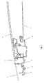
Fig. 1 is a longitudinal sectional view of a front portion of an open roof construction for a vehicle as built into a vehicle roof. -
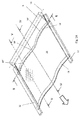
Fig. 1A is a perspective view of a first embodiment of the sunshade assembly for use in the open roof construction ofFig. 1 . -
Fig. 2 is an enlarged sectional view according to the line II-II inFig. 1A . -
Fig. 3 is a sectional view corresponding to that ofFig. 2 , but showing a different embodiment of the sunshade assembly. -
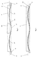
Figs. 4 and 5 are enlarged sectional views along the lines IV-IV and V-V inFig. 2 , respectively. -
Fig. 6 is a view corresponding to that ofFig. 2 but showing a further embodiment of the sunshade assembly. -
Fig. 7 is a perspective view of the transverse and longitudinal guide. -
Fig. 8 is an enlarged sectional view along the line VIII-VIII inFig. 6 . -
Fig. 9 is a view corresponding to that ofFig. 8 , but showing a different embodiment of the sunshade assembly. -
Fig. 10 is a sectional view along the line X-X inFig. 6 . -
Fig. 11 is a perspective view corresponding to that ofFig. 2 , but showing another embodiment of the sunshade assembly. -
Figs. 12 and 13 are enlarged sectional views along the lines XII-XII and XIII-XIII inFig. 11 , respectively. -
Fig. 14 is a perspective view corresponding to that ofFig. 2 , but showing yet another embodiment of the sunshade assembly. -
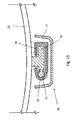
Figs. 15 and16 are enlarged sectional views along the lines XV-XV and XVI-XVI inFig. 14 , respectively. -
Fig. 17 is a bottom view of the subject ofFig. 16 . -
Fig. 1 shows a small portion of afixed roof 1 of a vehicle, such as a passenger car or utility vehicle. It comprises aroof opening 2 for the purpose of accommodating an open roof construction. Thefixed roof 1 may be part of the vehicle or part of the open roof construction replacing the normal roof of the vehicle. In this embodiment, the open roof construction comprises aclosure element 3 in the form of a rigid panel, which is at least partly transparent by being made from glass or plastic, and which closes the roof opening 2 in its closed position (Fig. 1 ) and which can be opened from said closed position. It may for example be opened by moving the rear side of thepanel 3 upwardly and sliding thepanel 3 rearwardly over thefixed roof 1 or any other part present behind theroof opening 1, for example a second transparent panel which may be fixed. - The open roof construction comprises a stationary part or
frame 4 which is fixed to thefixed roof 1, here represented by afixing screw 5. Theframe 4 comprises longitudinal guiderails laterally of the passage opening 8 to movably guide the operating mechanism for thepanel 3. A drive member, in particular an electric motor, is used to drive the operating mechanism through drive cables which are guided indrive cable guides 6 shown inFig. 1 . - The drawing further shows a portion of a sunshade or
rollo assembly 7 which is movably arranged below thepanel 3 and which is adapted to close and open a passage opening 8 in the frame situated below theroof opening 2. -
Figs. 1A ,2 ,4 and 5 show a first embodiment of the sunshade assembly. It includes a winding mechanism (only awinding tube 9 is shown) and ascreen 10 which is stretched in a non-linear shape in transverse direction during use. Thescreen 10 is generally of a textile material which may be fully or partially of an elastic nature such that it can be stretched elastically in longitudinal and/or lateral direction. It has an upper and lower surface, lateral side edges, and a leading edge having abeam 11 attached to it. The ends of thebeam 11 and side edges of thescreen 10 are generally guided inlateral guides 12 which extend in longitudinal direction of the open roof construction near the edges of the passage opening 8 (and in extension thereof) and substantially below the lateral edges of theroof opening 2. An attached edge of the screen 10 (opposite to the beam 11) is attached to thewinding tube 9 of the winding mechanism, which is rotatable about a transverse axis ofrotation 13 for winding and unwinding saidscreen 9 between an extended position screening the passage opening 8 and thereby roof opening 2 and a retracted position releasing said passage and roof openings. - A
transverse guide 14 for thescreen 9 extends in transverse direction and is attached with its ends to thestationary part 4 of the open roof construction, in this case to thelateral guides 12. Thetransverse guide 13 is positioned between thebeam 11 and thewinding tube 9, when thescreen 10 is unwound from or wound on the winding tube 9.In the latter case thebeam 11 is positioned close to thetransverse guide 14. Thetransverse guide 13 is positioned close to the rear edge of the passage opening 8, and may either be just behind (so invisible to the occupants), at or in front of this rear edge (visible to the occupants). Thetransverse guide 14 is at least partly curved in transverse direction to form thescreen 10 from a linear shape on thewinding tube 9 into a non-linear shape between thetransverse guide 14 and thebeam 11. In this first embodiment, thetransverse guide 14 has a central concave section 14' and aconvex section 14" on either side thereof. Here, thebeam 11 has a shape in transverse direction which is similar to that of thetransverse guide 14. Theconvex sections 14" are bow or arch shaped and extend from the lateral guides upwardly, so that more headroom is created for the occupants of the vehicle, which are normally positioned between the centre and the sides of the interior of the vehicle. The centre of the concave section 14' may for example be at the same level again as the lateral guides 12, but other variations are conceivable. -
Fig. 2 shows that in this embodiment thetransverse guide 14 is also shaped such that at least the rear edge of thetransverse guide 14 has a non-linear shape when viewed from above. In this case the front and rear edges of the transverse guide are parallel to each other.Figs. 4 and 5 show that at the bottom of concave section 14' and at the top ofconvex section 14" both the height and the longitudinal position of the transverse guide is different. The extent of the rear edge of thetransverse guide 14 is such that, for all points that are located on a line perpendicular to and between the lateral edges of thescreen 10, a distance from each of said points via thetransverse guide 14 and via a surface of the windingtube 9 to a line on the surface of the windingtube 9 that extends parallel to the axis ofrotation 13 is the same for all of said points. Due to this equal distance thescreen 10 is stretched equally over its whole width, so that there is no risk of formation of wrinkles in thescreen 10 due to uneven stretching. This principle is set out inUS patent 6,546,990 the contents of which are incorporated herein by reference thereto. To more easily obtain this effect and not loose headroom due to a lower of higher position of the windingtube 9, thescreen 10 is here led to the upper side of the windingtube 9 to create the different angles of thescreen 10 between the rear edge of thetransverse guide 14 and the windingtube 9. - In this embodiment, the transverse guide is such that it guides the upper and lower surfaces of
screen 10 along the complete width thereof. For this purpose, thetransverse guide 14 has alongitudinal slot 14A extending along substantially the complete transverse length of thetransverse guide 14, such that thescreen 10 can be guided through theslot 14A. The upper and lower walls of theslot 14A in thetransverse guide 14 are parallel to each other so that they both engage the upper and lower surfaces of thescreen 10 along substantially its complete width. -
Fig. 3 shows a variation of thetransverse guide 14 having alower guide part 15A similar to a lower portion belowslot 14A in the transverse guide ofFig. 2 , and having anupper guide part 15B which only extends through the central portion of the concave section 14' of thetransverse guide 14. Thisupper guide part 15B urges the central portion of thescreen 10 into the concave section 14' in order to follow the curve of thelower guide part 15A of thetransverse guide 14. In theother sections 14" of thetransverse guide 14, the tension and the gravity will keep thescreen 10 in contact with thelower guide part 15A of thetransverse guide 14, but in the concave section 14' the tension will try to lift thescreen 10 from thelower guide part 15A, so that theupper guide part 15B is needed to form thescreen 10 in the shape of thelower guide part 15A. The upper guide part can be attached to thestationary part 4 of the open roof construction at a position behind the winding tube (cf.Fig. 11 ). Thelower guide part 15A may be attached to the lower side of the lateral guides 12 for example. -
Fig. 6 shows a further embodiment in which both thetransverse guide 14 and thebeam 11 having a roof shape including two inclined straight lateral sections and a central curved section connecting the lateral sections.Fig. 10 illustrates that the cross section oftransverse guide 14 may be slightly concavely curved and inclined backwardly and downwardly to smoothly guide the screen between thetransverse guide 14 and the windingtube 9. - To support the
screen 10 in its central portion along its whole length between the transverse guide and thebeam 11 in all positions thereof, there is provided alongitudinal guide 16 having a slightly convexly curved cross section of its upper guide surface. Thelongitudinal guide 16 will be attached to thestationary part 4 at the front of thepassage opening 8 and totransverse guide 14 and may form one part therewith, as is shown inFig. 7 , but could as well be a separate part. -
Fig. 8 shows that acover 17 may be provided belowlongitudinal guide 16, which may have just a visual function or carry accessories, such as lights, compartments, switches or the like. -
Fig. 9 shows a further embodiment including twolongitudinal guides 16 positioned close to the lateral guides 12 but at a higher level so that thescreen 10 is guided from the lateral guides 12 in upward direction and then in a straight line to the oppositelongitudinal guide 16. The cross section of thelongitudinal guides 16 is convexly curved so that thescreen 10 is smoothly guided over its upper surface. The longitudinal guides 16 may include a substantially vertical side cover 16' on their sides facing the interior of the vehicle so as to hide the operating mechanism for thepanel 3. Thetransverse guide 14 will have a shape similar to that of thescreen 10 inFig. 9 . The beam inFig. 9 is shaped differently at the ends. The edges ofscreen 10 will be attached then to slides supporting beam 11 (not shown). - The guidance of the lateral side edges of the
screen 10 in all embodiments will generally be such that these side edges will be held substantially in position when lateral forces are exerted on thescreen 10. The side edges may for example be provided with strips held in a groove of the lateral guides 12 as is known in the prior art, for example fromUS patent 9,090,147 -
Fig. 11 shows still another embodiment of the sunshade assembly. Thetransverse guide 14 is constructed similar to that ofFig. 3 , whilebeam 11 is similar to that ofFig. 1A . This embodiment also includes alongitudinal guide 16 which is positioned in the centre between lateral guides 12 and below the bottom of concave section 14' of transverse guide. Due to this position, thebeam 11 will not guide or support thescreen 10 in the position between thebeam 11 andtransverse guide 14 without further measures, as the tension in the screen will pull it away from thelongitudinal guide 16. For this reason, longitudinal 16 comprises alongitudinal guiderail 18 in which guidefeet 19 on the lower surface ofscreen 10 engage. These guidefeet 19 extend along the whole length ofscreen 10 and are resilient such that when they exit theguiderail 18 by sliding out of it just before thescreen 10 is wound on the winding tube they will bend back to the lower surface ofscreen 10 automatically and/or are forced by some sort of guide, so that the volume of thewound screen 10 on the windingtube 9 is not increased too much. Thebeam 11 comprises aslide shoe 20 fitting into theguiderail 18 to guidebeam 11 also in its centre. Acover 17 is again present in this embodiment. - The embodiment of
Fig. 14 - 17 includes adrive cable 21 attached to thecentral slide shoe 20 ofbeam 10 instead of the slide shoes 24 at the lateral ends ofbeam 11. Adrive motor 22 may be attached to thestationary part 4 at a position below or behind windingtube 9, although a position on the opposite edge of thepassage opening 8 is conceivable. Theguiderail 18 includes acable channel 23 so that it can guide the drive cable in both pushing and pulling situations to close and open thescreen 10. -
Fig. 16 and 17 show the slide shoes 24 attached to the ends ofbeam 11. These are special slide shoes counteracting a tilting movement ofbeam 11 when eccentric forces are exerted thereon, here through a set of rotatable rollers. - It will be clear from the foregoing description that the invention provides an open roof construction having a sunshade assembly of which the screen is guided and supported in an effective manner so that sagging is prevented and additional headroom for the vehicle's occupants is provided.
- The invention is not limited to the embodiments shown in the drawings and described above which may be varied in different manners within the scope of the appended claims. For example, it is possible to have more than one or two longitudinal guides, in particular two near the lateral guides and one in the middle of the screen. Furthermore, it is noted that it is conceivable to use the sunshade assembly as described also for roofs only having one or more fixed transparent panels.
Claims (15)
- Open roof construction for a vehicle having a roof opening (2) in its fixed roof (1), comprising an at least partially transparent closure element (3) which is movably supported in order to move between a closed position within the roof opening and an open position, a sunshade assembly (7) including a winding mechanism (9, 13) and a screen (10) which is stretched in a non-linear shape in transverse direction during use, the screen having an upper and lower surface, lateral side edges, a leading edge having a beam (11) attached to it, and an attached edge, the winding mechanism comprising a winding tube (9) connected to the attached edge of the screen and which is rotatable about an axis of rotation (13) for winding and unwinding said screen between an extended position screening said roof opening and a retracted position releasing said roof opening; a transverse guide (14) extending in transverse direction and being disposed between the beam and the winding tube, the transverse guide being at least partly curved in transverse direction to form the screen in a non-linear shape between the guide and the beam, characterized in that the transverse guide (14) guides at least a part of both the upper and lower surfaces of the screen (10) in order to urge the screen into a partly convex and partly concave shape.
- Open roof construction as claimed in claim 1, wherein the beam (11) has a shape in transverse direction which is substantially similar to that of the transverse guide (14).
- Open roof construction as claimed in claim 1 or 2, wherein at least the transverse guide (14) has a central concave section (14') and a convex section (14") on either side thereof.
- Open roof construction as claimed in any of the preceding claims, wherein the transverse guide (14) guides the upper and lower surfaces of the screen (10) substantially along the complete width of the screen.
- Open roof construction as claimed in any of claims 1 - 3, wherein the transverse guide (14) guides the upper surface of the screen only in the concave section (14').
- Open roof construction as claimed in any of the preceding claims, wherein the transverse guide (14) includes upper and lower guide parts (15A, 15B) that overlap at least partly when viewed from above.
- Open roof construction as claimed in any of the preceding claims, wherein the lateral side edges of the screen (10) are guided by lateral guides (12) extending in longitudinal direction.
- Open roof construction as claimed in any of the preceding claims, further comprising at least one longitudinal guide (16) for the screen (10) extending between the transverse guide (14) and a stationary part (4) at the opposite side of the roof opening (2) and adapted to guide the screen from below, particularly at the bottom of the concave portion of the screen.
- Open roof construction for a vehicle having a roof opening (2) in its fixed roof (1), comprising a stationary part (4) and an at least partially transparent closure element (3) which is movably supported by the stationary part in order to move between a closed position within the roof opening and an open position, a sunshade assembly (7) including a winding mechanism (9, 13) and a screen (10) which is stretched in a non-linear shape in transverse direction during use, the screen having an upper and lower surface, lateral side edges, a leading edge having a beam (11) attached to it, and an attached edge, the winding mechanism comprising a winding tube (9) connected to the attached edge of the screen and which is rotatable about an axis of rotation (13) for winding and unwinding said screen between an extended position screening said roof opening and a wound position releasing said roof opening; a transverse guide (14) extending in transverse direction and being disposed between the beam and the winding tube when the screen is wound onto the winding tube, the transverse guide being at least partly non-linear in transverse direction to form the screen in a non-linear shape between the guide and the beam, characterized by at least one longitudinal guide (16) for the screen (10) extending between the transverse guide (14) and the stationary part (4) on the opposite side of the roof opening (2) and adapted to guide the screen from below.
- Open roof construction as claimed in claim 9, wherein one longitudinal guide (16) extends in the middle of the roof opening (2) at a level higher than lateral guides (12) guiding the lateral side edges of the screen (10) and beam (11).
- Open roof construction as claimed in claim 10, wherein the longitudinal guide (16) is covered from below by a cover (17) carrying accessories, such as lights, compartments, switches or the like.
- Open roof construction as claimed in claim 9, wherein two longitudinal guides (16) extend next to but at a higher level than lateral guides (12) guiding the lateral side edges of the screen (10).
- Open roof construction as claimed in claim 12, wherein the longitudinal guides (16) are convexly curved in cross-section and/or comprise integrated side covers (16').
- Open roof construction as claimed in claim 10, wherein the transverse guide (14) guides at least a part of both the upper and lower surfaces of the screen (10) in order to urge the screen into a partly convex and partly concave shape, wherein the at least one longitudinal guide (16) is positioned at the bottom of the concave shape and includes a guiderail (18), whereas the screen comprises one or more guide feet (19) adapted to engage the guiderail on the one hand and adapted to lie flat against the screen when it is wound on the other hand.
- Open roof construction as claimed in claim 14, wherein the longitudinal guide (16) also guides a drive cable (21) extending between the beam (11) and a drive motor (22) .
Priority Applications (2)
| Application Number | Priority Date | Filing Date | Title |
|---|---|---|---|
| EP15192122.8A EP3162603B1 (en) | 2015-10-29 | 2015-10-29 | Open roof construction for a vehicle |
| CN201621144936.2U CN206217601U (en) | 2015-10-29 | 2016-10-21 | For the open roof construction of vehicle |
Applications Claiming Priority (1)
| Application Number | Priority Date | Filing Date | Title |
|---|---|---|---|
| EP15192122.8A EP3162603B1 (en) | 2015-10-29 | 2015-10-29 | Open roof construction for a vehicle |
Publications (2)
| Publication Number | Publication Date |
|---|---|
| EP3162603A1 true EP3162603A1 (en) | 2017-05-03 |
| EP3162603B1 EP3162603B1 (en) | 2019-04-17 |
Family
ID=54361001
Family Applications (1)
| Application Number | Title | Priority Date | Filing Date |
|---|---|---|---|
| EP15192122.8A Active EP3162603B1 (en) | 2015-10-29 | 2015-10-29 | Open roof construction for a vehicle |
Country Status (2)
| Country | Link |
|---|---|
| EP (1) | EP3162603B1 (en) |
| CN (1) | CN206217601U (en) |
Cited By (4)
| Publication number | Priority date | Publication date | Assignee | Title |
|---|---|---|---|---|
| CN110789315A (en) * | 2018-08-03 | 2020-02-14 | 英纳法天窗系统集团有限公司 | Rolling curtain structure and vehicle provided with same |
| WO2021053664A1 (en) * | 2019-09-16 | 2021-03-25 | Slide2Seal Ltd. | System and method for reversibly covering a zone |
| CN113119873A (en) * | 2019-12-30 | 2021-07-16 | 英纳法天窗系统集团有限公司 | Vehicle and roof construction comprising a display device for use therein |
| US20220235573A1 (en) * | 2019-06-19 | 2022-07-28 | Top Greenhouses Ltd. | Deployable and retractable cover |
Citations (5)
| Publication number | Priority date | Publication date | Assignee | Title |
|---|---|---|---|---|
| US6546990B2 (en) | 2000-06-21 | 2003-04-15 | Inalfa Industries B.V. | Winding mechanism for a sun screen |
| DE102005056331B3 (en) * | 2005-11-25 | 2007-05-03 | Webasto Ag | Blind arrangement as sun protection or fading-out device in area of transparent body element of motor vehicle, has blind web which runs over transverse pin whereby transverse pin forms discharge edge for blind web |
| EP1882604A1 (en) * | 2006-07-28 | 2008-01-30 | Wagon Sas | Device for concealing a supporting element, and corresponding vehicle |
| EP2857241A1 (en) * | 2013-10-07 | 2015-04-08 | MAGNA STEYR Engineering AG & Co KG | Roller sunshade with flexible material for vehicle roof part |
| US9090147B2 (en) | 2008-12-02 | 2015-07-28 | Inalfa Roof Systems Group B.V. | Sunshade assembly and open roof construction provided therewith |
-
2015
- 2015-10-29 EP EP15192122.8A patent/EP3162603B1/en active Active
-
2016
- 2016-10-21 CN CN201621144936.2U patent/CN206217601U/en active Active
Patent Citations (5)
| Publication number | Priority date | Publication date | Assignee | Title |
|---|---|---|---|---|
| US6546990B2 (en) | 2000-06-21 | 2003-04-15 | Inalfa Industries B.V. | Winding mechanism for a sun screen |
| DE102005056331B3 (en) * | 2005-11-25 | 2007-05-03 | Webasto Ag | Blind arrangement as sun protection or fading-out device in area of transparent body element of motor vehicle, has blind web which runs over transverse pin whereby transverse pin forms discharge edge for blind web |
| EP1882604A1 (en) * | 2006-07-28 | 2008-01-30 | Wagon Sas | Device for concealing a supporting element, and corresponding vehicle |
| US9090147B2 (en) | 2008-12-02 | 2015-07-28 | Inalfa Roof Systems Group B.V. | Sunshade assembly and open roof construction provided therewith |
| EP2857241A1 (en) * | 2013-10-07 | 2015-04-08 | MAGNA STEYR Engineering AG & Co KG | Roller sunshade with flexible material for vehicle roof part |
Cited By (7)
| Publication number | Priority date | Publication date | Assignee | Title |
|---|---|---|---|---|
| CN110789315A (en) * | 2018-08-03 | 2020-02-14 | 英纳法天窗系统集团有限公司 | Rolling curtain structure and vehicle provided with same |
| CN110789315B (en) * | 2018-08-03 | 2023-02-10 | 英纳法天窗系统集团有限公司 | Rolling structure and vehicle provided with same |
| US20220235573A1 (en) * | 2019-06-19 | 2022-07-28 | Top Greenhouses Ltd. | Deployable and retractable cover |
| US12281487B2 (en) * | 2019-06-19 | 2025-04-22 | Top Greenhouses Ltd. | Deployable and retractable cover |
| WO2021053664A1 (en) * | 2019-09-16 | 2021-03-25 | Slide2Seal Ltd. | System and method for reversibly covering a zone |
| US12439864B2 (en) | 2019-09-16 | 2025-10-14 | Slide2Seal Ltd. | System and method for reversibly covering a zone |
| CN113119873A (en) * | 2019-12-30 | 2021-07-16 | 英纳法天窗系统集团有限公司 | Vehicle and roof construction comprising a display device for use therein |
Also Published As
| Publication number | Publication date |
|---|---|
| EP3162603B1 (en) | 2019-04-17 |
| CN206217601U (en) | 2017-06-06 |
Similar Documents
| Publication | Publication Date | Title |
|---|---|---|
| CN105936207B (en) | Sunshade assembly and skylight structure with same | |
| EP3162603B1 (en) | Open roof construction for a vehicle | |
| US10569622B2 (en) | Vehicle roof having a roller blind arrangement | |
| US9387748B2 (en) | Roll shade apparatus for vehicle | |
| US8109317B2 (en) | Device with shutter and element for the reinsertion of a shutter into a guide slide | |
| US20080017335A1 (en) | Roll-up window blind assembly for motor vehicles | |
| US10173503B2 (en) | Open roof construction for a vehicle and rollo assembly for use therein | |
| US8292360B2 (en) | Deflector device for a sunroof device | |
| JP2001301465A (en) | Vehicle roof having a transparent roof portion and a sunshade device | |
| JP2011131877A (en) | Sunshade assembly and open roof construction provided therewith | |
| US20110227371A1 (en) | Sunshade assembly and open roof construction provided therewith | |
| CN102452300A (en) | Sunshade device | |
| US7387329B2 (en) | Vehicle window interior shade assembly | |
| CN106183743B (en) | Roller blind assembly and open roof construction for a vehicle provided with a roller blind assembly | |
| US9073418B2 (en) | Rollo assembly and open roof construction provided therewith | |
| US20160031301A1 (en) | Roof assembly for a vehicle | |
| US20160114664A1 (en) | Roll-Screen Device | |
| EP1232888B1 (en) | Protective cover for guide rail of a vehicle open roof construction | |
| US9079475B1 (en) | Panoramic sunroof assembly | |
| EP3463951B1 (en) | Open roof construction for a vehicle and rollo assembly for use therein | |
| US20110120020A1 (en) | Device for closing off a window made in a motor vehicle, corresponding roof and corresponding vehicle | |
| US5609387A (en) | Lining panel for a sliding roof for a vehicle | |
| KR20080112117A (en) | Electrical Rollup Shades for Side Windows | |
| US20170225549A1 (en) | Roller sunshade device | |
| ES2304184T3 (en) | CAR VEHICLE ROOM WITH A COMPARTMENT. |
Legal Events
| Date | Code | Title | Description |
|---|---|---|---|
| PUAI | Public reference made under article 153(3) epc to a published international application that has entered the european phase |
Free format text: ORIGINAL CODE: 0009012 |
|
| STAA | Information on the status of an ep patent application or granted ep patent |
Free format text: STATUS: THE APPLICATION HAS BEEN PUBLISHED |
|
| AK | Designated contracting states |
Kind code of ref document: A1 Designated state(s): AL AT BE BG CH CY CZ DE DK EE ES FI FR GB GR HR HU IE IS IT LI LT LU LV MC MK MT NL NO PL PT RO RS SE SI SK SM TR |
|
| AX | Request for extension of the european patent |
Extension state: BA ME |
|
| STAA | Information on the status of an ep patent application or granted ep patent |
Free format text: STATUS: REQUEST FOR EXAMINATION WAS MADE |
|
| 17P | Request for examination filed |
Effective date: 20171017 |
|
| RBV | Designated contracting states (corrected) |
Designated state(s): AL AT BE BG CH CY CZ DE DK EE ES FI FR GB GR HR HU IE IS IT LI LT LU LV MC MK MT NL NO PL PT RO RS SE SI SK SM TR |
|
| GRAP | Despatch of communication of intention to grant a patent |
Free format text: ORIGINAL CODE: EPIDOSNIGR1 |
|
| STAA | Information on the status of an ep patent application or granted ep patent |
Free format text: STATUS: GRANT OF PATENT IS INTENDED |
|
| INTG | Intention to grant announced |
Effective date: 20181109 |
|
| GRAS | Grant fee paid |
Free format text: ORIGINAL CODE: EPIDOSNIGR3 |
|
| GRAA | (expected) grant |
Free format text: ORIGINAL CODE: 0009210 |
|
| STAA | Information on the status of an ep patent application or granted ep patent |
Free format text: STATUS: THE PATENT HAS BEEN GRANTED |
|
| AK | Designated contracting states |
Kind code of ref document: B1 Designated state(s): AL AT BE BG CH CY CZ DE DK EE ES FI FR GB GR HR HU IE IS IT LI LT LU LV MC MK MT NL NO PL PT RO RS SE SI SK SM TR |
|
| REG | Reference to a national code |
Ref country code: GB Ref legal event code: FG4D |
|
| REG | Reference to a national code |
Ref country code: CH Ref legal event code: EP |
|
| REG | Reference to a national code |
Ref country code: DE Ref legal event code: R096 Ref document number: 602015028377 Country of ref document: DE |
|
| REG | Reference to a national code |
Ref country code: AT Ref legal event code: REF Ref document number: 1121146 Country of ref document: AT Kind code of ref document: T Effective date: 20190515 Ref country code: IE Ref legal event code: FG4D |
|
| REG | Reference to a national code |
Ref country code: NL Ref legal event code: MP Effective date: 20190417 |
|
| REG | Reference to a national code |
Ref country code: LT Ref legal event code: MG4D |
|
| PG25 | Lapsed in a contracting state [announced via postgrant information from national office to epo] |
Ref country code: NL Free format text: LAPSE BECAUSE OF FAILURE TO SUBMIT A TRANSLATION OF THE DESCRIPTION OR TO PAY THE FEE WITHIN THE PRESCRIBED TIME-LIMIT Effective date: 20190417 |
|
| PG25 | Lapsed in a contracting state [announced via postgrant information from national office to epo] |
Ref country code: FI Free format text: LAPSE BECAUSE OF FAILURE TO SUBMIT A TRANSLATION OF THE DESCRIPTION OR TO PAY THE FEE WITHIN THE PRESCRIBED TIME-LIMIT Effective date: 20190417 Ref country code: AL Free format text: LAPSE BECAUSE OF FAILURE TO SUBMIT A TRANSLATION OF THE DESCRIPTION OR TO PAY THE FEE WITHIN THE PRESCRIBED TIME-LIMIT Effective date: 20190417 Ref country code: PT Free format text: LAPSE BECAUSE OF FAILURE TO SUBMIT A TRANSLATION OF THE DESCRIPTION OR TO PAY THE FEE WITHIN THE PRESCRIBED TIME-LIMIT Effective date: 20190817 Ref country code: NO Free format text: LAPSE BECAUSE OF FAILURE TO SUBMIT A TRANSLATION OF THE DESCRIPTION OR TO PAY THE FEE WITHIN THE PRESCRIBED TIME-LIMIT Effective date: 20190717 Ref country code: HR Free format text: LAPSE BECAUSE OF FAILURE TO SUBMIT A TRANSLATION OF THE DESCRIPTION OR TO PAY THE FEE WITHIN THE PRESCRIBED TIME-LIMIT Effective date: 20190417 Ref country code: SE Free format text: LAPSE BECAUSE OF FAILURE TO SUBMIT A TRANSLATION OF THE DESCRIPTION OR TO PAY THE FEE WITHIN THE PRESCRIBED TIME-LIMIT Effective date: 20190417 Ref country code: LT Free format text: LAPSE BECAUSE OF FAILURE TO SUBMIT A TRANSLATION OF THE DESCRIPTION OR TO PAY THE FEE WITHIN THE PRESCRIBED TIME-LIMIT Effective date: 20190417 Ref country code: ES Free format text: LAPSE BECAUSE OF FAILURE TO SUBMIT A TRANSLATION OF THE DESCRIPTION OR TO PAY THE FEE WITHIN THE PRESCRIBED TIME-LIMIT Effective date: 20190417 |
|
| PG25 | Lapsed in a contracting state [announced via postgrant information from national office to epo] |
Ref country code: LV Free format text: LAPSE BECAUSE OF FAILURE TO SUBMIT A TRANSLATION OF THE DESCRIPTION OR TO PAY THE FEE WITHIN THE PRESCRIBED TIME-LIMIT Effective date: 20190417 Ref country code: BG Free format text: LAPSE BECAUSE OF FAILURE TO SUBMIT A TRANSLATION OF THE DESCRIPTION OR TO PAY THE FEE WITHIN THE PRESCRIBED TIME-LIMIT Effective date: 20190717 Ref country code: RS Free format text: LAPSE BECAUSE OF FAILURE TO SUBMIT A TRANSLATION OF THE DESCRIPTION OR TO PAY THE FEE WITHIN THE PRESCRIBED TIME-LIMIT Effective date: 20190417 Ref country code: GR Free format text: LAPSE BECAUSE OF FAILURE TO SUBMIT A TRANSLATION OF THE DESCRIPTION OR TO PAY THE FEE WITHIN THE PRESCRIBED TIME-LIMIT Effective date: 20190718 Ref country code: PL Free format text: LAPSE BECAUSE OF FAILURE TO SUBMIT A TRANSLATION OF THE DESCRIPTION OR TO PAY THE FEE WITHIN THE PRESCRIBED TIME-LIMIT Effective date: 20190417 |
|
| REG | Reference to a national code |
Ref country code: AT Ref legal event code: MK05 Ref document number: 1121146 Country of ref document: AT Kind code of ref document: T Effective date: 20190417 |
|
| PG25 | Lapsed in a contracting state [announced via postgrant information from national office to epo] |
Ref country code: IS Free format text: LAPSE BECAUSE OF FAILURE TO SUBMIT A TRANSLATION OF THE DESCRIPTION OR TO PAY THE FEE WITHIN THE PRESCRIBED TIME-LIMIT Effective date: 20190817 |
|
| REG | Reference to a national code |
Ref country code: DE Ref legal event code: R097 Ref document number: 602015028377 Country of ref document: DE |
|
| PG25 | Lapsed in a contracting state [announced via postgrant information from national office to epo] |
Ref country code: SK Free format text: LAPSE BECAUSE OF FAILURE TO SUBMIT A TRANSLATION OF THE DESCRIPTION OR TO PAY THE FEE WITHIN THE PRESCRIBED TIME-LIMIT Effective date: 20190417 Ref country code: DK Free format text: LAPSE BECAUSE OF FAILURE TO SUBMIT A TRANSLATION OF THE DESCRIPTION OR TO PAY THE FEE WITHIN THE PRESCRIBED TIME-LIMIT Effective date: 20190417 Ref country code: EE Free format text: LAPSE BECAUSE OF FAILURE TO SUBMIT A TRANSLATION OF THE DESCRIPTION OR TO PAY THE FEE WITHIN THE PRESCRIBED TIME-LIMIT Effective date: 20190417 Ref country code: AT Free format text: LAPSE BECAUSE OF FAILURE TO SUBMIT A TRANSLATION OF THE DESCRIPTION OR TO PAY THE FEE WITHIN THE PRESCRIBED TIME-LIMIT Effective date: 20190417 Ref country code: RO Free format text: LAPSE BECAUSE OF FAILURE TO SUBMIT A TRANSLATION OF THE DESCRIPTION OR TO PAY THE FEE WITHIN THE PRESCRIBED TIME-LIMIT Effective date: 20190417 Ref country code: CZ Free format text: LAPSE BECAUSE OF FAILURE TO SUBMIT A TRANSLATION OF THE DESCRIPTION OR TO PAY THE FEE WITHIN THE PRESCRIBED TIME-LIMIT Effective date: 20190417 |
|
| PLBE | No opposition filed within time limit |
Free format text: ORIGINAL CODE: 0009261 |
|
| STAA | Information on the status of an ep patent application or granted ep patent |
Free format text: STATUS: NO OPPOSITION FILED WITHIN TIME LIMIT |
|
| PG25 | Lapsed in a contracting state [announced via postgrant information from national office to epo] |
Ref country code: IT Free format text: LAPSE BECAUSE OF FAILURE TO SUBMIT A TRANSLATION OF THE DESCRIPTION OR TO PAY THE FEE WITHIN THE PRESCRIBED TIME-LIMIT Effective date: 20190417 Ref country code: SM Free format text: LAPSE BECAUSE OF FAILURE TO SUBMIT A TRANSLATION OF THE DESCRIPTION OR TO PAY THE FEE WITHIN THE PRESCRIBED TIME-LIMIT Effective date: 20190417 |
|
| 26N | No opposition filed |
Effective date: 20200120 |
|
| PG25 | Lapsed in a contracting state [announced via postgrant information from national office to epo] |
Ref country code: TR Free format text: LAPSE BECAUSE OF FAILURE TO SUBMIT A TRANSLATION OF THE DESCRIPTION OR TO PAY THE FEE WITHIN THE PRESCRIBED TIME-LIMIT Effective date: 20190417 |
|
| PG25 | Lapsed in a contracting state [announced via postgrant information from national office to epo] |
Ref country code: SI Free format text: LAPSE BECAUSE OF FAILURE TO SUBMIT A TRANSLATION OF THE DESCRIPTION OR TO PAY THE FEE WITHIN THE PRESCRIBED TIME-LIMIT Effective date: 20190417 Ref country code: MC Free format text: LAPSE BECAUSE OF FAILURE TO SUBMIT A TRANSLATION OF THE DESCRIPTION OR TO PAY THE FEE WITHIN THE PRESCRIBED TIME-LIMIT Effective date: 20190417 |
|
| REG | Reference to a national code |
Ref country code: CH Ref legal event code: PL |
|
| PG25 | Lapsed in a contracting state [announced via postgrant information from national office to epo] |
Ref country code: LU Free format text: LAPSE BECAUSE OF NON-PAYMENT OF DUE FEES Effective date: 20191029 Ref country code: LI Free format text: LAPSE BECAUSE OF NON-PAYMENT OF DUE FEES Effective date: 20191031 Ref country code: CH Free format text: LAPSE BECAUSE OF NON-PAYMENT OF DUE FEES Effective date: 20191031 |
|
| REG | Reference to a national code |
Ref country code: BE Ref legal event code: MM Effective date: 20191031 |
|
| PG25 | Lapsed in a contracting state [announced via postgrant information from national office to epo] |
Ref country code: BE Free format text: LAPSE BECAUSE OF NON-PAYMENT OF DUE FEES Effective date: 20191031 |
|
| GBPC | Gb: european patent ceased through non-payment of renewal fee |
Effective date: 20191029 |
|
| PG25 | Lapsed in a contracting state [announced via postgrant information from national office to epo] |
Ref country code: IE Free format text: LAPSE BECAUSE OF NON-PAYMENT OF DUE FEES Effective date: 20191029 Ref country code: GB Free format text: LAPSE BECAUSE OF NON-PAYMENT OF DUE FEES Effective date: 20191029 |
|
| PG25 | Lapsed in a contracting state [announced via postgrant information from national office to epo] |
Ref country code: CY Free format text: LAPSE BECAUSE OF FAILURE TO SUBMIT A TRANSLATION OF THE DESCRIPTION OR TO PAY THE FEE WITHIN THE PRESCRIBED TIME-LIMIT Effective date: 20190417 |
|
| PG25 | Lapsed in a contracting state [announced via postgrant information from national office to epo] |
Ref country code: MT Free format text: LAPSE BECAUSE OF FAILURE TO SUBMIT A TRANSLATION OF THE DESCRIPTION OR TO PAY THE FEE WITHIN THE PRESCRIBED TIME-LIMIT Effective date: 20190417 Ref country code: HU Free format text: LAPSE BECAUSE OF FAILURE TO SUBMIT A TRANSLATION OF THE DESCRIPTION OR TO PAY THE FEE WITHIN THE PRESCRIBED TIME-LIMIT; INVALID AB INITIO Effective date: 20151029 |
|
| PG25 | Lapsed in a contracting state [announced via postgrant information from national office to epo] |
Ref country code: MK Free format text: LAPSE BECAUSE OF FAILURE TO SUBMIT A TRANSLATION OF THE DESCRIPTION OR TO PAY THE FEE WITHIN THE PRESCRIBED TIME-LIMIT Effective date: 20190417 |
|
| PGFP | Annual fee paid to national office [announced via postgrant information from national office to epo] |
Ref country code: DE Payment date: 20251029 Year of fee payment: 11 |
|
| PGFP | Annual fee paid to national office [announced via postgrant information from national office to epo] |
Ref country code: FR Payment date: 20251027 Year of fee payment: 11 |