EP3162500A1 - Method of manufacturing an actuator assembly component and method of verifying surface finish - Google Patents
Method of manufacturing an actuator assembly component and method of verifying surface finish Download PDFInfo
- Publication number
- EP3162500A1 EP3162500A1 EP16194544.9A EP16194544A EP3162500A1 EP 3162500 A1 EP3162500 A1 EP 3162500A1 EP 16194544 A EP16194544 A EP 16194544A EP 3162500 A1 EP3162500 A1 EP 3162500A1
- Authority
- EP
- European Patent Office
- Prior art keywords
- actuator assembly
- assembly component
- bearing ratio
- surface finish
- tumble
- Prior art date
- Legal status (The legal status is an assumption and is not a legal conclusion. Google has not performed a legal analysis and makes no representation as to the accuracy of the status listed.)
- Withdrawn
Links
Images
Classifications
-
- B—PERFORMING OPERATIONS; TRANSPORTING
- B24—GRINDING; POLISHING
- B24B—MACHINES, DEVICES, OR PROCESSES FOR GRINDING OR POLISHING; DRESSING OR CONDITIONING OF ABRADING SURFACES; FEEDING OF GRINDING, POLISHING, OR LAPPING AGENTS
- B24B49/00—Measuring or gauging equipment for controlling the feed movement of the grinding tool or work; Arrangements of indicating or measuring equipment, e.g. for indicating the start of the grinding operation
-
- B—PERFORMING OPERATIONS; TRANSPORTING
- B24—GRINDING; POLISHING
- B24B—MACHINES, DEVICES, OR PROCESSES FOR GRINDING OR POLISHING; DRESSING OR CONDITIONING OF ABRADING SURFACES; FEEDING OF GRINDING, POLISHING, OR LAPPING AGENTS
- B24B31/00—Machines or devices designed for polishing or abrading surfaces on work by means of tumbling apparatus or other apparatus in which the work and/or the abrasive material is loose; Accessories therefor
-
- B—PERFORMING OPERATIONS; TRANSPORTING
- B64—AIRCRAFT; AVIATION; COSMONAUTICS
- B64D—EQUIPMENT FOR FITTING IN OR TO AIRCRAFT; FLIGHT SUITS; PARACHUTES; ARRANGEMENT OR MOUNTING OF POWER PLANTS OR PROPULSION TRANSMISSIONS IN AIRCRAFT
- B64D41/00—Power installations for auxiliary purposes
- B64D41/007—Ram air turbines
-
- G—PHYSICS
- G01—MEASURING; TESTING
- G01B—MEASURING LENGTH, THICKNESS OR SIMILAR LINEAR DIMENSIONS; MEASURING ANGLES; MEASURING AREAS; MEASURING IRREGULARITIES OF SURFACES OR CONTOURS
- G01B5/00—Measuring arrangements characterised by the use of mechanical techniques
- G01B5/28—Measuring arrangements characterised by the use of mechanical techniques for measuring roughness or irregularity of surfaces
-
- G—PHYSICS
- G01—MEASURING; TESTING
- G01N—INVESTIGATING OR ANALYSING MATERIALS BY DETERMINING THEIR CHEMICAL OR PHYSICAL PROPERTIES
- G01N19/00—Investigating materials by mechanical methods
- G01N19/02—Measuring coefficient of friction between materials
Definitions
- the embodiments herein generally relate to actuator assembly components and, more particularly, to a method of manufacturing such components, as well as verifying a surface finish of such components.
- Actuator assemblies are used in a wide variety of applications to initiate movement of one or more components.
- Some actuator assemblies include a pawl that interacts with one or more components in a sliding and/or rolling manner to facilitate the desired movement of the system components.
- frictional forces and rolling friction occurs during initial actuator release.
- Surface finish characterization at these locations plays a role in establishing the effects friction has on deployment and release margin of the actuator. More particularly, rough lay or improperly defined surface finish parameters may lead to higher than expected coefficient of friction values on key sliding surfaces which interact with each other during actuator deployment.
- the surface finish and the component geometry define the self-locking coefficient of friction at the interfaces. Therefore, proper material combinations for the surfaces of interest need to be chosen to ensure the overall coefficient of friction is well below a self-locking value. Unfortunately, a surface finish may appear to be adequately machined or finished, but in fact is not properly verified.
- a method of manufacturing an actuator assembly component includes tumble polishing the actuator assembly component.
- the method also includes taking at least one bearing ratio measurement along a portion of a surface of the actuator assembly component.
- the method further includes comparing the at least one bearing ratio measurement to a pre-determined minimum bearing ratio value to verify that the actuator assembly component has been tumble polished.
- a method of verifying a surface finish of an actuator assembly component includes taking at least one bearing ratio measurement along a portion of a surface of the actuator assembly component. The method also includes comparing the at least one bearing ratio measurement to a pre-determined minimum bearing ratio value to determine if the actuator assembly component has been tumble polished.
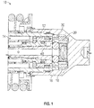
- the actuator assembly 10 comprises an elongated hollow cylinder 12 defining a bore 14 therein.
- a cylinder rod end cap 16 is operatively coupled to a beveled end of the cylinder 12 and provides an annular recess 18 between it and the cylinder 12.
- a piston is slidably received in the bore 14 of the cylinder 12.
- a rod portion 20 of the piston projects from a rod end of the cylinder 12 and is adapted to provide a pushing action in a direction away from the cylinder head end or a pulling action in a direction toward the cylinder head end.
- the actuator assembly is disposed on an aircraft and is a deployment actuator associated with a ram air turbine.
- the actuator assembly interacts with the ram air turbine and controls a position of a door on the aircraft.
- FIG. 1 illustrates the actuator assembly 10 in a first position (e.g., stowed position) and
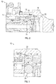
- FIG. 2 illustrates the actuator assembly 10 in a second position (e.g., deploying position).
- At least one locking pawl 30 is slidably disposed in radial apertures. In the illustrated embodiment, two locking pawls are illustrated, but it is to be appreciated that one or more pawls may be included.
- the outer ends of the pawl 30 includes beveled surfaces 32 for engaging and cooperating with a beveled surface 33 on the end of the cylinder 12.
- the inner end of the pawl 30 is provided with a sloped surface 36 terminating in a substantially flat surface 38.
- a lock bolt 40 is axially displaced and held in this position by retraction of the pawl 32 which is confined in the inward radial direction by the cylinder 12.
- the fluid pressure drives the cylinder 12 into its retracted position and the lock bolt 40 into its latching position with rollers beneath the pawl.
- the pawl 30 includes multiple interfaces with other components where frictional forces occur.
- interfaces 42 and 44 represent locations where sliding friction occurs and interface 46 represents a location where rolling friction occurs.
- the coefficient of friction at these locations is determined by component geometry and material properties. The coefficient of friction must be such that self-locking of the components does not occur, where self-locking is defined by a condition where the friction forces inhibit or prevent relative movement of the components subjected to the frictional forces, thereby impairing operation of the actuator assembly 10.
- a method of manufacturing the components of the actuator assembly 10 are disclosed herein, with the method ensuring that the coefficient of friction at each interface 42, 44 and 46 is suitable for operation of the actuator assembly 10. It has been empirically determined that tumble polishing the pawl surfaces at the interface locations 42, 44 and 46 results in a coefficient of friction that is suitable. As such, the surfaces of the pawl 32, the cylinder 12 and the rod 20 are tumble polished. In some embodiments, the segments of the components are tumble polished as individual segments.
- the method includes verifying that tumble polishing has occurred with the use of a surface finish analyzer to measure specific parameters. This excludes the possibility of accepting a machined surface that has not been tumble polished based on conventional surface finish measurements.
- the surface finish analyzer may be selected from numerous acceptable lab instruments. In some embodiments, the surface finish analyzer is a profilometer with a stylus tip, for example, however, alternatives are contemplated. Regardless of the precise surface finish analyzer employed, at least one bearing ratio measurement is taken and compared to a pre-determined minimum bearing ratio value to verify that tumble polishing has occurred.
- the components associated with interfaces 42, 44 and 46 are polished in their entireties as individual segments.
- at least one bearing ratio measurement is taken, but in some embodiments two or more readings are required.
- the surface finish measurements are made over a minimum of two sampling lengths whose cutoff ranges from about 0.010 inches to about 0.030 inches.
- the minimum bearing ratio measurement must be 50 percent at 10.0 microinches cut depth measured down from a 5% reference line.
- suitable coefficient of friction is verified at each interface 42, 44 and 46.
- This provides consistent deployment of the actuator assembly and improved margin from self-locking coefficient of friction.
- surface finish variation is reduced by providing more repeatable surface finish results.
- the method disclosed herein also reduces risk associated with altering geometry of the components (e.g., surface angles) since the operation is performed by a tumbling machine rather than by hand polishing.
Landscapes
- Engineering & Computer Science (AREA)
- Mechanical Engineering (AREA)
- Physics & Mathematics (AREA)
- General Physics & Mathematics (AREA)
- Aviation & Aerospace Engineering (AREA)
- Chemical & Material Sciences (AREA)
- Life Sciences & Earth Sciences (AREA)
- Analytical Chemistry (AREA)
- Biochemistry (AREA)
- General Health & Medical Sciences (AREA)
- Health & Medical Sciences (AREA)
- Immunology (AREA)
- Pathology (AREA)
- Automation & Control Theory (AREA)
- Sliding-Contact Bearings (AREA)
Abstract
Description
- The embodiments herein generally relate to actuator assembly components and, more particularly, to a method of manufacturing such components, as well as verifying a surface finish of such components.
- Actuator assemblies are used in a wide variety of applications to initiate movement of one or more components. Some actuator assemblies include a pawl that interacts with one or more components in a sliding and/or rolling manner to facilitate the desired movement of the system components. In such systems, frictional forces and rolling friction occurs during initial actuator release. Surface finish characterization at these locations plays a role in establishing the effects friction has on deployment and release margin of the actuator. More particularly, rough lay or improperly defined surface finish parameters may lead to higher than expected coefficient of friction values on key sliding surfaces which interact with each other during actuator deployment. The surface finish and the component geometry define the self-locking coefficient of friction at the interfaces. Therefore, proper material combinations for the surfaces of interest need to be chosen to ensure the overall coefficient of friction is well below a self-locking value. Unfortunately, a surface finish may appear to be adequately machined or finished, but in fact is not properly verified.
- According to one embodiment, a method of manufacturing an actuator assembly component is provided. The method includes tumble polishing the actuator assembly component. The method also includes taking at least one bearing ratio measurement along a portion of a surface of the actuator assembly component. The method further includes comparing the at least one bearing ratio measurement to a pre-determined minimum bearing ratio value to verify that the actuator assembly component has been tumble polished.
- According to another embodiment, a method of verifying a surface finish of an actuator assembly component is provided. The method includes taking at least one bearing ratio measurement along a portion of a surface of the actuator assembly component. The method also includes comparing the at least one bearing ratio measurement to a pre-determined minimum bearing ratio value to determine if the actuator assembly component has been tumble polished.
- The subject matter which is regarded as the invention is particularly pointed out and distinctly claimed in the claims at the conclusion of the specification. The foregoing and other features and advantages of the invention are apparent from the following detailed description taken in conjunction with the accompanying drawings in which:
-
FIG. 1 is a cross-sectional view of a portion of an actuator assembly in a first position; -
FIG. 2 is a cross-sectional view of a portion of the actuator assembly in a second position; and -
FIG. 3 is an enlarged view of a pawl of the actuator assembly illustrating frictional contact interface locations of the pawl. - Referring to
FIGS. 1 and2 , illustrated is a portion of an actuator assembly that is generally referenced withnumeral 10. Theactuator assembly 10 comprises an elongatedhollow cylinder 12 defining abore 14 therein. A cylinderrod end cap 16 is operatively coupled to a beveled end of thecylinder 12 and provides anannular recess 18 between it and thecylinder 12. A piston is slidably received in thebore 14 of thecylinder 12. Arod portion 20 of the piston projects from a rod end of thecylinder 12 and is adapted to provide a pushing action in a direction away from the cylinder head end or a pulling action in a direction toward the cylinder head end. - In some embodiments, the actuator assembly is disposed on an aircraft and is a deployment actuator associated with a ram air turbine. In such embodiments, the actuator assembly interacts with the ram air turbine and controls a position of a door on the aircraft. In the illustrated embodiments,
FIG. 1 illustrates theactuator assembly 10 in a first position (e.g., stowed position) andFIG. 2 illustrates theactuator assembly 10 in a second position (e.g., deploying position). Although described in the aircraft example above, it is to be appreciated that the embodiments disclosed herein may benefit numerous applications that have sliding interfaces with critical coefficient of frictions associated with them. - Referring now to
FIG. 3 , with continued reference toFIGS. 1 and2 , a portion of theactuator assembly 10 is illustrated in greater detail. At least onelocking pawl 30 is slidably disposed in radial apertures. In the illustrated embodiment, two locking pawls are illustrated, but it is to be appreciated that one or more pawls may be included. The outer ends of thepawl 30 includesbeveled surfaces 32 for engaging and cooperating with abeveled surface 33 on the end of thecylinder 12. The inner end of thepawl 30 is provided with asloped surface 36 terminating in a substantiallyflat surface 38. - In operation, in order to retract and lock the actuator in the retracted position, hydraulic or other fluid pressure is introduced to the
bore 14 of thecylinder 12. At this time, alock bolt 40 is axially displaced and held in this position by retraction of thepawl 32 which is confined in the inward radial direction by thecylinder 12. The fluid pressure drives thecylinder 12 into its retracted position and thelock bolt 40 into its latching position with rollers beneath the pawl. Thepawl 30 includes multiple interfaces with other components where frictional forces occur. In particular,interfaces interface 46 represents a location where rolling friction occurs. The coefficient of friction at these locations is determined by component geometry and material properties. The coefficient of friction must be such that self-locking of the components does not occur, where self-locking is defined by a condition where the friction forces inhibit or prevent relative movement of the components subjected to the frictional forces, thereby impairing operation of theactuator assembly 10. - A method of manufacturing the components of the
actuator assembly 10 are disclosed herein, with the method ensuring that the coefficient of friction at eachinterface actuator assembly 10. It has been empirically determined that tumble polishing the pawl surfaces at theinterface locations pawl 32, thecylinder 12 and therod 20 are tumble polished. In some embodiments, the segments of the components are tumble polished as individual segments. - To prevent an improper visual verification of the surfaces or improper verification using conventional surface analysis techniques from occurring, the method includes verifying that tumble polishing has occurred with the use of a surface finish analyzer to measure specific parameters. This excludes the possibility of accepting a machined surface that has not been tumble polished based on conventional surface finish measurements. The surface finish analyzer may be selected from numerous acceptable lab instruments. In some embodiments, the surface finish analyzer is a profilometer with a stylus tip, for example, however, alternatives are contemplated. Regardless of the precise surface finish analyzer employed, at least one bearing ratio measurement is taken and compared to a pre-determined minimum bearing ratio value to verify that tumble polishing has occurred.
- In some embodiments, the components associated with
interfaces - Advantageously, suitable coefficient of friction is verified at each
interface - While the invention has been described in detail in connection with only a limited number of embodiments, it should be readily understood that the invention is not limited to such disclosed embodiments. Rather, the invention can be modified to incorporate any number of variations, alterations, substitutions or equivalent arrangements not heretofore described, but which are commensurate with the scope of the invention. Additionally, while various embodiments of the invention have been described, it is to be understood that aspects of the invention may include only some of the described embodiments. Accordingly, the invention is not to be seen as limited by the foregoing description, but is only limited by the scope of the appended claims.
Claims (15)
- A method of manufacturing an actuator assembly component comprising:tumble polishing the actuator assembly component;taking at least one bearing ratio measurement along a portion of a surface of the actuator assembly component; andcomparing the at least one bearing ratio measurement to a minimum bearing ratio value to verify that the actuator assembly component has been tumble polished.
- The method of claim 1, wherein the entire actuator assembly component is tumble polished.
- The method of claim 2, wherein the entire actuator assembly component is tumble polished as individual segments.
- The method of claim 1, wherein the at least one bearing ratio measurement is taken with a surface finish analyzer.
- The method of claim 4, wherein the surface finish analyzer comprises a profilometer.
- The method of claim 4, wherein the surface finish analyzer comprises a stylus tip.
- The method of claim 1, wherein the actuator assembly component is an uplock pawl of a ram air turbine disposed on an aircraft.
- The method of claim 1, wherein at least two bearing ratio measurements are taken.
- The method of claim 1, wherein the minimum bearing ratio value is 50 percent at a 10.0 microinch cut depth.
- A method of verifying a surface finish of an actuator assembly component comprising:taking at least one bearing ratio measurement along a portion of a surface of the actuator assembly component; andcomparing the at least one bearing ratio measurement to a minimum bearing ratio value to determine if the actuator assembly component has been tumble polished.
- The method of claim 10, wherein the at least one bearing ratio measurement is taken with a surface finish analyzer.
- The method of claim 11, wherein the surface finish analyzer comprises one of a profilometer and a stylus tip.
- The method of claim 10, wherein the actuator assembly component is an uplock pawl of a ram air turbine disposed on an aircraft.
- The method of claim 10, wherein at least two bearing ratio measurements are taken.
- The method of claim 10, wherein the minimum bearing ratio value is 50 percent at a 10.0 microinch cut depth.
Applications Claiming Priority (1)
| Application Number | Priority Date | Filing Date | Title |
|---|---|---|---|
| US14/887,657 US20170106498A1 (en) | 2015-10-20 | 2015-10-20 | Method of manufacturing an actuator assembly component and method of verifying surface finish |
Publications (1)
| Publication Number | Publication Date |
|---|---|
| EP3162500A1 true EP3162500A1 (en) | 2017-05-03 |
Family
ID=57184323
Family Applications (1)
| Application Number | Title | Priority Date | Filing Date |
|---|---|---|---|
| EP16194544.9A Withdrawn EP3162500A1 (en) | 2015-10-20 | 2016-10-19 | Method of manufacturing an actuator assembly component and method of verifying surface finish |
Country Status (2)
| Country | Link |
|---|---|
| US (1) | US20170106498A1 (en) |
| EP (1) | EP3162500A1 (en) |
Citations (2)
| Publication number | Priority date | Publication date | Assignee | Title |
|---|---|---|---|---|
| US5398780A (en) * | 1993-02-19 | 1995-03-21 | Sundstrand Corporation | Linear actuator with speed controlling brake |
| EP0976496A1 (en) * | 1998-07-31 | 2000-02-02 | G. Baggioli Pressofusione Europe S.r.l. | Process for reducing friction coefficient and increasing corrosion strength in components for safety belt rewinding devices |
Family Cites Families (8)
| Publication number | Priority date | Publication date | Assignee | Title |
|---|---|---|---|---|
| US5202810A (en) * | 1989-04-27 | 1993-04-13 | Hitachi, Ltd. | Magnetic disk having an improved surface configuration |
| US5503481A (en) * | 1993-12-09 | 1996-04-02 | The Timken Company | Bearing surfaces with isotropic finish |
| DE10327437A1 (en) * | 2002-06-24 | 2004-01-22 | Luk Lamellen Und Kupplungsbau Beteiligungs Kg | Hydraulic system e.g. for operating a motor vehicle clutch has emitter cylinder with piston made from thermosetting material |
| JP2004265461A (en) * | 2003-01-31 | 2004-09-24 | Nippon Sheet Glass Co Ltd | Glass substrate for information recording medium and its manufacturing method |
| US8323072B1 (en) * | 2007-03-21 | 2012-12-04 | 3M Innovative Properties Company | Method of polishing transparent armor |
| US8172716B2 (en) * | 2009-06-25 | 2012-05-08 | United Technologies Corporation | Epicyclic gear system with superfinished journal bearing |
| CN104160146A (en) * | 2011-10-28 | 2014-11-19 | 雷姆技术公司 | Wind turbine gearbox lubrication system |
| SG11201501455YA (en) * | 2012-09-28 | 2015-05-28 | Hoya Corp | Magnetic-disk glass substrate, magnetic disk and method for manufacturing magnetic-disk glass substrate |
-
2015
- 2015-10-20 US US14/887,657 patent/US20170106498A1/en not_active Abandoned
-
2016
- 2016-10-19 EP EP16194544.9A patent/EP3162500A1/en not_active Withdrawn
Patent Citations (2)
| Publication number | Priority date | Publication date | Assignee | Title |
|---|---|---|---|---|
| US5398780A (en) * | 1993-02-19 | 1995-03-21 | Sundstrand Corporation | Linear actuator with speed controlling brake |
| EP0976496A1 (en) * | 1998-07-31 | 2000-02-02 | G. Baggioli Pressofusione Europe S.r.l. | Process for reducing friction coefficient and increasing corrosion strength in components for safety belt rewinding devices |
Non-Patent Citations (1)
| Title |
|---|
| ZYGO CORPORATION: "MetroPro(TM) Surface Texture Parameters", INTERNET CITATION, June 2005 (2005-06-01), XP002460415, Retrieved from the Internet <URL:http://www.zygo.com/library/papers/SurfText.pdf> [retrieved on 20070101] * |
Also Published As
| Publication number | Publication date |
|---|---|
| US20170106498A1 (en) | 2017-04-20 |
Similar Documents
| Publication | Publication Date | Title |
|---|---|---|
| US8336222B1 (en) | Method and apparatus for measuring spaces with limited access | |
| US8561705B2 (en) | Lead impression wear bushing | |
| CN107278260B (en) | Hole inspection device | |
| EP2985472B1 (en) | Stow lock pawl for a rat actuator | |
| US20180023939A1 (en) | Retractable index pins and methods of operating thereof | |
| JP7846814B2 (en) | Multi-piece fastener, multi-piece fastener installation device, and fastening method | |
| US7552627B2 (en) | Brake wear measurement apparatus and method | |
| CA2581457C (en) | Thread gauging system and method | |
| CN106274838A (en) | Rain brush prosthetic device | |
| US20170106498A1 (en) | Method of manufacturing an actuator assembly component and method of verifying surface finish | |
| EP3207351A1 (en) | Coating bond test method and method of making a specimen for testing bond strength of a coating | |
| US10215546B2 (en) | Rotor profile comparator | |
| US10481047B2 (en) | Apparatus and method for testing a linear acuator | |
| US10519998B2 (en) | Expansion anchor having a double coating | |
| EP3076034A1 (en) | Track roller bearing | |
| US11614112B2 (en) | Temporary clamping fastener with expandable clamp blade | |
| WO2016087641A1 (en) | Releasable ratchet device | |
| US6990859B2 (en) | Locking mechanism for load analyzer | |
| CN210486737U (en) | Tool for detecting height of spring seat ring | |
| CN104458463B (en) | Method for evaluating material sub-surface machining damage layer thickness | |
| US20180038349A1 (en) | Release mechanism | |
| RU2606145C1 (en) | Method of hollow cylinders processing | |
| Kainer | Identification of methods and means of monitoring precision components in finishing operations and following manufacture | |
| GB2581618A (en) | Methods and assemblies for running and testing tools |
Legal Events
| Date | Code | Title | Description |
|---|---|---|---|
| PUAI | Public reference made under article 153(3) epc to a published international application that has entered the european phase |
Free format text: ORIGINAL CODE: 0009012 |
|
| STAA | Information on the status of an ep patent application or granted ep patent |
Free format text: STATUS: THE APPLICATION HAS BEEN PUBLISHED |
|
| AK | Designated contracting states |
Kind code of ref document: A1 Designated state(s): AL AT BE BG CH CY CZ DE DK EE ES FI FR GB GR HR HU IE IS IT LI LT LU LV MC MK MT NL NO PL PT RO RS SE SI SK SM TR |
|
| AX | Request for extension of the european patent |
Extension state: BA ME |
|
| STAA | Information on the status of an ep patent application or granted ep patent |
Free format text: STATUS: REQUEST FOR EXAMINATION WAS MADE |
|
| RIN1 | Information on inventor provided before grant (corrected) |
Inventor name: BANNON, DAVID G. Inventor name: CHODAKOWSKI, PAWEL P. |
|
| 17P | Request for examination filed |
Effective date: 20171026 |
|
| RBV | Designated contracting states (corrected) |
Designated state(s): AL AT BE BG CH CY CZ DE DK EE ES FI FR GB GR HR HU IE IS IT LI LT LU LV MC MK MT NL NO PL PT RO RS SE SI SK SM TR |
|
| STAA | Information on the status of an ep patent application or granted ep patent |
Free format text: STATUS: EXAMINATION IS IN PROGRESS |
|
| 17Q | First examination report despatched |
Effective date: 20200421 |
|
| STAA | Information on the status of an ep patent application or granted ep patent |
Free format text: STATUS: THE APPLICATION IS DEEMED TO BE WITHDRAWN |
|
| 18D | Application deemed to be withdrawn |
Effective date: 20210501 |