EP3160070A1 - Multi-stage encoding device, method for implementing multi-stage encoding device and storage medium - Google Patents
Multi-stage encoding device, method for implementing multi-stage encoding device and storage medium Download PDFInfo
- Publication number
- EP3160070A1 EP3160070A1 EP14896157.6A EP14896157A EP3160070A1 EP 3160070 A1 EP3160070 A1 EP 3160070A1 EP 14896157 A EP14896157 A EP 14896157A EP 3160070 A1 EP3160070 A1 EP 3160070A1
- Authority
- EP
- European Patent Office
- Prior art keywords
- encoder
- selection switch
- input
- output
- input end
- Prior art date
- Legal status (The legal status is an assumption and is not a legal conclusion. Google has not performed a legal analysis and makes no representation as to the accuracy of the status listed.)
- Granted
Links
Images


Classifications
-
- H—ELECTRICITY
- H04—ELECTRIC COMMUNICATION TECHNIQUE
- H04L—TRANSMISSION OF DIGITAL INFORMATION, e.g. TELEGRAPHIC COMMUNICATION
- H04L1/00—Arrangements for detecting or preventing errors in the information received
-
- H—ELECTRICITY
- H03—ELECTRONIC CIRCUITRY
- H03M—CODING; DECODING; CODE CONVERSION IN GENERAL
- H03M13/00—Coding, decoding or code conversion, for error detection or error correction; Coding theory basic assumptions; Coding bounds; Error probability evaluation methods; Channel models; Simulation or testing of codes
- H03M13/25—Error detection or forward error correction by signal space coding, i.e. adding redundancy in the signal constellation, e.g. Trellis Coded Modulation [TCM]
-
- H—ELECTRICITY
- H03—ELECTRONIC CIRCUITRY
- H03M—CODING; DECODING; CODE CONVERSION IN GENERAL
- H03M13/00—Coding, decoding or code conversion, for error detection or error correction; Coding theory basic assumptions; Coding bounds; Error probability evaluation methods; Channel models; Simulation or testing of codes
- H03M13/25—Error detection or forward error correction by signal space coding, i.e. adding redundancy in the signal constellation, e.g. Trellis Coded Modulation [TCM]
- H03M13/251—Error detection or forward error correction by signal space coding, i.e. adding redundancy in the signal constellation, e.g. Trellis Coded Modulation [TCM] with block coding
-
- H—ELECTRICITY
- H03—ELECTRONIC CIRCUITRY
- H03M—CODING; DECODING; CODE CONVERSION IN GENERAL
- H03M13/00—Coding, decoding or code conversion, for error detection or error correction; Coding theory basic assumptions; Coding bounds; Error probability evaluation methods; Channel models; Simulation or testing of codes
- H03M13/25—Error detection or forward error correction by signal space coding, i.e. adding redundancy in the signal constellation, e.g. Trellis Coded Modulation [TCM]
- H03M13/255—Error detection or forward error correction by signal space coding, i.e. adding redundancy in the signal constellation, e.g. Trellis Coded Modulation [TCM] with Low Density Parity Check [LDPC] codes
-
- H—ELECTRICITY
- H03—ELECTRONIC CIRCUITRY
- H03M—CODING; DECODING; CODE CONVERSION IN GENERAL
- H03M13/00—Coding, decoding or code conversion, for error detection or error correction; Coding theory basic assumptions; Coding bounds; Error probability evaluation methods; Channel models; Simulation or testing of codes
- H03M13/25—Error detection or forward error correction by signal space coding, i.e. adding redundancy in the signal constellation, e.g. Trellis Coded Modulation [TCM]
- H03M13/256—Error detection or forward error correction by signal space coding, i.e. adding redundancy in the signal constellation, e.g. Trellis Coded Modulation [TCM] with trellis coding, e.g. with convolutional codes and TCM
-
- H—ELECTRICITY
- H03—ELECTRONIC CIRCUITRY
- H03M—CODING; DECODING; CODE CONVERSION IN GENERAL
- H03M13/00—Coding, decoding or code conversion, for error detection or error correction; Coding theory basic assumptions; Coding bounds; Error probability evaluation methods; Channel models; Simulation or testing of codes
- H03M13/29—Coding, decoding or code conversion, for error detection or error correction; Coding theory basic assumptions; Coding bounds; Error probability evaluation methods; Channel models; Simulation or testing of codes combining two or more codes or code structures, e.g. product codes, generalised product codes, concatenated codes, inner and outer codes
-
- H—ELECTRICITY
- H03—ELECTRONIC CIRCUITRY
- H03M—CODING; DECODING; CODE CONVERSION IN GENERAL
- H03M13/00—Coding, decoding or code conversion, for error detection or error correction; Coding theory basic assumptions; Coding bounds; Error probability evaluation methods; Channel models; Simulation or testing of codes
- H03M13/29—Coding, decoding or code conversion, for error detection or error correction; Coding theory basic assumptions; Coding bounds; Error probability evaluation methods; Channel models; Simulation or testing of codes combining two or more codes or code structures, e.g. product codes, generalised product codes, concatenated codes, inner and outer codes
- H03M13/2945—Coding, decoding or code conversion, for error detection or error correction; Coding theory basic assumptions; Coding bounds; Error probability evaluation methods; Channel models; Simulation or testing of codes combining two or more codes or code structures, e.g. product codes, generalised product codes, concatenated codes, inner and outer codes using at least three error correction codes
-
- H—ELECTRICITY
- H03—ELECTRONIC CIRCUITRY
- H03M—CODING; DECODING; CODE CONVERSION IN GENERAL
- H03M13/00—Coding, decoding or code conversion, for error detection or error correction; Coding theory basic assumptions; Coding bounds; Error probability evaluation methods; Channel models; Simulation or testing of codes
- H03M13/35—Unequal or adaptive error protection, e.g. by providing a different level of protection according to significance of source information or by adapting the coding according to the change of transmission channel characteristics
-
- H—ELECTRICITY
- H03—ELECTRONIC CIRCUITRY
- H03M—CODING; DECODING; CODE CONVERSION IN GENERAL
- H03M13/00—Coding, decoding or code conversion, for error detection or error correction; Coding theory basic assumptions; Coding bounds; Error probability evaluation methods; Channel models; Simulation or testing of codes
- H03M13/03—Error detection or forward error correction by redundancy in data representation, i.e. code words containing more digits than the source words
- H03M13/05—Error detection or forward error correction by redundancy in data representation, i.e. code words containing more digits than the source words using block codes, i.e. a predetermined number of check bits joined to a predetermined number of information bits
- H03M13/11—Error detection or forward error correction by redundancy in data representation, i.e. code words containing more digits than the source words using block codes, i.e. a predetermined number of check bits joined to a predetermined number of information bits using multiple parity bits
- H03M13/1102—Codes on graphs and decoding on graphs, e.g. low-density parity check [LDPC] codes
-
- H—ELECTRICITY
- H03—ELECTRONIC CIRCUITRY
- H03M—CODING; DECODING; CODE CONVERSION IN GENERAL
- H03M13/00—Coding, decoding or code conversion, for error detection or error correction; Coding theory basic assumptions; Coding bounds; Error probability evaluation methods; Channel models; Simulation or testing of codes
- H03M13/03—Error detection or forward error correction by redundancy in data representation, i.e. code words containing more digits than the source words
- H03M13/05—Error detection or forward error correction by redundancy in data representation, i.e. code words containing more digits than the source words using block codes, i.e. a predetermined number of check bits joined to a predetermined number of information bits
- H03M13/13—Linear codes
- H03M13/15—Cyclic codes, i.e. cyclic shifts of codewords produce other codewords, e.g. codes defined by a generator polynomial, Bose-Chaudhuri-Hocquenghem [BCH] codes
- H03M13/151—Cyclic codes, i.e. cyclic shifts of codewords produce other codewords, e.g. codes defined by a generator polynomial, Bose-Chaudhuri-Hocquenghem [BCH] codes using error location or error correction polynomials
- H03M13/1515—Reed-Solomon codes
-
- H—ELECTRICITY
- H03—ELECTRONIC CIRCUITRY
- H03M—CODING; DECODING; CODE CONVERSION IN GENERAL
- H03M13/00—Coding, decoding or code conversion, for error detection or error correction; Coding theory basic assumptions; Coding bounds; Error probability evaluation methods; Channel models; Simulation or testing of codes
- H03M13/03—Error detection or forward error correction by redundancy in data representation, i.e. code words containing more digits than the source words
- H03M13/23—Error detection or forward error correction by redundancy in data representation, i.e. code words containing more digits than the source words using convolutional codes, e.g. unit memory codes
-
- H—ELECTRICITY
- H03—ELECTRONIC CIRCUITRY
- H03M—CODING; DECODING; CODE CONVERSION IN GENERAL
- H03M13/00—Coding, decoding or code conversion, for error detection or error correction; Coding theory basic assumptions; Coding bounds; Error probability evaluation methods; Channel models; Simulation or testing of codes
- H03M13/29—Coding, decoding or code conversion, for error detection or error correction; Coding theory basic assumptions; Coding bounds; Error probability evaluation methods; Channel models; Simulation or testing of codes combining two or more codes or code structures, e.g. product codes, generalised product codes, concatenated codes, inner and outer codes
- H03M13/2957—Turbo codes and decoding
Definitions
- the disclosure relates to data transmission technology in a microwave communication system, and in particular to a multi-stage encoding device, a method for implementing the multi-stage encoding device and a storage medium.
- Microwave communication together with optical fibre communication and satellite communication, is considered as three main means of modern communication transmission; and the microwave communication adopts generally a point-to-point transmission mode, with applied mainly to a 2G/3G mobile carrying network, to provide speech and data service transmission for mobile operators, and is characterized by a large transmission capacity, a stable quality of transmission, a low investment, a short construction cycle, and maintenance convenience and so on.
- An encoding scheme in the microwave communication can be implemented through Low Density Parity Check Code (LDPC) encoding or Reed-Solomon code (RS) encoding;
- LDPC Low Density Parity Check Code
- RS Reed-Solomon code
- the LDPC encoding has advantages of good performance of approaching the Shannon limit, a low decoding complexity, and a flexible structure and so on, but an error floor occurs easily in the LDPC encoding;
- the RS encoding is a low-speed channel encoding of forward error correction and is only valid for a multinomial generated by corrected sampled data.
- a convolutional code encoding is to encode continuously input information sequences so as to obtain continuously output encoded sequences; a Turbo code encoding can perform subtly a parallel concatenation on two simple component codes through a pseudorandom interleaver so as to construct them as a long code with a pseudorandom characteristic.
- Each of the encoding modes has respective advantages and disadvantages, so a problem to be solved is to provide an encoding mode that improves encoding efficiency and reliability.
- embodiments of the disclosure are desired to provide a multi-stage encoding device, a method for implementing the multi-stage encoding device and a storage medium, which can improve the encoding efficiency and reliability.
- An embodiment of the disclosure provides a multi-stage encoding device including a first encoder and a second encoder, an input end of the first encoder is connected to a data input end, an output end of the first encoder is connected to a constellation mapper via an output selection switch, and the output end of the first encoder is connected to a first input end of an input selection switch; a second input end of the input selection switch is connected to the data input end, and an output end of the input selection switch is connected to an input end of the second encoder; an output end of the second encoder is connected to the constellation mapper; and an on/off state of the output selection switch enables the input selection switch to switch on different input ends.
- the input selection switch when the output selection switch is in the on state, switches the second input end on, and the first encoder and the second encoder are connected in parallel.
- the input selection switch when the output selection switch is in the off state, switches the first input end on, and the first encoder and the second encoder are connected in series.
- the first encoder is a Reed-Solomon (RS) encoder
- the second encoder is a Low Density Parity Check Code (LDPC) encoder.
- RS Reed-Solomon
- LDPC Low Density Parity Check Code
- An embodiment of the disclosure provides another multi-stage encoding device including a first encoder, a second encoder and at least one third encoder, an input end of the first encoder is connected to a data input end, an output end of the first encoder is connected to a constellation mapper via a first output selection switch, and the output end of the first encoder is connected to a first input end of a first input selection switch, a second input end of the first input selection switch is connected to the data input end, and an output end of the first input selection switch is connected to an input end of the third encoder and a second input end of a second input selection switch; an output end of the third encoder is connected to the constellation mapper via a second output selection switch, and the output end of the third encoder is connected to a first input end of the second input selection switch, a third input end of the second input selection switch is connected to the data input end, an output end of the second input selection switch is connected to an input end of the second encoder, and an output end of the second encoder is connected to the
- the first output selection switch when the first output selection switch is in the on state, the first input selection switch switches the second input end on, the second output selection switch is in the on state, the second input selection switch switches the third input end on, and the first encoder, the second encoder and the third encoder are connected in parallel.
- the first output selection switch when the first output selection switch is in the off state, the first input selection switch switches the first input end on, the second output selection switch is in the on state, the second input selection switch switches the third input end on, and the first encoder and the third encoder are connected in series with each other and are connected in parallel with the second encoder.
- the first output selection switch when the first output selection switch is in the off state, the first input selection switch switches the first input end on, the second output selection switch is in the off state, the second input selection switch switches the first input end on, and the first encoder, the second encoder and the third encoder are connected in series.
- the first output selection switch when the first output selection switch is in the on state, the first input selection switch switches the second input end on, the second output selection switch is in the off state, the second input selection switch switches the first input end on, and the second encoder and the third encoder are connected in series with each other and are connected in parallel with the first encoder.
- the first output selection switch when the first output selection switch is in the off state, the first input selection switch switches the first input end on, the second output selection switch is in the off state, the second input selection switch switches the second input end on, and the first encoder and the second encoder are connected in series.
- the first output selection switch when the first output selection switch is in the on state, the first input selection switch switches the second input end on, the second output selection switch is in the off state, the second input selection switch switches the third input end on, and the first encoder and the second encoder are connected in parallel.
- the first output selection switch when the first output selection switch is in the off state, the first input selection switch switches the second input end on, the second output selection switch is in the off state, the second input selection switch switches the first input end on, and the second encoder and the third encoder are connected in series.
- the first output selection switch when the first output selection switch is in the off state, the first input selection switch switches the second input end on, the second output selection switch is in the on state, the second input selection switch switches the third input end on, and the second encoder and the third encoder are connected in parallel.
- the first output selection switch when the first output selection switch is in the off state, the first input selection switch switches the first input end on, the second output selection switch is in the on state, the second input selection switch switches the first input end or the second input end on, and the first encoder and the third encoder are connected in series.
- the first output selection switch when the first output selection switch is in the on state, the first input selection switch switches the second input end on, the second output selection switch is in the on state, the second input selection switch switches the first input end or the second input end on, and the first encoder and the third encoder are connected in parallel.
- the third encoder includes a number of third encoders, which is equal to N, for each of the third encoders, an output end of said third encoder is connected to the constellation mapper via a respective output selection switch, and an input end of said third encoder is connected to an output end of a respective input selection switch, where N is greater than 1; an input end of a first one of the third encoders is connected to the output end of the first input selection switch, and an output end of the first one of the third encoders is connected to the first input end of the second input selection switch; an input end of an ith one of the third encoders is connected to an output end of an ith input selection switch, where i is greater than or equal to 2 and less than N; an output end of the ith one of the third encoders is connected to a first input end of an (i+1)th input selection switch; a number of the input ends of the ith input selection switch is equal to i+1, an (i+1)th input end of the ith input selection switch is connected
- the first encoder is a Reed-Solomon (RS) encoder
- the second encoder is a Low Density Parity Check Code (LDPC) encoder
- the third encoder is a convolution encoder or a Turbo encoder.
- An embodiment of the disclosure further provides a method for implementing a multi-stage encoding device, the method includes providing an input selection switch and an output selection switch between input and output ends of first and second encoders, and enabling the first encoder and the second encoder to encode in parallel or in series by controlling the output selection switch and the input selection switch.
- the first encoder and the second encoder are enabled to encode in parallel, when the output end of the first encoder and a constellation mapper are connected by the output selection switch and the input end of the second encoder and a data input end are connected by the input selection switch.
- the first encoder and the second encoder are enabled to encode in series, when an output end of the output selection switch is connected to an input end of the input selection switch to enable the output end of the first encoder and the input end of the second encoder to be connected.
- the first encoder is a Reed-Solomon (RS) encoder
- the second encoder is a Low Density Parity Check Code (LDPC) encoder.
- RS Reed-Solomon
- LDPC Low Density Parity Check Code
- An embodiment of the disclosure further provides another method for implementing a multi-stage encoding device including providing a first output selection switch and a first input selection switch between an input end and an output end of a first encoder and a third encoder; providing a second output selection switch and a second input selection switch between an input end and an output end of the third encoder and a second encoder; and enabling the first encoder, the second encoder and the third encoder to encode in series or in parallel by controlling the first output selection switch, the first input selection switch, the second output selection switch and the second input selection switch.
- the third encoder includes a number of third encoders, which is equal to N, an output end of each of the third encoders is connected to a constellation mapper via a respective output selection switch, and an input end of each of the third encoders is connected to an output end of a respective input selection switch, where N is greater than 1; and said enabling includes:
- the first encoder is a Reed-Solomon code (RS) encoder
- the second encoder is a Low Density Parity Check Code (LDPC) encoder
- the third encoder is a convolution encoder or a Turbo encoder.
- An embodiment of the disclosure further provides a computer storage medium in which a computer executable instruction is stored for performing the method for implementing the multi-stage encoding device as described above according to the embodiments of the disclosure.
- the input selection switch and the output selection switch are provided between input and output ends of two encoders, and the two encoders are enabled to encode in parallel or in series by controlling the output selection switch and the input selection switch; or for multiple encoders, the input selection switch and the output selection switch are provided between the input end and the output end of every two neighboring encoders respectively, and the multiple encoders are enabled to encode in parallel or in series by controlling each output selection switch and each input selection switch; in this way, parallel encoding or serial encoding can be made among multiple encoders by controlling the on/off state of each input selection switch and each output selection switch or the selection of the input end, so the weakness under a condition that a single encoder performs the encoding can be remedied, and thus the encoding efficiency and reliability can be improved.
- an input selection switch and an output selection switch are provided between input and output ends of two encoders, and these two encoders are enabled to encode in parallel or in series by controlling the output selection switch and the input selection switch; or for multiple encoders, the input selection switch and the output selection switch are provided between the input end and the output end of every two neighboring encoders respectively, and the multiple encoders are enabled to encode in parallel or in series by controlling each output selection switch and each input selection switch.
- the encoders include, but are not limited to, a RS encoder, a LDPC encoder, a convolution encoder and a Turbo encoder.
- the composition structure of a multi-stage encoding device in an embodiment of the disclosure includes a first encoder 10 and a second encoder 20; an input end of the first encoder 10 is connected to a data input end, an output end of the first encoder 10 is connected to a constellation map mapper via an output selection switch 11, and the output end of the first encoder 10 is connected to a first input end of an input selection switch 21; a second input end of the input selection switch 21 is connected to the data input end, and an output end of the input selection switch 21 is connected to an input end of the second encoder 20; an output end of the second encoder 20 is connected to a constellation map mapper 30; and an on/off state of the output selection switch 11 enables the input selection switch 21 to switch on different input ends.
- the input selection switch 21 switches the second input end on, and the first encoder 10 and the second encoder 20 are connected in parallel.
- the input selection switch 21 switches the first input end on, and the first encoder 10 and the second encoder 20 are connected in series.
- the first encoder 10 is the RS encoder
- the second encoder 20 is the LDPC encoder
- the composition structure of another multi-stage encoding device in an embodiment of the disclosure includes a first encoder 10, a second encoder 20 and at least one third encoder 40; the input end of the first encoder 10 is connected to the data input end, the output end of the first encoder 10 is connected to the constellation map mapper 30 via the first output selection switch 31, and the output end of the first encoder 10 is connected to a first input end of a first input selection switch 41; the second input end of the first input selection switch 41 is connected to the data input end, and the output end of the first input selection switch 41 is connected to an input end of the third encoder 40 and a second input end of a second input selection switch 61; an output end of the third encoder 40 is connected to the constellation map mapper 30 via a second output selection switch 51, and the output end of the third encoder 40 is connected to a first input end of the second input selection switch 61; a third input end of the second input selection switch 61 is connected to the data input end, an output end of
- the first output selection switch 31 when the first output selection switch 31 is in the on state, the first input selection switch 41 switches the second input end on, the second output selection switch 51 is in an on state, the second input selection switch 61 switches the third input end on, and the first encoder 10, the second encoder 20 and the third encoder 40 are connected in parallel.
- the first output selection switch 31 when the first output selection switch 31 is in the off state, the first input selection switch 41 switches the first input end on, the second output selection switch 51 is in the on state, the second input selection switch 61 switches the third input end on, the first encoder 10 and the third encoder 40 are connected in series with each other and are connected in parallel with the second encoder 20.
- the first output selection switch 31 when the first output selection switch 31 is in the off state, the first input selection switch 41 switches the first input end on, the second output selection switch 51 is in the off state, the second input selection switch 61 switches the first input end on, and the first encoder 10, the second encoder 20 and the third encoder 40 are connected in series.
- the first output selection switch 31 when the first output selection switch 31 is in the on state, the first input selection switch 41 switches the second input end on, the second output selection switch 51 is in the off state, the second input selection switch 61 switches the first input end on, and the second encoder 20 and the third encoder 40 are connected in series with each other and are connected in parallel with the first encoder 10.
- the first output selection switch 31 when the first output selection switch 31 is in the off state, the first input selection switch 41 switches the first input end on, the second output selection switch 51 is in the off state, the second input selection switch 61 switches the second input end on, and the first encoder 10 and the second encoder 20 are connected in series.
- the first output selection switch 31 when the first output selection switch 31 is in the on state, the first input selection switch 41 switches the second input end on, the second output selection switch 51 is in the off state, the second input selection switch 61 switches the third input end on, and the first encoder 10 and the second encoder 20 are connected in parallel.
- the first output selection switch 31 when the first output selection switch 31 is in the off state, the first input selection switch 41 switches the second input end on, the second output selection switch 51 is in the off state, the second input selection switch 61 switches the first input end on, and the second encoder 20 and the third encoder 40 are connected in series.
- the first output selection switch 31 when the first output selection switch 31 is in the off state, the first input selection switch 41 switches the second input end on, the second output selection switch 51 is in the on state, the second input selection switch 61 switches the third input end on, and the second encoder 20 and the third encoder 40 are connected in parallel.
- the first output selection switch 31 when the first output selection switch 31 is in the off state, the first input selection switch 41 switches the first input end on, the second output selection switch 51 is in the on state, the second input selection switch 61 switches the first input end or the second input end on, and the first encoder 10 and the third encoder 40 are connected in series.
- the first output selection switch 31 when the first output selection switch 31 is in the on state, the first input selection switch 41 switches the second input end on, the second output selection switch 51 is in the on state, the second input selection switch 61 switches the first input end or the second input end on, and the first encoder 10 and the third encoder 40 are connected in parallel.
- the third encoder includes a number of third encoders 40, which is equal to N, an output end of each of the third encoders 40 is connected to the constellation map mapper via one output selection switch, and an input end of each of the third encoders 40 is connected to an output end of one input selection switch, where N is greater than 1; as shown in Fig.
- the composition structure of yet another multi-stage encoding device of an embodiment of the disclosure includes a first encoder 10, a second encoder 20 and a number N of third encoders 40; the input end of a first one of the third encoders 401 is connected to the output end of the first input selection switch 41; the output end of the first one of the third encoders 401 is connected to the first input end of the second input selection switch 61; an input end of an ith one of the third encoders 40i is connected to an output end of an ith input selection switch, where i is greater than or equal to 2 and less than N; an output end of the ith one of the third encoders 40i is connected to a first input end of an (i+1)th input selection switch; a number of the input ends of the ith input selection switch is equal to i+1; an (i+1)th input end of the ith input selection switch is connected to the data input end; second to ith input ends of the ith input selection switch are connected with the output ends of the first input
- the first encoder is the RS encoder
- the second encoder is the LDPC encoder
- the third encoder is the Convolution encoder, the Turbo encoder, or multiple parity check code encoders other than the LDPC encoder.
- An embodiment of the disclosure further provides a method for implementing a multi-stage encoding device, in which an input selection switch and an output selection switch are provided between input and output ends of a first encoder and a second encoder; as shown in Fig. 4 , the basic implementation flow of the method includes the following steps.
- Step 101 the first encoder and the second encoder are enabled to encode in parallel or in series by controlling the output selection switch and the input selection switch; specifically, when the output end of the first encoder is connected to the constellation map mapper by the output selection switch, and the input end of the second encoder is connected to the data input end by the input selection switch, the first encoder and the second encoder encode in parallel; that is, the data encoded by the first encoder enters the second encoder, and is output after being encoded by the second encoder; when the output end of the output selection switch is connected to the input end of the input selection switch to enable the output end of the first encoder and the input end of the second encoder to be connected, the first encoder and the second encoder encode in parallel; that is, the data encoded by the first encoder and the data encoded by the second encoder are output separately; the first encoder is the RS encoder, and the second encoder is the LDPC encoder.
- Step 102 the encoded data is mapped; when the first encoder and the second encoder encode in series, and the encoded data is mapped, there is only the mapping mode of the second encoding, that is, the constellation map is directly mapped; specifically, by taking that a modulation mode is 16qam and the data after the second encoding is 4'b1101 for example, the implementation process of mapping the encoded data is as follows:
- the 2 M constellation points are divided into 2 Y constellation point subsets, and each subset contains 2 X constellation points.
- Y bits in the M bits data are filled with information bit data after the LDPC encoding, at the same time the Y bits can also be used for identifying a constellation point subset, and this portion of bits are also called a subset index; the rest X bits are filled with RS information bit data not encoded, at the same time the X bits can also be used for identifying a certain constellation point in the subset.
- the bit data not encoded is not protected by encoding, the distance between the constellation points in the subset can become very large by providing the constellation map, so the noise resisting capability of the bit data not encoded is enhanced.
- QAMY represents a corresponding constellation map mapping table when the Y bits after the LDPC encoding are modulated
- QAMX represents a corresponding constellation map mapping table when the X bits after the RS encoding are modulated.
- the basic flow that the first encoder and the second encoder are connected in parallel and the encoded data is mapped includes the following steps.
- Step 2a values of 2 x qam and 2 y qam in a full encoding are calculated respectively according to x and y bits; specifically, the structure in a full encoding can be multiplexed; for example, the values of 16qam and Quadrature Phase Shift Keying (QPSK) modulation under the LDPC encoding can be calculated respectively with 64qam(4, 2).
- QPSK Quadrature Phase Shift Keying
- Step 2b the value of 2 X qam obtained according to x bits is shifted to the left; specifically, the number of bits shifted to the left is y/2, wherein y is an even number; when the value is shifted to the left, the right vacancy is filled with zero to obtain a shift amount of a value of a basic unit.
- Step 2c the final value of mapping is calculated; specifically, the obtained shift amount and the value of 2 y qam obtained according to y bits are added to obtain the final value of mapping.
- the modulation mode is 64qam (4, 2)
- the detailed implementation flow of mapping the encoded data includes the following steps.
- Step 3c the final value of mapping 6'b110110 is calculated; specifically, the shift amounts -6 and 6 are added to the value (-1, 1) in the constellation map of qpsk (0, 2) in Fig. 8 corresponding to 2'b10 respectively, so as to obtain a constellation point coordinate (-7, 7) of the data 6'b110110, namely the modulated symbol of the data 6'b110110 is (-7, 7).
- the basic unit of the constellation map is the constellation map corresponding to y, and the units of y are arranged to different positions according to x;
- Fig. 9 is the constellation map of 64qam (4, 2) whose basic unit is qpsk (0, 2) in Fig. 7 ;
- the point connected by a solid line in Fig. 8 is the original position of qpsk (0, 2), and the units at different positions are shifts from the original position of qpsk (0, 2);
- a shift value is decided by x in (x, y), and is equal to the index*2 (y/2) in a full encoding corresponding to x.
- An embodiment of the disclosure further provides another method for implementing a multi-stage encoding device, in which a first output selection switch and a first input selection switch are provided between input and output ends of a first encoder and a third encoder; a second output selection switch and a second input selection switch are provided between input and output ends of the third encoder and a second encoder; as shown in Fig. 10 , the basic implementation flow of the method includes the following steps.
- Step 201 the first encoder, the second encoder and the third encoder are enabled to encode in series or in parallel by controlling the first output selection switch, the first input selection switch, the second output selection switch and the second input selection switch;
- the third encoder includes a number of third encoders, which is equal to N, an output end of each of the third encoders is connected to the constellation map mapper via one output selection switch, and an input end of each of the third encoders is connected to an output end of one input selection switch, where N is greater than 1,
- the first encoder, the second encoder and the number N of third encoders are enabled to encode in parallel or in series by controlling each input selection switch and each output selection switch; here, the first encoder is the RS encoder, the second encoder is the LDPC encoder, and the third encoder is the Convolution encoder, the Turbo encoder, or multiple parity check code encoders other than the LDPC encoder.
- Step 202 the encoded data is mapped; specifically, when the encoded data is output in series and the encoded data is mapped, there is only the mapping mode of the LDPC encoding, that is, the constellation map is directly mapped; when the encoded data is output in parallel and the encoded data is mapped, it is necessary to first map the data encoded by each encoder respectively, calculate all the mapping results, and finally calculate corresponding points in the constellation map.
- Step 4c the final value of mapping 8'b11011001 is calculated; specifically, the shift amounts -12 and 12 are added to the value (-1, 1) in qpsk (0, 2) in Fig. 7 corresponding to 2'b01 respectively, so as to obtain a constellation point coordinate (-13, 13) of the data 8'b11011001.
- the multi-stage encoding device includes N third encoders, if N is greater than or equal to 2, the same recursion mode as recited in Step 4c would be adopted to perform the modulation.
- the method for implementing a multi-stage encoding modulation device supports a full encoding modulation mode and a parallel encoding modulation mode; in the full encoding modulation mode, the data entering the constellation map mapper is the data after the LDPC encoding, and the modulation mode includes 11 full encoding modulation modes from qpsk to 4096QAM; in the parallel encoding modulation mode, a part of the data entering the constellation map mapper is the data after multiple encoding modes, and other than the 11 full encoding modulation modes from qpsk to 4096QAM, part encoding modulation modes of the 11 full encoding modulation modes are also included, such as qpsk (1, 1), 16qam (2, 2), 32qam (3, 2), 32qam (2, 3), 64qam (4, 2), 64QAM (2, 4), 4096qam (10, 2), 4096qam (2, 10); so the modulation mode is flexible.
- the multi-stage encoding device of an embodiment of the disclosure has a simple structure, reduces the design complexity by multiplexing circuits in different modulation modes, and reduces hardware resources; besides, the output mapping symbol rate can be matched to the extent that a full-rate output can be supported, so the demand of a high-throughput scenario can be met.
- the message transmission method is implemented in a form of software function modules, and the software function modules are sold or used as independent products, they can also be stored in a computer readable storage medium.
- the technical solutions of the embodiments of the disclosure in the nature or with the part making a contribution to the prior art can be embodied in the form of a software product; the computer software product is stored in a storage medium and includes a number of instructions to cause a computer device (which may be a personal computer, a server or a network device, etc.) perform all or part of the method in each of the embodiments of the disclosure.
- the above-described storage medium includes a USB flash disk, a mobile hard disk, a Read Only Memory (ROM), a magnetic disk or a compact disc, and various other media which can store program codes.
- ROM Read Only Memory
- the embodiment of the disclosure is not limited to any particular combination of hardware and software.
- an embodiment of the disclosure further provides a computer storage medium in which a computer program is stored, the computer program is used for performing the above methods for implementing the multi-stage encoding device according to the embodiment of the disclosure.
Landscapes
- Engineering & Computer Science (AREA)
- Physics & Mathematics (AREA)
- Probability & Statistics with Applications (AREA)
- Theoretical Computer Science (AREA)
- Computer Networks & Wireless Communication (AREA)
- Signal Processing (AREA)
- Digital Transmission Methods That Use Modulated Carrier Waves (AREA)
- Error Detection And Correction (AREA)
Abstract
Description
- The disclosure relates to data transmission technology in a microwave communication system, and in particular to a multi-stage encoding device, a method for implementing the multi-stage encoding device and a storage medium.
- Microwave communication, together with optical fibre communication and satellite communication, is considered as three main means of modern communication transmission; and the microwave communication adopts generally a point-to-point transmission mode, with applied mainly to a 2G/3G mobile carrying network, to provide speech and data service transmission for mobile operators, and is characterized by a large transmission capacity, a stable quality of transmission, a low investment, a short construction cycle, and maintenance convenience and so on.
- An encoding scheme in the microwave communication can be implemented through Low Density Parity Check Code (LDPC) encoding or Reed-Solomon code (RS) encoding; the LDPC encoding has advantages of good performance of approaching the Shannon limit, a low decoding complexity, and a flexible structure and so on, but an error floor occurs easily in the LDPC encoding; the RS encoding is a low-speed channel encoding of forward error correction and is only valid for a multinomial generated by corrected sampled data. A convolutional code encoding is to encode continuously input information sequences so as to obtain continuously output encoded sequences; a Turbo code encoding can perform subtly a parallel concatenation on two simple component codes through a pseudorandom interleaver so as to construct them as a long code with a pseudorandom characteristic. Each of the encoding modes has respective advantages and disadvantages, so a problem to be solved is to provide an encoding mode that improves encoding efficiency and reliability.
- In view of this, embodiments of the disclosure are desired to provide a multi-stage encoding device, a method for implementing the multi-stage encoding device and a storage medium, which can improve the encoding efficiency and reliability.
- The technical solutions of the embodiments of the disclosure are implemented as follows.
- An embodiment of the disclosure provides a multi-stage encoding device including a first encoder and a second encoder,
an input end of the first encoder is connected to a data input end, an output end of the first encoder is connected to a constellation mapper via an output selection switch, and the output end of the first encoder is connected to a first input end of an input selection switch;
a second input end of the input selection switch is connected to the data input end, and an output end of the input selection switch is connected to an input end of the second encoder; an output end of the second encoder is connected to the constellation mapper; and
an on/off state of the output selection switch enables the input selection switch to switch on different input ends. - In an embodiment, when the output selection switch is in the on state, the input selection switch switches the second input end on, and the first encoder and the second encoder are connected in parallel.
- In an embodiment, when the output selection switch is in the off state, the input selection switch switches the first input end on, and the first encoder and the second encoder are connected in series.
- In an embodiment, the first encoder is a Reed-Solomon (RS) encoder, and the second encoder is a Low Density Parity Check Code (LDPC) encoder.
- An embodiment of the disclosure provides another multi-stage encoding device including a first encoder, a second encoder and at least one third encoder,
an input end of the first encoder is connected to a data input end, an output end of the first encoder is connected to a constellation mapper via a first output selection switch, and the output end of the first encoder is connected to a first input end of a first input selection switch,
a second input end of the first input selection switch is connected to the data input end, and an output end of the first input selection switch is connected to an input end of the third encoder and a second input end of a second input selection switch; an output end of the third encoder is connected to the constellation mapper via a second output selection switch, and the output end of the third encoder is connected to a first input end of the second input selection switch,
a third input end of the second input selection switch is connected to the data input end, an output end of the second input selection switch is connected to an input end of the second encoder, and an output end of the second encoder is connected to the constellation mapper, and
an on/off state of the first output selection switch, an on/off state of the second output selection switch and different input ends switched on by the first input selection switch enable the second input selection switch to switch on different input ends. - In an embodiment, when the first output selection switch is in the on state, the first input selection switch switches the second input end on, the second output selection switch is in the on state, the second input selection switch switches the third input end on, and the first encoder, the second encoder and the third encoder are connected in parallel.
- In an embodiment, when the first output selection switch is in the off state, the first input selection switch switches the first input end on, the second output selection switch is in the on state, the second input selection switch switches the third input end on, and the first encoder and the third encoder are connected in series with each other and are connected in parallel with the second encoder.
- In an embodiment, when the first output selection switch is in the off state, the first input selection switch switches the first input end on, the second output selection switch is in the off state, the second input selection switch switches the first input end on, and the first encoder, the second encoder and the third encoder are connected in series.
- In an embodiment, when the first output selection switch is in the on state, the first input selection switch switches the second input end on, the second output selection switch is in the off state, the second input selection switch switches the first input end on, and the second encoder and the third encoder are connected in series with each other and are connected in parallel with the first encoder.
- In an embodiment, when the first output selection switch is in the off state, the first input selection switch switches the first input end on, the second output selection switch is in the off state, the second input selection switch switches the second input end on, and the first encoder and the second encoder are connected in series.
- In an embodiment, when the first output selection switch is in the on state, the first input selection switch switches the second input end on, the second output selection switch is in the off state, the second input selection switch switches the third input end on, and the first encoder and the second encoder are connected in parallel.
- In an embodiment, when the first output selection switch is in the off state, the first input selection switch switches the second input end on, the second output selection switch is in the off state, the second input selection switch switches the first input end on, and the second encoder and the third encoder are connected in series.
- In an embodiment, when the first output selection switch is in the off state, the first input selection switch switches the second input end on, the second output selection switch is in the on state, the second input selection switch switches the third input end on, and the second encoder and the third encoder are connected in parallel.
- In an embodiment, when the first output selection switch is in the off state, the first input selection switch switches the first input end on, the second output selection switch is in the on state, the second input selection switch switches the first input end or the second input end on, and the first encoder and the third encoder are connected in series.
- In an embodiment, when the first output selection switch is in the on state, the first input selection switch switches the second input end on, the second output selection switch is in the on state, the second input selection switch switches the first input end or the second input end on, and the first encoder and the third encoder are connected in parallel.
- In an embodiment, the third encoder includes a number of third encoders, which is equal to N, for each of the third encoders, an output end of said third encoder is connected to the constellation mapper via a respective output selection switch, and an input end of said third encoder is connected to an output end of a respective input selection switch, where N is greater than 1;
an input end of a first one of the third encoders is connected to the output end of the first input selection switch, and an output end of the first one of the third encoders is connected to the first input end of the second input selection switch;
an input end of an ith one of the third encoders is connected to an output end of an ith input selection switch, where i is greater than or equal to 2 and less than N; an output end of the ith one of the third encoders is connected to a first input end of an (i+1)th input selection switch; a number of the input ends of the ith input selection switch is equal to i+1, an (i+1)th input end of the ith input selection switch is connected to the data input end; second to ith input ends of the ith input selection switch are connected with output ends of the first input selection switch to an (i-1)th input selection switch respectively;
an output end of an Nth one of the third encoders is connected to a first input end of an (N+1)th input selection switch; a number of the input ends of the (N+1)th input selection switch is equal to N+2, and an (N+2)th input end of the (N+1)th input selection switch is connected to the data input end; second to (N+1)th input ends of the (N+1)th input selection switch are connected to output ends of the first to Nth input selection switches respectively; an output end of the (N+1)th input selection switch is connected to the input end of the second encoder. - In an embodiment, the first encoder is a Reed-Solomon (RS) encoder, the second encoder is a Low Density Parity Check Code (LDPC) encoder, and the third encoder is a convolution encoder or a Turbo encoder.
- An embodiment of the disclosure further provides a method for implementing a multi-stage encoding device, the method includes providing an input selection switch and an output selection switch between input and output ends of first and second encoders, and enabling the first encoder and the second encoder to encode in parallel or in series by controlling the output selection switch and the input selection switch.
- In an embodiment, the first encoder and the second encoder are enabled to encode in parallel, when the output end of the first encoder and a constellation mapper are connected by the output selection switch and the input end of the second encoder and a data input end are connected by the input selection switch.
- In an embodiment, the first encoder and the second encoder are enabled to encode in series, when an output end of the output selection switch is connected to an input end of the input selection switch to enable the output end of the first encoder and the input end of the second encoder to be connected.
- In an embodiment, the first encoder is a Reed-Solomon (RS) encoder, and the second encoder is a Low Density Parity Check Code (LDPC) encoder.
- An embodiment of the disclosure further provides another method for implementing a multi-stage encoding device including providing a first output selection switch and a first input selection switch between an input end and an output end of a first encoder and a third encoder; providing a second output selection switch and a second input selection switch between an input end and an output end of the third encoder and a second encoder; and enabling the first encoder, the second encoder and the third encoder to encode in series or in parallel by controlling the first output selection switch, the first input selection switch, the second output selection switch and the second input selection switch.
- In an embodiment, the third encoder includes a number of third encoders, which is equal to N, an output end of each of the third encoders is connected to a constellation mapper via a respective output selection switch, and an input end of each of the third encoders is connected to an output end of a respective input selection switch, where N is greater than 1; and
said enabling includes: - enabling the first encoder, the second encoder and the N third encoders to encode in parallel or in series by controlling each input selection switch and each output selection switch.
- In an embodiment, the first encoder is a Reed-Solomon code (RS) encoder, the second encoder is a Low Density Parity Check Code (LDPC) encoder, and the third encoder is a convolution encoder or a Turbo encoder.
- An embodiment of the disclosure further provides a computer storage medium in which a computer executable instruction is stored for performing the method for implementing the multi-stage encoding device as described above according to the embodiments of the disclosure.
- According to the multi-stage encoding device, the method for implementing the multi-stage encoding device and the storage medium provided by the embodiments of the disclosure, the input selection switch and the output selection switch are provided between input and output ends of two encoders, and the two encoders are enabled to encode in parallel or in series by controlling the output selection switch and the input selection switch; or for multiple encoders, the input selection switch and the output selection switch are provided between the input end and the output end of every two neighboring encoders respectively, and the multiple encoders are enabled to encode in parallel or in series by controlling each output selection switch and each input selection switch; in this way, parallel encoding or serial encoding can be made among multiple encoders by controlling the on/off state of each input selection switch and each output selection switch or the selection of the input end, so the weakness under a condition that a single encoder performs the encoding can be remedied, and thus the encoding efficiency and reliability can be improved.
-
-
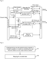
Fig. 1 is a schematic diagram of composition structure of a multi-stage encoding device according to an embodiment of the disclosure; -
Fig. 2 is a schematic diagram of composition structure of another multi-stage encoding device according to an embodiment of the disclosure; -
Fig. 3 is a schematic diagram of composition structure of yet another multi-stage encoding device according to an embodiment of the disclosure; -
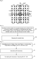
Fig. 4 is a schematic diagram of a basic implementation flow of a method for implementing a multi-stage encoding device according to an embodiment of the disclosure; -
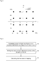
Fig. 5 is a schematic diagram of a constellation map of 64qam (0, 4) according to an embodiment of the disclosure; -
Fig. 6 is a schematic diagram of a basic flow of connecting an RS encoder and an LDPC encoder in parallel and mapping the encoded data according to an embodiment of the disclosure; -
Fig. 7 is a schematic diagram of a detailed implementation flow of connecting an RS encoder and an LDPC encoder in parallel and mapping the encoded data according to an embodiment of the disclosure; -
Fig. 8 is a schematic diagram of a constellation map of qpsk (0, 2) according to an embodiment of the disclosure; -
Fig. 9 is a schematic diagram of a constellation map of 64qam (4, 2) according to an embodiment of the disclosure; -
Fig. 10 is a schematic diagram of a basic implementation flow of another method for implementing a multi-stage encoding device according to an embodiment of the disclosure; and -
Fig. 11 is a schematic diagram of an implementation flow of connecting an RS encoder, a Convolution encoder and an LDPC encoder in parallel and mapping the encoded data according to an embodiment of the disclosure. - In an embodiment of the disclosure, an input selection switch and an output selection switch are provided between input and output ends of two encoders, and these two encoders are enabled to encode in parallel or in series by controlling the output selection switch and the input selection switch; or for multiple encoders, the input selection switch and the output selection switch are provided between the input end and the output end of every two neighboring encoders respectively, and the multiple encoders are enabled to encode in parallel or in series by controlling each output selection switch and each input selection switch.
- Here, the encoders include, but are not limited to, a RS encoder, a LDPC encoder, a convolution encoder and a Turbo encoder.
- As shown in
Fig. 1 , the composition structure of a multi-stage encoding device in an embodiment of the disclosure includes afirst encoder 10 and asecond encoder 20;
an input end of thefirst encoder 10 is connected to a data input end, an output end of thefirst encoder 10 is connected to a constellation map mapper via anoutput selection switch 11, and the output end of thefirst encoder 10 is connected to a first input end of aninput selection switch 21;
a second input end of theinput selection switch 21 is connected to the data input end, and an output end of theinput selection switch 21 is connected to an input end of thesecond encoder 20; an output end of thesecond encoder 20 is connected to aconstellation map mapper 30; and
an on/off state of theoutput selection switch 11 enables theinput selection switch 21 to switch on different input ends. - In an embodiment, when the
output selection switch 11 is in an on state, theinput selection switch 21 switches the second input end on, and thefirst encoder 10 and thesecond encoder 20 are connected in parallel. - In an embodiment, when the
output selection switch 11 is in an off state, theinput selection switch 21 switches the first input end on, and thefirst encoder 10 and thesecond encoder 20 are connected in series. - In an embodiment, the
first encoder 10 is the RS encoder, and thesecond encoder 20 is the LDPC encoder. - As shown in
Fig. 2 , the composition structure of another multi-stage encoding device in an embodiment of the disclosure includes afirst encoder 10, asecond encoder 20 and at least onethird encoder 40;
the input end of thefirst encoder 10 is connected to the data input end, the output end of thefirst encoder 10 is connected to theconstellation map mapper 30 via the firstoutput selection switch 31, and the output end of thefirst encoder 10 is connected to a first input end of a firstinput selection switch 41;
the second input end of the firstinput selection switch 41 is connected to the data input end, and the output end of the firstinput selection switch 41 is connected to an input end of thethird encoder 40 and a second input end of a secondinput selection switch 61; an output end of thethird encoder 40 is connected to theconstellation map mapper 30 via a secondoutput selection switch 51, and the output end of thethird encoder 40 is connected to a first input end of the secondinput selection switch 61;
a third input end of the secondinput selection switch 61 is connected to the data input end, an output end of the secondinput selection switch 61 is connected to an input end of thesecond encoder 20, and an output end of thesecond encoder 20 is connected to theconstellation map mapper 30;
an on/off state of the firstoutput selection switch 31, an on/off state of the secondoutput selection switch 51 and different input ends switched on by the firstinput selection switch 41 enable the secondinput selection switch 61 to switch on different input ends;
an on/off state of the secondoutput selection switch 51 and different input ends switched on by the firstinput selection switch 41 enable the secondinput selection switch 61 to switch on different input ends. - In an embodiment, when the first
output selection switch 31 is in the on state, the firstinput selection switch 41 switches the second input end on, the secondoutput selection switch 51 is in an on state, the secondinput selection switch 61 switches the third input end on, and thefirst encoder 10, thesecond encoder 20 and thethird encoder 40 are connected in parallel. - In an embodiment, when the first
output selection switch 31 is in the off state, the firstinput selection switch 41 switches the first input end on, the secondoutput selection switch 51 is in the on state, the secondinput selection switch 61 switches the third input end on, thefirst encoder 10 and thethird encoder 40 are connected in series with each other and are connected in parallel with thesecond encoder 20. - In an embodiment, when the first
output selection switch 31 is in the off state, the firstinput selection switch 41 switches the first input end on, the secondoutput selection switch 51 is in the off state, the secondinput selection switch 61 switches the first input end on, and thefirst encoder 10, thesecond encoder 20 and thethird encoder 40 are connected in series. - In an embodiment, when the first
output selection switch 31 is in the on state, the firstinput selection switch 41 switches the second input end on, the secondoutput selection switch 51 is in the off state, the secondinput selection switch 61 switches the first input end on, and thesecond encoder 20 and thethird encoder 40 are connected in series with each other and are connected in parallel with thefirst encoder 10. - In an embodiment, when the first
output selection switch 31 is in the off state, the firstinput selection switch 41 switches the first input end on, the secondoutput selection switch 51 is in the off state, the secondinput selection switch 61 switches the second input end on, and thefirst encoder 10 and thesecond encoder 20 are connected in series. - In an embodiment, when the first
output selection switch 31 is in the on state, the firstinput selection switch 41 switches the second input end on, the secondoutput selection switch 51 is in the off state, the secondinput selection switch 61 switches the third input end on, and thefirst encoder 10 and thesecond encoder 20 are connected in parallel. - In an embodiment, when the first
output selection switch 31 is in the off state, the firstinput selection switch 41 switches the second input end on, the secondoutput selection switch 51 is in the off state, the secondinput selection switch 61 switches the first input end on, and thesecond encoder 20 and thethird encoder 40 are connected in series. - In an embodiment, when the first
output selection switch 31 is in the off state, the firstinput selection switch 41 switches the second input end on, the secondoutput selection switch 51 is in the on state, the secondinput selection switch 61 switches the third input end on, and thesecond encoder 20 and thethird encoder 40 are connected in parallel. - In an embodiment, when the first
output selection switch 31 is in the off state, the firstinput selection switch 41 switches the first input end on, the secondoutput selection switch 51 is in the on state, the secondinput selection switch 61 switches the first input end or the second input end on, and thefirst encoder 10 and thethird encoder 40 are connected in series. - In an embodiment, when the first
output selection switch 31 is in the on state, the firstinput selection switch 41 switches the second input end on, the secondoutput selection switch 51 is in the on state, the secondinput selection switch 61 switches the first input end or the second input end on, and thefirst encoder 10 and thethird encoder 40 are connected in parallel. - In an embodiment, the third encoder includes a number of
third encoders 40, which is equal to N, an output end of each of thethird encoders 40 is connected to the constellation map mapper via one output selection switch, and an input end of each of thethird encoders 40 is connected to an output end of one input selection switch, where N is greater than 1; as shown inFig. 3 , the composition structure of yet another multi-stage encoding device of an embodiment of the disclosure includes afirst encoder 10, asecond encoder 20 and a number N ofthird encoders 40;
the input end of a first one of thethird encoders 401 is connected to the output end of the firstinput selection switch 41; the output end of the first one of thethird encoders 401 is connected to the first input end of the secondinput selection switch 61;
an input end of an ith one of the third encoders 40i is connected to an output end of an ith input selection switch, where i is greater than or equal to 2 and less than N; an output end of the ith one of the third encoders 40i is connected to a first input end of an (i+1)th input selection switch; a number of the input ends of the ith input selection switch is equal to i+1; an (i+1)th input end of the ith input selection switch is connected to the data input end; second to ith input ends of the ith input selection switch are connected with the output ends of the first input selection switch to an (i-1)th input selection switch respectively;
an output end of an Nth one of thethird encoders 40N is connected to the first input end of an (N+1)th input selection switch; a number of the input ends of the (N+1)th input selection switch is equal to N+2, and an (N+2)th input end of the (N+1)th input selection switch is connected to the data input end; second to (N+1)th input ends of the (N+1)th input selection switch are connected to the output ends of the first input selection switch to an Nth input selection switch respectively; an output end of the (N+1)th input selection switch is connected to the input end of thesecond encoder 20; wherein the Nth input end is expressed by N-1. - In an embodiment, the first encoder is the RS encoder, the second encoder is the LDPC encoder, and the third encoder is the Convolution encoder, the Turbo encoder, or multiple parity check code encoders other than the LDPC encoder.
- An embodiment of the disclosure further provides a method for implementing a multi-stage encoding device, in which an input selection switch and an output selection switch are provided between input and output ends of a first encoder and a second encoder; as shown in
Fig. 4 , the basic implementation flow of the method includes the following steps. - Step 101: the first encoder and the second encoder are enabled to encode in parallel or in series by controlling the output selection switch and the input selection switch;
specifically, when the output end of the first encoder is connected to the constellation map mapper by the output selection switch, and the input end of the second encoder is connected to the data input end by the input selection switch, the first encoder and the second encoder encode in parallel; that is, the data encoded by the first encoder enters the second encoder, and is output after being encoded by the second encoder;
when the output end of the output selection switch is connected to the input end of the input selection switch to enable the output end of the first encoder and the input end of the second encoder to be connected, the first encoder and the second encoder encode in parallel; that is, the data encoded by the first encoder and the data encoded by the second encoder are output separately;
the first encoder is the RS encoder, and the second encoder is the LDPC encoder. - Step 102: the encoded data is mapped;
when the first encoder and the second encoder encode in series, and the encoded data is mapped, there is only the mapping mode of the second encoding, that is, the constellation map is directly mapped; specifically, by taking that a modulation mode is 16qam and the data after the second encoding is 4'b1101 for example, the implementation process of mapping the encoded data is as follows: - in the constellation map of 64qam (0, 4) shown in
Fig. 5 , two high bits 2'b11 correspond to the bit b3b2 at the lower right corner ofFig. 5 , and the bit b3b2 corresponds to four constellation points in the first column on the left ofFig. 4 ; two low bits 2'b01 correspond to the bit b1b0 at the upper left corner ofFig. 4 , and the bit b1b0 corresponds to four constellation points in the first line on the top ofFig. 5 ; the intersection point of the first column on the left and the first line on the top is the value obtained after mapping the data 4'b1101; the coordinate value of I axis corresponding to the intersection point is -3, and the coordinate value of Q axis corresponding to the intersection point is 3; the modulated symbol of the data 4'b1101 is (-3, 3). - When the first encoder and the second encoder are connected in parallel and the encoded data is mapped, it is necessary to first map the data after the first encoding and the second encoding respectively, calculate two different mapping results, and finally calculate a corresponding point in the constellation map;
specifically, for the quadrature amplitude (2MQAM) modulation mode, each constellation point contains M bits, assuming that M=X+Y. There are totally 2M constellation points in the constellation map, the 2M constellation points are divided into 2Y constellation point subsets, and each subset contains 2X constellation points. For each constellation point, Y bits in the M bits data are filled with information bit data after the LDPC encoding, at the same time the Y bits can also be used for identifying a constellation point subset, and this portion of bits are also called a subset index; the rest X bits are filled with RS information bit data not encoded, at the same time the X bits can also be used for identifying a certain constellation point in the subset. Although the bit data not encoded is not protected by encoding, the distance between the constellation points in the subset can become very large by providing the constellation map, so the noise resisting capability of the bit data not encoded is enhanced. QAMY represents a corresponding constellation map mapping table when the Y bits after the LDPC encoding are modulated, and QAMX represents a corresponding constellation map mapping table when the X bits after the RS encoding are modulated. - As shown in
Fig. 6 , the basic flow that the first encoder and the second encoder are connected in parallel and the encoded data is mapped includes the following steps. -
Step 2a: values of 2xqam and 2yqam in a full encoding are calculated respectively according to x and y bits;
specifically, the structure in a full encoding can be multiplexed; for example, the values of 16qam and Quadrature Phase Shift Keying (QPSK) modulation under the LDPC encoding can be calculated respectively with 64qam(4, 2). -
Step 2b: the value of 2Xqam obtained according to x bits is shifted to the left;
specifically, the number of bits shifted to the left is y/2, wherein y is an even number; when the value is shifted to the left, the right vacancy is filled with zero to obtain a shift amount of a value of a basic unit. - Step 2c: the final value of mapping is calculated;
specifically, the obtained shift amount and the value of 2yqam obtained according to y bits are added to obtain the final value of mapping. - By taking that the RS encoder and the LDPC encoder are connected in parallel, the modulation mode is 64qam (4, 2), and the encoded data is 6'b110110 for example, if x=4'1101 and y=2'10, as shown in
Fig. 7 , the detailed implementation flow of mapping the encoded data includes the following steps. -
Step 3a: values of 2xqam and 2yqam in a full encoding are calculated respectively according to 4'1101 and 2'10;
specifically, according to the calculation ofStep 102, the value in the constellation map inFig. 4 corresponding to x=4'b1101 is (-3, 3), and the value in the constellation map of qpsk (0, 2) inFig. 7 corresponding to y=2'b10 is (-1, 1). -
Step 3b: the shift amount is calculated;
specifically, y is 2 bits, and y/2=1; so the value obtained according to x=4'1101 is shifted by one bit to the left, which is equivalent to multiplying the value by 2, that is, -3x2=-6, and 3x2=6; so the calculated shift amounts are -6 and 6. - Step 3c: the final value of mapping 6'b110110 is calculated;
specifically, the shift amounts -6 and 6 are added to the value (-1, 1) in the constellation map of qpsk (0, 2) inFig. 8 corresponding to 2'b10 respectively, so as to obtain a constellation point coordinate (-7, 7) of the data 6'b110110, namely the modulated symbol of the data 6'b110110 is (-7, 7). - It can be seen that for multi-stage encoding, the basic unit of the constellation map is the constellation map corresponding to y, and the units of y are arranged to different positions according to x;
Fig. 9 is the constellation map of 64qam (4, 2) whose basic unit is qpsk (0, 2) inFig. 7 ; the point connected by a solid line inFig. 8 is the original position of qpsk (0, 2), and the units at different positions are shifts from the original position of qpsk (0, 2); a shift value is decided by x in (x, y), and is equal to the index*2(y/2) in a full encoding corresponding to x. - An embodiment of the disclosure further provides another method for implementing a multi-stage encoding device, in which a first output selection switch and a first input selection switch are provided between input and output ends of a first encoder and a third encoder; a second output selection switch and a second input selection switch are provided between input and output ends of the third encoder and a second encoder; as shown in
Fig. 10 , the basic implementation flow of the method includes the following steps. - Step 201: the first encoder, the second encoder and the third encoder are enabled to encode in series or in parallel by controlling the first output selection switch, the first input selection switch, the second output selection switch and the second input selection switch;
the third encoder includes a number of third encoders, which is equal to N, an output end of each of the third encoders is connected to the constellation map mapper via one output selection switch, and an input end of each of the third encoders is connected to an output end of one input selection switch, where N is greater than 1,;
the first encoder, the second encoder and the number N of third encoders are enabled to encode in parallel or in series by controlling each input selection switch and each output selection switch;
here, the first encoder is the RS encoder, the second encoder is the LDPC encoder, and the third encoder is the Convolution encoder, the Turbo encoder, or multiple parity check code encoders other than the LDPC encoder. - Step 202: the encoded data is mapped;
specifically, when the encoded data is output in series and the encoded data is mapped, there is only the mapping mode of the LDPC encoding, that is, the constellation map is directly mapped; when the encoded data is output in parallel and the encoded data is mapped, it is necessary to first map the data encoded by each encoder respectively, calculate all the mapping results, and finally calculate corresponding points in the constellation map. - By taking that the RS encoder, the Convolution encoder and the LDPC encoder are connected in parallel, the modulation mode is 256qam (4, 2, 2) and the data is 8'b11011001 for example, if x=4'b1101, y=2'b10 and z=2'b01, as shown in
Fig. 11 , the implementation flow of mapping the encoded data includes the following steps. -
Step 4a: values of 2xqam, 2yqam and 2zqam in a full encoding are calculated respectively according to 4'b1101, 2'b10 and 2'b01;
specifically, according to the calculation ofStep 102, the value in the constellation map inFig. 4 corresponding to x=4'b1101 is (-3, 3), the value in qpsk (0, 2) inFig. 7 corresponding to y=2'b10 is (-1, 1), and the value in qpsk (0, 2) inFig. 7 corresponding to z=2'b01 is (-1, 1). -
Step 4b: the shift amount is calculated;
specifically, the first shift amounts -6 and 6 are obtained by performing the same processing as that in Step b on the values obtained by mapping x and y;
z is 2 bits, and z/2=1; so, shifting by one bit to the left is equivalent to multiplying the first shift amounts by 2, that is, -6x2=-12, and 6x2=12; so the calculated shift amounts are -12 and 12. - Step 4c: the final value of mapping 8'b11011001 is calculated;
specifically, the shift amounts -12 and 12 are added to the value (-1, 1) in qpsk (0, 2) inFig. 7 corresponding to 2'b01 respectively, so as to obtain a constellation point coordinate (-13, 13) of the data 8'b11011001. - Note that the multi-stage encoding device includes N third encoders, if N is greater than or equal to 2, the same recursion mode as recited in
Step 4c would be adopted to perform the modulation. - It can be seen that the method for implementing a multi-stage encoding modulation device provided by an embodiment of the disclosure supports a full encoding modulation mode and a parallel encoding modulation mode; in the full encoding modulation mode, the data entering the constellation map mapper is the data after the LDPC encoding, and the modulation mode includes 11 full encoding modulation modes from qpsk to 4096QAM; in the parallel encoding modulation mode, a part of the data entering the constellation map mapper is the data after multiple encoding modes, and other than the 11 full encoding modulation modes from qpsk to 4096QAM, part encoding modulation modes of the 11 full encoding modulation modes are also included, such as qpsk (1, 1), 16qam (2, 2), 32qam (3, 2), 32qam (2, 3), 64qam (4, 2), 64QAM (2, 4), 4096qam (10, 2), 4096qam (2, 10); so the modulation mode is flexible. At the same time, the multi-stage encoding device of an embodiment of the disclosure has a simple structure, reduces the design complexity by multiplexing circuits in different modulation modes, and reduces hardware resources; besides, the output mapping symbol rate can be matched to the extent that a full-rate output can be supported, so the demand of a high-throughput scenario can be met.
- In the embodiment of the disclosure, if the message transmission method is implemented in a form of software function modules, and the software function modules are sold or used as independent products, they can also be stored in a computer readable storage medium. Based on this understanding, the technical solutions of the embodiments of the disclosure in the nature or with the part making a contribution to the prior art can be embodied in the form of a software product; the computer software product is stored in a storage medium and includes a number of instructions to cause a computer device (which may be a personal computer, a server or a network device, etc.) perform all or part of the method in each of the embodiments of the disclosure. The above-described storage medium includes a USB flash disk, a mobile hard disk, a Read Only Memory (ROM), a magnetic disk or a compact disc, and various other media which can store program codes. In this way, the embodiment of the disclosure is not limited to any particular combination of hardware and software.
- Correspondingly, an embodiment of the disclosure further provides a computer storage medium in which a computer program is stored, the computer program is used for performing the above methods for implementing the multi-stage encoding device according to the embodiment of the disclosure.
- What are described above are only the preferred embodiments of the disclosure and not intended to limit the scope of protection of the disclosure.
Claims (25)
- A multi-stage encoding device comprising a first encoder and a second encoder, wherein an input end of the first encoder is connected to a data input end, an output end of the first encoder is connected to a constellation mapper via an output selection switch, and the output end of the first encoder is connected to a first input end of an input selection switch,
wherein a second input end of the input selection switch is connected to the data input end, and an output end of the input selection switch is connected to an input end of the second encoder; an output end of the second encoder is connected to the constellation mapper, and
wherein an on/off state of the output selection switch enables the input selection switch to switch on different input ends. - The multi-stage encoding device according to claim 1, wherein when the output selection switch is in the on state, the input selection switch switches the second input end on, and the first encoder and the second encoder are connected in parallel.
- The multi-stage encoding device according to claim 1, wherein when the output selection switch is in the off state, the input selection switch switches the first input end on, and the first encoder and the second encoder are connected in series.
- The multi-stage encoding device according to any one of claims 1 to 3, wherein the first encoder is a Reed-Solomon, RS, encoder, and the second encoder is a Low Density Parity Check Code, LDPC, encoder.
- A multi-stage encoding device comprising a first encoder, a second encoder and at least one third encoder,
wherein an input end of the first encoder is connected to a data input end, an output end of the first encoder is connected to a constellation mapper via a first output selection switch, and the output end of the first encoder is connected to a first input end of a first input selection switch,
wherein a second input end of the first input selection switch is connected to the data input end, and an output end of the first input selection switch is connected to an input end of the third encoder and a second input end of a second input selection switch; an output end of the third encoder is connected to the constellation mapper via a second output selection switch, and the output end of the third encoder is connected to a first input end of the second input selection switch,
wherein a third input end of the second input selection switch is connected to the data input end, an output end of the second input selection switch is connected to an input end of the second encoder, and an output end of the second encoder is connected to the constellation mapper, and
an on/off state of the first output selection switch, an on/off state of the second output selection switch, and different input ends switched on by the first input selection switch enable the second input selection switch to switch on different input ends. - The multi-stage encoding device according to claim 5, wherein when the first output selection switch is in the on state, the first input selection switch switches the second input end on, the second output selection switch is in the on state, the second input selection switch switches the third input end on, and the first encoder, the second encoder and the third encoder are connected in parallel.
- The multi-stage encoding device according to claim 5, wherein when the first output selection switch is in the off state, the first input selection switch switches the first input end on, the second output selection switch is in the on state, the second input selection switch switches the third input end on, and the first encoder and the third encoder are connected in series with each other and are connected in parallel with the second encoder.
- The multi-stage encoding device according to claim 5, wherein when the first output selection switch is in the off state, the first input selection switch switches the first input end on, the second output selection switch is in the off state, the second input selection switch switches the first input end on, and the first encoder, the second encoder and the third encoder are connected in series.
- The multi-stage encoding device according to claim 5, wherein when the first output selection switch is in the on state, the first input selection switch switches the second input end on, the second output selection switch is in the off state, the second input selection switch switches the first input end on, and the second encoder and the third encoder are connected in series with each other and are connected in parallel with the first encoder.
- The multi-stage encoding device according to claim 5, wherein when the first output selection switch is in the off state, the first input selection switch switches the first input end on, the second output selection switch is in the off state, the second input selection switch switches the second input end on, and the first encoder and the second encoder are connected in series.
- The multi-stage encoding device according to claim 5, wherein when the first output selection switch is in the on state, the first input selection switch switches the second input end on, the second output selection switch is in the off state, the second input selection switch switches the third input end on, and the first encoder and the second encoder are connected in parallel.
- The multi-stage encoding device according to claim 5, wherein when the first output selection switch is in the off state, the first input selection switch switches the second input end on, the second output selection switch is in the off state, the second input selection switch switches the first input end on, and the second encoder and the third encoder are connected in series.
- The multi-stage encoding device according to claim 5, wherein when the first output selection switch is in the off state, the first input selection switch switches the second input end on, the second output selection switch is in the on state, the second input selection switch switches the third input end on, and the second encoder and the third encoder are connected in parallel.
- The multi-stage encoding device according to claim 5, wherein when the first output selection switch is in the off state, the first input selection switch switches the first input end on, the second output selection switch is in the on state, the second input selection switch switches the first input end or the second input end on, and the first encoder and the third encoder are connected in series.
- The multi-stage encoding device according to claim 5, wherein when the first output selection switch is in the on state, the first input selection switch switches the second input end on, the second output selection switch is in the on state, the second input selection switch switches the first input end or the second input end on, and the first encoder and the third encoder are connected in parallel.
- The multi-stage encoding device according to claim 5, wherein the third encoder includes a number of third encoders, which is equal to N, for each of the third encoders, an output end of said third encoder is connected to the constellation mapper via a respective output selection switch, and an input end of said third encoder is connected to an output end of a respective input selection switch, wherein N is greater than 1;
an input end of a first one of the third encoders is connected to the output end of the first input selection switch, and an output end of the first one of the third encoders is connected to the first input end of the second input selection switch;
an input end of an ith one of the third encoders is connected to an output end of an ith input selection switch, wherein i is greater than or equal to 2 and less than N; an output end of the ith one of the third encoders is connected to a first input end of an (i+1)th input selection switch; a number of the input ends of the ith input selection switch is equal to i+1, an (i+1)th input end of the ith input selection switch is connected to the data input end; second to ith input ends of the ith input selection switch are connected with output ends of the first input selection switch to an (i-1)th input selection switch respectively; and
an output end of an Nth one of the third encoders is connected to a first input end of an (N+1)th input selection switch; a number of the input ends of the (N+1)th input selection switch is equal to N+2, and an (N+2)th input end of the (N+1)th input selection switch is connected to the data input end; second to (N+1)th input ends of the (N+1)th input selection switch are connected to output ends of the first to Nth input selection switches respectively; an output end of the (N+1)th input selection switch is connected to the input end of the second encoder. - The multi-stage encoding device according to any one of claims 5 to 16, wherein the first encoder is a Reed-Solomon, RS, encoder, the second encoder is a Low Density Parity Check Code, LDPC, encoder, and the third encoder is a convolution encoder or a Turbo encoder.
- A method for implementing a multi-stage encoding device, wherein the method comprises:providing an input selection switch and an output selection switch between input and output ends of first and second encoders; andenabling the first encoder and the second encoder to encode in parallel or in series by controlling the output selection switch and the input selection switch.
- The method for implementing the multi-stage encoding device according to claim 18, wherein the first encoder and the second encoder are enabled to encode in parallel, when the output end of the first encoder and a constellation mapper are connected by the output selection switch and the input end of the second encoder and a data input end are connected by the input selection switch.
- The method for implementing the multi-stage encoding device according to claim 18, wherein the first encoder and the second encoder are enabled to encode in series, when an output end of the output selection switch is connected to an input end of the input selection switch to enable the output end of the first encoder and the input end of the second encoder to be connected.
- The method for implementing the multi-stage encoding device according to claim 18, 19 or 20, wherein the first encoder is a Reed-Solomon, RS, encoder, and the second encoder is a Low Density Parity Check Code, LDPC, encoder.
- A method for implementing a multi-stage encoding device, wherein the method comprises:providing a first output selection switch and a first input selection switch between an input end and an output end of a first encoder and a third encoder;providing a second output selection switch and a second input selection switch between an input end and an output end of the third encoder and a second encoder; andenabling the first encoder, the second encoder and the third encoder to encode in series or in parallel by controlling the first output selection switch, the first input selection switch, the second output selection switch and the second input selection switch.
- The method for implementing the multi-stage encoding device according to claim 22, wherein the third encoder includes a number of third encoders, which is equal to N, an output end of each of the third encoders is connected to a constellation mapper via a respective output selection switch, and an input end of each of the third encoders is connected to an output end of a respective input selection switch, wherein N is greater than 1; and
wherein said enabling comprises:enabling the first encoder, the second encoder and the N third encoders to encode in parallel or in series by controlling each input selection switch and each output selection switch. - The method for implementing the multi-stage encoding device according to claim 22 or 23, wherein the first encoder is a Reed-Solomon, RS, encoder, the second encoder is a Low Density Parity Check Code, LDPC, encoder, and the third encoder is a convolution encoder or a Turbo encoder.
- A computer storage medium in which a computer executable instruction is stored for performing the method for implementing the multi-stage encoding device according to any one of claims 18 to 21, or for performing the method for implementing the multi-stage encoding device according to any one of claims 22 to 24.
Applications Claiming Priority (2)
| Application Number | Priority Date | Filing Date | Title |
|---|---|---|---|
| CN201410298875.4A CN105262558B (en) | 2014-06-26 | 2014-06-26 | A kind of multilevel coding device and its implementation |
| PCT/CN2014/085991 WO2015196565A1 (en) | 2014-06-26 | 2014-09-05 | Multi-stage encoding device, method for implementing multi-stage encoding device and storage medium |
Publications (3)
| Publication Number | Publication Date |
|---|---|
| EP3160070A1 true EP3160070A1 (en) | 2017-04-26 |
| EP3160070A4 EP3160070A4 (en) | 2017-07-05 |
| EP3160070B1 EP3160070B1 (en) | 2021-05-19 |
Family
ID=54936565
Family Applications (1)
| Application Number | Title | Priority Date | Filing Date |
|---|---|---|---|
| EP14896157.6A Active EP3160070B1 (en) | 2014-06-26 | 2014-09-05 | Multi-stage encoding device, method for implementing multi-stage encoding device and storage medium |
Country Status (3)
| Country | Link |
|---|---|
| EP (1) | EP3160070B1 (en) |
| CN (1) | CN105262558B (en) |
| WO (1) | WO2015196565A1 (en) |
Families Citing this family (1)
| Publication number | Priority date | Publication date | Assignee | Title |
|---|---|---|---|---|
| CN107800511B (en) * | 2016-09-05 | 2021-11-12 | 中兴通讯股份有限公司 | Mapping method and device for multi-level coding modulation system |
Family Cites Families (14)
| Publication number | Priority date | Publication date | Assignee | Title |
|---|---|---|---|---|
| US5734962A (en) * | 1996-07-17 | 1998-03-31 | General Electric Company | Satellite communications system utilizing parallel concatenated coding |
| JP3759964B2 (en) * | 1997-06-13 | 2006-03-29 | ルーセント テクノロジーズ インコーポレーテッド | Multi-level coding using time diversity |
| US6437714B1 (en) * | 1998-04-18 | 2002-08-20 | Samsung Electronics, Co., Ltd. | Channel encoding device and method for communication system |
| US20020150167A1 (en) * | 2001-02-17 | 2002-10-17 | Victor Demjanenko | Methods and apparatus for configurable or assymetric forward error correction |
| CN1151677C (en) * | 2001-08-17 | 2004-05-26 | 清华大学 | cascaded error correction coder |
| US20030101407A1 (en) * | 2001-11-09 | 2003-05-29 | Cute Ltd. | Selectable complexity turbo coding system |
| KR20030097358A (en) * | 2002-06-20 | 2003-12-31 | 삼성전자주식회사 | Method for coding of signal using convolutional encoder and turbo coder based on puncturing pattern determined according to constellation |
| CN1849765B (en) * | 2003-09-09 | 2011-04-27 | 株式会社Ntt都科摩 | Signal transmission method, transmitter and receiver in wireless multiple transmission system |
| KR100723479B1 (en) * | 2004-12-04 | 2007-05-31 | 삼성전자주식회사 | Decision-feedback equalizer of digital television receiver and its method |
| CN100586028C (en) * | 2006-08-09 | 2010-01-27 | 华为技术有限公司 | Method and device for realizing LDPC coding |
| US8719670B1 (en) * | 2008-05-07 | 2014-05-06 | Sk Hynix Memory Solutions Inc. | Coding architecture for multi-level NAND flash memory with stuck cells |
| EP2282471A1 (en) * | 2009-08-07 | 2011-02-09 | Thomson Licensing | Data transmission using low density parity check coding and constellation mapping |
| CN102588751A (en) * | 2011-01-05 | 2012-07-18 | 晶元光电股份有限公司 | light emitting device |
| US9203673B2 (en) * | 2012-05-13 | 2015-12-01 | Broadcom Corporation | Multi-channel support within single user, multiple user, multiple access, and/or MIMO wireless communications |
-
2014
- 2014-06-26 CN CN201410298875.4A patent/CN105262558B/en active Active
- 2014-09-05 WO PCT/CN2014/085991 patent/WO2015196565A1/en not_active Ceased
- 2014-09-05 EP EP14896157.6A patent/EP3160070B1/en active Active
Also Published As
| Publication number | Publication date |
|---|---|
| CN105262558B (en) | 2019-07-09 |
| WO2015196565A1 (en) | 2015-12-30 |
| EP3160070B1 (en) | 2021-05-19 |
| CN105262558A (en) | 2016-01-20 |
| EP3160070A4 (en) | 2017-07-05 |
Similar Documents
| Publication | Publication Date | Title |
|---|---|---|
| JP4094809B2 (en) | Time variable lattice code | |
| CN101710850B (en) | Convolution Turbo encoding method and device for realizing encoding method | |
| WO2007108471A1 (en) | Modulation device, demodulation device, and modulating method | |
| US8875000B2 (en) | Methods and systems systems for encoding and decoding in trellis coded modulation systems | |
| CN109155634A (en) | Implement the device and method of polarization code | |
| CN103580807A (en) | BICM transmission method and system for LDPC code words in specific degree distribution | |
| KR20240024869A (en) | Apparatus of inverse zero padding for variable-length signaling information and method using the same | |
| CN103516661B (en) | A kind of high order modulation approach, de-mapping method and related device | |
| KR20220113322A (en) | Bicm reception device and method corresponding to 16-symbol mapping and low density parity check codeword with 16200 length, 3/15 rate | |
| KR102080607B1 (en) | Apparatus and method for modulation and demodulation of nonbinary channel coding in broadcasting and communication systems | |
| CN105959082B (en) | Joint coding and modulation method and device based on multi-ary coding and high-order modulation | |
| Abdelaziz et al. | Ternary convolutional codes for ternary phase shift keying | |
| US20240039558A1 (en) | Radio Transmitter and Receiver | |
| EP3160070B1 (en) | Multi-stage encoding device, method for implementing multi-stage encoding device and storage medium | |
| CN112398580B (en) | A modulation method and device | |
| KR100963463B1 (en) | Improved Turbo Code Interleaver for Low Frame Error Rate | |
| CN107786300B (en) | Data sending method and device | |
| KR102159242B1 (en) | Transmitter and signal processing method thereof | |
| KR100912600B1 (en) | Tail-biting turbo code for arbitrary number of information bits | |
| KR100653232B1 (en) | JAM symbol mapping method and apparatus for cable downstream transmission | |
| CN111181572B (en) | Interleaving mapping method and de-interleaving de-mapping method for LDPC code word | |
| CN105337691A (en) | LDPC codeword interleaving and mapping method and LDPC codeword de-interleaving and de-mapping method | |
| US8095845B1 (en) | System and method for assigning code blocks to constituent decoder units in a turbo decoding system having parallel decoding units | |
| Li et al. | Low-rate repeat-zigzag-Hadamard codes | |
| JP2006173724A (en) | Decoding method and decoding apparatus in trellis or turbo trellis coded modulation system |
Legal Events
| Date | Code | Title | Description |
|---|---|---|---|
| STAA | Information on the status of an ep patent application or granted ep patent |
Free format text: STATUS: THE INTERNATIONAL PUBLICATION HAS BEEN MADE |
|
| PUAI | Public reference made under article 153(3) epc to a published international application that has entered the european phase |
Free format text: ORIGINAL CODE: 0009012 |
|
| STAA | Information on the status of an ep patent application or granted ep patent |
Free format text: STATUS: REQUEST FOR EXAMINATION WAS MADE |
|
| 17P | Request for examination filed |
Effective date: 20170123 |
|
| AK | Designated contracting states |
Kind code of ref document: A1 Designated state(s): AL AT BE BG CH CY CZ DE DK EE ES FI FR GB GR HR HU IE IS IT LI LT LU LV MC MK MT NL NO PL PT RO RS SE SI SK SM TR |
|
| AX | Request for extension of the european patent |
Extension state: BA ME |
|
| A4 | Supplementary search report drawn up and despatched |
Effective date: 20170607 |
|
| RIC1 | Information provided on ipc code assigned before grant |
Ipc: H03M 13/29 20060101ALI20170531BHEP Ipc: H03M 13/11 20060101ALN20170531BHEP Ipc: H03M 13/15 20060101ALN20170531BHEP Ipc: H04L 1/00 20060101AFI20170531BHEP Ipc: H03M 13/35 20060101ALI20170531BHEP Ipc: H03M 13/23 20060101ALN20170531BHEP Ipc: H03M 13/25 20060101ALI20170531BHEP |
|
| DAX | Request for extension of the european patent (deleted) | ||
| STAA | Information on the status of an ep patent application or granted ep patent |
Free format text: STATUS: EXAMINATION IS IN PROGRESS |
|
| 17Q | First examination report despatched |
Effective date: 20190509 |
|
| RIC1 | Information provided on ipc code assigned before grant |
Ipc: H04L 1/00 20060101AFI20201202BHEP Ipc: H03M 13/11 20060101ALN20201202BHEP Ipc: H03M 13/23 20060101ALN20201202BHEP Ipc: H03M 13/29 20060101ALI20201202BHEP Ipc: H03M 13/25 20060101ALI20201202BHEP Ipc: H03M 13/35 20060101ALI20201202BHEP Ipc: H03M 13/15 20060101ALN20201202BHEP |
|
| GRAP | Despatch of communication of intention to grant a patent |
Free format text: ORIGINAL CODE: EPIDOSNIGR1 |
|
| STAA | Information on the status of an ep patent application or granted ep patent |
Free format text: STATUS: GRANT OF PATENT IS INTENDED |
|
| INTG | Intention to grant announced |
Effective date: 20210112 |
|
| GRAS | Grant fee paid |
Free format text: ORIGINAL CODE: EPIDOSNIGR3 |
|
| GRAA | (expected) grant |
Free format text: ORIGINAL CODE: 0009210 |
|
| STAA | Information on the status of an ep patent application or granted ep patent |
Free format text: STATUS: THE PATENT HAS BEEN GRANTED |
|
| AK | Designated contracting states |
Kind code of ref document: B1 Designated state(s): AL AT BE BG CH CY CZ DE DK EE ES FI FR GB GR HR HU IE IS IT LI LT LU LV MC MK MT NL NO PL PT RO RS SE SI SK SM TR |
|
| REG | Reference to a national code |
Ref country code: GB Ref legal event code: FG4D |
|
| REG | Reference to a national code |
Ref country code: CH Ref legal event code: EP |
|
| REG | Reference to a national code |
Ref country code: DE Ref legal event code: R096 Ref document number: 602014077625 Country of ref document: DE |
|
| REG | Reference to a national code |
Ref country code: AT Ref legal event code: REF Ref document number: 1395025 Country of ref document: AT Kind code of ref document: T Effective date: 20210615 |
|
| REG | Reference to a national code |
Ref country code: IE Ref legal event code: FG4D |
|
| REG | Reference to a national code |
Ref country code: LT Ref legal event code: MG9D |
|
| REG | Reference to a national code |
Ref country code: AT Ref legal event code: MK05 Ref document number: 1395025 Country of ref document: AT Kind code of ref document: T Effective date: 20210519 |
|
| REG | Reference to a national code |
Ref country code: NL Ref legal event code: MP Effective date: 20210519 |
|
| PG25 | Lapsed in a contracting state [announced via postgrant information from national office to epo] |
Ref country code: HR Free format text: LAPSE BECAUSE OF FAILURE TO SUBMIT A TRANSLATION OF THE DESCRIPTION OR TO PAY THE FEE WITHIN THE PRESCRIBED TIME-LIMIT Effective date: 20210519 Ref country code: FI Free format text: LAPSE BECAUSE OF FAILURE TO SUBMIT A TRANSLATION OF THE DESCRIPTION OR TO PAY THE FEE WITHIN THE PRESCRIBED TIME-LIMIT Effective date: 20210519 Ref country code: LT Free format text: LAPSE BECAUSE OF FAILURE TO SUBMIT A TRANSLATION OF THE DESCRIPTION OR TO PAY THE FEE WITHIN THE PRESCRIBED TIME-LIMIT Effective date: 20210519 Ref country code: BG Free format text: LAPSE BECAUSE OF FAILURE TO SUBMIT A TRANSLATION OF THE DESCRIPTION OR TO PAY THE FEE WITHIN THE PRESCRIBED TIME-LIMIT Effective date: 20210819 Ref country code: AT Free format text: LAPSE BECAUSE OF FAILURE TO SUBMIT A TRANSLATION OF THE DESCRIPTION OR TO PAY THE FEE WITHIN THE PRESCRIBED TIME-LIMIT Effective date: 20210519 |
|
| PG25 | Lapsed in a contracting state [announced via postgrant information from national office to epo] |
Ref country code: IS Free format text: LAPSE BECAUSE OF FAILURE TO SUBMIT A TRANSLATION OF THE DESCRIPTION OR TO PAY THE FEE WITHIN THE PRESCRIBED TIME-LIMIT Effective date: 20210919 Ref country code: GR Free format text: LAPSE BECAUSE OF FAILURE TO SUBMIT A TRANSLATION OF THE DESCRIPTION OR TO PAY THE FEE WITHIN THE PRESCRIBED TIME-LIMIT Effective date: 20210820 Ref country code: LV Free format text: LAPSE BECAUSE OF FAILURE TO SUBMIT A TRANSLATION OF THE DESCRIPTION OR TO PAY THE FEE WITHIN THE PRESCRIBED TIME-LIMIT Effective date: 20210519 Ref country code: ES Free format text: LAPSE BECAUSE OF FAILURE TO SUBMIT A TRANSLATION OF THE DESCRIPTION OR TO PAY THE FEE WITHIN THE PRESCRIBED TIME-LIMIT Effective date: 20210519 Ref country code: NO Free format text: LAPSE BECAUSE OF FAILURE TO SUBMIT A TRANSLATION OF THE DESCRIPTION OR TO PAY THE FEE WITHIN THE PRESCRIBED TIME-LIMIT Effective date: 20210819 Ref country code: PT Free format text: LAPSE BECAUSE OF FAILURE TO SUBMIT A TRANSLATION OF THE DESCRIPTION OR TO PAY THE FEE WITHIN THE PRESCRIBED TIME-LIMIT Effective date: 20210920 Ref country code: PL Free format text: LAPSE BECAUSE OF FAILURE TO SUBMIT A TRANSLATION OF THE DESCRIPTION OR TO PAY THE FEE WITHIN THE PRESCRIBED TIME-LIMIT Effective date: 20210519 Ref country code: SE Free format text: LAPSE BECAUSE OF FAILURE TO SUBMIT A TRANSLATION OF THE DESCRIPTION OR TO PAY THE FEE WITHIN THE PRESCRIBED TIME-LIMIT Effective date: 20210519 Ref country code: RS Free format text: LAPSE BECAUSE OF FAILURE TO SUBMIT A TRANSLATION OF THE DESCRIPTION OR TO PAY THE FEE WITHIN THE PRESCRIBED TIME-LIMIT Effective date: 20210519 |
|
| PG25 | Lapsed in a contracting state [announced via postgrant information from national office to epo] |
Ref country code: NL Free format text: LAPSE BECAUSE OF FAILURE TO SUBMIT A TRANSLATION OF THE DESCRIPTION OR TO PAY THE FEE WITHIN THE PRESCRIBED TIME-LIMIT Effective date: 20210519 |
|
| PG25 | Lapsed in a contracting state [announced via postgrant information from national office to epo] |
Ref country code: RO Free format text: LAPSE BECAUSE OF FAILURE TO SUBMIT A TRANSLATION OF THE DESCRIPTION OR TO PAY THE FEE WITHIN THE PRESCRIBED TIME-LIMIT Effective date: 20210519 Ref country code: SK Free format text: LAPSE BECAUSE OF FAILURE TO SUBMIT A TRANSLATION OF THE DESCRIPTION OR TO PAY THE FEE WITHIN THE PRESCRIBED TIME-LIMIT Effective date: 20210519 Ref country code: SM Free format text: LAPSE BECAUSE OF FAILURE TO SUBMIT A TRANSLATION OF THE DESCRIPTION OR TO PAY THE FEE WITHIN THE PRESCRIBED TIME-LIMIT Effective date: 20210519 Ref country code: EE Free format text: LAPSE BECAUSE OF FAILURE TO SUBMIT A TRANSLATION OF THE DESCRIPTION OR TO PAY THE FEE WITHIN THE PRESCRIBED TIME-LIMIT Effective date: 20210519 Ref country code: CZ Free format text: LAPSE BECAUSE OF FAILURE TO SUBMIT A TRANSLATION OF THE DESCRIPTION OR TO PAY THE FEE WITHIN THE PRESCRIBED TIME-LIMIT Effective date: 20210519 Ref country code: DK Free format text: LAPSE BECAUSE OF FAILURE TO SUBMIT A TRANSLATION OF THE DESCRIPTION OR TO PAY THE FEE WITHIN THE PRESCRIBED TIME-LIMIT Effective date: 20210519 |
|
| REG | Reference to a national code |
Ref country code: DE Ref legal event code: R097 Ref document number: 602014077625 Country of ref document: DE |
|
| PLBE | No opposition filed within time limit |
Free format text: ORIGINAL CODE: 0009261 |
|
| STAA | Information on the status of an ep patent application or granted ep patent |
Free format text: STATUS: NO OPPOSITION FILED WITHIN TIME LIMIT |
|
| 26N | No opposition filed |
Effective date: 20220222 |
|
| REG | Reference to a national code |
Ref country code: BE Ref legal event code: MM Effective date: 20210930 |
|
| PG25 | Lapsed in a contracting state [announced via postgrant information from national office to epo] |
Ref country code: IS Free format text: LAPSE BECAUSE OF FAILURE TO SUBMIT A TRANSLATION OF THE DESCRIPTION OR TO PAY THE FEE WITHIN THE PRESCRIBED TIME-LIMIT Effective date: 20210919 Ref country code: MC Free format text: LAPSE BECAUSE OF FAILURE TO SUBMIT A TRANSLATION OF THE DESCRIPTION OR TO PAY THE FEE WITHIN THE PRESCRIBED TIME-LIMIT Effective date: 20210519 Ref country code: AL Free format text: LAPSE BECAUSE OF FAILURE TO SUBMIT A TRANSLATION OF THE DESCRIPTION OR TO PAY THE FEE WITHIN THE PRESCRIBED TIME-LIMIT Effective date: 20210519 |
|
| PG25 | Lapsed in a contracting state [announced via postgrant information from national office to epo] |
Ref country code: LU Free format text: LAPSE BECAUSE OF NON-PAYMENT OF DUE FEES Effective date: 20210905 Ref country code: IT Free format text: LAPSE BECAUSE OF FAILURE TO SUBMIT A TRANSLATION OF THE DESCRIPTION OR TO PAY THE FEE WITHIN THE PRESCRIBED TIME-LIMIT Effective date: 20210519 Ref country code: IE Free format text: LAPSE BECAUSE OF NON-PAYMENT OF DUE FEES Effective date: 20210905 Ref country code: BE Free format text: LAPSE BECAUSE OF NON-PAYMENT OF DUE FEES Effective date: 20210930 |
|
| PG25 | Lapsed in a contracting state [announced via postgrant information from national office to epo] |
Ref country code: HU Free format text: LAPSE BECAUSE OF FAILURE TO SUBMIT A TRANSLATION OF THE DESCRIPTION OR TO PAY THE FEE WITHIN THE PRESCRIBED TIME-LIMIT; INVALID AB INITIO Effective date: 20140905 |
|
| PG25 | Lapsed in a contracting state [announced via postgrant information from national office to epo] |
Ref country code: CY Free format text: LAPSE BECAUSE OF FAILURE TO SUBMIT A TRANSLATION OF THE DESCRIPTION OR TO PAY THE FEE WITHIN THE PRESCRIBED TIME-LIMIT Effective date: 20210519 |
|
| PG25 | Lapsed in a contracting state [announced via postgrant information from national office to epo] |
Ref country code: MK Free format text: LAPSE BECAUSE OF FAILURE TO SUBMIT A TRANSLATION OF THE DESCRIPTION OR TO PAY THE FEE WITHIN THE PRESCRIBED TIME-LIMIT Effective date: 20210519 |
|
| PG25 | Lapsed in a contracting state [announced via postgrant information from national office to epo] |
Ref country code: TR Free format text: LAPSE BECAUSE OF FAILURE TO SUBMIT A TRANSLATION OF THE DESCRIPTION OR TO PAY THE FEE WITHIN THE PRESCRIBED TIME-LIMIT Effective date: 20210519 |
|
| PG25 | Lapsed in a contracting state [announced via postgrant information from national office to epo] |
Ref country code: MT Free format text: LAPSE BECAUSE OF FAILURE TO SUBMIT A TRANSLATION OF THE DESCRIPTION OR TO PAY THE FEE WITHIN THE PRESCRIBED TIME-LIMIT Effective date: 20210519 |
|
| REG | Reference to a national code |
Ref country code: CH Ref legal event code: U11 Free format text: ST27 STATUS EVENT CODE: U-0-0-U10-U11 (AS PROVIDED BY THE NATIONAL OFFICE) Effective date: 20251001 |
|
| PGFP | Annual fee paid to national office [announced via postgrant information from national office to epo] |
Ref country code: DE Payment date: 20250702 Year of fee payment: 12 |
|
| PGFP | Annual fee paid to national office [announced via postgrant information from national office to epo] |
Ref country code: GB Payment date: 20250703 Year of fee payment: 12 |
|
| PGFP | Annual fee paid to national office [announced via postgrant information from national office to epo] |
Ref country code: FR Payment date: 20250703 Year of fee payment: 12 |
|
| PGFP | Annual fee paid to national office [announced via postgrant information from national office to epo] |
Ref country code: CH Payment date: 20251001 Year of fee payment: 12 |