EP3160030A1 - Power converter control device - Google Patents
Power converter control device Download PDFInfo
- Publication number
- EP3160030A1 EP3160030A1 EP15809865.7A EP15809865A EP3160030A1 EP 3160030 A1 EP3160030 A1 EP 3160030A1 EP 15809865 A EP15809865 A EP 15809865A EP 3160030 A1 EP3160030 A1 EP 3160030A1
- Authority
- EP
- European Patent Office
- Prior art keywords
- current
- control circuit
- power converter
- margin
- constant
- Prior art date
- Legal status (The legal status is an assumption and is not a legal conclusion. Google has not performed a legal analysis and makes no representation as to the accuracy of the status listed.)
- Withdrawn
Links
Images


Classifications
-
- H—ELECTRICITY
- H02—GENERATION; CONVERSION OR DISTRIBUTION OF ELECTRIC POWER
- H02J—ELECTRIC POWER NETWORKS; CIRCUIT ARRANGEMENTS OR SYSTEMS FOR SUPPLYING OR DISTRIBUTING ELECTRIC POWER; SYSTEMS FOR STORING ELECTRIC ENERGY
- H02J3/00—Circuit arrangements for AC mains or AC distribution networks
- H02J3/36—Arrangements for transfer of electric power between AC networks via high-voltage DC [HVDC] links; Arrangements for transfer of electric power between generators and networks via HVDC links
-
- H—ELECTRICITY
- H02—GENERATION; CONVERSION OR DISTRIBUTION OF ELECTRIC POWER
- H02M—APPARATUS FOR CONVERSION BETWEEN AC AND AC, BETWEEN AC AND DC, OR BETWEEN DC AND DC, AND FOR USE WITH MAINS OR SIMILAR POWER SUPPLY SYSTEMS; CONVERSION OF DC OR AC INPUT POWER INTO SURGE OUTPUT POWER; CONTROL OR REGULATION THEREOF
- H02M7/00—Conversion of AC power input into DC power output; Conversion of DC power input into AC power output
- H02M7/66—Conversion of AC power input into DC power output; Conversion of DC power input into AC power output with possibility of reversal
- H02M7/68—Conversion of AC power input into DC power output; Conversion of DC power input into AC power output with possibility of reversal by static converters
- H02M7/72—Conversion of AC power input into DC power output; Conversion of DC power input into AC power output with possibility of reversal by static converters using discharge tubes with control electrode or semiconductor devices with control electrode
- H02M7/75—Conversion of AC power input into DC power output; Conversion of DC power input into AC power output with possibility of reversal by static converters using discharge tubes with control electrode or semiconductor devices with control electrode using devices of a thyratron or thyristor type requiring extinguishing means
- H02M7/757—Conversion of AC power input into DC power output; Conversion of DC power input into AC power output with possibility of reversal by static converters using discharge tubes with control electrode or semiconductor devices with control electrode using devices of a thyratron or thyristor type requiring extinguishing means using semiconductor devices only
- H02M7/7575—Conversion of AC power input into DC power output; Conversion of DC power input into AC power output with possibility of reversal by static converters using discharge tubes with control electrode or semiconductor devices with control electrode using devices of a thyratron or thyristor type requiring extinguishing means using semiconductor devices only for high voltage direct transmission link
-
- H—ELECTRICITY
- H02—GENERATION; CONVERSION OR DISTRIBUTION OF ELECTRIC POWER
- H02M—APPARATUS FOR CONVERSION BETWEEN AC AND AC, BETWEEN AC AND DC, OR BETWEEN DC AND DC, AND FOR USE WITH MAINS OR SIMILAR POWER SUPPLY SYSTEMS; CONVERSION OF DC OR AC INPUT POWER INTO SURGE OUTPUT POWER; CONTROL OR REGULATION THEREOF
- H02M7/00—Conversion of AC power input into DC power output; Conversion of DC power input into AC power output
- H02M7/42—Conversion of DC power input into AC power output without possibility of reversal
- H02M7/44—Conversion of DC power input into AC power output without possibility of reversal by static converters
- H02M7/48—Conversion of DC power input into AC power output without possibility of reversal by static converters using discharge tubes with control electrode or semiconductor devices with control electrode
-
- H—ELECTRICITY
- H02—GENERATION; CONVERSION OR DISTRIBUTION OF ELECTRIC POWER
- H02M—APPARATUS FOR CONVERSION BETWEEN AC AND AC, BETWEEN AC AND DC, OR BETWEEN DC AND DC, AND FOR USE WITH MAINS OR SIMILAR POWER SUPPLY SYSTEMS; CONVERSION OF DC OR AC INPUT POWER INTO SURGE OUTPUT POWER; CONTROL OR REGULATION THEREOF
- H02M7/00—Conversion of AC power input into DC power output; Conversion of DC power input into AC power output
- H02M7/66—Conversion of AC power input into DC power output; Conversion of DC power input into AC power output with possibility of reversal
- H02M7/68—Conversion of AC power input into DC power output; Conversion of DC power input into AC power output with possibility of reversal by static converters
- H02M7/72—Conversion of AC power input into DC power output; Conversion of DC power input into AC power output with possibility of reversal by static converters using discharge tubes with control electrode or semiconductor devices with control electrode
-
- Y—GENERAL TAGGING OF NEW TECHNOLOGICAL DEVELOPMENTS; GENERAL TAGGING OF CROSS-SECTIONAL TECHNOLOGIES SPANNING OVER SEVERAL SECTIONS OF THE IPC; TECHNICAL SUBJECTS COVERED BY FORMER USPC CROSS-REFERENCE ART COLLECTIONS [XRACs] AND DIGESTS
- Y02—TECHNOLOGIES OR APPLICATIONS FOR MITIGATION OR ADAPTATION AGAINST CLIMATE CHANGE
- Y02E—REDUCTION OF GREENHOUSE GAS [GHG] EMISSIONS, RELATED TO ENERGY GENERATION, TRANSMISSION OR DISTRIBUTION
- Y02E60/00—Enabling technologies; Technologies with a potential or indirect contribution to GHG emissions mitigation
- Y02E60/60—Arrangements for transfer of electric power between AC networks or generators via a high voltage DC link [HVCD]
Definitions
- Embodiments of the present disclosure relate to a control device for power converters which is provided in a DC power transmission system connected to an AC system, and which converts power from AC to DC or from DC to AC.
- a DC power transmission system includes two power converters which are connected to different AC systems, respectively, and which convert power from AC to DC or from DC to AC, and a DC line that connects the two power converters via a DC reactor.
- Power converters that convert power from AC to DC are called rectifiers, while power converters that convert power from DC to AC are called inverters.
- the power converter at the AC-system-A side serves as the rectifier
- the power converter at the AC-system-B side serves as the inverter.
- the power utilization is switched from the AC system B to the AC system A, the rectifier action and the inverter action are changed over.
- the change in direction of the power utilization is called a power flowpower flow inversion.
- the power converter is connected to a control device.
- the control device calculates a control angle for the power converter based on the setting value of a DC current and a DC voltage, the detected voltage and current through the DC line, thereby controlling an activation of the power converter, a power flow inversion, and an inversion prevention action, etc.
- the control device sets up a current margin for the power converter that will be the inverter, and then outputs the control angle, thereby controlling the power flow direction.
- a DC current setting value is temporarily at a larger value, and the control angle is output.
- Patent Literature 1 JP H06-276745 A
- DC power transmission systems are getting attention not only for the power utilization between AC systems but also for a long-distance and large-capacity power transmission in view of the stability and the economic aspect. This is also because of an increasing attention to renewable energy, such as wind power generation on the ocean, solar power generation at an out-country site, and geothermal power generation, in recent years.
- renewable energy such as wind power generation on the ocean, solar power generation at an out-country site, and geothermal power generation
- Embodiments of the present disclosure have been made in view of the foregoing technical problems, and an objective is to provide a power converter control device which is capable of quickly transitioning to a steady state at the time of activation of a DC power transmission system or a power flow inversion.
- a control device is for a power converter that converts power between two AC systems connected together via a DC line, and includes:
- a control device is for a power converter that converts power between two AC systems connected together via a DC line, and includes:
- FIG. 1 illustrates a main circuit structure of a DC power transmission system 50, and a structure of a control device 8 for power converters 5A, 5B.
- the DC power transmission system 50 is connected to each of two AC systems 1A, 1B that have different frequencies, and includes the two power converters (hereinafter, simply referred to as "converter” in some cases) 5A, 5B that convert power from AC to DC or from DC to AC.
- the converters 5A, 5B each include a six-phase or 12-phase thyristor bridge.
- the converter 5A and the converter 5B are connected to the AC system 1A and the AC system 1B, respectively, via respective transformers 4A, 4B.
- the converters 5A, 5B are connected to each other via DC reactors 2A, 2B and through a DC line 3.
- the converters 5A, 5B one is to be operated as a rectifier that convers AC power into DC power.
- the other is to be operated as a inverter that converts DC power fed through the DC line 3 into AC power.
- power is utilized between the AC systems 1A, 1B.
- the control device 8 in this embodiment controls the actions of the converters 5A, 5B.
- the control device 8 includes control circuits 17A, 17B which are connected to the converters 5A, 5B, respectively, and which input control angles to the respective converters 5A, 5B.
- the converter-5A, 5B sides of the DC line 3 are connected to DC voltage detectors 6A, 6B and DC current detectors 7A, 7B, respectively.
- DC voltage detected values hereinafter, simply referred to as "DC voltage” in some cases
- Vd 1 , Vd 2 DC current detected values
- Id 1 , Id 2 are input to the control circuits 17A, 17B, and are applied to control the converters 5A, 5B.
- the control device 8 further includes a setting circuit 21 that inputs a current setting value Idp, and current margins ⁇ Id 1 , ⁇ Id 2 to the respective control circuits 17A, 17B.
- the control circuit 17A includes a constant margin angle control circuit 10A, a constant voltage control circuit 11A, a constant current control circuit 12A, a minimum value selecting circuit 13A, an adder 22A, and a subtractor 23A.
- the control circuit 17B also employs the similar structure, and thus the explanation thereof will be omitted.
- the setting circuit 21 includes a DC current setter 16, a current margin setter 15A, a current margin setter 15B, a switch 20, and subtractors 24A, 24B.
- the DC current setter 16 outputs the DC current setting value Idp to the subtractors 24A, 24B.
- the DC current setting value Idp is set to a constant value in the normal operation, but is changed to increase from the constant value at the time of activation of the converters 5A, 5B and power flow inversion. As an example, it is appropriate if the DC current setting value is increased by 110-150 % relative to the constant value.
- the current margin setter 15A outputs the current margin ⁇ Id 1 of the converter 5A to the subtractor 24A.
- the current margin setter 15B outputs the current margin ⁇ Id 2 of the converter 5B to the subtractor 24B.
- the current margins ⁇ Id 1 , ⁇ Id 2 are set to constant values when the converters 5A, 5B are in the normal operation, but are changed to increase from the respective constant values and to be larger than the DC current setting value Idp at the time of activation of the converters 5A, 5B and power flow inversion. That is, a change is made to satisfy Idp ⁇ ⁇ Id 1 or Idp ⁇ ⁇ Id 2 .
- it is appropriate if the current margin is increased by 110-150 % relative to the DC current setting value that has been increased from the constant value.
- the switch 20 is provided between the current margin setter 15A and the subtractor 24A, and between the current margin setter 15B and the subtractor 24B, and switches the configuration in a way that the current margin is input to only the converter that will be the inverter. More specifically, when the converter 5A will be the inverter, the switching is performed in a way that the current margin ⁇ Id 1 is input to only the subtractor 24A, and when the converter 5B will be the inverter, the switching is performed in such a way that the current margin ⁇ Id 2 is input to only the subtractor 24B.
- the subtractor 24A, 24B does not input the current margin to the adder 22A, 22B of the control circuit 17A, 17B of the converter that will be the rectifier, but outputs -Idp only.
- a difference between the DC current setting value Idp and either the current margin ⁇ Id 1 or ⁇ Id 2 ( ⁇ Id 1 -Idp, ⁇ Id 2 -Idp) is input to the adder 22A, 22B of the control circuit 17A, 17B of the converter that will be the inverter. That is, when the converter 5A will be the inverter, the difference ( ⁇ Id 1 -Idp) between the DC current setting value Idp and the current margin ⁇ Id 1 is input to the adder 22A of the control circuit 17.
- the difference ( ⁇ Id 2 -Idp) between the DC current setting value Idp and the current margin ⁇ Id 2 is input to the adder 22B of the control circuit 17B.
- Respective detected DC currents Id 1 , Id 2 detected by the DC current detectors 7A, 7B are also input to the adders 22A, 22B of the respective control circuits 17A, 17B.
- the adders 22A, 22B perform arithmetic processing on respective input values, and output the results to the constant current control circuits 12A, 12B, respectively.
- the converter 5A when the converter 5A will be the rectifier, the difference (Id 1 -Idp) between the DC current setting value and the DC current is output, and when the converter 5A will be the inverter, (Id 1 + ⁇ Id 1 -Idp) calculated from the DC current setting value, the current margin, and the DC current is output.
- the converter 5B when the converter 5B will be the rectifier, the difference (Id 2 -Idp) between the DC current setting value and the DC current is output, and when the converter 5B will be the inverter, (Id 2 + ⁇ Id 2 -Idp) calculated from the DC current setting value, the current margin, and the DC current is output.
- a predetermined DC voltage setting value Vdp and respective detected DC voltages Vd 1 , Vd 2 detected by the DC voltage detectors 6A, 6B are input to the respective subtractors 23A, 23B of the control circuits 17A, 17B.
- the subtractors 23A, 23B output a difference (Vdp-Vd 1 , Vdp-Vd 2 ) between the DC voltage setting value and the detected DC voltage to the respective constant voltage control circuits 11A, 11B.
- the constant current control circuits 12A, 12B have respective inputs that are the output values of the adders 22A, 22B, and output control angles ⁇ 1ACR , ⁇ 2ACR to perform a phase control on the converters 5A, 5B to maintain the constant DC currents Id 1 , Id 2 .
- the constant voltage control circuits 11A, 11B have respective inputs that are the output values of the subtractors 23A, 23B, and output control angles ⁇ 1AVR , ⁇ 2AVR to perform a phase control on the converters 5A, 5B to maintain the constant DC voltages Vd 1 , Vd 2 .
- the constant margin angle control circuits 10A, 10B have respective inputs that are a predetermined margin angle, and output respective maximum control angle values ⁇ 1A ⁇ R , ⁇ 2A ⁇ R so as not to cause the converters 5A, 5B to have a commutation error.
- the minimum value selecting circuit 13A, 13B selects the minimum control angle from the output by the constant current control circuit 12A, 12B, the output by the constant voltage control circuit 11A, 11B, and the output by the constant margin angle control circuit 10A, 10B, outputs the selected angle as a control angle ⁇ 1 , ⁇ 2 for the converter 5A, 5B, and inputs such the angle thereto.
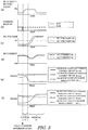
- FIGs. 2A-2F each illustrate respective actions of the converters 5A, 5B, and the control device 8 from the suspension to the activation, and further to the steady state. More specifically, from top to bottom, FIGs. 2A-2F are graphs indicating a change in the DC current setting value Idp ( FIG. 2A ), the current margin ⁇ Id 2 ( FIG. 2B ), the DC voltages Vd 1 , Vd 2 ( FIG. 2C ), the DC currents Id 1 , Id 2 ( FIG. 2D ), the output ⁇ 1ACR of the constant current control circuit 12A in the control circuit 17A, the output ⁇ 1AVR of the constant voltage control circuit 11A and the output ⁇ 1A ⁇ R of the constant margin angle control circuit 10A ( FIG.
- FIGs. 3A-3F illustrate a comparative example.
- both the current setting value Idp and the current margin ⁇ Id 2 are increased, and a control is made so as to satisfy Idp ⁇ ⁇ Id 2 (see FIGS. 2A and 2B ) at the time of activation, but in the comparative example, only the current setting value Idp is increased, and the current margin ⁇ Id 2 remains unchanged from the constant value (see FIGS. 3A and 3B ).
- the actions of the converters 5A, 5B, and the control device 8 are basically the same as those of this embodiment, and only the difference from the example of this embodiment will be explained.
- the DC voltages Vd 1 and Vd 2 are 0 V.
- the respective outputs ⁇ 1AVR , ⁇ 2AVR of the constant current control devices 11A, 11B, and the constant voltage control circuits 12A, 12B of the converters 5A, 5B are suppressed to the initial phase ( ⁇ /2).
- the DC current Id 1 is substantially 0 A, and Id 1 ⁇ Idp is satisfied.
- the output ⁇ 1ACR of the constant current control circuit 12A decreases from the initial phase.
- Input to the constant voltage control circuit 11A is the difference (Vdp-Vd 2 ) between the DC voltage Vd 2 and the DC voltage setting value Vdp.
- Vdp-Vd 2 the difference between the DC voltage Vd 2 and the DC voltage setting value Vdp.
- Vd 2 is extremely small, and Vdp > Vd 2 is satisfied.
- the output ⁇ 1AVR by the constant voltage control circuit 11A increases from the initial phase.
- the constant margin angle control circuit 10A is to suppress a commutation error of the converter 5A, and with no commutation error occurring, this constant margin angle control circuit always has a larger output than the outputs ⁇ 1ACR , ⁇ 1AVR by the constant current control circuit 12A and constant voltage control circuit 11A. Hence, at the time of activation start time point, the output ⁇ 1ACR by the constant current control circuit 12A becomes the smallest value.
- the minimum value selecting circuit 13A has inputs that are the respective output values of the constant current control circuit 12A, the constant voltage control circuit 11A, and the constant margin angle control circuit 10A, but the output ⁇ 1ACR by the constant current control circuit 12A that is the smallest value among those values is output to the converter 5A as a control angle ⁇ 1 .
- the input to the constant current control circuit 12A is (Id 1 -Idp), and in the initial stage of the interval (1) right after the start of activation, as illustrated in FIG. 2D , since the DC current Id 1 is substantially 0 A, a time until the constant current control circuit 12A reaches the steady state depends on the DC current setting value Idp.
- the input to the constant current control circuit 12A is increased in the negative direction.
- the output ⁇ 1ACR by the constant current control circuit 12A is keenly decreased, and the control angle ⁇ 1 to be output to the converter 5A is keenly decreased.
- the control angle ⁇ 1 for the converter 5A and the DC voltage Vd 1 have the following relationship expressed by the formula (1).
- Vac1 is the bus line voltage of the AC system 1A
- X 1 is the reactance of the transformer 4A.
- the decreased control angle ⁇ 1 from the initial phase causes the DC voltage Vd 1 to be increased based on the formula (1), and the difference between Vd 1 and the DC voltage across the DC line 3 increases.
- Input to the constant voltage control circuit 11B is the difference between the DC voltage Vd 2 and the DC voltage setting value Vdp, and at the time point of the start of activation, Vdp > Vd 2 is satisfied.
- the output ⁇ 2AVR by the constant voltage control circuit 11B increases from the initial phase.
- the output ⁇ 2A ⁇ R by the constant margin angle control circuit 10B is larger than the respective outputs ⁇ 2ACR , ⁇ 2AVR by the constant current control circuit 12B and the constant voltage control circuit 11B, like the constant margin angle control circuit 10A.
- the output ⁇ 2ACR by the constant current control circuit 12B is smaller than the output ⁇ 2AVR by the constant voltage control circuit 11B, and the output ⁇ 2ACR by the constant current control circuit 12B is output as a control angle ⁇ 2 to the converter 5B from the minimum value selecting circuit 13B.
- control angle ⁇ 2 for the converter 5B and the DC voltage Vd 2 satisfy the following relationship expressed by the formula (2).
- Vac 2 is the bus line voltage of the AC system 1B
- X 2 is the reactance of the transformer 4B.
- the increased control angle ⁇ 2 from the initial phase also increases the DC voltage Vd 2 based on the formula (2).
- Vd 2 ⁇ 3 2 ⁇ V ac 2 cos ⁇ ⁇ 3 ⁇ X 2 Id 2
- the increased current margin ⁇ Id 2 keenly increases the control angle ⁇ 2 to be output to the converter 5B from the initial phase.
- the increased control angle ⁇ 2 causes the DC voltage Vd 2 to be increased based on the formula (2), and decreases the difference between the DC voltage across the DC line 3 and Vd 2 .
- FIG. 2D an action of decreasing the DC current Id 2 but increasing the DC current Id 1 in the interval (1) is achieved. This increases the charging current through the DC line 3, and thus the DC voltages Vd 1 , Vd 2 become close to the DC voltage setting value Vdp at fast speed.
- the minimum value selecting circuit 13B starts outputting the output ⁇ 2AVR by the constant voltage control circuit 11B that is the control angle ⁇ 2 instead of the output ⁇ 2ACR by the constant current control circuit 12B.
- This enables a constant voltage control of the converter 5B.
- the current margin ⁇ Id 2 is increased, as is clear from FIG. 3F that is the comparative example, a time until ⁇ 2AVR ⁇ ⁇ 2ACR is satisfied is reduced in comparison with a case in which only the DC current setting value Idp is increased.
- the value of the increased DC current setting value Idp is smoothly decreased to the value at the steady state after the completion of the activation so as not to give a disturbance to the power system and the DC power transmission. Hence, the activation action completes.
- FIGs. 4A-4F each illustrate actions of the converters 5A, 5B and the control device 8 before the inversion and to the start of the inversion, and further to the steady state. More specifically, from top to bottom, FIGs. 4A-4F are graphs indicating a change in the DC current setting value Idp ( FIG. 4A ), the current margins ⁇ Id 1 , ⁇ Id 2 ( FIG. 4B ), the DC voltages Vd 1 , Vd 2 ( FIG. 4C ), the DC currents Id 1 , Id 2 ( FIG.
- the comparative example is illustrated in FIGs. 5A-5F .
- a control is given in a way that the current margin is changed from ⁇ Id 1 to ⁇ Id 2 , both the DC current setting value Idp and the current margin ⁇ Id 2 are increased, and Idp ⁇ ⁇ Id 2 is satisfied (see FIGS. 4A and 4B ).
- the current setting value Idp is increased, and as illustrated in FIG. 5B , the current margin is changed from ⁇ Id 1 to ⁇ Id 2 only, and the value remains unchanged from the constant value (see FIGS. 5A and 5B ).
- the actions of the converters 5A, 5B and the control device 8 are basically the same as those of the embodiment. Hence, only the difference from the embodiment will be explained.
- the current margins ⁇ Id 1 , ⁇ Id 2 input to the subtractors 24A, 24B of the setting circuit 21 are changed.
- the current margin ⁇ Id 1 that has been input to the constant current control circuit 12A of the control circuit 17A becomes zero, but the current margin ⁇ Id 2 is now input to the constant current control circuit 12B of the control circuit 17B, and thus the power flow inversion starts.
- the set current margin ⁇ Id 2 is larger than the current margin ⁇ Id 1 , and is larger than the DC current setting value Idp.
- the current margin ⁇ Id 2 is input to the constant current control circuit 12B in the control circuit, and the input of the constant current control circuit 12B becomes (Id 2 + ⁇ Id 2 -Idp). Since Id 2 + ⁇ Id > Idp is satisfied, the output ⁇ 2ACR by the constant current control circuit 12B keeps increasing.
- the minimum value selecting circuit 13B outputs the output ⁇ 2AVR by the constant voltage control circuit 11B that is the control angle ⁇ 2 instead of the output ⁇ 2ACR by the constant current control circuit 12B. This enables the constant voltage control on the converter 5B. Subsequently, as illustrated in FIG. 2A , the value of increased DC current setting value Idp is smoothly decreased to the value in the steady state after the power flow inversion so as not to give a disturbance to the power system and the DC power transmission, and the power flow inversion action completes.
- the increased output ⁇ 2ACR by the constant current control circuit 12B causes the control angle ⁇ 2 to be output to the converter 5B to be keenly increased. Since the control angle is increased, based on the formula (2), the DC voltage Vd 2 becomes close to 0 V, and the difference relative to the DC voltage across the DC line 3 becomes small. Hence, as illustrated in FIG. 4D , an action of further decreasing the DC current Id 2 is achieved.
- the increase of the DC current Id 1 and the decrease of the DC current Id 2 increase the charging-discharging current through the DC line 3, and reduce a time until the polarities of the DC voltages Vd 1 , Vd 2 are inverted and the DC power transmission system reaches the steady state after the power flow inversion. This is apparent when FIG. 4C is compared with the comparative example that is FIG. 5C .
Landscapes
- Engineering & Computer Science (AREA)
- Power Engineering (AREA)
- Inverter Devices (AREA)
- Supply And Distribution Of Alternating Current (AREA)
Abstract
Description
- Embodiments of the present disclosure relate to a control device for power converters which is provided in a DC power transmission system connected to an AC system, and which converts power from AC to DC or from DC to AC.
- DC power transmission systems are applied when, for example, power is utilized between AC systems that have different commercial frequencies. A DC power transmission system includes two power converters which are connected to different AC systems, respectively, and which convert power from AC to DC or from DC to AC, and a DC line that connects the two power converters via a DC reactor.
- Power converters that convert power from AC to DC are called rectifiers, while power converters that convert power from DC to AC are called inverters. When, for example, an AC system A and an AC system B that have different frequencies from each other are connected via a DC power transmission system, and the power is utilized from the AC system A to the AC system B, the power converter at the AC-system-A side serves as the rectifier, while the power converter at the AC-system-B side serves as the inverter. In this case, when the power utilization is switched from the AC system B to the AC system A, the rectifier action and the inverter action are changed over. The change in direction of the power utilization is called a power flowpower flow inversion.
- The power converter is connected to a control device. The control device calculates a control angle for the power converter based on the setting value of a DC current and a DC voltage, the detected voltage and current through the DC line, thereby controlling an activation of the power converter, a power flow inversion, and an inversion prevention action, etc.
- In the cases of, for example, an activation of the DC power transmission system, and a power flow inversion, the control device sets up a current margin for the power converter that will be the inverter, and then outputs the control angle, thereby controlling the power flow direction. In addition, in order to enable a quick transition to the steady state, at the time of activation or the power flow inversion, a DC current setting value is temporarily at a larger value, and the control angle is output.
- Patent Literature 1:
JP H06-276745 A - DC power transmission systems are getting attention not only for the power utilization between AC systems but also for a long-distance and large-capacity power transmission in view of the stability and the economic aspect. This is also because of an increasing attention to renewable energy, such as wind power generation on the ocean, solar power generation at an out-country site, and geothermal power generation, in recent years. When, however, the DC line is extended to a long distance, and a static capacitance thereof increases, a necessary charging current until the DC voltage across the DC line becomes steady increases. Hence, even if the DC current setting value is increased at the time of activation or power flow inversion, a speed-up of the action until becoming the steady state is difficult.
- Embodiments of the present disclosure have been made in view of the foregoing technical problems, and an objective is to provide a power converter control device which is capable of quickly transitioning to a steady state at the time of activation of a DC power transmission system or a power flow inversion.
- In order to achieve the above objective, according to an embodiment, a control device is for a power converter that converts power between two AC systems connected together via a DC line, and includes:
- a constant voltage control circuit outputting a control angle to the power converter based on inputs that are a DC voltage detected value through the DC line and a DC voltage setting value;
- a constant current control circuit outputting a control angle to the power converter based on inputs that are a DC current detected value through the DC line and a DC current setting value;
- a minimum value selecting circuit outputting the control angle for the power converter, the control angle being a minimum value in the control angles output by the constant voltage control circuit and the constant current control circuit;
- a DC current setter setting the DC current setting value; and
- a current margin setter setting a current margin to be input to the power converter when the power converter serves as a inverter,
in which:- the DC current setter increases the DC current setting value when the power converter is activated;
- the current margin setter increases the current margin when the power converter is activated as the inverter; and
- the constant current control circuit outputs the control angle to the power converter serving as the inverter based on a difference between the current margin and the DC current setting value, and the input that is the DC current detected value.
- In addition, according to another embodiment, a control device is for a power converter that converts power between two AC systems connected together via a DC line, and includes:
- a constant voltage control circuit outputting a control angle to the power converter based on inputs that are a DC voltage detected value through the DC line and a DC voltage setting value;
- a constant current control circuit outputting a control angle to the power converter based on an input that is a difference between a DC current detected value through the DC line and a DC current setting value;
- a minimum value selecting circuit outputting the control angle for the power converter, the control angle being a minimum value in the control angles output by the constant voltage control circuit and the constant current control circuit;
- a DC current setter setting the DC current setting value; and
- a current margin setter setting a current margin to be input to the power converter when the power converter serves as a inverter,
in which:- the DC current setter increases the DC current setting value when the power converter is switched from a rectifier to the inverter or from the inverter to the rectifier;
- the current margin setter increases the current margin when the power converter is switched from the rectifier to the inverter; and
- the constant current control circuit outputs the control angle to the power converter serving as the inverter based on a difference between the current margin and the DC current setting value, and the input that is the DC current detected value.
-
-
FIG. 1 is a diagram illustrating a structure of a power converter control device according to an embodiment; -
FIGs. 2A-2F are each a diagram illustrating an exemplary action of when a power converter is activated according to the embodiment; -
FIGs. 3A-3F are each a diagram illustrating an action of when a power converter is activated as a comparative example; -
FIGs. 4A-4F are each a diagram illustrating an exemplary action of the power converter when a power flow inversion is performed according to the embodiment; and -
FIGs. 5A-5F are each a diagram illustrating an action of the power converter when a power flow inversion is performed as a comparative example. - A control device for a power converter according to an embodiment will be explained below with reference to the figures.
- First of all, a structure of a DC power transmission system according to an embodiment, a power converter in the DC power transmission system, and a control device for the power converter will be explained.
FIG. 1 illustrates a main circuit structure of a DCpower transmission system 50, and a structure of a control device 8 forpower converters power transmission system 50 is connected to each of twoAC systems 1A, 1B that have different frequencies, and includes the two power converters (hereinafter, simply referred to as "converter" in some cases) 5A, 5B that convert power from AC to DC or from DC to AC. - In the DC
power transmission system 50, theconverters converter 5A and theconverter 5B are connected to the AC system 1A and theAC system 1B, respectively, viarespective transformers converters DC reactors DC line 3. - In the
converters DC line 3 into AC power. Hence, power is utilized between theAC systems 1A, 1B. - The control device 8 in this embodiment controls the actions of the
converters control circuits converters respective converters DC line 3 are connected toDC voltage detectors current detectors 7A, 7B, respectively. DC voltage detected values (hereinafter, simply referred to as "DC voltage" in some cases) Vd1, Vd2, and DC current detected values (hereinafter, simply referred to as "DC current" in some cases) Id1, Id2 are input to thecontrol circuits converters - The control device 8 further includes a
setting circuit 21 that inputs a current setting value Idp, and current margins ΔId1, ΔId2 to therespective control circuits - The
control circuit 17A includes a constant marginangle control circuit 10A, a constantvoltage control circuit 11A, a constantcurrent control circuit 12A, a minimumvalue selecting circuit 13A, anadder 22A, and asubtractor 23A. Thecontrol circuit 17B also employs the similar structure, and thus the explanation thereof will be omitted. - The setting
circuit 21 includes a DCcurrent setter 16, acurrent margin setter 15A, acurrent margin setter 15B, aswitch 20, andsubtractors - The DC
current setter 16 outputs the DC current setting value Idp to thesubtractors converters - The
current margin setter 15A outputs the current margin ΔId1 of theconverter 5A to thesubtractor 24A. Thecurrent margin setter 15B outputs the current margin ΔId2 of theconverter 5B to the subtractor 24B. The current margins ΔId1, ΔId2 are set to constant values when theconverters converters - The
switch 20 is provided between thecurrent margin setter 15A and thesubtractor 24A, and between thecurrent margin setter 15B and the subtractor 24B, and switches the configuration in a way that the current margin is input to only the converter that will be the inverter. More specifically, when theconverter 5A will be the inverter, the switching is performed in a way that the current margin ΔId1 is input to only thesubtractor 24A, and when theconverter 5B will be the inverter, the switching is performed in such a way that the current margin ΔId2 is input to only the subtractor 24B. - The
subtractor adder control circuit adder control circuit converter 5A will be the inverter, the difference (ΔId1-Idp) between the DC current setting value Idp and the current margin ΔId1 is input to theadder 22A of the control circuit 17. When theconverter 5B will be the inverter, the difference (ΔId2-Idp) between the DC current setting value Idp and the current margin ΔId2 is input to theadder 22B of thecontrol circuit 17B. - Respective detected DC currents Id1, Id2 detected by the DC
current detectors 7A, 7B are also input to theadders respective control circuits adders current control circuits - More specifically, when the
converter 5A will be the rectifier, the difference (Id1-Idp) between the DC current setting value and the DC current is output, and when theconverter 5A will be the inverter, (Id1+ΔId1-Idp) calculated from the DC current setting value, the current margin, and the DC current is output. Likewise, when theconverter 5B will be the rectifier, the difference (Id2-Idp) between the DC current setting value and the DC current is output, and when theconverter 5B will be the inverter, (Id2+ΔId2-Idp) calculated from the DC current setting value, the current margin, and the DC current is output. - A predetermined DC voltage setting value Vdp and respective detected DC voltages Vd1, Vd2 detected by the
DC voltage detectors respective subtractors control circuits subtractors voltage control circuits - The constant
current control circuits adders converters - The constant
voltage control circuits subtractors converters - The constant margin
angle control circuits converters - The minimum
value selecting circuit current control circuit voltage control circuit angle control circuit converter - The action of the DC
power transmission system 50 and the control device 8 for theconverters - At the time of activation of the DC
power transmission system 50, an explanation will be given of an example case in which theconverter 5A is activated as the rectifier, while theconverter 5B is activated as the inverter. That is, theswitch 20 of the settingcircuit 21 switches the configuration in a way that the current margin ΔId2 at the converter-5B side is input to the subtractor 24B. -
FIGs. 2A-2F each illustrate respective actions of theconverters FIGs. 2A-2F are graphs indicating a change in the DC current setting value Idp (FIG. 2A ), the current margin ΔId2 (FIG. 2B ), the DC voltages Vd1, Vd2 (FIG. 2C ), the DC currents Id1, Id2 (FIG. 2D ), the output α1ACR of the constantcurrent control circuit 12A in thecontrol circuit 17A, the output α1AVR of the constantvoltage control circuit 11A and the output α1AγR of the constant marginangle control circuit 10A (FIG. 2E ), and the output α2ACR of the constantcurrent control circuit 12B in thecontrol circuit 17B, the output α2AVR of the constantvoltage control circuit 11B and the output α2AγR of the constant marginangle control circuit 10B (FIG. 2F ). - Note that
FIGs. 3A-3F illustrate a comparative example. According to this embodiment, as explained above, both the current setting value Idp and the current margin ΔId2 are increased, and a control is made so as to satisfy Idp < ΔId2 (seeFIGS. 2A and 2B ) at the time of activation, but in the comparative example, only the current setting value Idp is increased, and the current margin ΔId2 remains unchanged from the constant value (seeFIGS. 3A and 3B ). Also in the comparative example, the actions of theconverters - In the initial stage of suspension, as illustrated in
FIG. 2A , the DC voltages Vd1 and Vd2 are 0 V. As illustrated inFIGS. 2E and 2F , the respective outputs α1AVR, α2AVR of the constantcurrent control devices voltage control circuits converters - At the activation start time point indicated in the lower part of
FIG. 3F , as an action of thecontrol circuit 17A for the rectifier, input to the constantcurrent control circuit 12A is the difference (Id1-Idp) between the DC current Id1 and the DC current setting value Idp. As illustrated inFIG. 2A , in the suspension, although the DC current setting value Idp is set to the constant number like the normal operation, the DC current setting value Idp is increased in an interval (1) after the start of activation. - At the activation start time point, as illustrated in
FIG. 2D , the DC current Id1 is substantially 0 A, and Id1 < Idp is satisfied. Hence, as illustrated inFIG. 2E , the output α1ACR of the constantcurrent control circuit 12A decreases from the initial phase. - Input to the constant
voltage control circuit 11A is the difference (Vdp-Vd2) between the DC voltage Vd2 and the DC voltage setting value Vdp. At the time of activation start time point, as illustrated inFIG. 2C , Vd2 is extremely small, and Vdp > Vd2 is satisfied. Hence, as illustrated inFIG. 2E , the output α1AVR by the constantvoltage control circuit 11A increases from the initial phase. - As explained above, the constant margin
angle control circuit 10A is to suppress a commutation error of theconverter 5A, and with no commutation error occurring, this constant margin angle control circuit always has a larger output than the outputs α1ACR, α1AVR by the constantcurrent control circuit 12A and constantvoltage control circuit 11A. Hence, at the time of activation start time point, the output α1ACR by the constantcurrent control circuit 12A becomes the smallest value. - The minimum
value selecting circuit 13A has inputs that are the respective output values of the constantcurrent control circuit 12A, the constantvoltage control circuit 11A, and the constant marginangle control circuit 10A, but the output α1ACR by the constantcurrent control circuit 12A that is the smallest value among those values is output to theconverter 5A as a control angle α1. - In this case, the input to the constant
current control circuit 12A is (Id1-Idp), and in the initial stage of the interval (1) right after the start of activation, as illustrated inFIG. 2D , since the DC current Id1 is substantially 0 A, a time until the constantcurrent control circuit 12A reaches the steady state depends on the DC current setting value Idp. In this case, in the interval (1) after the start of activation, by increasing the DC current setting value Idp, the input to the constantcurrent control circuit 12A is increased in the negative direction. Hence, as illustrated inFIG. 2E , the output α1ACR by the constantcurrent control circuit 12A is keenly decreased, and the control angle α1 to be output to theconverter 5A is keenly decreased. - In this case, the control angle α1 for the
converter 5A and the DC voltage Vd1 have the following relationship expressed by the formula (1). Note that, in the formula (1), Vac1 is the bus line voltage of the AC system 1A, and X1 is the reactance of thetransformer 4A. The decreased control angle α1 from the initial phase causes the DC voltage Vd1 to be increased based on the formula (1), and the difference between Vd1 and the DC voltage across theDC line 3 increases. Hence, as illustrated inFIG. 2D , the action of further increasing the DC current Id1 is achieved.
[Formula 1]
- On the other hand, as an action of the
control circuit 17B for the inverter, input to the constantcurrent control circuit 12B is (Id2+ΔId2-Idp) calculated based on the difference between the DC current setting value Idp, and, the DC current Id2 and the current margin ΔId2 output by thecurrent margin setter 15B via theswitch 20. Since (Id2+ΔId2 > Idp) is satisfied, the output α2ACR by the constantcurrent control circuit 12B increases from the initial phase in the interval (1). In this case, as explained above, the current margin ΔId2 is changed so as to be larger than the DC current setting value Idp in the interval (1) after the start of activation (seeFIG. 2B ). Hence, the output α2ACR by the constantcurrent control circuit 12B is keenly increased. - Input to the constant
voltage control circuit 11B is the difference between the DC voltage Vd2 and the DC voltage setting value Vdp, and at the time point of the start of activation, Vdp > Vd2 is satisfied. Hence, as illustrated inFIG. 2F , the output α2AVR by the constantvoltage control circuit 11B increases from the initial phase. The output α2AγR by the constant marginangle control circuit 10B is larger than the respective outputs α2ACR, α2AVR by the constantcurrent control circuit 12B and the constantvoltage control circuit 11B, like the constant marginangle control circuit 10A. - In this case, since the input (Id2+ΔId2-Idp) to the constant
current control circuit 12B is small, the output α2ACR by the constantcurrent control circuit 12B is smaller than the output α2AVR by the constantvoltage control circuit 11B, and the output α2ACR by the constantcurrent control circuit 12B is output as a control angle α2 to theconverter 5B from the minimumvalue selecting circuit 13B. - On the other hand, in the
converter 5B, as (Id2+ΔId2-Idp) > 0 is satisfied, as illustrated inFIG. 2F , the output α2ACR by the constantcurrent control circuit 12B keeps increasing. Consequently, the control angle α2 to be output to theconverter 5B also increases. In particular, according to this embodiment, not only the DC current setting value Idp but also the current margin ΔId2 are increased, and Idp < ΔId2 is also satisfied. - If only the DC current setting value Idp is increased, the increase rate of the output α2ACR by the constant
current control circuit 12B becomes gentle, but by increasing the current margin ΔId2 so as to be larger than the DC current setting value Idp, the output α2ACR by the constantcurrent control circuit 12B keenly increases. - In this case, the control angle α2 for the
converter 5B and the DC voltage Vd2 satisfy the following relationship expressed by the formula (2). Note that, in the formula (2), Vac2 is the bus line voltage of theAC system 1B, and X2 is the reactance of thetransformer 4B. The increased control angle α2 from the initial phase also increases the DC voltage Vd2 based on the formula (2).
[Formula 2]
- The increased current margin ΔId2 keenly increases the control angle α2 to be output to the
converter 5B from the initial phase. The increased control angle α2 causes the DC voltage Vd2 to be increased based on the formula (2), and decreases the difference between the DC voltage across theDC line 3 and Vd2. Hence, as illustrated inFIG. 2D , an action of decreasing the DC current Id2 but increasing the DC current Id1 in the interval (1) is achieved. This increases the charging current through theDC line 3, and thus the DC voltages Vd1, Vd2 become close to the DC voltage setting value Vdp at fast speed. - As illustrated in
FIG. 2C , the DC voltages Vd1, Vd2 become close to the DC voltage setting value Vdp in an interval (2). This decreases (Vdp-Vd1) to be input to the constantvoltage control circuit 11B of thecontrol circuit 17B. Consequently, as illustrated inFIG. 2F , the output α2AVR by the constantvoltage control circuit 11B becomes smaller than the output α2ACR by the constantcurrent control circuit 12B. - Since α2AVR < α2ACR is satisfied, the minimum
value selecting circuit 13B starts outputting the output α2AVR by the constantvoltage control circuit 11B that is the control angle α2 instead of the output α2ACR by the constantcurrent control circuit 12B. This enables a constant voltage control of theconverter 5B. In this embodiment, in particular, since the current margin ΔId2 is increased, as is clear fromFIG. 3F that is the comparative example, a time until α2AVR < α2ACR is satisfied is reduced in comparison with a case in which only the DC current setting value Idp is increased. - Subsequently, as illustrated in
FIGS. 2A and 2B , the value of the increased DC current setting value Idp is smoothly decreased to the value at the steady state after the completion of the activation so as not to give a disturbance to the power system and the DC power transmission. Hence, the activation action completes. - At the time of power flow inversion in the DC
power transmission system 50, as an example, an explanation will be given of a case in which, before the power flow inversion, theconverter 5A serves as the inverter, while theconverter 5B serves as the rectifier, and after the power flow inversion, theconverter 5A serves as the rectifier, while theconverter 5B serves as the inverter. -
FIGs. 4A-4F each illustrate actions of theconverters FIGs. 4A-4F are graphs indicating a change in the DC current setting value Idp (FIG. 4A ), the current margins ΔId1, ΔId2 (FIG. 4B ), the DC voltages Vd1, Vd2 (FIG. 4C ), the DC currents Id1, Id2 (FIG. 4D ), and the output α1ACR of the constantcurrent control circuit 12A in thecontrol circuit 17A, the output α1AVR of the constantvoltage control circuit 11A and the output α1AγR of the constant marginangle control circuit 10A (FIG. 4E ), and the output α2ACR of the constantcurrent control circuit 12B in thecontrol circuit 17B, the output α2AVR of the constantvoltage control circuit 11B and the output α2AγR of the constant marginangle control circuit 10B (FIG. 4F ). - As for the power flow inversion, the comparative example is illustrated in
FIGs. 5A-5F . In this embodiment, at the time of power flow inversion, a control is given in a way that the current margin is changed from ΔId1 to ΔId2, both the DC current setting value Idp and the current margin ΔId2 are increased, and Idp < ΔId2 is satisfied (seeFIGS. 4A and 4B ). In contrast, according to the comparative example, only the current setting value Idp is increased, and as illustrated inFIG. 5B , the current margin is changed from ΔId1 to ΔId2 only, and the value remains unchanged from the constant value (seeFIGS. 5A and 5B ). Note that in the comparative example, the actions of theconverters - At the time of the start of power flow inversion indicated by an arrow in the lower part of
FIG. 4F , by switching aswitch 20, the current margins ΔId1, ΔId2 input to thesubtractors circuit 21 are changed. As illustrated inFIG.4B , the current margin ΔId1 that has been input to the constantcurrent control circuit 12A of thecontrol circuit 17A becomes zero, but the current margin ΔId2 is now input to the constantcurrent control circuit 12B of thecontrol circuit 17B, and thus the power flow inversion starts. In this case, the set current margin ΔId2 is larger than the current margin ΔId1, and is larger than the DC current setting value Idp. - In the interval (1) after the start of the power flow inversion, as an action of the
control circuit 17A for the rectifier, ΔId1 is eliminated from the input of the constantcurrent control circuit 12A in the control circuit, and the DC current setting value Idp increases. Hence, the input (Id1-Idp) of the constantcurrent control circuit 12A decreases, and the output α1ACR by the constantcurrent control circuit 12A decreases. The output α1ACR by the constantcurrent control circuit 12A decreases so as to be lower than the output α1AVR by the constantvoltage control circuit 11A, and becomes the minimum value among the inputs to the minimumvalue selecting circuit 13A. Hence, the output α1ACR by the constantcurrent control circuit 12A is output to theconverter 5A as the control angle α1. - On the other hand, as an action of the
control circuit 17B for a inverter, the current margin ΔId2 is input to the constantcurrent control circuit 12B in the control circuit, and the input of the constantcurrent control circuit 12B becomes (Id2+ΔId2-Idp). Since Id2+ΔId > Idp is satisfied, the output α2ACR by the constantcurrent control circuit 12B keeps increasing. - In this case, in the initial stage of the interval (1) after the start of power flow inversion, since the difference between Id1 and Idp is small, a change in output α2ACR by the constant
current control circuit 12A that has an input which is Id1-Idp becomes small. Hence, as illustrated inFIG. 4A , the DC current setting value Idp is increased. Hence, as illustrated inFIG. 4E , the input of the output α1ACR by the constantcurrent control circuit 12A is increased in the negative direction, that is, the output α1ACR by the constantcurrent control circuit 12A is keenly decreased. Consequently, the control angle α1 to be output to theconverter 5A is keenly decreased. Based on the above formula (1), since the control angle α1 becomes small from the value before the start of power flow inversion, the DC voltage Vd1 also keenly decreases, and the voltage difference across theDC line 3 increases. Hence, an action of increasing the DC current Id1 at the time of power flow inversion is achieved. - On the other hand, since (Id2+ΔId2) > Idp is satisfied, (Id2+ΔId2-Idp) to be input to the constant
current control circuit 12B also increases. Consequently, as illustrated inFIG. 4F , the output α2ACR by the constantcurrent control circuit 12B increases. Hence, the control angle α2 to be output to theconverter 5B also increases from the value before the power flow inversion, and based on the above formula (2), the DC voltage Vd2 is coming close to zero. - The decrease of the output α1ACR by the constant
current control circuit 12A and the increase of the output α2ACR by the constantcurrent control circuit 12B continue until the polarities of the DC voltages Vd1 and Vd2 are inverted and the values thereof become the steady value after the power flow inversion. - As illustrated in
FIG. 4C , after the power flow inversion, the DC voltages Vd1, Vd2 become close to the DC voltage setting value Vdp in the interval (2). Accordingly, (Vdp-Vd1) to be input to the constantvoltage control circuit 11B of thecontrol circuit 17B decreases. Consequently, as illustrated inFIG. 4F , the output α2AVR by the constantvoltage control circuit 11B becomes smaller than the output α2ACR by the constantcurrent control circuit 12B. - Since α2AVR < α2ACR is satisfied, the minimum
value selecting circuit 13B outputs the output α2AVR by the constantvoltage control circuit 11B that is the control angle α2 instead of the output α2ACR by the constantcurrent control circuit 12B. This enables the constant voltage control on theconverter 5B. Subsequently, as illustrated inFIG. 2A , the value of increased DC current setting value Idp is smoothly decreased to the value in the steady state after the power flow inversion so as not to give a disturbance to the power system and the DC power transmission, and the power flow inversion action completes. - In this embodiment, as explained above, since the current margin ΔId2 is increased so as to satisfy ΔId2 > Idp, (Id2+ΔId2-Idp) to be input to the constant
current control circuit 12B keenly increases. Consequently, as illustrated inFIG. 4F , the output α2ACR by the constantcurrent control circuit 12B in thecontrol circuit 17B also keenly increases. - The increased output α2ACR by the constant
current control circuit 12B causes the control angle α2 to be output to theconverter 5B to be keenly increased. Since the control angle is increased, based on the formula (2), the DC voltage Vd2 becomes close to 0 V, and the difference relative to the DC voltage across theDC line 3 becomes small. Hence, as illustrated inFIG. 4D , an action of further decreasing the DC current Id2 is achieved. The increase of the DC current Id1 and the decrease of the DC current Id2 increase the charging-discharging current through theDC line 3, and reduce a time until the polarities of the DC voltages Vd1, Vd2 are inverted and the DC power transmission system reaches the steady state after the power flow inversion. This is apparent whenFIG. 4C is compared with the comparative example that isFIG. 5C . -
- (1) As explained above, the control device 8 for the
power converters DC line 3, and includes the constantvoltage control circuits DC line 3, and the DC voltage setting value Vdp, the constantcurrent control circuits DC line 3 , and the DC current setting value Idp, the minimumvalue selecting circuits power converters voltage control circuits current control circuits current setter 16 that sets up the DC current setting value Idp, and thecurrent margin setters power converters power converter 5B is activated as the inverter, the DCcurrent setter 16 increases the DC current setting value Idp, and when thepower converter 5B is activated as the inverter, thecurrent margin setter 15B increases the current margin ΔId2. In addition, the constantcurrent control circuits
By increasing the current margin ΔId2 in addition to the DC current setting value Idp, the output α2ACR by the constantcurrent control circuit 12B at the inverter side is keenly increased, and the DC current Id2 is decreased. On the other hand, the DC current Id1 at the rectifier side is keenly increased in accordance with the increase in DC current setting value Idp. By this, the charging current through theDC line 3 keenly increases, causing the DC voltages Vd1, Vd2 to become close to the DC voltage setting value Vdp at fast speed, resulting in a reduction of a time until the DCpower transmission system 50 reaches the steady state.
Note that when thepower converter 5A is activated as the inverter, by increasing the current margin ΔId1, the same effects can be achieved. - (2) In the control device 8 according to this embodiment, in addition, the DC
current setter 16 increases the DC current set value Idp when thepower converter 5B is switched from the rectifier to the inverter. Still further, thecurrent margin setter 15B increases the current margin ΔId2 when thepower converter 5B is switched from the rectifier to the inverter, and the constantcurrent control circuit 12B outputs the control angle α2ACR based on the inputs that are the difference between the current margin ΔId2 and the DC current set value Idp, and the DC current detected value Id2.
At the time of power flow inversion, by increasing the current margin ΔId2 in addition to the DC current setting value Idp, the output α2ACR by the constantcurrent control circuit 12B at the inverter side is keenly increased, and the DC current Id2 is decreased. On the other hand, the DC current Id1 at the rectifier side is keenly increased by the increased DC current setting value Idp. This increases the charging-discharging current through theDC line 3, and reduces the time until the polarities of the DC voltages Vd1, Vd2 are inverted and reaching the steady state after the power flow inversion.
Note that when thepower converter 5A is switched from the rectifier to the inverter, by increasing the current margin ΔId2, the same effects can be achieved. - (3) Still further, according to this embodiment, at the time of activation and power flow inversion, the
current margin setter 15B sets the current margin to be larger than the increased DC current setting value Idp by the DCcurrent setter 16. This further keenly increases the output α2ACR by the constantcurrent control circuit 12B at the inverter side based on the input that is (Id2+ΔId2-Idp), enabling an achievement of a further quick transition of the DCpower transmission system 50 to the steady state. -
- (1) In the above embodiment, the explanation has been given of the example DC
power transmission system 50 that connects the twodifferent AC systems 1A, 1B, but the present disclosure is also applicable to DC power transmission systems that connect an AC system, and a power generation plant which utilizes renewable energies, such as solar light power generation, wind power generation, geothermal power generation, and water power generation. - (2) The present disclosure is not directly limited to the foregoing embodiment, and can be embodied with a modification to the structural component that does not depart from the scope of the present disclosure when carried out. In addition, appropriate combinations of the multiple structural components disclosed in the foregoing embodiment can form various kinds of invention. For example, some structural components may be omitted from the entire structural components disclosed in the foregoing embodiment. In addition, structural components across different embodiments may be combined as appropriate.
-
- 1A, 1B
- AC system
- 2A, 2B
- DC reactor
- 3
- DC line
- 4A, 4B
- Transformer
- 5A, 5B
- Power converter
- 6A, 6B
- DC voltage detector
- 7A, 7B
- DC current detector
- 8
- Control device
- 10A, 10B
- Constant margin angle control circuit
- 11A, 11B
- Constant voltage control circuit
- 12A, 12B
- Constant current control circuit
- 13A, 13B
- Minimum value selecting circuit
- 15A, 15B
- Current margin setter
- 16
- DC current setter
- 17A, 17B
- Control circuit
- 20
- Switch
- 21
- Setting circuit
- 22A, 22B
- Adder
- 23A, 23B
- Subtractor
- 24A, 24B
- Subtractor
- 50
- DC power transmission system
Claims (4)
- A control device for a power converter that converts power between two AC systems connected together via a DC line, the control device comprising:a constant voltage control circuit outputting a control angle to the power converter based on inputs that are a DC voltage detected value through the DC line and a DC voltage setting value;a constant current control circuit outputting a control angle to the power converter based on inputs that are a DC current detected value through the DC line and a DC current setting value;a minimum value selecting circuit outputting the control angle for the power converter, the control angle being a minimum value in the control angles output by the constant voltage control circuit and the constant current control circuit;a DC current setter setting up the DC current setting value; anda current margin setter setting up a current margin to be input to the power converter when the power converter serves as a inverter,
wherein:the DC current setter increases the DC current setting value when the power converter is activated;the current margin setter increases the current margin when the power converter is activated as the inverter; andthe constant current control circuit outputs the control angle to the power converter serving as the inverter based on a difference between the current margin and the DC current setting value, and the input that is the DC current detected value. - The power converter control device according to claim 1, wherein the current margin setter increases the current margin to be larger than the increased DC current setting value by the DC current setter when the power converter is activated as the inverter.
- A control device for a power converter that converts power between two AC systems connected together via a DC line, the control device comprising:a constant voltage control circuit outputting a control angle to the power converter based on inputs that are a DC voltage detected value through the DC line and a DC voltage setting value;a constant current control circuit outputting a control angle to the power converter based on an input that is a difference between a DC current detected value through the DC line and a DC current setting value;a minimum value selecting circuit outputting the control angle for the power converter, the control angle being a minimum value in the control angles output by the constant voltage control circuit and the constant current control circuit;a DC current setter setting up the DC current setting value; anda current margin setter setting up a current margin to be input to the power converter when the power converter serves as a inverter,
wherein:the DC current setter increases the DC current setting value when the power converter is switched from a rectifier to the inverter or from the inverter to the rectifier;the current margin setter increases the current margin when the power converter is switched from the rectifier to the inverter; andthe constant current control circuit outputs the control angle to the power converter serving as the inverter based on a difference between the current margin and the DC current setting value, and the input that is the DC current detected value. - The power converter control device according to claim 3, wherein the current margin setter increases the current margin to be larger than the increased DC current setting value by the DC current setter when the power converter is switched from the rectifier to the inverter.
Applications Claiming Priority (2)
| Application Number | Priority Date | Filing Date | Title |
|---|---|---|---|
| JP2014124798A JP2016005374A (en) | 2014-06-17 | 2014-06-17 | Control device for power converter |
| PCT/JP2015/064981 WO2015194325A1 (en) | 2014-06-17 | 2015-05-26 | Power converter control device |
Publications (2)
| Publication Number | Publication Date |
|---|---|
| EP3160030A1 true EP3160030A1 (en) | 2017-04-26 |
| EP3160030A4 EP3160030A4 (en) | 2018-03-14 |
Family
ID=54935319
Family Applications (1)
| Application Number | Title | Priority Date | Filing Date |
|---|---|---|---|
| EP15809865.7A Withdrawn EP3160030A4 (en) | 2014-06-17 | 2015-05-26 | Power converter control device |
Country Status (3)
| Country | Link |
|---|---|
| EP (1) | EP3160030A4 (en) |
| JP (1) | JP2016005374A (en) |
| WO (1) | WO2015194325A1 (en) |
Cited By (1)
| Publication number | Priority date | Publication date | Assignee | Title |
|---|---|---|---|---|
| EP3288166A4 (en) * | 2015-04-23 | 2018-09-12 | Kabushiki Kaisha Toshiba | Control device for power converter |
Families Citing this family (1)
| Publication number | Priority date | Publication date | Assignee | Title |
|---|---|---|---|---|
| CN114075677B (en) * | 2021-10-14 | 2023-06-02 | 清华大学 | Parameter control method, device, equipment and storage medium of hydrogen production system |
Family Cites Families (6)
| Publication number | Priority date | Publication date | Assignee | Title |
|---|---|---|---|---|
| JPS5467646A (en) * | 1977-11-09 | 1979-05-31 | Hitachi Ltd | Tidal alteration time current setting control system |
| JPS5594534A (en) * | 1979-01-08 | 1980-07-18 | Hitachi Ltd | Device for removing and detecting fault of dc transmission line |
| JPS60241715A (en) * | 1984-05-11 | 1985-11-30 | 東京電力株式会社 | Operation system of dc transmitter |
| JPH05207650A (en) * | 1992-01-23 | 1993-08-13 | Toshiba Corp | Controller for dc transmission system |
| JPH06276745A (en) * | 1993-03-15 | 1994-09-30 | Toshiba Corp | Controller for ac-dc converter |
| SE9403486L (en) * | 1994-10-13 | 1996-04-14 | Asea Brown Boveri | Method and apparatus for controlling a plant for transmission of high voltage direct current |
-
2014
- 2014-06-17 JP JP2014124798A patent/JP2016005374A/en active Pending
-
2015
- 2015-05-26 WO PCT/JP2015/064981 patent/WO2015194325A1/en not_active Ceased
- 2015-05-26 EP EP15809865.7A patent/EP3160030A4/en not_active Withdrawn
Cited By (1)
| Publication number | Priority date | Publication date | Assignee | Title |
|---|---|---|---|---|
| EP3288166A4 (en) * | 2015-04-23 | 2018-09-12 | Kabushiki Kaisha Toshiba | Control device for power converter |
Also Published As
| Publication number | Publication date |
|---|---|
| EP3160030A4 (en) | 2018-03-14 |
| JP2016005374A (en) | 2016-01-12 |
| WO2015194325A1 (en) | 2015-12-23 |
Similar Documents
| Publication | Publication Date | Title |
|---|---|---|
| US11239664B2 (en) | Power conversion system | |
| US20180166883A1 (en) | Low voltage ride-through control system and method for multi-inverter grid-connected power converter | |
| US9312788B2 (en) | Control device of power conversion unit and method of controlling power conversion unit | |
| US10784683B2 (en) | Method of controlling electrical power system and apparatus using the same | |
| EP3098953A2 (en) | Pre-charge circuit and photovoltaic inverter | |
| EP3176939B1 (en) | Power conversion control device and solar power generation system | |
| CN103597694B (en) | The operating control device of solar power system | |
| CN103986403A (en) | Variable-frequency speed control system and method | |
| EP3261208B1 (en) | Control device of power converter | |
| EP3026775A1 (en) | Control device for solar power generation inverter | |
| EP2731222A1 (en) | Power grid reactive compensation method and apparatus, and grid-tied inverter | |
| CN103311957B (en) | A kind of net side converter control method and system | |
| EP2958223A1 (en) | Power-conversion device and method for controlling same | |
| US20170005590A1 (en) | Power converter | |
| WO2015125377A1 (en) | Power conversion device and power conversion device control method | |
| CN110249497B (en) | Regulating method of bus voltage and relative equipment | |
| EP3836331A1 (en) | Power conversion device | |
| JP6583922B2 (en) | Power converter | |
| US10637249B2 (en) | Inverter anti-islanding control system | |
| JP2008228494A (en) | Inverter for coordinating system | |
| JP6258806B2 (en) | Power converter for grid connection | |
| US11081890B2 (en) | Power generation system of a multi-converter wind turbine and control method thereof | |
| WO2015194325A1 (en) | Power converter control device | |
| CN115833164A (en) | Three-phase energy mutual-aid control method and system in micro-grid | |
| JP2019054641A (en) | Power conversion equipment |
Legal Events
| Date | Code | Title | Description |
|---|---|---|---|
| STAA | Information on the status of an ep patent application or granted ep patent |
Free format text: STATUS: THE INTERNATIONAL PUBLICATION HAS BEEN MADE |
|
| PUAI | Public reference made under article 153(3) epc to a published international application that has entered the european phase |
Free format text: ORIGINAL CODE: 0009012 |
|
| STAA | Information on the status of an ep patent application or granted ep patent |
Free format text: STATUS: REQUEST FOR EXAMINATION WAS MADE |
|
| 17P | Request for examination filed |
Effective date: 20170116 |
|
| AK | Designated contracting states |
Kind code of ref document: A1 Designated state(s): AL AT BE BG CH CY CZ DE DK EE ES FI FR GB GR HR HU IE IS IT LI LT LU LV MC MK MT NL NO PL PT RO RS SE SI SK SM TR |
|
| AX | Request for extension of the european patent |
Extension state: BA ME |
|
| DAV | Request for validation of the european patent (deleted) | ||
| DAX | Request for extension of the european patent (deleted) | ||
| A4 | Supplementary search report drawn up and despatched |
Effective date: 20180209 |
|
| RIC1 | Information provided on ipc code assigned before grant |
Ipc: H02M 7/72 20060101ALI20180205BHEP Ipc: H02M 7/757 20060101ALI20180205BHEP Ipc: H02M 7/48 20070101AFI20180205BHEP Ipc: H02J 3/36 20060101ALI20180205BHEP |
|
| STAA | Information on the status of an ep patent application or granted ep patent |
Free format text: STATUS: EXAMINATION IS IN PROGRESS |
|
| 17Q | First examination report despatched |
Effective date: 20181211 |
|
| STAA | Information on the status of an ep patent application or granted ep patent |
Free format text: STATUS: THE APPLICATION HAS BEEN WITHDRAWN |
|
| 18W | Application withdrawn |
Effective date: 20190418 |