EP3159951A1 - Rechargeable battery module - Google Patents
Rechargeable battery module Download PDFInfo
- Publication number
- EP3159951A1 EP3159951A1 EP16194552.2A EP16194552A EP3159951A1 EP 3159951 A1 EP3159951 A1 EP 3159951A1 EP 16194552 A EP16194552 A EP 16194552A EP 3159951 A1 EP3159951 A1 EP 3159951A1
- Authority
- EP
- European Patent Office
- Prior art keywords
- unit cells
- rechargeable battery
- battery module
- side plate
- stepped portion
- Prior art date
- Legal status (The legal status is an assumption and is not a legal conclusion. Google has not performed a legal analysis and makes no representation as to the accuracy of the status listed.)
- Granted
Links
Images




Classifications
-
- H—ELECTRICITY
- H01—ELECTRIC ELEMENTS
- H01M—PROCESSES OR MEANS, e.g. BATTERIES, FOR THE DIRECT CONVERSION OF CHEMICAL ENERGY INTO ELECTRICAL ENERGY
- H01M50/00—Constructional details or processes of manufacture of the non-active parts of electrochemical cells other than fuel cells, e.g. hybrid cells
- H01M50/20—Mountings; Secondary casings or frames; Racks, modules or packs; Suspension devices; Shock absorbers; Transport or carrying devices; Holders
- H01M50/204—Racks, modules or packs for multiple batteries or multiple cells
- H01M50/207—Racks, modules or packs for multiple batteries or multiple cells characterised by their shape
- H01M50/209—Racks, modules or packs for multiple batteries or multiple cells characterised by their shape adapted for prismatic or rectangular cells
-
- H—ELECTRICITY
- H01—ELECTRIC ELEMENTS
- H01M—PROCESSES OR MEANS, e.g. BATTERIES, FOR THE DIRECT CONVERSION OF CHEMICAL ENERGY INTO ELECTRICAL ENERGY
- H01M50/00—Constructional details or processes of manufacture of the non-active parts of electrochemical cells other than fuel cells, e.g. hybrid cells
- H01M50/50—Current conducting connections for cells or batteries
- H01M50/502—Interconnectors for connecting terminals of adjacent batteries; Interconnectors for connecting cells outside a battery casing
- H01M50/507—Interconnectors for connecting terminals of adjacent batteries; Interconnectors for connecting cells outside a battery casing comprising an arrangement of two or more busbars within a container structure, e.g. busbar modules
-
- H—ELECTRICITY
- H01—ELECTRIC ELEMENTS
- H01M—PROCESSES OR MEANS, e.g. BATTERIES, FOR THE DIRECT CONVERSION OF CHEMICAL ENERGY INTO ELECTRICAL ENERGY
- H01M50/00—Constructional details or processes of manufacture of the non-active parts of electrochemical cells other than fuel cells, e.g. hybrid cells
- H01M50/50—Current conducting connections for cells or batteries
- H01M50/502—Interconnectors for connecting terminals of adjacent batteries; Interconnectors for connecting cells outside a battery casing
- H01M50/509—Interconnectors for connecting terminals of adjacent batteries; Interconnectors for connecting cells outside a battery casing characterised by the type of connection, e.g. mixed connections
-
- H—ELECTRICITY
- H01—ELECTRIC ELEMENTS
- H01M—PROCESSES OR MEANS, e.g. BATTERIES, FOR THE DIRECT CONVERSION OF CHEMICAL ENERGY INTO ELECTRICAL ENERGY
- H01M2220/00—Batteries for particular applications
- H01M2220/20—Batteries in motive systems, e.g. vehicle, ship, plane
-
- Y—GENERAL TAGGING OF NEW TECHNOLOGICAL DEVELOPMENTS; GENERAL TAGGING OF CROSS-SECTIONAL TECHNOLOGIES SPANNING OVER SEVERAL SECTIONS OF THE IPC; TECHNICAL SUBJECTS COVERED BY FORMER USPC CROSS-REFERENCE ART COLLECTIONS [XRACs] AND DIGESTS
- Y02—TECHNOLOGIES OR APPLICATIONS FOR MITIGATION OR ADAPTATION AGAINST CLIMATE CHANGE
- Y02E—REDUCTION OF GREENHOUSE GAS [GHG] EMISSIONS, RELATED TO ENERGY GENERATION, TRANSMISSION OR DISTRIBUTION
- Y02E60/00—Enabling technologies; Technologies with a potential or indirect contribution to GHG emissions mitigation
- Y02E60/10—Energy storage using batteries
-
- Y—GENERAL TAGGING OF NEW TECHNOLOGICAL DEVELOPMENTS; GENERAL TAGGING OF CROSS-SECTIONAL TECHNOLOGIES SPANNING OVER SEVERAL SECTIONS OF THE IPC; TECHNICAL SUBJECTS COVERED BY FORMER USPC CROSS-REFERENCE ART COLLECTIONS [XRACs] AND DIGESTS
- Y02—TECHNOLOGIES OR APPLICATIONS FOR MITIGATION OR ADAPTATION AGAINST CLIMATE CHANGE
- Y02P—CLIMATE CHANGE MITIGATION TECHNOLOGIES IN THE PRODUCTION OR PROCESSING OF GOODS
- Y02P70/00—Climate change mitigation technologies in the production process for final industrial or consumer products
- Y02P70/50—Manufacturing or production processes characterised by the final manufactured product
Definitions
- the present invention relates to a rechargeable battery module which accommodates a plurality of unit cells.
- a rechargeable battery differs from a primary battery in that it can be repeatedly charged and discharged, while the latter is incapable of being recharged.
- Low-capacity rechargeable batteries are used in small portable electronic devices, e.g., mobile phones, notebook computers, and camcorders, while high-capacity rechargeable batteries can be used as a power source for driving motors, e.g., of a hybrid vehicle, an electric vehicle, and the like.
- the rechargeable battery may be used in small electronic devices as a single cell battery or in motor-driving power sources, etc. as a battery module in which a plurality of battery cells are electrically connected or as a battery pack in which a plurality of battery modules are electrically connected.
- a rechargeable battery module may be formed by arranging a plurality of unit cells in one direction, disposing end plates at opposite ends of the arranged direction of the unit cells, disposing side plates at opposite sides of the arranged direction, and welding the side plates to the end plates.
- a rechargeable battery module is required to occupy a minimum space inside a device in which the rechargeable battery module is installed and to deliver a maximum output that maximizes its efficiency.
- a thickness of the side plate thereof and a distance between the side plate and the unit cells are considerably limited.
- the present invention has been made in an effort to provide a rechargeable battery module that provides maximum output in a minimum space despite the structural limitation of a side plate thereof.
- the present invention sets out to provide a rechargeable battery module that maximizes efficiency.
- An embodiment of the present invention provides a rechargeable battery module, including unit cells that are arranged in a first direction, a bus bar that electrically connects the unit cells, a pair of end plates that are spaced apart from each other along the first direction at opposite ends of the unit cells to support the unit cells, and at least one side plate between the pair of end plates and connected to the pair of end plates, the at least one side plate extending along the unit cells and spaced apart from the unit cells a predetermined distance, wherein the side plate includes a stepped portion that is formed within the predetermined distance.
- a plurality of stepped portions may be formed in the second direction.
- the stepped portion may include a base that is flatly formed at the outermost side of the second direction, and at least one protruding portion that protrude toward the unit cells from the base.
- the base and the protruding portion may be connected at a right angle.
- the side plate may be provided with a through-hole adjacent to the unit cell.
- a plurality of through holes may be formed along a third direction crossing the first and the second directions.
- the stepped portion may be at each of the plurality of through holes.
- the rechargeable battery module may further include an insulating sheet that is adhered to the protruding portion adjacent to the unit cell.
- a height of the protrude portion may be about 30 % to 40 % of the thickness of the side plate.
- the protruding portion may gradually decrease and protrude from the base to the unit cells.
- the protruding portion may repeatedly be directed from the base to the unit cells and directed from the unit cells to an opposite side thereof.
- the side plate may be formed of a metal sheet with a predetermined thickness, and the stepped portion may extend an entire thickness of the side plate in the second direction.
- the side plate may include a flange that is bent at a lower end portion of a third direction crossing the first and the second direction to support the unit cells.
- the flange may include a rib that protrudes in the third direction and extends in the first direction.
- the rechargeable battery module may further include an end support that is provided between the end plate and an outermost unit cell and is formed of an insulator.
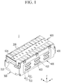
- FIG. 1 illustrates a perspective view of a rechargeable battery module according to a first embodiment of the present invention
- FIG. 2 illustrates an exploded perspective view of the rechargeable battery module in FIG.1
- a rechargeable battery module 1 of the first embodiment of the present invention may include unit cells 100 with corresponding rechargeable batteries, a bus bar 200 that electrically connects the unit cells 100, and end plates 300 and side plates 400 that support and accommodate the unit cells 100.
- the unit cells 100 are disposed to be adjacent in a first direction (x-axis direction), and are electrically and structurally connected to each other to form the rechargeable battery module 1.
- the bus bar 200 electrically connects the unit cells 100, and is disposed on an upper portion of the rechargeable battery module 1.
- the bus bar 200 may connect four neighboring unit cells 100 in parallel in the rechargeable battery 1, and may connect the four parallel-connected unit cells 100 with another four (or more) neighboring parallel-connected unit cells 100 in series.
- a pair of end plates 300 are provided, and the end plates 300 are disposed at opposite ends of the x-axis direction to respectively support outermost unit cells 100.
- the end plates 300 support the unit cells 100 by interposing an end support 310 between opposite inner sides of a length direction (x-axis direction) of the rechargeable battery module 1.
- the end plate 300 is formed of metal, e.g., stainless still, and provides rigidity to the rechargeable battery module 1 at the outermost of the x-axis direction.
- the end support 310 supports the unit cells 100, and is formed of an electrical insulator to electrically insulate the end plate 300 from the unit cells 100.
- a pair of side plates 400 are connected to the end plates 300 and are disposed at opposite sides of a second direction (y-axis direction) crossing the x-axis direction, i.e., the side plates 400 are spaced apart from each other in the second direction.
- the side plates 400 each include a base 411 that is separated from the unit cells 100 by a gap G (refer to FIG. 5 ).
- the side plates 400 therefore support and accommodate the unit cells 100 at opposite sides of a width direction of the rechargeable battery module 1.
- Each side plate 400 may include stepped portions 410 that are formed within the gap G.
- the unit cells 100 accommodated in a space set by the interconnected end plate 300 and the side plate 400 may be covered by a bus bar holder 600.
- the bus bar holder 600 may be provided with bus bar holes 610, and the bus bar 200 may be electrically connected to the unit cells 100 through the bus bar holes 610.
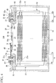
- FIG. 3 illustrates a perspective view of a rechargeable battery in one unit cell 100
- FIG. 4 illustrates a cross-sectional view of FIG. 3 taken along line IV-IV.
- the unit cell 100 includes a rechargeable battery through which a current is charged or discharged.
- each unit cell 100 may include an electrode assembly 10, a case 15 which accommodates the electrode assembly 10, a cap plate 20 that is coupled to an opening of the case 15, a first electrode terminal 21 (hereinafter referred to as “negative terminal”) and a second electrode terminal 22 (hereinafter referred to as “positive terminal”) installed on the cap plate 20, and an external short-circuit part 40 provided at the negative terminal 21.
- a first electrode 11 (hereinafter referred to as "negative electrode") and a second electrode 12 (hereinafter referred to as “positive electrode”) are disposed at opposite sides of a separator 13 which is an insulator, and the negative electrode 11, the separator 13, and the positive electrode 12 are spirally wound in a jelly-roll state.
- the negative electrode 11 and the positive electrode 12 respectively include coated regions 11a and 12a, where an active material is coated on a current collector of a metal plate, and uncoated regions 11b and 12b, where the active material is not coated thereon to expose the current collector.
- the uncoated region 11b of the negative electrode 11 is formed at one end portion of the negative electrode 11 along the spirally wound negative electrode 11.
- the uncoated region 12b of the positive electrode 12 is formed at one end portion of the positive electrode 12 along the spirally wound positive electrode 12.
- the uncoated regions 11b and 12b are disposed at opposite sides of the electrode assembly 10.
- the case 15 may be roughly formed in a cuboid shape to accommodate the electrode assembly 10 and an electrolyte solution, and an opening is formed at one side of the cuboid to connect inner and outer spaces thereof. The opening is formed to allow the electrode assembly 10 to be inserted into the case 15.
- the cap plate 20 is installed in the opening of the case 15 to seal the opening of the case 15.
- the case 15 and the cap plate 20 may be formed of aluminum such that they are welded to each other.
- an electrolyte injection opening 29, a vent hole 24, and terminal holes H1 and H2 are provided in the cap plate 20.
- the electrolyte injection opening 29 allows the electrolyte solutions to be injected into the case 15 after combining the case 15 with the cap plate 20. After injecting the electrolyte solution, the electrolyte injection opening 29 is sealed by a sealing cap 27.
- the vent hole 24 is sealed by a vent plate 25 such that it discharges internal pressure of the unit cell 100.
- the vent plate 25 is ruptured to open the vent hole 24.
- the vent plate 25 has a notch 25a that induces the rupture.
- the bus bar holder 600 further includes a holder vent hole 624 corresponding to the vent hole 24. Accordingly, the internal pressure discharged through the vent hole 24 can be discharged to the outside of the rechargeable battery module 1 through the holder vent hole 624. For example, the internal pressure discharged to the vent hole 24 is not hindered by the bus bar holder 600.
- the negative terminal 21 and the positive terminal 22 are installed in the terminal holes H1 and H2 of the cap plate 20, and are electrically connected to the electrode assembly 10. That is, the negative terminal 21 is electrically connected to the negative electrode 11 of the electrode assembly 10, and the positive terminal 22 is electrically connected to the positive electrode 12 of the electrode assembly 10. Accordingly, the electrode assembly 10 is drawn out of the case 15 through the negative terminal 21 and the positive terminal 22.
- the negative terminal 21 and the positive terminal 22 have the same structure at an inner side of the cap plate 20, the same structures will be described together, and since they have different structures at an outer side of the cap plate 20, the different structures will be separately described.
- the negative and positive terminals 21 and 22 may include rivet terminals 21a and 22a that are respectively installed in the terminal holes H1 and H2 of the cap plate 20, flanges 21b and 22b that are widely formed at the inner side of the cap plate 20 while being integrally formed with the respective rivet terminals 21 a and 22b, and plate terminals 21c and 22c that are disposed outside of the cap plate 20 while being connected to the respective rivet terminals 21 a and 22a by riveting or welding.
- Negative and positive gaskets 36 and 37 are respectively installed between the rivet terminals 21a and 22a of the negative and positive terminals 21 and 22 and the inner sides of the terminal holes H1 and H2 to seal and electrically insulate between the rivet terminals 21a and 22a of the negative and positive terminals 21 and 22 and the cap palate 20.
- the negative and positive gaskets 36 and 37 are installed such that they are further extended between the flanges 21b and 22b and the inner side of the cap plate 20, and further seal and electrically insulate between the flanges 21b and 22b and the cap plate 20.
- the negative and positive gaskets 36 and 37 prevent the electrolyte solution from leaking through the terminal holes H1 and H2.
- Negative and positive electrode lead tabs 51 and 52 electrically connect the negative and positive terminals 21 and 22 to the negative and positive electrodes 11 and 12 of the electrode assembly 10, respectively.
- the negative and positive electrode lead tabs 51 and 52 are connected to the lower end portions of the rivet terminals 21a and 22a while being supported by the flanges 21b and 22b.
- Negative and positive insulating members 61 and 62 are respectively installed between the negative and positive electrode lead tabs 51 and 52 and the cap plate 20 to electrically insulates the negative and positive lead tabs 51 and 52 and the cap plate 20. Further, the negative and positive insulating members 61 and 62 are combined to the cap plate 20 at one side thereof, and enclose the negative and positive lead tabs 51 and 52, the rivet terminals 21a and 22a, and flanges 21b and 22b, thereby stabilizing their connection structure.
- the external short-circuit part 40 will be described in connection with the plate terminal 21c of the negative terminal 21, and a top plate 46 will be described in connection with the plate terminal 22c of the positive terminal 22.
- the external short-circuit part 40 adjacent to the negative terminal 21 may include a short-circuited tab 41 and a short-circuited member 43 that are separated or short-circuited depending on the internal pressure of the unit cell.
- the short-circuit tab 41 is disposed outside of the cap plate 20 with an insulating member 31 therebetween while being electrically connected to the rivet terminal 21a of the negative terminal 21.
- the insulating member 31 is disposed between the short-circuit tab 41 and the cap plate 20 to electrically insulate the short-circuit tab 41 from the cap plate 20.
- the cap plate 20 maintains an electrically insulated state with the negative terminal 21.
- the short-circuit tab 41 and the plate terminal 21c are fastened to the upper end portion of the rivet terminal 21 a.
- the short-circuit tab 41 and the plate terminal 21c are fastened to the cap plate 20 while interposing the insulating member 31 therebetween.
- the short-circuit member 43 is installed in a short-circuit hole 42 which is formed in the cap plate 20. While being connected to the negative terminal 21, the short-circuit tab 41 is disposed to be extended along the outside of the short-circuit member 43. Thus, the short-circuit tab 41 and the short-circuit member 43 correspond to the shot-circuit hole 42, face each other to maintain a separated state therebetween (solid line state), and may form a short-circuit state (imaginary line state) in which the short-circuit member 43 is inversely deformed when the internal pressure of the unit cell 100 increases.
- the top plate 46 adjacent to the positive terminal 22 electrically connects the plate terminal 22c of the positive terminal 22 and the cap plate 20.
- the top plate 46 is interposed between the plate terminal 2c and the cap plate 20, and is penetrated by the rivet terminal 22a.
- the top plate 46 and the plate terminal 22c are fastened to the upper end portion of the rivet terminal 22a.
- the plate terminal 22c is disposed at the outside of the cap plate 20 while interposing the top plate 46 therebetween.
- the positive electrode gasket 37 is installed such that it is further extended between the rivet terminal 22a and the top plate 46.
- the positive electrode gasket 37 prevents the rivet terminal 22a and the top plate 46 from being directly electrically connected each other.
- the rivet terminal 22a is electrically connected to the top plate 46 through the plate terminal 22c.
- FIG. 5 illustrates a cross-sectional view of FIG. 2 taken along line V-V.
- the plurality of stepped portions 410 may be formed in the side plate 400 in the second direction (y-axis direction). As illustrated in FIG.5 , a first end of the stepped portion 410 is connected to the base 411, while a second end of the stepped portion 410 contacts an insulating sheet 500 on the unit cell 100.
- Each stepped portion 410 may define a through-hole 413 through the side plate 400 to have a depth in the second direction.
- the base 411 is flatly formed at the outermost side of the second direction (y-axis direction) and steps 412 progressively protrude toward the unit cell 100 from the base 411 within each stepped portion 410.
- the steps 412 successively decrease in width from the base 411 toward the unit cells 100.
- the steps 412 together define a series of steps extending from the base 411 toward the unit cell 100.
- the steps 412 may include two steps that are gradually recessed in the y-axis direction.
- Each step 412 comprises a step plate that is aligned parallel to the plate 11 and a riser that extends towards the unit cell (i.e. in the y direction).
- the base 411 and the riser of the outermost step 412 are connected at a right angle, furthermore the base of the outermost step and the riser of the next step in are connected at a right angle. Successive steps may be similarly connected.
- each step 412 may have a closed shape, e.g., an oval or circular shape.
- a first diameter D1 defined by the outermost part of the stepped portion 410 in a third direction (z-axis) may be greater than a second diameter D2 defined by the innermost part of the stepped portion 410 in the third direction.
- the side plate 400 is provided with the through-hole 413 in the step 412 that is innermost and adjacent to the unit cell 100.
- the second diameter D2 defines the through-hole 413 of the side plate 400.
- the through-hole 413 is formed to reduce the weight of the side plate 400.
- a plurality of through-holes 413 may be provided along the x-axis direction and the z-axis direction. The plurality of the through holes 413 may further reduce the weight of the side plate 400 while maintaining the rigidity of the side plate 400.
- the stepped portion 410 is provided to correspond to each of the plurality of the through-holes 413, and is connected to the base 411 at the right angle, thereby preventing a spring back of the side plate 400 which is formed of a thin sheet of material.
- the stepped portion 410 may further strengthen the rigidity of the side plate which can be weakened due to the through-hole 413.
- a protrusion height H that the stepped portion 410 projects toward the unit cell 100 may be about 30% to about 40% of the thickness T of the side plate 400.
- the protrusion height H along the y-axis may be about 0.24 mm to about 0.32 mm, e.g., about 0.30 mm.
- the protrusion height H of the stepped portion 410 is greater than about 40% of the thickness T of the side plate 400, a crack may occur around the stepped portion 410. If the protrusion height H of the stepped portion 410 is less than about 30% of the thickness T of the side plate, it may be difficult to substantially strengthen the rigidity at the stepped portion 410.
- the side plate 400 is formed of a thin plate of a metal sheet with a predetermined thickness T, e.g., about 0.8 mm.
- the side plate 400 may be formed of a thin plate of stainless steel.
- the stepped portion 410 is formed on a predetermined portion of the side plate 400 and increases an entire thickness T' of the y-axis direction within the distance G, it may maintain a shape of the thin plate metal sheet.
- the side plate 400 may be formed of a thin plate, and may accommodate and support the unit cells 100 while maintaining the rigidity within the narrow distance G between the unit cells 100, thereby maximizing optimization of the rechargeable battery module 1.
- the insulating sheet 500 may be further provided between the side plate 400 and the unit cells 100.
- the insulating sheet 500 electrically insulates the side plate 400 and the unit cells 100. In this case, a fine gap may be formed between the insulating sheet 500 and the unit cells 100.
- the insulating sheet 500 may be adhered to the step 412 that is closest to the unit cell 100 in the side plate 400, i.e., to the innermost part of the stepped portion 410.
- the insulating sheet 500 may be adhered to the protruding portion 412 of the side plate 400 by a double-sided adhesive tape.
- the side plate 400 may further include a flange 420 that supports the, e.g., bottom of the, unit cells 100.
- the flange 420 is bent in the y-axis direction from a lower end portion of the side plate 400.
- the flange 420 may further include a rib 421 which protrudes in the z-axis direction and extends in the x-axis direction.
- the rib 421 is formed to have a semi-circular shape with two lines on the flange 420, and stably supports the lower end portion of the unit cells 100.
- the flange 420 allows a lower plate supporting the lower end portion of the unit cells 100 to be removed in the rechargeable battery module 1, thereby reducing the weight of the rechargeable battery module 1. Further, when the rechargeable battery module 1 is installed in a system (e.g., electric vehicle), the flange 420 allows the unit cells 100 to be directly adhered to a cooling device, thereby realizing effective cooling.
- a system e.g., electric vehicle
- the side plate 400 is provided with a connecting portion 430 incised on an upper end of an opposite side of the flange 420.
- the connecting part 430 is formed to be bent toward the bus bar holder 600 from the base 411 of the side plate 400 to be elastically supported to the bus bar holder 600.
- the connecting portion 430 may be welded and connected to a bracket 620 that is provided at a position corresponding to the bus bar holder 600.
- the bracket 620 is provided in the bus bar holder 600 by insert molding.
- the rechargeable battery module 1 is completed by covering the unit cells 100 with the bus bar holder 600, connecting the unit cells 100 to the bus bar 200 through the bus bar hole 610, and welding the connecting portion 430 of the side plate 400 to the bracket 620 of the bus bar holder 600 after connecting the end plate 300 and the side plate 400 and then accommodating and supporting the unit cells 100.
- the unit cells 100 are supported and accommodated by the end plate 300 and the side plate 400 at the side thereof, by the bus bar holder 600 at the upper portion thereof, and by the flange 420 of the side plate 400 at the lower portion thereof.
- FIG. 6 illustrates a partial cross-sectional view of a rechargeable battery module according to a second embodiment of the present invention.
- a step 712 of a stepped portion 710 is directed to the unit cells 100 from a base 711, and repeatedly protrudes toward the opposite side of the unit cells 100.
- the second embodiment may strengthen the rigidity of the side plate 700 by effectively forming step 712 within a narrow distance G2, even when the distance G2 between the unit cells 100 and the side plate 700 is narrow.
- a stepped portion is formed in the side plate that maintains an interval from the unit cells, thereby maintaining rigidity and flatness of the side plate. Accordingly, the rechargeable battery module according to the embodiment of the present disclosure may provide the maximum output in the minimum space despite structural limitations of the side plate. That is, according to the embodiment of the present disclosure, efficiency of the rechargeable battery module may be maximized.
Landscapes
- Chemical & Material Sciences (AREA)
- Chemical Kinetics & Catalysis (AREA)
- Electrochemistry (AREA)
- General Chemical & Material Sciences (AREA)
- Battery Mounting, Suspending (AREA)
- Connection Of Batteries Or Terminals (AREA)
- Engineering & Computer Science (AREA)
- Manufacturing & Machinery (AREA)
Abstract
Description
- The present invention relates to a rechargeable battery module which accommodates a plurality of unit cells.
- A rechargeable battery differs from a primary battery in that it can be repeatedly charged and discharged, while the latter is incapable of being recharged. Low-capacity rechargeable batteries are used in small portable electronic devices, e.g., mobile phones, notebook computers, and camcorders, while high-capacity rechargeable batteries can be used as a power source for driving motors, e.g., of a hybrid vehicle, an electric vehicle, and the like.
- The rechargeable battery may be used in small electronic devices as a single cell battery or in motor-driving power sources, etc. as a battery module in which a plurality of battery cells are electrically connected or as a battery pack in which a plurality of battery modules are electrically connected. For example, a rechargeable battery module may be formed by arranging a plurality of unit cells in one direction, disposing end plates at opposite ends of the arranged direction of the unit cells, disposing side plates at opposite sides of the arranged direction, and welding the side plates to the end plates.
- A rechargeable battery module is required to occupy a minimum space inside a device in which the rechargeable battery module is installed and to deliver a maximum output that maximizes its efficiency. However, in the rechargeable battery module, a thickness of the side plate thereof and a distance between the side plate and the unit cells are considerably limited.
- The present invention has been made in an effort to provide a rechargeable battery module that provides maximum output in a minimum space despite the structural limitation of a side plate thereof. In other words, the present invention sets out to provide a rechargeable battery module that maximizes efficiency.
- An embodiment of the present invention provides a rechargeable battery module, including unit cells that are arranged in a first direction, a bus bar that electrically connects the unit cells, a pair of end plates that are spaced apart from each other along the first direction at opposite ends of the unit cells to support the unit cells, and at least one side plate between the pair of end plates and connected to the pair of end plates, the at least one side plate extending along the unit cells and spaced apart from the unit cells a predetermined distance, wherein the side plate includes a stepped portion that is formed within the predetermined distance.
- A plurality of stepped portions may be formed in the second direction.
- The stepped portion may include a base that is flatly formed at the outermost side of the second direction, and at least one protruding portion that protrude toward the unit cells from the base.
- The base and the protruding portion may be connected at a right angle.
- The side plate may be provided with a through-hole adjacent to the unit cell.
- A plurality of through holes may be formed along a third direction crossing the first and the second directions.
- The stepped portion may be at each of the plurality of through holes.
- The rechargeable battery module may further include an insulating sheet that is adhered to the protruding portion adjacent to the unit cell.
- A height of the protrude portion may be about 30 % to 40 % of the thickness of the side plate.
- The protruding portion may gradually decrease and protrude from the base to the unit cells.
- The protruding portion may repeatedly be directed from the base to the unit cells and directed from the unit cells to an opposite side thereof.
- The side plate may be formed of a metal sheet with a predetermined thickness, and the stepped portion may extend an entire thickness of the side plate in the second direction.
- The side plate may include a flange that is bent at a lower end portion of a third direction crossing the first and the second direction to support the unit cells.
- The flange may include a rib that protrudes in the third direction and extends in the first direction.
- The rechargeable battery module may further include an end support that is provided between the end plate and an outermost unit cell and is formed of an insulator.
- At least some of the above and other features of the invention are set out in the claims.
- Features of the invention will be made more apparent to those of ordinary skill in the art by describing in detail embodiments thereof with reference to the attached drawings, in which:
-
FIG. 1 illustrates a perspective view of a rechargeable battery module according to a first embodiment of the present invention. -
FIG. 2 illustrates an exploded perspective view of the rechargeable battery module inFIG.1 -
FIG. 3 illustrates an enlarged perspective view of a rechargeable battery inFIG. 2 . -
FIG. 4 illustrates a cross-sectional view ofFIG. 3 taken along line IV-IV. -
FIG. 5 illustrates a cross-sectional view ofFIG.2 taken along line V-V. -
FIG. 6 illustrates a partial cross-sectional view of a rechargeable battery module according to a second embodiment of the present invention. - Example embodiments of the invention will now be described more fully hereinafter with reference to the accompanying drawings; however, the invention may be embodied in different forms and should not be construed as limited to the embodiments set forth herein. Rather, these embodiments are provided so that this disclosure will be thorough and will convey implementations to those skilled in the art.
- In the drawing figures, the dimensions of layers and regions may be exaggerated for clarity of illustration. It will also be understood that when a layer or element is referred to as being "on" another layer or substrate, it can be directly on the other layer or substrate, or intervening layers may also be present. In addition, it will also be understood that when a layer is referred to as being "between" two layers, it can be the only layer between the two layers, or one or more intervening layers may also be present. Like reference numerals refer to like elements throughout.
-
FIG. 1 illustrates a perspective view of a rechargeable battery module according to a first embodiment of the present invention, andFIG. 2 illustrates an exploded perspective view of the rechargeable battery module inFIG.1 - Referring to
FIGS. 1 and2 , arechargeable battery module 1 of the first embodiment of the present invention may includeunit cells 100 with corresponding rechargeable batteries, abus bar 200 that electrically connects theunit cells 100, andend plates 300 andside plates 400 that support and accommodate theunit cells 100. - The
unit cells 100 are disposed to be adjacent in a first direction (x-axis direction), and are electrically and structurally connected to each other to form therechargeable battery module 1. Thebus bar 200 electrically connects theunit cells 100, and is disposed on an upper portion of therechargeable battery module 1. For example, thebus bar 200 may connect four neighboringunit cells 100 in parallel in therechargeable battery 1, and may connect the four parallel-connectedunit cells 100 with another four (or more) neighboring parallel-connectedunit cells 100 in series. - A pair of
end plates 300 are provided, and theend plates 300 are disposed at opposite ends of the x-axis direction to respectively supportoutermost unit cells 100. For example, theend plates 300 support theunit cells 100 by interposing anend support 310 between opposite inner sides of a length direction (x-axis direction) of therechargeable battery module 1. Theend plate 300 is formed of metal, e.g., stainless still, and provides rigidity to therechargeable battery module 1 at the outermost of the x-axis direction. Theend support 310 supports theunit cells 100, and is formed of an electrical insulator to electrically insulate theend plate 300 from theunit cells 100. - A pair of
side plates 400 are connected to theend plates 300 and are disposed at opposite sides of a second direction (y-axis direction) crossing the x-axis direction, i.e., theside plates 400 are spaced apart from each other in the second direction. Theside plates 400 each include abase 411 that is separated from theunit cells 100 by a gap G (refer toFIG. 5 ). Theside plates 400 therefore support and accommodate theunit cells 100 at opposite sides of a width direction of therechargeable battery module 1. Eachside plate 400 may includestepped portions 410 that are formed within the gap G. - The
unit cells 100 accommodated in a space set by the interconnectedend plate 300 and theside plate 400 may be covered by abus bar holder 600. Thebus bar holder 600 may be provided withbus bar holes 610, and thebus bar 200 may be electrically connected to theunit cells 100 through thebus bar holes 610. -
FIG. 3 illustrates a perspective view of a rechargeable battery in oneunit cell 100, andFIG. 4 illustrates a cross-sectional view ofFIG. 3 taken along line IV-IV. Referring toFIGS 3 and4 , theunit cell 100 includes a rechargeable battery through which a current is charged or discharged. - As illustrated in
FIGS. 3-4 , eachunit cell 100 may include anelectrode assembly 10, acase 15 which accommodates theelectrode assembly 10, acap plate 20 that is coupled to an opening of thecase 15, a first electrode terminal 21 (hereinafter referred to as "negative terminal") and a second electrode terminal 22 (hereinafter referred to as "positive terminal") installed on thecap plate 20, and an external short-circuit part 40 provided at thenegative terminal 21. - For example, in the
electrode assembly 10, a first electrode 11 (hereinafter referred to as "negative electrode") and a second electrode 12 (hereinafter referred to as "positive electrode") are disposed at opposite sides of aseparator 13 which is an insulator, and thenegative electrode 11, theseparator 13, and thepositive electrode 12 are spirally wound in a jelly-roll state. Thenegative electrode 11 and thepositive electrode 12 respectively include coatedregions uncoated regions uncoated region 11b of thenegative electrode 11 is formed at one end portion of thenegative electrode 11 along the spirally woundnegative electrode 11. Theuncoated region 12b of thepositive electrode 12 is formed at one end portion of thepositive electrode 12 along the spirally woundpositive electrode 12. Theuncoated regions electrode assembly 10. - As an example, the
case 15 may be roughly formed in a cuboid shape to accommodate theelectrode assembly 10 and an electrolyte solution, and an opening is formed at one side of the cuboid to connect inner and outer spaces thereof. The opening is formed to allow theelectrode assembly 10 to be inserted into thecase 15. - The
cap plate 20 is installed in the opening of thecase 15 to seal the opening of thecase 15. For example, thecase 15 and thecap plate 20 may be formed of aluminum such that they are welded to each other. - In addition, an electrolyte injection opening 29, a
vent hole 24, and terminal holes H1 and H2 are provided in thecap plate 20. The electrolyte injection opening 29 allows the electrolyte solutions to be injected into thecase 15 after combining thecase 15 with thecap plate 20. After injecting the electrolyte solution, the electrolyte injection opening 29 is sealed by a sealingcap 27. - The
vent hole 24 is sealed by avent plate 25 such that it discharges internal pressure of theunit cell 100. When the internal pressure of theunit cell 100 reaches a predetermined pressure, thevent plate 25 is ruptured to open thevent hole 24. Thevent plate 25 has anotch 25a that induces the rupture. - Meanwhile, the
bus bar holder 600 further includes aholder vent hole 624 corresponding to thevent hole 24. Accordingly, the internal pressure discharged through thevent hole 24 can be discharged to the outside of therechargeable battery module 1 through theholder vent hole 624. For example, the internal pressure discharged to thevent hole 24 is not hindered by thebus bar holder 600. - The
negative terminal 21 and thepositive terminal 22 are installed in the terminal holes H1 and H2 of thecap plate 20, and are electrically connected to theelectrode assembly 10. That is, thenegative terminal 21 is electrically connected to thenegative electrode 11 of theelectrode assembly 10, and thepositive terminal 22 is electrically connected to thepositive electrode 12 of theelectrode assembly 10. Accordingly, theelectrode assembly 10 is drawn out of thecase 15 through thenegative terminal 21 and thepositive terminal 22. - Since the
negative terminal 21 and thepositive terminal 22 have the same structure at an inner side of thecap plate 20, the same structures will be described together, and since they have different structures at an outer side of thecap plate 20, the different structures will be separately described. - The negative and
positive terminals rivet terminals cap plate 20,flanges cap plate 20 while being integrally formed with therespective rivet terminals plate terminals cap plate 20 while being connected to therespective rivet terminals - Negative and
positive gaskets rivet terminals positive terminals rivet terminals positive terminals cap palate 20. The negative andpositive gaskets flanges cap plate 20, and further seal and electrically insulate between theflanges cap plate 20. For example, as the negative andpositive terminals cap plate 20, the negative andpositive gaskets - Negative and positive
electrode lead tabs positive terminals positive electrodes electrode assembly 10, respectively. For example, by combining the negative and positiveelectrode lead tabs rivet terminals electrode lead tabs rivet terminals flanges - Negative and positive insulating
members electrode lead tabs cap plate 20 to electrically insulates the negative and positivelead tabs cap plate 20. Further, the negative and positive insulatingmembers cap plate 20 at one side thereof, and enclose the negative and positivelead tabs rivet terminals flanges - The external short-
circuit part 40 will be described in connection with theplate terminal 21c of thenegative terminal 21, and atop plate 46 will be described in connection with theplate terminal 22c of thepositive terminal 22. - The external short-
circuit part 40 adjacent to thenegative terminal 21 may include a short-circuitedtab 41 and a short-circuitedmember 43 that are separated or short-circuited depending on the internal pressure of the unit cell. The short-circuit tab 41 is disposed outside of thecap plate 20 with an insulatingmember 31 therebetween while being electrically connected to therivet terminal 21a of thenegative terminal 21. - The insulating
member 31 is disposed between the short-circuit tab 41 and thecap plate 20 to electrically insulate the short-circuit tab 41 from thecap plate 20. For example, thecap plate 20 maintains an electrically insulated state with thenegative terminal 21. - By combining the short-
circuit tab 41 and theplate terminal 21c with an upper end portion of therivet terminal 21 a and then caulking the upper end portion, the short-circuit tab 41 and theplate terminal 21c are fastened to the upper end portion of therivet terminal 21 a. Thus, the short-circuit tab 41 and theplate terminal 21c are fastened to thecap plate 20 while interposing the insulatingmember 31 therebetween. - The short-
circuit member 43 is installed in a short-circuit hole 42 which is formed in thecap plate 20. While being connected to thenegative terminal 21, the short-circuit tab 41 is disposed to be extended along the outside of the short-circuit member 43. Thus, the short-circuit tab 41 and the short-circuit member 43 correspond to the shot-circuit hole 42, face each other to maintain a separated state therebetween (solid line state), and may form a short-circuit state (imaginary line state) in which the short-circuit member 43 is inversely deformed when the internal pressure of theunit cell 100 increases. - The
top plate 46 adjacent to thepositive terminal 22 electrically connects theplate terminal 22c of thepositive terminal 22 and thecap plate 20. For example, thetop plate 46 is interposed between the plate terminal 2c and thecap plate 20, and is penetrated by therivet terminal 22a. Thus, by combining thetop plate 46 and theplate terminal 22c with an upper end portion of therivet terminal 22a and then caulking the upper end portion, thetop plate 46 and theplate terminal 22c are fastened to the upper end portion of therivet terminal 22a. Theplate terminal 22c is disposed at the outside of thecap plate 20 while interposing thetop plate 46 therebetween. - The
positive electrode gasket 37 is installed such that it is further extended between therivet terminal 22a and thetop plate 46. For example, thepositive electrode gasket 37 prevents therivet terminal 22a and thetop plate 46 from being directly electrically connected each other. In other words, therivet terminal 22a is electrically connected to thetop plate 46 through theplate terminal 22c. -
FIG. 5 illustrates a cross-sectional view ofFIG. 2 taken along line V-V. - Referring to
FIGS. 1-2 and5 , in therechargeable battery module 1 of the first embodiment, the plurality of steppedportions 410 may be formed in theside plate 400 in the second direction (y-axis direction). As illustrated inFIG.5 , a first end of the steppedportion 410 is connected to thebase 411, while a second end of the steppedportion 410 contacts an insulatingsheet 500 on theunit cell 100. - Each stepped
portion 410 may define a through-hole 413 through theside plate 400 to have a depth in the second direction. In each side portion, thebase 411 is flatly formed at the outermost side of the second direction (y-axis direction) and steps 412 progressively protrude toward theunit cell 100 from thebase 411 within each steppedportion 410. Thesteps 412 successively decrease in width from the base 411 toward theunit cells 100. In this regard thesteps 412 together define a series of steps extending from the base 411 toward theunit cell 100. For example, as illustrated inFIG. 5 , thesteps 412 may include two steps that are gradually recessed in the y-axis direction. Eachstep 412 comprises a step plate that is aligned parallel to theplate 11 and a riser that extends towards the unit cell (i.e. in the y direction). As further illustrated inFIG. 5 , thebase 411 and the riser of theoutermost step 412 are connected at a right angle, furthermore the base of the outermost step and the riser of the next step in are connected at a right angle. Successive steps may be similarly connected. As illustrated inFIG. 1 , eachstep 412 may have a closed shape, e.g., an oval or circular shape. A first diameter D1 defined by the outermost part of the steppedportion 410 in a third direction (z-axis) may be greater than a second diameter D2 defined by the innermost part of the steppedportion 410 in the third direction. - The
side plate 400 is provided with the through-hole 413 in thestep 412 that is innermost and adjacent to theunit cell 100. In other words, the second diameter D2 defines the through-hole 413 of theside plate 400. The through-hole 413 is formed to reduce the weight of theside plate 400. A plurality of through-holes 413 may be provided along the x-axis direction and the z-axis direction. The plurality of the throughholes 413 may further reduce the weight of theside plate 400 while maintaining the rigidity of theside plate 400. - The stepped
portion 410 is provided to correspond to each of the plurality of the through-holes 413, and is connected to the base 411 at the right angle, thereby preventing a spring back of theside plate 400 which is formed of a thin sheet of material. For example, the steppedportion 410 may further strengthen the rigidity of the side plate which can be weakened due to the through-hole 413. - A protrusion height H that the stepped
portion 410 projects toward theunit cell 100 may be about 30% to about 40% of the thickness T of theside plate 400. As an example, if theside plate 400 has a thickness T of about 0.8 mm along the y-axis, the protrusion height H along the y-axis may be about 0.24 mm to about 0.32 mm, e.g., about 0.30 mm. - If the protrusion height H of the stepped
portion 410 is greater than about 40% of the thickness T of theside plate 400, a crack may occur around the steppedportion 410. If the protrusion height H of the steppedportion 410 is less than about 30% of the thickness T of the side plate, it may be difficult to substantially strengthen the rigidity at the steppedportion 410. - The
side plate 400 is formed of a thin plate of a metal sheet with a predetermined thickness T, e.g., about 0.8 mm. For example, theside plate 400 may be formed of a thin plate of stainless steel. Substantially, since the steppedportion 410 is formed on a predetermined portion of theside plate 400 and increases an entire thickness T' of the y-axis direction within the distance G, it may maintain a shape of the thin plate metal sheet. As such, theside plate 400 may be formed of a thin plate, and may accommodate and support theunit cells 100 while maintaining the rigidity within the narrow distance G between theunit cells 100, thereby maximizing optimization of therechargeable battery module 1. - The insulating
sheet 500 may be further provided between theside plate 400 and theunit cells 100. The insulatingsheet 500 electrically insulates theside plate 400 and theunit cells 100. In this case, a fine gap may be formed between the insulatingsheet 500 and theunit cells 100. As an example, the insulatingsheet 500 may be adhered to thestep 412 that is closest to theunit cell 100 in theside plate 400, i.e., to the innermost part of the steppedportion 410. The insulatingsheet 500 may be adhered to the protrudingportion 412 of theside plate 400 by a double-sided adhesive tape. - The
side plate 400 may further include aflange 420 that supports the, e.g., bottom of the,unit cells 100. Theflange 420 is bent in the y-axis direction from a lower end portion of theside plate 400. In addition, theflange 420 may further include arib 421 which protrudes in the z-axis direction and extends in the x-axis direction. As an example, therib 421 is formed to have a semi-circular shape with two lines on theflange 420, and stably supports the lower end portion of theunit cells 100. - The
flange 420 allows a lower plate supporting the lower end portion of theunit cells 100 to be removed in therechargeable battery module 1, thereby reducing the weight of therechargeable battery module 1. Further, when therechargeable battery module 1 is installed in a system (e.g., electric vehicle), theflange 420 allows theunit cells 100 to be directly adhered to a cooling device, thereby realizing effective cooling. - Moreover, the
side plate 400 is provided with a connectingportion 430 incised on an upper end of an opposite side of theflange 420. The connectingpart 430 is formed to be bent toward thebus bar holder 600 from thebase 411 of theside plate 400 to be elastically supported to thebus bar holder 600. As an example, the connectingportion 430 may be welded and connected to abracket 620 that is provided at a position corresponding to thebus bar holder 600. When thebus bar holder 600 is formed of synthetic resin which is an insulator, thebracket 620 is provided in thebus bar holder 600 by insert molding. - The
rechargeable battery module 1 is completed by covering theunit cells 100 with thebus bar holder 600, connecting theunit cells 100 to thebus bar 200 through thebus bar hole 610, and welding the connectingportion 430 of theside plate 400 to thebracket 620 of thebus bar holder 600 after connecting theend plate 300 and theside plate 400 and then accommodating and supporting theunit cells 100. For example, theunit cells 100 are supported and accommodated by theend plate 300 and theside plate 400 at the side thereof, by thebus bar holder 600 at the upper portion thereof, and by theflange 420 of theside plate 400 at the lower portion thereof. - A second embodiment of the present invention will now be described. For convenience, the same constituent elements as in the first embodiment will be omitted and different constituent elements will be described.
-
FIG. 6 illustrates a partial cross-sectional view of a rechargeable battery module according to a second embodiment of the present invention. Referring toFIG. 6 , in a side plate 700 of arechargeable battery module 2 according to the second embodiment, astep 712 of a steppedportion 710 is directed to theunit cells 100 from abase 711, and repeatedly protrudes toward the opposite side of theunit cells 100. - That is, compared to the first embodiment of the invention, the second embodiment may strengthen the rigidity of the side plate 700 by effectively forming
step 712 within a narrow distance G2, even when the distance G2 between theunit cells 100 and the side plate 700 is narrow. - According to an embodiment of the present invention, a stepped portion is formed in the side plate that maintains an interval from the unit cells, thereby maintaining rigidity and flatness of the side plate. Accordingly, the rechargeable battery module according to the embodiment of the present disclosure may provide the maximum output in the minimum space despite structural limitations of the side plate. That is, according to the embodiment of the present disclosure, efficiency of the rechargeable battery module may be maximized.
- Example embodiments of the invention have been disclosed herein, and although specific terms are employed, they are used and are to be interpreted in a generic and descriptive sense only and not for purpose of limitation. In some instances, as would be apparent to one of ordinary skill in the art as of the filing of the present application, features, characteristics, and/or elements described in connection with a particular embodiment may be used singly or in combination with features, characteristics, and/or elements described in connection with other embodiments unless otherwise specifically indicated. Accordingly, it will be understood by those of skill in the art that various changes in form and details may be made without departing from the scope of the present invention as set forth in the following claims.
Claims (15)
- A rechargeable battery module, comprising:unit cells arranged in a first direction;a bus bar that electrically connects the unit cells;a pair of end plates spaced apart from each other in the first direction at opposite ends of the unit cells to support the unit cells; andat least one side plate between the pair of end plates and connected to the pair of end plates, the at least one side plate extending along the unit cells;wherein the side plate comprises a base that is spaced apart from the unit cells by a predetermined gap; andwherein the side plate includes at least one stepped portion that is situated within the gap and projects from the base towards the unit cells in a second direction that crosses the first direction.
- A rechargeable battery module as claimed in claim 1, wherein the side plate includes a plurality of stepped portions.
- A rechargeable battery module as claimed in claim 1 or 2, wherein the at least one stepped portion includes a plurality of steps that each protrude toward the unit cells from the base along the second direction.
- A rechargeable battery module as claimed in any preceding claim,
wherein the base and the protruding portion are connected at a right angle. - A rechargeable battery module as claimed in any preceding claim,
wherein the side plate includes a through-hole adjacent to the unit cell. - A rechargeable battery module as claimed in claim 5, wherein the side plate includes a plurality of through holes.
- A rechargeable battery module as claimed in claim 6, wherein one stepped portion corresponds in location to each of the plurality of through holes.
- A rechargeable battery module as claimed in any preceding claim, further comprising an insulating sheet adhered to the stepped portion and adjacent to the unit cells.
- A rechargeable battery module as claimed in any preceding claim,
wherein the stepped portion projects towards the unit cells by a distance that is about 30% to about 40% of a thickness of the side plate. - A rechargeable battery module as claimed any preceding claim, wherein the stepped portion gradually decreases in diameter from the base to the unit cells.
- A rechargeable battery module as claimed in claim 1 or 2, wherein the at least one stepped portion includes a plurality of steps that are repeatedly directed from the base to the unit cells and directed away from the unit cells.
- A rechargeable battery module as claimed in any preceding claim, wherein:the side plate is a metal sheet with a predetermined thickness.
- A rechargeable battery module as claimed in any preceding claim,
wherein the side plate includes a flange that supports bottoms of the unit cells, the flange being bent from a lower end portion of the side plate to extend in the second direction. - A rechargeable battery module as claimed in claim 13, wherein the flange includes a rib that protrudes in a third direction crossing the first and second direction, the rib extending in the first direction.
- A rechargeable battery module as claimed in any preceding claim, further comprising an end support between the end plate and an outermost unit cell, the end support being an insulator.
Applications Claiming Priority (1)
| Application Number | Priority Date | Filing Date | Title |
|---|---|---|---|
| KR1020150145319A KR102453383B1 (en) | 2015-10-19 | 2015-10-19 | Rechargeable battery module |
Publications (2)
| Publication Number | Publication Date |
|---|---|
| EP3159951A1 true EP3159951A1 (en) | 2017-04-26 |
| EP3159951B1 EP3159951B1 (en) | 2019-12-25 |
Family
ID=57153387
Family Applications (1)
| Application Number | Title | Priority Date | Filing Date |
|---|---|---|---|
| EP16194552.2A Active EP3159951B1 (en) | 2015-10-19 | 2016-10-19 | Rechargeable battery module |
Country Status (4)
| Country | Link |
|---|---|
| US (1) | US10312487B2 (en) |
| EP (1) | EP3159951B1 (en) |
| KR (1) | KR102453383B1 (en) |
| CN (1) | CN106601945B (en) |
Cited By (1)
| Publication number | Priority date | Publication date | Assignee | Title |
|---|---|---|---|---|
| WO2020078649A1 (en) * | 2018-10-16 | 2020-04-23 | Bayerische Motoren Werke Aktiengesellschaft | Protective unit for a battery module of a high-voltage battery, battery module, and high-voltage battery |
Families Citing this family (17)
| Publication number | Priority date | Publication date | Assignee | Title |
|---|---|---|---|---|
| DE102016009212B4 (en) * | 2016-08-01 | 2026-01-29 | Audi Ag | Battery module and battery |
| CN107046115A (en) * | 2017-05-02 | 2017-08-15 | 江苏银基烯碳能源科技有限公司 | A kind of battery modules |
| KR102454791B1 (en) * | 2017-06-13 | 2022-10-14 | 삼성에스디아이 주식회사 | Secondary battery having positive electrode terminal and membrane-integrated cap plate |
| WO2019065197A1 (en) * | 2017-09-26 | 2019-04-04 | パナソニックIpマネジメント株式会社 | Binding member, and battery module |
| CN108258168A (en) * | 2018-03-21 | 2018-07-06 | 湖南金杯新能源发展有限公司 | Square electric cell module |
| JP7214968B2 (en) * | 2018-03-23 | 2023-01-31 | 株式会社Gsユアサ | power storage device |
| KR102610140B1 (en) * | 2018-10-19 | 2023-12-04 | 에스케이온 주식회사 | Battery Module and Its Manufacturing Method |
| JP7276896B2 (en) * | 2018-11-28 | 2023-05-18 | 三洋電機株式会社 | battery module |
| KR102416919B1 (en) * | 2019-02-26 | 2022-07-04 | 주식회사 엘지에너지솔루션 | Battery module |
| CN112582719B (en) * | 2019-09-29 | 2022-04-29 | 东莞新能源科技有限公司 | Battery module unit, battery module, energy storage system and electric vehicle |
| KR102890289B1 (en) | 2020-04-29 | 2025-11-21 | 주식회사 엘지에너지솔루션 | Battery module and battery pack including the same |
| USD1031677S1 (en) * | 2021-06-28 | 2024-06-18 | IP Transportation IP Holdings, LLC | Full phase module gate drive housing |
| CN217589292U (en) * | 2022-01-24 | 2022-10-14 | 惠州亿纬锂能股份有限公司 | Battery pack |
| WO2023243869A1 (en) * | 2022-06-16 | 2023-12-21 | 주식회사 엘지에너지솔루션 | Frame including guideline, and battery module including frame |
| US20240322318A1 (en) * | 2023-03-26 | 2024-09-26 | Samsung Sdi Co., Ltd. | Battery module |
| KR20240148201A (en) * | 2023-04-03 | 2024-10-11 | 삼성에스디아이 주식회사 | Rechargeable battery module |
| KR20240148594A (en) * | 2023-04-04 | 2024-10-11 | 삼성에스디아이 주식회사 | Battery module |
Citations (4)
| Publication number | Priority date | Publication date | Assignee | Title |
|---|---|---|---|---|
| US20110183179A1 (en) * | 2010-01-28 | 2011-07-28 | Wataru Okada | Power supply device with battery cell cooling mechanism and vehicle including the same |
| EP2843725A1 (en) * | 2013-09-03 | 2015-03-04 | Samsung SDI Co., Ltd. | Battery Pack |
| EP2849252A1 (en) * | 2013-09-13 | 2015-03-18 | Samsung SDI Co., Ltd. | Battery pack |
| US20150280184A1 (en) * | 2014-03-31 | 2015-10-01 | Ford Global Technologies, Llc | Support Structure for Battery Cells Within a Traction Battery Assembly |
Family Cites Families (9)
| Publication number | Priority date | Publication date | Assignee | Title |
|---|---|---|---|---|
| JP5509330B2 (en) * | 2009-07-31 | 2014-06-04 | ヒュンダイ ハイスコ | Gasket for metal separator and method for forming gasket for metal separator |
| US20110165451A1 (en) * | 2010-01-05 | 2011-07-07 | Myung-Chul Kim | Battery pack |
| CA2822785C (en) * | 2010-12-21 | 2015-01-13 | Nissan Motor Co., Ltd. | Fuel cell stack |
| US9466819B2 (en) * | 2012-03-07 | 2016-10-11 | Samsung Sdi Co., Ltd. | Battery module |
| CN103579548B (en) * | 2012-08-10 | 2018-09-18 | 三星Sdi株式会社 | Battery pack |
| KR101749191B1 (en) * | 2013-05-29 | 2017-06-20 | 삼성에스디아이 주식회사 | Battery module |
| KR20150031095A (en) | 2013-09-13 | 2015-03-23 | 삼성에스디아이 주식회사 | Battery pack |
| KR20150031861A (en) | 2013-09-17 | 2015-03-25 | 삼성에스디아이 주식회사 | Battery module |
| CN204348784U (en) * | 2014-12-30 | 2015-05-20 | 杭州天丰电源股份有限公司 | The housing of lithium ion batteries for automobiles |
-
2015
- 2015-10-19 KR KR1020150145319A patent/KR102453383B1/en active Active
-
2016
- 2016-10-18 US US15/296,375 patent/US10312487B2/en active Active
- 2016-10-19 CN CN201610911376.7A patent/CN106601945B/en active Active
- 2016-10-19 EP EP16194552.2A patent/EP3159951B1/en active Active
Patent Citations (4)
| Publication number | Priority date | Publication date | Assignee | Title |
|---|---|---|---|---|
| US20110183179A1 (en) * | 2010-01-28 | 2011-07-28 | Wataru Okada | Power supply device with battery cell cooling mechanism and vehicle including the same |
| EP2843725A1 (en) * | 2013-09-03 | 2015-03-04 | Samsung SDI Co., Ltd. | Battery Pack |
| EP2849252A1 (en) * | 2013-09-13 | 2015-03-18 | Samsung SDI Co., Ltd. | Battery pack |
| US20150280184A1 (en) * | 2014-03-31 | 2015-10-01 | Ford Global Technologies, Llc | Support Structure for Battery Cells Within a Traction Battery Assembly |
Cited By (2)
| Publication number | Priority date | Publication date | Assignee | Title |
|---|---|---|---|---|
| WO2020078649A1 (en) * | 2018-10-16 | 2020-04-23 | Bayerische Motoren Werke Aktiengesellschaft | Protective unit for a battery module of a high-voltage battery, battery module, and high-voltage battery |
| US12155080B2 (en) | 2018-10-16 | 2024-11-26 | Bayerische Motoren Werke Aktiengesellschaft | Protective unit for a battery module of a high-voltage battery, battery module, and high-voltage battery |
Also Published As
| Publication number | Publication date |
|---|---|
| KR20170045580A (en) | 2017-04-27 |
| CN106601945A (en) | 2017-04-26 |
| EP3159951B1 (en) | 2019-12-25 |
| US20170110698A1 (en) | 2017-04-20 |
| US10312487B2 (en) | 2019-06-04 |
| CN106601945B (en) | 2021-10-15 |
| KR102453383B1 (en) | 2022-10-07 |
Similar Documents
| Publication | Publication Date | Title |
|---|---|---|
| EP3159951B1 (en) | Rechargeable battery module | |
| EP3531476B1 (en) | Secondary battery and module for same | |
| US10050241B2 (en) | Rechargeable battery | |
| EP3007246B1 (en) | Rechargeable battery | |
| KR102475839B1 (en) | Rechargeable battery module | |
| US9819002B2 (en) | Rechargeable battery and rechargeable battery module including the same | |
| US10333113B2 (en) | Rechargeable battery having retainer | |
| US9799874B2 (en) | Rechargeable battery | |
| US9225002B2 (en) | Rechargeable battery having fuse unit | |
| EP3166158A1 (en) | Rechargeable battery module | |
| CN106876621A (en) | Rechargeable battery module | |
| US10673052B2 (en) | Rechargeable battery module and rechargeable battery pack | |
| US20140272520A1 (en) | Battery module | |
| US9553340B2 (en) | Rechargeable battery module | |
| EP2849263B1 (en) | Rechargeable battery | |
| US9224989B2 (en) | Rechargeable battery and module thereof | |
| CN109075304B (en) | Rechargeable battery with diaphragm | |
| US20140205877A1 (en) | Rechargeable battery | |
| CN102738498A (en) | Secondary battery | |
| US9153801B2 (en) | Rechargeable battery having a plate terminal and a bolt terminal | |
| EP3509127A1 (en) | Secondary battery | |
| US9406968B2 (en) | Rechargeable battery | |
| CN106549133A (en) | Secondary cell | |
| US9397329B2 (en) | Rechargeable battery having lead tab | |
| US9520579B2 (en) | Rechargeable battery |
Legal Events
| Date | Code | Title | Description |
|---|---|---|---|
| PUAI | Public reference made under article 153(3) epc to a published international application that has entered the european phase |
Free format text: ORIGINAL CODE: 0009012 |
|
| STAA | Information on the status of an ep patent application or granted ep patent |
Free format text: STATUS: THE APPLICATION HAS BEEN PUBLISHED |
|
| AK | Designated contracting states |
Kind code of ref document: A1 Designated state(s): AL AT BE BG CH CY CZ DE DK EE ES FI FR GB GR HR HU IE IS IT LI LT LU LV MC MK MT NL NO PL PT RO RS SE SI SK SM TR |
|
| AX | Request for extension of the european patent |
Extension state: BA ME |
|
| STAA | Information on the status of an ep patent application or granted ep patent |
Free format text: STATUS: REQUEST FOR EXAMINATION WAS MADE |
|
| 17P | Request for examination filed |
Effective date: 20171026 |
|
| RBV | Designated contracting states (corrected) |
Designated state(s): AL AT BE BG CH CY CZ DE DK EE ES FI FR GB GR HR HU IE IS IT LI LT LU LV MC MK MT NL NO PL PT RO RS SE SI SK SM TR |
|
| GRAP | Despatch of communication of intention to grant a patent |
Free format text: ORIGINAL CODE: EPIDOSNIGR1 |
|
| STAA | Information on the status of an ep patent application or granted ep patent |
Free format text: STATUS: GRANT OF PATENT IS INTENDED |
|
| RIC1 | Information provided on ipc code assigned before grant |
Ipc: H01M 2/10 20060101AFI20190723BHEP Ipc: H01M 2/20 20060101ALN20190723BHEP |
|
| RIC1 | Information provided on ipc code assigned before grant |
Ipc: H01M 2/20 20060101ALN20190802BHEP Ipc: H01M 2/10 20060101AFI20190802BHEP |
|
| INTG | Intention to grant announced |
Effective date: 20190823 |
|
| GRAS | Grant fee paid |
Free format text: ORIGINAL CODE: EPIDOSNIGR3 |
|
| GRAA | (expected) grant |
Free format text: ORIGINAL CODE: 0009210 |
|
| STAA | Information on the status of an ep patent application or granted ep patent |
Free format text: STATUS: THE PATENT HAS BEEN GRANTED |
|
| AK | Designated contracting states |
Kind code of ref document: B1 Designated state(s): AL AT BE BG CH CY CZ DE DK EE ES FI FR GB GR HR HU IE IS IT LI LT LU LV MC MK MT NL NO PL PT RO RS SE SI SK SM TR |
|
| REG | Reference to a national code |
Ref country code: GB Ref legal event code: FG4D |
|
| REG | Reference to a national code |
Ref country code: CH Ref legal event code: EP |
|
| REG | Reference to a national code |
Ref country code: AT Ref legal event code: REF Ref document number: 1218111 Country of ref document: AT Kind code of ref document: T Effective date: 20200115 |
|
| REG | Reference to a national code |
Ref country code: DE Ref legal event code: R096 Ref document number: 602016026745 Country of ref document: DE |
|
| REG | Reference to a national code |
Ref country code: IE Ref legal event code: FG4D |
|
| REG | Reference to a national code |
Ref country code: NL Ref legal event code: MP Effective date: 20191225 |
|
| PG25 | Lapsed in a contracting state [announced via postgrant information from national office to epo] |
Ref country code: FI Free format text: LAPSE BECAUSE OF FAILURE TO SUBMIT A TRANSLATION OF THE DESCRIPTION OR TO PAY THE FEE WITHIN THE PRESCRIBED TIME-LIMIT Effective date: 20191225 Ref country code: BG Free format text: LAPSE BECAUSE OF FAILURE TO SUBMIT A TRANSLATION OF THE DESCRIPTION OR TO PAY THE FEE WITHIN THE PRESCRIBED TIME-LIMIT Effective date: 20200325 Ref country code: SE Free format text: LAPSE BECAUSE OF FAILURE TO SUBMIT A TRANSLATION OF THE DESCRIPTION OR TO PAY THE FEE WITHIN THE PRESCRIBED TIME-LIMIT Effective date: 20191225 Ref country code: LV Free format text: LAPSE BECAUSE OF FAILURE TO SUBMIT A TRANSLATION OF THE DESCRIPTION OR TO PAY THE FEE WITHIN THE PRESCRIBED TIME-LIMIT Effective date: 20191225 Ref country code: LT Free format text: LAPSE BECAUSE OF FAILURE TO SUBMIT A TRANSLATION OF THE DESCRIPTION OR TO PAY THE FEE WITHIN THE PRESCRIBED TIME-LIMIT Effective date: 20191225 Ref country code: GR Free format text: LAPSE BECAUSE OF FAILURE TO SUBMIT A TRANSLATION OF THE DESCRIPTION OR TO PAY THE FEE WITHIN THE PRESCRIBED TIME-LIMIT Effective date: 20200326 Ref country code: NO Free format text: LAPSE BECAUSE OF FAILURE TO SUBMIT A TRANSLATION OF THE DESCRIPTION OR TO PAY THE FEE WITHIN THE PRESCRIBED TIME-LIMIT Effective date: 20200325 |
|
| REG | Reference to a national code |
Ref country code: LT Ref legal event code: MG4D |
|
| PG25 | Lapsed in a contracting state [announced via postgrant information from national office to epo] |
Ref country code: RS Free format text: LAPSE BECAUSE OF FAILURE TO SUBMIT A TRANSLATION OF THE DESCRIPTION OR TO PAY THE FEE WITHIN THE PRESCRIBED TIME-LIMIT Effective date: 20191225 Ref country code: HR Free format text: LAPSE BECAUSE OF FAILURE TO SUBMIT A TRANSLATION OF THE DESCRIPTION OR TO PAY THE FEE WITHIN THE PRESCRIBED TIME-LIMIT Effective date: 20191225 |
|
| PG25 | Lapsed in a contracting state [announced via postgrant information from national office to epo] |
Ref country code: AL Free format text: LAPSE BECAUSE OF FAILURE TO SUBMIT A TRANSLATION OF THE DESCRIPTION OR TO PAY THE FEE WITHIN THE PRESCRIBED TIME-LIMIT Effective date: 20191225 |
|
| PG25 | Lapsed in a contracting state [announced via postgrant information from national office to epo] |
Ref country code: NL Free format text: LAPSE BECAUSE OF FAILURE TO SUBMIT A TRANSLATION OF THE DESCRIPTION OR TO PAY THE FEE WITHIN THE PRESCRIBED TIME-LIMIT Effective date: 20191225 Ref country code: CZ Free format text: LAPSE BECAUSE OF FAILURE TO SUBMIT A TRANSLATION OF THE DESCRIPTION OR TO PAY THE FEE WITHIN THE PRESCRIBED TIME-LIMIT Effective date: 20191225 Ref country code: PT Free format text: LAPSE BECAUSE OF FAILURE TO SUBMIT A TRANSLATION OF THE DESCRIPTION OR TO PAY THE FEE WITHIN THE PRESCRIBED TIME-LIMIT Effective date: 20200520 Ref country code: RO Free format text: LAPSE BECAUSE OF FAILURE TO SUBMIT A TRANSLATION OF THE DESCRIPTION OR TO PAY THE FEE WITHIN THE PRESCRIBED TIME-LIMIT Effective date: 20191225 Ref country code: EE Free format text: LAPSE BECAUSE OF FAILURE TO SUBMIT A TRANSLATION OF THE DESCRIPTION OR TO PAY THE FEE WITHIN THE PRESCRIBED TIME-LIMIT Effective date: 20191225 |
|
| PG25 | Lapsed in a contracting state [announced via postgrant information from national office to epo] |
Ref country code: IS Free format text: LAPSE BECAUSE OF FAILURE TO SUBMIT A TRANSLATION OF THE DESCRIPTION OR TO PAY THE FEE WITHIN THE PRESCRIBED TIME-LIMIT Effective date: 20200425 Ref country code: SK Free format text: LAPSE BECAUSE OF FAILURE TO SUBMIT A TRANSLATION OF THE DESCRIPTION OR TO PAY THE FEE WITHIN THE PRESCRIBED TIME-LIMIT Effective date: 20191225 Ref country code: SM Free format text: LAPSE BECAUSE OF FAILURE TO SUBMIT A TRANSLATION OF THE DESCRIPTION OR TO PAY THE FEE WITHIN THE PRESCRIBED TIME-LIMIT Effective date: 20191225 |
|
| REG | Reference to a national code |
Ref country code: DE Ref legal event code: R097 Ref document number: 602016026745 Country of ref document: DE |
|
| PG25 | Lapsed in a contracting state [announced via postgrant information from national office to epo] |
Ref country code: ES Free format text: LAPSE BECAUSE OF FAILURE TO SUBMIT A TRANSLATION OF THE DESCRIPTION OR TO PAY THE FEE WITHIN THE PRESCRIBED TIME-LIMIT Effective date: 20191225 Ref country code: DK Free format text: LAPSE BECAUSE OF FAILURE TO SUBMIT A TRANSLATION OF THE DESCRIPTION OR TO PAY THE FEE WITHIN THE PRESCRIBED TIME-LIMIT Effective date: 20191225 |
|
| PLBE | No opposition filed within time limit |
Free format text: ORIGINAL CODE: 0009261 |
|
| STAA | Information on the status of an ep patent application or granted ep patent |
Free format text: STATUS: NO OPPOSITION FILED WITHIN TIME LIMIT |
|
| REG | Reference to a national code |
Ref country code: AT Ref legal event code: MK05 Ref document number: 1218111 Country of ref document: AT Kind code of ref document: T Effective date: 20191225 |
|
| REG | Reference to a national code |
Ref country code: DE Ref legal event code: R079 Ref document number: 602016026745 Country of ref document: DE Free format text: PREVIOUS MAIN CLASS: H01M0002100000 Ipc: H01M0050200000 |
|
| PG25 | Lapsed in a contracting state [announced via postgrant information from national office to epo] |
Ref country code: SI Free format text: LAPSE BECAUSE OF FAILURE TO SUBMIT A TRANSLATION OF THE DESCRIPTION OR TO PAY THE FEE WITHIN THE PRESCRIBED TIME-LIMIT Effective date: 20191225 |
|
| 26N | No opposition filed |
Effective date: 20200928 |
|
| PG25 | Lapsed in a contracting state [announced via postgrant information from national office to epo] |
Ref country code: AT Free format text: LAPSE BECAUSE OF FAILURE TO SUBMIT A TRANSLATION OF THE DESCRIPTION OR TO PAY THE FEE WITHIN THE PRESCRIBED TIME-LIMIT Effective date: 20191225 Ref country code: IT Free format text: LAPSE BECAUSE OF FAILURE TO SUBMIT A TRANSLATION OF THE DESCRIPTION OR TO PAY THE FEE WITHIN THE PRESCRIBED TIME-LIMIT Effective date: 20191225 |
|
| PG25 | Lapsed in a contracting state [announced via postgrant information from national office to epo] |
Ref country code: PL Free format text: LAPSE BECAUSE OF FAILURE TO SUBMIT A TRANSLATION OF THE DESCRIPTION OR TO PAY THE FEE WITHIN THE PRESCRIBED TIME-LIMIT Effective date: 20191225 |
|
| REG | Reference to a national code |
Ref country code: CH Ref legal event code: PL |
|
| PG25 | Lapsed in a contracting state [announced via postgrant information from national office to epo] |
Ref country code: LU Free format text: LAPSE BECAUSE OF NON-PAYMENT OF DUE FEES Effective date: 20201019 Ref country code: MC Free format text: LAPSE BECAUSE OF FAILURE TO SUBMIT A TRANSLATION OF THE DESCRIPTION OR TO PAY THE FEE WITHIN THE PRESCRIBED TIME-LIMIT Effective date: 20191225 |
|
| REG | Reference to a national code |
Ref country code: BE Ref legal event code: MM Effective date: 20201031 |
|
| PG25 | Lapsed in a contracting state [announced via postgrant information from national office to epo] |
Ref country code: BE Free format text: LAPSE BECAUSE OF NON-PAYMENT OF DUE FEES Effective date: 20201031 Ref country code: CH Free format text: LAPSE BECAUSE OF NON-PAYMENT OF DUE FEES Effective date: 20201031 Ref country code: LI Free format text: LAPSE BECAUSE OF NON-PAYMENT OF DUE FEES Effective date: 20201031 |
|
| PG25 | Lapsed in a contracting state [announced via postgrant information from national office to epo] |
Ref country code: IE Free format text: LAPSE BECAUSE OF NON-PAYMENT OF DUE FEES Effective date: 20201019 |
|
| PG25 | Lapsed in a contracting state [announced via postgrant information from national office to epo] |
Ref country code: TR Free format text: LAPSE BECAUSE OF FAILURE TO SUBMIT A TRANSLATION OF THE DESCRIPTION OR TO PAY THE FEE WITHIN THE PRESCRIBED TIME-LIMIT Effective date: 20191225 Ref country code: MT Free format text: LAPSE BECAUSE OF FAILURE TO SUBMIT A TRANSLATION OF THE DESCRIPTION OR TO PAY THE FEE WITHIN THE PRESCRIBED TIME-LIMIT Effective date: 20191225 Ref country code: CY Free format text: LAPSE BECAUSE OF FAILURE TO SUBMIT A TRANSLATION OF THE DESCRIPTION OR TO PAY THE FEE WITHIN THE PRESCRIBED TIME-LIMIT Effective date: 20191225 |
|
| PG25 | Lapsed in a contracting state [announced via postgrant information from national office to epo] |
Ref country code: MK Free format text: LAPSE BECAUSE OF FAILURE TO SUBMIT A TRANSLATION OF THE DESCRIPTION OR TO PAY THE FEE WITHIN THE PRESCRIBED TIME-LIMIT Effective date: 20191225 |
|
| P01 | Opt-out of the competence of the unified patent court (upc) registered |
Effective date: 20230528 |
|
| PGFP | Annual fee paid to national office [announced via postgrant information from national office to epo] |
Ref country code: FR Payment date: 20250930 Year of fee payment: 10 |
|
| PGFP | Annual fee paid to national office [announced via postgrant information from national office to epo] |
Ref country code: DE Payment date: 20250930 Year of fee payment: 10 |
|
| PGFP | Annual fee paid to national office [announced via postgrant information from national office to epo] |
Ref country code: GB Payment date: 20251001 Year of fee payment: 10 |