EP3159761A1 - A method of independent control period allocation of axis in the plc positioning system - Google Patents
A method of independent control period allocation of axis in the plc positioning system Download PDFInfo
- Publication number
- EP3159761A1 EP3159761A1 EP16186659.5A EP16186659A EP3159761A1 EP 3159761 A1 EP3159761 A1 EP 3159761A1 EP 16186659 A EP16186659 A EP 16186659A EP 3159761 A1 EP3159761 A1 EP 3159761A1
- Authority
- EP
- European Patent Office
- Prior art keywords
- control
- calculation
- axes
- axis group
- control period
- Prior art date
- Legal status (The legal status is an assumption and is not a legal conclusion. Google has not performed a legal analysis and makes no representation as to the accuracy of the status listed.)
- Granted
Links
Images




Classifications
-
- G—PHYSICS
- G05—CONTROLLING; REGULATING
- G05B—CONTROL OR REGULATING SYSTEMS IN GENERAL; FUNCTIONAL ELEMENTS OF SUCH SYSTEMS; MONITORING OR TESTING ARRANGEMENTS FOR SUCH SYSTEMS OR ELEMENTS
- G05B19/00—Program-control systems
- G05B19/02—Program-control systems electric
- G05B19/04—Program control other than numerical control, i.e. in sequence controllers or logic controllers
- G05B19/05—Programmable logic controllers, e.g. simulating logic interconnections of signals according to ladder diagrams or function charts
-
- G—PHYSICS
- G05—CONTROLLING; REGULATING
- G05B—CONTROL OR REGULATING SYSTEMS IN GENERAL; FUNCTIONAL ELEMENTS OF SUCH SYSTEMS; MONITORING OR TESTING ARRANGEMENTS FOR SUCH SYSTEMS OR ELEMENTS
- G05B19/00—Program-control systems
- G05B19/02—Program-control systems electric
- G05B19/04—Program control other than numerical control, i.e. in sequence controllers or logic controllers
- G05B19/05—Programmable logic controllers, e.g. simulating logic interconnections of signals according to ladder diagrams or function charts
- G05B19/054—Input/output
-
- G—PHYSICS
- G05—CONTROLLING; REGULATING
- G05B—CONTROL OR REGULATING SYSTEMS IN GENERAL; FUNCTIONAL ELEMENTS OF SUCH SYSTEMS; MONITORING OR TESTING ARRANGEMENTS FOR SUCH SYSTEMS OR ELEMENTS
- G05B19/00—Program-control systems
- G05B19/02—Program-control systems electric
- G05B19/18—Numerical control [NC], i.e. automatically operating machines, in particular machine tools, e.g. in a manufacturing environment, so as to execute positioning, movement or co-ordinated operations by means of program data in numerical form
- G05B19/19—Numerical control [NC], i.e. automatically operating machines, in particular machine tools, e.g. in a manufacturing environment, so as to execute positioning, movement or co-ordinated operations by means of program data in numerical form characterised by positioning or contouring control systems, e.g. to control position from one programmed point to another or to control movement along a programmed continuous path
- G05B19/27—Numerical control [NC], i.e. automatically operating machines, in particular machine tools, e.g. in a manufacturing environment, so as to execute positioning, movement or co-ordinated operations by means of program data in numerical form characterised by positioning or contouring control systems, e.g. to control position from one programmed point to another or to control movement along a programmed continuous path using an absolute digital measuring device
- G05B19/29—Numerical control [NC], i.e. automatically operating machines, in particular machine tools, e.g. in a manufacturing environment, so as to execute positioning, movement or co-ordinated operations by means of program data in numerical form characterised by positioning or contouring control systems, e.g. to control position from one programmed point to another or to control movement along a programmed continuous path using an absolute digital measuring device for point-to-point control
-
- G—PHYSICS
- G05—CONTROLLING; REGULATING
- G05B—CONTROL OR REGULATING SYSTEMS IN GENERAL; FUNCTIONAL ELEMENTS OF SUCH SYSTEMS; MONITORING OR TESTING ARRANGEMENTS FOR SUCH SYSTEMS OR ELEMENTS
- G05B19/00—Program-control systems
- G05B19/02—Program-control systems electric
- G05B19/18—Numerical control [NC], i.e. automatically operating machines, in particular machine tools, e.g. in a manufacturing environment, so as to execute positioning, movement or co-ordinated operations by means of program data in numerical form
- G05B19/414—Structure of the control system, e.g. common controller or multiprocessor systems, interface to servo, programmable interface controller
-
- G—PHYSICS
- G05—CONTROLLING; REGULATING
- G05B—CONTROL OR REGULATING SYSTEMS IN GENERAL; FUNCTIONAL ELEMENTS OF SUCH SYSTEMS; MONITORING OR TESTING ARRANGEMENTS FOR SUCH SYSTEMS OR ELEMENTS
- G05B2219/00—Program-control systems
- G05B2219/10—Plc systems
- G05B2219/13—Plc programming
- G05B2219/13042—Display logic diagram, LOP
-
- G—PHYSICS
- G05—CONTROLLING; REGULATING
- G05B—CONTROL OR REGULATING SYSTEMS IN GENERAL; FUNCTIONAL ELEMENTS OF SUCH SYSTEMS; MONITORING OR TESTING ARRANGEMENTS FOR SUCH SYSTEMS OR ELEMENTS
- G05B2219/00—Program-control systems
- G05B2219/30—Nc systems
- G05B2219/34—Director, elements to supervisory
- G05B2219/34323—Commanding different axis in sequential order as function of direction of movement
-
- G—PHYSICS
- G05—CONTROLLING; REGULATING
- G05B—CONTROL OR REGULATING SYSTEMS IN GENERAL; FUNCTIONAL ELEMENTS OF SUCH SYSTEMS; MONITORING OR TESTING ARRANGEMENTS FOR SUCH SYSTEMS OR ELEMENTS
- G05B2219/00—Program-control systems
- G05B2219/30—Nc systems
- G05B2219/34—Director, elements to supervisory
- G05B2219/34411—Handling time critical and time non critical program sequences
-
- G—PHYSICS
- G05—CONTROLLING; REGULATING
- G05B—CONTROL OR REGULATING SYSTEMS IN GENERAL; FUNCTIONAL ELEMENTS OF SUCH SYSTEMS; MONITORING OR TESTING ARRANGEMENTS FOR SUCH SYSTEMS OR ELEMENTS
- G05B2219/00—Program-control systems
- G05B2219/30—Nc systems
- G05B2219/34—Director, elements to supervisory
- G05B2219/34412—Mark some sequences of time non critical sequences as locked, non interruptable
-
- G—PHYSICS
- G05—CONTROLLING; REGULATING
- G05B—CONTROL OR REGULATING SYSTEMS IN GENERAL; FUNCTIONAL ELEMENTS OF SUCH SYSTEMS; MONITORING OR TESTING ARRANGEMENTS FOR SUCH SYSTEMS OR ELEMENTS
- G05B2219/00—Program-control systems
- G05B2219/30—Nc systems
- G05B2219/36—Nc in input of data, input key till input tape
- G05B2219/36507—Select program or execute command, control instructions as function of axis position
Definitions
- the present invention relates to a method of independent control period allocation of axes in a PLC positioning system. More specifically, the present invention relates to a method of independent control period allocation of axes in a PLC positioning system controlling a plurality of axes, in which the axes are divided into a first axis group requiring a faster response and a second axis group requiring a slower response and a task is switched at a point of time when position control calculation of the first axis group is requested, so as to perform the position control calculation of the first axis group in preference to position control calculation of the second axis group.
- a positioning function of a programmable logic controller is a function of moving an object to a correct position by driving a motor with a fast pulse train output to a transistor output contact point of the PLC.
- an EtherCAT protocol may be used to provide instruction values and control data to 100 servo-axes every 100 ⁇ s. However, it is difficult to calculate the movement of each of the 100 servo-axes every 100 ⁇ s. Of course, an MPU with high performance may help to reduce calculation time, but cannot avoid any inherent limitation.
- a PLC positioning system calculates a pulse to be output every control period defined in unit time.
- the control period typically varies within a range from several hundred ⁇ m to several ten ms depending on makers and products.
- a frequency of a pulse output during a control period is constant and a speed (i.e., frequency) of a pulse to be output for the next control period is determined. Therefore, a shorter control period facilitates smoother motor control.
- Figs. 1 and 2 are diagrams used to explain a position control calculation method of a conventional PLC positioning system.
- an amount of movement of an axis to be moved within a control period for each axis from the beginning of the control period of each interval is calculated (S1).
- calculation from the first axis to the last axis is completed.
- a task waits for the remaining time of the corresponding control period or the remaining task required for control is proceeding (S2).
- the amount of movement calculated in the previous control period is output to a servo-drive and, in the corresponding control period, an amount of movement during the second next control period of each axis is calculated (S3).
- the amount of movement calculated in the first control period is output during the second control period.
- the amount of movement calculated at this time is stored in an output buffer and is later output.
- the above-described method has to allocate a control period in consideration of the maximum calculation time of all axes since the control periods of the axes are same. For example, if a system having 10 axes of the same kind whose calculation time is the maximum of 1ms is to be controlled, the control period has to be allocated to 10ms at minimum.
- Fig. 3 is a diagram used to explain a case where a period of time taken to calculate all axes exceeds a control period in the conventional PLC positioning system.
- n th axis has no actual output in the second interval. Accumulation of such an effect may cause an increasing position error. Therefore, if all axes are to be controlled with the same control period, position control calculation of all axes has to be completed with an allocated control period.
- control period has an effect on responsiveness and flexibility of the control system.
- a longer control period leads to a slower response at an end-point as much, which has a direct effect on a yield of products.
- a method of independent control period allocation of axes in a PLC positioning system including: dividing the axes into a first axis group having a first control period and a second axis group having a second control period and allocating different control periods for different axes; when position control calculation of the first axis group is requested during position control calculation of the second axis group, performing the position control calculation of the first axis group through task switching by an interrupt; and, after completing the position control calculation of the first axis group, resuming the position control calculation of the second axis group through task switching by an interrupt.
- the act of allocating different control periods for different axes may include designating a single axis to the first axis group.
- the act of allocating different control periods for different axes may include designating a plurality of axes to the first axis group.
- each of the first control period and the second control period may include a position control calculation execution interval and a margin interval for each of the axes.
- the act of resuming the position control calculation of the second axis group includes: when completing the position control calculation of the first axis group during the position control calculation execution interval of the first control period, performing task switching for the position control calculation of the second axis group; and resuming the position control calculation of the second axis group during the margin interval of the first axis group.
- the act of allocating different control periods for different axes may further include allocating a stack of an ISP area for axes in the first axis group and allocating a stack of a USP area for axes in the second axis group.
- the act of allocating different control periods for different axes may include designating the first control period so that calculation of an axis using the ISP area can be completed within the first control period.
- the act of performing the position control calculation of the first axis group may include: while performing the control calculation of the second control group, when a stack switching interrupt occurs at a point of time when the position control calculation of the first control period is requested, pushing all registers to the USP area, and, after completion of an interrupt service routine, changing a return address to a first control period calculation area so as to return to the ISP area, and the act of resuming the position control calculation of the second axis group may include: when completing the control calculation of the first control period, pushing a general register, a state register and a program counter to the ISP area and, after stack switching to the USP area, resuming to perform the control calculation of the second control period.
- the present invention in a method of independent control period allocation of axes in a PLC positioning system controlling a plurality of axes, beyond the existing way of applying control periods collectively, it is possible to divide the axes into a first axis group (requiring a faster response) and a second axis group (requiring a slower response) and switch a task at a point of time when position control calculation of the first axis group is requested during calculation of operation data of the two axis groups, so as to perform the position control calculation of the first axis group in preference to position control calculation of the second axis group, in order to flexibly control all the axes.
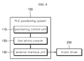
- Fig. 4 is a block diagram used to explain a PLC positioning system according to one embodiment of the present invention.
- a PLC positioning system 100 may be configured to include a positioning control unit 110, a fast photo coupler 120 and an external interface unit 130.
- the positioning control unit 110 is configured to divide axes into a first axis group and a second axis group, switch a task at a point of time of request for first axis group calculation of operation data calculation of the two groups, and preferentially perform position control calculation of the first group. Axes requiring a faster response belong to the first axis group. Axes requiring a slower response belong to the second axis group.
- the positioning control unit 110 may designate one axis for the first axis group and designate the remaining axes for the second axis group. Thus, calculation for the axis designated for the first axis group can be executed in preference to the remaining axes.
- the positioning control unit 110 may designate a plurality of axes for the first axis group and designate the remaining axes for the second axis group. Thus, calculation for the plurality of axes designated for the first axis group can be executed in preference to the remaining axes.
- the positioning control unit 110 may designate two axes for the first axis group and designate the remaining axes for the second axis group.
- calculation for the two axes designated for the first axis group can be executed in preference to the remaining axes.
- the two axes designated for the first axis group have the same priority.
- the increase number of axes designated for the first axis group increases, as the designated axes share the same priority, it is advantageous to set the number of axes designated for the first axis group to be as small as possible, preferably one.
- the positioning control unit 110 may generate a fast pulse train according to a pulse/direction or CW/CCW output mode and a high-active or low-active output level set by a user.
- the fast pulse train is transmitted to the outside through the fast photo coupler 120, which serves as an insulating transmission unit, in a state where the fast pulse train is electrically isolated from the outside.
- the fast pulse train is converted by the external interface unit 130 to a signal level of an open collector or line drive form suitable to an external motor driver 200.
- Fig. 5 is a flow chart used to explain a method of independent control period allocation of axes in the PLC positioning system according to one embodiment of the present invention.
- the positioning control unit 110 divides the axes into the first axis group having a first control period and the second axis group having a second control period and allocates different control periods for the axes (S11).
- the positioning control unit 110 uses task switching to allocate different control periods for the axes in such a manner that a shorter control period (the first control period) is allocated to an axis requiring a faster response and a longer period (the second control period) is allocated to an axis requiring a slower response.
- the positioning control unit 110 divides the axes into a servo-drive group requiring a shorter control period (the first axis group), such as an articulated robot or the like, and a servo-drive group requiring a longer control period (the second axis group), such as a conveyer belt or the like. Then, the positioning control unit 110 sets a position control calculation priority of the first axis group to be higher than a position control calculation priority of the second axis group.
- the first axis group such as an articulated robot or the like
- the second axis group such as a conveyer belt or the like.
- the positioning control unit 110 upon receiving a request for position control calculation of the first axis group during position control calculation of the second axis group, the positioning control unit 110 performs the position control calculation of the first axis group (S12). Then, after completion of the position control calculation of the first axis group, the positioning control unit 110 performs the position control calculation of the second axis group (S13). This process can guarantee the shorter control period of the first axis group instead of increasing the control period of the second axis group.
- the positioning control unit 110 may be implemented with MPU (Micro Process Unit). In this case, the positioning control unit 110 may perform independent control period allocation by using task switching using internal peripherals of the MPU.
- MPU Micro Process Unit
- RTOS Real Time Operating System
- the positioning control unit 110 can perform a process capable of flexible task switching at the time of occurrence of a timer interrupt of functions of the RTOS.
- the positioning control unit 110 stops ongoing calculation at the time of request of position calculation of an axis having a shorter control period during position calculation of an axis having a longer control period and preferentially performs the position calculation of the axis having the shorter control period. Upon completion of the position calculation of the axis having the shorter control period, the positioning control unit 110 resumes to perform the position calculation of the axis having the longer control period.
- the positioning control unit 110 provides two axis control rules as follows.
- a position control calculation routine for the axis having the shorter control period should be immediately performed.
- Typical RTOS uses a time tick or a call of API function with which a kernel works to switch a task.
- a kernel scheduler executes a task having the highest priority among tasks which are currently in a standby state.
- the time tick of the typical embedded RTOS is 10ms and, typically, a control period of about 1ms is basically provided for positioning control. This may cause more works performed for task switching than necessary, which may impose a burden on the system. Therefore, there is a need of an appropriate way for the positioning control unit 110 to perform task switching by utilizing only a multitasking technique on Non-RTOS.
- the task switching requires stack segmentation which may be arbitrarily implemented by a user with source codes.
- the positioning control unit 110 may employ a stack segmentation scheme which can use ISP (Interrupt Stack Pointer) and USP (User Stack Pointer).
- ISP Interrupt Stack Pointer
- USP User Stack Pointer
- the positioning control unit 110 can determine through control register manipulation whether to use an ISP area or a USP area for a current stack.
- Fig. 6 is a diagram illustrating a storage area of a current stack at a function call in the method of independent control period allocation of axes in the PLC positioning system according to one embodiment of the present invention.
- the positioning control unit 110 may receive a function call so as to perform a task of Func2 while performing a task of Func1.
- a push area and a pop area differ from each other depending on whether to use the ISP area or the USP area.
- the positioning control unit 110 pushes to the ISP area. Then, after completion of the task of Func2, when the task of Func2 is switched to the task of Func1, the positioning control unit 110 pops from the ISP area.
- the positioning control unit 110 pushes to the USP area. Then, after completion of the task of Func2, when the task of Func2 is switched to the task of Func1, the positioning control unit 110 pops from the USP area.
- Fig. 7 is a diagram illustrating a storage area of a current stack at an interrupt call in the method of independent control period allocation of axes in the PLC positioning system according to one embodiment of the present invention.
- the positioning control unit 110 performs the push and pop operation using the ISP area.
- the positioning control unit 110 pushes to the ISP area if Interrupt1 occurs while performing the task of Func1, and pushes to the ISP area if Interrupt2 occurs while performing the task of Interrupt1.
- the positioning control unit 110 pops from the ISP area.
- the positioning control unit 110 pops from the ISP area.
- the positioning control unit 110 uses the ISP area when there is no particular manipulation, and stores a current state in the ISP area when a function is called or an interrupt occurs. Even when the USP area is used, the positioning control unit 110 stores a current state in the USP area when a function is called, but may use the ISP area when an interrupt occurs.
- the positioning control unit 110 uses an interrupting process so that the ISP area of the two independent tasks can be used for an axis requiring a faster response and the USP area can be used for an axis requiring a slower response.
- the positioning control unit 110 calculates operation data based on the first control period for an axis using the ISP area and calculates operation data based on the second control period for an axis using the USP area.
- the first control period begins, position control calculation of the axis using the ISP area begins.
- the calculation of the axis using the ISP area has to be designated to such an extent that the calculation can be completed within a period shorter than the first control period, i.e., the calculation time is not longer than the first control period.
- Tasks are managed in such a way of performing calculation of the axis having the slower control period for a time left before the next control period begins after the calculation of the axis requiring the faster response is completed within the first control period.
- Fig. 8 is a diagram used to explain control calculation of a shorter control period and a longer control period according to one embodiment of the present invention.
- the positioning control unit 110 when beginning to perform operation data calculation, the positioning control unit 110 first begins to perform calculation of the first control period in the ISP area. When all control calculation to be performed within the first control period is finished, a system register of the positioning control unit 110 is used to perform stack switching to the USP area.
- the positioning control unit 110 stops the calculation in the USP area. Then, the positioning control unit 110 performs stack switching to the ISP region after storing a register state in a stack of the USP area. The positioning control unit 110 uses task switching to preferentially perform the position control calculation of the first control period. At this time, since a program pointer points the next step at a point of time when ISP is switched to USP, the calculation of the ISP area makes connection to the USP area.
- the positioning control unit 110 pushes all registers to the USP area. Then, after completion of an interrupt service routine, the positioning control unit 110 changes a return address to the first control period calculation area so as to return to the ISP area. Thereafter, the positioning control unit 110 switches the stack to perform the position control calculation of the first control period. When the position control calculation of the first control period is completed, the positioning control unit 110 pushes the general register, the state register and the program counter to the ISP area. Then, after the stack switching to the USP, the positioning control unit 110 resumes to perform the position control calculation of the second control period.
- Fig. 9 is a graph for explaining results of simulation on the method of independent control period allocation of axes in the PLC positioning system according to one embodiment of the present invention.
- Rx621 MPU (available from Renesas Company) was used to perform a simulation on the method of independent control period allocation of axes in the PLC positioning system according to one embodiment of the present invention.
- an On/Off signal output through a GPIO pin was measured with an oscilloscope.
- the GPIO pin connected to oscilloscope probe No. 3 (CH3) was switched on during first control period calculation and off after completion of the first control period calculation. For the second control period, this is equally applied to the GPIO pin connected to oscilloscope probe No. 2 (CH2).
- the first control period was designated with 1ms and the second control period was designated with 5ms. In other words, the second control period is repeated once while the first control period is repeated five times.
- the positioning control unit 110 uses second control period task switching to calculate the second control period (S22). Then, in the course of the second control period calculation, when a 1ms timer interrupt occurs at a point of time when the first control period begins, the positioning control unit 110 performs stack switching in order to perform the position control calculation of the first control period (S23). It can be confirmed from Fig. 9 that the remaining calculation of the second control period continues after completion of the first control period.
- the first control period (CH3) and the second control period (CH2) are configured to include a position control calculation execution interval and a margin interval for each axis. Even when the first control period is 1ms, only some of the entire period of 1ms is used as the control calculation execution interval in which the control calculation of the first control period is performed, but the other thereof is used as the margin interval. Since each of the control periods has the control calculation execution interval and the reserved margin interval, when the execution of the first control period is completed, the control calculation of the second control period is performed without waiting during the margin interval.
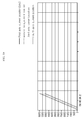
- Fig. 10 is a graph for explaining results of simulation on the method of independent control period allocation of axes in the PLC positioning system according to one embodiment of the present invention.
- the positioning control unit 110 controlling a plurality of axes allocates control periods for the axes independently and grants a calculation priority to an axis requiring a faster response. This can guarantee a response speed of the axis requiring the faster response even with the increased number of control axes.
Landscapes
- Engineering & Computer Science (AREA)
- Physics & Mathematics (AREA)
- General Physics & Mathematics (AREA)
- Automation & Control Theory (AREA)
- Human Computer Interaction (AREA)
- Manufacturing & Machinery (AREA)
- Programmable Controllers (AREA)
- Control Of Position Or Direction (AREA)
- Numerical Control (AREA)
Abstract
Description
- The present invention relates to a method of independent control period allocation of axes in a PLC positioning system. More specifically, the present invention relates to a method of independent control period allocation of axes in a PLC positioning system controlling a plurality of axes, in which the axes are divided into a first axis group requiring a faster response and a second axis group requiring a slower response and a task is switched at a point of time when position control calculation of the first axis group is requested, so as to perform the position control calculation of the first axis group in preference to position control calculation of the second axis group.
- A positioning function of a programmable logic controller (PLC) is a function of moving an object to a correct position by driving a motor with a fast pulse train output to a transistor output contact point of the PLC.
- With increase in the complexity of an automatic control system, a variety of applications for controlling a number of axes with a single controller have been developed. However, the existing direct servo-drive control based on a pulse or an analog signal has a limitation in the number of controllable servo-drives since input/output contact points are connected to servo-drives in a one-to-one correspondence.
- However, in recent years, beyond the above-mentioned method, other methods of using networking technologies to transmit a target position and speed to a number of servo-drives in real time have been utilized.
- As one example, an EtherCAT protocol may be used to provide instruction values and control data to 100 servo-axes every 100µs. However, it is difficult to calculate the movement of each of the 100 servo-axes every 100µs. Of course, an MPU with high performance may help to reduce calculation time, but cannot avoid any inherent limitation.
- A PLC positioning system calculates a pulse to be output every control period defined in unit time. The control period typically varies within a range from several hundred µm to several ten ms depending on makers and products. A frequency of a pulse output during a control period is constant and a speed (i.e., frequency) of a pulse to be output for the next control period is determined. Therefore, a shorter control period facilitates smoother motor control.
-
Figs. 1 and2 are diagrams used to explain a position control calculation method of a conventional PLC positioning system. - Referring to
Figs. 1 and2 , an amount of movement of an axis to be moved within a control period for each axis from the beginning of the control period of each interval is calculated (S1). In general, calculation from the first axis to the last axis (varying depending on products) is completed. Upon completing the calculation, a task waits for the remaining time of the corresponding control period or the remaining task required for control is proceeding (S2). During the next control period after completing the calculation, the amount of movement calculated in the previous control period is output to a servo-drive and, in the corresponding control period, an amount of movement during the second next control period of each axis is calculated (S3). The amount of movement calculated in the first control period is output during the second control period. The amount of movement calculated at this time is stored in an output buffer and is later output. - The above-described method has to allocate a control period in consideration of the maximum calculation time of all axes since the control periods of the axes are same. For example, if a system having 10 axes of the same kind whose calculation time is the maximum of 1ms is to be controlled, the control period has to be allocated to 10ms at minimum.
-
Fig. 3 is a diagram used to explain a case where a period of time taken to calculate all axes exceeds a control period in the conventional PLC positioning system. - Referring to
Fig. 3 , although an amount of movement of axes whose calculation is completed within the first control period including the first axis and the second axis is transferred to a servo-drive normally during the next control period, an axis whose calculation is not completed within the first control period (first interval) has no amount of movement to be output during the next control period. - Therefore, an nth axis has no actual output in the second interval. Accumulation of such an effect may cause an increasing position error. Therefore, if all axes are to be controlled with the same control period, position control calculation of all axes has to be completed with an allocated control period.
- However, the control period has an effect on responsiveness and flexibility of the control system. A longer control period leads to a slower response at an end-point as much, which has a direct effect on a yield of products.
- In addition, since a rate of speed change in an acceleration/deceleration interval increases, there is a high possibility of a failure due to a mechanical shock. Therefore, there is a need for a novel method for calculation of multiple axes.
- It is an aspect of the present invention to provide a method of independent control period allocation of axes in a PLC positioning system controlling a plurality of axes, in which the axes to be controlled are divided into a first axis group requiring a faster response and a second axis group requiring a slower response and a task is switched at a point of time when position control calculation of the first axis group is requested, so as to perform the position control calculation of the first axis group in preference to position control calculation of the second axis group, in order to flexibly control all the axes.
- The present invention is not limited to the above aspect and other aspects of the present invention will be clearly understood by those skilled in the art from the following description.
- In accordance with one aspect of the present invention, there is provided a method of independent control period allocation of axes in a PLC positioning system, including: dividing the axes into a first axis group having a first control period and a second axis group having a second control period and allocating different control periods for different axes; when position control calculation of the first axis group is requested during position control calculation of the second axis group, performing the position control calculation of the first axis group through task switching by an interrupt; and, after completing the position control calculation of the first axis group, resuming the position control calculation of the second axis group through task switching by an interrupt.
- The act of allocating different control periods for different axes may include designating a single axis to the first axis group.
- The act of allocating different control periods for different axes may include designating a plurality of axes to the first axis group.
- In the act of allocating different control periods for different axes, each of the first control period and the second control period may include a position control calculation execution interval and a margin interval for each of the axes.
- The act of resuming the position control calculation of the second axis group includes: when completing the position control calculation of the first axis group during the position control calculation execution interval of the first control period, performing task switching for the position control calculation of the second axis group; and resuming the position control calculation of the second axis group during the margin interval of the first axis group.
- The act of allocating different control periods for different axes may further include allocating a stack of an ISP area for axes in the first axis group and allocating a stack of a USP area for axes in the second axis group.
- The act of allocating different control periods for different axes may include designating the first control period so that calculation of an axis using the ISP area can be completed within the first control period.
- The act of performing the position control calculation of the first axis group may include: while performing the control calculation of the second control group, when a stack switching interrupt occurs at a point of time when the position control calculation of the first control period is requested, pushing all registers to the USP area, and, after completion of an interrupt service routine, changing a return address to a first control period calculation area so as to return to the ISP area, and the act of resuming the position control calculation of the second axis group may include: when completing the control calculation of the first control period, pushing a general register, a state register and a program counter to the ISP area and, after stack switching to the USP area, resuming to perform the control calculation of the second control period.
- According to the present invention, in a method of independent control period allocation of axes in a PLC positioning system controlling a plurality of axes, beyond the existing way of applying control periods collectively, it is possible to divide the axes into a first axis group (requiring a faster response) and a second axis group (requiring a slower response) and switch a task at a point of time when position control calculation of the first axis group is requested during calculation of operation data of the two axis groups, so as to perform the position control calculation of the first axis group in preference to position control calculation of the second axis group, in order to flexibly control all the axes.
- According to the present invention, since a calculation priority is granted to an axis requiring a faster response, it is possible to guarantee a response speed of the axis requiring the faster response even with the increased number of control axes.
- In the industrial fields, there are axes which are more sensitive to a response speed and axial synchronization, as in articulated robots and the like, and axes which are less sensitive to a response speed and axial synchronization, as in conveyer belts and the like. According to the present invention, by allocating axes controlling the articulated robots and the like to the first axis group and allocating axes controlling the conveyer belts and the like to the second axis group, it is possible to flexibly control a servo-drive even in a large-scaled system.
-
-
Fig. 1 is a diagram used to explain a position control calculation method of a conventional PLC positioning system. -
Fig. 2 is a flow chart used to explain the position control calculation method of the conventional PLC positioning system. -
Fig. 3 is a diagram used to explain a case where a period of time taken to calculate all axes exceeds a control period in the conventional PLC positioning system. -
Fig. 4 is a block diagram used to explain a PLC positioning system according to one embodiment of the present invention. -
Fig. 5 is a flow chart used to explain a method of independent control period allocation of axes in the PLC positioning system according to one embodiment of the present invention. -
Fig. 6 is a diagram illustrating a storage area of a current stack at a function call in the method of independent control period allocation of axes in the PLC positioning system according to one embodiment of the present invention. -
Fig. 7 is a diagram illustrating a storage area of a current stack at an interrupt call in the method of independent control period allocation of axes in the PLC positioning system according to one embodiment of the present invention. -
Fig. 8 is a diagram used to explain control calculation of a shorter control period and a longer control period according to one embodiment of the present invention. -
Fig. 9 is a graph for explaining results of simulation on the method of independent control period allocation of axes in the PLC positioning system according to one embodiment of the present invention. -
Fig. 10 is a graph for explaining results of simulation on the method of independent control period allocation of axes in the PLC positioning system according to one embodiment of the present invention. - Hereinafter, embodiments of the present invention will be described in detail with reference to the accompanying drawings. It should be understood that the present invention is not limited to the following embodiments, and that the embodiments are provided for illustrative purposes only. The scope of the invention should be defined only by the accompanying claims and equivalents thereof.
-
Fig. 4 is a block diagram used to explain a PLC positioning system according to one embodiment of the present invention. - Referring to
Fig. 4 , aPLC positioning system 100 according to one embodiment of the present invention may be configured to include apositioning control unit 110, afast photo coupler 120 and anexternal interface unit 130. - The
positioning control unit 110 is configured to divide axes into a first axis group and a second axis group, switch a task at a point of time of request for first axis group calculation of operation data calculation of the two groups, and preferentially perform position control calculation of the first group. Axes requiring a faster response belong to the first axis group. Axes requiring a slower response belong to the second axis group. - The
positioning control unit 110 may designate one axis for the first axis group and designate the remaining axes for the second axis group. Thus, calculation for the axis designated for the first axis group can be executed in preference to the remaining axes. - The
positioning control unit 110 may designate a plurality of axes for the first axis group and designate the remaining axes for the second axis group. Thus, calculation for the plurality of axes designated for the first axis group can be executed in preference to the remaining axes. - For example, the
positioning control unit 110 may designate two axes for the first axis group and designate the remaining axes for the second axis group. Thus, calculation for the two axes designated for the first axis group can be executed in preference to the remaining axes. At this time, the two axes designated for the first axis group have the same priority. With the increase number of axes designated for the first axis group increases, as the designated axes share the same priority, it is advantageous to set the number of axes designated for the first axis group to be as small as possible, preferably one. - The
positioning control unit 110 may generate a fast pulse train according to a pulse/direction or CW/CCW output mode and a high-active or low-active output level set by a user. The fast pulse train is transmitted to the outside through thefast photo coupler 120, which serves as an insulating transmission unit, in a state where the fast pulse train is electrically isolated from the outside. The fast pulse train is converted by theexternal interface unit 130 to a signal level of an open collector or line drive form suitable to anexternal motor driver 200. -
Fig. 5 is a flow chart used to explain a method of independent control period allocation of axes in the PLC positioning system according to one embodiment of the present invention. - Referring to
Fig. 5 , thepositioning control unit 110 divides the axes into the first axis group having a first control period and the second axis group having a second control period and allocates different control periods for the axes (S11). - That is, the
positioning control unit 110 uses task switching to allocate different control periods for the axes in such a manner that a shorter control period (the first control period) is allocated to an axis requiring a faster response and a longer period (the second control period) is allocated to an axis requiring a slower response. - For example, the
positioning control unit 110 divides the axes into a servo-drive group requiring a shorter control period (the first axis group), such as an articulated robot or the like, and a servo-drive group requiring a longer control period (the second axis group), such as a conveyer belt or the like. Then, thepositioning control unit 110 sets a position control calculation priority of the first axis group to be higher than a position control calculation priority of the second axis group. - That is, upon receiving a request for position control calculation of the first axis group during position control calculation of the second axis group, the
positioning control unit 110 performs the position control calculation of the first axis group (S12). Then, after completion of the position control calculation of the first axis group, thepositioning control unit 110 performs the position control calculation of the second axis group (S13). This process can guarantee the shorter control period of the first axis group instead of increasing the control period of the second axis group. - The
positioning control unit 110 may be implemented with MPU (Micro Process Unit). In this case, thepositioning control unit 110 may perform independent control period allocation by using task switching using internal peripherals of the MPU. - If RTOS (Real Time Operating System) is used to implement the task switching technique, this may cause loads having much necessary periodic/aperiodic scheduling, which may lead to waste of MPU resources.
- Therefore, the
positioning control unit 110 can perform a process capable of flexible task switching at the time of occurrence of a timer interrupt of functions of the RTOS. - That is, the
positioning control unit 110 stops ongoing calculation at the time of request of position calculation of an axis having a shorter control period during position calculation of an axis having a longer control period and preferentially performs the position calculation of the axis having the shorter control period. Upon completion of the position calculation of the axis having the shorter control period, thepositioning control unit 110 resumes to perform the position calculation of the axis having the longer control period. - To this end, the
positioning control unit 110 provides two axis control rules as follows. - First, at the time of request of position calculation of an axis having a shorter control period during position calculation of an axis having a longer control period, a position control calculation routine for the axis having the shorter control period should be immediately performed.
- Second, upon completion of the position calculation of the axis having the shorter control period, the position control calculation of the axis having the longer control period should be resumed.
- The task switching technique is required to flexibly implement position control calculation of axes having different control periods. Typical RTOS uses a time tick or a call of API function with which a kernel works to switch a task. When a kernel function is called, a kernel scheduler executes a task having the highest priority among tasks which are currently in a standby state.
- However, the time tick of the typical embedded RTOS is 10ms and, typically, a control period of about 1ms is basically provided for positioning control. This may cause more works performed for task switching than necessary, which may impose a burden on the system. Therefore, there is a need of an appropriate way for the
positioning control unit 110 to perform task switching by utilizing only a multitasking technique on Non-RTOS. - The task switching requires stack segmentation which may be arbitrarily implemented by a user with source codes. For example, the
positioning control unit 110 may employ a stack segmentation scheme which can use ISP (Interrupt Stack Pointer) and USP (User Stack Pointer). Thepositioning control unit 110 can determine through control register manipulation whether to use an ISP area or a USP area for a current stack. -
Fig. 6 is a diagram illustrating a storage area of a current stack at a function call in the method of independent control period allocation of axes in the PLC positioning system according to one embodiment of the present invention. - Referring to
Fig. 6 , thepositioning control unit 110 may receive a function call so as to perform a task of Func2 while performing a task of Func1. At this time, a push area and a pop area differ from each other depending on whether to use the ISP area or the USP area. - When the ISP area is used, if there is a function call for performing the task of Func2 while performing the task of Func1, the
positioning control unit 110 pushes to the ISP area. Then, after completion of the task of Func2, when the task of Func2 is switched to the task of Func1, thepositioning control unit 110 pops from the ISP area. - On the other hand, when the USP area is used, if there is a function call for performing the task of Func2 while performing the task of Func1, the
positioning control unit 110 pushes to the USP area. Then, after completion of the task of Func2, when the task of Func2 is switched to the task of Func1, thepositioning control unit 110 pops from the USP area. -
Fig. 7 is a diagram illustrating a storage area of a current stack at an interrupt call in the method of independent control period allocation of axes in the PLC positioning system according to one embodiment of the present invention. - Referring to
Fig. 7 , if an interrupt occurs in all cases where the ISP area or the USP area is used, thepositioning control unit 110 performs the push and pop operation using the ISP area. - For example, the
positioning control unit 110 pushes to the ISP area if Interrupt1 occurs while performing the task of Func1, and pushes to the ISP area if Interrupt2 occurs while performing the task of Interrupt1. - Again, after completion of the task of Interrupt2, when the task of Interrupt2 is switched to the task of Interrupt1, the
positioning control unit 110 pops from the ISP area. In addition, after completion of the task of Interrupt1, when the task of Interrupt1 is switched to the task of Func1, thepositioning control unit 110 pops from the ISP area. - In this way, the
positioning control unit 110 uses the ISP area when there is no particular manipulation, and stores a current state in the ISP area when a function is called or an interrupt occurs. Even when the USP area is used, thepositioning control unit 110 stores a current state in the USP area when a function is called, but may use the ISP area when an interrupt occurs. - Accordingly, the
positioning control unit 110 uses an interrupting process so that the ISP area of the two independent tasks can be used for an axis requiring a faster response and the USP area can be used for an axis requiring a slower response. - For convenience, it is here assumed that the faster control period is a first control period and the slower control period is a second control period. Accordingly, the
positioning control unit 110 calculates operation data based on the first control period for an axis using the ISP area and calculates operation data based on the second control period for an axis using the USP area. When the first control period begins, position control calculation of the axis using the ISP area begins. - It should be here noted that the calculation of the axis using the ISP area has to be designated to such an extent that the calculation can be completed within a period shorter than the first control period, i.e., the calculation time is not longer than the first control period. Tasks are managed in such a way of performing calculation of the axis having the slower control period for a time left before the next control period begins after the calculation of the axis requiring the faster response is completed within the first control period.
-
Fig. 8 is a diagram used to explain control calculation of a shorter control period and a longer control period according to one embodiment of the present invention. - Referring to
Fig. 8 , when beginning to perform operation data calculation, thepositioning control unit 110 first begins to perform calculation of the first control period in the ISP area. When all control calculation to be performed within the first control period is finished, a system register of thepositioning control unit 110 is used to perform stack switching to the USP area. - When a timer interrupt for position control calculation of the first control period occurs in the course of calculation of the second control period in the USP period, the
positioning control unit 110 stops the calculation in the USP area. Then, thepositioning control unit 110 performs stack switching to the ISP region after storing a register state in a stack of the USP area. Thepositioning control unit 110 uses task switching to preferentially perform the position control calculation of the first control period. At this time, since a program pointer points the next step at a point of time when ISP is switched to USP, the calculation of the ISP area makes connection to the USP area. - That is, while using the timer interrupt to calculate the second control period, when a stack switching interrupt (1ms) occurs at a point of time when the position control calculation of the first control period is requested, the
positioning control unit 110 pushes all registers to the USP area. Then, after completion of an interrupt service routine, thepositioning control unit 110 changes a return address to the first control period calculation area so as to return to the ISP area. Thereafter, thepositioning control unit 110 switches the stack to perform the position control calculation of the first control period. When the position control calculation of the first control period is completed, thepositioning control unit 110 pushes the general register, the state register and the program counter to the ISP area. Then, after the stack switching to the USP, thepositioning control unit 110 resumes to perform the position control calculation of the second control period. -
Fig. 9 is a graph for explaining results of simulation on the method of independent control period allocation of axes in the PLC positioning system according to one embodiment of the present invention. - Referring to
Fig. 9 , Rx621 MPU (available from Renesas Company) was used to perform a simulation on the method of independent control period allocation of axes in the PLC positioning system according to one embodiment of the present invention. In order to check whether an area where a program is being executed is an ISP area or a USP area, an On/Off signal output through a GPIO pin was measured with an oscilloscope. The GPIO pin connected to oscilloscope probe No. 3 (CH3) was switched on during first control period calculation and off after completion of the first control period calculation. For the second control period, this is equally applied to the GPIO pin connected to oscilloscope probe No. 2 (CH2). - The first control period was designated with 1ms and the second control period was designated with 5ms. In other words, the second control period is repeated once while the first control period is repeated five times.
- In this way, it was confirmed that operation data calculations of two groups having different control periods were performed over time as follows.
- As can be seen from
Fig. 9 , when completing the first control period calculation (S21), thepositioning control unit 110 uses second control period task switching to calculate the second control period (S22). Then, in the course of the second control period calculation, when a 1ms timer interrupt occurs at a point of time when the first control period begins, thepositioning control unit 110 performs stack switching in order to perform the position control calculation of the first control period (S23). It can be confirmed fromFig. 9 that the remaining calculation of the second control period continues after completion of the first control period. - It is here noted that the first control period (CH3) and the second control period (CH2) are configured to include a position control calculation execution interval and a margin interval for each axis. Even when the first control period is 1ms, only some of the entire period of 1ms is used as the control calculation execution interval in which the control calculation of the first control period is performed, but the other thereof is used as the margin interval. Since each of the control periods has the control calculation execution interval and the reserved margin interval, when the execution of the first control period is completed, the control calculation of the second control period is performed without waiting during the margin interval.
-
Fig. 10 is a graph for explaining results of simulation on the method of independent control period allocation of axes in the PLC positioning system according to one embodiment of the present invention. - Results of calculation of first and second axes with the first control period and calculation of third and fourth axes with the second control period are shown in
Fig. 10 . It can be confirmed fromFig. 10 that the axes move at the same speed and generate the same profile. - According to the present invention, the
positioning control unit 110 controlling a plurality of axes allocates control periods for the axes independently and grants a calculation priority to an axis requiring a faster response. This can guarantee a response speed of the axis requiring the faster response even with the increased number of control axes. - In the industrial fields, there are axes which are more sensitive to a response speed and axial synchronization, as in articulated robots and the like, and axes which are less sensitive to a response speed and axial synchronization, as in conveyer belts and the like. According to the present invention, by allocating axes controlling the articulated robots and the like to the first axis group and allocating axes controlling the conveyer belts and the like to the second axis group, it is possible to flexibly control a servo-drive even in a large-scaled system.
- While certain embodiments have been described, these embodiments have been presented by way of example only, and are not intended to limit the scope of the disclosures. Indeed, the novel methods and apparatuses described herein may be embodied in a variety of other forms; furthermore, various omissions, substitutions and changes in the form of the embodiments described herein may be made without departing from the spirit of the disclosures. The accompanying claims and their equivalents are intended to cover such forms or modifications as would fall within the scope and spirit of the disclosures.
Claims (8)
- A method of independent control period allocation of axes in a PLC positioning system (100), comprising:dividing the axes into a first axis group having a first control period and a second axis group having a second control period and allocating different control periods for different axes;when position control calculation of the first axis group is requested during position control calculation of the second axis group, performing the position control calculation of the first axis group through task switching by an interrupt; andafter completing the position control calculation of the first axis group, resuming the position control calculation of the second axis group through task switching by an interrupt.
- The method according to claim 1, wherein the act of allocating different control periods for different axes includes designating a single axis to the first axis group.
- The method according to claim 1, wherein the act of allocating different control periods for different axes includes designating a plurality of axes to the first axis group.
- The method according to claim 1, wherein, in the act of allocating different control periods for different axes, each of the first control period and the second control period includes a position control calculation execution interval and a margin interval for each of the axes.
- The method according to claim 4, wherein the act of resuming the position control calculation of the second axis group includes:when completing the position control calculation of the first axis group during the position control calculation execution interval of the first control period, performing task switching for the position control calculation of the second axis group; andresuming the position control calculation of the second axis group during the margin interval of the first axis group.
- The method according to claim 1, wherein the act of allocating different control periods for different axes further includes allocating a stack of an ISP area for axes in the first axis group and allocating a stack of a USP area for axes in the second axis group.
- The method according to claim 6, wherein the act of allocating different control periods for different axes includes designating the first control period so that calculation of an axis using the ISP area can be completed within the first control period.
- The method according to claim 6, wherein the act of performing the position control calculation of the first axis group includes: while performing the control calculation of the second control group, when a stack switching interrupt occurs at a point of time when the position control calculation of the first control period is requested, pushing all registers to the USP area, and, after completion of an interrupt service routine, changing a return address to a first control period calculation area so as to return to the ISP area, and
wherein the act of resuming the position control calculation of the second axis group includes: when completing the control calculation of the first control period, pushing a general register, a state register and a program counter to the ISP area and, after stack switching to the USP area, resuming to perform the control calculation of the second control period.
Applications Claiming Priority (1)
| Application Number | Priority Date | Filing Date | Title |
|---|---|---|---|
| KR1020150146342A KR102079499B1 (en) | 2015-10-20 | 2015-10-20 | A method of independent control period allocation of axis in the PLC positioning system |
Publications (2)
| Publication Number | Publication Date |
|---|---|
| EP3159761A1 true EP3159761A1 (en) | 2017-04-26 |
| EP3159761B1 EP3159761B1 (en) | 2019-08-21 |
Family
ID=57003318
Family Applications (1)
| Application Number | Title | Priority Date | Filing Date |
|---|---|---|---|
| EP16186659.5A Not-in-force EP3159761B1 (en) | 2015-10-20 | 2016-08-31 | A method of independent control period allocation of axis in the plc positioning system |
Country Status (6)
| Country | Link |
|---|---|
| US (1) | US10394213B2 (en) |
| EP (1) | EP3159761B1 (en) |
| JP (1) | JP6429842B2 (en) |
| KR (1) | KR102079499B1 (en) |
| CN (1) | CN106843121B (en) |
| ES (1) | ES2752879T3 (en) |
Families Citing this family (3)
| Publication number | Priority date | Publication date | Assignee | Title |
|---|---|---|---|---|
| JP6520545B2 (en) * | 2015-08-10 | 2019-05-29 | オムロン株式会社 | Support device and support program |
| KR102115310B1 (en) * | 2018-04-25 | 2020-05-26 | 엘에스일렉트릭(주) | Position control apparatus based on programmable logic controller |
| KR102132857B1 (en) * | 2018-05-03 | 2020-07-10 | 엘에스일렉트릭(주) | Method for controlling motor driving |
Citations (2)
| Publication number | Priority date | Publication date | Assignee | Title |
|---|---|---|---|---|
| EP0347467A1 (en) * | 1987-12-10 | 1989-12-27 | Fanuc Ltd. | Cnc control system |
| WO1996033450A1 (en) * | 1995-04-19 | 1996-10-24 | Siemens Aktiengesellschaft | Process for operating a numerical control with critical-time and non-critical-time processes in a real time system |
Family Cites Families (53)
| Publication number | Priority date | Publication date | Assignee | Title |
|---|---|---|---|---|
| US4319338A (en) * | 1979-12-12 | 1982-03-09 | Allen-Bradley Company | Industrial communications network with mastership determined by need |
| US4514814A (en) * | 1982-09-07 | 1985-04-30 | General Electric Company | Multi-processor axis control |
| JPH0766284B2 (en) * | 1984-07-23 | 1995-07-19 | 日産自動車株式会社 | Programmable logic controller |
| AU1359892A (en) * | 1991-02-15 | 1992-09-15 | Incontrol, Inc. | Computer control system for generating geometric designs |
| US5453933A (en) * | 1993-09-08 | 1995-09-26 | Hurco Companies, Inc. | CNC control system |
| JPH0851796A (en) * | 1994-06-01 | 1996-02-20 | Minolta Co Ltd | Motor control mechanism |
| DE19500957A1 (en) * | 1994-07-19 | 1996-01-25 | Bosch Gmbh Robert | Procedures for the control of technical processes or processes |
| US6466962B2 (en) * | 1995-06-07 | 2002-10-15 | International Business Machines Corporation | System and method for supporting real-time computing within general purpose operating systems |
| GB9825102D0 (en) * | 1998-11-16 | 1999-01-13 | Insignia Solutions Plc | Computer system |
| WO2001002918A1 (en) | 1999-07-06 | 2001-01-11 | Mitsubishi Denki Kabushiki Kaisha | Drive control system |
| US6594541B1 (en) * | 2000-01-10 | 2003-07-15 | Siemens Aktiengesellschaft | Universal motion control |
| US20020198970A1 (en) * | 2001-04-27 | 2002-12-26 | Shunji Kuwa | Programmable controller system |
| DE10144788A1 (en) * | 2001-09-11 | 2003-04-30 | Siemens Ag | Process data recording method e.g. for robot, involves storing process data in data buffer memory having first-in-first out characteristic |
| US7076332B2 (en) * | 2002-01-18 | 2006-07-11 | National Instruments Corporation | System and method for invoking execution of a sequence of operations that includes motion control, machine vision, and data acquisition (DAQ) functionality |
| ITFI20020040A1 (en) * | 2002-03-08 | 2003-09-08 | Bedogni S R L | EQUIPMENT FOR HANDLING TOOLS FOR THE PRODUCTION OF GLASS, CRYSTAL AND SIMILAR ITEMS |
| JP3922070B2 (en) * | 2002-03-29 | 2007-05-30 | 株式会社デンソー | Distributed control method and apparatus |
| KR20040071921A (en) | 2003-02-07 | 2004-08-16 | 삼성전자주식회사 | Multi-axis servo drive system |
| US20060153008A1 (en) * | 2003-02-12 | 2006-07-13 | Toshiyuki Miyamatsu | Control device and control method capable of external synchronization |
| JP3680064B2 (en) * | 2003-04-21 | 2005-08-10 | ファナック株式会社 | Numerical controller |
| JP2006187826A (en) | 2005-01-05 | 2006-07-20 | Kawasaki Heavy Ind Ltd | Robot controller |
| JP2007140655A (en) * | 2005-11-15 | 2007-06-07 | Yaskawa Electric Corp | Motion controller |
| US7565654B2 (en) * | 2006-01-10 | 2009-07-21 | National Instruments Corporation | Programmatic control of tasks in a programmable logic controller |
| US7424563B2 (en) * | 2006-02-24 | 2008-09-09 | Qualcomm Incorporated | Two-level interrupt service routine |
| JP2009059310A (en) * | 2007-09-03 | 2009-03-19 | Panasonic Corp | Program controller |
| US8334669B2 (en) | 2007-10-31 | 2012-12-18 | Thk Co., Ltd. | Multi-axis driver control method, multi-axis driver and multi-axis drive control system having the same |
| JP4382123B2 (en) * | 2007-12-13 | 2009-12-09 | ファナック株式会社 | Numerical control device having control mode switching function |
| DE102009047024A1 (en) * | 2009-11-23 | 2011-05-26 | Beckhoff Automation Gmbh | Parallelized program control |
| DE102009055752A1 (en) * | 2009-11-25 | 2011-05-26 | Robert Bosch Gmbh | A method of enabling sequential non-blocking processing of instructions in concurrent tasks in a controller |
| JP5246186B2 (en) * | 2010-03-15 | 2013-07-24 | オムロン株式会社 | Controller support device, control program simulation method, controller support program, and computer-readable storage medium storing controller support program |
| JP5120424B2 (en) * | 2010-07-27 | 2013-01-16 | 横河電機株式会社 | Sequence control device |
| JP5301041B2 (en) * | 2010-12-16 | 2013-09-25 | 三菱電機株式会社 | Sequencer system and control method thereof |
| CN202094830U (en) * | 2011-01-25 | 2011-12-28 | 南京雪曼机电科技有限公司 | Multiaxial synchronizing servo drive system |
| CN102130640B (en) * | 2011-01-25 | 2013-04-10 | 南京雪曼机电科技有限公司 | Multishaft synchronous servo driving system and synchronous control method thereof |
| WO2012104899A1 (en) * | 2011-01-31 | 2012-08-09 | トヨタ自動車株式会社 | Safety control device and safety control method |
| JP4995976B1 (en) * | 2011-02-08 | 2012-08-08 | ファナック株式会社 | Numerical control device that performs in-position check of rotating shaft |
| JP4877423B1 (en) * | 2011-03-15 | 2012-02-15 | オムロン株式会社 | PLC CPU unit, PLC system program, and recording medium storing PLC system program |
| JP4752984B1 (en) * | 2011-03-15 | 2011-08-17 | オムロン株式会社 | PLC CPU unit, PLC system program, and recording medium storing PLC system program |
| US8706262B2 (en) * | 2011-03-15 | 2014-04-22 | Omron Corporation | CPU unit of PLC, system program for PLC, and recording medium storing system program for PLC |
| JP4894961B1 (en) * | 2011-03-15 | 2012-03-14 | オムロン株式会社 | PLC CPU unit, PLC system program, and recording medium storing PLC system program |
| US8799880B2 (en) * | 2011-04-08 | 2014-08-05 | Siemens Aktiengesellschaft | Parallelization of PLC programs for operation in multi-processor environments |
| JP5803337B2 (en) * | 2011-06-28 | 2015-11-04 | オムロン株式会社 | Synchronization control device, synchronization control method, synchronization control program, and computer-readable recording medium recording the synchronization control program |
| WO2013010159A1 (en) * | 2011-07-14 | 2013-01-17 | Siemens Corporation | Reducing the scan cycle time of control applications through multi-core execution of user programs |
| JP5099251B1 (en) * | 2011-07-15 | 2012-12-19 | オムロン株式会社 | PLC CPU unit, PLC system program, recording medium storing PLC system program, PLC system, PLC support device, PLC support program, and recording medium storing PLC support program |
| KR101271854B1 (en) | 2011-08-31 | 2013-06-07 | 숭실대학교산학협력단 | Apparatus and method for scheduling task period |
| CN103123476B (en) * | 2011-11-18 | 2015-10-28 | 中国科学院沈阳计算技术研究所有限公司 | A kind of single servo motor drives the control method for numerical control system of gang tool |
| FR2997773B1 (en) * | 2012-11-06 | 2016-02-05 | Centre Nat Rech Scient | METHOD OF SCHEDULING WITH DELAY CONSTRAINTS, ESPECIALLY IN LINUX, REALIZED IN USER SPACE. |
| DE112012001007T5 (en) | 2012-12-10 | 2014-09-11 | Mitsubishi Electric Corp. | Multi-axis control system setting / Justierfunktionsunterstützungsvorrichtung |
| CN103870327A (en) * | 2012-12-18 | 2014-06-18 | 华为技术有限公司 | Real-time multitask scheduling method and device |
| FR3004825B1 (en) * | 2013-04-19 | 2015-04-24 | Krono Safe | TIME ALLOCATION METHOD OF TASKS FOR REAL-TIME DETERMINISTIC ERROR RECOVERY |
| KR20150074392A (en) | 2013-12-24 | 2015-07-02 | 엘에스산전 주식회사 | Method for setting control period of the positioning system |
| JP6626240B2 (en) | 2014-03-13 | 2019-12-25 | オムロン株式会社 | controller |
| KR102338849B1 (en) * | 2014-04-01 | 2021-12-14 | 삼성전자주식회사 | Method and system for providing stack memory management in real-time operating systems |
| JP6203691B2 (en) * | 2014-08-29 | 2017-09-27 | ファナック株式会社 | Numerical control device that can execute distributed axis control processing for multiple axes |
-
2015
- 2015-10-20 KR KR1020150146342A patent/KR102079499B1/en not_active Expired - Fee Related
-
2016
- 2016-08-31 EP EP16186659.5A patent/EP3159761B1/en not_active Not-in-force
- 2016-08-31 ES ES16186659T patent/ES2752879T3/en active Active
- 2016-09-21 CN CN201610839540.8A patent/CN106843121B/en not_active Expired - Fee Related
- 2016-10-13 US US15/293,215 patent/US10394213B2/en not_active Expired - Fee Related
- 2016-10-17 JP JP2016203273A patent/JP6429842B2/en not_active Expired - Fee Related
Patent Citations (2)
| Publication number | Priority date | Publication date | Assignee | Title |
|---|---|---|---|---|
| EP0347467A1 (en) * | 1987-12-10 | 1989-12-27 | Fanuc Ltd. | Cnc control system |
| WO1996033450A1 (en) * | 1995-04-19 | 1996-10-24 | Siemens Aktiengesellschaft | Process for operating a numerical control with critical-time and non-critical-time processes in a real time system |
Also Published As
| Publication number | Publication date |
|---|---|
| US10394213B2 (en) | 2019-08-27 |
| CN106843121B (en) | 2019-05-17 |
| CN106843121A (en) | 2017-06-13 |
| ES2752879T3 (en) | 2020-04-06 |
| US20170108845A1 (en) | 2017-04-20 |
| KR102079499B1 (en) | 2020-02-21 |
| JP2017079060A (en) | 2017-04-27 |
| KR20170046256A (en) | 2017-05-02 |
| JP6429842B2 (en) | 2018-11-28 |
| EP3159761B1 (en) | 2019-08-21 |
Similar Documents
| Publication | Publication Date | Title |
|---|---|---|
| CN109557890B (en) | Control device | |
| US9618922B2 (en) | CPU of PLC, system program for PLC, and recording medium storing system program for PLC | |
| US10274936B2 (en) | Control apparatus | |
| US10139799B2 (en) | Controller to modify an execution condition during program execution | |
| US10162673B2 (en) | Controller preventing communication collisions between parallel control programs | |
| EP3159761B1 (en) | A method of independent control period allocation of axis in the plc positioning system | |
| CN110192159B (en) | Control device | |
| US10877803B2 (en) | Control apparatus, control method and non-transitory storage medium | |
| EP3876044A1 (en) | Synchronization control device, synchronization control system, synchronization control method, and simulation device | |
| US20170132030A1 (en) | Virtual machine system, control method thereof, and control program recording medium thereof | |
| WO2017203776A1 (en) | Motor drive system, motor control system, and self-propelled robot | |
| US11663150B2 (en) | Fault tolerant system | |
| US20160048156A1 (en) | Automation device and method for reducing jitter | |
| US20230069599A1 (en) | Time-division multiplexing communication system and recording medium | |
| CN117742200A (en) | Equipment motion control system, method and equipment | |
| US9905264B2 (en) | Servo control system having function of switching learning memory | |
| JP2010160713A (en) | Field control apparatus and field control method | |
| US20230401090A1 (en) | Control device, control method, and non-transitory computer readable medium | |
| WO2023230909A1 (en) | Scheduling method and related equipment | |
| CN114756342A (en) | I2C communication simulation method and system | |
| Wang et al. | Real Time Multi-tasking Applying to AC800M Controller | |
| KR20150130019A (en) | Method for Setting Communication Period and Control Period of Network Based Motion Controller |
Legal Events
| Date | Code | Title | Description |
|---|---|---|---|
| PUAI | Public reference made under article 153(3) epc to a published international application that has entered the european phase |
Free format text: ORIGINAL CODE: 0009012 |
|
| STAA | Information on the status of an ep patent application or granted ep patent |
Free format text: STATUS: THE APPLICATION HAS BEEN PUBLISHED |
|
| AK | Designated contracting states |
Kind code of ref document: A1 Designated state(s): AL AT BE BG CH CY CZ DE DK EE ES FI FR GB GR HR HU IE IS IT LI LT LU LV MC MK MT NL NO PL PT RO RS SE SI SK SM TR |
|
| AX | Request for extension of the european patent |
Extension state: BA ME |
|
| STAA | Information on the status of an ep patent application or granted ep patent |
Free format text: STATUS: REQUEST FOR EXAMINATION WAS MADE |
|
| 17P | Request for examination filed |
Effective date: 20171023 |
|
| RBV | Designated contracting states (corrected) |
Designated state(s): AL AT BE BG CH CY CZ DE DK EE ES FI FR GB GR HR HU IE IS IT LI LT LU LV MC MK MT NL NO PL PT RO RS SE SI SK SM TR |
|
| REG | Reference to a national code |
Ref country code: DE Ref legal event code: R079 Ref document number: 602016018878 Country of ref document: DE Free format text: PREVIOUS MAIN CLASS: G05B0019414000 Ipc: G05B0019050000 |
|
| RIC1 | Information provided on ipc code assigned before grant |
Ipc: G05B 19/414 20060101ALI20190304BHEP Ipc: G05B 19/29 20060101ALI20190304BHEP Ipc: G05B 19/05 20060101AFI20190304BHEP |
|
| GRAP | Despatch of communication of intention to grant a patent |
Free format text: ORIGINAL CODE: EPIDOSNIGR1 |
|
| STAA | Information on the status of an ep patent application or granted ep patent |
Free format text: STATUS: GRANT OF PATENT IS INTENDED |
|
| INTG | Intention to grant announced |
Effective date: 20190416 |
|
| GRAS | Grant fee paid |
Free format text: ORIGINAL CODE: EPIDOSNIGR3 |
|
| GRAA | (expected) grant |
Free format text: ORIGINAL CODE: 0009210 |
|
| STAA | Information on the status of an ep patent application or granted ep patent |
Free format text: STATUS: THE PATENT HAS BEEN GRANTED |
|
| AK | Designated contracting states |
Kind code of ref document: B1 Designated state(s): AL AT BE BG CH CY CZ DE DK EE ES FI FR GB GR HR HU IE IS IT LI LT LU LV MC MK MT NL NO PL PT RO RS SE SI SK SM TR |
|
| REG | Reference to a national code |
Ref country code: GB Ref legal event code: FG4D |
|
| REG | Reference to a national code |
Ref country code: CH Ref legal event code: EP |
|
| REG | Reference to a national code |
Ref country code: DE Ref legal event code: R096 Ref document number: 602016018878 Country of ref document: DE |
|
| REG | Reference to a national code |
Ref country code: AT Ref legal event code: REF Ref document number: 1170453 Country of ref document: AT Kind code of ref document: T Effective date: 20190915 |
|
| REG | Reference to a national code |
Ref country code: IE Ref legal event code: FG4D |
|
| REG | Reference to a national code |
Ref country code: LT Ref legal event code: MG4D |
|
| REG | Reference to a national code |
Ref country code: NL Ref legal event code: MP Effective date: 20190821 |
|
| PG25 | Lapsed in a contracting state [announced via postgrant information from national office to epo] |
Ref country code: PT Free format text: LAPSE BECAUSE OF FAILURE TO SUBMIT A TRANSLATION OF THE DESCRIPTION OR TO PAY THE FEE WITHIN THE PRESCRIBED TIME-LIMIT Effective date: 20191223 Ref country code: NO Free format text: LAPSE BECAUSE OF FAILURE TO SUBMIT A TRANSLATION OF THE DESCRIPTION OR TO PAY THE FEE WITHIN THE PRESCRIBED TIME-LIMIT Effective date: 20191121 Ref country code: NL Free format text: LAPSE BECAUSE OF FAILURE TO SUBMIT A TRANSLATION OF THE DESCRIPTION OR TO PAY THE FEE WITHIN THE PRESCRIBED TIME-LIMIT Effective date: 20190821 Ref country code: LT Free format text: LAPSE BECAUSE OF FAILURE TO SUBMIT A TRANSLATION OF THE DESCRIPTION OR TO PAY THE FEE WITHIN THE PRESCRIBED TIME-LIMIT Effective date: 20190821 Ref country code: BG Free format text: LAPSE BECAUSE OF FAILURE TO SUBMIT A TRANSLATION OF THE DESCRIPTION OR TO PAY THE FEE WITHIN THE PRESCRIBED TIME-LIMIT Effective date: 20191121 Ref country code: FI Free format text: LAPSE BECAUSE OF FAILURE TO SUBMIT A TRANSLATION OF THE DESCRIPTION OR TO PAY THE FEE WITHIN THE PRESCRIBED TIME-LIMIT Effective date: 20190821 Ref country code: HR Free format text: LAPSE BECAUSE OF FAILURE TO SUBMIT A TRANSLATION OF THE DESCRIPTION OR TO PAY THE FEE WITHIN THE PRESCRIBED TIME-LIMIT Effective date: 20190821 Ref country code: SE Free format text: LAPSE BECAUSE OF FAILURE TO SUBMIT A TRANSLATION OF THE DESCRIPTION OR TO PAY THE FEE WITHIN THE PRESCRIBED TIME-LIMIT Effective date: 20190821 |
|
| PG25 | Lapsed in a contracting state [announced via postgrant information from national office to epo] |
Ref country code: AL Free format text: LAPSE BECAUSE OF FAILURE TO SUBMIT A TRANSLATION OF THE DESCRIPTION OR TO PAY THE FEE WITHIN THE PRESCRIBED TIME-LIMIT Effective date: 20190821 Ref country code: GR Free format text: LAPSE BECAUSE OF FAILURE TO SUBMIT A TRANSLATION OF THE DESCRIPTION OR TO PAY THE FEE WITHIN THE PRESCRIBED TIME-LIMIT Effective date: 20191122 Ref country code: RS Free format text: LAPSE BECAUSE OF FAILURE TO SUBMIT A TRANSLATION OF THE DESCRIPTION OR TO PAY THE FEE WITHIN THE PRESCRIBED TIME-LIMIT Effective date: 20190821 Ref country code: IS Free format text: LAPSE BECAUSE OF FAILURE TO SUBMIT A TRANSLATION OF THE DESCRIPTION OR TO PAY THE FEE WITHIN THE PRESCRIBED TIME-LIMIT Effective date: 20191221 Ref country code: LV Free format text: LAPSE BECAUSE OF FAILURE TO SUBMIT A TRANSLATION OF THE DESCRIPTION OR TO PAY THE FEE WITHIN THE PRESCRIBED TIME-LIMIT Effective date: 20190821 |
|
| REG | Reference to a national code |
Ref country code: AT Ref legal event code: MK05 Ref document number: 1170453 Country of ref document: AT Kind code of ref document: T Effective date: 20190821 |
|
| PG25 | Lapsed in a contracting state [announced via postgrant information from national office to epo] |
Ref country code: TR Free format text: LAPSE BECAUSE OF FAILURE TO SUBMIT A TRANSLATION OF THE DESCRIPTION OR TO PAY THE FEE WITHIN THE PRESCRIBED TIME-LIMIT Effective date: 20190821 |
|
| REG | Reference to a national code |
Ref country code: ES Ref legal event code: FG2A Ref document number: 2752879 Country of ref document: ES Kind code of ref document: T3 Effective date: 20200406 |
|
| PG25 | Lapsed in a contracting state [announced via postgrant information from national office to epo] |
Ref country code: AT Free format text: LAPSE BECAUSE OF FAILURE TO SUBMIT A TRANSLATION OF THE DESCRIPTION OR TO PAY THE FEE WITHIN THE PRESCRIBED TIME-LIMIT Effective date: 20190821 Ref country code: DK Free format text: LAPSE BECAUSE OF FAILURE TO SUBMIT A TRANSLATION OF THE DESCRIPTION OR TO PAY THE FEE WITHIN THE PRESCRIBED TIME-LIMIT Effective date: 20190821 Ref country code: EE Free format text: LAPSE BECAUSE OF FAILURE TO SUBMIT A TRANSLATION OF THE DESCRIPTION OR TO PAY THE FEE WITHIN THE PRESCRIBED TIME-LIMIT Effective date: 20190821 Ref country code: PL Free format text: LAPSE BECAUSE OF FAILURE TO SUBMIT A TRANSLATION OF THE DESCRIPTION OR TO PAY THE FEE WITHIN THE PRESCRIBED TIME-LIMIT Effective date: 20190821 Ref country code: RO Free format text: LAPSE BECAUSE OF FAILURE TO SUBMIT A TRANSLATION OF THE DESCRIPTION OR TO PAY THE FEE WITHIN THE PRESCRIBED TIME-LIMIT Effective date: 20190821 |
|
| PG25 | Lapsed in a contracting state [announced via postgrant information from national office to epo] |
Ref country code: LU Free format text: LAPSE BECAUSE OF NON-PAYMENT OF DUE FEES Effective date: 20190831 Ref country code: IS Free format text: LAPSE BECAUSE OF FAILURE TO SUBMIT A TRANSLATION OF THE DESCRIPTION OR TO PAY THE FEE WITHIN THE PRESCRIBED TIME-LIMIT Effective date: 20200224 Ref country code: MC Free format text: LAPSE BECAUSE OF FAILURE TO SUBMIT A TRANSLATION OF THE DESCRIPTION OR TO PAY THE FEE WITHIN THE PRESCRIBED TIME-LIMIT Effective date: 20190821 Ref country code: CH Free format text: LAPSE BECAUSE OF NON-PAYMENT OF DUE FEES Effective date: 20190831 Ref country code: SK Free format text: LAPSE BECAUSE OF FAILURE TO SUBMIT A TRANSLATION OF THE DESCRIPTION OR TO PAY THE FEE WITHIN THE PRESCRIBED TIME-LIMIT Effective date: 20190821 Ref country code: LI Free format text: LAPSE BECAUSE OF NON-PAYMENT OF DUE FEES Effective date: 20190831 Ref country code: CZ Free format text: LAPSE BECAUSE OF FAILURE TO SUBMIT A TRANSLATION OF THE DESCRIPTION OR TO PAY THE FEE WITHIN THE PRESCRIBED TIME-LIMIT Effective date: 20190821 Ref country code: SM Free format text: LAPSE BECAUSE OF FAILURE TO SUBMIT A TRANSLATION OF THE DESCRIPTION OR TO PAY THE FEE WITHIN THE PRESCRIBED TIME-LIMIT Effective date: 20190821 |
|
| REG | Reference to a national code |
Ref country code: BE Ref legal event code: MM Effective date: 20190831 |
|
| REG | Reference to a national code |
Ref country code: DE Ref legal event code: R097 Ref document number: 602016018878 Country of ref document: DE |
|
| PLBE | No opposition filed within time limit |
Free format text: ORIGINAL CODE: 0009261 |
|
| STAA | Information on the status of an ep patent application or granted ep patent |
Free format text: STATUS: NO OPPOSITION FILED WITHIN TIME LIMIT |
|
| PG2D | Information on lapse in contracting state deleted |
Ref country code: IS |
|
| PG25 | Lapsed in a contracting state [announced via postgrant information from national office to epo] |
Ref country code: IE Free format text: LAPSE BECAUSE OF NON-PAYMENT OF DUE FEES Effective date: 20190831 |
|
| 26N | No opposition filed |
Effective date: 20200603 |
|
| PG25 | Lapsed in a contracting state [announced via postgrant information from national office to epo] |
Ref country code: SI Free format text: LAPSE BECAUSE OF FAILURE TO SUBMIT A TRANSLATION OF THE DESCRIPTION OR TO PAY THE FEE WITHIN THE PRESCRIBED TIME-LIMIT Effective date: 20190821 Ref country code: BE Free format text: LAPSE BECAUSE OF NON-PAYMENT OF DUE FEES Effective date: 20190831 |
|
| PG25 | Lapsed in a contracting state [announced via postgrant information from national office to epo] |
Ref country code: CY Free format text: LAPSE BECAUSE OF FAILURE TO SUBMIT A TRANSLATION OF THE DESCRIPTION OR TO PAY THE FEE WITHIN THE PRESCRIBED TIME-LIMIT Effective date: 20190821 |
|
| PG25 | Lapsed in a contracting state [announced via postgrant information from national office to epo] |
Ref country code: MT Free format text: LAPSE BECAUSE OF FAILURE TO SUBMIT A TRANSLATION OF THE DESCRIPTION OR TO PAY THE FEE WITHIN THE PRESCRIBED TIME-LIMIT Effective date: 20190821 Ref country code: HU Free format text: LAPSE BECAUSE OF FAILURE TO SUBMIT A TRANSLATION OF THE DESCRIPTION OR TO PAY THE FEE WITHIN THE PRESCRIBED TIME-LIMIT; INVALID AB INITIO Effective date: 20160831 |
|
| PG25 | Lapsed in a contracting state [announced via postgrant information from national office to epo] |
Ref country code: MK Free format text: LAPSE BECAUSE OF FAILURE TO SUBMIT A TRANSLATION OF THE DESCRIPTION OR TO PAY THE FEE WITHIN THE PRESCRIBED TIME-LIMIT Effective date: 20190821 |
|
| PGFP | Annual fee paid to national office [announced via postgrant information from national office to epo] |
Ref country code: IT Payment date: 20220606 Year of fee payment: 7 Ref country code: GB Payment date: 20220607 Year of fee payment: 7 |
|
| PGFP | Annual fee paid to national office [announced via postgrant information from national office to epo] |
Ref country code: FR Payment date: 20220607 Year of fee payment: 7 |
|
| PGFP | Annual fee paid to national office [announced via postgrant information from national office to epo] |
Ref country code: ES Payment date: 20220908 Year of fee payment: 7 Ref country code: DE Payment date: 20220603 Year of fee payment: 7 |
|
| REG | Reference to a national code |
Ref country code: DE Ref legal event code: R119 Ref document number: 602016018878 Country of ref document: DE |
|
| GBPC | Gb: european patent ceased through non-payment of renewal fee |
Effective date: 20230831 |
|
| PG25 | Lapsed in a contracting state [announced via postgrant information from national office to epo] |
Ref country code: GB Free format text: LAPSE BECAUSE OF NON-PAYMENT OF DUE FEES Effective date: 20230831 |
|
| PG25 | Lapsed in a contracting state [announced via postgrant information from national office to epo] |
Ref country code: IT Free format text: LAPSE BECAUSE OF NON-PAYMENT OF DUE FEES Effective date: 20230831 Ref country code: GB Free format text: LAPSE BECAUSE OF NON-PAYMENT OF DUE FEES Effective date: 20230831 Ref country code: FR Free format text: LAPSE BECAUSE OF NON-PAYMENT OF DUE FEES Effective date: 20230831 Ref country code: DE Free format text: LAPSE BECAUSE OF NON-PAYMENT OF DUE FEES Effective date: 20240301 |
|
| REG | Reference to a national code |
Ref country code: ES Ref legal event code: FD2A Effective date: 20241004 |
|
| PG25 | Lapsed in a contracting state [announced via postgrant information from national office to epo] |
Ref country code: ES Free format text: LAPSE BECAUSE OF NON-PAYMENT OF DUE FEES Effective date: 20230901 |
|
| PG25 | Lapsed in a contracting state [announced via postgrant information from national office to epo] |
Ref country code: ES Free format text: LAPSE BECAUSE OF NON-PAYMENT OF DUE FEES Effective date: 20230901 |