EP3159729A1 - Standing wave interferometric microscope - Google Patents
Standing wave interferometric microscope Download PDFInfo
- Publication number
- EP3159729A1 EP3159729A1 EP16185525.9A EP16185525A EP3159729A1 EP 3159729 A1 EP3159729 A1 EP 3159729A1 EP 16185525 A EP16185525 A EP 16185525A EP 3159729 A1 EP3159729 A1 EP 3159729A1
- Authority
- EP
- European Patent Office
- Prior art keywords
- pair
- specimen
- standing wave
- analysis location
- illuminator
- Prior art date
- Legal status (The legal status is an assumption and is not a legal conclusion. Google has not performed a legal analysis and makes no representation as to the accuracy of the status listed.)
- Granted
Links
Images




Classifications
-
- G—PHYSICS
- G01—MEASURING; TESTING
- G01N—INVESTIGATING OR ANALYSING MATERIALS BY DETERMINING THEIR CHEMICAL OR PHYSICAL PROPERTIES
- G01N21/00—Investigating or analysing materials by the use of optical means, i.e. using sub-millimetre waves, infrared, visible or ultraviolet light
- G01N21/62—Systems in which the material investigated is excited whereby it emits light or causes a change in wavelength of the incident light
- G01N21/63—Systems in which the material investigated is excited whereby it emits light or causes a change in wavelength of the incident light optically excited
- G01N21/64—Fluorescence; Phosphorescence
- G01N21/645—Specially adapted constructive features of fluorimeters
- G01N21/6456—Spatial resolved fluorescence measurements; Imaging
- G01N21/6458—Fluorescence microscopy
-
- G—PHYSICS
- G01—MEASURING; TESTING
- G01N—INVESTIGATING OR ANALYSING MATERIALS BY DETERMINING THEIR CHEMICAL OR PHYSICAL PROPERTIES
- G01N21/00—Investigating or analysing materials by the use of optical means, i.e. using sub-millimetre waves, infrared, visible or ultraviolet light
- G01N21/17—Systems in which incident light is modified in accordance with the properties of the material investigated
- G01N21/41—Refractivity; Phase-affecting properties, e.g. optical path length
- G01N21/45—Refractivity; Phase-affecting properties, e.g. optical path length using interferometric methods; using Schlieren methods
-
- G—PHYSICS
- G02—OPTICS
- G02B—OPTICAL ELEMENTS, SYSTEMS OR APPARATUS
- G02B21/00—Microscopes
- G02B21/0004—Microscopes specially adapted for specific applications
- G02B21/002—Scanning microscopes
- G02B21/0024—Confocal scanning microscopes (CSOMs) or confocal "macroscopes"; Accessories which are not restricted to use with CSOMs, e.g. sample holders
- G02B21/0032—Optical details of illumination, e.g. light-sources, pinholes, beam splitters, slits, fibers
-
- G—PHYSICS
- G02—OPTICS
- G02B—OPTICAL ELEMENTS, SYSTEMS OR APPARATUS
- G02B21/00—Microscopes
- G02B21/0004—Microscopes specially adapted for specific applications
- G02B21/002—Scanning microscopes
- G02B21/0024—Confocal scanning microscopes (CSOMs) or confocal "macroscopes"; Accessories which are not restricted to use with CSOMs, e.g. sample holders
- G02B21/0052—Optical details of the image generation
- G02B21/0076—Optical details of the image generation arrangements using fluorescence or luminescence
-
- G—PHYSICS
- G02—OPTICS
- G02B—OPTICAL ELEMENTS, SYSTEMS OR APPARATUS
- G02B21/00—Microscopes
- G02B21/06—Means for illuminating specimens
-
- G—PHYSICS
- G02—OPTICS
- G02B—OPTICAL ELEMENTS, SYSTEMS OR APPARATUS
- G02B21/00—Microscopes
- G02B21/06—Means for illuminating specimens
- G02B21/08—Condensers
- G02B21/088—Condensers for both incident illumination and transillumination
-
- G—PHYSICS
- G02—OPTICS
- G02B—OPTICAL ELEMENTS, SYSTEMS OR APPARATUS
- G02B21/00—Microscopes
- G02B21/06—Means for illuminating specimens
- G02B21/08—Condensers
- G02B21/14—Condensers affording illumination for phase-contrast observation
-
- G—PHYSICS
- G02—OPTICS
- G02B—OPTICAL ELEMENTS, SYSTEMS OR APPARATUS
- G02B21/00—Microscopes
- G02B21/16—Microscopes adapted for ultraviolet illumination ; Fluorescence microscopes
-
- G—PHYSICS
- G02—OPTICS
- G02B—OPTICAL ELEMENTS, SYSTEMS OR APPARATUS
- G02B21/00—Microscopes
- G02B21/18—Arrangements with more than one light path, e.g. for comparing two specimens
-
- G—PHYSICS
- G02—OPTICS
- G02B—OPTICAL ELEMENTS, SYSTEMS OR APPARATUS
- G02B21/00—Microscopes
- G02B21/36—Microscopes arranged for photographic purposes or projection purposes or digital imaging or video purposes including associated control and data processing arrangements
- G02B21/361—Optical details, e.g. image relay to the camera or image sensor
-
- G—PHYSICS
- G02—OPTICS
- G02B—OPTICAL ELEMENTS, SYSTEMS OR APPARATUS
- G02B21/00—Microscopes
- G02B21/36—Microscopes arranged for photographic purposes or projection purposes or digital imaging or video purposes including associated control and data processing arrangements
- G02B21/364—Projection microscopes
-
- G—PHYSICS
- G02—OPTICS
- G02B—OPTICAL ELEMENTS, SYSTEMS OR APPARATUS
- G02B27/00—Optical systems or apparatus not provided for by any of the groups G02B1/00 - G02B26/00, G02B30/00
- G02B27/58—Optics for apodization or superresolution; Optical synthetic aperture systems
-
- G—PHYSICS
- G02—OPTICS
- G02B—OPTICAL ELEMENTS, SYSTEMS OR APPARATUS
- G02B21/00—Microscopes
- G02B21/0004—Microscopes specially adapted for specific applications
- G02B21/002—Scanning microscopes
- G02B21/0024—Confocal scanning microscopes (CSOMs) or confocal "macroscopes"; Accessories which are not restricted to use with CSOMs, e.g. sample holders
- G02B21/0052—Optical details of the image generation
- G02B21/0056—Optical details of the image generation based on optical coherence, e.g. phase-contrast arrangements, interference arrangements
-
- G—PHYSICS
- G02—OPTICS
- G02B—OPTICAL ELEMENTS, SYSTEMS OR APPARATUS
- G02B21/00—Microscopes
- G02B21/0004—Microscopes specially adapted for specific applications
- G02B21/002—Scanning microscopes
- G02B21/0024—Confocal scanning microscopes (CSOMs) or confocal "macroscopes"; Accessories which are not restricted to use with CSOMs, e.g. sample holders
- G02B21/008—Details of detection or image processing, including general computer control
Definitions
- the invention also relates to a method of using such a microscope.
- a microscope as set forth above is, for example, known from the field of interferometric Photo-Activated Localization Microscopy (iPALM), which, for example, is elucidated in more detail in the following references:
- iPALM interferometric Photo-Activated Localization Microscopy
- iPALM is a useful technique, it does suffer from drawbacks. More specifically, it relies on a relatively complicated optical/detection architecture. In particular:
- the illuminator comprises:
- the illuminator comprises:
- the illuminator can optionally comprise an optical diode or 50:50 plate beam splitter (for example) provided between said laser and said movable mirror.
- an optical diode or 50:50 plate beam splitter for example
- Such an embodiment serves to mitigate feedback effects in the lasing cavity.
- the standing wave utilized in the present invention may be generated using light from the activating light source (e.g. a laser with a wavelength of 405nm) or the exciting light source (e.g. a laser with a wavelength of 488nm, 561 nm, 639nm or 750nm); such aspects relate to the illumination architecture of the inventive microscope.
- the invention is also concerned with the detection optics of the microscope.
- the employed optical combining element (OCE) comprises a two-way beam-splitter (as already alluded to above).
- FIG 4A shows a graph of measured intensity (lin) versus axial position (Z) of (a fluorescing portion of) a specimen S as measured by detectors (cameras) Da (which registers intensity lin1) and Db (which registers intensity lin2) in a set-up such as that shown in Figure 3 (whereby the suffix "in” denotes "interference”). It is noted that lin1 and lin2 demonstrate a sinusoidal dependence on Z.
- the emission beam path of the cavity produces a phase shift of ⁇ between lin1 and lin2.
- Figure 4B is also sometimes referred to as a "calibration curve" for the employed detector arrangement. It is noted that the slope of this calibration curve reduces significantly in zones such as r1 and r2, which respectively correspond to a local maximum and local minimum of the curve; in these "dud" zones r1, r2, there is therefore a correspondingly lowered detection sensitivity.
- the present invention uses an innovative illumination set-up, which correspondingly allows an innovative detection set-up to be employed.
- an innovative illumination set-up which correspondingly allows an innovative detection set-up to be employed.
- wavefront modifying means are used to produce astigmatism in light entering the optical combining element.
- Introducing astigmatism (more generally: wavefront modification that varies in polarity as a function of axial position) in this manner causes an associated Point Spread Function (PSF) to demonstrate ellipticity "oscillations" as a function of Z - changing from elongate along Y, to circular, to elongate along X, etc.
- PSF Point Spread Function
- Figure 1 illustrates a longitudinal cross-sectional view of part of an embodiment of a microscope (M) according to the present invention. More particularly, it illustrates an embodiment of an illuminator IL for such a microscope.
- a laser L produces a beam 1 of "input radiation", which, in the context of the present invention, may be an activation beam or an excitation beam for respectively activating/exciting a fluorophore in fluorescence microscopy.
- This beam 1 serves to illuminate (activate and/or excite) (a collection of fluorophores in) specimen S that is held on a specimen holder H at an analysis location A, (ultimately) causing (part of) specimen S to emit fluorescence light.
- the analysis location A is straddled by a pair of oppositely-located projection systems P1, P2, which will serve to collect this fluorescence light and direct it onto a detector arrangement D (to be discussed in the context of Figure 3 ); for now, the present discussion will concentrate on the structure/functioning of illuminator IL.
- the beam 1 encounters a two-way beam splitter 3, which divides the beam 1 into a pair of coherent light beams 5a, 5b, respectively located in two different "branches” or “arms” that originate from a beam-splitting surface 3' in item 3.
- the beams 5a, 5b subsequently impinge on a respective pair of reflectors (e.g.
- mirrors 7a, 7b which divert the beams 5a, 5b onto (or approximately onto) a common optical axis O of co-linear projection systems P1, P2; in this way, diverted beam 5a traverses analysis area A along O through P1, whereas diverted beam 5b traverses analysis area A along O through P2, and these two diverted beams produce a (longitudinal/axial) standing wave at location A (and elsewhere in the path / optical cavity A, 7a, 3, 7b, A).
- a standing wave 31 will have alternating maxima and minima disposed along axis Z (of illustrated Cartesian coordinate system X, Y, Z), which extends parallel to O.
- optics 9, 11, which, for example, serve to focus/collimate the beams 5a, 5b.
- an adjustable retarding element R is located in one of abovementioned "branches", thus allowing the phase of the generated standing wave 31 to be adjusted.
- Figure 2 illustrates a longitudinal cross-sectional view of part of another embodiment of a microscope according to the present invention; more particularly, it illustrates an embodiment of an illuminator IL for such a microscope. Certain parts of Figure 2 that are also present in Figure 1 will not necessarily be discussed here; instead, the following discussion will concentrate on the differences between the two Figures.
- a canted mirror 17 (optional) is located at a first side ("P2-side” or “upstream”) of analysis location A; this is used to direct an input beam from a laser L along common optical axis O of projection systems P2, P1 and through specimen S in a first direction (+Z).
- a movable mirror (reflector) 13 which is arranged to be substantially normal to optical axis O, can be displaced along O in a controlled manner, and is situated at a second, opposite side (“P1-side” or “downstream”) of analysis location A; this serves to reflect said input beam back upon itself and through specimen S in a second, opposite direction (-Z).
- the outgoing (+Z) and returning (-Z) beam from L interact to produce a standing wave (inter alia at A). Displacement of mirror 13 along axis O allows the phase of this standing wave to be adjusted. Also symbolically/generically shown are optics 19, 21, which, for example, serve a focusing/collimation function.
- a device 15 such as an optical diode 15 (e.g. a Faraday Isolator) or a 50:50 plate beam splitter.
- an optical diode 15 e.g. a Faraday Isolator
- a 50:50 plate beam splitter e.g. a 50:50 plate beam splitter
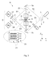
- Figure 3 illustrates a longitudinal cross-sectional view of a particular embodiment of a microscope M according to the present invention.
- the illustrated microscope M comprises (inter alia) an illumination portion (to the right of axis O) and a detection portion (to the left of axis O).
- Said illumination portion essentially corresponds to the set-up shown in Figure 1 (but could just as easily be based on the set-up shown in Figure 2 ); therefore, so as to avoid unnecessary repetition, the following discussion will concentrate on said detection portion.
- illumination of (a collection of fluorophores in) specimen S - using suitably chosen activation and excitation wavelengths - will cause (certain of) those fluorophores to emit fluorescence light, which is (partially) collected by projection systems P1, P2.
- OCE Optical Combining Element
- a detector arrangement D - which here comprises two detectors Da, Db - is used to examine this interference pattern, by simultaneously looking at it along two different (mutually phase-shifted) "channels": see Figure 4A , for example.
- Also symbolically shown in Figure 3 are generic optics 27, 29, which, for example, serve a focusing/collimation function.
- the beam-splitting surface C' of OCE C is located in the same plane as specimen S; in that case, the phases of fluorescence emission of the beams B1 and B2 are "balanced" relative to the beam splitter position.
- Figure 6 illustrates a graph in which curves such as those in Figures 4B and 5B have been combined / superimposed. Because the component curves have different frequencies (as a function of Z), they will inevitably cross each other at certain points - such as in depicted zones r5, r6, for example. In such zones, measurement sensitivity will tend to be relatively low.
Landscapes
- Physics & Mathematics (AREA)
- General Physics & Mathematics (AREA)
- Chemical & Material Sciences (AREA)
- Analytical Chemistry (AREA)
- Optics & Photonics (AREA)
- Health & Medical Sciences (AREA)
- Biochemistry (AREA)
- Life Sciences & Earth Sciences (AREA)
- General Health & Medical Sciences (AREA)
- Immunology (AREA)
- Pathology (AREA)
- Engineering & Computer Science (AREA)
- Multimedia (AREA)
- Nuclear Medicine, Radiotherapy & Molecular Imaging (AREA)
- Investigating, Analyzing Materials By Fluorescence Or Luminescence (AREA)
- Microscoopes, Condenser (AREA)
Abstract
- A specimen holder, for holding a specimen at an analysis location;
- An illuminator, for illuminating the specimen with input radiation, so as to cause it to emit fluorescence light;
- A pair of projection systems, arranged at opposite sides of said analysis location, to collect at least a portion of said fluorescence light and direct a corresponding pair of light beams into a respective pair of inputs of an optical combining element, where they optically interfere;
- A detector arrangement, for examining output light from said combining element, wherein:
- The illuminator is configured to produce a standing wave of input radiation at the analysis location
- The detector arrangement comprises exactly two interferometric detection branches.
Description
- The invention relates to a wide-field interferometric microscope comprising:
- A specimen holder, for holding a specimen at an analysis location;
- An illuminator, for illuminating the specimen with input radiation, so as to cause it to emit fluorescence light;
- A pair of projection systems, arranged at opposite sides of said analysis location, to collect at least a portion of said fluorescence light and direct a corresponding pair of light beams into a respective pair of inputs of an optical combining element, where they optically interfere;
- A detector arrangement, for examining light output from said combining element.
- The invention also relates to a method of using such a microscope.
- A microscope as set forth above is, for example, known from the field of interferometric Photo-Activated Localization Microscopy (iPALM), which, for example, is elucidated in more detail in the following references:
- http://www.pnas.org/content/106/9/3125.full
- http://www.mechanobio.info/topics/methods/super-resolution-microscopy-intro
- In PALM, lateral super-resolution is achieved by sequentially exciting spatially sparse subsets of objects (photoactivatable fluorophores) in a specimen, causing temporal separation of fluorescence emission from these different subsets. The resolvability of objects within each of these sparse subsets is greater than if the whole specimen were to be imaged in one go. In essence, the resolution-limiting diffraction effects that one would expect if one were to attempt to simultaneously image a dense set of objects are circumvented by instead regarding the set as a cumulative collective of sparse subsets, which are sequentially imaged. The photoactivatable fluorophores are caused to fluoresce in a two-step process, whereby:
- ▪ In a preliminary step, a so-called "activating wavelength" (or "activation wavelength") is used to promote the fluorophore from a non-emissive to an emissive state;
- ▪ In a subsequent step, a so-called "exciting wavelength" (or "excitation wavelength") is used to cause radiative "relaxation" of the activated fluorophore (fluorescence excitation).
- In iPALM, the lateral (XY) super-resolution achieved in PALM is taken a step further, by introducing a mechanism that will also allow fine axial/depth (Z) resolution. This is achieved by imaging the (fluorophores in the) specimen through a pair of oppositely disposed projection systems (objective lenses, optical columns), whose output beams are fed into an optical combining element (specifically, a three-phase beam splitter), where they optically interfere. The resulting interference fringe pattern will be (very) sensitive to the axial (depth) position of the object (fluorophore) being imaged, since this will influence the relative path lengths of the interfering beams. By using a detector arrangement comprising multiple detectors (e.g. CCDs) to selectively look at phase-separated outputs from the combining element, one can effectively (mathematically) "translate" a given fringe pattern into a deduced axial object position; in iPALM, three distinct outputs from the combining element (mutually phase-shifted by 120°) are observed using three different detectors (cameras), whereby the relative intensities of the outputs observed by these cameras will change in a predictable manner as a function of axial fluorophore position.
- Although iPALM is a useful technique, it does suffer from drawbacks. More specifically, it relies on a relatively complicated optical/detection architecture. In particular:
- The employed three-phase beam splitter is an expensive and fragile component that is difficult to manufacture. Its performance is sensitive to temperature fluctuations and mechanical vibrations, and it has a relatively long settling time after being disturbed. Moreover, it is difficult to optically align/adjust.
- The employed three-phase beam splitter is also difficult to mechanically scale up in size, e.g. to match cameras with a larger field of view (without vignetting). Limiting factors in this regard include tolerances on the planar optics of the beam splitter, and coherence characteristics of the fluorescence light.
- The detection set-up requires the use of three detectors/cameras, which increases bulk / decreases available space, and increases expense.
- For good order, it is noted that, in addition to PALM/iPALM, there are also various other types of fluorescence microscopy in use, such as STORM and dSTORM, for example. More information in this regard can, for example, be gleaned from the following reference: https://en.wikipedia.org/wiki/Super-resolution microscopy
- One should note the distinction between a wide-field microscope - which can be regarded as employing a planar imaging wave - and, for example, a point scanning microscope (German: "Rastermikroscop"), which uses an imaging beam that is focused to a point, and is thus (necessarily) scanned over an object to be imaged. The present invention relates to the former (wide field). Examples of the latter (point scanning) are, for example, set forth in
EP 0 491 289 A1 - It is an object of the invention to address these issues. In particular, it is an object of the invention to provide an alternative depth-resolved localization microscopy technique that utilizes a radically different illumination/detection configuration. More specifically, it is an object of the invention that does not require use of a three-phase beam splitter.
- These and other objects are achieved in a microscope as specified in the opening paragraph above, characterized in that:
- The illuminator comprises an optical cavity that is configured to produce a standing wave of input radiation at the analysis location;
- The detector arrangement comprises exactly two interferometric detection branches.
- The following aspects of the invention merit explicit mention:
- (i) The standing wave alluded to here may be produced using the "activating" input light or the "exciting" input light, and will extend in a direction along the (local) optical axis at the analysis location.
- (ii) This standing wave produces a (sinusoidal) modulation of the input radiation that illuminates the specimen, and it has a phase that can be tuned, e.g. by adjusting the "length" of the optical cavity in which it is generated.
- (iii) Aspect (ii) can be exploited to provide an alternative for (at least) one of the three 120°-degree-phase-shifted beams used in the conventional iPALM detection set-up; since three detection beams are thus rendered unnecessary, one no longer needs to use a troublesome three-phase beam splitter and associated trio of cameras - instead, one can suffice with a regular two-way beam splitter, which is much cheaper, less fragile, and more easily manufactured (and scaled to larger sizes).
- (iv) The spatially modulated intensity distribution in the standing wave admits innovative ways of activating/exciting the fluorophores in the specimen, which can serve as a basis for new effects and advantages.
- Detector arrangements that use only one detector (branch/channel), e.g. as set forth in
US 2005/0006597 A1 andEP 0 491 289 A1 - Detector arrangements that use three detectors (branches/channels), e.g. as described above/below, and as set forth in
US 2006/0291043 A1 (in which it should be noted that no interferometric imaging is done: the three employed cameras are only used to detect different wavelengths). - There are various ways in which to realize/configure an illuminator of the type used by the invention. In a particular embodiment, the illuminator comprises:
- A beam splitter, to produce a pair of coherent beams from a single source (e.g. a laser);
- A pair of reflectors, to direct each of said pair of coherent beams through a respective one of the employed pair of projection systems,
- In an alternative embodiment to that set forth in the previous paragraph, the illuminator comprises:
- A laser, located at a first side of said analysis location, to direct an input beam along a common optical axis of said pair of projection systems and through said specimen in a first direction;
- A movable mirror, located at a second, opposite side of said analysis location and arranged normal to said common optical axis, to reflect said input beam back upon itself and through said specimen in a second, opposite direction.
- In a refinement of the set-up described in the previous paragraph, the illuminator can optionally comprise an optical diode or 50:50 plate beam splitter (for example) provided between said laser and said movable mirror. Such an embodiment serves to mitigate feedback effects in the lasing cavity.
- In the single-insertion embodiments just discussed, adjusting the axial position of the movable mirror (along the local optical axis) allows the phase of the standing wave (at the analysis location) to be modified. A similar effect can be achieved in the preceding "dual-insertion" embodiment by, for example:
- Incorporating an adjustable optical retarder element in the path of at least one of the two input beams (as shown in
Figures 1 and3 ); or/and - Moving (at least) one of the pair of reflectors (and, if necessary, co-moving the beam splitter), so as to adjust the axial separation of the reflectors.
- As already stated above, the standing wave utilized in the present invention may be generated using light from the activating light source (e.g. a laser with a wavelength of 405nm) or the exciting light source (e.g. a laser with a wavelength of 488nm, 561 nm, 639nm or 750nm); such aspects relate to the illumination architecture of the inventive microscope. In addition to illumination optics, the invention is also concerned with the detection optics of the microscope. In that regard, a particular embodiment of the invention is characterized in that the employed optical combining element (OCE) comprises a two-way beam-splitter (as already alluded to above). This can be used in conjunction with a detector arrangement comprising two cameras, which look at two mutually phase-shifted outputs from the (OCE): see
Figure 3 , for example. In what follows, it will be explained why/how the standing wave generated in the present invention allows a less complicated OCE and a less complicated detector arrangement than in iPALM (and similar techniques). - Referring now to
Figure 4A , this shows a graph of measured intensity (lin) versus axial position (Z) of (a fluorescing portion of) a specimen S as measured by detectors (cameras) Da (which registers intensity lin1) and Db (which registers intensity lin2) in a set-up such as that shown inFigure 3 (whereby the suffix "in" denotes "interference"). It is noted that lin1 and lin2 demonstrate a sinusoidal dependence on Z. The intensity lin on a given detector is determined by the sum/difference of the electromagnetic fields EB1 and EB2 associated with (travelling along) beams B1 and B2, respectively, whereby:
Figure 4B shows the so-called Normalized Differential Intensity (Qin) as a function of Z, whereby:
Figure 4B is also sometimes referred to as a "calibration curve" for the employed detector arrangement. It is noted that the slope of this calibration curve reduces significantly in zones such as r1 and r2, which respectively correspond to a local maximum and local minimum of the curve; in these "dud" zones r1, r2, there is therefore a correspondingly lowered detection sensitivity. As a result, if, at/near a given Z-value, the value of Qin is extremal or near to extremal (corresponding to zones such as r1, r2), then it will be difficult to accurately determine the Z-value in question, which is an undesirable situation. This issue can be dealt with in different ways: - (a) In conventional iPALM, the underlying problem is addressed by using three detection channels, which are mutually phase-shifted by 120°/240°; as a result, if the Normalized Differential Intensity (NDI) for a given Z-value and a given pair of channels lands in a dud zone, then one can instead use the NDI based on a different pair of channels, which (for the same Z-value) will (necessarily) lie outside a dud zone.
- (b) In contrast, the present invention does not need to rely on such a third channel, and instead solves the problem of dud zones in a completely different manner. In this regard, reference is made to
Figures 5A and 5B , which relate to the innovative standing wave set-up of the current invention (whereby the suffix "sw" denotes "standing wave"). In this particular instance, the standing wave in question is generated using an illumination wavelength of 488nm, but that is not limiting upon the current discussion.Figure 5A shows the intensity (Isw1) of a first standing wave as a function of axial position (Z), and also shows the intensity (Isw2) of a second, axially displaced standing wave as a function of axial position (Z), whereby there is a phase difference Δϕ = π between said first and second standing waves.Figure 5B shows the calibration curve corresponding toFigure 5A [Qsw versus Z, with Qsw = (Isw1-Isw2)/(Isw1+Isw2)]. Note the "flank" zones r3, r4 in which the slope of the curve is greatest, corresponding to greatest sensitivity. By adding a phase shift δ to Isw1/Isw2 (e.g. by suitably moving retarding element R inFigure 1 or3 ), one can cause the calibration curve ofFigure 5B - and, therefore, the position of flank zones r3, r4 - to shift along Z. In particular, one can Z-shift the calibration curve ofFigure 5B so that one of its flank zones (r3, r4; maximum sensitivity) corresponds to a dud zone (r1, r2; minimum sensitivity) of the calibration curve ofFigure 4B . In essence, one effectively takes four measurements, namely:- lin1, lin2 at a first standing wave phase value Δϕ;
- lin1', lin2' at a second standing wave phase value δ + Δϕ,
- As already set forth above, the present invention uses an innovative illumination set-up, which correspondingly allows an innovative detection set-up to be employed. In a further aspect of the present invention:
- Said standing wave is produced using said first type of radiation;
- Said selected fluorophores are activated in a depth region of the specimen proximal to a local maximum of said standing wave.
- In a particular aspect of the invention, wavefront modifying means are used to produce astigmatism in light entering the optical combining element. To this end, one could, for example, employ a cylindrical lens or mirror, or introduce a (cylindrical) stress into a planar mirror (such as a folding mirror), in at least one / preferably both of the dual detection branches of the microscope. Introducing astigmatism (more generally: wavefront modification that varies in polarity as a function of axial position) in this manner causes an associated Point Spread Function (PSF) to demonstrate ellipticity "oscillations" as a function of Z - changing from elongate along Y, to circular, to elongate along X, etc. Observing the form of this PSF at a given axial position can then be used to help determine a Z-value for that position - more specifically, it acts as a check on the "sign" of a Z-coordinate of known amplitude.
- For some further information on fluorophores and their use in fluorescence microscopy, reference is made to the following sources: https://en.wikipedia.org/wiki/Fluorophore
- J. Lippincott-Schwartz & G. Patterson, Photoactivatable fluorescent proteins for diffraction-limited and super-resolution imaging, Trends in Cell Biology 19 (11), pp. 555-565, Elsevier Ltd., 2009.
- The invention will now be elucidated in more detail on the basis of exemplary embodiments and the accompanying schematic drawings, in which:
-
Figure 1 illustrates a longitudinal cross-sectional view of part of an embodiment of a microscope according to the present invention. -
Figure 2 illustrates a longitudinal cross-sectional view of part of another embodiment of a microscope according to the present invention. -
Figure 3 illustrates a longitudinal cross-sectional view of a particular embodiment of a microscope according to the present invention. -
Figures 4A and 4B respectively show graphs of intensity (lin) and Normalized Differential Intensity (Qin) as a function of axial position (Z) for two interfering light beams in an optical combining element. -
Figures 5A and 5B respectively show graphs of intensity (Isw) and Normalized Differential Intensity (Qsw) as a function of axial position (Z) for two phase-shifted standing waves, produced in an illuminator according to the current invention. -
Figure 6 illustrates a graph in which curves such as those inFigures 4B and5B have been combined / superimposed. - In the Figures, where pertinent, corresponding parts may be indicated using corresponding reference symbols.
-
Figure 1 illustrates a longitudinal cross-sectional view of part of an embodiment of a microscope (M) according to the present invention. More particularly, it illustrates an embodiment of an illuminator IL for such a microscope. In the Figure, a laser L produces abeam 1 of "input radiation", which, in the context of the present invention, may be an activation beam or an excitation beam for respectively activating/exciting a fluorophore in fluorescence microscopy. Thisbeam 1 serves to illuminate (activate and/or excite) (a collection of fluorophores in) specimen S that is held on a specimen holder H at an analysis location A, (ultimately) causing (part of) specimen S to emit fluorescence light. The analysis location A is straddled by a pair of oppositely-located projection systems P1, P2, which will serve to collect this fluorescence light and direct it onto a detector arrangement D (to be discussed in the context ofFigure 3 ); for now, the present discussion will concentrate on the structure/functioning of illuminator IL. - The
beam 1 encounters a two-way beam splitter 3, which divides thebeam 1 into a pair of coherentlight beams item 3. Thebeams beams beam 5a traverses analysis area A along O through P1, whereas divertedbeam 5b traverses analysis area A along O through P2, and these two diverted beams produce a (longitudinal/axial) standing wave at location A (and elsewhere in the path / optical cavity A, 7a, 3, 7b, A). As schematically illustrated inFigure 3 , such astanding wave 31 will have alternating maxima and minima disposed along axis Z (of illustrated Cartesian coordinate system X, Y, Z), which extends parallel to O. - Also symbolically/generically shown are
optics 9, 11, which, for example, serve to focus/collimate thebeams wave 31 to be adjusted. As an alternative or supplement to this, one could also shift (at least) one of thereflectors e.g. shift reflector 7a as shown by the arrow symbol beside it. -
Figure 2 illustrates a longitudinal cross-sectional view of part of another embodiment of a microscope according to the present invention; more particularly, it illustrates an embodiment of an illuminator IL for such a microscope. Certain parts ofFigure 2 that are also present inFigure 1 will not necessarily be discussed here; instead, the following discussion will concentrate on the differences between the two Figures. - In
Figure 2 , a canted mirror 17 (optional) is located at a first side ("P2-side" or "upstream") of analysis location A; this is used to direct an input beam from a laser L along common optical axis O of projection systems P2, P1 and through specimen S in a first direction (+Z). Use is also made of a movable mirror (reflector) 13, which is arranged to be substantially normal to optical axis O, can be displaced along O in a controlled manner, and is situated at a second, opposite side ("P1-side" or "downstream") of analysis location A; this serves to reflect said input beam back upon itself and through specimen S in a second, opposite direction (-Z). The outgoing (+Z) and returning (-Z) beam from L interact to produce a standing wave (inter alia at A). Displacement ofmirror 13 along axis O allows the phase of this standing wave to be adjusted. Also symbolically/generically shown areoptics - Optionally present in
Figure 2 is adevice 15 such as an optical diode 15 (e.g. a Faraday Isolator) or a 50:50 plate beam splitter. -
Figure 3 illustrates a longitudinal cross-sectional view of a particular embodiment of a microscope M according to the present invention. The illustrated microscope M comprises (inter alia) an illumination portion (to the right of axis O) and a detection portion (to the left of axis O). Said illumination portion essentially corresponds to the set-up shown inFigure 1 (but could just as easily be based on the set-up shown inFigure 2 ); therefore, so as to avoid unnecessary repetition, the following discussion will concentrate on said detection portion. - As already set forth above, illumination of (a collection of fluorophores in) specimen S - using suitably chosen activation and excitation wavelengths - will cause (certain of) those fluorophores to emit fluorescence light, which is (partially) collected by projection systems P1, P2. Using canted dichroic mirrors (reflectors) 23, 25 (positioned on axis O), light collected by P1 and P2 is respectively directed as beams B1, B2 into (a respective pair of input faces of) Optical Combining Element (OCE) C - which, in the current invention, can be a (relatively simple) two-phase beam splitter (combiner) rather than a (more complicated) three-phase beam splitter (combiner); within OCE C, the beams B1 and B2 optically interfere and produce an interference pattern (not depicted). A detector arrangement D - which here comprises two detectors Da, Db - is used to examine this interference pattern, by simultaneously looking at it along two different (mutually phase-shifted) "channels": see
Figure 4A , for example. Also symbolically shown inFigure 3 aregeneric optics - With reference to the elucidation already given above regarding
Figures 4A, 4B ,5A and 5B , a supplemental description will now be given as to how an inventive microscope such as that depicted inFigure 3 can be used. More particularly, the following discussion will concentrate on certain aspects of detection signal analysis/processing/interpretation. -
Figure 6 illustrates a graph in which curves such as those inFigures 4B and5B have been combined / superimposed. Because the component curves have different frequencies (as a function of Z), they will inevitably cross each other at certain points - such as in depicted zones r5, r6, for example. In such zones, measurement sensitivity will tend to be relatively low. - This problem can be addressed using a technique that is also exploited in iPALM. If the wavefront of the fluorescence light reaching the OCE C is deliberately deformed so as to introduce astigmatism - e.g. by deliberately mechanically stressing one / preferably both of the folding mirrors 23, 25 in
Figure 3 - then the associated Point Spread Function (PSF) 33 will demonstrate ellipticity "oscillations" as a function of Z - changing from elongate along Y, to circular, to elongate along X, etc. Observing the form of thePSF 33 at a given position can then be used to deduce a Z-value for that position. This is schematically depicted inFigure 6 , by illustrating exemplary PSF forms as a function of Z along the abscissa axis. - The basic mathematical analysis of the interference pattern in a microscope according to the current invention is similar to that pertaining to iPALM. For more information in this regard, reference is (for example) made to the mathematical discussion in United States Patent
US 7,924,432 , which is incorporated herein by reference.
This can be understood as follows:
Note that the invention is distinguished from:
Claims (10)
- A wide-field interferometric microscope comprising:- A specimen holder, for holding a specimen at an analysis location;- An illuminator, for illuminating the specimen with input radiation, so as to cause it to emit fluorescence light;- A pair of projection systems, arranged at opposite sides of said analysis location, to collect at least a portion of said fluorescence light and direct a corresponding pair of light beams into a respective pair of inputs of an optical combining element, where they optically interfere;- A detector arrangement, for examining output light from said combining element,characterized in that:- The illuminator comprises an optical cavity that is configured to produce a standing wave of input radiation at the analysis location;- The detector arrangement comprises exactly two interferometric detection branches.
- A microscope according to claim 1, wherein said illuminator comprises:- A beam splitter, to produce a pair of coherent beams from a single source;- A pair of reflectors, to direct each of said pair of coherent beams through a respective one of said pair of projection systems,whereby said optical cavity comprises said beam splitter and said pair of reflectors.
- A microscope according to claim 2, wherein said illuminator comprises an adjustable optical retarding element arranged in a path of at least one of said coherent beams.
- A microscope according to claim 1, wherein said illuminator comprises:- A laser, located at a first side of said analysis location, to direct an input beam along a common optical axis of said pair of projection systems and through said specimen in a first direction;- A movable mirror, located at a second, opposite side of said analysis location and arranged normal to said common optical axis, to reflect said input beam back upon itself and through said specimen in a second, opposite direction.
- A microscope according to any of claims 1-4, wherein said optical combining element comprises a two-way beam-splitter.
- A microscope according to any of claims 1-5, wherein said input radiation comprises:- A first type of radiation, for activating selected fluorophores in the specimen;- A second type of radiation, for exciting a set of activated fluorophores, with the resultant emission of fluorescence light,and wherein said standing wave is produced using either said first type or said second type of radiation.
- A microscope according to claim 6, wherein:- Said standing wave is produced using said first type of radiation;- Said selected fluorophores are activated in a depth region of the specimen proximal to a local maximum of said standing wave.
- A microscope according to any of claims 1-7, comprising wavefront modifying means for producing astigmatism in light entering the optical combining element.
- A method of using a wide-field interferometric microscope comprising:- A specimen holder, for holding a specimen at an analysis location;- An illuminator, for illuminating a region of the specimen with input radiation, so as to cause at least one fluorophore in said region to emit fluorescence light;- A pair of projection systems, arranged at opposite sides of said analysis location, to collect at least a portion of said fluorescence light and direct a corresponding pair of light beams into a respective pair of inputs of an optical combining element, where they optically interfere to produce an interference pattern;- A detector arrangement, for examining output light from said combining element,characterized by the following steps:(I) Using the illuminator to produce a standing wave of input radiation at the analysis location;(II) Using the detector arrangement to record an intensity distribution of said interference pattern along exactly two different channels;(III) Altering a phase of said standing wave, and repeating step (II) for this phase-altered wave;(IV) Using the intensity distributions recorded in steps (II) and (III) to derive an axial position of said fluorophore relative to a common optical axis of said pair of projection systems.
- A method according to claim 9, wherein wavefront modifying means are used to produce astigmatism in light entering the optical combining element.
Applications Claiming Priority (1)
| Application Number | Priority Date | Filing Date | Title |
|---|---|---|---|
| EP15190749.0A EP3159728A1 (en) | 2015-10-21 | 2015-10-21 | Standing wave interferometric microscope |
Publications (2)
| Publication Number | Publication Date |
|---|---|
| EP3159729A1 true EP3159729A1 (en) | 2017-04-26 |
| EP3159729B1 EP3159729B1 (en) | 2023-08-23 |
Family
ID=54337677
Family Applications (2)
| Application Number | Title | Priority Date | Filing Date |
|---|---|---|---|
| EP15190749.0A Withdrawn EP3159728A1 (en) | 2015-10-21 | 2015-10-21 | Standing wave interferometric microscope |
| EP16185525.9A Active EP3159729B1 (en) | 2015-10-21 | 2016-08-24 | Standing wave interferometric microscope |
Family Applications Before (1)
| Application Number | Title | Priority Date | Filing Date |
|---|---|---|---|
| EP15190749.0A Withdrawn EP3159728A1 (en) | 2015-10-21 | 2015-10-21 | Standing wave interferometric microscope |
Country Status (4)
| Country | Link |
|---|---|
| US (2) | US9885660B2 (en) |
| EP (2) | EP3159728A1 (en) |
| JP (1) | JP2017078855A (en) |
| CN (1) | CN107014786A (en) |
Families Citing this family (4)
| Publication number | Priority date | Publication date | Assignee | Title |
|---|---|---|---|---|
| EP3159728A1 (en) * | 2015-10-21 | 2017-04-26 | FEI Company | Standing wave interferometric microscope |
| CN108181282B (en) | 2018-01-03 | 2019-03-15 | 宁波纳美致生物科技有限公司 | A kind of triple channel fluorescence localization super-resolution biology microscope system and method |
| WO2020009902A1 (en) * | 2018-07-03 | 2020-01-09 | The United States Of America, As Represented By The Secretary, Department Of Health And Human Services | Systems and methods for improved axial resolution in microscopy using photoswitching and standing wave illumination techniques |
| CN121605338A (en) * | 2023-09-05 | 2026-03-03 | 索尼集团公司 | Optical system for observation of biological sample, measuring device, measuring method, and analysis program |
Citations (6)
| Publication number | Priority date | Publication date | Assignee | Title |
|---|---|---|---|---|
| EP0491289A1 (en) | 1990-12-18 | 1992-06-24 | Stefan Dr. Hell | Double-confocal scanning microscope |
| US20050006597A1 (en) | 2003-07-11 | 2005-01-13 | Carl Zeiss Jena Gmbh | Arrangement for the optical detection of light radiation which is excited and/or backscattered in a specimen with a double-objective arrangement |
| US20060291043A1 (en) | 2001-01-05 | 2006-12-28 | Leica Microsystems Heidelberg Gmbh | Interference microscope, and method for operating an interference microscope |
| US20080007248A1 (en) * | 2003-08-22 | 2008-01-10 | Centre National De La Recherche Scientifque-Cnrs | Non-invasive electric-filed-detection device and method |
| US7924432B2 (en) | 2006-12-21 | 2011-04-12 | Howard Hughes Medical Institute | Three-dimensional interferometric microscopy |
| US20140293015A1 (en) * | 2006-12-21 | 2014-10-02 | Howard Hughes Medical Institute | Systems and methods for 3-dimensional interferometric microscopy |
Family Cites Families (24)
| Publication number | Priority date | Publication date | Assignee | Title |
|---|---|---|---|---|
| US5671085A (en) * | 1995-02-03 | 1997-09-23 | The Regents Of The University Of California | Method and apparatus for three-dimensional microscopy with enhanced depth resolution |
| JPH09229861A (en) * | 1996-02-21 | 1997-09-05 | Bunshi Bio Photonics Kenkyusho:Kk | Fluorescence microscope |
| DE10250247B4 (en) * | 2002-10-28 | 2006-06-01 | Leica Microsystems Cms Gmbh | Sample carrier for microscopy and method for preparing a sample carrier |
| NL1027462C2 (en) | 2004-11-09 | 2006-05-10 | Koninkl Philips Electronics Nv | Method for locating fluorescent markers. |
| US7599069B2 (en) * | 2005-05-06 | 2009-10-06 | The University Of Chicago | Vector beam generator using a passively phase stable optical interferometer |
| JP4760564B2 (en) * | 2006-06-20 | 2011-08-31 | 日本電気株式会社 | Pattern shape defect detection method and detection apparatus |
| US8155409B2 (en) * | 2008-04-17 | 2012-04-10 | Ruprecht-Karls-Universitat | Wave field microscope with sub-wavelength resolution and methods for processing microscopic images to detect objects with sub-wavelength dimensions |
| US9213176B2 (en) * | 2008-12-02 | 2015-12-15 | The Regents Of The University Of California | Imaging arrangement and microscope |
| EP2629133A4 (en) * | 2010-10-14 | 2017-12-13 | Nikon Corporation | Structured illumination device, structured illumination microscope device, and surface shape measurement device |
| WO2012102887A2 (en) * | 2011-01-24 | 2012-08-02 | The Board Of Trustees Of The University Of Illinois | Computational adaptive optics for interferometric synthetic aperture microscopy and other interferometric imaging |
| US8319181B2 (en) | 2011-01-30 | 2012-11-27 | Fei Company | System and method for localization of large numbers of fluorescent markers in biological samples |
| JP5609729B2 (en) * | 2011-03-18 | 2014-10-22 | 横河電機株式会社 | Microscope device, observation method and sample mounting mechanism |
| DE102011017046A1 (en) | 2011-04-14 | 2012-10-18 | Till Photonics Gmbh | Switchable microscope arrangement with multiple detectors |
| US8237835B1 (en) * | 2011-05-19 | 2012-08-07 | Aeon Imaging, LLC | Confocal imaging device using spatially modulated illumination with electronic rolling shutter detection |
| FR2978254B1 (en) * | 2011-07-21 | 2014-01-24 | Imagine Optic | METHOD AND OPTICAL DEVICE FOR LOCATING A SUPER-RESOLUTION PARTICLE |
| KR20140068264A (en) * | 2011-10-12 | 2014-06-05 | 벤타나 메디컬 시스템즈, 인코포레이티드 | Obtain multifocal interference image |
| US20140333750A1 (en) * | 2011-12-15 | 2014-11-13 | President And Fellows Of Harvard College | High resolution dual-objective microscopy |
| DE102012200344A1 (en) * | 2012-01-11 | 2013-07-11 | Carl Zeiss Microscopy Gmbh | Microscope system and method for 3-D high-resolution microscopy |
| JPWO2013146365A1 (en) * | 2012-03-29 | 2015-12-10 | パナソニックIpマネジメント株式会社 | Fluorescence detection device |
| DE102012214568A1 (en) * | 2012-08-16 | 2014-02-20 | Leica Microsystems Cms Gmbh | Optical arrangement and a microscope |
| US8872105B2 (en) | 2013-02-19 | 2014-10-28 | Fei Company | In situ reactivation of fluorescence marker |
| WO2014152739A2 (en) * | 2013-03-14 | 2014-09-25 | The Regents Of The University Of California | Interferometric focusing of guide-stars for direct wavefront sensing |
| US9615735B2 (en) * | 2014-01-31 | 2017-04-11 | University Of Rochester | Measurement of the lipid and aqueous layers of a tear film |
| EP3159728A1 (en) * | 2015-10-21 | 2017-04-26 | FEI Company | Standing wave interferometric microscope |
-
2015
- 2015-10-21 EP EP15190749.0A patent/EP3159728A1/en not_active Withdrawn
-
2016
- 2016-08-24 EP EP16185525.9A patent/EP3159729B1/en active Active
- 2016-08-24 US US15/246,512 patent/US9885660B2/en active Active
- 2016-09-29 CN CN201610863720.XA patent/CN107014786A/en active Pending
- 2016-10-18 JP JP2016204524A patent/JP2017078855A/en active Pending
-
2018
- 2018-01-26 US US15/880,945 patent/US10401291B2/en active Active
Patent Citations (6)
| Publication number | Priority date | Publication date | Assignee | Title |
|---|---|---|---|---|
| EP0491289A1 (en) | 1990-12-18 | 1992-06-24 | Stefan Dr. Hell | Double-confocal scanning microscope |
| US20060291043A1 (en) | 2001-01-05 | 2006-12-28 | Leica Microsystems Heidelberg Gmbh | Interference microscope, and method for operating an interference microscope |
| US20050006597A1 (en) | 2003-07-11 | 2005-01-13 | Carl Zeiss Jena Gmbh | Arrangement for the optical detection of light radiation which is excited and/or backscattered in a specimen with a double-objective arrangement |
| US20080007248A1 (en) * | 2003-08-22 | 2008-01-10 | Centre National De La Recherche Scientifque-Cnrs | Non-invasive electric-filed-detection device and method |
| US7924432B2 (en) | 2006-12-21 | 2011-04-12 | Howard Hughes Medical Institute | Three-dimensional interferometric microscopy |
| US20140293015A1 (en) * | 2006-12-21 | 2014-10-02 | Howard Hughes Medical Institute | Systems and methods for 3-dimensional interferometric microscopy |
Non-Patent Citations (3)
| Title |
|---|
| DANIEL AQUINO ET AL: "Two-color nanoscopy of three-dimensional volumes by 4Pi detection of stochastically switched fluorophores", HHS PUBLIC ACCESS AUTHOR MANUSCRIPT, vol. 8, no. 4, 1 April 2011 (2011-04-01), GB, pages 353 - 359, XP055260855, ISSN: 1548-7091, DOI: 10.1038/nmeth.1583 * |
| J. LIPPINCOTT-SCHWARTZ; G. PATTERSON: "Trends in Cell Biology", vol. 19, 2009, ELSEVIER LTD., article "Photoactivatable fluorescent proteins for diffraction-limited and super-resolution imaging", pages: 555 - 565 |
| S.W. HELL ET AL.: "Enhancing the axial resolution in far-field light microscopy: two-photon 4Pi confocal fluorescence microscopy", J. MODERN OPTICS, vol. 41, no. 4, 1994, pages 675 - 681 |
Also Published As
| Publication number | Publication date |
|---|---|
| US20180195962A1 (en) | 2018-07-12 |
| EP3159728A1 (en) | 2017-04-26 |
| US9885660B2 (en) | 2018-02-06 |
| JP2017078855A (en) | 2017-04-27 |
| EP3159729B1 (en) | 2023-08-23 |
| US10401291B2 (en) | 2019-09-03 |
| US20170115224A1 (en) | 2017-04-27 |
| CN107014786A (en) | 2017-08-04 |
Similar Documents
| Publication | Publication Date | Title |
|---|---|---|
| US9470883B2 (en) | High-resolution scanning microscopy | |
| US8908174B2 (en) | Apparatus, especially microscope, for the analysis of samples | |
| US6958470B2 (en) | Scanning microscope with a detector and light source for exciting an energy state in a specimen and module for a scanning microscope | |
| US9645375B2 (en) | Light microscope and microscopy method | |
| US20030132394A1 (en) | Method and arrangement for the deep resolved optical recording or a sample | |
| US20090059360A1 (en) | System and method for self-interference fluorescence microscopy, and computer-accessible medium associated therewith | |
| JP5469133B2 (en) | Microscope system | |
| JP2003227796A (en) | Methods and arrangements for specimen grasping by deep decomposition | |
| JP6595618B2 (en) | Method for determining spatially resolved height information of a sample using a wide field microscope and a wide field microscope | |
| JP2007233370A (en) | Method and microscope for high spatial resolution examination of sample | |
| EP3159729B1 (en) | Standing wave interferometric microscope | |
| US20090242801A1 (en) | Method of fluorescence-microscopically imaging a structure in a sample with high three-dimensional spatial resolution | |
| CN103674926A (en) | Optical device | |
| GB2537786A (en) | Microspectroscopy device | |
| US7463344B2 (en) | Arrangement for the optical detection of light radiation which is excited and/or backscattered in a specimen with a double-objective arrangement | |
| JP2013113650A (en) | Trench depth measuring apparatus and trench depth measuring method and confocal microscope | |
| JP5592108B2 (en) | Interference confocal microscope and light source imaging method | |
| JP6659548B2 (en) | Multicolor scanning microscope | |
| JP5577998B2 (en) | Nonlinear microscope and nonlinear observation method | |
| US20020030886A1 (en) | Microscope | |
| EP2278264A1 (en) | Probe microscope | |
| JP2734786B2 (en) | Optical echo microscope | |
| Carlsson et al. | Use of UV excitation in confocal laser scanning fluorescence microscopy | |
| JP2017102013A (en) | Scanning type microscope | |
| US20120314200A1 (en) | Coupled multi-wavelength confocal systems for distance measurements |
Legal Events
| Date | Code | Title | Description |
|---|---|---|---|
| PUAI | Public reference made under article 153(3) epc to a published international application that has entered the european phase |
Free format text: ORIGINAL CODE: 0009012 |
|
| STAA | Information on the status of an ep patent application or granted ep patent |
Free format text: STATUS: THE APPLICATION HAS BEEN PUBLISHED |
|
| AK | Designated contracting states |
Kind code of ref document: A1 Designated state(s): AL AT BE BG CH CY CZ DE DK EE ES FI FR GB GR HR HU IE IS IT LI LT LU LV MC MK MT NL NO PL PT RO RS SE SI SK SM TR |
|
| AX | Request for extension of the european patent |
Extension state: BA ME |
|
| STAA | Information on the status of an ep patent application or granted ep patent |
Free format text: STATUS: REQUEST FOR EXAMINATION WAS MADE |
|
| 17P | Request for examination filed |
Effective date: 20171023 |
|
| RBV | Designated contracting states (corrected) |
Designated state(s): AL AT BE BG CH CY CZ DE DK EE ES FI FR GB GR HR HU IE IS IT LI LT LU LV MC MK MT NL NO PL PT RO RS SE SI SK SM TR |
|
| STAA | Information on the status of an ep patent application or granted ep patent |
Free format text: STATUS: EXAMINATION IS IN PROGRESS |
|
| 17Q | First examination report despatched |
Effective date: 20200807 |
|
| GRAP | Despatch of communication of intention to grant a patent |
Free format text: ORIGINAL CODE: EPIDOSNIGR1 |
|
| STAA | Information on the status of an ep patent application or granted ep patent |
Free format text: STATUS: GRANT OF PATENT IS INTENDED |
|
| RIC1 | Information provided on ipc code assigned before grant |
Ipc: G02B 27/58 20060101ALN20230217BHEP Ipc: G02B 21/00 20060101ALN20230217BHEP Ipc: G02B 21/14 20060101ALI20230217BHEP Ipc: G02B 21/16 20060101AFI20230217BHEP |
|
| RIC1 | Information provided on ipc code assigned before grant |
Ipc: G02B 27/58 20060101ALN20230309BHEP Ipc: G02B 21/00 20060101ALN20230309BHEP Ipc: G02B 21/14 20060101ALI20230309BHEP Ipc: G02B 21/16 20060101AFI20230309BHEP |
|
| INTG | Intention to grant announced |
Effective date: 20230328 |
|
| GRAS | Grant fee paid |
Free format text: ORIGINAL CODE: EPIDOSNIGR3 |
|
| GRAA | (expected) grant |
Free format text: ORIGINAL CODE: 0009210 |
|
| STAA | Information on the status of an ep patent application or granted ep patent |
Free format text: STATUS: THE PATENT HAS BEEN GRANTED |
|
| AK | Designated contracting states |
Kind code of ref document: B1 Designated state(s): AL AT BE BG CH CY CZ DE DK EE ES FI FR GB GR HR HU IE IS IT LI LT LU LV MC MK MT NL NO PL PT RO RS SE SI SK SM TR |
|
| REG | Reference to a national code |
Ref country code: GB Ref legal event code: FG4D |
|
| REG | Reference to a national code |
Ref country code: CH Ref legal event code: EP |
|
| REG | Reference to a national code |
Ref country code: DE Ref legal event code: R096 Ref document number: 602016082093 Country of ref document: DE |
|
| REG | Reference to a national code |
Ref country code: IE Ref legal event code: FG4D |
|
| P01 | Opt-out of the competence of the unified patent court (upc) registered |
Effective date: 20231004 |
|
| REG | Reference to a national code |
Ref country code: LT Ref legal event code: MG9D |
|
| REG | Reference to a national code |
Ref country code: NL Ref legal event code: MP Effective date: 20230823 |
|
| REG | Reference to a national code |
Ref country code: AT Ref legal event code: MK05 Ref document number: 1603266 Country of ref document: AT Kind code of ref document: T Effective date: 20230823 |
|
| PG25 | Lapsed in a contracting state [announced via postgrant information from national office to epo] |
Ref country code: GR Free format text: LAPSE BECAUSE OF FAILURE TO SUBMIT A TRANSLATION OF THE DESCRIPTION OR TO PAY THE FEE WITHIN THE PRESCRIBED TIME-LIMIT Effective date: 20231124 |
|
| PG25 | Lapsed in a contracting state [announced via postgrant information from national office to epo] |
Ref country code: IS Free format text: LAPSE BECAUSE OF FAILURE TO SUBMIT A TRANSLATION OF THE DESCRIPTION OR TO PAY THE FEE WITHIN THE PRESCRIBED TIME-LIMIT Effective date: 20231223 |
|
| PG25 | Lapsed in a contracting state [announced via postgrant information from national office to epo] |
Ref country code: SE Free format text: LAPSE BECAUSE OF FAILURE TO SUBMIT A TRANSLATION OF THE DESCRIPTION OR TO PAY THE FEE WITHIN THE PRESCRIBED TIME-LIMIT Effective date: 20230823 Ref country code: RS Free format text: LAPSE BECAUSE OF FAILURE TO SUBMIT A TRANSLATION OF THE DESCRIPTION OR TO PAY THE FEE WITHIN THE PRESCRIBED TIME-LIMIT Effective date: 20230823 Ref country code: PT Free format text: LAPSE BECAUSE OF FAILURE TO SUBMIT A TRANSLATION OF THE DESCRIPTION OR TO PAY THE FEE WITHIN THE PRESCRIBED TIME-LIMIT Effective date: 20231226 Ref country code: NO Free format text: LAPSE BECAUSE OF FAILURE TO SUBMIT A TRANSLATION OF THE DESCRIPTION OR TO PAY THE FEE WITHIN THE PRESCRIBED TIME-LIMIT Effective date: 20231123 Ref country code: NL Free format text: LAPSE BECAUSE OF FAILURE TO SUBMIT A TRANSLATION OF THE DESCRIPTION OR TO PAY THE FEE WITHIN THE PRESCRIBED TIME-LIMIT Effective date: 20230823 Ref country code: LV Free format text: LAPSE BECAUSE OF FAILURE TO SUBMIT A TRANSLATION OF THE DESCRIPTION OR TO PAY THE FEE WITHIN THE PRESCRIBED TIME-LIMIT Effective date: 20230823 Ref country code: LT Free format text: LAPSE BECAUSE OF FAILURE TO SUBMIT A TRANSLATION OF THE DESCRIPTION OR TO PAY THE FEE WITHIN THE PRESCRIBED TIME-LIMIT Effective date: 20230823 Ref country code: IS Free format text: LAPSE BECAUSE OF FAILURE TO SUBMIT A TRANSLATION OF THE DESCRIPTION OR TO PAY THE FEE WITHIN THE PRESCRIBED TIME-LIMIT Effective date: 20231223 Ref country code: HR Free format text: LAPSE BECAUSE OF FAILURE TO SUBMIT A TRANSLATION OF THE DESCRIPTION OR TO PAY THE FEE WITHIN THE PRESCRIBED TIME-LIMIT Effective date: 20230823 Ref country code: GR Free format text: LAPSE BECAUSE OF FAILURE TO SUBMIT A TRANSLATION OF THE DESCRIPTION OR TO PAY THE FEE WITHIN THE PRESCRIBED TIME-LIMIT Effective date: 20231124 Ref country code: FI Free format text: LAPSE BECAUSE OF FAILURE TO SUBMIT A TRANSLATION OF THE DESCRIPTION OR TO PAY THE FEE WITHIN THE PRESCRIBED TIME-LIMIT Effective date: 20230823 Ref country code: AT Free format text: LAPSE BECAUSE OF FAILURE TO SUBMIT A TRANSLATION OF THE DESCRIPTION OR TO PAY THE FEE WITHIN THE PRESCRIBED TIME-LIMIT Effective date: 20230823 |
|
| PG25 | Lapsed in a contracting state [announced via postgrant information from national office to epo] |
Ref country code: PL Free format text: LAPSE BECAUSE OF FAILURE TO SUBMIT A TRANSLATION OF THE DESCRIPTION OR TO PAY THE FEE WITHIN THE PRESCRIBED TIME-LIMIT Effective date: 20230823 |
|
| REG | Reference to a national code |
Ref country code: CH Ref legal event code: PL |
|
| PG25 | Lapsed in a contracting state [announced via postgrant information from national office to epo] |
Ref country code: LU Free format text: LAPSE BECAUSE OF NON-PAYMENT OF DUE FEES Effective date: 20230824 |
|
| PG25 | Lapsed in a contracting state [announced via postgrant information from national office to epo] |
Ref country code: ES Free format text: LAPSE BECAUSE OF FAILURE TO SUBMIT A TRANSLATION OF THE DESCRIPTION OR TO PAY THE FEE WITHIN THE PRESCRIBED TIME-LIMIT Effective date: 20230823 |
|
| PG25 | Lapsed in a contracting state [announced via postgrant information from national office to epo] |
Ref country code: SM Free format text: LAPSE BECAUSE OF FAILURE TO SUBMIT A TRANSLATION OF THE DESCRIPTION OR TO PAY THE FEE WITHIN THE PRESCRIBED TIME-LIMIT Effective date: 20230823 Ref country code: RO Free format text: LAPSE BECAUSE OF FAILURE TO SUBMIT A TRANSLATION OF THE DESCRIPTION OR TO PAY THE FEE WITHIN THE PRESCRIBED TIME-LIMIT Effective date: 20230823 Ref country code: LU Free format text: LAPSE BECAUSE OF NON-PAYMENT OF DUE FEES Effective date: 20230824 Ref country code: ES Free format text: LAPSE BECAUSE OF FAILURE TO SUBMIT A TRANSLATION OF THE DESCRIPTION OR TO PAY THE FEE WITHIN THE PRESCRIBED TIME-LIMIT Effective date: 20230823 Ref country code: EE Free format text: LAPSE BECAUSE OF FAILURE TO SUBMIT A TRANSLATION OF THE DESCRIPTION OR TO PAY THE FEE WITHIN THE PRESCRIBED TIME-LIMIT Effective date: 20230823 Ref country code: DK Free format text: LAPSE BECAUSE OF FAILURE TO SUBMIT A TRANSLATION OF THE DESCRIPTION OR TO PAY THE FEE WITHIN THE PRESCRIBED TIME-LIMIT Effective date: 20230823 Ref country code: CZ Free format text: LAPSE BECAUSE OF FAILURE TO SUBMIT A TRANSLATION OF THE DESCRIPTION OR TO PAY THE FEE WITHIN THE PRESCRIBED TIME-LIMIT Effective date: 20230823 Ref country code: CH Free format text: LAPSE BECAUSE OF NON-PAYMENT OF DUE FEES Effective date: 20230831 Ref country code: SK Free format text: LAPSE BECAUSE OF FAILURE TO SUBMIT A TRANSLATION OF THE DESCRIPTION OR TO PAY THE FEE WITHIN THE PRESCRIBED TIME-LIMIT Effective date: 20230823 |
|
| REG | Reference to a national code |
Ref country code: BE Ref legal event code: MM Effective date: 20230831 |
|
| REG | Reference to a national code |
Ref country code: IE Ref legal event code: MM4A |
|
| REG | Reference to a national code |
Ref country code: DE Ref legal event code: R097 Ref document number: 602016082093 Country of ref document: DE |
|
| PG25 | Lapsed in a contracting state [announced via postgrant information from national office to epo] |
Ref country code: IT Free format text: LAPSE BECAUSE OF FAILURE TO SUBMIT A TRANSLATION OF THE DESCRIPTION OR TO PAY THE FEE WITHIN THE PRESCRIBED TIME-LIMIT Effective date: 20230823 Ref country code: MC Free format text: LAPSE BECAUSE OF FAILURE TO SUBMIT A TRANSLATION OF THE DESCRIPTION OR TO PAY THE FEE WITHIN THE PRESCRIBED TIME-LIMIT Effective date: 20230823 |
|
| PLBE | No opposition filed within time limit |
Free format text: ORIGINAL CODE: 0009261 |
|
| STAA | Information on the status of an ep patent application or granted ep patent |
Free format text: STATUS: NO OPPOSITION FILED WITHIN TIME LIMIT |
|
| PG25 | Lapsed in a contracting state [announced via postgrant information from national office to epo] |
Ref country code: IE Free format text: LAPSE BECAUSE OF NON-PAYMENT OF DUE FEES Effective date: 20230824 |
|
| 26N | No opposition filed |
Effective date: 20240524 |
|
| PG25 | Lapsed in a contracting state [announced via postgrant information from national office to epo] |
Ref country code: IE Free format text: LAPSE BECAUSE OF NON-PAYMENT OF DUE FEES Effective date: 20230824 Ref country code: FR Free format text: LAPSE BECAUSE OF NON-PAYMENT OF DUE FEES Effective date: 20231023 Ref country code: SI Free format text: LAPSE BECAUSE OF FAILURE TO SUBMIT A TRANSLATION OF THE DESCRIPTION OR TO PAY THE FEE WITHIN THE PRESCRIBED TIME-LIMIT Effective date: 20230823 |
|
| PG25 | Lapsed in a contracting state [announced via postgrant information from national office to epo] |
Ref country code: BE Free format text: LAPSE BECAUSE OF NON-PAYMENT OF DUE FEES Effective date: 20230831 |
|
| PG25 | Lapsed in a contracting state [announced via postgrant information from national office to epo] |
Ref country code: BG Free format text: LAPSE BECAUSE OF FAILURE TO SUBMIT A TRANSLATION OF THE DESCRIPTION OR TO PAY THE FEE WITHIN THE PRESCRIBED TIME-LIMIT Effective date: 20230823 |
|
| PG25 | Lapsed in a contracting state [announced via postgrant information from national office to epo] |
Ref country code: BG Free format text: LAPSE BECAUSE OF FAILURE TO SUBMIT A TRANSLATION OF THE DESCRIPTION OR TO PAY THE FEE WITHIN THE PRESCRIBED TIME-LIMIT Effective date: 20230823 |
|
| PG25 | Lapsed in a contracting state [announced via postgrant information from national office to epo] |
Ref country code: CY Free format text: LAPSE BECAUSE OF FAILURE TO SUBMIT A TRANSLATION OF THE DESCRIPTION OR TO PAY THE FEE WITHIN THE PRESCRIBED TIME-LIMIT; INVALID AB INITIO Effective date: 20160824 |
|
| PG25 | Lapsed in a contracting state [announced via postgrant information from national office to epo] |
Ref country code: HU Free format text: LAPSE BECAUSE OF FAILURE TO SUBMIT A TRANSLATION OF THE DESCRIPTION OR TO PAY THE FEE WITHIN THE PRESCRIBED TIME-LIMIT; INVALID AB INITIO Effective date: 20160824 |
|
| PGFP | Annual fee paid to national office [announced via postgrant information from national office to epo] |
Ref country code: DE Payment date: 20250714 Year of fee payment: 10 |
|
| PGFP | Annual fee paid to national office [announced via postgrant information from national office to epo] |
Ref country code: GB Payment date: 20250811 Year of fee payment: 10 |
|
| PG25 | Lapsed in a contracting state [announced via postgrant information from national office to epo] |
Ref country code: TR Free format text: LAPSE BECAUSE OF FAILURE TO SUBMIT A TRANSLATION OF THE DESCRIPTION OR TO PAY THE FEE WITHIN THE PRESCRIBED TIME-LIMIT Effective date: 20230823 |