EP3159687A1 - Device and method for testing impedance characteristic and expansion performance of sound absorption material - Google Patents
Device and method for testing impedance characteristic and expansion performance of sound absorption material Download PDFInfo
- Publication number
- EP3159687A1 EP3159687A1 EP15863389.1A EP15863389A EP3159687A1 EP 3159687 A1 EP3159687 A1 EP 3159687A1 EP 15863389 A EP15863389 A EP 15863389A EP 3159687 A1 EP3159687 A1 EP 3159687A1
- Authority
- EP
- European Patent Office
- Prior art keywords
- cavity
- sound
- absorption material
- sound absorption
- acoustic
- Prior art date
- Legal status (The legal status is an assumption and is not a legal conclusion. Google has not performed a legal analysis and makes no representation as to the accuracy of the status listed.)
- Granted
Links
Images
Classifications
-
- G—PHYSICS
- G01—MEASURING; TESTING
- G01H—MEASUREMENT OF MECHANICAL VIBRATIONS OR ULTRASONIC, SONIC OR INFRASONIC WAVES
- G01H15/00—Measuring mechanical or acoustic impedance
-
- G—PHYSICS
- G01—MEASURING; TESTING
- G01B—MEASURING LENGTH, THICKNESS OR SIMILAR LINEAR DIMENSIONS; MEASURING ANGLES; MEASURING AREAS; MEASURING IRREGULARITIES OF SURFACES OR CONTOURS
- G01B17/00—Measuring arrangements characterised by the use of infrasonic, sonic or ultrasonic vibrations
-
- G—PHYSICS
- G01—MEASURING; TESTING
- G01H—MEASUREMENT OF MECHANICAL VIBRATIONS OR ULTRASONIC, SONIC OR INFRASONIC WAVES
- G01H3/00—Measuring characteristics of vibrations by using a detector in a fluid
-
- G—PHYSICS
- G01—MEASURING; TESTING
- G01N—INVESTIGATING OR ANALYSING MATERIALS BY DETERMINING THEIR CHEMICAL OR PHYSICAL PROPERTIES
- G01N29/00—Investigating or analysing materials by the use of ultrasonic, sonic or infrasonic waves; Visualisation of the interior of objects by transmitting ultrasonic or sonic waves through the object
- G01N29/04—Analysing solids
- G01N29/09—Analysing solids by measuring mechanical or acoustic impedance
-
- G—PHYSICS
- G01—MEASURING; TESTING
- G01N—INVESTIGATING OR ANALYSING MATERIALS BY DETERMINING THEIR CHEMICAL OR PHYSICAL PROPERTIES
- G01N29/00—Investigating or analysing materials by the use of ultrasonic, sonic or infrasonic waves; Visualisation of the interior of objects by transmitting ultrasonic or sonic waves through the object
- G01N29/04—Analysing solids
- G01N29/11—Analysing solids by measuring attenuation of acoustic waves
-
- G—PHYSICS
- G10—MUSICAL INSTRUMENTS; ACOUSTICS
- G10K—SOUND-PRODUCING DEVICES; METHODS OR DEVICES FOR PROTECTING AGAINST, OR FOR DAMPING, NOISE OR OTHER ACOUSTIC WAVES IN GENERAL; ACOUSTICS NOT OTHERWISE PROVIDED FOR
- G10K11/00—Methods or devices for transmitting, conducting or directing sound in general; Methods or devices for protecting against, or for damping, noise or other acoustic waves in general
- G10K11/16—Methods or devices for protecting against, or for damping, noise or other acoustic waves in general
- G10K11/162—Selection of materials
-
- G—PHYSICS
- G01—MEASURING; TESTING
- G01N—INVESTIGATING OR ANALYSING MATERIALS BY DETERMINING THEIR CHEMICAL OR PHYSICAL PROPERTIES
- G01N2291/00—Indexing codes associated with group G01N29/00
- G01N2291/02—Indexing codes associated with the analysed material
- G01N2291/028—Material parameters
Definitions
- the present disclosure relates to the technical field of material performance detection, and particularly to a device and a method for testing impedance characteristic and expansion performance of a sound absorption material.
- a sound absorption material is a material having a strong performance of absorbing acoustic energy and reducing noise.
- the sound absorption material placed in the cavity absorbs partial acoustic energy, and this is equivalent to expanding a capacity of the cavity. Since the sound absorption material has such expansion characteristic, technician in the acoustic field place the sound absorption material in the cavities of some acoustic products to expand the capacity of the cavities of products without increasing external volume of the products, to improve the performance of acoustic products.
- the first technical problem to be solved by the present disclosure is to provide a device for testing impedance characteristic and expansion performance of a sound absorption material.
- the device can test the impedance characteristic and expansion performance of the sound absorption material before it is installed in the acoustic product, thereby providing accurate technical indices for selection of the sound absorption material, eliminating waste of manpower and material resources, shortening the development cycle of acoustic products, and reducing the production costs of the product.
- the second technical problem to be solved by the present disclosure is to provide a method for testing impedance characteristic and expansion performance of a sound absorption material.
- the impedance characteristic and expansion performance of the sound absorption material can be accurately tested.
- the present disclosure employs the following technical solutions:
- the first cavity and the second cavity each are a cavity with a regular shape.
- the sounding face of the sound excitation source flushes with a surface of an inner wall of the first cavity.
- the sound excitation source is a speaker.
- the sound pickup sensor is a microphone.
- the sound isolation material is one of metal, bakelite and acrylic.
- the present disclosure employs the following technical solutions:
- a sound pressure level needed by the test in step S1 is a sound pressure level of an actual working environment of the sound absorption material.
- the device and method for testing impedance characteristic and expansion performance of a sound absorption material according to the present disclosure solve the technical problem in the prior art about difficulty in selecting the sound absorption material.
- the device and method for testing impedance characteristic and expansion performance of the sound absorption material according to the present disclosure implement performance test of the sound absorption material, provide technical indices for selection of the sound absorption material, reduce the production costs of the acoustic product, and bring about larger economic benefits to the enterprises.
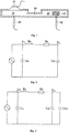
- the reference number 10 denotes first cavity
- 20 denotes second cavity
- 30 denotes slit channel
- 40 denotes sound absorption material
- 50 denotes sound excitation source
- 60 denotes first sound pickup sensor
- 62 denotes second sound pickup sensor
- P 11 denote sound pressure of the first cavity
- P 12 denote sound pressure of the second cavity
- M a denotes sound quality of the slit channel
- R a denotes acoustic impedance of the slit channel
- C a1 denotes equivalent acoustic capacitance of the first cavity
- C a2 denotes equivalent acoustic capacitance of the second cavity
- C dut denotes equivalent acoustic capacitance of the sound absorption material.
- a device for testing impedance characteristic and expansion performance of a sound absorption material comprises: a first cavity 10 and a second cavity 20 which are both sealed, wherein the first cavity 10 is communicated with the second cavity 20 through a slit channel 30.
- the device further comprises a sound excitation source 50 whose sounding face is located in the first cavity 10, and a first sound pickup sensor 60 whose sound pickup surface is located in the first cavity 10 and a second sound pickup sensor 62 whose sound pickup surface is located in the second cavity 20.
- both the first cavity 10 and second cavity 20 are a cavity of a regular shape such as cube, cuboid, cylinder or the like.
- Panel materials enclosing the first cavity 10 and second cavity 20 all are hard sound-isolating materials with strong reflectivity, for example, metallic, bakelite or acrylic plates with a thickness of over 2mm.
- a speaker is selected as the sound excitation source 50 to provide sound pressure upon testing the sound absorption performance.
- a sounding face of the sound excitation source 50 flushes with the surface of the inner wall of the first cavity so that the sound pressure at all positions in the cavity is in equilibrium.
- two high-sound pressure microphones are selected as the first sound pickup sensor 60 and the second sound pickup sensor 62 which are respectively used to detect the sound pressure in the first cavity 10 and the second cavity 20.
- Fig. 2 is an equivalent acoustic circuit diagram when the sound absorption material is not placed in the device.
- ⁇ is an angular speed
- C a2 is an equivalent acoustic capacitance of the second cavity 20.
- the sound absorption material 40 is placed in the second cavity 20, whereupon the acoustic circuit that is equivalent to the device after the sound absorption material is placed in the device is as shown in Fig. 3 .
- a uniform acoustic impedance Z L ( ⁇ ) after the sound absorption material 40 is placed in the second cavity 20 may be solved according to the acoustic circuit diagram,
- the method of using the above testing device to test impedance characteristic and expansion performance of a sound absorption material comprises the following steps:
- the device and method for testing impedance characteristic and expansion performance of a sound absorption material solve the technical difficulty of failure to test the impedance characteristic and expansion performance of the sound absorption material.
- Technicians may select a suitable sound absorption material for the acoustic product very quickly only according to the measured parameters of the sound absorption material such as equivalent acoustic capacitance and capacity expansion amount, thereby substantially shortening the development cycle of a new product, and meanwhile eliminating large waste of manpower and material resources, greatly reducing production costs of the acoustic product and bringing about larger economic benefits to the enterprises.
Landscapes
- Physics & Mathematics (AREA)
- General Physics & Mathematics (AREA)
- Acoustics & Sound (AREA)
- Health & Medical Sciences (AREA)
- Life Sciences & Earth Sciences (AREA)
- Chemical & Material Sciences (AREA)
- Analytical Chemistry (AREA)
- Biochemistry (AREA)
- General Health & Medical Sciences (AREA)
- Immunology (AREA)
- Pathology (AREA)
- Engineering & Computer Science (AREA)
- Multimedia (AREA)
- Measurement Of Mechanical Vibrations Or Ultrasonic Waves (AREA)
- Investigating Or Analyzing Materials By The Use Of Ultrasonic Waves (AREA)
- Soundproofing, Sound Blocking, And Sound Damping (AREA)
Abstract
Description
- The present disclosure relates to the technical field of material performance detection, and particularly to a device and a method for testing impedance characteristic and expansion performance of a sound absorption material.
- A sound absorption material is a material having a strong performance of absorbing acoustic energy and reducing noise. When the sound absorption material is placed in a cavity, and a cavity is filled with sound pressure, the sound absorption material placed in the cavity absorbs partial acoustic energy, and this is equivalent to expanding a capacity of the cavity. Since the sound absorption material has such expansion characteristic, technician in the acoustic field place the sound absorption material in the cavities of some acoustic products to expand the capacity of the cavities of products without increasing external volume of the products, to improve the performance of acoustic products.
- There are many kinds of materials capable of absorbing sound, but not every kind of sound absorption material has a very good expansion performance. To this end, technicians selects and uses a sound absorption material adapted for technical requirements of acoustic products from diverse sound absorption materials. However, currently there is not a device and a method for testing impedance characteristic and expansion performance of a sound absorption material. Technicians can only install each kind of sound absorption material into the acoustic product, then test to see whether the performance of the acoustic product changes or not, and thereby judge which sound absorption material is most adapted for the acoustic product. Such method of testing the sound absorption material is rather backward, causes large waste of manpower and material resources to enterprises, prolongs a development cycle of products, and thereby increases production costs of products.
- In view of the above drawbacks, the first technical problem to be solved by the present disclosure is to provide a device for testing impedance characteristic and expansion performance of a sound absorption material. The device can test the impedance characteristic and expansion performance of the sound absorption material before it is installed in the acoustic product, thereby providing accurate technical indices for selection of the sound absorption material, eliminating waste of manpower and material resources, shortening the development cycle of acoustic products, and reducing the production costs of the product.
- Based on a single general inventive concept, the second technical problem to be solved by the present disclosure is to provide a method for testing impedance characteristic and expansion performance of a sound absorption material. By the method, the impedance characteristic and expansion performance of the sound absorption material can be accurately tested.
- To solve the above first technical problem, the present disclosure employs the following technical solutions:
- A device for testing impedance characteristic and expansion performance of a sound absorption material comprises: a first cavity and a second cavity which are both sealed, the first cavity being communicated with the second cavity through a slit channel, wherein the second cavity is used for placing a sound absorption material therein; a sound excitation source whose sounding face is located in the first cavity and used to provide a testing sound pressure; two sound pickup sensors whose sound pickup surfaces are respectively arranged in the first cavity and the second cavity and which are respectively used to detect sound pressure in the first cavity and the second cavity; and a material for enclosing the first cavity and the second cavity is a hard sound insulation material.
- Preferably, the first cavity and the second cavity each are a cavity with a regular shape.
- Preferably, the sounding face of the sound excitation source flushes with a surface of an inner wall of the first cavity.
- Preferably, the sound excitation source is a speaker.
- Preferably, the sound pickup sensor is a microphone.
- Preferably, the sound isolation material is one of metal, bakelite and acrylic.
- To solve the above second technical problem, the present disclosure employs the following technical solutions:
- A method for testing impedance characteristic and expansion performance of a sound absorption material comprises the following steps:
- S1: adjusting a voltage of the sound excitation source to enable the sound pressure in the second cavity to satisfy a sound pressure level needed by the test;
- S2: Measuring a sound pressure P 11(ω) in the first cavity via the first sound pickup sensor, and measuring a sound pressure P 21(ω) in the second cavity via the second sound pickup sensor; solving an equivalent acoustic capacitance C a2 and an acoustic impedance Za2(ω) of the second cavity according to formula


- S3: obtaining formula

- S4: placing the sound absorption material to be tested in the second cavity, measuring a sound pressure P 12(ω) in the first cavity via the first sound pickup sensor, measuring a sound pressure P 22(ω) in the second cavity via the second sound pickup sensor, obtaining formula

- S5: obtaining formula


- Wherein, a sound pressure level needed by the test in step S1 is a sound pressure level of an actual working environment of the sound absorption material.
- The present disclosure achieves the following advantageous effects after employing the above technical solutions:
- In the present disclosure, the device for testing impedance characteristic and expansion performance of the sound absorption material device comprises: a first cavity and a second cavity which are both sealed, the first cavity being communicated with the second cavity through a slit channel; a sound excitation source whose sounding face is located in the first cavity; two sound pickup sensors respectively used to detect sound pressure in the first cavity and the second cavity; and a material for enclosing the first cavity and the second cavity is a sound insulation material. When the performance of the sound absorption material is tested, the sound pressure in the first cavity and second cavity and the impedance of the slit channel are detected first, then the sound absorption material to be tested is placed in the second cavity, then the sound pressure in the first cavity and second cavity at this time is detected, then the equivalent acoustic capacitance and capacity expansion amount of the sound absorption material are solved from a formula which is obtained from an acoustic circuit equivalently worked out by the device at this time. Whether the sound absorption material satisfies technical requirements of the acoustic product may be judged according to the obtained equivalent acoustic capacitance and capacity expansion amount of the sound absorption material. Hence, the sound absorption material adapted for the acoustic product may be selected in a way that the sound absorption material needn't be installed in the acoustic product. This eliminates waste of manpower and material resources caused by test of sound absorption material for each acoustic product, substantially shortens the time for selecting the sound absorption material, thereby shortening a development cycle of a new product, reducing production costs of products and bringing about larger economic benefits to enterprises.
- To conclude, the device and method for testing impedance characteristic and expansion performance of a sound absorption material according to the present disclosure solve the technical problem in the prior art about difficulty in selecting the sound absorption material. The device and method for testing impedance characteristic and expansion performance of the sound absorption material according to the present disclosure implement performance test of the sound absorption material, provide technical indices for selection of the sound absorption material, reduce the production costs of the acoustic product, and bring about larger economic benefits to the enterprises.
- The above depictions are only generalization of technical solutions of the present disclosure, which may be implemented according to content of the description to make technical means of the present disclosure clearer. Specific embodiments of the present disclosure are presented below to make the above and other objects, features and advantages of the present disclosure more apparent.
- The above features and technical advantages of the present disclosure be made clearer and more apparent by the following depictions of the present disclosure with reference to figures.
-
Fig. 1 is a structural schematic view of a device for testing impedance characteristic and expansion performance of a sound absorption material according to the present disclosure; -
Fig. 2 is an equivalent acoustic circuit diagram when the sound absorption material is not placed in the device for testing impedance characteristic and expansion performance of the sound absorption material according to the present disclosure; -
Fig. 3 is an equivalent acoustic circuit diagram after the sound absorption material is placed in the device for testing impedance characteristic and expansion performance of the sound absorption material according to the present disclosure; - In the figures, the
reference number 10 denotes first cavity, 20 denotes second cavity, 30 denotes slit channel, 40 denotes sound absorption material, 50 denotes sound excitation source, 60 denotes first sound pickup sensor, 62 denotes second sound pickup sensor, P 11, P 21 denote sound pressure of the first cavity, P 12, P 22 denote sound pressure of the second cavity, M a denotes sound quality of the slit channel, R a denotes acoustic impedance of the slit channel, C a1 denotes equivalent acoustic capacitance of the first cavity, C a2 denotes equivalent acoustic capacitance of the second cavity, Cdut denotes equivalent acoustic capacitance of the sound absorption material. - The present disclosure will be further illustrated with reference to figures and embodiments.
- As shown in
Fig. 1 , a device for testing impedance characteristic and expansion performance of a sound absorption material comprises: afirst cavity 10 and asecond cavity 20 which are both sealed, wherein thefirst cavity 10 is communicated with thesecond cavity 20 through aslit channel 30. The device further comprises asound excitation source 50 whose sounding face is located in thefirst cavity 10, and a firstsound pickup sensor 60 whose sound pickup surface is located in thefirst cavity 10 and a secondsound pickup sensor 62 whose sound pickup surface is located in thesecond cavity 20. - As shown in
Fig. 1 , both thefirst cavity 10 andsecond cavity 20 are a cavity of a regular shape such as cube, cuboid, cylinder or the like. Panel materials enclosing thefirst cavity 10 andsecond cavity 20 all are hard sound-isolating materials with strong reflectivity, for example, metallic, bakelite or acrylic plates with a thickness of over 2mm. - As shown in
Fig. 1 , in the present embodiment a speaker is selected as thesound excitation source 50 to provide sound pressure upon testing the sound absorption performance. A sounding face of thesound excitation source 50 flushes with the surface of the inner wall of the first cavity so that the sound pressure at all positions in the cavity is in equilibrium. - As shown in
Fig. 1 , in the present embodiment two high-sound pressure microphones are selected as the firstsound pickup sensor 60 and the secondsound pickup sensor 62 which are respectively used to detect the sound pressure in thefirst cavity 10 and thesecond cavity 20. - As jointly shown in
Fig. 1 and Fig. 2, Fig. 2 is an equivalent acoustic circuit diagram when the sound absorption material is not placed in the device. The acoustic impedance
second cavity 20 is solved from a capacitive reactance formula
- Wherein, ω is an angular speed,
C a2 is an equivalent acoustic capacitance of thesecond cavity 20. - The acoustic impedance Zref(ω) of the
slit channel 30 may be solved fromFig. 2 ,
- As jointly shown in
Fig. 1 and Fig. 3 , when the performance of the sound absorption material is tested, thesound absorption material 40 is placed in thesecond cavity 20, whereupon the acoustic circuit that is equivalent to the device after the sound absorption material is placed in the device is as shown inFig. 3 . A uniform acoustic impedance Z L(ω) after thesound absorption material 40 is placed in thesecond cavity 20 may be solved according to the acoustic circuit diagram, - The acoustic impedance of the
sound absorption material 40 is


- As shown in
Fig. 1, Fig. 2 and Fig. 3 , the method of using the above testing device to test impedance characteristic and expansion performance of a sound absorption material comprises the following steps: - S1: calibrating the sound pressure in the
second cavity 20, namely, detecting the sound pressure in thesecond cavity 20 via the secondsound pickup sensor 62 by adjusting a voltage of thesound excitation source 50, so that the sound pressure in thesecond cavity 20 reaches a sound pressure level needed by the test. The sound pressure level needed by the test is consistent with the sound pressure level in the cavity of the acoustic product in which the sound absorption material is to be installed, namely, a sound pressure level of a working environment where the sound absorption material lies when the sound absorption material works. - S2: according to formula

second cavity 20 and a corresponding acoustic impedance
- V 2 is a volume of the
second cavity 20, - ρ is air density,
- C 0 is sound speed.
first cavity 10 at this time via the firstsound pickup sensor 60, and measuring a sound pressure P 21(ω) in thesecond cavity 20 at this time via the secondsound pickup sensor 62. - V 2 is a volume of the
- S3: putting the equivalent acoustic capacitance C a2 of the
second cavity 20, the sound pressure P 11(ω) in thefirst cavity 10, and the sound pressure P 21(ω) in thesecond cavity 20 solved in the step S2 into formula (1) to solve the acoustic impedance Z ref(ω) of theslit channel 30. - S4: placing the
sound absorption material 40 to be tested in thesecond cavity 20, measuring a sound pressure P 12(ω) in thefirst cavity 10 at this time via the firstsound pickup sensor 60, measuring a sound pressure P 22(ω) in thesecond cavity 20 at this time via the secondsound pickup sensor 62, then putting Z ref(ω) solved in step S3 into formula (3) to solve a uniform acoustic impedance Z L(ω) after thesound absorption material 40 is placed in thesecond cavity 20. - S5: putting Z L(ω) solved in step S4 into formula (2) to solve an equivalent acoustic capacitance Cdut of the
sound absorption material 40,
- The following is solved:

- Putting the solved Cdut into formula

sound absorption material 40,
- It is feasible to, according to the solved equivalent acoustic capacitance Cdut and capacity expansion amount Vdut of the
sound absorption material 40, determine the impedance characteristic and expansion performance of thesound absorption material 40, and thereby judging whether the testedsound absorption material 40 satisfies technical requirements of the acoustic product. - As known from the above, the device and method for testing impedance characteristic and expansion performance of a sound absorption material according to the present disclosure solve the technical difficulty of failure to test the impedance characteristic and expansion performance of the sound absorption material. With the device and method of the present disclosure, it is unnecessary to install the sound absorption material in the acoustic product to test whether the performance of the acoustic product is improved to judge whether the sound absorption material meets technical requirements of the acoustic product when the sound absorption material is selected for the acoustic product. Technicians may select a suitable sound absorption material for the acoustic product very quickly only according to the measured parameters of the sound absorption material such as equivalent acoustic capacitance and capacity expansion amount, thereby substantially shortening the development cycle of a new product, and meanwhile eliminating large waste of manpower and material resources, greatly reducing production costs of the acoustic product and bringing about larger economic benefits to the enterprises.
- Technical terms (e.g., the first cavity and the second cavity) denoted by a serial number involved in the description are only intended to distinguish technical features, and does not represent positional relationship, assembling order, and operation order of the technical features.
- The present disclosure is not limited to the above specific embodiments. Diverse variations made by those having ordinary skill in the art starting from the above concept without making any inventive efforts all fall within the protection scope of the present disclosure.
Claims (8)
- A device for testing impedance characteristic and expansion performance of a sound absorption material, comprises:a first cavity and a second cavity which are both sealed, the first cavity being communicated with the second cavity through a slit channel, wherein the second cavity is used for placing a sound absorption material therein;a sound excitation source whose sounding face is located in the first cavity and used to provide a testing sound pressure;two sound pickup sensors whose sound pickup surfaces are respectively arranged in the first cavity and the second cavity and which are respectively used to detect sound pressure in the first cavity and the second cavity;a material for enclosing the first cavity and the second cavity is a hard sound insulation material.
- The device for testing impedance characteristic and expansion performance of the sound absorption material according to claim 1, wherein the first cavity and the second cavity each are a cavity with a regular shape.
- The device for testing impedance characteristic and expansion performance of the sound absorption material according to claim 1 or 2, wherein the sounding face of the sound excitation source flushes with a surface of an inner wall of the first cavity.
- The device for testing impedance characteristic and expansion performance of the sound absorption material according to claim 3, wherein the sound excitation source is a speaker.
- The device for testing impedance characteristic and expansion performance of the sound absorption material according to claim 3, wherein the sound pickup sensor is a microphone.
- The device for testing impedance characteristic and expansion performance of the sound absorption material according to claim 3, wherein the sound isolation material is one of metal, bakelite and acrylic.
- A method for testing impedance characteristic and expansion performance of a sound absorption material by using the device according to claim 1, wherein the method comprises the following steps:S1: adjusting a voltage of the sound excitation source to enable the sound pressure in the second cavity to satisfy a sound pressure level needed by the test;S2: Measuring a sound pressure P 11(ω) in the first cavity via the first sound pickup sensor, and measuring a sound pressure P 21(ω) in the second cavity via the second sound pickup sensor; solving an equivalent acoustic capacitance C a2 and an acoustic impedance Za2(ω) of the second cavity according to formula

 S3: obtaining formula
 S4: placing the sound absorption material to be tested in the second cavity, measuring a sound pressure P 12(ω) in the first cavity via the first sound pickup sensor, and measuring a sound pressure P 22(ω) in the second cavity via the second sound pickup sensor, obtaining formula
 S5: obtaining formula

- The method for testing impedance characteristic and expansion performance of a sound absorption material according to claim 7, wherein a sound pressure level needed by the test in step S1 is a sound pressure level of an actual working environment of the sound absorption material.
Applications Claiming Priority (2)
| Application Number | Priority Date | Filing Date | Title |
|---|---|---|---|
| CN201410713191.6A CN104407056B (en) | 2014-11-28 | 2014-11-28 | Sound-absorbing material impedance operator and dilatation performance testing device and method of testing |
| PCT/CN2015/081440 WO2016082526A1 (en) | 2014-11-28 | 2015-06-15 | Device and method for testing impedance characteristic and expansion performance of sound absorption material |
Publications (3)
| Publication Number | Publication Date |
|---|---|
| EP3159687A1 true EP3159687A1 (en) | 2017-04-26 |
| EP3159687A4 EP3159687A4 (en) | 2017-05-17 |
| EP3159687B1 EP3159687B1 (en) | 2018-01-24 |
Family
ID=52644703
Family Applications (1)
| Application Number | Title | Priority Date | Filing Date |
|---|---|---|---|
| EP15863389.1A Active EP3159687B1 (en) | 2014-11-28 | 2015-06-15 | Device and method for testing impedance characteristic and expansion performance of sound absorption material |
Country Status (7)
| Country | Link |
|---|---|
| US (1) | US10197438B2 (en) |
| EP (1) | EP3159687B1 (en) |
| JP (1) | JP6220098B1 (en) |
| KR (1) | KR101802506B1 (en) |
| CN (1) | CN104407056B (en) |
| DK (1) | DK3159687T3 (en) |
| WO (1) | WO2016082526A1 (en) |
Families Citing this family (17)
| Publication number | Priority date | Publication date | Assignee | Title |
|---|---|---|---|---|
| CN104407056B (en) | 2014-11-28 | 2017-11-07 | 歌尔股份有限公司 | Sound-absorbing material impedance operator and dilatation performance testing device and method of testing |
| CN105681999B (en) * | 2016-01-28 | 2019-02-01 | 歌尔股份有限公司 | The preparation method and sound-absorbing part of sound-absorbing part |
| RU2750093C2 (en) * | 2016-08-26 | 2021-06-22 | Интеракустикс А/С | On-site compensation during acoustic measurements |
| CN106568838B (en) * | 2016-11-02 | 2019-04-16 | 苏州大学 | Pulse method acoustic material property measurement device, measurement system and measurement method |
| US20180213340A1 (en) * | 2017-01-26 | 2018-07-26 | W. L. Gore & Associates, Inc. | High throughput acoustic vent structure test apparatus |
| US10345140B1 (en) * | 2018-04-12 | 2019-07-09 | The United States Of America As Represented By The Secretary Of The Navy | Impedance tube and sample holder |
| WO2020026415A1 (en) * | 2018-08-02 | 2020-02-06 | ニチアス株式会社 | Device, method and program for measuring normal incidence acoustic characteristic |
| JP6421272B1 (en) * | 2018-08-22 | 2018-11-07 | ニチアス株式会社 | Apparatus and method for measuring normal incidence acoustic properties |
| JP6421273B1 (en) * | 2018-08-22 | 2018-11-07 | ニチアス株式会社 | Apparatus, method and program for measuring normal incident acoustic characteristics |
| CN109433569A (en) * | 2018-10-19 | 2019-03-08 | 海鹰企业集团有限责任公司 | A method of optimization transducer directivity |
| JP7403754B2 (en) * | 2019-02-15 | 2023-12-25 | 岡山県 | Vertical incidence sound absorption coefficient measurement device and vertical incidence sound absorption coefficient measurement method |
| CN110045025B (en) * | 2019-05-22 | 2021-10-08 | 中车长春轨道客车股份有限公司 | Large-scale wall plate part simulation sound insulation amount test method based on low-temperature test box device |
| CN110133111B (en) * | 2019-05-22 | 2021-10-08 | 中车长春轨道客车股份有限公司 | Sound insulation testing device for high-speed rail wall plate in ultralow temperature environment and using method of sound insulation testing device |
| CN113030276A (en) * | 2019-12-24 | 2021-06-25 | 声流科技南京有限公司 | Cross cutting piece acoustic resistance test equipment and acoustic resistance test system |
| KR102359955B1 (en) | 2020-02-25 | 2022-02-07 | 충남대학교산학협력단 | A noise sound absorbing device of MR fluid base by using magnetism control |
| CN113514551B (en) * | 2021-07-12 | 2023-06-27 | 合肥工业大学 | Steady state flow resistance measuring tube of porous sound absorbing material |
| US11774320B1 (en) * | 2022-11-18 | 2023-10-03 | xMEMS Labs, Inc. | Acoustic impedance measuring system and acoustic impedance measuring method |
Family Cites Families (20)
| Publication number | Priority date | Publication date | Assignee | Title |
|---|---|---|---|---|
| JPS4898801A (en) * | 1972-03-30 | 1973-12-14 | ||
| US4537630A (en) * | 1983-05-31 | 1985-08-27 | General Electric Company | Acoustic impedance measurement |
| JPS6184526A (en) * | 1984-10-02 | 1986-04-30 | Hokkaido | Measuring device for acoustic transmission loss of material |
| SU1682908A1 (en) * | 1989-09-19 | 1991-10-07 | Ереванский политехнический институт им.К.Маркса | Method of determination of acoustic absorptivity of sound insulation structures |
| KR100231987B1 (en) | 1996-07-12 | 1999-12-01 | 류정열 | Transmission loss measuring device of car silencer |
| US6119521A (en) | 1998-04-20 | 2000-09-19 | Northrop Grumman Corporation | Apparatus and method for measuring the acoustic properties of acoustic absorbers |
| JP2000121427A (en) * | 1998-10-19 | 2000-04-28 | Kawasaki Steel Corp | Sound tube |
| JP3463198B2 (en) * | 2000-08-11 | 2003-11-05 | 株式會社シーン | Sound absorption / insulation performance test equipment |
| JP4056845B2 (en) * | 2002-10-03 | 2008-03-05 | 株式会社小野測器 | Transmission loss measuring method, transmission loss measuring apparatus, and transmission loss measuring program |
| DE102004029714B3 (en) * | 2004-06-21 | 2006-02-02 | Carcoustics Tech Center Gmbh | Test bench and method for measuring sound insulation or insertion loss on a test object |
| US7430912B2 (en) * | 2005-12-28 | 2008-10-07 | International Automotive Components Group North America, Inc. | Random incident absorber approximation |
| JP2009063373A (en) * | 2007-09-05 | 2009-03-26 | Kyushu Electric Power Co Inc | Acoustic impedance measuring apparatus and method |
| FR2933186B1 (en) * | 2008-06-27 | 2010-08-13 | Ct De Transfert De Technologie | ACOUSTIC IMPEDANCE SENSOR PROVIDED FOR MEASURING THE ACOUSTIC IMPEDANCE OF ENTRY OF A WAVEGUIDE |
| CN101696955B (en) | 2009-10-16 | 2011-06-22 | 西安交通大学 | Device for testing sound absorption performance of porous metal material under variable parameter temperature field |
| CN102375031B (en) * | 2011-09-16 | 2013-03-27 | 刘铁军 | Device and method for testing sound absorbing performance of material |
| CN102769816B (en) * | 2012-07-18 | 2015-05-13 | 歌尔声学股份有限公司 | Device and method for testing noise-reduction earphone |
| CN103969071B (en) * | 2014-05-09 | 2016-06-29 | 同济大学 | The measuring method of acoustic filter sound deadening capacity and the pressure loss and measurement apparatus thereof |
| CN104034808A (en) | 2014-07-04 | 2014-09-10 | 宁夏大学 | Device for testing acoustic performance of porous material in variable gradient high-temperature state |
| CN203929717U (en) | 2014-07-04 | 2014-11-05 | 宁夏大学 | Porosint becomes gradient high temperature Acoustic performance testing device |
| CN104407056B (en) | 2014-11-28 | 2017-11-07 | 歌尔股份有限公司 | Sound-absorbing material impedance operator and dilatation performance testing device and method of testing |
-
2014
- 2014-11-28 CN CN201410713191.6A patent/CN104407056B/en active Active
-
2015
- 2015-06-15 KR KR1020177003216A patent/KR101802506B1/en active Active
- 2015-06-15 US US15/513,942 patent/US10197438B2/en active Active
- 2015-06-15 JP JP2017503088A patent/JP6220098B1/en active Active
- 2015-06-15 WO PCT/CN2015/081440 patent/WO2016082526A1/en not_active Ceased
- 2015-06-15 DK DK15863389.1T patent/DK3159687T3/en active
- 2015-06-15 EP EP15863389.1A patent/EP3159687B1/en active Active
Also Published As
| Publication number | Publication date |
|---|---|
| JP6220098B1 (en) | 2017-10-25 |
| KR20170021889A (en) | 2017-02-28 |
| KR101802506B1 (en) | 2017-11-28 |
| EP3159687A4 (en) | 2017-05-17 |
| JP2017535799A (en) | 2017-11-30 |
| US10197438B2 (en) | 2019-02-05 |
| CN104407056A (en) | 2015-03-11 |
| WO2016082526A1 (en) | 2016-06-02 |
| CN104407056B (en) | 2017-11-07 |
| DK3159687T3 (en) | 2018-03-19 |
| US20170276540A1 (en) | 2017-09-28 |
| EP3159687B1 (en) | 2018-01-24 |
Similar Documents
| Publication | Publication Date | Title |
|---|---|---|
| EP3159687B1 (en) | Device and method for testing impedance characteristic and expansion performance of sound absorption material | |
| CN109765303B (en) | Test method for void degree behind lining structure | |
| CN105444939B (en) | A kind of wave slamming load measurement apparatus and method | |
| US11624687B2 (en) | Apparatus and method for detecting microcrack using orthogonality analysis of mode shape vector and principal plane in resonance point | |
| RU2426079C1 (en) | Method of pressure measurement | |
| CN102865952A (en) | Nondestructive testing method for working stress of concrete | |
| CN103344934A (en) | Method and system for detecting and verifying partial discharge of power transformer through ultrasonic sensors | |
| WO2013102020A1 (en) | Apparatus and method of vibration testing for manufacturing defect detection in composite insulators | |
| CN104019952A (en) | Vibration detecting method for reactor fault diagnosis | |
| WO2013003739A3 (en) | Sonar method and apparatus for determining material interfaces in wheel servicing equipment | |
| CN201993345U (en) | Nondestructive test instrument for concrete structure | |
| CN102539537A (en) | Frame structure damage method based on additional virtual quality | |
| Liu et al. | Ultra-rapid electrolyte leakage diagnosis for lithium-ion batteries based on ultrasonic guided waves | |
| CN206002194U (en) | A kind of hydrophone sensitivity temperature response measuring device and system | |
| CN107677359A (en) | Sound impedance test instrument harmony impedance detecting method | |
| JP5541490B2 (en) | Gaps inspection method in SC structure | |
| CN109613117B (en) | Method and device for obtaining performance parameters of vibration flaw detector | |
| CN107941485A (en) | A kind of ship typical structure internal loss factor method for rapidly testing | |
| CN107687892A (en) | A kind of test device and method of sonic transducer low frequency sensitivity | |
| CN103604537B (en) | Method for designing force measurement link in high-speed dynamic test | |
| CN203024929U (en) | Testing device for knocking sensor | |
| CN107655563A (en) | A kind of test device and method of sonic transducer low frequency sensitivity | |
| CN104793056A (en) | Method for measuring average radiation impedance of underwater sound piezoelectric transducers in non-silencing pools | |
| Barrere-Figueroa et al. | Extending the frequency range of free-field reciprocity calibration of measurement microphones to frequencies up to 150 kHz | |
| CN102621235A (en) | Transmission-type method for measuring sensitivity of acoustic emission sensor |
Legal Events
| Date | Code | Title | Description |
|---|---|---|---|
| PUAI | Public reference made under article 153(3) epc to a published international application that has entered the european phase |
Free format text: ORIGINAL CODE: 0009012 |
|
| 17P | Request for examination filed |
Effective date: 20170119 |
|
| AK | Designated contracting states |
Kind code of ref document: A1 Designated state(s): AL AT BE BG CH CY CZ DE DK EE ES FI FR GB GR HR HU IE IS IT LI LT LU LV MC MK MT NL NO PL PT RO RS SE SI SK SM TR |
|
| AX | Request for extension of the european patent |
Extension state: BA ME |
|
| A4 | Supplementary search report drawn up and despatched |
Effective date: 20170420 |
|
| RIC1 | Information provided on ipc code assigned before grant |
Ipc: G01N 29/09 20060101ALI20170412BHEP Ipc: G01B 17/00 20060101ALI20170412BHEP Ipc: G10K 11/162 20060101ALI20170412BHEP Ipc: G01H 15/00 20060101ALI20170412BHEP Ipc: G01N 29/11 20060101AFI20170412BHEP |
|
| R17P | Request for examination filed (corrected) |
Effective date: 20170119 |
|
| GRAP | Despatch of communication of intention to grant a patent |
Free format text: ORIGINAL CODE: EPIDOSNIGR1 |
|
| DAV | Request for validation of the european patent (deleted) | ||
| DAX | Request for extension of the european patent (deleted) | ||
| INTG | Intention to grant announced |
Effective date: 20170831 |
|
| GRAS | Grant fee paid |
Free format text: ORIGINAL CODE: EPIDOSNIGR3 |
|
| GRAA | (expected) grant |
Free format text: ORIGINAL CODE: 0009210 |
|
| AK | Designated contracting states |
Kind code of ref document: B1 Designated state(s): AL AT BE BG CH CY CZ DE DK EE ES FI FR GB GR HR HU IE IS IT LI LT LU LV MC MK MT NL NO PL PT RO RS SE SI SK SM TR |
|
| REG | Reference to a national code |
Ref country code: GB Ref legal event code: FG4D |
|
| REG | Reference to a national code |
Ref country code: CH Ref legal event code: EP |
|
| REG | Reference to a national code |
Ref country code: AT Ref legal event code: REF Ref document number: 966062 Country of ref document: AT Kind code of ref document: T Effective date: 20180215 |
|
| REG | Reference to a national code |
Ref country code: IE Ref legal event code: FG4D |
|
| REG | Reference to a national code |
Ref country code: DE Ref legal event code: R096 Ref document number: 602015007631 Country of ref document: DE |
|
| REG | Reference to a national code |
Ref country code: DK Ref legal event code: T3 Effective date: 20180315 |
|
| REG | Reference to a national code |
Ref country code: NL Ref legal event code: MP Effective date: 20180124 |
|
| REG | Reference to a national code |
Ref country code: LT Ref legal event code: MG4D |
|
| REG | Reference to a national code |
Ref country code: AT Ref legal event code: MK05 Ref document number: 966062 Country of ref document: AT Kind code of ref document: T Effective date: 20180124 |
|
| REG | Reference to a national code |
Ref country code: FR Ref legal event code: PLFP Year of fee payment: 4 |
|
| PG25 | Lapsed in a contracting state [announced via postgrant information from national office to epo] |
Ref country code: NL Free format text: LAPSE BECAUSE OF FAILURE TO SUBMIT A TRANSLATION OF THE DESCRIPTION OR TO PAY THE FEE WITHIN THE PRESCRIBED TIME-LIMIT Effective date: 20180124 |
|
| PG25 | Lapsed in a contracting state [announced via postgrant information from national office to epo] |
Ref country code: FI Free format text: LAPSE BECAUSE OF FAILURE TO SUBMIT A TRANSLATION OF THE DESCRIPTION OR TO PAY THE FEE WITHIN THE PRESCRIBED TIME-LIMIT Effective date: 20180124 Ref country code: NO Free format text: LAPSE BECAUSE OF FAILURE TO SUBMIT A TRANSLATION OF THE DESCRIPTION OR TO PAY THE FEE WITHIN THE PRESCRIBED TIME-LIMIT Effective date: 20180424 Ref country code: LT Free format text: LAPSE BECAUSE OF FAILURE TO SUBMIT A TRANSLATION OF THE DESCRIPTION OR TO PAY THE FEE WITHIN THE PRESCRIBED TIME-LIMIT Effective date: 20180124 Ref country code: CY Free format text: LAPSE BECAUSE OF FAILURE TO SUBMIT A TRANSLATION OF THE DESCRIPTION OR TO PAY THE FEE WITHIN THE PRESCRIBED TIME-LIMIT Effective date: 20180124 Ref country code: HR Free format text: LAPSE BECAUSE OF FAILURE TO SUBMIT A TRANSLATION OF THE DESCRIPTION OR TO PAY THE FEE WITHIN THE PRESCRIBED TIME-LIMIT Effective date: 20180124 Ref country code: ES Free format text: LAPSE BECAUSE OF FAILURE TO SUBMIT A TRANSLATION OF THE DESCRIPTION OR TO PAY THE FEE WITHIN THE PRESCRIBED TIME-LIMIT Effective date: 20180124 |
|
| PG25 | Lapsed in a contracting state [announced via postgrant information from national office to epo] |
Ref country code: IS Free format text: LAPSE BECAUSE OF FAILURE TO SUBMIT A TRANSLATION OF THE DESCRIPTION OR TO PAY THE FEE WITHIN THE PRESCRIBED TIME-LIMIT Effective date: 20180524 Ref country code: GR Free format text: LAPSE BECAUSE OF FAILURE TO SUBMIT A TRANSLATION OF THE DESCRIPTION OR TO PAY THE FEE WITHIN THE PRESCRIBED TIME-LIMIT Effective date: 20180425 Ref country code: BG Free format text: LAPSE BECAUSE OF FAILURE TO SUBMIT A TRANSLATION OF THE DESCRIPTION OR TO PAY THE FEE WITHIN THE PRESCRIBED TIME-LIMIT Effective date: 20180424 Ref country code: AT Free format text: LAPSE BECAUSE OF FAILURE TO SUBMIT A TRANSLATION OF THE DESCRIPTION OR TO PAY THE FEE WITHIN THE PRESCRIBED TIME-LIMIT Effective date: 20180124 Ref country code: RS Free format text: LAPSE BECAUSE OF FAILURE TO SUBMIT A TRANSLATION OF THE DESCRIPTION OR TO PAY THE FEE WITHIN THE PRESCRIBED TIME-LIMIT Effective date: 20180124 Ref country code: SE Free format text: LAPSE BECAUSE OF FAILURE TO SUBMIT A TRANSLATION OF THE DESCRIPTION OR TO PAY THE FEE WITHIN THE PRESCRIBED TIME-LIMIT Effective date: 20180124 Ref country code: LV Free format text: LAPSE BECAUSE OF FAILURE TO SUBMIT A TRANSLATION OF THE DESCRIPTION OR TO PAY THE FEE WITHIN THE PRESCRIBED TIME-LIMIT Effective date: 20180124 Ref country code: PL Free format text: LAPSE BECAUSE OF FAILURE TO SUBMIT A TRANSLATION OF THE DESCRIPTION OR TO PAY THE FEE WITHIN THE PRESCRIBED TIME-LIMIT Effective date: 20180124 |
|
| REG | Reference to a national code |
Ref country code: DE Ref legal event code: R097 Ref document number: 602015007631 Country of ref document: DE |
|
| PG25 | Lapsed in a contracting state [announced via postgrant information from national office to epo] |
Ref country code: IT Free format text: LAPSE BECAUSE OF FAILURE TO SUBMIT A TRANSLATION OF THE DESCRIPTION OR TO PAY THE FEE WITHIN THE PRESCRIBED TIME-LIMIT Effective date: 20180124 Ref country code: RO Free format text: LAPSE BECAUSE OF FAILURE TO SUBMIT A TRANSLATION OF THE DESCRIPTION OR TO PAY THE FEE WITHIN THE PRESCRIBED TIME-LIMIT Effective date: 20180124 Ref country code: EE Free format text: LAPSE BECAUSE OF FAILURE TO SUBMIT A TRANSLATION OF THE DESCRIPTION OR TO PAY THE FEE WITHIN THE PRESCRIBED TIME-LIMIT Effective date: 20180124 Ref country code: AL Free format text: LAPSE BECAUSE OF FAILURE TO SUBMIT A TRANSLATION OF THE DESCRIPTION OR TO PAY THE FEE WITHIN THE PRESCRIBED TIME-LIMIT Effective date: 20180124 |
|
| PG25 | Lapsed in a contracting state [announced via postgrant information from national office to epo] |
Ref country code: SK Free format text: LAPSE BECAUSE OF FAILURE TO SUBMIT A TRANSLATION OF THE DESCRIPTION OR TO PAY THE FEE WITHIN THE PRESCRIBED TIME-LIMIT Effective date: 20180124 Ref country code: CZ Free format text: LAPSE BECAUSE OF FAILURE TO SUBMIT A TRANSLATION OF THE DESCRIPTION OR TO PAY THE FEE WITHIN THE PRESCRIBED TIME-LIMIT Effective date: 20180124 Ref country code: SM Free format text: LAPSE BECAUSE OF FAILURE TO SUBMIT A TRANSLATION OF THE DESCRIPTION OR TO PAY THE FEE WITHIN THE PRESCRIBED TIME-LIMIT Effective date: 20180124 |
|
| PLBE | No opposition filed within time limit |
Free format text: ORIGINAL CODE: 0009261 |
|
| STAA | Information on the status of an ep patent application or granted ep patent |
Free format text: STATUS: NO OPPOSITION FILED WITHIN TIME LIMIT |
|
| 26N | No opposition filed |
Effective date: 20181025 |
|
| REG | Reference to a national code |
Ref country code: CH Ref legal event code: PL |
|
| REG | Reference to a national code |
Ref country code: BE Ref legal event code: MM Effective date: 20180630 |
|
| REG | Reference to a national code |
Ref country code: IE Ref legal event code: MM4A |
|
| PG25 | Lapsed in a contracting state [announced via postgrant information from national office to epo] |
Ref country code: LU Free format text: LAPSE BECAUSE OF NON-PAYMENT OF DUE FEES Effective date: 20180615 Ref country code: MC Free format text: LAPSE BECAUSE OF FAILURE TO SUBMIT A TRANSLATION OF THE DESCRIPTION OR TO PAY THE FEE WITHIN THE PRESCRIBED TIME-LIMIT Effective date: 20180124 |
|
| PG25 | Lapsed in a contracting state [announced via postgrant information from national office to epo] |
Ref country code: IE Free format text: LAPSE BECAUSE OF NON-PAYMENT OF DUE FEES Effective date: 20180615 Ref country code: CH Free format text: LAPSE BECAUSE OF NON-PAYMENT OF DUE FEES Effective date: 20180630 Ref country code: LI Free format text: LAPSE BECAUSE OF NON-PAYMENT OF DUE FEES Effective date: 20180630 |
|
| PG25 | Lapsed in a contracting state [announced via postgrant information from national office to epo] |
Ref country code: BE Free format text: LAPSE BECAUSE OF NON-PAYMENT OF DUE FEES Effective date: 20180630 |
|
| PG25 | Lapsed in a contracting state [announced via postgrant information from national office to epo] |
Ref country code: MT Free format text: LAPSE BECAUSE OF NON-PAYMENT OF DUE FEES Effective date: 20180615 |
|
| PG25 | Lapsed in a contracting state [announced via postgrant information from national office to epo] |
Ref country code: TR Free format text: LAPSE BECAUSE OF FAILURE TO SUBMIT A TRANSLATION OF THE DESCRIPTION OR TO PAY THE FEE WITHIN THE PRESCRIBED TIME-LIMIT Effective date: 20180124 |
|
| PG25 | Lapsed in a contracting state [announced via postgrant information from national office to epo] |
Ref country code: PT Free format text: LAPSE BECAUSE OF FAILURE TO SUBMIT A TRANSLATION OF THE DESCRIPTION OR TO PAY THE FEE WITHIN THE PRESCRIBED TIME-LIMIT Effective date: 20180124 |
|
| PG25 | Lapsed in a contracting state [announced via postgrant information from national office to epo] |
Ref country code: HU Free format text: LAPSE BECAUSE OF FAILURE TO SUBMIT A TRANSLATION OF THE DESCRIPTION OR TO PAY THE FEE WITHIN THE PRESCRIBED TIME-LIMIT; INVALID AB INITIO Effective date: 20150615 Ref country code: MK Free format text: LAPSE BECAUSE OF NON-PAYMENT OF DUE FEES Effective date: 20180124 |
|
| PG25 | Lapsed in a contracting state [announced via postgrant information from national office to epo] |
Ref country code: SI Free format text: LAPSE BECAUSE OF NON-PAYMENT OF DUE FEES Effective date: 20180615 |
|
| PGFP | Annual fee paid to national office [announced via postgrant information from national office to epo] |
Ref country code: DE Payment date: 20250617 Year of fee payment: 11 |
|
| PGFP | Annual fee paid to national office [announced via postgrant information from national office to epo] |
Ref country code: GB Payment date: 20250625 Year of fee payment: 11 Ref country code: DK Payment date: 20250527 Year of fee payment: 11 |
|
| PGFP | Annual fee paid to national office [announced via postgrant information from national office to epo] |
Ref country code: FR Payment date: 20250630 Year of fee payment: 11 |