EP3159647A1 - A two-phase type heat transfer device for heat sources operating at a wide temperature range - Google Patents
A two-phase type heat transfer device for heat sources operating at a wide temperature range Download PDFInfo
- Publication number
- EP3159647A1 EP3159647A1 EP15382517.9A EP15382517A EP3159647A1 EP 3159647 A1 EP3159647 A1 EP 3159647A1 EP 15382517 A EP15382517 A EP 15382517A EP 3159647 A1 EP3159647 A1 EP 3159647A1
- Authority
- EP
- European Patent Office
- Prior art keywords
- transfer device
- heat transfer
- evaporator
- working fluid
- phase type
- Prior art date
- Legal status (The legal status is an assumption and is not a legal conclusion. Google has not performed a legal analysis and makes no representation as to the accuracy of the status listed.)
- Granted
Links
Images


Classifications
-
- B—PERFORMING OPERATIONS; TRANSPORTING
- B64—AIRCRAFT; AVIATION; COSMONAUTICS
- B64D—EQUIPMENT FOR FITTING IN OR TO AIRCRAFT; FLIGHT SUITS; PARACHUTES; ARRANGEMENT OR MOUNTING OF POWER PLANTS OR PROPULSION TRANSMISSIONS IN AIRCRAFT
- B64D15/00—De-icing or preventing icing on exterior surfaces of aircraft
- B64D15/02—De-icing or preventing icing on exterior surfaces of aircraft by ducted hot gas or liquid
-
- B—PERFORMING OPERATIONS; TRANSPORTING
- B64—AIRCRAFT; AVIATION; COSMONAUTICS
- B64D—EQUIPMENT FOR FITTING IN OR TO AIRCRAFT; FLIGHT SUITS; PARACHUTES; ARRANGEMENT OR MOUNTING OF POWER PLANTS OR PROPULSION TRANSMISSIONS IN AIRCRAFT
- B64D15/00—De-icing or preventing icing on exterior surfaces of aircraft
- B64D15/02—De-icing or preventing icing on exterior surfaces of aircraft by ducted hot gas or liquid
- B64D15/06—Liquid application
-
- B—PERFORMING OPERATIONS; TRANSPORTING
- B64—AIRCRAFT; AVIATION; COSMONAUTICS
- B64C—AEROPLANES; HELICOPTERS
- B64C3/00—Wings
-
- B—PERFORMING OPERATIONS; TRANSPORTING
- B64—AIRCRAFT; AVIATION; COSMONAUTICS
- B64D—EQUIPMENT FOR FITTING IN OR TO AIRCRAFT; FLIGHT SUITS; PARACHUTES; ARRANGEMENT OR MOUNTING OF POWER PLANTS OR PROPULSION TRANSMISSIONS IN AIRCRAFT
- B64D29/00—Power-plant nacelles, fairings or cowlings
-
- F—MECHANICAL ENGINEERING; LIGHTING; HEATING; WEAPONS; BLASTING
- F28—HEAT EXCHANGE IN GENERAL
- F28D—HEAT-EXCHANGE APPARATUS, NOT PROVIDED FOR IN ANOTHER SUBCLASS, IN WHICH THE HEAT-EXCHANGE MEDIA DO NOT COME INTO DIRECT CONTACT
- F28D15/00—Heat-exchange apparatus with the intermediate heat-transfer medium in closed tubes passing into or through the conduit walls ; Heat-exchange apparatus employing intermediate heat-transfer medium or bodies
- F28D15/02—Heat-exchange apparatus with the intermediate heat-transfer medium in closed tubes passing into or through the conduit walls ; Heat-exchange apparatus employing intermediate heat-transfer medium or bodies in which the medium condenses and evaporates, e.g. heat pipes
- F28D15/0266—Heat-exchange apparatus with the intermediate heat-transfer medium in closed tubes passing into or through the conduit walls ; Heat-exchange apparatus employing intermediate heat-transfer medium or bodies in which the medium condenses and evaporates, e.g. heat pipes with separate evaporating and condensing chambers connected by at least one conduit; Loop-type heat pipes; with multiple or common evaporating or condensing chambers
-
- F—MECHANICAL ENGINEERING; LIGHTING; HEATING; WEAPONS; BLASTING
- F28—HEAT EXCHANGE IN GENERAL
- F28D—HEAT-EXCHANGE APPARATUS, NOT PROVIDED FOR IN ANOTHER SUBCLASS, IN WHICH THE HEAT-EXCHANGE MEDIA DO NOT COME INTO DIRECT CONTACT
- F28D15/00—Heat-exchange apparatus with the intermediate heat-transfer medium in closed tubes passing into or through the conduit walls ; Heat-exchange apparatus employing intermediate heat-transfer medium or bodies
- F28D15/02—Heat-exchange apparatus with the intermediate heat-transfer medium in closed tubes passing into or through the conduit walls ; Heat-exchange apparatus employing intermediate heat-transfer medium or bodies in which the medium condenses and evaporates, e.g. heat pipes
- F28D15/06—Control arrangements therefor
-
- F—MECHANICAL ENGINEERING; LIGHTING; HEATING; WEAPONS; BLASTING
- F28—HEAT EXCHANGE IN GENERAL
- F28D—HEAT-EXCHANGE APPARATUS, NOT PROVIDED FOR IN ANOTHER SUBCLASS, IN WHICH THE HEAT-EXCHANGE MEDIA DO NOT COME INTO DIRECT CONTACT
- F28D21/00—Heat-exchange apparatus not covered by any of the groups F28D1/00 - F28D20/00
- F28D2021/0019—Other heat exchangers for particular applications; Heat exchange systems not otherwise provided for
- F28D2021/0021—Other heat exchangers for particular applications; Heat exchange systems not otherwise provided for for aircrafts or cosmonautics
-
- F—MECHANICAL ENGINEERING; LIGHTING; HEATING; WEAPONS; BLASTING
- F28—HEAT EXCHANGE IN GENERAL
- F28F—DETAILS OF HEAT-EXCHANGE AND HEAT-TRANSFER APPARATUS, OF GENERAL APPLICATION
- F28F13/00—Arrangements for modifying heat-transfer, e.g. increasing, decreasing
- F28F2013/005—Thermal joints
- F28F2013/006—Heat conductive materials
-
- F—MECHANICAL ENGINEERING; LIGHTING; HEATING; WEAPONS; BLASTING
- F28—HEAT EXCHANGE IN GENERAL
- F28F—DETAILS OF HEAT-EXCHANGE AND HEAT-TRANSFER APPARATUS, OF GENERAL APPLICATION
- F28F13/00—Arrangements for modifying heat-transfer, e.g. increasing, decreasing
- F28F2013/005—Thermal joints
- F28F2013/008—Variable conductance materials; Thermal switches
-
- F—MECHANICAL ENGINEERING; LIGHTING; HEATING; WEAPONS; BLASTING
- F28—HEAT EXCHANGE IN GENERAL
- F28F—DETAILS OF HEAT-EXCHANGE AND HEAT-TRANSFER APPARATUS, OF GENERAL APPLICATION
- F28F23/00—Features relating to the use of intermediate heat-exchange materials, e.g. selection of compositions
Definitions
- the present invention relates to two-phase heat transfer devices for heat sources operating at a wide temperature range and also to an ice protection system for an aircraft based on a two-phase heat transfer device.
- the two-phase thermal transport technology consists of transporting heat from a hot source to a cold sink through cyclical evaporation/condensation processes of a working fluid without any external contribution of energy.
- a heat transfer device based in this technology is also known as a heat transfer device of a Loop Heat Pipe (LHP) type.
- LHP Loop Heat Pipe
- a Loop Heat Pipe typically includes a working fluid, an evaporator section and a condenser section.
- the working fluid is vaporized at the evaporator section (due to the heat source extraction).
- the vapor is received at the condenser section, whereupon the vapor is condensed to form a liquid working fluid.
- Capillary action returns the condensed working fluid to the evaporator section, thereby completing a cycle.
- LHP type heat transfer devices are being used in spacecraft and computers to cool internal devices.
- the heat generated by the internal devices is absorbed by the evaporator and released at the condenser, thus allowing the temperature of the internal devices to be controlled. Because no mechanically driven parts are used, the heat transfer devices can be stably used for long periods in unmanned spacecraft and computers.
- EP 2 157 391 A1 and US 8,550,150 B2 describe LHP type heat transfer devices particularly applicable to computers.
- VHP Variable Conductance Heat Pipes
- the non-condensable gas resides in passages adjacent to the condenser section.
- the vapor pressure of the working fluid increases, forcing the non-condensable gas to compress and expose more of the condenser area.
- the dense vapor of the working fluid can then reach the exposed condenser surface for vapor condensation.
- the evaporator is at a low temperature, the volume of the non-condensable gas increases, thereby increasing the blocked part of the condenser.
- the working fluid has a low vapor pressure allowing the component to warm up before the heat is removed. Due to the low vapor pressure, a relatively high volumetric flow rate would be needed to achieve a given amount of heat transfer. This high vapor flow rate can in turn facilitate maintaining the heat source at a relatively constant temperature despite a variation in the heat pipe's operating temperature.
- US 2013/029936 A1 describes a VCHP including an example for a heat source of a 22-50°C temperature range.
- the ice protection systems used by the aeronautic industry are focused in maintaining the aircraft wet surfaces (mainly leading edges of lifting surfaces, engine air inlets and propeller leading edges) at high temperature to avoid the water accumulation and even to evaporate the water.
- Different technologies are used and in particular the following:
- the invention provides a two-phase type (or LHP type) heat transfer device comprising an evaporator collecting heat from a heat source at an operating temperature ranging from T1 (greater than 75°C) to T2 (above T1), a condenser providing heat to a cold sink by a first working fluid passing through liquid and vapor transport lines that connect the evaporator and the condenser.
- the first working fluid has a critical point T c1 greater than T1 and smaller than T2 and a freezing point T f smaller than a minimum environmental external temperature T3 set for the heat transfer device.
- the evaporator is arranged inside a saddle configured for avoiding that the temperature of the first working fluid in the evaporator is greater than T c1 .
- the heat transfer device of the invention is therefore intended for systems having heat sources at high temperatures and demanding environmental conditions.
- the first working fluid is ammonia.
- the saddle comprises a cavity filled with a second working fluid having a critical point T c2 greater than T1 and smaller than T2 arranged between a saddle outer section and a saddle inner section made of heat conducting material. This allow that the heat transfer device can work in a nominal mode when the operating temperature of the heat source is lesser than T c1 and in a degraded mode when is greater than T c1 .
- the invention provides an ice protection system for aircraft comprising the abovementioned heat transfer device, wherein the heat source is located inside the nacelle of an aircraft engine and the cold sink is an aircraft part subject to ice accretion such as a leading edge of a lifting surface or an engine air inlet.
- This ice protection system takes thus the heat dissipated in a heat source and transports it to a cold sink without any additional energy contribution.
- the invention provides an aircraft comprising a two-phase type heat transfer device wherein the evaporator is located over a heat conducting element of the aircraft and the condenser is located over an aircraft part subject to ice accretion.
- the invention proposes a two-phase type (or LHP type) heat transfer device 10 to collect heat from a heat source 11 operating at a temperature range T1-T2 and to provide heat to a cold sink 13.
- the heat transfer device 10 comprise an evaporator 21 close to the heat source 11, a condenser 23 close to the cold sink 13 and liquid and vapor transport lines 25, 27 of a first working fluid.
- the heat transfer device 10 of the invention has two main distinguishing features regarding the LHP type known devices:
- the saddle 31 comprises a cavity 35 between outer and inner saddle sections 33, 37 made of a heat conducting material such as aluminium filled with a second working fluid having a critical point T c2 lesser or equal than T c1 .
- the critical point T c2 of the second working fluid is given by its saturation curve.
- the density inside the cavity 35 is constant so that the fraction evolves (with the density saturation values of the liquid and vapor phases) in order to maintain this value constant.
- the cavity 35 has to be designed taking into account the pressure of the second working fluid in the supercritical region which is highly dependent of the charged density.
- a suitable second working fluid is ammonia.
- the cavity 35 changes the thermal coupling between the heat source 11 and the evaporator 21 and works in two modes depending on the temperature of the heat source 11:
- An ice protection system for an engine 39 of an aircraft 38 may comprise one or more heat transfer devices for the engine air inlets 40 (see Figures 3a and 3b ).
- an evaporator assembly 32 (comprising an evaporator arranged inside a saddle as explained above) is located over a heat source 11 of the aircraft engine 39 and the condenser 23 is located over a cold sink.
- the evaporator assembly 32 and the condenser 23 are connected by liquid and vapor lines 25, 27.
- the condenser 23 is located over a heat conducting element 43 which is arranged to transmit heat to a specific area of the air inlet 40.
- the condenser 23 is located over a lip 41 of the air inlet 40.
Landscapes
- Engineering & Computer Science (AREA)
- Aviation & Aerospace Engineering (AREA)
- Mechanical Engineering (AREA)
- Life Sciences & Earth Sciences (AREA)
- Sustainable Development (AREA)
- Physics & Mathematics (AREA)
- Thermal Sciences (AREA)
- General Engineering & Computer Science (AREA)
- Cooling Or The Like Of Electrical Apparatus (AREA)
Abstract
Description
- The present invention relates to two-phase heat transfer devices for heat sources operating at a wide temperature range and also to an ice protection system for an aircraft based on a two-phase heat transfer device.
- The two-phase thermal transport technology consists of transporting heat from a hot source to a cold sink through cyclical evaporation/condensation processes of a working fluid without any external contribution of energy. A heat transfer device based in this technology is also known as a heat transfer device of a Loop Heat Pipe (LHP) type.
- Typically, a Loop Heat Pipe includes a working fluid, an evaporator section and a condenser section. The working fluid is vaporized at the evaporator section (due to the heat source extraction). The vapor is received at the condenser section, whereupon the vapor is condensed to form a liquid working fluid. Capillary action returns the condensed working fluid to the evaporator section, thereby completing a cycle.
- LHP type heat transfer devices are being used in spacecraft and computers to cool internal devices. The heat generated by the internal devices is absorbed by the evaporator and released at the condenser, thus allowing the temperature of the internal devices to be controlled. Because no mechanically driven parts are used, the heat transfer devices can be stably used for long periods in unmanned spacecraft and computers.
-
EP 2 157 391 A1 andUS 8,550,150 B2 describe LHP type heat transfer devices particularly applicable to computers. - In order to avoid damages to electronic equipment caused by heat cycles due to temperature variations, Variable Conductance Heat Pipes (VCHP) have been proposed with a non-condensable gas in an interior of the heat pipe. The non-condensable gas resides in passages adjacent to the condenser section. As the heat load from a heat source increases or as the evaporator temperature increases, the vapor pressure of the working fluid increases, forcing the non-condensable gas to compress and expose more of the condenser area. The dense vapor of the working fluid can then reach the exposed condenser surface for vapor condensation. On the other hand, when the evaporator is at a low temperature, the volume of the non-condensable gas increases, thereby increasing the blocked part of the condenser. The working fluid has a low vapor pressure allowing the component to warm up before the heat is removed. Due to the low vapor pressure, a relatively high volumetric flow rate would be needed to achieve a given amount of heat transfer. This high vapor flow rate can in turn facilitate maintaining the heat source at a relatively constant temperature despite a variation in the heat pipe's operating temperature.
-
US 2013/029936 A1 describes a VCHP including an example for a heat source of a 22-50°C temperature range. - Applicants do not know any aircraft ice protection system based on the above mentioned two-phase thermal transport technology.
- The ice protection systems used by the aeronautic industry are focused in maintaining the aircraft wet surfaces (mainly leading edges of lifting surfaces, engine air inlets and propeller leading edges) at high temperature to avoid the water accumulation and even to evaporate the water. Different technologies are used and in particular the following:
- Hot air systems. These systems have low efficiency (maximum around 40%) because the air must maintain very high temperature to heat the external surfaces.
- Heated blanket systems. They have problems with erosion and electrical power distribution.
- Antifreeze fluid systems based on glycol to protect wings and leading edges of propellers. The main disadvantage is the high quantity of fluid to be stored. These systems are very complicated and they have high energy requirements with a maintenance burden.
- All known aircraft ice protection systems are energy consuming systems.
- In one aspect the invention provides a two-phase type (or LHP type) heat transfer device comprising an evaporator collecting heat from a heat source at an operating temperature ranging from T1 (greater than 75°C) to T2 (above T1), a condenser providing heat to a cold sink by a first working fluid passing through liquid and vapor transport lines that connect the evaporator and the condenser. The first working fluid has a critical point Tc1 greater than T1 and smaller than T2 and a freezing point Tf smaller than a minimum environmental external temperature T3 set for the heat transfer device. The evaporator is arranged inside a saddle configured for avoiding that the temperature of the first working fluid in the evaporator is greater than Tc1.
- The heat transfer device of the invention is therefore intended for systems having heat sources at high temperatures and demanding environmental conditions.
- Advantageously the first working fluid is ammonia.
- In an embodiment, the saddle comprises a cavity filled with a second working fluid having a critical point Tc2 greater than T1 and smaller than T2 arranged between a saddle outer section and a saddle inner section made of heat conducting material. This allow that the heat transfer device can work in a nominal mode when the operating temperature of the heat source is lesser than Tc1 and in a degraded mode when is greater than Tc1.
- In another aspect, the invention provides an ice protection system for aircraft comprising the abovementioned heat transfer device, wherein the heat source is located inside the nacelle of an aircraft engine and the cold sink is an aircraft part subject to ice accretion such as a leading edge of a lifting surface or an engine air inlet. This ice protection system takes thus the heat dissipated in a heat source and transports it to a cold sink without any additional energy contribution.
- In another aspect, the invention provides an aircraft comprising a two-phase type heat transfer device wherein the evaporator is located over a heat conducting element of the aircraft and the condenser is located over an aircraft part subject to ice accretion.
- Other characteristics and advantages of the present invention will be clear from the following detailed description of embodiments illustrative of its object in relation to the attached drawings.
-
-
Figure 1a is schematic diagram illustrating the heat transfer device of the invention and -
Figure 1b is a schematic cross sectional view of the evaporator arrangement. -
Figure 2a is a schematic diagram illustrating the operation of the heat transfer device in a nominal mode andFigure 2b is a schematic diagram illustrating the operation of the heat transfer device in a degraded mode. -
Figure 3a is a top view of an aircraft with four engines andFigure 3b is a perspective view of an aircraft engine illustrating the air inlets that can be protected against ice accretion by means of a heat transfer device according to the invention. -
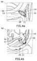
Figure 4a is a schematic view of an embodiment of an ice protection system of an air inlet of an aircraft engine. -
Figure 4b is a schematic view of another embodiment of an ice protection system of another air inlet of an aircraft engine. - The invention proposes a two-phase type (or LHP type)
heat transfer device 10 to collect heat from aheat source 11 operating at a temperature range T1-T2 and to provide heat to acold sink 13. - The
heat transfer device 10 comprise anevaporator 21 close to theheat source 11, acondenser 23 close to thecold sink 13 and liquid andvapor transport lines - We will describe hereinafter a
heat transfer device 10 of an aircraft ice protection system wherein: - the
heat source 11 is located inside the engine nacelle where the temperature range T1-T2 can be set at, for example, 80-250°C; - the
cold sink 13 can be the leading edge of a lifting surface, an engine air inlet or any other part where ice accretion can take place. Eachcold sink 13 can have a particular operating temperature; - the distance between the
heat source 11 and some of the abovementionedcold sinks 13 can be considerable large and subjected to low temperatures and consequently the first working fluid circulating by theliquid line 25 may be subjected to environmental temperatures T3 well below 0°C so that can be frozen, a risk that shall be avoided. A temperature of -35°C can be an exemplary value of T3. - As it is not possible to find a first working fluid suitable, on the one hand, to work at a temperature range of 80-250° and, on the other hand, to be maintained in liquid state in the
liquid line 25 at temperatures well below 0°C, theheat transfer device 10 of the invention has two main distinguishing features regarding the LHP type known devices: - Using a first working fluid having a critical point Tc1 greater than T1 (80°C) and smaller than T2 (250°C) and an acceptable freezing point Tf to meet the requirements of the installation of the
heat transfer device 10. A suitable first working fluid is ammonia that has a critical point Tc1 around +130°C and a freezing point Tf around -40°C. - The
evaporator 21 is arranged inside asaddle 31 configured for avoiding that the temperature of the first working fluid in theevaporator 21 is greater than Tc1. That means that the temperature in the contact surface of thesaddle 31 with theevaporator 21 shall always be in the range T1- Tc1. - In the embodiment illustrated in
Figures 1a and 1b , thesaddle 31 comprises acavity 35 between outer andinner saddle sections cavity 35 is constant so that the fraction evolves (with the density saturation values of the liquid and vapor phases) in order to maintain this value constant. Thecavity 35 has to be designed taking into account the pressure of the second working fluid in the supercritical region which is highly dependent of the charged density. A suitable second working fluid is ammonia. - The
cavity 35 changes the thermal coupling between theheat source 11 and theevaporator 21 and works in two modes depending on the temperature of the heat source 11: - A nominal mode when the temperature T of the
heat source 11 is lesser than the critical point Tc2 of the second working fluid. As illustrated inFig., 2a the heat input Hiev1 at theevaporator 21 is proportional to the heat input Hi1 at the external surface of thesaddle 31 and the heat output Ho1 at thecondenser 23 is proportional to the heat input Hiev1 at the evaporator 21 (for illustration purposes Hi1, Hiev1 and Ho1 are represented with similar dimensions). - A degraded mode when the temperature T of the
heat source 11 is greater than the critical point Tc2 of the second working fluid because the second working fluid has a low conductance in a gaseous state. As illustrated inFig. 2b the heat input Hiev2 at theevaporator 21 is substantially lesser than the heat input Hi2 at the external surface of thesaddle 31. - An ice protection system for an
engine 39 of anaircraft 38 may comprise one or more heat transfer devices for the engine air inlets 40 (seeFigures 3a and 3b ). - As shown in
Figures 4a and 4b an evaporator assembly 32 (comprising an evaporator arranged inside a saddle as explained above) is located over aheat source 11 of theaircraft engine 39 and thecondenser 23 is located over a cold sink. Theevaporator assembly 32 and thecondenser 23 are connected by liquid andvapor lines - In the embodiment shown in
Figure 4a , thecondenser 23 is located over aheat conducting element 43 which is arranged to transmit heat to a specific area of theair inlet 40. - In the embodiment shown in
Figure 4b , thecondenser 23 is located over alip 41 of theair inlet 40. - Although the present invention has been described in connection with various embodiments, it will be appreciated from the specification that various combinations of elements, variations or improvements therein may be made, and are within the scope of the invention as defined by the appended claims.
Claims (11)
- A two-phase type heat transfer device (10) comprising an evaporator (21) collecting heat from a heat source (11), a condenser (23) providing heat to a cold sink (13) and liquid and vapor transport lines (25, 27) of a first working fluid connected to the evaporator (21) and the condenser (23), characterized in that:- the operating temperature of the heat source (11) ranges between T1 and T2, being T1>75°C;- the first working fluid has a critical point Tc1 greater than T1 and smaller than T2 and a freezing point Tf smaller than a minimum environmental external temperature T3 set for the heat transfer device (10);- the evaporator (21) is arranged inside a saddle (31) configured for avoiding that the temperature of the first working fluid in the evaporator (21) is greater than Tc1.
- A two-phase type heat transfer device (10) according to claim 1 wherein T2-T1>100°C.
- A two-phase type heat transfer device (10) according to claim 2, wherein T3=-35°C.
- A two-phase type heat transfer device (10) according to any of claims 1-3, wherein the first working fluid is ammonia.
- A two-phase type heat transfer device (10) according to any of claims 1-4, wherein the saddle (31) comprises a cavity (35) filled with a second working fluid having a critical point Tc2 greater than T1 and smaller than T2 arranged between a saddle outer section (33) and a saddle inner section (37) made of heat conducting material.
- A two-phase type heat transfer device (10) according to claim 5, wherein the second working fluid is ammonia.
- A two-phase type heat transfer device (10) according to any of claims 5-6 wherein the saddle outer section (33) and the saddle inner section (37) are made of aluminium.
- Ice protection system for an aircraft (38) comprising a two-phase type heat transfer device (10) according to any of claims 1-7, wherein the heat source (11) is located inside the nacelle of an aircraft engine (39) and the cold sink (13) is an aircraft part subject to ice accretion.
- Ice protection system for an aircraft (38) according to claim 8 wherein the cold sink (13) is a leading edge of a lifting surface.
- Ice protection system for an aircraft (38) according to claim 8 wherein the cold sink (13) is an engine air inlet (40).
- Aircraft (38) comprising a two-phase type heat transfer device (10) according to any of claims 1-7, wherein the evaporator (21) is located over a heat conducting element of the aircraft (38) and the condenser (23) is located over an aircraft part subject to ice accretion.
Priority Applications (3)
| Application Number | Priority Date | Filing Date | Title |
|---|---|---|---|
| ES15382517T ES2716116T3 (en) | 2015-10-21 | 2015-10-21 | A two-phase type heat transfer device for heat sources operating in a wide range of temperatures |
| EP15382517.9A EP3159647B1 (en) | 2015-10-21 | 2015-10-21 | A two-phase type heat transfer device for heat sources operating at a wide temperature range |
| US15/331,232 US10717535B2 (en) | 2015-10-21 | 2016-10-21 | Two-phase type heat transfer device for heat sources operating at a wide temperature range |
Applications Claiming Priority (1)
| Application Number | Priority Date | Filing Date | Title |
|---|---|---|---|
| EP15382517.9A EP3159647B1 (en) | 2015-10-21 | 2015-10-21 | A two-phase type heat transfer device for heat sources operating at a wide temperature range |
Publications (2)
| Publication Number | Publication Date |
|---|---|
| EP3159647A1 true EP3159647A1 (en) | 2017-04-26 |
| EP3159647B1 EP3159647B1 (en) | 2018-12-12 |
Family
ID=54365177
Family Applications (1)
| Application Number | Title | Priority Date | Filing Date |
|---|---|---|---|
| EP15382517.9A Active EP3159647B1 (en) | 2015-10-21 | 2015-10-21 | A two-phase type heat transfer device for heat sources operating at a wide temperature range |
Country Status (3)
| Country | Link |
|---|---|
| US (1) | US10717535B2 (en) |
| EP (1) | EP3159647B1 (en) |
| ES (1) | ES2716116T3 (en) |
Cited By (1)
| Publication number | Priority date | Publication date | Assignee | Title |
|---|---|---|---|---|
| CN109823510A (en) * | 2019-03-06 | 2019-05-31 | 中南大学 | Hypersonic vehicle and its thermal protection structure and coolant circulation system |
Families Citing this family (2)
| Publication number | Priority date | Publication date | Assignee | Title |
|---|---|---|---|---|
| FR3077268A1 (en) * | 2018-01-26 | 2019-08-02 | Airbus Operations | DEVICE FOR DEFROSTING A CONFIGURED SURFACE TO NOT GENERATE ELECTROMAGNETIC INTERFERENCE |
| US12397915B2 (en) | 2022-09-02 | 2025-08-26 | General Electric Company | Ice protection systems for aircraft fueled by hydrogen |
Citations (14)
| Publication number | Priority date | Publication date | Assignee | Title |
|---|---|---|---|---|
| DE2724309A1 (en) * | 1977-05-28 | 1978-11-30 | Dornier System Gmbh | DEVICE FOR ADJUSTABLE TEMPERATURE TRANSFER |
| GB2136880A (en) * | 1983-03-18 | 1984-09-26 | Rolls Royce | Anti-icing of gas turbine engine air intakes |
| JPS62138683A (en) * | 1985-12-11 | 1987-06-22 | Hitachi Ltd | Exhaust heat amount control device |
| DE4108981A1 (en) * | 1991-03-19 | 1992-10-01 | Siemens Ag | Cooling circuit for electronic equipment - regulates by either temp. or pressure control with ventilator or liq. cooling for condenser |
| US6938679B1 (en) * | 1998-09-15 | 2005-09-06 | The Boeing Company | Heat transport apparatus |
| US7004240B1 (en) * | 2002-06-24 | 2006-02-28 | Swales & Associates, Inc. | Heat transport system |
| EP1884625A2 (en) * | 2006-07-28 | 2008-02-06 | General Electric Company | Heat transfer system and method for turbine engine using heat pipes |
| EP2157391A1 (en) | 2007-06-15 | 2010-02-24 | Asahi Kasei Fibers Corporation | Loop heat pipe type heat transfer device |
| US7882888B1 (en) * | 2005-02-23 | 2011-02-08 | Swales & Associates, Inc. | Two-phase heat transfer system including a thermal capacitance device |
| US20110113791A1 (en) * | 2009-11-17 | 2011-05-19 | Empire Technology Development Llc | Thermal management with electrocaloric effect layer |
| US20130029936A1 (en) | 2002-03-28 | 2013-01-31 | Jae Hyun Kim | Inclusion Compounds of Fumagillol Derivative or its Salt, and Pharmaceutical Compositions Comprising the Same |
| EP2567894A1 (en) * | 2011-09-07 | 2013-03-13 | Bell Helicopter Textron Inc. | System for heat dissipation from an internal actuator in a rotor blade |
| US8550150B2 (en) | 2009-10-16 | 2013-10-08 | Foxconn Technology Co., Ltd. | Loop heat pipe |
| US20140116652A1 (en) * | 2012-10-26 | 2014-05-01 | Bell Helicopter Textron Inc. | Passive Cooling of Transmission Using Mast Mounted Heat Pipes |
Family Cites Families (4)
| Publication number | Priority date | Publication date | Assignee | Title |
|---|---|---|---|---|
| US3831664A (en) * | 1973-11-07 | 1974-08-27 | Boeing Co | Heat pipe interfaces |
| US5507150A (en) * | 1994-02-04 | 1996-04-16 | Texas Instruments Incorporated | Expendable liquid thermal management system |
| US5548971A (en) * | 1995-06-14 | 1996-08-27 | Rocky Research | Method for use of liquid/vapor ammonia absorption systems in unitary HVAC systems |
| US9422063B2 (en) * | 2013-05-31 | 2016-08-23 | General Electric Company | Cooled cooling air system for a gas turbine |
-
2015
- 2015-10-21 EP EP15382517.9A patent/EP3159647B1/en active Active
- 2015-10-21 ES ES15382517T patent/ES2716116T3/en active Active
-
2016
- 2016-10-21 US US15/331,232 patent/US10717535B2/en active Active
Patent Citations (14)
| Publication number | Priority date | Publication date | Assignee | Title |
|---|---|---|---|---|
| DE2724309A1 (en) * | 1977-05-28 | 1978-11-30 | Dornier System Gmbh | DEVICE FOR ADJUSTABLE TEMPERATURE TRANSFER |
| GB2136880A (en) * | 1983-03-18 | 1984-09-26 | Rolls Royce | Anti-icing of gas turbine engine air intakes |
| JPS62138683A (en) * | 1985-12-11 | 1987-06-22 | Hitachi Ltd | Exhaust heat amount control device |
| DE4108981A1 (en) * | 1991-03-19 | 1992-10-01 | Siemens Ag | Cooling circuit for electronic equipment - regulates by either temp. or pressure control with ventilator or liq. cooling for condenser |
| US6938679B1 (en) * | 1998-09-15 | 2005-09-06 | The Boeing Company | Heat transport apparatus |
| US20130029936A1 (en) | 2002-03-28 | 2013-01-31 | Jae Hyun Kim | Inclusion Compounds of Fumagillol Derivative or its Salt, and Pharmaceutical Compositions Comprising the Same |
| US7004240B1 (en) * | 2002-06-24 | 2006-02-28 | Swales & Associates, Inc. | Heat transport system |
| US7882888B1 (en) * | 2005-02-23 | 2011-02-08 | Swales & Associates, Inc. | Two-phase heat transfer system including a thermal capacitance device |
| EP1884625A2 (en) * | 2006-07-28 | 2008-02-06 | General Electric Company | Heat transfer system and method for turbine engine using heat pipes |
| EP2157391A1 (en) | 2007-06-15 | 2010-02-24 | Asahi Kasei Fibers Corporation | Loop heat pipe type heat transfer device |
| US8550150B2 (en) | 2009-10-16 | 2013-10-08 | Foxconn Technology Co., Ltd. | Loop heat pipe |
| US20110113791A1 (en) * | 2009-11-17 | 2011-05-19 | Empire Technology Development Llc | Thermal management with electrocaloric effect layer |
| EP2567894A1 (en) * | 2011-09-07 | 2013-03-13 | Bell Helicopter Textron Inc. | System for heat dissipation from an internal actuator in a rotor blade |
| US20140116652A1 (en) * | 2012-10-26 | 2014-05-01 | Bell Helicopter Textron Inc. | Passive Cooling of Transmission Using Mast Mounted Heat Pipes |
Cited By (1)
| Publication number | Priority date | Publication date | Assignee | Title |
|---|---|---|---|---|
| CN109823510A (en) * | 2019-03-06 | 2019-05-31 | 中南大学 | Hypersonic vehicle and its thermal protection structure and coolant circulation system |
Also Published As
| Publication number | Publication date |
|---|---|
| US10717535B2 (en) | 2020-07-21 |
| ES2716116T3 (en) | 2019-06-10 |
| EP3159647B1 (en) | 2018-12-12 |
| US20170113804A1 (en) | 2017-04-27 |
Similar Documents
| Publication | Publication Date | Title |
|---|---|---|
| Su et al. | A review of loop heat pipes for aircraft anti-icing applications | |
| US20180340739A1 (en) | Temperature Actuated Capillary Valve for Loop Heat Pipe System | |
| EP3558820B1 (en) | Systems, methods, and apparatus for passive cooling of uavs | |
| US20150068703A1 (en) | Thermal management system and method of assembling the same | |
| EP2347166B1 (en) | Removing non-condensable gas from a subambient cooling system | |
| CN103786886B (en) | Ice preventing and removing system for aircraft wing | |
| EP2203696B1 (en) | Cooling system | |
| US10399692B2 (en) | Aircraft fuel system with heating of stored fuel | |
| US10364043B2 (en) | Passive aircraft cooling systems and methods | |
| TW200306402A (en) | Loop heat pipe method and apparatus | |
| EP3159647B1 (en) | A two-phase type heat transfer device for heat sources operating at a wide temperature range | |
| US20180229850A1 (en) | Anti-icing system for gas turbine engine | |
| CN101590913A (en) | Anti-icing and de-icing method of civil aircraft using loop heat pipe | |
| CN105539860A (en) | Heat management device suitable for large heat flux during long endurance | |
| EP4029785B1 (en) | Aircraft with a fuel cell and a structure having a tank containing a heat-transfer fluid ensuring the cooling of the fuel cell | |
| US20150207465A1 (en) | System and method to remove heat from a power amplifier | |
| Rassamakin et al. | Thermal performance of aluminium grooved heat pipes | |
| US10352623B2 (en) | Diphasic cooling loop with satellite evaporators | |
| EP3095704B1 (en) | Heat recovery system, in particular for use on aircraft, using a two-phase fluid circuit | |
| US10544995B2 (en) | Capillary pump assisted heat pipe | |
| Ogushi et al. | Heat transport characteristics of flexible looped heat pipe under micro‐gravity condition | |
| EP3816564A1 (en) | Cooling device for cooling electronic components | |
| US20200173699A1 (en) | Device and Method for Increasing the Thermal Output of a Heat Source | |
| Chang | Experimental investigation on the effection of flow regulator in a multiple evaporators/condensers loop heat pipe with plastic porous structure | |
| Zhang et al. | Parametric study of a novel gravity assisted loop heat pipe (galhp) with composite mesh-screen wick structure |
Legal Events
| Date | Code | Title | Description |
|---|---|---|---|
| PUAI | Public reference made under article 153(3) epc to a published international application that has entered the european phase |
Free format text: ORIGINAL CODE: 0009012 |
|
| STAA | Information on the status of an ep patent application or granted ep patent |
Free format text: STATUS: THE APPLICATION HAS BEEN PUBLISHED |
|
| AK | Designated contracting states |
Kind code of ref document: A1 Designated state(s): AL AT BE BG CH CY CZ DE DK EE ES FI FR GB GR HR HU IE IS IT LI LT LU LV MC MK MT NL NO PL PT RO RS SE SI SK SM TR |
|
| AX | Request for extension of the european patent |
Extension state: BA ME |
|
| STAA | Information on the status of an ep patent application or granted ep patent |
Free format text: STATUS: REQUEST FOR EXAMINATION WAS MADE |
|
| 17P | Request for examination filed |
Effective date: 20171026 |
|
| RBV | Designated contracting states (corrected) |
Designated state(s): AL AT BE BG CH CY CZ DE DK EE ES FI FR GB GR HR HU IE IS IT LI LT LU LV MC MK MT NL NO PL PT RO RS SE SI SK SM TR |
|
| GRAP | Despatch of communication of intention to grant a patent |
Free format text: ORIGINAL CODE: EPIDOSNIGR1 |
|
| STAA | Information on the status of an ep patent application or granted ep patent |
Free format text: STATUS: GRANT OF PATENT IS INTENDED |
|
| RIC1 | Information provided on ipc code assigned before grant |
Ipc: B64D 15/02 20060101ALI20180508BHEP Ipc: F28D 15/06 20060101ALI20180508BHEP Ipc: F28F 13/00 20060101ALN20180508BHEP Ipc: F28D 15/02 20060101AFI20180508BHEP Ipc: F28F 23/00 20060101ALN20180508BHEP Ipc: F28F 13/18 20060101ALI20180508BHEP |
|
| INTG | Intention to grant announced |
Effective date: 20180530 |
|
| GRAS | Grant fee paid |
Free format text: ORIGINAL CODE: EPIDOSNIGR3 |
|
| GRAA | (expected) grant |
Free format text: ORIGINAL CODE: 0009210 |
|
| STAA | Information on the status of an ep patent application or granted ep patent |
Free format text: STATUS: THE PATENT HAS BEEN GRANTED |
|
| AK | Designated contracting states |
Kind code of ref document: B1 Designated state(s): AL AT BE BG CH CY CZ DE DK EE ES FI FR GB GR HR HU IE IS IT LI LT LU LV MC MK MT NL NO PL PT RO RS SE SI SK SM TR |
|
| REG | Reference to a national code |
Ref country code: GB Ref legal event code: FG4D |
|
| REG | Reference to a national code |
Ref country code: CH Ref legal event code: EP |
|
| REG | Reference to a national code |
Ref country code: AT Ref legal event code: REF Ref document number: 1076580 Country of ref document: AT Kind code of ref document: T Effective date: 20181215 |
|
| REG | Reference to a national code |
Ref country code: DE Ref legal event code: R096 Ref document number: 602015021199 Country of ref document: DE |
|
| REG | Reference to a national code |
Ref country code: IE Ref legal event code: FG4D |
|
| REG | Reference to a national code |
Ref country code: NL Ref legal event code: MP Effective date: 20181212 |
|
| REG | Reference to a national code |
Ref country code: LT Ref legal event code: MG4D |
|
| PG25 | Lapsed in a contracting state [announced via postgrant information from national office to epo] |
Ref country code: FI Free format text: LAPSE BECAUSE OF FAILURE TO SUBMIT A TRANSLATION OF THE DESCRIPTION OR TO PAY THE FEE WITHIN THE PRESCRIBED TIME-LIMIT Effective date: 20181212 Ref country code: HR Free format text: LAPSE BECAUSE OF FAILURE TO SUBMIT A TRANSLATION OF THE DESCRIPTION OR TO PAY THE FEE WITHIN THE PRESCRIBED TIME-LIMIT Effective date: 20181212 Ref country code: LV Free format text: LAPSE BECAUSE OF FAILURE TO SUBMIT A TRANSLATION OF THE DESCRIPTION OR TO PAY THE FEE WITHIN THE PRESCRIBED TIME-LIMIT Effective date: 20181212 Ref country code: NO Free format text: LAPSE BECAUSE OF FAILURE TO SUBMIT A TRANSLATION OF THE DESCRIPTION OR TO PAY THE FEE WITHIN THE PRESCRIBED TIME-LIMIT Effective date: 20190312 Ref country code: BG Free format text: LAPSE BECAUSE OF FAILURE TO SUBMIT A TRANSLATION OF THE DESCRIPTION OR TO PAY THE FEE WITHIN THE PRESCRIBED TIME-LIMIT Effective date: 20190312 Ref country code: LT Free format text: LAPSE BECAUSE OF FAILURE TO SUBMIT A TRANSLATION OF THE DESCRIPTION OR TO PAY THE FEE WITHIN THE PRESCRIBED TIME-LIMIT Effective date: 20181212 |
|
| REG | Reference to a national code |
Ref country code: AT Ref legal event code: MK05 Ref document number: 1076580 Country of ref document: AT Kind code of ref document: T Effective date: 20181212 |
|
| PG25 | Lapsed in a contracting state [announced via postgrant information from national office to epo] |
Ref country code: AL Free format text: LAPSE BECAUSE OF FAILURE TO SUBMIT A TRANSLATION OF THE DESCRIPTION OR TO PAY THE FEE WITHIN THE PRESCRIBED TIME-LIMIT Effective date: 20181212 Ref country code: GR Free format text: LAPSE BECAUSE OF FAILURE TO SUBMIT A TRANSLATION OF THE DESCRIPTION OR TO PAY THE FEE WITHIN THE PRESCRIBED TIME-LIMIT Effective date: 20190313 Ref country code: SE Free format text: LAPSE BECAUSE OF FAILURE TO SUBMIT A TRANSLATION OF THE DESCRIPTION OR TO PAY THE FEE WITHIN THE PRESCRIBED TIME-LIMIT Effective date: 20181212 Ref country code: RS Free format text: LAPSE BECAUSE OF FAILURE TO SUBMIT A TRANSLATION OF THE DESCRIPTION OR TO PAY THE FEE WITHIN THE PRESCRIBED TIME-LIMIT Effective date: 20181212 |
|
| REG | Reference to a national code |
Ref country code: ES Ref legal event code: FG2A Ref document number: 2716116 Country of ref document: ES Kind code of ref document: T3 Effective date: 20190610 |
|
| PG25 | Lapsed in a contracting state [announced via postgrant information from national office to epo] |
Ref country code: NL Free format text: LAPSE BECAUSE OF FAILURE TO SUBMIT A TRANSLATION OF THE DESCRIPTION OR TO PAY THE FEE WITHIN THE PRESCRIBED TIME-LIMIT Effective date: 20181212 |
|
| PG25 | Lapsed in a contracting state [announced via postgrant information from national office to epo] |
Ref country code: IT Free format text: LAPSE BECAUSE OF FAILURE TO SUBMIT A TRANSLATION OF THE DESCRIPTION OR TO PAY THE FEE WITHIN THE PRESCRIBED TIME-LIMIT Effective date: 20181212 Ref country code: CZ Free format text: LAPSE BECAUSE OF FAILURE TO SUBMIT A TRANSLATION OF THE DESCRIPTION OR TO PAY THE FEE WITHIN THE PRESCRIBED TIME-LIMIT Effective date: 20181212 Ref country code: PT Free format text: LAPSE BECAUSE OF FAILURE TO SUBMIT A TRANSLATION OF THE DESCRIPTION OR TO PAY THE FEE WITHIN THE PRESCRIBED TIME-LIMIT Effective date: 20190412 Ref country code: PL Free format text: LAPSE BECAUSE OF FAILURE TO SUBMIT A TRANSLATION OF THE DESCRIPTION OR TO PAY THE FEE WITHIN THE PRESCRIBED TIME-LIMIT Effective date: 20181212 |
|
| PG25 | Lapsed in a contracting state [announced via postgrant information from national office to epo] |
Ref country code: EE Free format text: LAPSE BECAUSE OF FAILURE TO SUBMIT A TRANSLATION OF THE DESCRIPTION OR TO PAY THE FEE WITHIN THE PRESCRIBED TIME-LIMIT Effective date: 20181212 Ref country code: SM Free format text: LAPSE BECAUSE OF FAILURE TO SUBMIT A TRANSLATION OF THE DESCRIPTION OR TO PAY THE FEE WITHIN THE PRESCRIBED TIME-LIMIT Effective date: 20181212 Ref country code: RO Free format text: LAPSE BECAUSE OF FAILURE TO SUBMIT A TRANSLATION OF THE DESCRIPTION OR TO PAY THE FEE WITHIN THE PRESCRIBED TIME-LIMIT Effective date: 20181212 Ref country code: SK Free format text: LAPSE BECAUSE OF FAILURE TO SUBMIT A TRANSLATION OF THE DESCRIPTION OR TO PAY THE FEE WITHIN THE PRESCRIBED TIME-LIMIT Effective date: 20181212 Ref country code: IS Free format text: LAPSE BECAUSE OF FAILURE TO SUBMIT A TRANSLATION OF THE DESCRIPTION OR TO PAY THE FEE WITHIN THE PRESCRIBED TIME-LIMIT Effective date: 20190412 |
|
| REG | Reference to a national code |
Ref country code: DE Ref legal event code: R097 Ref document number: 602015021199 Country of ref document: DE |
|
| PLBE | No opposition filed within time limit |
Free format text: ORIGINAL CODE: 0009261 |
|
| STAA | Information on the status of an ep patent application or granted ep patent |
Free format text: STATUS: NO OPPOSITION FILED WITHIN TIME LIMIT |
|
| PG25 | Lapsed in a contracting state [announced via postgrant information from national office to epo] |
Ref country code: DK Free format text: LAPSE BECAUSE OF FAILURE TO SUBMIT A TRANSLATION OF THE DESCRIPTION OR TO PAY THE FEE WITHIN THE PRESCRIBED TIME-LIMIT Effective date: 20181212 Ref country code: SI Free format text: LAPSE BECAUSE OF FAILURE TO SUBMIT A TRANSLATION OF THE DESCRIPTION OR TO PAY THE FEE WITHIN THE PRESCRIBED TIME-LIMIT Effective date: 20181212 Ref country code: AT Free format text: LAPSE BECAUSE OF FAILURE TO SUBMIT A TRANSLATION OF THE DESCRIPTION OR TO PAY THE FEE WITHIN THE PRESCRIBED TIME-LIMIT Effective date: 20181212 |
|
| 26N | No opposition filed |
Effective date: 20190913 |
|
| PG25 | Lapsed in a contracting state [announced via postgrant information from national office to epo] |
Ref country code: MC Free format text: LAPSE BECAUSE OF FAILURE TO SUBMIT A TRANSLATION OF THE DESCRIPTION OR TO PAY THE FEE WITHIN THE PRESCRIBED TIME-LIMIT Effective date: 20181212 |
|
| REG | Reference to a national code |
Ref country code: CH Ref legal event code: PL |
|
| PG25 | Lapsed in a contracting state [announced via postgrant information from national office to epo] |
Ref country code: LI Free format text: LAPSE BECAUSE OF NON-PAYMENT OF DUE FEES Effective date: 20191031 Ref country code: LU Free format text: LAPSE BECAUSE OF NON-PAYMENT OF DUE FEES Effective date: 20191021 Ref country code: CH Free format text: LAPSE BECAUSE OF NON-PAYMENT OF DUE FEES Effective date: 20191031 |
|
| REG | Reference to a national code |
Ref country code: BE Ref legal event code: MM Effective date: 20191031 |
|
| PG25 | Lapsed in a contracting state [announced via postgrant information from national office to epo] |
Ref country code: BE Free format text: LAPSE BECAUSE OF NON-PAYMENT OF DUE FEES Effective date: 20191031 |
|
| PG25 | Lapsed in a contracting state [announced via postgrant information from national office to epo] |
Ref country code: IE Free format text: LAPSE BECAUSE OF NON-PAYMENT OF DUE FEES Effective date: 20191021 |
|
| PGFP | Annual fee paid to national office [announced via postgrant information from national office to epo] |
Ref country code: TR Payment date: 20201020 Year of fee payment: 6 |
|
| PG25 | Lapsed in a contracting state [announced via postgrant information from national office to epo] |
Ref country code: CY Free format text: LAPSE BECAUSE OF FAILURE TO SUBMIT A TRANSLATION OF THE DESCRIPTION OR TO PAY THE FEE WITHIN THE PRESCRIBED TIME-LIMIT Effective date: 20181212 |
|
| PG25 | Lapsed in a contracting state [announced via postgrant information from national office to epo] |
Ref country code: MT Free format text: LAPSE BECAUSE OF FAILURE TO SUBMIT A TRANSLATION OF THE DESCRIPTION OR TO PAY THE FEE WITHIN THE PRESCRIBED TIME-LIMIT Effective date: 20181212 Ref country code: HU Free format text: LAPSE BECAUSE OF FAILURE TO SUBMIT A TRANSLATION OF THE DESCRIPTION OR TO PAY THE FEE WITHIN THE PRESCRIBED TIME-LIMIT; INVALID AB INITIO Effective date: 20151021 |
|
| PG25 | Lapsed in a contracting state [announced via postgrant information from national office to epo] |
Ref country code: MK Free format text: LAPSE BECAUSE OF FAILURE TO SUBMIT A TRANSLATION OF THE DESCRIPTION OR TO PAY THE FEE WITHIN THE PRESCRIBED TIME-LIMIT Effective date: 20181212 |
|
| PG25 | Lapsed in a contracting state [announced via postgrant information from national office to epo] |
Ref country code: TR Free format text: LAPSE BECAUSE OF NON-PAYMENT OF DUE FEES Effective date: 20211021 |
|
| PGFP | Annual fee paid to national office [announced via postgrant information from national office to epo] |
Ref country code: DE Payment date: 20251021 Year of fee payment: 11 |
|
| PGFP | Annual fee paid to national office [announced via postgrant information from national office to epo] |
Ref country code: GB Payment date: 20251022 Year of fee payment: 11 |
|
| PGFP | Annual fee paid to national office [announced via postgrant information from national office to epo] |
Ref country code: FR Payment date: 20251030 Year of fee payment: 11 |
|
| PGFP | Annual fee paid to national office [announced via postgrant information from national office to epo] |
Ref country code: ES Payment date: 20251210 Year of fee payment: 11 |