EP3159512A1 - Improved crosswind performance aircraft engine spinner - Google Patents
Improved crosswind performance aircraft engine spinner Download PDFInfo
- Publication number
- EP3159512A1 EP3159512A1 EP16194478.0A EP16194478A EP3159512A1 EP 3159512 A1 EP3159512 A1 EP 3159512A1 EP 16194478 A EP16194478 A EP 16194478A EP 3159512 A1 EP3159512 A1 EP 3159512A1
- Authority
- EP
- European Patent Office
- Prior art keywords
- spinner
- section
- aspect ratio
- cross
- baseline
- Prior art date
- Legal status (The legal status is an assumption and is not a legal conclusion. Google has not performed a legal analysis and makes no representation as to the accuracy of the status listed.)
- Granted
Links
Images

Classifications
-
- F—MECHANICAL ENGINEERING; LIGHTING; HEATING; WEAPONS; BLASTING
- F04—POSITIVE - DISPLACEMENT MACHINES FOR LIQUIDS; PUMPS FOR LIQUIDS OR ELASTIC FLUIDS
- F04D—NON-POSITIVE-DISPLACEMENT PUMPS
- F04D29/00—Details, component parts, or accessories
- F04D29/26—Rotors specially for elastic fluids
- F04D29/32—Rotors specially for elastic fluids for axial flow pumps
- F04D29/325—Rotors specially for elastic fluids for axial flow pumps for axial flow fans
- F04D29/326—Rotors specially for elastic fluids for axial flow pumps for axial flow fans comprising a rotating shroud
-
- B—PERFORMING OPERATIONS; TRANSPORTING
- B64—AIRCRAFT; AVIATION; COSMONAUTICS
- B64D—EQUIPMENT FOR FITTING IN OR TO AIRCRAFT; FLIGHT SUITS; PARACHUTES; ARRANGEMENT OR MOUNTING OF POWER PLANTS OR PROPULSION TRANSMISSIONS IN AIRCRAFT
- B64D33/00—Arrangement in aircraft of power plant parts or auxiliaries not otherwise provided for
- B64D33/02—Arrangement in aircraft of power plant parts or auxiliaries not otherwise provided for of combustion air intakes
-
- F—MECHANICAL ENGINEERING; LIGHTING; HEATING; WEAPONS; BLASTING
- F01—MACHINES OR ENGINES IN GENERAL; ENGINE PLANTS IN GENERAL; STEAM ENGINES
- F01D—NON-POSITIVE DISPLACEMENT MACHINES OR ENGINES, e.g. STEAM TURBINES
- F01D25/00—Component parts, details, or accessories, not provided for in, or of interest apart from, other groups
- F01D25/24—Casings; Casing parts, e.g. diaphragms, casing fastenings
-
- F—MECHANICAL ENGINEERING; LIGHTING; HEATING; WEAPONS; BLASTING
- F01—MACHINES OR ENGINES IN GENERAL; ENGINE PLANTS IN GENERAL; STEAM ENGINES
- F01D—NON-POSITIVE DISPLACEMENT MACHINES OR ENGINES, e.g. STEAM TURBINES
- F01D5/00—Blades; Blade-carrying members; Heating, heat-insulating, cooling or antivibration means on the blades or the members
- F01D5/02—Blade-carrying members, e.g. rotors
-
- F—MECHANICAL ENGINEERING; LIGHTING; HEATING; WEAPONS; BLASTING
- F02—COMBUSTION ENGINES; HOT-GAS OR COMBUSTION-PRODUCT ENGINE PLANTS
- F02C—GAS-TURBINE PLANTS; AIR INTAKES FOR JET-PROPULSION PLANTS; CONTROLLING FUEL SUPPLY IN AIR-BREATHING JET-PROPULSION PLANTS
- F02C7/00—Features, components parts, details or accessories, not provided for in, or of interest apart form groups F02C1/00 - F02C6/00; Air intakes for jet-propulsion plants
- F02C7/04—Air intakes for gas-turbine plants or jet-propulsion plants
-
- B—PERFORMING OPERATIONS; TRANSPORTING
- B64—AIRCRAFT; AVIATION; COSMONAUTICS
- B64C—AEROPLANES; HELICOPTERS
- B64C11/00—Propellers, e.g. of ducted type; Features common to propellers and rotors for rotorcraft
- B64C11/02—Hub construction
- B64C11/14—Spinners
-
- B—PERFORMING OPERATIONS; TRANSPORTING
- B64—AIRCRAFT; AVIATION; COSMONAUTICS
- B64D—EQUIPMENT FOR FITTING IN OR TO AIRCRAFT; FLIGHT SUITS; PARACHUTES; ARRANGEMENT OR MOUNTING OF POWER PLANTS OR PROPULSION TRANSMISSIONS IN AIRCRAFT
- B64D33/00—Arrangement in aircraft of power plant parts or auxiliaries not otherwise provided for
- B64D33/02—Arrangement in aircraft of power plant parts or auxiliaries not otherwise provided for of combustion air intakes
- B64D2033/0266—Arrangement in aircraft of power plant parts or auxiliaries not otherwise provided for of combustion air intakes specially adapted for particular type of power plants
- B64D2033/0286—Arrangement in aircraft of power plant parts or auxiliaries not otherwise provided for of combustion air intakes specially adapted for particular type of power plants for turbofan engines
-
- F—MECHANICAL ENGINEERING; LIGHTING; HEATING; WEAPONS; BLASTING
- F05—INDEXING SCHEMES RELATING TO ENGINES OR PUMPS IN VARIOUS SUBCLASSES OF CLASSES F01-F04
- F05D—INDEXING SCHEME FOR ASPECTS RELATING TO NON-POSITIVE-DISPLACEMENT MACHINES OR ENGINES, GAS-TURBINES OR JET-PROPULSION PLANTS
- F05D2220/00—Application
- F05D2220/30—Application in turbines
- F05D2220/32—Application in turbines in gas turbines
- F05D2220/323—Application in turbines in gas turbines for aircraft propulsion, e.g. jet engines
-
- F—MECHANICAL ENGINEERING; LIGHTING; HEATING; WEAPONS; BLASTING
- F05—INDEXING SCHEMES RELATING TO ENGINES OR PUMPS IN VARIOUS SUBCLASSES OF CLASSES F01-F04
- F05D—INDEXING SCHEME FOR ASPECTS RELATING TO NON-POSITIVE-DISPLACEMENT MACHINES OR ENGINES, GAS-TURBINES OR JET-PROPULSION PLANTS
- F05D2240/00—Components
- F05D2240/20—Rotors
-
- F—MECHANICAL ENGINEERING; LIGHTING; HEATING; WEAPONS; BLASTING
- F05—INDEXING SCHEMES RELATING TO ENGINES OR PUMPS IN VARIOUS SUBCLASSES OF CLASSES F01-F04
- F05D—INDEXING SCHEME FOR ASPECTS RELATING TO NON-POSITIVE-DISPLACEMENT MACHINES OR ENGINES, GAS-TURBINES OR JET-PROPULSION PLANTS
- F05D2250/00—Geometry
- F05D2250/20—Three-dimensional
- F05D2250/23—Three-dimensional prismatic
- F05D2250/232—Three-dimensional prismatic conical
-
- F—MECHANICAL ENGINEERING; LIGHTING; HEATING; WEAPONS; BLASTING
- F05—INDEXING SCHEMES RELATING TO ENGINES OR PUMPS IN VARIOUS SUBCLASSES OF CLASSES F01-F04
- F05D—INDEXING SCHEME FOR ASPECTS RELATING TO NON-POSITIVE-DISPLACEMENT MACHINES OR ENGINES, GAS-TURBINES OR JET-PROPULSION PLANTS
- F05D2250/00—Geometry
- F05D2250/50—Inlet or outlet
- F05D2250/51—Inlet
-
- Y—GENERAL TAGGING OF NEW TECHNOLOGICAL DEVELOPMENTS; GENERAL TAGGING OF CROSS-SECTIONAL TECHNOLOGIES SPANNING OVER SEVERAL SECTIONS OF THE IPC; TECHNICAL SUBJECTS COVERED BY FORMER USPC CROSS-REFERENCE ART COLLECTIONS [XRACs] AND DIGESTS
- Y02—TECHNOLOGIES OR APPLICATIONS FOR MITIGATION OR ADAPTATION AGAINST CLIMATE CHANGE
- Y02T—CLIMATE CHANGE MITIGATION TECHNOLOGIES RELATED TO TRANSPORTATION
- Y02T50/00—Aeronautics or air transport
- Y02T50/60—Efficient propulsion technologies, e.g. for aircraft
Definitions
- the present invention relates to aircraft engine spinners and, more particularly, to shape and size of the spinners.
- a gas turbine engine typically includes a fan section, a compressor section, a combustor section and a turbine section. Air entering the compressor section is compressed and delivered into the combustor section where it is mixed with fuel and ignited to generate a high-speed exhaust gas flow. The high-speed exhaust gas flow expands through the turbine section to drive the compressor and a fan in the fan section.
- the compressor section typically includes low and high pressure compressors, and the turbine section includes low and high pressure turbines.
- the fan section includes an inlet which in part may be formed by a nacelle surrounding the fan section and leads to a fan in the fan section.
- Jet engine operations in crosswinds and at high angles of attack can be significantly restricted by fan blade aeromechanics and operability limits.
- Airframers seek to minimize or eliminate such engine operational restrictions in order to prevent having to impose aircraft operational limits.
- Conventional methods of improving inlet performance in crosswinds or at high angles of attack have involved shape changes to the inlet geometry. Such changes often negatively affect the performance at other critical operating points, such as cruise. It is, thus, highly desirable to improve inlet performance in crosswinds without substantially negatively affecting cruise performance.
- An aircraft gas turbine engine spinner for mounting to a rotor of an aircraft gas turbine engine.
- the spinner including a conical upstream or forward spinner section extending aftwardly from a spinner tip followed by a curved downstream or aft spinner section, the spinner circumscribed about an axial centerline axis, the spinner having a spinner aspect ratio greater than about 1.8, and wherein the spinner aspect ratio is an axial distance between the spinner tip and a spinner end divided by a radial distance from the engine axial centerline axis to an outer surface of the spinner.
- the spinner aspect ratio may be in a range of about 2.0 - 2.2 or about 2.2 - 2.8.
- the aft spinner section may be substantially tangential to platform leading edges of platforms of the fan blades.
- the aft spinner section may have a cambered or an elliptical axially curved cross-section.
- the forward spinner section may be substantially tangential to the aft spinner section at their intersection.
- the spinner may include a spinner axial cross-section having a longer spinner axial distance as compared to a baseline axial distance of a baseline cross-section and the spinner aspect ratio greater than a baseline aspect ratio of the baseline cross-section.
- An aircraft gas turbine engine fan assembly includes a fan casing surrounding an array of fan blades mounted to and extending radially outwardly from a rotor circumscribed about a centerline axis, a nacelle surrounding the fan casing, a spinner circumscribing the centerline axis and mounted to the rotor, the spinner including a conical upstream or forward spinner section extending aftwardly from a spinner tip followed by a curved downstream or aft spinner section, the spinner circumscribed about a centerline axis, the spinner having a spinner aspect ratio greater than about 1.8, and wherein the spinner aspect ratio is an axial distance between the spinner tip and a spinner end divided by a radial distance from the engine axial centerline axis to an outer surface of the spinner.
- the assembly may further include a spinner axial cross-section having a longer spinner axial distance as compared to a baseline axial distance of a baseline cross-section, the spinner aspect ratio greater than a baseline aspect ratio of the baseline cross-section, the spinner axial cross-section shaped and sized to improve crosswind and/or high angle of attack performance of the assembly over that of the baseline cross-section.
- the spinner axial cross-section may be sized and shaped at a station or axial distance along the centerline axis to change aerodynamics of flow through the inlet to create improvements in crosswind or high angle of attack performance relative to that of the baseline cross-section.
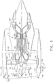
- FIG. 1 Illustrated in FIG. 1 is an exemplary embodiment of an aircraft gas turbine engine 10 including a fan assembly 12 and a core engine 14 rotatable about a longitudinally extending engine axial centerline axis 30.
- the fan assembly 12 includes a fan casing 16 surrounding an array of fan blades 18 extending radially outwardly from a rotor 20.
- Fan blade airfoils 33 extend radially outwardly from the fan blade platform 35 of each of the fan blades 18.
- the blades and airfoils may be mounted on a BLISK of the rotor.
- the core engine 14 includes a high-pressure compressor 22, a combustor 24, a high pressure turbine 26.
- a low pressure turbine 28 drives the fan blades 18.
- the engine 10 is mounted within a nacelle 32 connected to the fan casing 16 of the engine 10.
- the fan casing 16 is surrounded by and disposed within the nacelle 32 and circumscribed about the fan blades 18 and supports the fan assembly 12 through a plurality of circumferentially spaced struts 34.
- the nacelle 32 includes an annular inlet 25 attached to a forward casing flange 38 on the fan casing 16 by a plurality of circumferentially spaced fasteners, such as bolts or the like.
- the nacelle 32 typically includes radially spaced apart annular inner and outer barrels 40, 42.
- a fan inlet flowpath 66 extends downstream from an inlet leading edge 68 through the inlet 25 and includes an inlet throat 44 of minimum flow area disposed downstream from the inlet leading edge 68.
- An annular diffuser 70 extends downstream from the throat 44.
- a rounded annular nose lip section 48 is radially disposed between the inner and outer barrels 40, 42 and includes the inlet leading edge 68 and the inlet throat 44. Engine air 15 entering the engine 10 passes through the inlet 25.
- an improved crosswind performance fan spinner 50 mounted to rotor 20.
- the fan spinner 50 extends downstream from a spinner tip 54 to a spinner end 51 which is connected to a fan hub 56 at a forward end 57 of the rotor 20.
- the spinner 50 may be connected to a fan hub leading edge 58.
- the fan blades 18 extend radially outwardly from the fan hub 56.
- the spinner 50 is shaped and sized to improve crosswind and possibly high angle of attack performance of the fan assembly 12 by controlling the diffusion and pressure gradients inside the inlet 25.
- the spinner 50 is designed to improve crosswind and possibly high angle of attack performance of the fan assembly 12 by reducing the extent or severity of flow separation within the inlet 25 through careful aerodynamic consideration of the spinner shape and size.
- the improved design of the spinner shape may include increasing the size of the spinner at a specific station or axial distance A along the centerline axis 30 in order to improve crosswind and possibly high angle of attack performance of the fan assembly 12 by controlling the diffusion and pressure gradients inside the inlet 25.
- FIG. 3 illustrates three embodiments of spinner axial cross-sections.
- the spinner 50 includes a conical upstream or forward spinner section 60 followed by an elliptical or otherwise curved downstream or aft spinner section 62.
- the conical forward spinner section 60 and the curved aft spinner section 62 may be substantially tangential at their intersection 64.
- the curved aft spinner section 62 is axially curved in cross-section as illustrated in FIGS. 1-3 .
- the aft spinner section 62 may be also be substantially tangential to platform leading edges 37 of the platforms 35 of the fan blades 18.
- the general shape of the improved crosswind performance spinner 50 disclosed herein is called coniptical because of the two combined shapes of the conical forward spinner section 60 and the elliptical or curved aft spinner section 62.
- Coniptical, conical, and elliptical spinners have been used in various models of GE aircraft gas turbine engines.
- the curved shape of the elliptical or curved aft spinner section 62 may not be purely elliptical. It may be described as polynomial curved.
- the curved aft spinner section 62 may also be described as cambered.
- the improved crosswind performance spinner 50 has a particular size defined by a spinner aspect ratio A/R of the spinner 50.
- A is an axial distance between the spinner tip 54 and the fan hub leading edge 58.
- the axial distance A between the spinner tip 54 and the fan hub leading edge 58 may also be used to denote the length of the spinner 50.
- R is a radial distance from the engine axial centerline axis 30 to the fan hub leading edge 58.
- the aspect ratio A/R is about 1.8 or greater and has a first exemplary range about than 1.8 to 2.2 and a second exemplary range greater than 2.2. Yet another exemplary range of the aspect ratio A/R range is about 2.2 to 2.8.
- FIG. 3 illustrates three exemplary spinner axial cross-sections denoted as first, second, and third axial cross-sections B1, B2, and B3 as compared to a baseline axial cross-section B0. All three exemplary spinner axial cross-sections B1-B3 and the baseline cross-section B0 have the same radial distance R.
- the baseline cross-section B0 has a baseline axial distance A0.
- the exemplary first, second, and third axial cross-sections B1, B2, and B3 have first, second, and third aspect ratios A/R1, A/R2, and A/R3, equal to 1.80, 2.19, and 2.58 respectively.
- the baseline cross-section B0 has a baseline aspect ratio A/R0 of 1.41.
- the exemplary first, second, and third axial cross-sections B1, B2, and B3 are shaped and sized to improve crosswind and high angle of attack performance of the inlet 25 over that of the baseline cross-section B0 by reducing the extent or severity of flow separation within the inlet.
- the design of the spinner shape may include increasing the size of the spinner at a specific station or axial distance along the centerline axis 30 in order to improve inlet performance.
Landscapes
- Engineering & Computer Science (AREA)
- Chemical & Material Sciences (AREA)
- Combustion & Propulsion (AREA)
- Mechanical Engineering (AREA)
- General Engineering & Computer Science (AREA)
- Aviation & Aerospace Engineering (AREA)
- Structures Of Non-Positive Displacement Pumps (AREA)
Abstract
Description
- The present invention relates to aircraft engine spinners and, more particularly, to shape and size of the spinners.
- A gas turbine engine typically includes a fan section, a compressor section, a combustor section and a turbine section. Air entering the compressor section is compressed and delivered into the combustor section where it is mixed with fuel and ignited to generate a high-speed exhaust gas flow. The high-speed exhaust gas flow expands through the turbine section to drive the compressor and a fan in the fan section. The compressor section typically includes low and high pressure compressors, and the turbine section includes low and high pressure turbines.
- The fan section includes an inlet which in part may be formed by a nacelle surrounding the fan section and leads to a fan in the fan section. Jet engine operations in crosswinds and at high angles of attack can be significantly restricted by fan blade aeromechanics and operability limits. Airframers seek to minimize or eliminate such engine operational restrictions in order to prevent having to impose aircraft operational limits. Conventional methods of improving inlet performance in crosswinds or at high angles of attack have involved shape changes to the inlet geometry. Such changes often negatively affect the performance at other critical operating points, such as cruise. It is, thus, highly desirable to improve inlet performance in crosswinds without substantially negatively affecting cruise performance.
- An aircraft gas turbine engine spinner for mounting to a rotor of an aircraft gas turbine engine. The spinner including a conical upstream or forward spinner section extending aftwardly from a spinner tip followed by a curved downstream or aft spinner section, the spinner circumscribed about an axial centerline axis, the spinner having a spinner aspect ratio greater than about 1.8, and wherein the spinner aspect ratio is an axial distance between the spinner tip and a spinner end divided by a radial distance from the engine axial centerline axis to an outer surface of the spinner.
- The spinner aspect ratio may be in a range of about 2.0 - 2.2 or about 2.2 - 2.8.
- The aft spinner section may be substantially tangential to platform leading edges of platforms of the fan blades. The aft spinner section may have a cambered or an elliptical axially curved cross-section. The forward spinner section may be substantially tangential to the aft spinner section at their intersection.
- The spinner may include a spinner axial cross-section having a longer spinner axial distance as compared to a baseline axial distance of a baseline cross-section and the spinner aspect ratio greater than a baseline aspect ratio of the baseline cross-section.
- An aircraft gas turbine engine fan assembly includes a fan casing surrounding an array of fan blades mounted to and extending radially outwardly from a rotor circumscribed about a centerline axis, a nacelle surrounding the fan casing, a spinner circumscribing the centerline axis and mounted to the rotor, the spinner including a conical upstream or forward spinner section extending aftwardly from a spinner tip followed by a curved downstream or aft spinner section, the spinner circumscribed about a centerline axis, the spinner having a spinner aspect ratio greater than about 1.8, and wherein the spinner aspect ratio is an axial distance between the spinner tip and a spinner end divided by a radial distance from the engine axial centerline axis to an outer surface of the spinner.
- The assembly may further include a spinner axial cross-section having a longer spinner axial distance as compared to a baseline axial distance of a baseline cross-section, the spinner aspect ratio greater than a baseline aspect ratio of the baseline cross-section, the spinner axial cross-section shaped and sized to improve crosswind and/or high angle of attack performance of the assembly over that of the baseline cross-section. The spinner axial cross-section may be sized and shaped at a station or axial distance along the centerline axis to change aerodynamics of flow through the inlet to create improvements in crosswind or high angle of attack performance relative to that of the baseline cross-section.
- The invention, in accordance with preferred and exemplary embodiments, is more particularly described in the following detailed description taken in conjunction with the accompanying drawings in which:
-
FIG. 1 is a cross-sectional illustration of an exemplary aircraft turbofan gas turbine engine including a crosswind resistant spinner. -
FIG. 2 is a cross-sectional illustration of an inlet and fan section and the spinner illustrated inFIG. 1 . -
FIG. 3 is diagrammatical illustration of some exemplary embodiments of the crosswind resistant spinner illustrated inFIG. 2 . - Illustrated in
FIG. 1 is an exemplary embodiment of an aircraftgas turbine engine 10 including afan assembly 12 and acore engine 14 rotatable about a longitudinally extending engineaxial centerline axis 30. Thefan assembly 12 includes afan casing 16 surrounding an array offan blades 18 extending radially outwardly from arotor 20.Fan blade airfoils 33 extend radially outwardly from thefan blade platform 35 of each of thefan blades 18. Alternatively, the blades and airfoils may be mounted on a BLISK of the rotor. Thecore engine 14 includes a high-pressure compressor 22, a combustor 24, a high pressure turbine 26. Alow pressure turbine 28 drives thefan blades 18. - The
engine 10 is mounted within anacelle 32 connected to thefan casing 16 of theengine 10. Thefan casing 16 is surrounded by and disposed within thenacelle 32 and circumscribed about thefan blades 18 and supports thefan assembly 12 through a plurality of circumferentially spacedstruts 34. Thenacelle 32 includes anannular inlet 25 attached to aforward casing flange 38 on thefan casing 16 by a plurality of circumferentially spaced fasteners, such as bolts or the like. Thenacelle 32 typically includes radially spaced apart annular inner andouter barrels fan inlet flowpath 66 extends downstream from aninlet leading edge 68 through theinlet 25 and includes aninlet throat 44 of minimum flow area disposed downstream from theinlet leading edge 68. Anannular diffuser 70 extends downstream from thethroat 44. A rounded annularnose lip section 48 is radially disposed between the inner andouter barrels inlet leading edge 68 and theinlet throat 44.Engine air 15 entering theengine 10 passes through theinlet 25. - Further referring to
FIGS. 2 and 3 , an improved crosswindperformance fan spinner 50 mounted torotor 20. Thefan spinner 50 extends downstream from aspinner tip 54 to aspinner end 51 which is connected to afan hub 56 at aforward end 57 of therotor 20. Thespinner 50 may be connected to a fanhub leading edge 58. Thefan blades 18 extend radially outwardly from thefan hub 56. Thespinner 50 is shaped and sized to improve crosswind and possibly high angle of attack performance of thefan assembly 12 by controlling the diffusion and pressure gradients inside theinlet 25. Thespinner 50 is designed to improve crosswind and possibly high angle of attack performance of thefan assembly 12 by reducing the extent or severity of flow separation within theinlet 25 through careful aerodynamic consideration of the spinner shape and size. - The improved design of the spinner shape may include increasing the size of the spinner at a specific station or axial distance A along the
centerline axis 30 in order to improve crosswind and possibly high angle of attack performance of thefan assembly 12 by controlling the diffusion and pressure gradients inside theinlet 25. -
FIG. 3 illustrates three embodiments of spinner axial cross-sections. Thespinner 50 includes a conical upstream orforward spinner section 60 followed by an elliptical or otherwise curved downstream oraft spinner section 62. The conicalforward spinner section 60 and the curvedaft spinner section 62 may be substantially tangential at theirintersection 64. The curvedaft spinner section 62 is axially curved in cross-section as illustrated inFIGS. 1-3 . Theaft spinner section 62 may be also be substantially tangential toplatform leading edges 37 of theplatforms 35 of thefan blades 18. - The general shape of the improved
crosswind performance spinner 50 disclosed herein is called coniptical because of the two combined shapes of the conicalforward spinner section 60 and the elliptical or curvedaft spinner section 62. Coniptical, conical, and elliptical spinners have been used in various models of GE aircraft gas turbine engines. The curved shape of the elliptical or curvedaft spinner section 62 may not be purely elliptical. It may be described as polynomial curved. The curvedaft spinner section 62 may also be described as cambered. - The improved
crosswind performance spinner 50 has a particular size defined by a spinner aspect ratio A/R of thespinner 50. A is an axial distance between thespinner tip 54 and the fanhub leading edge 58. The axial distance A between thespinner tip 54 and the fanhub leading edge 58 may also be used to denote the length of thespinner 50. R is a radial distance from the engineaxial centerline axis 30 to the fanhub leading edge 58. The aspect ratio A/R is about 1.8 or greater and has a first exemplary range about than 1.8 to 2.2 and a second exemplary range greater than 2.2. Yet another exemplary range of the aspect ratio A/R range is about 2.2 to 2.8. -
FIG. 3 illustrates three exemplary spinner axial cross-sections denoted as first, second, and third axial cross-sections B1, B2, and B3 as compared to a baseline axial cross-section B0. All three exemplary spinner axial cross-sections B1-B3 and the baseline cross-section B0 have the same radial distance R. The baseline cross-section B0 has a baseline axial distance A0. The exemplary first, second, and third axial cross-sections B1, B2, and B3 have first, second, and third aspect ratios A/R1, A/R2, and A/R3, equal to 1.80, 2.19, and 2.58 respectively. The baseline cross-section B0 has a baseline aspect ratio A/R0 of 1.41. The exemplary first, second, and third axial cross-sections B1, B2, and B3 are shaped and sized to improve crosswind and high angle of attack performance of theinlet 25 over that of the baseline cross-section B0 by reducing the extent or severity of flow separation within the inlet. The design of the spinner shape may include increasing the size of the spinner at a specific station or axial distance along thecenterline axis 30 in order to improve inlet performance. - While there have been described herein what are considered to be preferred and exemplary embodiments of the present invention, other modifications of the invention shall be apparent to those skilled in the art from the teachings herein and, it is, therefore, desired to be secured in the appended claims all such modifications as fall within the true spirit and scope of the invention.
- Various aspects and embodiments of the present invention are defined by the following numbered clauses:
- 1. A spinner for mounting to a rotor of an aircraft gas turbine engine, the spinner comprising:
- a conical upstream or forward spinner section extending aftwardly from a spinner tip followed by a curved downstream or aft spinner section,
- the spinner circumscribed about a centerline axis,
- the spinner having a spinner aspect ratio greater than about 1.8, and
- wherein the spinner aspect ratio is an axial distance between the spinner tip and a spinner end divided by a radial distance from the engine axial centerline axis to the spinner end.
- 2. The spinner as claimed in clause 1, further comprising the spinner aspect ratio being in a range of about 2.0 - 2.2.
- 3. The spinner as claimed in any preceding clause, further comprising the spinner aspect ratio being in a range of about 2.2 - 2.8.
- 4. The spinner as claimed in any preceding clause, further comprising the aft spinner section substantially tangential to platform leading edges of platforms of the fan blades.
- 5. The spinner as claimed in any preceding clause, further comprising the aft spinner section having a cambered or an elliptical axially curved cross-section.
- 6. The spinner as claimed in any preceding clause, further comprising the forward spinner section substantially tangential to the aft spinner section at their intersection.
- 7. The spinner as claimed in any preceding clause, further comprising the spinner aspect ratio being in a range of about 2.0 - 2.2.
- 8. The spinner as claimed in any preceding clause, further comprising the spinner aspect ratio being in a range of about 2.2 - 2.8.
- 9. The spinner as claimed in any preceding clause, further comprising the aft spinner section substantially tangential to platform leading edges of platforms of the fan blades.
- 10. The spinner as claimed in any preceding clause, further comprising a spinner axial cross-section having a longer spinner axial distance as compared to a baseline axial distance of a baseline cross-section and the spinner aspect ratio greater than a baseline aspect ratio of the baseline cross-section.
- 11. An aircraft gas turbine engine fan assembly comprising:
- a fan casing surrounding an array of fan blades mounted to and extending radially outwardly from a rotor circumscribed about a centerline axis,
- a nacelle surrounding the fan casing,
- a spinner circumscribing the centerline axis and mounted to the rotor,
- the spinner including a conical upstream or forward spinner section extending aftwardly from a spinner tip followed by a curved downstream or aft spinner section,
- the spinner circumscribed about a centerline axis,
- the spinner having a spinner aspect ratio greater than about 1.8, and
- wherein the spinner aspect ratio is an axial distance between the spinner tip and a spinner end divided by a radial distance from the engine axial centerline axis to the spinner end.
- 12. The assembly as claimed in any preceding clause, further comprising the spinner aspect ratio being in a range of about 2.0 - 2.2.
- 13. The assembly as claimed in any preceding clause, further comprising the spinner aspect ratio being in a range of about 2.2 - 2.8.
- 14. The assembly as claimed in any preceding clause, further comprising the aft spinner section substantially tangential to platform leading edges of platforms of the fan blades.
- 15. The assembly as claimed in any preceding clause, further comprising the spinner axial cross-section sized and shaped at a station or axial distance along the centerline axis for increasing blockage, lowering static pressure within the inlet, and reducing severity of an adverse pressure gradient along a windward surface of the spinner for improving inlet performance as compared to that of the baseline cross-section.
- 16. The assembly as claimed in any preceding clause, further comprising the aft spinner section having a cambered or an elliptical axially curved cross-section.
- 17. The assembly as claimed in any preceding clause, further comprising the forward spinner section substantially tangential to the aft spinner section at their intersection.
- 18. The assembly as claimed in any preceding clause, further comprising the spinner aspect ratio being in a range of about 2.0 - 2.2 and the aft spinner section substantially tangential to platform leading edges of platforms of the fan blades.
- 19. The assembly as claimed in any preceding clause, further comprising the spinner aspect ratio being in a range of about 2.2 - 2.8 and the aft spinner section substantially tangential to platform leading edges of platforms of the fan blades.
- 20. The assembly as claimed in any preceding clause, further comprising:
- a spinner axial cross-section having a longer spinner axial distance as compared to a baseline axial distance of a baseline cross-section,
- the spinner aspect ratio greater than a baseline aspect ratio of the baseline cross-section, and
- the spinner axial cross-section shaped and sized to improve crosswind and/ or high angle of attack performance of the assembly over that of the baseline cross-section.
Claims (10)
- A spinner (50) for mounting to a rotor (20) of an aircraft gas turbine engine (10), the spinner (50) comprising:a conical upstream or forward spinner section (60) extending aftwardly from a spinner tip (54) followed by a curved downstream or aft spinner section (62),the spinner (50) circumscribed about a centerline axis (30),the spinner (50) having a spinner aspect ratio (A/R) greater than about 1.8, andwherein the spinner aspect ratio spinner (A/R) is an axial distance (A) between the spinner tip (54) and a spinner end (51) divided by a radial distance (R) from the engine axial centerline axis (30) to the spinner end (51).
- The spinner (50) as claimed in claim 1, further comprising the spinner aspect ratio (A/R) being in a range of about 2.0 - 2.2.
- The spinner (50) as claimed in claim 1, further comprising the spinner aspect ratio (A/R) being in a range of about 2.2 - 2.8.
- The spinner (50) as claimed in any of claims 1 to 3, further comprising the aft spinner section (62) substantially tangential to platform leading edges (37) of platforms (35) of the fan blades (18).
- The spinner (50) as claimed in any of claims 1 to 4, further comprising the aft spinner section (62) having a cambered or an elliptical axially curved cross-section.
- The spinner (50) as claimed in claim 5, further comprising the forward spinner section (60) substantially tangential to the aft spinner section (62) at their intersection (64).
- The spinner (50) as claimed in any preceding claim, further comprising a spinner axial cross-section (B1-B3) having a longer spinner axial distance (A1-A3) as compared to a baseline axial distance (A0) of a baseline cross-section (B0) and the spinner aspect ratio (A/R) greater than a baseline aspect ratio (A/R0) of the baseline cross-section (B0).
- An aircraft gas turbine engine fan assembly (12) comprising:a fan casing (16) surrounding an array of fan blades (18) mounted to and extending radially outwardly from a rotor (20) circumscribed about a centerline axis (30),a nacelle (32) surrounding the fan casing (16),a spinner (50) circumscribing the centerline axis (30) and mounted to the rotor (20),the spinner (50) including a conical upstream or forward spinner section (60) extending aftwardly from a spinner tip (54) followed by a curved downstream or aft spinner section (62),the spinner (50) circumscribed about a centerline axis (30), the spinner (50) as defined in any preceding claim.
- The assembly (12) as claimed in claim 8, further comprising the spinner axial cross-section (B1-B3) sized and shaped at a station or axial distance along the centerline axis (30) for increasing blockage, lowering static pressure within the inlet (25), and reducing severity of an adverse pressure gradient along a windward surface (78) of the spinner (50) for improving inlet performance as compared to that of the baseline cross-section (B0).
- The assembly (12) as claimed in claim 8 or 9, further comprising:a spinner axial cross-section (B1-B3) shaped and sized to improve crosswind and/ or high angle of attack performance of the assembly (12) over that of the baseline cross-section (B0).
Applications Claiming Priority (1)
| Application Number | Priority Date | Filing Date | Title |
|---|---|---|---|
| US14/886,262 US10167088B2 (en) | 2015-10-19 | 2015-10-19 | Crosswind performance aircraft engine spinner |
Publications (2)
| Publication Number | Publication Date |
|---|---|
| EP3159512A1 true EP3159512A1 (en) | 2017-04-26 |
| EP3159512B1 EP3159512B1 (en) | 2018-04-11 |
Family
ID=57153366
Family Applications (1)
| Application Number | Title | Priority Date | Filing Date |
|---|---|---|---|
| EP16194478.0A Active EP3159512B1 (en) | 2015-10-19 | 2016-10-18 | Improved crosswind performance aircraft engine spinner |
Country Status (6)
| Country | Link |
|---|---|
| US (1) | US10167088B2 (en) |
| EP (1) | EP3159512B1 (en) |
| JP (1) | JP6505061B2 (en) |
| CN (1) | CN106907350B (en) |
| BR (1) | BR102016024263A2 (en) |
| CA (1) | CA2944453C (en) |
Families Citing this family (5)
| Publication number | Priority date | Publication date | Assignee | Title |
|---|---|---|---|---|
| US10202185B2 (en) * | 2014-06-10 | 2019-02-12 | United Technologies Corporation | Geared turbofan with improved spinner |
| US10054059B2 (en) * | 2014-09-15 | 2018-08-21 | United Technologies Corporation | Nacelle and compressor inlet arrangements |
| US10670040B2 (en) * | 2017-02-22 | 2020-06-02 | Honeywell International Inc. | Core-protecting fan modules and turbofan engines containing the same |
| US10670037B2 (en) * | 2017-11-21 | 2020-06-02 | General Electric Company | Turbofan engine's fan blade and setting method thereof |
| FR3157466A1 (en) * | 2023-12-21 | 2025-06-27 | Safran Aircraft Engines | CENTRAL FAN CONE WITH OPTIMIZED DIMENSIONS FOR PROPULSION SYSTEM |
Citations (3)
| Publication number | Priority date | Publication date | Assignee | Title |
|---|---|---|---|---|
| US4129984A (en) * | 1976-06-01 | 1978-12-19 | Rolls-Royce Limited | Gas turbine engine with anti-icing facility |
| US5182906A (en) * | 1990-10-22 | 1993-02-02 | General Electric Company | Hybrid spinner nose configuration in a gas turbine engine having a bypass duct |
| WO2014137685A1 (en) * | 2013-03-04 | 2014-09-12 | United Technologies Corporation | Gas turbine engine inlet |
Family Cites Families (20)
| Publication number | Priority date | Publication date | Assignee | Title |
|---|---|---|---|---|
| JPS5819847B2 (en) | 1973-12-18 | 1983-04-20 | ゼネラルエレクトリツク カンパニイ | dangangatazentanbukoteisouchi |
| GB1557856A (en) * | 1977-04-20 | 1979-12-12 | Rolls Royce | Spinner or nose bullet |
| GB8904478D0 (en) * | 1989-02-28 | 1989-04-12 | Rolls Royce Plc | Gas turbine engine air intake |
| US5224833A (en) | 1989-02-28 | 1993-07-06 | Rolls-Royce Plc | Fan for a gas turbine engine air intake |
| US5058617A (en) | 1990-07-23 | 1991-10-22 | General Electric Company | Nacelle inlet for an aircraft gas turbine engine |
| US5259724A (en) | 1992-05-01 | 1993-11-09 | General Electric Company | Inlet fan blade fragment containment shield |
| US5833435A (en) | 1996-12-24 | 1998-11-10 | United Technologies Corporation | Inlet nose cone assembly and method for repairing the assembly |
| US6358014B1 (en) | 2000-03-24 | 2002-03-19 | General Electric Company | Composite spinner and method of making the same |
| GB2363170A (en) | 2000-06-08 | 2001-12-12 | Rolls Royce Plc | Attaching a nose cone to a gas turbine engine rotor |
| US6416280B1 (en) | 2000-11-27 | 2002-07-09 | General Electric Company | One piece spinner |
| JP2003035205A (en) | 2001-07-23 | 2003-02-07 | All Nippon Airways Co Ltd | Spinner demounting method and its tool |
| JP4164742B2 (en) | 2002-10-17 | 2008-10-15 | 株式会社Ihi | Microwave reflection control device |
| US20050274103A1 (en) | 2004-06-10 | 2005-12-15 | United Technologies Corporation | Gas turbine engine inlet with noise reduction features |
| FR2896771B1 (en) | 2006-01-27 | 2008-04-25 | Snecma Sa | DOUBLE FLOW TURBOJET AIR INTAKE |
| DE102006011513A1 (en) * | 2006-03-10 | 2007-09-13 | Rolls-Royce Deutschland Ltd & Co Kg | Inlet cone of a fiber composite material for a gas turbine engine and method for its production |
| US7797944B2 (en) | 2006-10-20 | 2010-09-21 | United Technologies Corporation | Gas turbine engine having slim-line nacelle |
| CN201367953Y (en) * | 2008-02-05 | 2009-12-23 | 陈久斌 | Vortex ramjet engine |
| GB201020230D0 (en) * | 2010-11-30 | 2011-01-12 | Rolls Royce Plc | Nose cone assembly |
| US9261112B2 (en) * | 2012-04-24 | 2016-02-16 | General Electric Company | Dampers for fan spinners of aircraft engines |
| US9969489B2 (en) | 2013-02-08 | 2018-05-15 | General Electric Company | Hybrid spinner support |
-
2015
- 2015-10-19 US US14/886,262 patent/US10167088B2/en active Active
-
2016
- 2016-10-05 JP JP2016196837A patent/JP6505061B2/en active Active
- 2016-10-06 CA CA2944453A patent/CA2944453C/en active Active
- 2016-10-18 EP EP16194478.0A patent/EP3159512B1/en active Active
- 2016-10-18 BR BR102016024263-0A patent/BR102016024263A2/en not_active Application Discontinuation
- 2016-10-19 CN CN201610909769.4A patent/CN106907350B/en active Active
Patent Citations (3)
| Publication number | Priority date | Publication date | Assignee | Title |
|---|---|---|---|---|
| US4129984A (en) * | 1976-06-01 | 1978-12-19 | Rolls-Royce Limited | Gas turbine engine with anti-icing facility |
| US5182906A (en) * | 1990-10-22 | 1993-02-02 | General Electric Company | Hybrid spinner nose configuration in a gas turbine engine having a bypass duct |
| WO2014137685A1 (en) * | 2013-03-04 | 2014-09-12 | United Technologies Corporation | Gas turbine engine inlet |
Also Published As
| Publication number | Publication date |
|---|---|
| JP2017078413A (en) | 2017-04-27 |
| CN106907350B (en) | 2020-09-08 |
| CA2944453C (en) | 2019-01-08 |
| CA2944453A1 (en) | 2017-04-19 |
| US10167088B2 (en) | 2019-01-01 |
| JP6505061B2 (en) | 2019-04-24 |
| EP3159512B1 (en) | 2018-04-11 |
| US20170106991A1 (en) | 2017-04-20 |
| CN106907350A (en) | 2017-06-30 |
| BR102016024263A2 (en) | 2017-07-18 |
Similar Documents
| Publication | Publication Date | Title |
|---|---|---|
| EP3187712B1 (en) | Nacelle short inlet | |
| US10677264B2 (en) | Supersonic single-stage turbofan engine | |
| EP3187722B1 (en) | Nacelle short inlet for fan blade removal | |
| EP3159512B1 (en) | Improved crosswind performance aircraft engine spinner | |
| US12492642B2 (en) | Outlet guide vane assembly for a turbofan engine | |
| US10683806B2 (en) | Protected core inlet with reduced capture area | |
| US20110220217A1 (en) | Air inlet of an aeroengine having unducted pusher propellers | |
| US20180216576A1 (en) | Supersonic turbofan engine | |
| US20190107046A1 (en) | Turbine engine with struts | |
| US10344602B2 (en) | Gas turbine engine transition duct and turbine center frame | |
| EP3076079B1 (en) | Combustion equipment | |
| US12276199B2 (en) | Outlet guide vane assembly for a turbofan engine | |
| EP3098383B1 (en) | Compressor airfoil with compound leading edge profile | |
| US20250283412A1 (en) | Airfoil assembly | |
| US20240280051A1 (en) | Engine having an open fan with reduced boundary layer induced distortion | |
| EP3170973B1 (en) | Turbine engine flow path | |
| US20250223909A1 (en) | Outlet guide vane assembly for a turbofan engine | |
| CN119222002A (en) | Ductless airfoil assembly |
Legal Events
| Date | Code | Title | Description |
|---|---|---|---|
| PUAI | Public reference made under article 153(3) epc to a published international application that has entered the european phase |
Free format text: ORIGINAL CODE: 0009012 |
|
| AK | Designated contracting states |
Kind code of ref document: A1 Designated state(s): AL AT BE BG CH CY CZ DE DK EE ES FI FR GB GR HR HU IE IS IT LI LT LU LV MC MK MT NL NO PL PT RO RS SE SI SK SM TR |
|
| AX | Request for extension of the european patent |
Extension state: BA ME |
|
| GRAP | Despatch of communication of intention to grant a patent |
Free format text: ORIGINAL CODE: EPIDOSNIGR1 |
|
| 17P | Request for examination filed |
Effective date: 20171026 |
|
| RBV | Designated contracting states (corrected) |
Designated state(s): AL AT BE BG CH CY CZ DE DK EE ES FI FR GB GR HR HU IE IS IT LI LT LU LV MC MK MT NL NO PL PT RO RS SE SI SK SM TR |
|
| INTG | Intention to grant announced |
Effective date: 20171206 |
|
| GRAS | Grant fee paid |
Free format text: ORIGINAL CODE: EPIDOSNIGR3 |
|
| GRAA | (expected) grant |
Free format text: ORIGINAL CODE: 0009210 |
|
| AK | Designated contracting states |
Kind code of ref document: B1 Designated state(s): AL AT BE BG CH CY CZ DE DK EE ES FI FR GB GR HR HU IE IS IT LI LT LU LV MC MK MT NL NO PL PT RO RS SE SI SK SM TR |
|
| REG | Reference to a national code |
Ref country code: GB Ref legal event code: FG4D |
|
| REG | Reference to a national code |
Ref country code: CH Ref legal event code: EP |
|
| REG | Reference to a national code |
Ref country code: AT Ref legal event code: REF Ref document number: 988271 Country of ref document: AT Kind code of ref document: T Effective date: 20180415 |
|
| REG | Reference to a national code |
Ref country code: IE Ref legal event code: FG4D |
|
| REG | Reference to a national code |
Ref country code: DE Ref legal event code: R096 Ref document number: 602016002378 Country of ref document: DE |
|
| REG | Reference to a national code |
Ref country code: NL Ref legal event code: MP Effective date: 20180411 |
|
| REG | Reference to a national code |
Ref country code: LT Ref legal event code: MG4D |
|
| REG | Reference to a national code |
Ref country code: FR Ref legal event code: PLFP Year of fee payment: 3 |
|
| PG25 | Lapsed in a contracting state [announced via postgrant information from national office to epo] |
Ref country code: NL Free format text: LAPSE BECAUSE OF FAILURE TO SUBMIT A TRANSLATION OF THE DESCRIPTION OR TO PAY THE FEE WITHIN THE PRESCRIBED TIME-LIMIT Effective date: 20180411 |
|
| PG25 | Lapsed in a contracting state [announced via postgrant information from national office to epo] |
Ref country code: FI Free format text: LAPSE BECAUSE OF FAILURE TO SUBMIT A TRANSLATION OF THE DESCRIPTION OR TO PAY THE FEE WITHIN THE PRESCRIBED TIME-LIMIT Effective date: 20180411 Ref country code: NO Free format text: LAPSE BECAUSE OF FAILURE TO SUBMIT A TRANSLATION OF THE DESCRIPTION OR TO PAY THE FEE WITHIN THE PRESCRIBED TIME-LIMIT Effective date: 20180711 Ref country code: BG Free format text: LAPSE BECAUSE OF FAILURE TO SUBMIT A TRANSLATION OF THE DESCRIPTION OR TO PAY THE FEE WITHIN THE PRESCRIBED TIME-LIMIT Effective date: 20180711 Ref country code: PL Free format text: LAPSE BECAUSE OF FAILURE TO SUBMIT A TRANSLATION OF THE DESCRIPTION OR TO PAY THE FEE WITHIN THE PRESCRIBED TIME-LIMIT Effective date: 20180411 Ref country code: LT Free format text: LAPSE BECAUSE OF FAILURE TO SUBMIT A TRANSLATION OF THE DESCRIPTION OR TO PAY THE FEE WITHIN THE PRESCRIBED TIME-LIMIT Effective date: 20180411 Ref country code: AL Free format text: LAPSE BECAUSE OF FAILURE TO SUBMIT A TRANSLATION OF THE DESCRIPTION OR TO PAY THE FEE WITHIN THE PRESCRIBED TIME-LIMIT Effective date: 20180411 Ref country code: ES Free format text: LAPSE BECAUSE OF FAILURE TO SUBMIT A TRANSLATION OF THE DESCRIPTION OR TO PAY THE FEE WITHIN THE PRESCRIBED TIME-LIMIT Effective date: 20180411 Ref country code: SE Free format text: LAPSE BECAUSE OF FAILURE TO SUBMIT A TRANSLATION OF THE DESCRIPTION OR TO PAY THE FEE WITHIN THE PRESCRIBED TIME-LIMIT Effective date: 20180411 |
|
| PG25 | Lapsed in a contracting state [announced via postgrant information from national office to epo] |
Ref country code: LV Free format text: LAPSE BECAUSE OF FAILURE TO SUBMIT A TRANSLATION OF THE DESCRIPTION OR TO PAY THE FEE WITHIN THE PRESCRIBED TIME-LIMIT Effective date: 20180411 Ref country code: GR Free format text: LAPSE BECAUSE OF FAILURE TO SUBMIT A TRANSLATION OF THE DESCRIPTION OR TO PAY THE FEE WITHIN THE PRESCRIBED TIME-LIMIT Effective date: 20180712 Ref country code: HR Free format text: LAPSE BECAUSE OF FAILURE TO SUBMIT A TRANSLATION OF THE DESCRIPTION OR TO PAY THE FEE WITHIN THE PRESCRIBED TIME-LIMIT Effective date: 20180411 Ref country code: RS Free format text: LAPSE BECAUSE OF FAILURE TO SUBMIT A TRANSLATION OF THE DESCRIPTION OR TO PAY THE FEE WITHIN THE PRESCRIBED TIME-LIMIT Effective date: 20180411 |
|
| REG | Reference to a national code |
Ref country code: AT Ref legal event code: MK05 Ref document number: 988271 Country of ref document: AT Kind code of ref document: T Effective date: 20180411 |
|
| PG25 | Lapsed in a contracting state [announced via postgrant information from national office to epo] |
Ref country code: PT Free format text: LAPSE BECAUSE OF FAILURE TO SUBMIT A TRANSLATION OF THE DESCRIPTION OR TO PAY THE FEE WITHIN THE PRESCRIBED TIME-LIMIT Effective date: 20180813 |
|
| REG | Reference to a national code |
Ref country code: DE Ref legal event code: R097 Ref document number: 602016002378 Country of ref document: DE |
|
| PG25 | Lapsed in a contracting state [announced via postgrant information from national office to epo] |
Ref country code: DK Free format text: LAPSE BECAUSE OF FAILURE TO SUBMIT A TRANSLATION OF THE DESCRIPTION OR TO PAY THE FEE WITHIN THE PRESCRIBED TIME-LIMIT Effective date: 20180411 Ref country code: SK Free format text: LAPSE BECAUSE OF FAILURE TO SUBMIT A TRANSLATION OF THE DESCRIPTION OR TO PAY THE FEE WITHIN THE PRESCRIBED TIME-LIMIT Effective date: 20180411 Ref country code: CZ Free format text: LAPSE BECAUSE OF FAILURE TO SUBMIT A TRANSLATION OF THE DESCRIPTION OR TO PAY THE FEE WITHIN THE PRESCRIBED TIME-LIMIT Effective date: 20180411 Ref country code: RO Free format text: LAPSE BECAUSE OF FAILURE TO SUBMIT A TRANSLATION OF THE DESCRIPTION OR TO PAY THE FEE WITHIN THE PRESCRIBED TIME-LIMIT Effective date: 20180411 Ref country code: EE Free format text: LAPSE BECAUSE OF FAILURE TO SUBMIT A TRANSLATION OF THE DESCRIPTION OR TO PAY THE FEE WITHIN THE PRESCRIBED TIME-LIMIT Effective date: 20180411 Ref country code: AT Free format text: LAPSE BECAUSE OF FAILURE TO SUBMIT A TRANSLATION OF THE DESCRIPTION OR TO PAY THE FEE WITHIN THE PRESCRIBED TIME-LIMIT Effective date: 20180411 |
|
| PLBE | No opposition filed within time limit |
Free format text: ORIGINAL CODE: 0009261 |
|
| STAA | Information on the status of an ep patent application or granted ep patent |
Free format text: STATUS: NO OPPOSITION FILED WITHIN TIME LIMIT |
|
| PG25 | Lapsed in a contracting state [announced via postgrant information from national office to epo] |
Ref country code: IT Free format text: LAPSE BECAUSE OF FAILURE TO SUBMIT A TRANSLATION OF THE DESCRIPTION OR TO PAY THE FEE WITHIN THE PRESCRIBED TIME-LIMIT Effective date: 20180411 Ref country code: SM Free format text: LAPSE BECAUSE OF FAILURE TO SUBMIT A TRANSLATION OF THE DESCRIPTION OR TO PAY THE FEE WITHIN THE PRESCRIBED TIME-LIMIT Effective date: 20180411 |
|
| 26N | No opposition filed |
Effective date: 20190114 |
|
| PG25 | Lapsed in a contracting state [announced via postgrant information from national office to epo] |
Ref country code: SI Free format text: LAPSE BECAUSE OF FAILURE TO SUBMIT A TRANSLATION OF THE DESCRIPTION OR TO PAY THE FEE WITHIN THE PRESCRIBED TIME-LIMIT Effective date: 20180411 |
|
| REG | Reference to a national code |
Ref country code: BE Ref legal event code: MM Effective date: 20181031 |
|
| PG25 | Lapsed in a contracting state [announced via postgrant information from national office to epo] |
Ref country code: MC Free format text: LAPSE BECAUSE OF FAILURE TO SUBMIT A TRANSLATION OF THE DESCRIPTION OR TO PAY THE FEE WITHIN THE PRESCRIBED TIME-LIMIT Effective date: 20180411 Ref country code: LU Free format text: LAPSE BECAUSE OF NON-PAYMENT OF DUE FEES Effective date: 20181018 |
|
| REG | Reference to a national code |
Ref country code: IE Ref legal event code: MM4A |
|
| PG25 | Lapsed in a contracting state [announced via postgrant information from national office to epo] |
Ref country code: BE Free format text: LAPSE BECAUSE OF NON-PAYMENT OF DUE FEES Effective date: 20181031 |
|
| PG25 | Lapsed in a contracting state [announced via postgrant information from national office to epo] |
Ref country code: IE Free format text: LAPSE BECAUSE OF NON-PAYMENT OF DUE FEES Effective date: 20181018 |
|
| PG25 | Lapsed in a contracting state [announced via postgrant information from national office to epo] |
Ref country code: MT Free format text: LAPSE BECAUSE OF NON-PAYMENT OF DUE FEES Effective date: 20181018 |
|
| PG25 | Lapsed in a contracting state [announced via postgrant information from national office to epo] |
Ref country code: TR Free format text: LAPSE BECAUSE OF FAILURE TO SUBMIT A TRANSLATION OF THE DESCRIPTION OR TO PAY THE FEE WITHIN THE PRESCRIBED TIME-LIMIT Effective date: 20180411 |
|
| REG | Reference to a national code |
Ref country code: CH Ref legal event code: PL |
|
| PG25 | Lapsed in a contracting state [announced via postgrant information from national office to epo] |
Ref country code: MK Free format text: LAPSE BECAUSE OF NON-PAYMENT OF DUE FEES Effective date: 20180411 Ref country code: HU Free format text: LAPSE BECAUSE OF FAILURE TO SUBMIT A TRANSLATION OF THE DESCRIPTION OR TO PAY THE FEE WITHIN THE PRESCRIBED TIME-LIMIT; INVALID AB INITIO Effective date: 20161018 Ref country code: CY Free format text: LAPSE BECAUSE OF FAILURE TO SUBMIT A TRANSLATION OF THE DESCRIPTION OR TO PAY THE FEE WITHIN THE PRESCRIBED TIME-LIMIT Effective date: 20180411 |
|
| PG25 | Lapsed in a contracting state [announced via postgrant information from national office to epo] |
Ref country code: CH Free format text: LAPSE BECAUSE OF NON-PAYMENT OF DUE FEES Effective date: 20191031 Ref country code: LI Free format text: LAPSE BECAUSE OF NON-PAYMENT OF DUE FEES Effective date: 20191031 Ref country code: IS Free format text: LAPSE BECAUSE OF FAILURE TO SUBMIT A TRANSLATION OF THE DESCRIPTION OR TO PAY THE FEE WITHIN THE PRESCRIBED TIME-LIMIT Effective date: 20180811 |
|
| P01 | Opt-out of the competence of the unified patent court (upc) registered |
Effective date: 20230414 |
|
| PGFP | Annual fee paid to national office [announced via postgrant information from national office to epo] |
Ref country code: GB Payment date: 20250923 Year of fee payment: 10 |
|
| PGFP | Annual fee paid to national office [announced via postgrant information from national office to epo] |
Ref country code: FR Payment date: 20250924 Year of fee payment: 10 |
|
| PGFP | Annual fee paid to national office [announced via postgrant information from national office to epo] |
Ref country code: DE Payment date: 20250923 Year of fee payment: 10 |