EP3159458A1 - Bidet having internal drying function and method for drying inside of bidet - Google Patents
Bidet having internal drying function and method for drying inside of bidet Download PDFInfo
- Publication number
- EP3159458A1 EP3159458A1 EP15809339.3A EP15809339A EP3159458A1 EP 3159458 A1 EP3159458 A1 EP 3159458A1 EP 15809339 A EP15809339 A EP 15809339A EP 3159458 A1 EP3159458 A1 EP 3159458A1
- Authority
- EP
- European Patent Office
- Prior art keywords
- frame
- bidet
- disposed
- guide member
- drying
- Prior art date
- Legal status (The legal status is an assumption and is not a legal conclusion. Google has not performed a legal analysis and makes no representation as to the accuracy of the status listed.)
- Granted
Links
Images

Classifications
-
- E—FIXED CONSTRUCTIONS
- E03—WATER SUPPLY; SEWERAGE
- E03D—WATER-CLOSETS OR URINALS WITH FLUSHING DEVICES; FLUSHING VALVES THEREFOR
- E03D9/00—Sanitary or other accessories for lavatories ; Devices for cleaning or disinfecting the toilet room or the toilet bowl; Devices for eliminating smells
- E03D9/04—Special arrangement or operation of ventilating devices
- E03D9/05—Special arrangement or operation of ventilating devices ventilating the bowl
- E03D9/052—Special arrangement or operation of ventilating devices ventilating the bowl using incorporated fans
-
- E—FIXED CONSTRUCTIONS
- E03—WATER SUPPLY; SEWERAGE
- E03D—WATER-CLOSETS OR URINALS WITH FLUSHING DEVICES; FLUSHING VALVES THEREFOR
- E03D9/00—Sanitary or other accessories for lavatories ; Devices for cleaning or disinfecting the toilet room or the toilet bowl; Devices for eliminating smells
- E03D9/08—Devices in the bowl producing upwardly-directed sprays; Modifications of the bowl for use with such devices ; Bidets; Combinations of bowls with urinals or bidets; Hot-air or other devices mounted in or on the bowl, urinal or bidet for cleaning or disinfecting
Definitions
- the present disclosure relates to a bidet used to wash the genitals and anus, such as the pudendum, a periphery of the anus, and the like, after toilet use, and in more detail, to a bidet having an internal drying function.
- bidets disposed on a toilet seat are devices dispensing cleaning water from a central region thereof, in order to wash the genitals and anus, such as the pudendum, the periphery of the anus, and the like, of a user. In recent times, the number of consumers using bidets in the home has increased.
- Bidets may have various functions, such as the adjustment of water pressure, water temperature, and the temperature of a toilet seat, and a drying function to dry moisture in such a manner that a warm current of air is dispensed after washing, as well as a washing function.
- bidets may include a plurality of electronic components therein, such as a circuit board, an electronic device, and the like.
- toilet bowls have been commonly installed in bathrooms, along with washing facilities or shower facilities in the home, bidets installed on toilet bowls may be exposed to moisture, and moisture may occasionally penetrate into the inside of bidets.
- a plurality of electronic components disposed in a bidet may be vulnerable to corrosion or damage.
- users may be harmed due to a leakage current.
- An aspect of the present disclosure may provide a bidet having an internal drying function for generating air flow in a bidet and removing moisture from the inside of the bidet and a method for drying an inside of the bidet.
- a bidet may include a drier disposed in an inside of a frame and blowing air.
- the drier may include a blower generating air flow, a drying duct connected to the blower and providing a passage through which air generated by the blower flows, and a guide member disposed on a side of the drying duct and guiding the air to a discharge port or the inside of the frame.
- the frame may include a humidity sensor disposed therein.
- the drying duct may include an opening corresponding to a form of the guide member, disposed therein, and the guide member may be disposed to close the opening.
- the guide member may be hingedly coupled to a side of the opening in a direction of the discharge port.
- the guide member may be disposed to close the discharge port when the drier is operated to guide air flow to the inside of the frame.
- an external surface of the guide member may be formed to be provided as a curved surface.
- the drying duct may include a heating device heating the air, disposed therein.
- the frame may include at least one air discharge hole penetrating through the frame, so that the inside of the frame may be connected to an exterior thereof.
- the frame may include a control unit transmitting a signal of the humidity sensor to the guide member, disposed therein.
- a method for drying an inside of a bidet may include measuring humidity in such a manner that a humidity sensor, disposed in an inside of the frame, measures humidity in the inside of the frame; transmitting a signal in such a manner that the humidity sensor transmits a signal to a control unit according to a humidity value; and drying the inside of the frame after the control unit receives the signal.
- the drying the inside of the frame may be performed by a drier disposed in the inside of the frame.
- the drier may include a guide member guiding air flow to the inside of the frame by the signal received from the control unit.
- a bidet may include a guide member guiding air flow, generated by a drier, to an inside of the bidet, so that ease in the removing of moisture from the inside of the bidet may be facilitated.
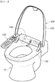
- FIG. 1 is a schematic perspective view of a toilet bowl and a bidet used for a toilet bowl according to an exemplary embodiment.
- a bidet 500 may be disposed on a toilet bowl 10, and may include a frame 100 and a drier 200.
- a nozzle assembly 110 may be disposed in an inside of the frame 100, in order to allow the toilet bowl 10 to move backwards and forwards.
- the nozzle assembly 110 may include a nozzle dispensing cleaning water to wash a user' s genitals or anus.
- the frame 100 may include a humidity sensor 150, a control unit 160, and a drier 200, disposed therein.
- the humidity sensor 150 may play a role in measuring humidity in the inside of the frame 100 and transmitting a measured humidity value to the control unit 160 as an electrical signal.
- the control unit 160 may detect a signal transmitted by the humidity sensor 150 and operate the drier 200. In this case, the control unit 160 may detect various signals input by a control panel 140, which will be subsequently described, and may be involved in an entirety of operation of the bidet 500.
- the drier 200 may be disposed in the inside of the frame 100, and may blow air onto the genitals and anus of a user and dry remaining moisture after washing. Therefore, the drier 200 may include a discharge port 221, from which air is discharged, disposed in a forward direction, in order to dry remaining moisture on a user's anus. The drier 200 will be subsequently described in detail.
- a toilet seat 120 may be hingedly coupled to the frame 100 so that the toilet seat 120 may revolve.
- a user may lower the toilet seat 120 onto the toilet bowl 10, or lift the toilet seat 120 above the toilet bowl 10, according to need.
- the toilet seat 120 may include a hose in which a heating wire is disposed or through which hot water flows, disposed therein, thus maintaining the toilet seat 120 at a specific temperature, not illustrated in a drawing.
- a cover 130 may be hingedly coupled to the frame 100 to be able to revolve, and the toilet bowl 10 may be opened or closed by allowing the cover 130 to revolve.
- the cover 130 may prevent a foreign substance from entering the toilet bowl, and may prevent an odor generated in the toilet bowl 10 from dissipating outwardly of the toilet bowl 10.
- a control panel 140 may be disposed on a side of the frame 100, in order to control the nozzle assembly 110 and the drier 200.
- the control panel 140 may include a plurality of buttons provided therein so that a user may select a predetermined function.
- a washing button (not illustrated) disposed in the control panel 140
- a washing water nozzle (not illustrated) may move in a forward direction of the toilet bowl 10 and spray cleaning water to the genitals and anus of a user.
- a drying button (not illustrated) after the genitals and anus are washed by cleaning water, air may be discharged from the discharge port 221 of the drier 200 and remove remaining moisture from the user's genitals.
- the frame 100 may include at least one air discharge hole 170 penetrating through the frame 100, disposed therein, and the inside of the frame 100 may be connected to an exterior thereof by the air discharge hole 170. In other words, ventilation of the inside of the frame 100 may be facilitated by the air discharge hole 170, and moisture in the inside of the frame 100 may be removed.
- At least one air discharge hole 170 may be disposed, and the air discharge hole 170 may be disposed on a bottom surface or on a rear surface of the frame 100.
- the bottom surface of the frame 100 may refer to a surface in which the frame 100 opposes the toilet bowl 10.
- the rear surface of the frame 100 may refer to a surface on which the toilet seat 120 is not disposed, among surfaces in contact with the bottom surface, illustrated in FIG. 1 .
- a position in which the air discharge hole 170 is disposed is not limited to a proposed example embodiment, but may vary as long as ventilation in the inside of the frame 100 is allowed.
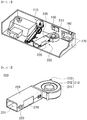
- FIG. 2 is a cutaway perspective view of a frame 100 according to an exemplary embodiment
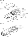
- FIG. 3 is a perspective view of a drier 200 according to an exemplary embodiment
- FIG. 4 is an exploded perspective view of a drier 200 illustrated in FIG. 3 .
- the drier 200 may be provided as a device disposed in the inside of the frame 100 and blowing air onto the genitals and anus of a user for drying thereof, and may include a blower 210, a drying duct 220, and a guide member 230.
- the blower 210 may be provided as a device generating air flow, and may include an air inlet 211 into which air flows.
- the air inlet 211 may be disposed on an upper surface of the blower 210, while air flows into the blower 210 through the air inlet 211 in such a manner that a blowing fan 212 disposed in the blower 210 is operated.
- the blowing fan 212 may be provided as a centrifugal fan discharging air, flowing in in an axial direction, in a radial direction, and may be operated by a fan motor.
- air flowing in through the air inlet 211 may be heated while the air passes through the heating device 222 disposed in the drying duct 220.
- heated air may move to the discharge port 221 or to the inside of the frame 100, according to a position of the guide member 230.
- a plurality of fixtures 213 may be disposed on an outer circumferential surface of the blower 210 so that the blower 210 may be fixed to the frame 100.
- the blower 210 in order for a fixture 213 to be disposed on a fixing boss (not illustrated) formed in the frame 100, the blower 210 may be mounted in the frame 100, and the fixture 213 may be coupled to the fixing boss by a screw.
- the drying duct 220 may be disposed on a side of the blower 210, and an air flow passage may be formed in a direction of the discharge port 221.
- the drying duct 220 may include a lower housing 223 having an open upper surface and an upper housing 224 having an open bottom surface.
- the lower housing 223 and the upper housing 224 may be connected by a connecting member, and may provide a passage through which air may move.
- an opening 225 corresponding to a form of the guide member 230 may be disposed in the drying duct 220, and the guide member 230 may be disposed to close the opening 225.
- the heating device 222 heating air discharged from the blower 210 may be disposed in the drying duct 220.
- any device that may give off heat and heat air may be provided as the heating device 222.
- the guide member 230 may be hingedly coupled to a side of the drying duct 220 to be able to revolve, and may form an exterior of the drying duct 220.
- the guide member 230 when the drier 200 is operated, the guide member 230 may be disposed on a side of the lower housing 223 or the upper housing 224 of the drying duct 220. In addition, the guide member 230 may be provided on at least one portion of side walls of the drying duct 220.
- the lower housing 223 and the upper housing 224 may include the opening 225 so that the guide member 230 may be provided therein.
- the opening 225 may be provided to have a form corresponding to the guide member 230, in order to be closed by the guide member 230.
- the guide member 230 may be hingedly coupled to a side of the opening 225 in a direction of the discharge port 221.
- the guide member 230 may be provided to have a flat panel shape. An end not hingedly coupled to the lower housing 223 and the upper housing 224 may be caught by a raised portion 226 disposed on the lower housing 223 and the upper housing 224.
- the guide member 230 may guide air flow generated by the blower 210 to the inside of the frame 100.
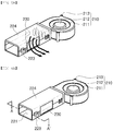
- FIG. 5A is a schematic view of air flow in the drying duct 220 before the guide member 230 is operated
- FIG. 5B is a schematic view of air flow in the drying duct 220 after the guide member 230 is operated.
- the humidity sensor 150 disposed in the inside of the frame 100 may transmit an electrical signal to the control unit 160, while the control unit 160 may transmit a driving signal to the drier 200, in response to the electrical signal.
- the guide member 230 may revolve inwardly of the drying duct 220, thus preventing air from flowing to the discharge port 221 and guiding air flow to the opening 225 (see FIG. 5B ), simultaneously.
- the guide member 230 may be provided in such a manner that the end not hingedly coupled thereto is in contact with an internal side surface of the drying duct 220, on which the guide member 230 is not disposed, thus closing the discharge port 221. Consequently, air flow generated by the blower 210 may move to the inside of the frame 100, and may dry the inside of the frame 100, thus decreasing humidity therein.
- the bidet may not include an additional drying device, but may use an existing drier 200 in order to dry the inside of the frame 100. Therefore, manufacturing costs may be reduced, and electronic components may be prevented from being corroded, thus extending a lifespan of a product. Furthermore, electrical current leakage may be prevented, thus guaranteeing the user's safety.
- FIG. 6 is a perspective view of a guide member 230 according to an exemplary embodiment in the present disclosure.
- a guide member according to an exemplary embodiment, may be provided in a manner the same as a guide member 230 described above, in terms of an entirety of a method of operating the guide member and a position thereof. However, only forms thereof may be different.
- the guide member 230 may be provided in such a manner that an external surface thereof is provided as a curved surface 231.
- the external surface may refer to a surface exposed outwardly before the guide member 230 is operated.
- the curved surface 231 may revolve inwardly of a drying duct 220, and air flow generated by a blower 210 may flow to an inside of a frame 100 along the curved surface 231. Therefore, a reduction in air speed may be minimized.
- FIG. 7 is a flowchart of a method for drying an inside of a bidet according to an exemplary embodiment in the present disclosure.
- measuring humidity in such a manner that a humidity sensor 150 disposed in an inside of a frame 100 measures a humidity value in the inside of the frame 100 may be performed in S10.
- any device that may measure a humidity value in the inside of the frame 100 may be used as the humidity sensor 150.
- transmitting a signal in such a manner that a signal is transmitted to a control unit 160 may be performed in S20, according to a humidity value measured by the humidity sensor 150, in more detail, in a case in which the humidity value that has been measured is higher than a predetermined humidity value.
- drying the inside of the frame 100 in such a manner that the control unit 160 that has received a signal from the humidity sensor 150 operates a drier 200 to remove moisture from the inside of the frame 100 may be performed in S30.
- the drier 200 may include a guide member 230 guiding air flow to the inside of the frame 100 by a signal received by the control unit 160.
- a composition and an operating process of a guide member may be provided in a manner the same as the guide member 230 according to exemplary embodiments described above.
Landscapes
- Health & Medical Sciences (AREA)
- Public Health (AREA)
- Epidemiology (AREA)
- Life Sciences & Earth Sciences (AREA)
- Engineering & Computer Science (AREA)
- Hydrology & Water Resources (AREA)
- Water Supply & Treatment (AREA)
- Molecular Biology (AREA)
- Bidet-Like Cleaning Device And Other Flush Toilet Accessories (AREA)
Abstract
Description
- The present disclosure relates to a bidet used to wash the genitals and anus, such as the pudendum, a periphery of the anus, and the like, after toilet use, and in more detail, to a bidet having an internal drying function.
- In general, bidets disposed on a toilet seat are devices dispensing cleaning water from a central region thereof, in order to wash the genitals and anus, such as the pudendum, the periphery of the anus, and the like, of a user. In recent times, the number of consumers using bidets in the home has increased.
- Bidets may have various functions, such as the adjustment of water pressure, water temperature, and the temperature of a toilet seat, and a drying function to dry moisture in such a manner that a warm current of air is dispensed after washing, as well as a washing function. In order to perform the functions described above, bidets may include a plurality of electronic components therein, such as a circuit board, an electronic device, and the like.
- Since toilet bowls have been commonly installed in bathrooms, along with washing facilities or shower facilities in the home, bidets installed on toilet bowls may be exposed to moisture, and moisture may occasionally penetrate into the inside of bidets.
- In a case in which moisture penetrates into the inside of a bidet, a plurality of electronic components disposed in a bidet may be vulnerable to corrosion or damage. In addition, users may be harmed due to a leakage current.
- Therefore, in order to extend a lifespan of a product and protect users, research into technologies for removing moisture in a case in which moisture penetrates into the inside of a bidet is urgently required.
- An aspect of the present disclosure may provide a bidet having an internal drying function for generating air flow in a bidet and removing moisture from the inside of the bidet and a method for drying an inside of the bidet.
- According to an aspect of the present disclosure, a bidet may include a drier disposed in an inside of a frame and blowing air. In addition, the drier may include a blower generating air flow, a drying duct connected to the blower and providing a passage through which air generated by the blower flows, and a guide member disposed on a side of the drying duct and guiding the air to a discharge port or the inside of the frame.
- In the bidet, the frame may include a humidity sensor disposed therein.
- In the bidet, the drying duct may include an opening corresponding to a form of the guide member, disposed therein, and the guide member may be disposed to close the opening.
- In the bidet, the guide member may be hingedly coupled to a side of the opening in a direction of the discharge port.
- In the bidet, the guide member may be disposed to close the discharge port when the drier is operated to guide air flow to the inside of the frame.
- In the bidet, an external surface of the guide member may be formed to be provided as a curved surface.
- In the bidet, the drying duct may include a heating device heating the air, disposed therein.
- In the bidet, the frame may include at least one air discharge hole penetrating through the frame, so that the inside of the frame may be connected to an exterior thereof.
- In the bidet, the frame may include a control unit transmitting a signal of the humidity sensor to the guide member, disposed therein.
- According to an aspect of the present disclosure, a method for drying an inside of a bidet may include measuring humidity in such a manner that a humidity sensor, disposed in an inside of the frame, measures humidity in the inside of the frame; transmitting a signal in such a manner that the humidity sensor transmits a signal to a control unit according to a humidity value; and drying the inside of the frame after the control unit receives the signal. In addition, the drying the inside of the frame may be performed by a drier disposed in the inside of the frame. The drier may include a guide member guiding air flow to the inside of the frame by the signal received from the control unit.
- According to an aspect of the present disclosure, a bidet may include a guide member guiding air flow, generated by a drier, to an inside of the bidet, so that ease in the removing of moisture from the inside of the bidet may be facilitated.
-
-
FIG. 1 is a schematic perspective view of a toilet bowl and a bidet used for a toilet bowl according to an exemplary embodiment in the present disclosure. -
FIG. 2 is a cutaway perspective view of a frame according to an exemplary embodiment in the present disclosure. -
FIG. 3 is a perspective view of a drier according to an exemplary embodiment in the present disclosure. -
FIG. 4 is an exploded perspective view of a drier illustrated inFIG. 3 . -
FIG. 5 is a schematic view of an operating guide member according to an exemplary embodiment in the present disclosure. -
FIG. 6A is a perspective view of a guide member combined with a drying duct according to a different exemplary embodiment in the present disclosure, whileFIG. 6B is a cross-sectional view of the guide member while operating, according to a different exemplary embodiment in the present disclosure. -
FIG. 7 is a flowchart of a method for drying an inside of a bidet according to an exemplary embodiment in the present disclosure. - The terminology used herein describes particular embodiments only, and the present inventive concept is not limited thereby. As used herein, the singular forms "a, " "an, " and "the" are intended to include the plural forms as well, unless the context clearly indicates otherwise. It will be further understood that the terms "comprises," and/or "comprising" when used in this specification, specify the presence of stated features, integers, steps, operations, members, elements, and/or groups thereof, but do not preclude the presence or addition of one or more other features, integers, steps, operations, members, elements, and/or groups thereof. The contents of the present inventive concept described below may have a variety of configurations and propose only a required configuration herein, but are not limited thereto.
- Hereinafter, exemplary embodiments of the present disclosure will be described in detail with reference to the accompanying drawings. The disclosure may, however, be exemplified in many different forms and should not be construed as being limited to the specific embodiments set forth herein, and those skilled in the art and understanding the present disclosure can easily accomplish retrogressive inventions or other embodiments included in the scope of the present disclosure by the addition, modification, and removal of components within the same scope, but those are construed as being included in the scope of the present disclosure. Like reference numerals will be used to designate like components having similar functions throughout the drawings within the scope of the present disclosure.
-
FIG. 1 is a schematic perspective view of a toilet bowl and a bidet used for a toilet bowl according to an exemplary embodiment. With reference toFIG. 1 , abidet 500, according to an exemplary embodiment, may be disposed on atoilet bowl 10, and may include aframe 100 and adrier 200. - A
nozzle assembly 110 may be disposed in an inside of theframe 100, in order to allow thetoilet bowl 10 to move backwards and forwards. In addition, thenozzle assembly 110 may include a nozzle dispensing cleaning water to wash a user' s genitals or anus. Furthermore, theframe 100 may include ahumidity sensor 150, acontrol unit 160, and adrier 200, disposed therein. Thehumidity sensor 150 may play a role in measuring humidity in the inside of theframe 100 and transmitting a measured humidity value to thecontrol unit 160 as an electrical signal. In addition, thecontrol unit 160 may detect a signal transmitted by thehumidity sensor 150 and operate thedrier 200. In this case, thecontrol unit 160 may detect various signals input by acontrol panel 140, which will be subsequently described, and may be involved in an entirety of operation of thebidet 500. - The
drier 200 may be disposed in the inside of theframe 100, and may blow air onto the genitals and anus of a user and dry remaining moisture after washing. Therefore, thedrier 200 may include adischarge port 221, from which air is discharged, disposed in a forward direction, in order to dry remaining moisture on a user's anus. Thedrier 200 will be subsequently described in detail. - In the meantime, a
toilet seat 120 may be hingedly coupled to theframe 100 so that thetoilet seat 120 may revolve. In addition, a user may lower thetoilet seat 120 onto thetoilet bowl 10, or lift thetoilet seat 120 above thetoilet bowl 10, according to need. - The
toilet seat 120 may include a hose in which a heating wire is disposed or through which hot water flows, disposed therein, thus maintaining thetoilet seat 120 at a specific temperature, not illustrated in a drawing. - A
cover 130 may be hingedly coupled to theframe 100 to be able to revolve, and thetoilet bowl 10 may be opened or closed by allowing thecover 130 to revolve. Thecover 130 may prevent a foreign substance from entering the toilet bowl, and may prevent an odor generated in thetoilet bowl 10 from dissipating outwardly of thetoilet bowl 10. - In addition, a
control panel 140 may be disposed on a side of theframe 100, in order to control thenozzle assembly 110 and thedrier 200. - The
control panel 140 may include a plurality of buttons provided therein so that a user may select a predetermined function. Hereinafter, a process of washing a user's genitals or anus will be briefly described. In a case in which the user pushes a washing button (not illustrated) disposed in thecontrol panel 140, a washing water nozzle (not illustrated) may move in a forward direction of thetoilet bowl 10 and spray cleaning water to the genitals and anus of a user. In a case in which the user pushes a drying button (not illustrated) after the genitals and anus are washed by cleaning water, air may be discharged from thedischarge port 221 of the drier 200 and remove remaining moisture from the user's genitals. - In addition, the
frame 100 may include at least oneair discharge hole 170 penetrating through theframe 100, disposed therein, and the inside of theframe 100 may be connected to an exterior thereof by theair discharge hole 170. In other words, ventilation of the inside of theframe 100 may be facilitated by theair discharge hole 170, and moisture in the inside of theframe 100 may be removed. - At least one
air discharge hole 170 may be disposed, and theair discharge hole 170 may be disposed on a bottom surface or on a rear surface of theframe 100. - In this case, the bottom surface of the
frame 100 may refer to a surface in which theframe 100 opposes thetoilet bowl 10. In addition, the rear surface of theframe 100 may refer to a surface on which thetoilet seat 120 is not disposed, among surfaces in contact with the bottom surface, illustrated inFIG. 1 . - However, a position in which the
air discharge hole 170 is disposed is not limited to a proposed example embodiment, but may vary as long as ventilation in the inside of theframe 100 is allowed. -
FIG. 2 is a cutaway perspective view of aframe 100 according to an exemplary embodiment,FIG. 3 is a perspective view of a drier 200 according to an exemplary embodiment, andFIG. 4 is an exploded perspective view of a drier 200 illustrated inFIG. 3 . - With reference to
FIGS. 2 to 4 , the drier 200, according to an exemplary embodiment, may be provided as a device disposed in the inside of theframe 100 and blowing air onto the genitals and anus of a user for drying thereof, and may include ablower 210, a dryingduct 220, and aguide member 230. - The
blower 210 may be provided as a device generating air flow, and may include anair inlet 211 into which air flows. Theair inlet 211 may be disposed on an upper surface of theblower 210, while air flows into theblower 210 through theair inlet 211 in such a manner that a blowingfan 212 disposed in theblower 210 is operated. - In this case, the blowing
fan 212 may be provided as a centrifugal fan discharging air, flowing in in an axial direction, in a radial direction, and may be operated by a fan motor. - Subsequently, air flowing in through the
air inlet 211 may be heated while the air passes through theheating device 222 disposed in the dryingduct 220. In addition, heated air may move to thedischarge port 221 or to the inside of theframe 100, according to a position of theguide member 230. - In the meantime, a plurality of
fixtures 213 may be disposed on an outer circumferential surface of theblower 210 so that theblower 210 may be fixed to theframe 100. In other words, in order for afixture 213 to be disposed on a fixing boss (not illustrated) formed in theframe 100, theblower 210 may be mounted in theframe 100, and thefixture 213 may be coupled to the fixing boss by a screw. - The drying
duct 220 may be disposed on a side of theblower 210, and an air flow passage may be formed in a direction of thedischarge port 221. In other words, the dryingduct 220 may include alower housing 223 having an open upper surface and anupper housing 224 having an open bottom surface. In addition, thelower housing 223 and theupper housing 224 may be connected by a connecting member, and may provide a passage through which air may move. - In addition, an
opening 225 corresponding to a form of theguide member 230, which will subsequently be described, may be disposed in the dryingduct 220, and theguide member 230 may be disposed to close theopening 225. - Furthermore, the
heating device 222 heating air discharged from theblower 210 may be disposed in the dryingduct 220. In this case, any device that may give off heat and heat air may be provided as theheating device 222. - The
guide member 230 may be hingedly coupled to a side of the dryingduct 220 to be able to revolve, and may form an exterior of the dryingduct 220. - In other words, when the drier 200 is operated, the
guide member 230 may be disposed on a side of thelower housing 223 or theupper housing 224 of the dryingduct 220. In addition, theguide member 230 may be provided on at least one portion of side walls of the dryingduct 220. - The
lower housing 223 and theupper housing 224 may include theopening 225 so that theguide member 230 may be provided therein. In this case, theopening 225 may be provided to have a form corresponding to theguide member 230, in order to be closed by theguide member 230. In addition, theguide member 230 may be hingedly coupled to a side of theopening 225 in a direction of thedischarge port 221. - In addition, the
guide member 230 may be provided to have a flat panel shape. An end not hingedly coupled to thelower housing 223 and theupper housing 224 may be caught by a raisedportion 226 disposed on thelower housing 223 and theupper housing 224. - The
guide member 230 may guide air flow generated by theblower 210 to the inside of theframe 100. -
FIG. 5A is a schematic view of air flow in the dryingduct 220 before theguide member 230 is operated, whileFIG. 5B is a schematic view of air flow in the dryingduct 220 after theguide member 230 is operated. - With reference to
FIG. 5 , a process of guiding air flow to the inside of theframe 100 in such a manner that theguide member 230 is operated will be described in detail. In a case in which humidity in the inside of theframe 100 is increased to a predetermined humidity value or higher, thehumidity sensor 150 disposed in the inside of theframe 100 may transmit an electrical signal to thecontrol unit 160, while thecontrol unit 160 may transmit a driving signal to the drier 200, in response to the electrical signal. - In this case, the
guide member 230 may revolve inwardly of the dryingduct 220, thus preventing air from flowing to thedischarge port 221 and guiding air flow to the opening 225 (seeFIG. 5B ), simultaneously. In other words, theguide member 230 may be provided in such a manner that the end not hingedly coupled thereto is in contact with an internal side surface of the dryingduct 220, on which theguide member 230 is not disposed, thus closing thedischarge port 221. Consequently, air flow generated by theblower 210 may move to the inside of theframe 100, and may dry the inside of theframe 100, thus decreasing humidity therein. - In other words, the bidet, according to an exemplary embodiment, may not include an additional drying device, but may use an existing drier 200 in order to dry the inside of the
frame 100. Therefore, manufacturing costs may be reduced, and electronic components may be prevented from being corroded, thus extending a lifespan of a product. Furthermore, electrical current leakage may be prevented, thus guaranteeing the user's safety. -
FIG. 6 is a perspective view of aguide member 230 according to an exemplary embodiment in the present disclosure. With reference toFIG. 6 , a guide member, according to an exemplary embodiment, may be provided in a manner the same as aguide member 230 described above, in terms of an entirety of a method of operating the guide member and a position thereof. However, only forms thereof may be different. - Therefore, a detailed description of the same component may be omitted, and only a description provided above may be included.
- With reference to
FIG. 6 , theguide member 230, according to an exemplary embodiment, may be provided in such a manner that an external surface thereof is provided as acurved surface 231. In this case, the external surface may refer to a surface exposed outwardly before theguide member 230 is operated. - In other words, in a case in which the
guide member 230 is operated, thecurved surface 231 may revolve inwardly of a dryingduct 220, and air flow generated by ablower 210 may flow to an inside of aframe 100 along thecurved surface 231. Therefore, a reduction in air speed may be minimized. -
FIG. 7 is a flowchart of a method for drying an inside of a bidet according to an exemplary embodiment in the present disclosure. - With reference to
FIG. 7 , a method for drying an inside of a bidet, according to a different exemplary embodiment in the present disclosure, will be described. First, measuring humidity in such a manner that ahumidity sensor 150 disposed in an inside of aframe 100 measures a humidity value in the inside of theframe 100 may be performed in S10. - In the meantime, it is determined that any device that may measure a humidity value in the inside of the
frame 100 may be used as thehumidity sensor 150. - Subsequently, after measuring humidity is performed in S10, transmitting a signal in such a manner that a signal is transmitted to a
control unit 160 may be performed in S20, according to a humidity value measured by thehumidity sensor 150, in more detail, in a case in which the humidity value that has been measured is higher than a predetermined humidity value. - Subsequently, drying the inside of the
frame 100 in such a manner that thecontrol unit 160 that has received a signal from thehumidity sensor 150 operates a drier 200 to remove moisture from the inside of theframe 100 may be performed in S30. - In this case, the drier 200 may include a
guide member 230 guiding air flow to the inside of theframe 100 by a signal received by thecontrol unit 160. In addition, a composition and an operating process of a guide member may be provided in a manner the same as theguide member 230 according to exemplary embodiments described above. - While exemplary embodiments have been shown and described above, it will be apparent to those skilled in the art that modifications and variations could be made without departing from the scope of the present invention as defined by the appended claims.
Claims (10)
- A bidet, comprising:a drier disposed in an inside of a frame and blowing air,wherein the drier includes a blower generating air flow;a drying duct connected to the blower and providing a passage through which air generated by the blower flows; anda guide member disposed on a side of the drying duct and guiding the air to a discharge port or the inside of the frame.
- The bidet of claim 1, wherein the frame comprises a humidity sensor disposed in the inside of the frame.
- The bidet of claim 1, wherein the drying duct comprises an opening corresponding to a form of the guide member, disposed in the drying duct, and the guide member may be disposed to close the opening.
- The bidet of claim 3, wherein the guide member is hingedly coupled to a side of the opening in a direction of the discharge port.
- The bidet of claim 1, wherein the guide member is disposed to close the discharge port when the drier is operated to guide air flow to the inside of the frame.
- The bidet of claim 1, wherein an external surface of the guide member is formed to be provided as a curved surface.
- The bidet of claim 1, wherein the drying duct comprises a heating device heating the air, disposed in the drying duct.
- The bidet of claim 1, wherein the frame comprises at least one air discharge hole penetrating through the frame, connecting the inside and an exterior of the frame.
- The bidet of claim 1, wherein the frame comprises a control unit transmitting a signal of the humidity sensor to the guide member, disposed in the inside of the frame.
- A method for drying an inside of a bidet, comprising:a step of measuring humidity, in which a humidity sensor, disposed in an inside of a frame, measures a humidity value in the inside of the frame;a step of transmitting a signal, in which the humidity sensor transmits a signal to a control unit according to the humidity value; anda step of drying, in which the control unit receives the signal, and a drier dries the inside of the frame,wherein the step of drying is performed by the drier disposed in the inside of the frame, and the drier includes a guide member guiding air flow to the inside of the frame by the signal received from the control unit.
Applications Claiming Priority (2)
| Application Number | Priority Date | Filing Date | Title |
|---|---|---|---|
| KR1020140074813A KR20150145762A (en) | 2014-06-19 | 2014-06-19 | Bidet with drying function and Method for drying the inside |
| PCT/KR2015/006049 WO2015194819A1 (en) | 2014-06-19 | 2015-06-16 | Bidet having internal drying function and method for drying inside of bidet |
Publications (3)
| Publication Number | Publication Date |
|---|---|
| EP3159458A1 true EP3159458A1 (en) | 2017-04-26 |
| EP3159458A4 EP3159458A4 (en) | 2017-07-26 |
| EP3159458B1 EP3159458B1 (en) | 2021-08-04 |
Family
ID=54935749
Family Applications (1)
| Application Number | Title | Priority Date | Filing Date |
|---|---|---|---|
| EP15809339.3A Active EP3159458B1 (en) | 2014-06-19 | 2015-06-16 | Bidet having internal drying function and method for drying inside of bidet |
Country Status (4)
| Country | Link |
|---|---|
| EP (1) | EP3159458B1 (en) |
| KR (1) | KR20150145762A (en) |
| CN (1) | CN106460378A (en) |
| WO (1) | WO2015194819A1 (en) |
Cited By (1)
| Publication number | Priority date | Publication date | Assignee | Title |
|---|---|---|---|---|
| EP3339520A1 (en) * | 2016-12-21 | 2018-06-27 | Geberit International AG | Wc bidet device with air supply device |
Families Citing this family (2)
| Publication number | Priority date | Publication date | Assignee | Title |
|---|---|---|---|---|
| CN110841179A (en) * | 2019-12-25 | 2020-02-28 | 余丽红 | Lower body medicine feeding device for gynecology department with good medicine applying effect |
| CN118997286A (en) * | 2024-09-27 | 2024-11-22 | 九牧厨卫股份有限公司 | Toilet and air treatment device |
Family Cites Families (11)
| Publication number | Priority date | Publication date | Assignee | Title |
|---|---|---|---|---|
| KR0132759Y1 (en) * | 1996-03-22 | 1998-12-15 | 이세용 | Internal drying unit of hot water cleaner |
| KR100494575B1 (en) * | 2003-03-10 | 2005-06-10 | 엘지전자 주식회사 | Drying apparatus and method using humidity sensor |
| CN1570299A (en) * | 2003-07-18 | 2005-01-26 | 倪永志 | Toilet automatic ventilation and flushing integrated control system |
| US7726599B2 (en) * | 2003-12-31 | 2010-06-01 | Kimberly-Clark Worldwide, Inc. | Apparatus and method for dispensing sheet material |
| KR200349284Y1 (en) * | 2004-02-11 | 2004-05-04 | 주식회사 성신테크 | Ventilator of bidet |
| JP2007162333A (en) * | 2005-12-14 | 2007-06-28 | Aisin Seiki Co Ltd | Toilet seat device |
| KR101576826B1 (en) * | 2009-06-01 | 2015-12-14 | 코웨이 주식회사 | Bidet apparatus |
| KR101181550B1 (en) * | 2010-02-05 | 2012-09-10 | 이영국 | Bidet with intellectual power-saving function |
| KR20120002300A (en) * | 2010-06-30 | 2012-01-05 | 웅진코웨이주식회사 | Bidet with Sterilization Dryer |
| CN103405044A (en) * | 2013-08-21 | 2013-11-27 | 戴桂芬 | Intelligent shoe cabinet |
| CN103767355A (en) * | 2014-01-24 | 2014-05-07 | 南通钰成光电科技有限公司 | Shoe cabinet |
-
2014
- 2014-06-19 KR KR1020140074813A patent/KR20150145762A/en not_active Ceased
-
2015
- 2015-06-16 EP EP15809339.3A patent/EP3159458B1/en active Active
- 2015-06-16 WO PCT/KR2015/006049 patent/WO2015194819A1/en not_active Ceased
- 2015-06-16 CN CN201580032933.1A patent/CN106460378A/en active Pending
Cited By (1)
| Publication number | Priority date | Publication date | Assignee | Title |
|---|---|---|---|---|
| EP3339520A1 (en) * | 2016-12-21 | 2018-06-27 | Geberit International AG | Wc bidet device with air supply device |
Also Published As
| Publication number | Publication date |
|---|---|
| WO2015194819A1 (en) | 2015-12-23 |
| EP3159458A4 (en) | 2017-07-26 |
| CN106460378A (en) | 2017-02-22 |
| EP3159458B1 (en) | 2021-08-04 |
| KR20150145762A (en) | 2015-12-31 |
Similar Documents
| Publication | Publication Date | Title |
|---|---|---|
| US10100504B2 (en) | Bidet apparatus | |
| KR100786217B1 (en) | Hot water washer and its cleaning method | |
| EP3159458B1 (en) | Bidet having internal drying function and method for drying inside of bidet | |
| KR101977034B1 (en) | Bidet with drying function | |
| KR920003844B1 (en) | Sanitary Equipments for Clean Room | |
| KR101576826B1 (en) | Bidet apparatus | |
| KR101504642B1 (en) | Bidet for include a hot water feature and its control method thereof | |
| JP6274593B1 (en) | Sanitary washing device | |
| JP5881561B2 (en) | Hand dryer with integrated wash-basin | |
| JP6677933B2 (en) | Sanitary washing equipment | |
| KR20160049623A (en) | Drying apparatus for bidet and bidet having the same | |
| KR20090130591A (en) | Toilet seat bidet | |
| JP2003275112A (en) | Hand washing unit with drying function | |
| KR20160066117A (en) | Faucet with having a hand dryer | |
| KR102426305B1 (en) | Bidet frame and bidet including the same | |
| CN112105786B (en) | Drying device with rotary drying nozzle and intelligent toilet lid device using same | |
| KR102180145B1 (en) | Electronic Bidet Having Dry Function | |
| JP5593723B2 (en) | Toilet bowl cleaning device | |
| JP2017172272A (en) | Toilet device | |
| KR102419984B1 (en) | method for controlling a bidet having a deodorization apparatus | |
| JP2019167790A (en) | Toilet seat device | |
| KR20100102826A (en) | Bidet apparatus | |
| JP4816190B2 (en) | Toilet equipment | |
| JP4916325B2 (en) | Dishwasher | |
| JP6726894B2 (en) | Toilet device |
Legal Events
| Date | Code | Title | Description |
|---|---|---|---|
| STAA | Information on the status of an ep patent application or granted ep patent |
Free format text: STATUS: THE INTERNATIONAL PUBLICATION HAS BEEN MADE |
|
| PUAI | Public reference made under article 153(3) epc to a published international application that has entered the european phase |
Free format text: ORIGINAL CODE: 0009012 |
|
| STAA | Information on the status of an ep patent application or granted ep patent |
Free format text: STATUS: REQUEST FOR EXAMINATION WAS MADE |
|
| 17P | Request for examination filed |
Effective date: 20161221 |
|
| AK | Designated contracting states |
Kind code of ref document: A1 Designated state(s): AL AT BE BG CH CY CZ DE DK EE ES FI FR GB GR HR HU IE IS IT LI LT LU LV MC MK MT NL NO PL PT RO RS SE SI SK SM TR |
|
| AX | Request for extension of the european patent |
Extension state: BA ME |
|
| A4 | Supplementary search report drawn up and despatched |
Effective date: 20170627 |
|
| RIC1 | Information provided on ipc code assigned before grant |
Ipc: E03D 9/08 20060101AFI20170621BHEP Ipc: E03D 9/052 20060101ALI20170621BHEP |
|
| DAV | Request for validation of the european patent (deleted) | ||
| DAX | Request for extension of the european patent (deleted) | ||
| STAA | Information on the status of an ep patent application or granted ep patent |
Free format text: STATUS: EXAMINATION IS IN PROGRESS |
|
| 17Q | First examination report despatched |
Effective date: 20191004 |
|
| GRAP | Despatch of communication of intention to grant a patent |
Free format text: ORIGINAL CODE: EPIDOSNIGR1 |
|
| STAA | Information on the status of an ep patent application or granted ep patent |
Free format text: STATUS: GRANT OF PATENT IS INTENDED |
|
| INTG | Intention to grant announced |
Effective date: 20210215 |
|
| GRAS | Grant fee paid |
Free format text: ORIGINAL CODE: EPIDOSNIGR3 |
|
| GRAA | (expected) grant |
Free format text: ORIGINAL CODE: 0009210 |
|
| STAA | Information on the status of an ep patent application or granted ep patent |
Free format text: STATUS: THE PATENT HAS BEEN GRANTED |
|
| AK | Designated contracting states |
Kind code of ref document: B1 Designated state(s): AL AT BE BG CH CY CZ DE DK EE ES FI FR GB GR HR HU IE IS IT LI LT LU LV MC MK MT NL NO PL PT RO RS SE SI SK SM TR |
|
| REG | Reference to a national code |
Ref country code: GB Ref legal event code: FG4D |
|
| REG | Reference to a national code |
Ref country code: AT Ref legal event code: REF Ref document number: 1417127 Country of ref document: AT Kind code of ref document: T Effective date: 20210815 |
|
| REG | Reference to a national code |
Ref country code: CH Ref legal event code: EP |
|
| REG | Reference to a national code |
Ref country code: DE Ref legal event code: R096 Ref document number: 602015071992 Country of ref document: DE |
|
| REG | Reference to a national code |
Ref country code: IE Ref legal event code: FG4D |
|
| REG | Reference to a national code |
Ref country code: LT Ref legal event code: MG9D |
|
| REG | Reference to a national code |
Ref country code: NL Ref legal event code: MP Effective date: 20210804 |
|
| REG | Reference to a national code |
Ref country code: AT Ref legal event code: MK05 Ref document number: 1417127 Country of ref document: AT Kind code of ref document: T Effective date: 20210804 |
|
| PG25 | Lapsed in a contracting state [announced via postgrant information from national office to epo] |
Ref country code: HR Free format text: LAPSE BECAUSE OF FAILURE TO SUBMIT A TRANSLATION OF THE DESCRIPTION OR TO PAY THE FEE WITHIN THE PRESCRIBED TIME-LIMIT Effective date: 20210804 Ref country code: RS Free format text: LAPSE BECAUSE OF FAILURE TO SUBMIT A TRANSLATION OF THE DESCRIPTION OR TO PAY THE FEE WITHIN THE PRESCRIBED TIME-LIMIT Effective date: 20210804 Ref country code: SE Free format text: LAPSE BECAUSE OF FAILURE TO SUBMIT A TRANSLATION OF THE DESCRIPTION OR TO PAY THE FEE WITHIN THE PRESCRIBED TIME-LIMIT Effective date: 20210804 Ref country code: FI Free format text: LAPSE BECAUSE OF FAILURE TO SUBMIT A TRANSLATION OF THE DESCRIPTION OR TO PAY THE FEE WITHIN THE PRESCRIBED TIME-LIMIT Effective date: 20210804 Ref country code: ES Free format text: LAPSE BECAUSE OF FAILURE TO SUBMIT A TRANSLATION OF THE DESCRIPTION OR TO PAY THE FEE WITHIN THE PRESCRIBED TIME-LIMIT Effective date: 20210804 Ref country code: PT Free format text: LAPSE BECAUSE OF FAILURE TO SUBMIT A TRANSLATION OF THE DESCRIPTION OR TO PAY THE FEE WITHIN THE PRESCRIBED TIME-LIMIT Effective date: 20211206 Ref country code: NO Free format text: LAPSE BECAUSE OF FAILURE TO SUBMIT A TRANSLATION OF THE DESCRIPTION OR TO PAY THE FEE WITHIN THE PRESCRIBED TIME-LIMIT Effective date: 20211104 Ref country code: LT Free format text: LAPSE BECAUSE OF FAILURE TO SUBMIT A TRANSLATION OF THE DESCRIPTION OR TO PAY THE FEE WITHIN THE PRESCRIBED TIME-LIMIT Effective date: 20210804 Ref country code: AT Free format text: LAPSE BECAUSE OF FAILURE TO SUBMIT A TRANSLATION OF THE DESCRIPTION OR TO PAY THE FEE WITHIN THE PRESCRIBED TIME-LIMIT Effective date: 20210804 Ref country code: BG Free format text: LAPSE BECAUSE OF FAILURE TO SUBMIT A TRANSLATION OF THE DESCRIPTION OR TO PAY THE FEE WITHIN THE PRESCRIBED TIME-LIMIT Effective date: 20211104 |
|
| PG25 | Lapsed in a contracting state [announced via postgrant information from national office to epo] |
Ref country code: PL Free format text: LAPSE BECAUSE OF FAILURE TO SUBMIT A TRANSLATION OF THE DESCRIPTION OR TO PAY THE FEE WITHIN THE PRESCRIBED TIME-LIMIT Effective date: 20210804 Ref country code: LV Free format text: LAPSE BECAUSE OF FAILURE TO SUBMIT A TRANSLATION OF THE DESCRIPTION OR TO PAY THE FEE WITHIN THE PRESCRIBED TIME-LIMIT Effective date: 20210804 Ref country code: GR Free format text: LAPSE BECAUSE OF FAILURE TO SUBMIT A TRANSLATION OF THE DESCRIPTION OR TO PAY THE FEE WITHIN THE PRESCRIBED TIME-LIMIT Effective date: 20211105 |
|
| PG25 | Lapsed in a contracting state [announced via postgrant information from national office to epo] |
Ref country code: NL Free format text: LAPSE BECAUSE OF FAILURE TO SUBMIT A TRANSLATION OF THE DESCRIPTION OR TO PAY THE FEE WITHIN THE PRESCRIBED TIME-LIMIT Effective date: 20210804 |
|
| PG25 | Lapsed in a contracting state [announced via postgrant information from national office to epo] |
Ref country code: DK Free format text: LAPSE BECAUSE OF FAILURE TO SUBMIT A TRANSLATION OF THE DESCRIPTION OR TO PAY THE FEE WITHIN THE PRESCRIBED TIME-LIMIT Effective date: 20210804 |
|
| REG | Reference to a national code |
Ref country code: DE Ref legal event code: R097 Ref document number: 602015071992 Country of ref document: DE |
|
| PG25 | Lapsed in a contracting state [announced via postgrant information from national office to epo] |
Ref country code: SM Free format text: LAPSE BECAUSE OF FAILURE TO SUBMIT A TRANSLATION OF THE DESCRIPTION OR TO PAY THE FEE WITHIN THE PRESCRIBED TIME-LIMIT Effective date: 20210804 Ref country code: SK Free format text: LAPSE BECAUSE OF FAILURE TO SUBMIT A TRANSLATION OF THE DESCRIPTION OR TO PAY THE FEE WITHIN THE PRESCRIBED TIME-LIMIT Effective date: 20210804 Ref country code: RO Free format text: LAPSE BECAUSE OF FAILURE TO SUBMIT A TRANSLATION OF THE DESCRIPTION OR TO PAY THE FEE WITHIN THE PRESCRIBED TIME-LIMIT Effective date: 20210804 Ref country code: EE Free format text: LAPSE BECAUSE OF FAILURE TO SUBMIT A TRANSLATION OF THE DESCRIPTION OR TO PAY THE FEE WITHIN THE PRESCRIBED TIME-LIMIT Effective date: 20210804 Ref country code: CZ Free format text: LAPSE BECAUSE OF FAILURE TO SUBMIT A TRANSLATION OF THE DESCRIPTION OR TO PAY THE FEE WITHIN THE PRESCRIBED TIME-LIMIT Effective date: 20210804 Ref country code: AL Free format text: LAPSE BECAUSE OF FAILURE TO SUBMIT A TRANSLATION OF THE DESCRIPTION OR TO PAY THE FEE WITHIN THE PRESCRIBED TIME-LIMIT Effective date: 20210804 |
|
| PLBE | No opposition filed within time limit |
Free format text: ORIGINAL CODE: 0009261 |
|
| STAA | Information on the status of an ep patent application or granted ep patent |
Free format text: STATUS: NO OPPOSITION FILED WITHIN TIME LIMIT |
|
| 26N | No opposition filed |
Effective date: 20220506 |
|
| PG25 | Lapsed in a contracting state [announced via postgrant information from national office to epo] |
Ref country code: IT Free format text: LAPSE BECAUSE OF FAILURE TO SUBMIT A TRANSLATION OF THE DESCRIPTION OR TO PAY THE FEE WITHIN THE PRESCRIBED TIME-LIMIT Effective date: 20210804 |
|
| PG25 | Lapsed in a contracting state [announced via postgrant information from national office to epo] |
Ref country code: SI Free format text: LAPSE BECAUSE OF FAILURE TO SUBMIT A TRANSLATION OF THE DESCRIPTION OR TO PAY THE FEE WITHIN THE PRESCRIBED TIME-LIMIT Effective date: 20210804 |
|
| PG25 | Lapsed in a contracting state [announced via postgrant information from national office to epo] |
Ref country code: MC Free format text: LAPSE BECAUSE OF FAILURE TO SUBMIT A TRANSLATION OF THE DESCRIPTION OR TO PAY THE FEE WITHIN THE PRESCRIBED TIME-LIMIT Effective date: 20210804 |
|
| REG | Reference to a national code |
Ref country code: CH Ref legal event code: PL |
|
| REG | Reference to a national code |
Ref country code: BE Ref legal event code: MM Effective date: 20220630 |
|
| GBPC | Gb: european patent ceased through non-payment of renewal fee |
Effective date: 20220616 |
|
| PG25 | Lapsed in a contracting state [announced via postgrant information from national office to epo] |
Ref country code: LU Free format text: LAPSE BECAUSE OF NON-PAYMENT OF DUE FEES Effective date: 20220616 Ref country code: LI Free format text: LAPSE BECAUSE OF NON-PAYMENT OF DUE FEES Effective date: 20220630 Ref country code: IE Free format text: LAPSE BECAUSE OF NON-PAYMENT OF DUE FEES Effective date: 20220616 Ref country code: FR Free format text: LAPSE BECAUSE OF NON-PAYMENT OF DUE FEES Effective date: 20220630 Ref country code: CH Free format text: LAPSE BECAUSE OF NON-PAYMENT OF DUE FEES Effective date: 20220630 |
|
| PG25 | Lapsed in a contracting state [announced via postgrant information from national office to epo] |
Ref country code: GB Free format text: LAPSE BECAUSE OF NON-PAYMENT OF DUE FEES Effective date: 20220616 Ref country code: BE Free format text: LAPSE BECAUSE OF NON-PAYMENT OF DUE FEES Effective date: 20220630 |
|
| PG25 | Lapsed in a contracting state [announced via postgrant information from national office to epo] |
Ref country code: HU Free format text: LAPSE BECAUSE OF FAILURE TO SUBMIT A TRANSLATION OF THE DESCRIPTION OR TO PAY THE FEE WITHIN THE PRESCRIBED TIME-LIMIT; INVALID AB INITIO Effective date: 20150616 |
|
| PG25 | Lapsed in a contracting state [announced via postgrant information from national office to epo] |
Ref country code: MK Free format text: LAPSE BECAUSE OF FAILURE TO SUBMIT A TRANSLATION OF THE DESCRIPTION OR TO PAY THE FEE WITHIN THE PRESCRIBED TIME-LIMIT Effective date: 20210804 Ref country code: CY Free format text: LAPSE BECAUSE OF FAILURE TO SUBMIT A TRANSLATION OF THE DESCRIPTION OR TO PAY THE FEE WITHIN THE PRESCRIBED TIME-LIMIT Effective date: 20210804 |
|
| PG25 | Lapsed in a contracting state [announced via postgrant information from national office to epo] |
Ref country code: MT Free format text: LAPSE BECAUSE OF FAILURE TO SUBMIT A TRANSLATION OF THE DESCRIPTION OR TO PAY THE FEE WITHIN THE PRESCRIBED TIME-LIMIT Effective date: 20210804 |
|
| PGFP | Annual fee paid to national office [announced via postgrant information from national office to epo] |
Ref country code: DE Payment date: 20250320 Year of fee payment: 11 |
|
| PG25 | Lapsed in a contracting state [announced via postgrant information from national office to epo] |
Ref country code: TR Free format text: LAPSE BECAUSE OF FAILURE TO SUBMIT A TRANSLATION OF THE DESCRIPTION OR TO PAY THE FEE WITHIN THE PRESCRIBED TIME-LIMIT Effective date: 20210804 |