EP3159427A1 - Valve for internal combustion engines - Google Patents
Valve for internal combustion engines Download PDFInfo
- Publication number
- EP3159427A1 EP3159427A1 EP16192608.4A EP16192608A EP3159427A1 EP 3159427 A1 EP3159427 A1 EP 3159427A1 EP 16192608 A EP16192608 A EP 16192608A EP 3159427 A1 EP3159427 A1 EP 3159427A1
- Authority
- EP
- European Patent Office
- Prior art keywords
- valve
- nitrided layer
- nitrogen
- corrosion
- valves
- Prior art date
- Legal status (The legal status is an assumption and is not a legal conclusion. Google has not performed a legal analysis and makes no representation as to the accuracy of the status listed.)
- Withdrawn
Links
- 238000002485 combustion reaction Methods 0.000 title claims abstract description 15
- IJGRMHOSHXDMSA-UHFFFAOYSA-N Atomic nitrogen Chemical compound N#N IJGRMHOSHXDMSA-UHFFFAOYSA-N 0.000 claims abstract description 52
- 229910052757 nitrogen Inorganic materials 0.000 claims abstract description 26
- 239000011159 matrix material Substances 0.000 claims abstract description 14
- 239000006104 solid solution Substances 0.000 claims abstract description 14
- 239000000758 substrate Substances 0.000 claims abstract description 13
- 229910052804 chromium Inorganic materials 0.000 claims description 9
- 239000011651 chromium Substances 0.000 claims description 9
- VYZAMTAEIAYCRO-UHFFFAOYSA-N Chromium Chemical compound [Cr] VYZAMTAEIAYCRO-UHFFFAOYSA-N 0.000 claims description 7
- CWYNVVGOOAEACU-UHFFFAOYSA-N Fe2+ Chemical compound [Fe+2] CWYNVVGOOAEACU-UHFFFAOYSA-N 0.000 claims description 4
- 230000003247 decreasing effect Effects 0.000 claims description 4
- 230000007704 transition Effects 0.000 claims description 4
- 230000007797 corrosion Effects 0.000 abstract description 51
- 238000005260 corrosion Methods 0.000 abstract description 51
- 238000009792 diffusion process Methods 0.000 abstract description 10
- 238000010438 heat treatment Methods 0.000 abstract description 9
- 238000000034 method Methods 0.000 description 15
- 230000008569 process Effects 0.000 description 12
- 239000000463 material Substances 0.000 description 9
- 229910001220 stainless steel Inorganic materials 0.000 description 9
- 230000035882 stress Effects 0.000 description 8
- 239000007789 gas Substances 0.000 description 7
- 229910000831 Steel Inorganic materials 0.000 description 5
- 150000004767 nitrides Chemical class 0.000 description 5
- 239000010959 steel Substances 0.000 description 5
- 230000015572 biosynthetic process Effects 0.000 description 4
- 229910000734 martensite Inorganic materials 0.000 description 4
- 238000004519 manufacturing process Methods 0.000 description 3
- 239000000243 solution Substances 0.000 description 3
- 239000010935 stainless steel Substances 0.000 description 3
- 239000000126 substance Substances 0.000 description 3
- 230000008901 benefit Effects 0.000 description 2
- -1 chromium nitrides Chemical class 0.000 description 2
- 229910052751 metal Inorganic materials 0.000 description 2
- 239000002184 metal Substances 0.000 description 2
- 150000001247 metal acetylides Chemical class 0.000 description 2
- 230000004048 modification Effects 0.000 description 2
- 238000012986 modification Methods 0.000 description 2
- 238000001556 precipitation Methods 0.000 description 2
- 238000009877 rendering Methods 0.000 description 2
- 238000007789 sealing Methods 0.000 description 2
- QGZKDVFQNNGYKY-UHFFFAOYSA-N Ammonia Chemical compound N QGZKDVFQNNGYKY-UHFFFAOYSA-N 0.000 description 1
- RYGMFSIKBFXOCR-UHFFFAOYSA-N Copper Chemical compound [Cu] RYGMFSIKBFXOCR-UHFFFAOYSA-N 0.000 description 1
- QAOWNCQODCNURD-UHFFFAOYSA-N Sulfuric acid Chemical compound OS(O)(=O)=O QAOWNCQODCNURD-UHFFFAOYSA-N 0.000 description 1
- WGLPBDUCMAPZCE-UHFFFAOYSA-N Trioxochromium Chemical compound O=[Cr](=O)=O WGLPBDUCMAPZCE-UHFFFAOYSA-N 0.000 description 1
- 230000002378 acidificating effect Effects 0.000 description 1
- 230000001464 adherent effect Effects 0.000 description 1
- 229910045601 alloy Inorganic materials 0.000 description 1
- 239000000956 alloy Substances 0.000 description 1
- 238000006243 chemical reaction Methods 0.000 description 1
- 229910000423 chromium oxide Inorganic materials 0.000 description 1
- 239000011248 coating agent Substances 0.000 description 1
- 238000000576 coating method Methods 0.000 description 1
- 230000006835 compression Effects 0.000 description 1
- 238000007906 compression Methods 0.000 description 1
- 229910052802 copper Inorganic materials 0.000 description 1
- 239000010949 copper Substances 0.000 description 1
- JZCCFEFSEZPSOG-UHFFFAOYSA-L copper(II) sulfate pentahydrate Chemical compound O.O.O.O.O.[Cu+2].[O-]S([O-])(=O)=O JZCCFEFSEZPSOG-UHFFFAOYSA-L 0.000 description 1
- 230000003467 diminishing effect Effects 0.000 description 1
- 238000010494 dissociation reaction Methods 0.000 description 1
- 230000005593 dissociations Effects 0.000 description 1
- 238000004880 explosion Methods 0.000 description 1
- 239000000446 fuel Substances 0.000 description 1
- 239000008246 gaseous mixture Substances 0.000 description 1
- 230000006872 improvement Effects 0.000 description 1
- 238000012423 maintenance Methods 0.000 description 1
- 230000007246 mechanism Effects 0.000 description 1
- 239000007769 metal material Substances 0.000 description 1
- 238000005121 nitriding Methods 0.000 description 1
- 230000002829 reductive effect Effects 0.000 description 1
- 150000003839 salts Chemical class 0.000 description 1
- 235000011149 sulphuric acid Nutrition 0.000 description 1
- 239000001117 sulphuric acid Substances 0.000 description 1
- 230000008646 thermal stress Effects 0.000 description 1
- 230000001131 transforming effect Effects 0.000 description 1
Images

Classifications
-
- C—CHEMISTRY; METALLURGY
- C23—COATING METALLIC MATERIAL; COATING MATERIAL WITH METALLIC MATERIAL; CHEMICAL SURFACE TREATMENT; DIFFUSION TREATMENT OF METALLIC MATERIAL; COATING BY VACUUM EVAPORATION, BY SPUTTERING, BY ION IMPLANTATION OR BY CHEMICAL VAPOUR DEPOSITION, IN GENERAL; INHIBITING CORROSION OF METALLIC MATERIAL OR INCRUSTATION IN GENERAL
- C23C—COATING METALLIC MATERIAL; COATING MATERIAL WITH METALLIC MATERIAL; SURFACE TREATMENT OF METALLIC MATERIAL BY DIFFUSION INTO THE SURFACE, BY CHEMICAL CONVERSION OR SUBSTITUTION; COATING BY VACUUM EVAPORATION, BY SPUTTERING, BY ION IMPLANTATION OR BY CHEMICAL VAPOUR DEPOSITION, IN GENERAL
- C23C8/00—Solid state diffusion of only non-metal elements into metallic material surfaces; Chemical surface treatment of metallic material by reaction of the surface with a reactive gas, leaving reaction products of surface material in the coating, e.g. conversion coatings, passivation of metals
- C23C8/06—Solid state diffusion of only non-metal elements into metallic material surfaces; Chemical surface treatment of metallic material by reaction of the surface with a reactive gas, leaving reaction products of surface material in the coating, e.g. conversion coatings, passivation of metals using gases
- C23C8/34—Solid state diffusion of only non-metal elements into metallic material surfaces; Chemical surface treatment of metallic material by reaction of the surface with a reactive gas, leaving reaction products of surface material in the coating, e.g. conversion coatings, passivation of metals using gases more than one element being applied in more than one step
-
- C—CHEMISTRY; METALLURGY
- C23—COATING METALLIC MATERIAL; COATING MATERIAL WITH METALLIC MATERIAL; CHEMICAL SURFACE TREATMENT; DIFFUSION TREATMENT OF METALLIC MATERIAL; COATING BY VACUUM EVAPORATION, BY SPUTTERING, BY ION IMPLANTATION OR BY CHEMICAL VAPOUR DEPOSITION, IN GENERAL; INHIBITING CORROSION OF METALLIC MATERIAL OR INCRUSTATION IN GENERAL
- C23C—COATING METALLIC MATERIAL; COATING MATERIAL WITH METALLIC MATERIAL; SURFACE TREATMENT OF METALLIC MATERIAL BY DIFFUSION INTO THE SURFACE, BY CHEMICAL CONVERSION OR SUBSTITUTION; COATING BY VACUUM EVAPORATION, BY SPUTTERING, BY ION IMPLANTATION OR BY CHEMICAL VAPOUR DEPOSITION, IN GENERAL
- C23C28/00—Coating for obtaining at least two superposed coatings either by methods not provided for in a single one of groups C23C2/00 - C23C26/00 or by combinations of methods provided for in subclasses C23C and C25C or C25D
- C23C28/04—Coating for obtaining at least two superposed coatings either by methods not provided for in a single one of groups C23C2/00 - C23C26/00 or by combinations of methods provided for in subclasses C23C and C25C or C25D only coatings of inorganic non-metallic material
- C23C28/044—Coating for obtaining at least two superposed coatings either by methods not provided for in a single one of groups C23C2/00 - C23C26/00 or by combinations of methods provided for in subclasses C23C and C25C or C25D only coatings of inorganic non-metallic material coatings specially adapted for cutting tools or wear applications
-
- C—CHEMISTRY; METALLURGY
- C23—COATING METALLIC MATERIAL; COATING MATERIAL WITH METALLIC MATERIAL; CHEMICAL SURFACE TREATMENT; DIFFUSION TREATMENT OF METALLIC MATERIAL; COATING BY VACUUM EVAPORATION, BY SPUTTERING, BY ION IMPLANTATION OR BY CHEMICAL VAPOUR DEPOSITION, IN GENERAL; INHIBITING CORROSION OF METALLIC MATERIAL OR INCRUSTATION IN GENERAL
- C23C—COATING METALLIC MATERIAL; COATING MATERIAL WITH METALLIC MATERIAL; SURFACE TREATMENT OF METALLIC MATERIAL BY DIFFUSION INTO THE SURFACE, BY CHEMICAL CONVERSION OR SUBSTITUTION; COATING BY VACUUM EVAPORATION, BY SPUTTERING, BY ION IMPLANTATION OR BY CHEMICAL VAPOUR DEPOSITION, IN GENERAL
- C23C28/00—Coating for obtaining at least two superposed coatings either by methods not provided for in a single one of groups C23C2/00 - C23C26/00 or by combinations of methods provided for in subclasses C23C and C25C or C25D
- C23C28/04—Coating for obtaining at least two superposed coatings either by methods not provided for in a single one of groups C23C2/00 - C23C26/00 or by combinations of methods provided for in subclasses C23C and C25C or C25D only coatings of inorganic non-metallic material
- C23C28/048—Coating for obtaining at least two superposed coatings either by methods not provided for in a single one of groups C23C2/00 - C23C26/00 or by combinations of methods provided for in subclasses C23C and C25C or C25D only coatings of inorganic non-metallic material with layers graded in composition or physical properties
-
- C—CHEMISTRY; METALLURGY
- C23—COATING METALLIC MATERIAL; COATING MATERIAL WITH METALLIC MATERIAL; CHEMICAL SURFACE TREATMENT; DIFFUSION TREATMENT OF METALLIC MATERIAL; COATING BY VACUUM EVAPORATION, BY SPUTTERING, BY ION IMPLANTATION OR BY CHEMICAL VAPOUR DEPOSITION, IN GENERAL; INHIBITING CORROSION OF METALLIC MATERIAL OR INCRUSTATION IN GENERAL
- C23C—COATING METALLIC MATERIAL; COATING MATERIAL WITH METALLIC MATERIAL; SURFACE TREATMENT OF METALLIC MATERIAL BY DIFFUSION INTO THE SURFACE, BY CHEMICAL CONVERSION OR SUBSTITUTION; COATING BY VACUUM EVAPORATION, BY SPUTTERING, BY ION IMPLANTATION OR BY CHEMICAL VAPOUR DEPOSITION, IN GENERAL
- C23C8/00—Solid state diffusion of only non-metal elements into metallic material surfaces; Chemical surface treatment of metallic material by reaction of the surface with a reactive gas, leaving reaction products of surface material in the coating, e.g. conversion coatings, passivation of metals
- C23C8/06—Solid state diffusion of only non-metal elements into metallic material surfaces; Chemical surface treatment of metallic material by reaction of the surface with a reactive gas, leaving reaction products of surface material in the coating, e.g. conversion coatings, passivation of metals using gases
- C23C8/08—Solid state diffusion of only non-metal elements into metallic material surfaces; Chemical surface treatment of metallic material by reaction of the surface with a reactive gas, leaving reaction products of surface material in the coating, e.g. conversion coatings, passivation of metals using gases only one element being applied
- C23C8/24—Nitriding
- C23C8/26—Nitriding of ferrous surfaces
-
- C—CHEMISTRY; METALLURGY
- C23—COATING METALLIC MATERIAL; COATING MATERIAL WITH METALLIC MATERIAL; CHEMICAL SURFACE TREATMENT; DIFFUSION TREATMENT OF METALLIC MATERIAL; COATING BY VACUUM EVAPORATION, BY SPUTTERING, BY ION IMPLANTATION OR BY CHEMICAL VAPOUR DEPOSITION, IN GENERAL; INHIBITING CORROSION OF METALLIC MATERIAL OR INCRUSTATION IN GENERAL
- C23C—COATING METALLIC MATERIAL; COATING MATERIAL WITH METALLIC MATERIAL; SURFACE TREATMENT OF METALLIC MATERIAL BY DIFFUSION INTO THE SURFACE, BY CHEMICAL CONVERSION OR SUBSTITUTION; COATING BY VACUUM EVAPORATION, BY SPUTTERING, BY ION IMPLANTATION OR BY CHEMICAL VAPOUR DEPOSITION, IN GENERAL
- C23C8/00—Solid state diffusion of only non-metal elements into metallic material surfaces; Chemical surface treatment of metallic material by reaction of the surface with a reactive gas, leaving reaction products of surface material in the coating, e.g. conversion coatings, passivation of metals
- C23C8/80—After-treatment
-
- F—MECHANICAL ENGINEERING; LIGHTING; HEATING; WEAPONS; BLASTING
- F01—MACHINES OR ENGINES IN GENERAL; ENGINE PLANTS IN GENERAL; STEAM ENGINES
- F01L—CYCLICALLY OPERATING VALVES FOR MACHINES OR ENGINES
- F01L3/00—Lift-valve, i.e. cut-off apparatus with closure members having at least a component of their opening and closing motion perpendicular to the closing faces; Parts or accessories thereof
-
- F—MECHANICAL ENGINEERING; LIGHTING; HEATING; WEAPONS; BLASTING
- F01—MACHINES OR ENGINES IN GENERAL; ENGINE PLANTS IN GENERAL; STEAM ENGINES
- F01L—CYCLICALLY OPERATING VALVES FOR MACHINES OR ENGINES
- F01L3/00—Lift-valve, i.e. cut-off apparatus with closure members having at least a component of their opening and closing motion perpendicular to the closing faces; Parts or accessories thereof
- F01L3/02—Selecting particular materials for valve-members or valve-seats; Valve-members or valve-seats composed of two or more materials
- F01L3/04—Coated valve members or valve-seats
Definitions
- the present invention relates to a valve for use in internal combustion engines wherein at least one region of the valve comprises a nitrided layer formed by up to 10 % by weight of nitrogen in solid solution provided in the metallic matrix of the valve, conferring excellent wear resistance, in addition to high corrosion resistance.
- valves for use in internal combustion engines are high precision components submitted to high thermal and mechanical stresses. They are housed in the head(s) of the engine for the purpose of undertaking different tasks, such as perfectly and sealing areas of flow, controlling the exchange of gases, and sealing the cylinders from the exterior, in addition to dissipating the heat absorbed from the gases resulting from combustion, transferring it to a valve seat ring and to a valve guide.
- valves are divided into inlet, controlling the intake of gaseous mixture into the cylinder of the engine, and exhaust, permitting the escape of the gases following the explosion.
- inlet and exhaust valves such that the inlet valves, cooled by the unburnt gases, need to resist high mechanical stresses, particularly in the contact thereof with the valve seat.
- the exhaust valves in addition to great mechanical demands, also need to resist high thermal stresses and chemical corrosion. Furthermore, they work under temperatures ranging around 800 °C, opening and closing approximately 70 times per second, and are subjected to an average of 300 million load alternations.
- a valve is constituted by a head in disc form comprising a seating region and a neck region acting as transitional region to the stem, whilst at the extremity of the stem opposite to the head the tip of the valve is located. Moreover, in the region of the stem, adjacent to the tip of the valve, one or more neckings may be observed forming the grooves of the valve.
- valves must be resistant to three different types of stress, mechanical, thermal and chemical.
- the valves In relation to the mechanical strength, the valves must present resistance to impacts in the seating region and in the region of the tip.
- wear resistance the principal parts affected are the seating region, the stem and the tip of the valve.
- resistance to pressure must be a characteristic of the face of the head.
- fatigue strength is necessary by virtue of the constant alternation between the tensile and compression stresses.
- valves are monometallic of special alloys, bimetallic, or that they be provided with inserts.
- the monometallic valves are constructed of a single material and are applied in parts experiencing moderate demand.
- the bimetallic valves are applied in situations of greater demand, a specific material being applied for each part of the valve.
- these valves have a higher cost by virtue of the manufacturing process thereof, presenting limitations and, consequently, not being justifiable for a great proportion of the applications.
- nitridation also presents a great disadvantage in the sense that it diminishes the corrosion resistance of the valves.
- Depassivation all the stainless steels, principal material of manufacture of the valves, comprise a film of oxide (Cr 2 O 3 ), "passive" and rich in chromium, formed naturally upon the surface of the steel. In spite of the film having an insignificant thickness (from 1 to 5 nanometres), it is extremely adherent and chemically stable. The process of nitridation ruptures the passive film in order to render possible the diffusion of the nitrogen into the structure. This rupture of the passive film signifies that the steel loses its anticorrosive properties, in this manner diminishing the corrosion resistance of the material.
- Chromium depletion the process of nitridation causes the depletion of the chromium of the solid solution comprised within the matrix of the steel, by virtue of the formation and precipitation of chromium nitrides.
- the chromium nitrides "rob" the chromium from the metallic matrix causing the diminution of the corrosion resistance of the nitrided surface, and may render the use of the steel unviable in many applications.
- a first object of the present invention is the provision of a valve for use in internal combustion engines receiving a heat treatment with diffusion of nitrogen in solid solution provided in a metallic matrix.
- the present invention furthermore has as object the provision of a valve provided with a nitrided layer comprising between 3 and 50 micrometres, having a hardness exceeding 900 HV in at least one region of the valve.
- the present invention has as object the provision of a valve presenting excellent wear resistance in general, in addition to high corrosion resistance, combining different properties in the valve.
- a valve for internal combustion engines provided with a ferrous body or substrate comprising chromium, such that at least one region of the valve comprises a nitrided layer formed by up to 10 % by weight of nitrogen in solid solution provided in the metallic matrix of the substrate of the valve, the nitrided layer presenting a gradual transition of the percentage by weight of nitrogen, wherein the outermost portion of the nitrided layer presents 10 % by weight of nitrogen decreasing gradually until reaching the substrate of the valve, the nitrided layer comprising a thickness of between 3 and 50 micrometres and hardness exceeding 900 HV.
- valve comprising a nitrided layer provided upon all the surfaces thereof, being preferentially an inlet valve.
- the present invention relates to a valve 1 for internal combustion engines wherein at least one region of the valve 1 comprises a nitrided layer 10 formed by a solid solution of nitrogen provided in the metallic matrix of the substrate 8 of the valve 1, the nitrided layer 10 being obtained by means of a heat treatment with diffusion of nitrogen, comprising high hardness, conferring upon the valve 1 excellent wear resistance in addition to high corrosion resistance, combining different properties in the valve 1.
- valves 1 for use in internal combustion engines are components of high precision, housed in the head of the engine, responsible for different tasks and subjected to high thermal and mechanical stresses.
- a valve 1 is constituted of a head 2 in the form of a disc comprising a seating region 3 and a neck region 4 acting as region of transition to the stem 5, whilst at the extremity of the stem 5 opposite to the head 2 there is located the tip 6 of the valve 1. Moreover, in the region of the stem 5, adjacent to the tip 6 of the valve 1, one or more neckings may be observed forming the grooves 7 of the valve 1.
- the austenitic and martensitic stainless steels characterised by presenting excellent properties of corrosion resistance, having however low surface hardness and, consequently, low wear resistance.
- the process of nitridation consists, basically, in the addition of nitrogen, in the atomic form thereof, upon the surface of a metal, usually steel.
- the nitrogen tends to occupy the interstices of the crystalline structure, migrating by diffusion into the interior of the metal.
- the processes of nitridation applied to stainless steels utilise temperatures in the band between 500 °C and 600 °C in salt baths or are carried out under a reductive nitriding atmosphere obtained from the dissociation of ammonia gas.
- the valve 1 of the present invention comprises a nitrided layer 10 formed by solid solution having a very high concentration of nitrogen provided within the metallic matrix of the valve 1, without the formation of the aforementioned undesirable nitrides.
- Figure 2 presents the structure of the nitrided layer 10 of the valve 1 of the present invention. The metallographic test carried out revealed a nitrided layer of 8 micrometres devoid of the presence of nitrides.
- the heat treatment utilised comprises low-temperature diffusion of the nitrogen, providing the hardening of the surface together with a method of depassivation which does not destroy the film of chromium oxide.
- the film of oxide 11 formed upon the nitrided layer 10 may be observed.
- the heat treatment with diffusion of nitrogen causes a modification to the surfaces of the valve 1, transforming the structure of the substrate 8.
- the nitrided layer 10 presents a gradual transition, or a gradient, of percentage by weight of nitrogen contained in solid solution, comprising up to 10 % by weight of nitrogen in an outermost portion of the nitrided layer 10 and decreasing gradually until reaching the substrate 8 of the valve 1.
- the nitrided layer 10 presents a gradient of hardness comprising a hardness of up to 2000 HV in the outermost portion of the nitrided layer and gradually decreasing.
- the nitrided layer 10 comprises a hardness exceeding 900 HV.
- the present invention presents a valve 1 for internal combustion engines, particularly a valve 1 provided with a ferrous body wherein at least one region of the valve 1 comprises a nitrided layer 10, having the objective, principally, of increasing the wear resistance thereof together with increased corrosion resistance.
- the valve 1 which is the object of the present invention has as innovation the fact that received upon at least one of the parts thereof is a nitrided layer 10 comprising nitrogen in a solid solution provided within the metallic matrix of the material.
- the nitrided layer 10 is provided upon the totality of the ferrous body or substrate 8 of the valve 1, provided with high hardness, not revealed by any document of the prior art, and confers upon the valve 1 excellent wear resistance in addition to high corrosion resistance.
- the nitrided layer 10 is provided with a thickness of between 3 and 50 micrometres, preferentially provided with a thickness of between 3 and 35 micrometres, being obtained by a heat treatment rendering possible the addition of nitrogen in solid solution, in this manner there being obtained a nitrided layer 10 of high hardness, without prejudicing the anticorrosive properties inherent to stainless steels.
- the heat treatment for diffusion of nitrogen is realised at a temperature of less than 450 °C, having a period of duration of the process of 3 to 20 hours.
- the nitrided layer 10 is obtained by the reaction of the atmosphere rich in nitrogen with the metallic matrix of the substrate 8, preventing the formation of nitrides.
- FIGs 3 to 6 present results of corrosion tests realised upon the valve 1 of the present invention.
- Two types of corrosion test were carried out, the first test being conducted by the Moneypenny Strauss method wherein the test piece of the valve 1 is immersed in a solution of pentahydrated copper and sulphuric acid (CuSO 4 .5H 2 O).
- the results of the first corrosion test are presented in figures 3 and 4 wherein there are compared three possibilities of materials for the valves applied in internal combustion engines:
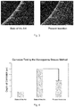
- Figure 3 presents two photographs showing the depth of intergranular corrosion following the implementation of the first test.
- the valve having conventional nitridation presents intergranular corrosion of up to 500 micrometres whilst the valve of the present invention presents corrosion of less than 300 micrometres.
- the areas of corrosion are represented by the whitish bands apparent in the photographs.
- Figure 4 represents graphically the results of the first corrosion test carried out. It may be observed that the valve not subjected to any process of hardening (state of the art 1) presents very low levels of corrosion, having a corrosion depth of 100 micrometres. It is important that it be recalled that those valves without heat treatment present high corrosion resistance, but low hardness and wear resistance.
- the valve subjected to the conventional process of nitridation presented high corrosion, having a depth of 500 micrometres.
- the valve of the present invention presenting a hardness exceeding 900 HV and high wear resistance, also presented high corrosion resistance, having a depth of less than 300 micrometres. Consequently, the valve of the present invention presents a depth of corrosion at least 40 % less than that presented by the valve subjected to the conventional nitridation.
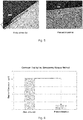
- Figure 5 presents two photographs showing the depth of corrosion following the implementation of a second corrosion test using method VDA 230-214 for metallic materials applied upon components subjected to the exhaust gases of the engine. It may be observed that the valve having conventional nitridation (state of the art) presents a visible band of corrosion having a depth exceeding 20 micrometres. In contrast, the valve of the present invention presents a minimal band of corrosion having a depth of less than 3 micrometres. These values of depth of corrosion are represented graphically in figure 6 .
- valve 1 which is the object of the present invention presents a series of advantages and benefits in relation to the valves presently known, these being:
Landscapes
- Chemical & Material Sciences (AREA)
- Engineering & Computer Science (AREA)
- Mechanical Engineering (AREA)
- Chemical Kinetics & Catalysis (AREA)
- Materials Engineering (AREA)
- Metallurgy (AREA)
- Organic Chemistry (AREA)
- General Engineering & Computer Science (AREA)
- Inorganic Chemistry (AREA)
- Solid-Phase Diffusion Into Metallic Material Surfaces (AREA)
Abstract
The present invention relates to a valve (1) for internal combustion engines wherein at least one region of the valve (1) comprises a nitrided layer (10) formed by a solid solution of nitrogen provided within the metallic matrix of the substrate (8) of the valve (1), the nitrided layer (10) being obtained by means of a heat treatment with diffusion of nitrogen, the nitrided layer (10) being provided with high hardness, conferring excellent wear resistance, in addition to high corrosion resistance, combining different properties in the valve (1).
Description
- The present invention relates to a valve for use in internal combustion engines wherein at least one region of the valve comprises a nitrided layer formed by up to 10 % by weight of nitrogen in solid solution provided in the metallic matrix of the valve, conferring excellent wear resistance, in addition to high corrosion resistance.
- The valves for use in internal combustion engines are high precision components submitted to high thermal and mechanical stresses. They are housed in the head(s) of the engine for the purpose of undertaking different tasks, such as perfectly and sealing areas of flow, controlling the exchange of gases, and sealing the cylinders from the exterior, in addition to dissipating the heat absorbed from the gases resulting from combustion, transferring it to a valve seat ring and to a valve guide.
- The valves are divided into inlet, controlling the intake of gaseous mixture into the cylinder of the engine, and exhaust, permitting the escape of the gases following the explosion. There is a generic difference between inlet and exhaust valves such that the inlet valves, cooled by the unburnt gases, need to resist high mechanical stresses, particularly in the contact thereof with the valve seat.
- The exhaust valves, in addition to great mechanical demands, also need to resist high thermal stresses and chemical corrosion. Furthermore, they work under temperatures ranging around 800 °C, opening and closing approximately 70 times per second, and are subjected to an average of 300 million load alternations.
- By virtue of the different stresses whereto a valve is subjected, the constructional configuration thereof is, in general, very similar. Consequently, as may be observed in
figure 1 , a valve is constituted by a head in disc form comprising a seating region and a neck region acting as transitional region to the stem, whilst at the extremity of the stem opposite to the head the tip of the valve is located. Moreover, in the region of the stem, adjacent to the tip of the valve, one or more neckings may be observed forming the grooves of the valve. Each region of the valve is submitted to different working conditions, being stressed as a consequence in a different manner. - In summary, the valves must be resistant to three different types of stress, mechanical, thermal and chemical. In relation to the mechanical strength, the valves must present resistance to impacts in the seating region and in the region of the tip. In terms of wear resistance, the principal parts affected are the seating region, the stem and the tip of the valve. In turn, resistance to pressure must be a characteristic of the face of the head. Finally fatigue strength is necessary by virtue of the constant alternation between the tensile and compression stresses.
- The requirement for thermal resistance arises from the temperature of combustion, from the high temperatures of the exhaust gases and from the fatigue caused by the alternation between high and low temperatures. Furthermore, chemical resistance is necessary to prevent the facility of corrosion in the corrosive environment of the gases, humidity and working temperatures to which the valve is subject.
- Current engines are, increasingly, stressed under extreme conditions, whether at high temperatures and/or speeds, the objective being to increase the fuel efficiency thereof and deliver greater power. As a consequence of these new stresses, the components of the engines, in particular the valves, present successive modifications, always with the objective of increasing the working life of these elements.
- In this manner, having the objective of overcoming the demanding working conditions whereto the valves are subjected, it is very common that the valves are monometallic of special alloys, bimetallic, or that they be provided with inserts.
- The monometallic valves are constructed of a single material and are applied in parts experiencing moderate demand. On the other hand, the bimetallic valves are applied in situations of greater demand, a specific material being applied for each part of the valve. Naturally, these valves have a higher cost by virtue of the manufacturing process thereof, presenting limitations and, consequently, not being justifiable for a great proportion of the applications.
- Up to the present time, among the most common solutions of coating engine valves in the state of the art is nitridation, conferring high hardness upon the surface of the valve by virtue of the formation of hard phases of nitrides/carbides, with the consequent increase of the wear strength thereof.
- However, nitridation also presents a great disadvantage in the sense that it diminishes the corrosion resistance of the valves. There exist two principal mechanisms inherent to the nitridation responsible for rendering the valves susceptible to corrosion:
- Depassivation: all the stainless steels, principal material of manufacture of the valves, comprise a film of oxide (Cr2O3), "passive" and rich in chromium, formed naturally upon the surface of the steel. In spite of the film having an insignificant thickness (from 1 to 5 nanometres), it is extremely adherent and chemically stable. The process of nitridation ruptures the passive film in order to render possible the diffusion of the nitrogen into the structure. This rupture of the passive film signifies that the steel loses its anticorrosive properties, in this manner diminishing the corrosion resistance of the material.
- Chromium depletion: the process of nitridation causes the depletion of the chromium of the solid solution comprised within the matrix of the steel, by virtue of the formation and precipitation of chromium nitrides. The chromium nitrides "rob" the chromium from the metallic matrix causing the diminution of the corrosion resistance of the nitrided surface, and may render the use of the steel unviable in many applications.
- In this respect, in spite of the nitridation process conferring high wear resistance on the valve, this also drastically lowers the corrosion resistance of the stainless steels, leaving the valves susceptible to corrosion in acidic environments.
- Whilst diverse attempts exist which endeavour to minimise the wear to which the valves are subject, the solutions of the state of the art do not offer an engine valve achieving, concomitantly, a superior performance in the matter of wear resistance and corrosion resistance.
- It is consequently necessary to obtain a valve for internal combustion engines receiving a heat treatment with diffusion of nitrogen in solid solution provided in the metallic matrix of the valve, conferring excellent wear strength and high corrosion resistance.
- A first object of the present invention is the provision of a valve for use in internal combustion engines receiving a heat treatment with diffusion of nitrogen in solid solution provided in a metallic matrix.
- The present invention furthermore has as object the provision of a valve provided with a nitrided layer comprising between 3 and 50 micrometres, having a hardness exceeding 900 HV in at least one region of the valve.
- Finally, the present invention has as object the provision of a valve presenting excellent wear resistance in general, in addition to high corrosion resistance, combining different properties in the valve.
- The objects of the present invention are achieved by a valve for internal combustion engines provided with a ferrous body or substrate comprising chromium, such that at least one region of the valve comprises a nitrided layer formed by up to 10 % by weight of nitrogen in solid solution provided in the metallic matrix of the substrate of the valve, the nitrided layer presenting a gradual transition of the percentage by weight of nitrogen, wherein the outermost portion of the nitrided layer presents 10 % by weight of nitrogen decreasing gradually until reaching the substrate of the valve, the nitrided layer comprising a thickness of between 3 and 50 micrometres and hardness exceeding 900 HV.
- The objects are furthermore achieved by a valve comprising a nitrided layer provided upon all the surfaces thereof, being preferentially an inlet valve.
- The present invention will, hereinafter, be described in greater detail on the basis of an example of embodiment represented in the figures. The figures show:
-
Figure 1 : schematic lateral view of a valve with all the parts constituting it; -
Figure 2 : schematic drawing and photograph of the nitrided layer provided upon the valve of the present invention; -
Figure 3 : photographs showing the difference in depth of corrosion between a valve of the state of the art and of the present invention in a first corrosion test; -
Figure 4 : graphic representation of the difference in depth of corrosion between valves of the state of the art and of the present invention for the first corrosion test; -
Figure 5 : photographs showing the difference in depth of corrosion between a valve of the state of the art and of the present invention in a second corrosion test; and -
Figure 6 : graphic representation of the difference in depth of corrosion between valves of the state of the art and of the present invention for the second corrosion test. - The present invention relates to a
valve 1 for internal combustion engines wherein at least one region of thevalve 1 comprises anitrided layer 10 formed by a solid solution of nitrogen provided in the metallic matrix of thesubstrate 8 of thevalve 1, the nitridedlayer 10 being obtained by means of a heat treatment with diffusion of nitrogen, comprising high hardness, conferring upon thevalve 1 excellent wear resistance in addition to high corrosion resistance, combining different properties in thevalve 1. - As aforementioned, the
valves 1 for use in internal combustion engines are components of high precision, housed in the head of the engine, responsible for different tasks and subjected to high thermal and mechanical stresses. - By virtue of these different loads and stresses to which the
valve 1 is submitted, the constructional configuration thereof is, in general, very similar. Consequently, as may be observed infigure 1 , avalve 1 is constituted of ahead 2 in the form of a disc comprising aseating region 3 and a neck region 4 acting as region of transition to thestem 5, whilst at the extremity of thestem 5 opposite to thehead 2 there is located thetip 6 of thevalve 1. Moreover, in the region of thestem 5, adjacent to thetip 6 of thevalve 1, one or more neckings may be observed forming thegrooves 7 of thevalve 1. - Among the materials utilised in the manufacture of the
valves 1 for internal combustion engines are, preferentially, the austenitic and martensitic stainless steels characterised by presenting excellent properties of corrosion resistance, having however low surface hardness and, consequently, low wear resistance. - In this respect, the processes of hardening by nitridation are commonly applied, increasing the surface hardness, however significantly prejudicing the corrosion resistance of the material by virtue of the intense precipitation of nitrides and carbides which impoverish the matrix of chromium.
- The process of nitridation consists, basically, in the addition of nitrogen, in the atomic form thereof, upon the surface of a metal, usually steel. The nitrogen tends to occupy the interstices of the crystalline structure, migrating by diffusion into the interior of the metal. Traditionally, the processes of nitridation applied to stainless steels utilise temperatures in the band between 500 °C and 600 °C in salt baths or are carried out under a reductive nitriding atmosphere obtained from the dissociation of ammonia gas.
- Differing from the valves traditionally obtained through nitridation processes, the
valve 1 of the present invention comprises anitrided layer 10 formed by solid solution having a very high concentration of nitrogen provided within the metallic matrix of thevalve 1, without the formation of the aforementioned undesirable nitrides.Figure 2 presents the structure of thenitrided layer 10 of thevalve 1 of the present invention. The metallographic test carried out revealed a nitrided layer of 8 micrometres devoid of the presence of nitrides. - The heat treatment utilised comprises low-temperature diffusion of the nitrogen, providing the hardening of the surface together with a method of depassivation which does not destroy the film of chromium oxide. In
figure 2 the film ofoxide 11 formed upon thenitrided layer 10 may be observed. In this manner there is formed upon the surface a new phase, a supersaturated and metastable solid solution of high hardness without the diminution of the corrosion resistance inherent to the stainless steels. The heat treatment with diffusion of nitrogen causes a modification to the surfaces of thevalve 1, transforming the structure of thesubstrate 8. - The
nitrided layer 10 presents a gradual transition, or a gradient, of percentage by weight of nitrogen contained in solid solution, comprising up to 10 % by weight of nitrogen in an outermost portion of thenitrided layer 10 and decreasing gradually until reaching thesubstrate 8 of thevalve 1. In the same manner, thenitrided layer 10 presents a gradient of hardness comprising a hardness of up to 2000 HV in the outermost portion of the nitrided layer and gradually decreasing. Preferentially, thenitrided layer 10 comprises a hardness exceeding 900 HV. - In this sense, the present invention presents a
valve 1 for internal combustion engines, particularly avalve 1 provided with a ferrous body wherein at least one region of thevalve 1 comprises anitrided layer 10, having the objective, principally, of increasing the wear resistance thereof together with increased corrosion resistance. - The
valve 1 which is the object of the present invention has as innovation the fact that received upon at least one of the parts thereof is anitrided layer 10 comprising nitrogen in a solid solution provided within the metallic matrix of the material. Thenitrided layer 10 is provided upon the totality of the ferrous body orsubstrate 8 of thevalve 1, provided with high hardness, not revealed by any document of the prior art, and confers upon thevalve 1 excellent wear resistance in addition to high corrosion resistance. - Moreover, according to the preferential embodiment, the
nitrided layer 10 is provided with a thickness of between 3 and 50 micrometres, preferentially provided with a thickness of between 3 and 35 micrometres, being obtained by a heat treatment rendering possible the addition of nitrogen in solid solution, in this manner there being obtained anitrided layer 10 of high hardness, without prejudicing the anticorrosive properties inherent to stainless steels. - In a preferable embodiment, the heat treatment for diffusion of nitrogen is realised at a temperature of less than 450 °C, having a period of duration of the process of 3 to 20 hours. The
nitrided layer 10 is obtained by the reaction of the atmosphere rich in nitrogen with the metallic matrix of thesubstrate 8, preventing the formation of nitrides. -
Figures 3 to 6 present results of corrosion tests realised upon thevalve 1 of the present invention. Two types of corrosion test were carried out, the first test being conducted by the Moneypenny Strauss method wherein the test piece of thevalve 1 is immersed in a solution of pentahydrated copper and sulphuric acid (CuSO4.5H2O). The results of the first corrosion test are presented infigures 3 and 4 wherein there are compared three possibilities of materials for the valves applied in internal combustion engines: - 1) State of the Art 1: stainless steel, austenitic or martensitic, without any surface hardness treatment;
- 2) State of the Art 2: stainless steel, austenitic or martensitic, submitted to a conventional process of hardening by nitridation;
- 3) Present Invention: stainless steel, austenitic or martensitic, subjected to the process of hardening by nitridation utilised in the present invention.
-
Figure 3 presents two photographs showing the depth of intergranular corrosion following the implementation of the first test. As may be observed, the valve having conventional nitridation (state of the art) presents intergranular corrosion of up to 500 micrometres whilst the valve of the present invention presents corrosion of less than 300 micrometres. The areas of corrosion are represented by the whitish bands apparent in the photographs. -
Figure 4 represents graphically the results of the first corrosion test carried out. It may be observed that the valve not subjected to any process of hardening (state of the art 1) presents very low levels of corrosion, having a corrosion depth of 100 micrometres. It is important that it be recalled that those valves without heat treatment present high corrosion resistance, but low hardness and wear resistance. The valve subjected to the conventional process of nitridation presented high corrosion, having a depth of 500 micrometres. In contrast, the valve of the present invention, presenting a hardness exceeding 900 HV and high wear resistance, also presented high corrosion resistance, having a depth of less than 300 micrometres. Consequently, the valve of the present invention presents a depth of corrosion at least 40 % less than that presented by the valve subjected to the conventional nitridation. -
Figure 5 presents two photographs showing the depth of corrosion following the implementation of a second corrosion test using method VDA 230-214 for metallic materials applied upon components subjected to the exhaust gases of the engine. It may be observed that the valve having conventional nitridation (state of the art) presents a visible band of corrosion having a depth exceeding 20 micrometres. In contrast, the valve of the present invention presents a minimal band of corrosion having a depth of less than 3 micrometres. These values of depth of corrosion are represented graphically infigure 6 . - It is important that it be noted that the results of the second corrosion test carried out show that the
valve 1 of the present invention presents a depth of corrosion 85 % less than the valve of the state of the art. - Consequently, both the corrosion tests carried out clearly demonstrate an improvement in the corrosion resistance of the valves of the present invention in relation to the valves subjected to the conventional nitridation.
- In summary, the
valve 1 which is the object of the present invention presents a series of advantages and benefits in relation to the valves presently known, these being: - I. Nitrided layer having high hardness, exceeding 900 HV, up to 2000 HV;
- II. Excellent wear resistance in combination with high corrosion resistance;
- III. Maintenance of the passive film of
oxide 11 of the material by virtue of the low temperature of diffusion of nitrogen in the solid solution into the metallic matrix of thesubstrate 8 ofvalve 1. - An example of a preferred embodiment having been described, it shall be understood that the scope of the present invention covers other possible variations being limited solely by the content of the appended claims, therein included the possible equivalents.
Claims (7)
- Valve for internal combustion engines provided with a ferrous body or substrate (8) comprising chromium, characterised in that at least one region of the valve (1) comprises a nitrided layer (10) formed by up to 10 % by weight of nitrogen in a solid solution provided within the metallic matrix of the substrate (8) of the valve (1).
- Valve according to Claim 1, characterised in that the nitrided layer (10) presents a gradual transition of the percentage by weight of nitrogen, wherein the outermost portion of the nitrided layer (10) presents 10 % by weight of nitrogen decreasing gradually until reaching the substrate (8) of the valve (1).
- Valve according to Claim 1, characterised in that it comprises a film of oxide (11) upon the nitrided layer (10).
- Valve according to Claim 1, characterised in that the nitrided layer (10) comprises a thickness varying between 3 micrometres and 50 micrometres.
- Valve according to Claim 1, characterised in that the nitrided layer (10) comprises a surface hardness exceeding 900 HV.
- Valve according to Claim 1, characterised in that the nitrided layer (10) is provided upon all the surfaces of the valve (1).
- Valve according to Claim 1, characterised in that it is an inlet valve (1).
Applications Claiming Priority (1)
| Application Number | Priority Date | Filing Date | Title |
|---|---|---|---|
| BR102015025727A BR102015025727A2 (en) | 2015-10-08 | 2015-10-08 | VALVE FOR INTERNAL COMBUSTION ENGINES |
Publications (1)
| Publication Number | Publication Date |
|---|---|
| EP3159427A1 true EP3159427A1 (en) | 2017-04-26 |
Family
ID=57103922
Family Applications (1)
| Application Number | Title | Priority Date | Filing Date |
|---|---|---|---|
| EP16192608.4A Withdrawn EP3159427A1 (en) | 2015-10-08 | 2016-10-06 | Valve for internal combustion engines |
Country Status (2)
| Country | Link |
|---|---|
| EP (1) | EP3159427A1 (en) |
| BR (1) | BR102015025727A2 (en) |
Citations (4)
| Publication number | Priority date | Publication date | Assignee | Title |
|---|---|---|---|---|
| EP0126323A2 (en) * | 1983-05-16 | 1984-11-28 | GILARDINI S.p.A. | Mechanical element for the combustion chamber of a diesel engine of the type comprising sliding surfaces having wear protective layers for the running-in phase, and method for obtaining these layers |
| US20020162523A1 (en) * | 2000-09-21 | 2002-11-07 | Motokata Ishihara | Sliding member and method of manufacturing thereof |
| KR20110104631A (en) * | 2010-03-17 | 2011-09-23 | 동아대학교 산학협력단 | High corrosion resistance and high hardness colored austenitic stainless steel and its manufacturing method |
| US20130220263A1 (en) * | 2012-02-24 | 2013-08-29 | Mahle International Gmbh | Valve system for controlling the charge exchange |
-
2015
- 2015-10-08 BR BR102015025727A patent/BR102015025727A2/en not_active Application Discontinuation
-
2016
- 2016-10-06 EP EP16192608.4A patent/EP3159427A1/en not_active Withdrawn
Patent Citations (4)
| Publication number | Priority date | Publication date | Assignee | Title |
|---|---|---|---|---|
| EP0126323A2 (en) * | 1983-05-16 | 1984-11-28 | GILARDINI S.p.A. | Mechanical element for the combustion chamber of a diesel engine of the type comprising sliding surfaces having wear protective layers for the running-in phase, and method for obtaining these layers |
| US20020162523A1 (en) * | 2000-09-21 | 2002-11-07 | Motokata Ishihara | Sliding member and method of manufacturing thereof |
| KR20110104631A (en) * | 2010-03-17 | 2011-09-23 | 동아대학교 산학협력단 | High corrosion resistance and high hardness colored austenitic stainless steel and its manufacturing method |
| US20130220263A1 (en) * | 2012-02-24 | 2013-08-29 | Mahle International Gmbh | Valve system for controlling the charge exchange |
Also Published As
| Publication number | Publication date |
|---|---|
| BR102015025727A2 (en) | 2017-05-02 |
Similar Documents
| Publication | Publication Date | Title |
|---|---|---|
| EP2551560B2 (en) | Piston ring | |
| US8430075B2 (en) | Superaustenitic stainless steel and method of making and use thereof | |
| JP6767398B2 (en) | Tribology system including valve seat ring and valve | |
| CN101548120B (en) | Valve device | |
| US10590812B2 (en) | Sliding mechanism | |
| EP3045555B1 (en) | Highly heat conductive piston ring for internal combustion engine | |
| JP2008533372A (en) | High temperature gas valve with anti-corrosion protection layer | |
| US8919316B2 (en) | Valve system for controlling the charge exchange | |
| US9683466B2 (en) | Valve for internal combustion engines and method for obtaining a valve | |
| EP1795785B1 (en) | Method of manufacturing metal gasket | |
| JP2000145542A (en) | Piston ring for direct injection diesel engine and combination | |
| KR20100066349A (en) | Gas exchange valve and method for manufacturing thereof | |
| EP1586668A1 (en) | Valve spring retainer made of titanium | |
| EP2921663B1 (en) | Valve for internal combustion engines | |
| EP2443266B1 (en) | Engine component comprising corrosion-protection layer and manufacturing method | |
| CN119948251B (en) | piston rings | |
| JP7518272B2 (en) | piston ring | |
| Doi et al. | Development of lightweight DLC coated valve lifter made from beta titanium alloy for motorcycles | |
| JP6472938B1 (en) | Pressure ring, internal combustion engine, wire for pressure ring, and method for manufacturing wire for pressure ring | |
| WO2019087562A1 (en) | Pressure ring, internal combustion engine, wire stock for pressure ring, and method of manufacturing wire stock for pressure ring | |
| JP2004190560A (en) | piston ring | |
| BR102015025727A2 (en) | VALVE FOR INTERNAL COMBUSTION ENGINES | |
| WO2015197497A1 (en) | Method for manufacturing a component of an internal-combustion engine |
Legal Events
| Date | Code | Title | Description |
|---|---|---|---|
| PUAI | Public reference made under article 153(3) epc to a published international application that has entered the european phase |
Free format text: ORIGINAL CODE: 0009012 |
|
| AK | Designated contracting states |
Kind code of ref document: A1 Designated state(s): AL AT BE BG CH CY CZ DE DK EE ES FI FR GB GR HR HU IE IS IT LI LT LU LV MC MK MT NL NO PL PT RO RS SE SI SK SM TR |
|
| AX | Request for extension of the european patent |
Extension state: BA ME |
|
| STAA | Information on the status of an ep patent application or granted ep patent |
Free format text: STATUS: THE APPLICATION IS DEEMED TO BE WITHDRAWN |
|
| 18D | Application deemed to be withdrawn |
Effective date: 20171027 |