EP3159244A1 - Vehicular steering system - Google Patents
Vehicular steering system Download PDFInfo
- Publication number
- EP3159244A1 EP3159244A1 EP16181242.5A EP16181242A EP3159244A1 EP 3159244 A1 EP3159244 A1 EP 3159244A1 EP 16181242 A EP16181242 A EP 16181242A EP 3159244 A1 EP3159244 A1 EP 3159244A1
- Authority
- EP
- European Patent Office
- Prior art keywords
- steering
- target
- control unit
- reaction force
- angle
- Prior art date
- Legal status (The legal status is an assumption and is not a legal conclusion. Google has not performed a legal analysis and makes no representation as to the accuracy of the status listed.)
- Withdrawn
Links
- 238000006243 chemical reaction Methods 0.000 claims abstract description 74
- 230000007246 mechanism Effects 0.000 claims abstract description 16
- 238000010586 diagram Methods 0.000 description 11
- 238000001514 detection method Methods 0.000 description 9
- 230000008859 change Effects 0.000 description 4
- 230000006870 function Effects 0.000 description 4
- 230000007935 neutral effect Effects 0.000 description 4
- 238000004804 winding Methods 0.000 description 4
- 238000000034 method Methods 0.000 description 3
- 230000001629 suppression Effects 0.000 description 3
- 230000004069 differentiation Effects 0.000 description 2
- 230000008569 process Effects 0.000 description 2
Images


Classifications
-
- B—PERFORMING OPERATIONS; TRANSPORTING
- B62—LAND VEHICLES FOR TRAVELLING OTHERWISE THAN ON RAILS
- B62D—MOTOR VEHICLES; TRAILERS
- B62D15/00—Steering not otherwise provided for
- B62D15/02—Steering position indicators ; Steering position determination; Steering aids
- B62D15/027—Parking aids, e.g. instruction means
-
- B—PERFORMING OPERATIONS; TRANSPORTING
- B62—LAND VEHICLES FOR TRAVELLING OTHERWISE THAN ON RAILS
- B62D—MOTOR VEHICLES; TRAILERS
- B62D6/00—Arrangements for automatically controlling steering depending on driving conditions sensed and responded to, e.g. control circuits
-
- B—PERFORMING OPERATIONS; TRANSPORTING
- B62—LAND VEHICLES FOR TRAVELLING OTHERWISE THAN ON RAILS
- B62D—MOTOR VEHICLES; TRAILERS
- B62D15/00—Steering not otherwise provided for
- B62D15/02—Steering position indicators ; Steering position determination; Steering aids
- B62D15/027—Parking aids, e.g. instruction means
- B62D15/0285—Parking performed automatically
-
- B—PERFORMING OPERATIONS; TRANSPORTING
- B62—LAND VEHICLES FOR TRAVELLING OTHERWISE THAN ON RAILS
- B62D—MOTOR VEHICLES; TRAILERS
- B62D5/00—Power-assisted or power-driven steering
- B62D5/001—Mechanical components or aspects of steer-by-wire systems, not otherwise provided for in this maingroup
- B62D5/005—Mechanical components or aspects of steer-by-wire systems, not otherwise provided for in this maingroup means for generating torque on steering wheel or input member, e.g. feedback
- B62D5/006—Mechanical components or aspects of steer-by-wire systems, not otherwise provided for in this maingroup means for generating torque on steering wheel or input member, e.g. feedback power actuated
-
- B—PERFORMING OPERATIONS; TRANSPORTING
- B62—LAND VEHICLES FOR TRAVELLING OTHERWISE THAN ON RAILS
- B62D—MOTOR VEHICLES; TRAILERS
- B62D5/00—Power-assisted or power-driven steering
- B62D5/04—Power-assisted or power-driven steering electrical, e.g. using an electric servo-motor connected to, or forming part of, the steering gear
- B62D5/0409—Electric motor acting on the steering column
Definitions
- the invention relates to a vehicular steering system in which a steering member operated for steering and a steering operation mechanism are not mechanically coupled together and in which the steering operation mechanism is driven by a steering operation motor.
- a steer-by-wire system has been proposed in which a steering wheel as a steering member and a steering operation mechanism are not mechanically coupled together such that a driving force of a steering operation motor controlled in accordance with operation of the steering wheel is transmitted to the steering operation mechanism.
- a parking assist apparatus has been proposed in which, when parked as in "parking in a garage” or “tandem parking", a vehicle is automatically parked at a target parking position without the need for a driver to steer the steering wheel.
- An object of the invention is to provide a vehicular steering system that uses a novel method to allow suppression of an unforeseen situation resulting from rotation of a steering member during automatic operation.
- An aspect of the invention provides a vehicular steering system in which a steering member operated for steering and a steering operation mechanism are not mechanically coupled together and in which the steering operation mechanism is driven by a steering operation motor.
- the vehicular steering system includes a reaction force motor that applies a reaction force to the steering member and a reaction force motor control unit that controls the reaction force motor.
- the reaction force motor control unit includes a current limiting unit that limits a current flowing through the reaction force motor to a predetermined value or smaller during automatic operation.
- FIG. 1 is a diagram illustrating a configuration of a vehicular steering system according to an embodiment of the invention.
- FIG. 1 depicts a configuration of a steer-by-wire system.
- a vehicular steering system 1 includes a steering wheel 2, a steering operation motor 3, and a steering gear 4.
- the steering wheel 2 is a steering member that is operated for steering by a driver.
- the steering operation motor 3 is driven in accordance with a rotating operation for the steering wheel 2.
- the steering gear 4 transmits a driving force of the steering operation motor 3 to a right and a left front wheels 5 serving as steered wheels.
- the steering wheel 2 and a steering operation mechanism 6 including the steering operation motor 3 are not mechanically coupled together, so that an operation torque applied to the steering wheel 2 is not mechanically transmitted to the steering operation mechanism 6.
- the steering operation motor 3 is controlled to be driven in accordance with the amount of operation (steering angle or steering torque) of the steering wheel 2 so that the wheels 5 are steered.
- the steering operation motor 3 includes an electric motor such as a brushless motor.
- the steering operation motor 3 includes a brushless motor.
- the steering operation motor 3 is provided with a rotation angle sensor 21 such as a resolver for detecting the rotation angle of a rotor of the steering operation motor 3.
- the steering gear 4 has a motion converting mechanism that converts a rotary motion of an output shaft of the steering operation motor 3 into a linear motion of a steering rod 7 (a linear motion in a lateral direction of the vehicle).
- the motion of the steering rod 7 is transmitted to tie rods 8 and to the wheels 5 via knuckle arms 9 to change a toe angle (steered angle) of the wheels 5.
- the steering operation mechanism 6 includes the steering operation motor 3, the steering gear 4, the steering rod 7, the tie rods 8, and the knuckle arms 9.
- the steering gear 4 a well-known steering gear may be used.
- a configuration of the steering gear 4 is not limited so long as the steering gear 4 allows the motion of the steering operation motor 3 to be transmitted to the wheels 5 so as to change the steered angle.
- rotation of the steering operation motor 3 in a forward direction changes the steered angle of the wheels 5 in such a direction that the vehicle turns right (right-turn direction).
- Rotation of the steering operation motor 3 in the opposite direction changes the steered angle of the wheels 5 in such a direction that the vehicle turns left (left-turn direction).
- the steering wheel 2 is coupled to a rotating shaft 10 rotatably supported on a vehicle body side.
- the rotating shaft 10 is provided with a reaction force motor 19 that generates a reaction force torque (operational reaction force) that acts on the steering wheel 2.
- the reaction force motor 19 includes an electric motor such as a brushless motor which has an output shaft integral with the rotating shaft 10.
- the reaction force motor 19 includes a brushless motor.
- the reaction force motor 19 is provided with a rotation angle sensor 22 such as a resolver for detecting the rotation angle of a rotor (rotor angle) of the reaction force motor 19.
- a steering angle sensor 11 is provided around the rotating shaft 10 to detect the rotation angle of the rotating shaft 10 (the steering angle ⁇ h of the steering wheel 2).
- the steering angle sensor 11 detects the amount of forward or backward rotations (rotation angle) of the rotating shaft 10 with respect to the neutral position (reference position) of the rotating shaft 10.
- the steering angle sensor 11 outputs the amount of clockwise rotation with respect to the neutral position, for example, as a positive value and outputs the amount of counterclockwise rotation with respect to the neutral position, for example, as a negative value.
- a torque sensor 12 is provided around the rotating shaft 10 to detect a steering torque Th applied to the steering wheel 2 by the driver.
- a torque for clockwise steering is detected as a positive value
- a torque for counterclockwise steering is detected as a negative value.
- the magnitude of the steering torque increases as the absolute value of the steering torque increases.
- a steered angle sensor 13 is provided near the steering gear 4 to detect the steered angle ⁇ of the wheels 5.
- the steered angle sensor 13 includes, for example, a potentiometer that detects the operation amount of the steering rod 7, which corresponds to the steered angle ⁇ .
- the vehicle is also provided with a vehicle speed sensor 14 for detecting a vehicle speed V, a yaw rate sensor 15 for detecting a yaw rate Yr, and the like.
- the steering angle sensor 11, the torque sensor 12, the vehicle speed sensor 14, the yaw rate sensor 15, and rotation angle sensors 21 and 22 are each connected to an electronic control unit (ECU) 30.
- the ECU 30 controls the steering operation motor 3 and the reaction force motor 19.
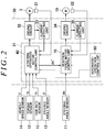
- FIG. 2 is a block diagram illustrating an electric configuration of the ECU 30.
- the ECU 30 includes a microcomputer 31, a driving circuit (inverter circuit) 32, a current detecting unit 33, a driving circuit (inverter circuit) 34, and a current detecting unit 35.
- the driving circuit 32 is controlled by the microcomputer 31 to supply power to the steering operation motor 3.
- the current detecting unit 33 detects a motor current flowing through the steering operation motor 3.
- the driving circuit 34 is controlled by the microcomputer 31 to supply power to the reaction force motor 19.
- the current detecting unit 35 detects a motor current flowing through the reaction force motor 19.
- the microcomputer 31 includes a CPU and memory (ROM, RAM, nonvolatile memory, and the like).
- the microcomputer 31 functions as a plurality of function processing units by executing predetermined programs.
- the function processing units include a steering operation motor control unit 40, a reaction force motor control unit 70, and an automatic-operation control unit 90.
- the steering operation motor control unit 40 controls the steering operation motor 3.
- the reaction force motor control unit 70 controls the reaction force motor 19.
- the automatic-operation control unit 90 allows a steering operation to be automatically performed regardless of operation of the steering wheel 2.
- the automatic-operation control unit 90 (parking assist apparatus) allows parking such as "parking in a garage” and "tandem parking" to be automatically performed.
- the automatic-operation control unit 90 may have, instead of or in addition to the parking assist apparatus, an automatic operation function other than the parking assist apparatus.
- a mode in which a steering operation is performed based on operation of the steering wheel 2 is sometimes referred to as a normal mode.
- a mode in which a steering operation is automatically performed by the automatic-operation control unit 90 is sometimes referred to as an automatic operation mode.
- the steering operation motor control unit 40 implements steering operation control in accordance with a steering state based on the vehicle speed V, the steering torque Th, the yaw rate Yr, and the steered angle ⁇ .
- the vehicle speed V is detected by the vehicle speed sensor 14.
- the steering torque Th is detected by the torque sensor 12.
- the yaw rate Yr is detected by the yaw rate sensor 15.
- the steered angle ⁇ is detected by the steered angle sensor 13.
- the steering operation motor control unit 40 implements automatic steering operation control by controlling the driving circuit 32 based on a target steering angle (target steered angle) and the steered angle ⁇ .
- the target steering angle is provided by the automatic-operation control unit 90.
- the reaction force motor control unit 70 implements reaction force control in accordance with the steering state by controlling the driving circuit 34 based on a target steering angle ⁇ h* and a steering angle ⁇ h.
- the target steering angle ⁇ h* is provided by the steering operation motor control unit 40.
- the steering angle ⁇ h is detected by the steering angle sensor 11.
- the steering operation motor 3 is, for example, a three-phase brushless motor.
- the steering operation motor 3 includes a rotor 100 serving as a field system and a stator 105 including stator windings 101, 102, and 103 for a U-phase, a V-phase, and a W-phase, respectively.
- the steering operation motor 3 may be of an inner rotor type in which a stator is arranged outside a rotor so as to face the rotor, or may be of an outer rotor type in which a stator is arranged inside a tubular rotor so as to face the rotor.
- a two-phase rotating coordinate system (a dq coordinate system or an actual rotating coordinate system) is defined in which a d-axis (magnetic-pole axis) is taken in a magnetic-pole direction of the rotor 100 and in which a q-axis (torque axis) is taken in a direction perpendicular to the d-axis in a rotating plane of the rotor 100.
- the dq coordinate system is a rotating coordinate system that rotates along with the rotor 100.
- the rotation angle (rotor angle (electrical angle)) ⁇ s of the rotor 100 is the rotation angle of the d-axis with respect to the U-axis.
- the dq coordinate system is an actual rotating coordinate system in accordance with the rotor angle ⁇ s .
- the use of the rotor angle ⁇ s allows coordinate conversion between the UVW coordinate system and the dq coordinate system.
- the reaction force motor 19 is, for example, a three-phase brushless motor and has a structure similar to that of the steering operation motor 3.
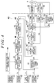
- FIG. 4 is a block diagram illustrating a configuration example of the steering operation motor control unit 40.
- the steering operation motor control unit 40 includes an angular-velocity calculating unit 41, a target steering angle calculating unit 42, a target steered angle calculating unit 43, an angular-deviation calculating unit 44, a proportional integral (PI) control unit 45, an angular-velocity deviation calculating unit 46, a PI control unit 47, a current deviation calculating unit 48, a PI control unit 49, dq/UVW converting unit 50, a pulse width modulation (PWM) control unit 51, a UVW/dq converting unit 52, and a rotation angle calculating unit 53.
- PWM pulse width modulation
- the target steering angle calculating unit 42 calculates the target steering angle ⁇ h*, which is a target value of the rotation angle of the rotating shaft 10, based on the vehicle speed V, the steering torque Th, and the yaw rate Yr.
- the vehicle speed V is detected by the vehicle speed sensor 14.
- the steering torque Th is detected by the torque sensor 12.
- the yaw rate Yr is detected by the yaw rate sensor 15.
- the target steering angle calculating unit 42 calculates the target steering angle ⁇ h* based on detection values indicative of the steering state (steering state detection value).
- the target steered angle calculating unit 43 calculates a target steered angle ⁇ * that is a target value of the steered angle, based on the target steering angle ⁇ h* calculated by the target steering angle calculating unit 42.
- the target steered angle ⁇ * calculated by the target steered angle calculating unit 43 is provided to the angular-deviation calculating unit 44.
- the PI control unit 45 executes PI calculation on the angular deviation ⁇ calculated by the angular-deviation calculating unit 44 to determine a target steered angle velocity ⁇ t* that is a target value of a steered angle velocity.
- the target steered angle velocity ⁇ t* calculated by the PI control unit 45 is provided to the angular-velocity deviation calculating unit 46.
- the angular-velocity calculating unit 41 executes time differentiation on the steered angle ⁇ detected by the steered angle sensor 13 to determine an angular velocity ⁇ t of the steered angle ⁇ (steered angle velocity).
- the steered angle velocity ⁇ t calculated by the angular-velocity calculating unit 41 is provided to the angular-velocity deviation calculating unit 46.
- the PI control unit 47 executes PI calculation on the steered angle deviation ⁇ t calculated by the angular-velocity deviation calculating unit 46 to determine target currents that are target values of currents to be passed through the coordinate axes of the dq coordinate system.
- the PI control unit 47 calculates a target d-axis current I d * and a target q-axis current I q * (hereinafter expressed as "target two-phase current I dq *" when collectively referred to). More specifically, the PI control unit 47 calculates the target q-axis current I q * such that the target q-axis current I q * has a significant value, while setting the target d-axis current I d * to zero.
- the target two-phase current I dq * calculated by the PI control unit 47 is provided to the current deviation calculating unit 48.
- the rotation angle calculating unit 53 calculates the rotation angle (electrical angle; hereinafter referred to as the "rotor angle ⁇ s ”) of the rotor of the steering operation motor 3 based on an output signal from the rotation angle sensor 21.
- the current detecting unit 33 detects a U-phase current I U , a V-phase current I V , and a W-phase current I W (hereinafter expressed as "three-phase detected current I UVW " when collectively referred to).
- the three-phase detected current I UVW detected by the current detecting unit 33 is provided to the UVW/dq converting unit 52.
- the UVW/dq converting unit 52 converts the three-phase detected current I UVW of the UVW coordinate system (the U-phase current I U , the V-phase current I V , and the W-phase current Iw), detected by the current detecting unit 33, into two-phase detected currents I d and Iq of the dq coordinate system (hereinafter expressed as "two-phase detected current I dq " when collectively referred to).
- the currents are provided to the current deviation calculating unit 48.
- the rotor angle ⁇ s calculated by the rotation angle calculating unit 53 is used for the coordinate conversion in the UVW/dq converting unit 52.
- the current deviation calculating unit 48 calculates a deviation between the target two-phase current I dq * calculated by the PI control unit 47 and the two-phase detected current I dq provided by the UVW/dq converting unit 52. More specifically, the current deviation calculating unit 48 calculates the deviation of a d-axis detected current I d with respect to the target d-axis current I d * and the deviation of a q-axis detected current Iq with respect to the target q-axis current I q *. The deviations are provided to the PI control unit 49.
- the PI control unit 49 executes PI calculation on the current deviation calculated by the current deviation calculating unit 48. This results in a target two-phase voltage V dq * (a target d-axis voltage V d * and a target q-axis voltage V q *) to be applied to the steering operation motor 3.
- the target two-phase voltage V dq * is provided to the dq/UVW converting unit 50.
- the dq/UVW converting unit 50 converts the target two-phase voltage V dq * into a target three-phase voltage V UVW *.
- the rotor angle ⁇ s calculated by the rotation angle calculating unit 53 is used for this coordinate conversion.
- the target three-phase voltage V UVW * is a combination of a target U-phase voltage V U *, a target V-phase voltage V V *, and a target W-phase voltage V W *.
- the target three-phase voltage V UVW * is provided to the PWM control unit 51.
- the PWM control unit 51 generates a U-phase PWM control signal, a V-phase PWM control signal, and a W-phase PWM control signal having duties corresponding to the target U-phase voltage V U *, the target V-phase voltage V V *, and the target W-phase voltage V W *, respectively, and supplies these PWM control signals to the driving circuit 32.
- the driving circuit 32 is a three-phase inverter circuit corresponding to the U-phase, the V-phase, and the W-phase. Power devices included in the inverter circuit are controlled using PWM control signals provided by the PWM control unit 51. Consequently, voltages corresponding to the target three-phase voltage V UVW * are applied to the stator windings 101, 102, and 103 for the respective phases in the steering operation motor 3.
- the angular-deviation calculating unit 44 and the PI control unit 45 are included in an angle feedback control unit.
- the angle feedback control unit acts to control the steered angle ⁇ of the wheels 5 so as to make the steered angle ⁇ closer to the target steered angle ⁇ * calculated by the target steered angle calculating unit 43.
- the angular-velocity deviation calculating unit 46 and the PI control unit 47 are included in an angular-velocity feedback control unit.
- the angular-velocity feedback control unit acts to control the steered angle velocity ⁇ t so as to make the steered angle velocity ⁇ t closer to the target steered angle velocity ⁇ t* calculated by the PI control unit 45.
- the current deviation calculating unit 48 and the PI control unit 49 are included in a current feedback control unit.
- the current feedback control unit acts to control a motor current flowing through the steering operation motor 3 so as to make the motor current closer to the target two-phase current I dq *, calculated by the PI control unit 47.
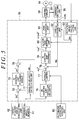
- FIG. 5 is a block diagram illustrating a configuration example of the reaction force motor control unit 70.
- the reaction force motor control unit 70 includes an angular-velocity calculating unit 71, an angular-deviation calculating unit 72, a PI control unit 73, an angular-velocity deviation calculating unit 75, a PI control unit 76, a torque limiter (current limiter) 77, a current deviation calculating unit 78, a PI control unit 79, a dq/UVW converting unit 80, a PWM control unit 81, a UVW/dq converting unit 82, and a rotation angle calculating unit 83.
- the target steering angle ⁇ h* is calculated by the target steering angle calculating unit 42 in the steering operation motor control unit 40.
- the steering angle ⁇ h is detected by the steering angle sensor 11.
- the PI control unit 73 executes PI calculation on the angular deviation ⁇ h calculated by the angular-deviation calculating unit 72. Consequently, a target steering angle velocity ⁇ h* is calculated which is a target value of a steering angle velocity.
- the target steering angle velocity ⁇ h* calculated by the PI control unit 73 is provided to the angular-velocity deviation calculating unit 75.
- the angular-velocity calculating unit 71 executes time differentiation on the steering angle ⁇ h detected by the steering angle sensor 11 to determine an angular velocity (steering angle velocity) ⁇ h of the steering angle ⁇ h.
- the steering angle velocity ⁇ h calculated by the angular-velocity calculating unit 71 is provided to the angular-velocity deviation calculating unit 75.
- the PI control unit 76 executes PI calculation on the angular-velocity deviation ⁇ h calculated by the angular-velocity deviation calculating unit 75. Consequently, target currents are calculated which are target values of currents to be passed through the coordinate axes of the dq coordinate system. Specifically, the PI control unit 76 calculates a target d-axis current i d * and a target q-axis current i q * (hereinafter expressed as "target two-phase current i dq *" when collectively referred to).
- the PI control unit 76 calculates the target q-axis current i q * such that the target q-axis current i q * has a significant value, while setting the target d-axis current i d * to zero.
- the target two-phase current i dq * calculated by the PI control unit 76 is provided to the torque limiter 77.
- the torque limiter 77 is controlled by the automatic-operation control unit 90. Specifically, the torque limiter 77 remains inactive in the normal mode. Therefore, in the normal mode, the target two-phase current i dq * calculated by the PI control unit 76 is provided to the current deviation calculating unit 78 without any change. In the automatic operation mode, the torque limiter 77 is made active by the automatic-operation control unit 90. In the automatic operation mode, the torque limiter 77 limits the absolute value of the target two-phase current i dq * (the absolute value of the target q-axis current i q *) calculated by the PI control unit 76 to a preset limit value ⁇ or smaller.
- the rotation angle calculating unit 83 calculates the rotation angle (electrical angle; hereinafter referred to as the "rotor angle ⁇ R ”) of the rotor of the reaction force motor 19 based on an output signal from the rotation angle sensor 22.
- the current detecting unit 35 detects a U-phase current i U , a V-phase current i V , and a W-phase current iw (hereinafter expressed as "three-phase detected current i UVW " when collectively referred to).
- the three-phase detected current i UVW detected by the current detecting unit 35 is provided to the UVW/dq converting unit 82.
- the UVW/dq converting unit 82 converts the three-phase detected current i UVW of the UVW coordinate system (the U-phase current i U , the V-phase current i V , and the W-phase current iw) detected by the current detecting unit 33 into two-phase detected currents i d and iq of the dq coordinate system (hereinafter expressed as the "two-phase detected current i dq " when collectively referred to).
- the currents are provided to the current deviation calculating unit 78.
- the rotor angle ⁇ R calculated by the rotation angle calculating unit 83, is used for the coordinate conversion in the UVW/dq converting unit 82.
- the current deviation calculating unit 78 calculates a deviation between the target two-phase current i dq * output from the torque limiter 77 and the two-phase detected current i dq provided by the UVW/dq converting unit 82. More specifically, the current deviation calculating unit 78 calculates the deviation of the d-axis detected current i d with respect to the target d-axis current i d * and the deviation of the q-axis detected current iq with respect to the target q-axis current i q *. The deviations are provided to the PI control unit 79.
- the PI control unit 79 executes PI calculation on the current deviation calculated by the current deviation calculating unit 78. This results in a target two-phase voltage v dq * (a target d-axis voltage v d * and a target q-axis voltage v q *) to be applied to the reaction force motor 19.
- the target two-phase voltage v dq * is provided to the dq/UVW converting unit 80.
- the dq/UVW converting unit 80 converts the target two-phase voltage v dq * into a target three-phase voltage v UVW *.
- the rotor angle ⁇ R calculated by the rotation angle calculating unit 83 is used for this coordinate conversion.
- the target three-phase voltage v UVW * is a combination of a target U-phase voltage v U *, a target V-phase voltage v V *, and a target W-phase voltage v W *.
- the target three-phase voltage v UVW * is provided to the PWM control unit 81.
- the PWM control unit 81 generates a U-phase PWM control signal, a V-phase PWM control signal, and a W-phase PWM control signal having respective duties corresponding to the target U-phase voltage v U *, the target V-phase voltage v V *, and the target W-phase voltage v W *, respectively, and supplies these PWM control signals to the driving circuit 34.
- the driving circuit 34 is a three-phase inverter circuit corresponding to the U-phase, the V-phase, and the W-phase. Power devices included in the inverter circuit are controlled using PWM control signals provided by the PWM control unit 81. Consequently, voltages corresponding to the target three-phase voltage v UVW * are applied to stator windings for the respective phases in the reaction force motor 19.
- the angular-deviation calculating unit 72 and the PI control unit 73 are included in an angle feedback control unit.
- the angle feedback control unit acts to control the rotation angle (steering angle) ⁇ h of the rotating shaft 10 so as to make the steering angle ⁇ h closer to the target steering angle ⁇ h* calculated by the target steering angle calculating unit 42.
- the angular-velocity deviation calculating unit 75 and the PI control unit 76 are included in an angular-velocity feedback control unit.
- the angular-velocity feedback control unit acts to control the steering angle velocity ⁇ h so as to make the steering angle velocity ⁇ h closer to the target steering angle velocity ⁇ h*.
- the current deviation calculating unit 78 and the PI control unit 79 are included in a current feedback control unit.
- the current feedback control unit acts to control a motor current flowing through the reaction force motor 19 so as to make the motor current closer to the target two-phase current I dq * output from the torque limiter 77.
- the target steering angle calculating unit 42 calculates the target steering angle ⁇ h*, which is a target value of the rotation angle of the rotating shaft 10, based on steering state detection values (in the present embodiment, the vehicle speed V, the steering torque Th, and the yaw rate Yr).
- the target steered angle calculating unit 43 calculates the target steered angle ⁇ * based on the target steering angle ⁇ h*.
- the steering operation motor 3 is controlled so as to make the steered angle ⁇ equal to the target steered angle ⁇ *.
- the reaction force motor 19 is controlled so as to make the steering angle ⁇ h equal to the target steering angle ⁇ h*.
- the automatic-operation control unit 90 sets the target steering angle ⁇ h* in the target steering angle calculating unit 42 in the steering operation motor control unit 40.
- the target steered angle calculating unit 43 calculates the target steered angle ⁇ * based on the target steering angle ⁇ h* set by the automatic-operation control unit 90.
- the steering operation motor 3 is controlled so as to make the steered angle ⁇ equal to the target steered angle ⁇ *. Consequently, the wheels 5 are automatically steered. In other words, in the present embodiment, automatic operation for parking assistance is performed.
- the torque limiter 77 limits the absolute value of the target two-phase current i dq * (the absolute value of the target q-axis current i q *), calculated by the PI control unit 76, to the preset limit value ⁇ or smaller.
- the torque applied to the steering wheel 2 by the reaction force motor 19 is limited. This allows suppression of an unforeseen situation resulting from rotation of the steering wheel 2 during automatic operation.
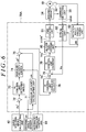
- FIG. 6 is a block diagram illustrating another configuration example of the reaction force motor control unit 70.
- Components in FIG. 6 that are similar to corresponding components in FIG. 5 described above are denoted by the same reference numerals as those in FIG. 5 .
- a reaction force motor control unit 70A in FIG. 6 is different from the reaction force motor control unit 70 in FIG. 5 in that the torque limiter 77 is not provided downstream of the PI control unit 76.
- the reaction force motor control unit 70A in FIG. 6 is different from the reaction force motor control unit 70 in FIG. 5 in that an angular-velocity limiter 74 is provided downstream of the PI control unit 73.
- the reaction force motor control unit 70A in FIG. 6 is otherwise the same as the reaction force motor control unit 70 in FIG. 5 .
- the angular-velocity limiter 74 is limited by the automatic-operation control unit 90. Specifically, the angular-velocity limiter 74 remains inactive in the normal mode. Therefore, in the normal mode, the target steering angle velocity ⁇ h*, calculated by the PI control unit 73, is provided to the angular-velocity deviation calculating unit 75 without any change. In the automatic operation mode, the angular-velocity limiter 74 is made active by the automatic-operation control unit 90. In the automatic operation mode, the angular-velocity limiter 74 limits the absolute value of the target steering angle velocity ⁇ h* calculated by the PI control unit 73 to a preset limit value ⁇ or smaller. Therefore, in the automatic operation mode, the target steering angle velocity ⁇ h* subjected to the limiting process by the angular-velocity limiter 74 is provided to the angular-velocity deviation calculating unit 75.
- the angular-velocity limiter 74 limits the absolute value of the target steering angle velocity ⁇ h* calculated by the PI control unit 73 to the limit value ⁇ or smaller.
- the rotation speed of the reaction force motor 19 is limited to a predetermined value or smaller. Consequently, during the automatic operation, the rotation speed of the steering wheel 2 is also limited to a predetermined value or smaller. This allows suppression of an unforeseen situation resulting from rotation of a steering member during automatic operation.
- the automatic-operation control unit 90 sets the target steering angle ⁇ h* in the target steering angle calculating unit 42 in the steering operation motor control unit 40 in the automatic operation mode.
- the automatic-operation control unit 90 may set the target steered angle ⁇ * in the target steered angle calculating unit 43 in the steering operation motor control unit 40.
- one of the reaction force motor control unit 70, 70A and the steering operation motor control unit 40 may calculate the target steering angle ⁇ h* based on the target steered angle ⁇ * set by the automatic-operation control unit 90, and provide the resultant target steering angle ⁇ h* to the angular-deviation calculating unit 72 in the reaction force motor control unit 70, 70A.
- the automatic-operation control unit 90 may generate and set the target steered angle ⁇ * in the target steered angle calculating unit 43 in the steering operation motor control unit 40, and generate and provide the target steering angle ⁇ h* to the angular-deviation calculating unit 72 in the reaction force motor control unit 70, 70A.
- the steering operation motor control unit 40 calculates the target steering angle ⁇ h* based on the steering state detection values such as the vehicle speed V, the steering torque Th, and the yaw rate Yr, and then calculates the target steered angle ⁇ * based on the resultant target steering angle ⁇ h*.
- the steering operation motor control unit 40 may directly calculate the target steered angle ⁇ * based on the steering state detection values.
- the reaction force motor control unit 70, 70A calculates the target steering angle ⁇ h* based on the target steered angle ⁇ * calculated by the steering operation motor control unit 40.
- the reaction force motor control unit 70, 70A calculates the target steering angle ⁇ h* based on the steering state detection values.
- the resultant target steering angle ⁇ h* may be provided to the angular-deviation calculating unit 72.
- the vehicle speed V, the steering torque Th, and the yaw rate Yr are used as the steering state detection values to calculate the target steering angle ⁇ h* (target steered angle ⁇ *).
- the steering state detection values are not limited to these detection values.
- the target steered angle velocity ⁇ t* is calculated based on the deviation between the target steered angle ⁇ * and the steered angle ⁇
- the target current I dq * is calculated based on the deviation between the target steered angle velocity ⁇ t* and the steered angle velocity ⁇ t.
- the steering operation motor control unit 40 may calculate the target current I dq * based on the deviation between the target steered angle ⁇ * and the steered angle ⁇ .
- the PI control unit 45, the angular-velocity deviation calculating unit 46, and the PI control unit 47 in FIG. 4 may be configured as a single PI control unit.
- the above-described reaction force motor control unit 70 in FIG. 5 calculates the target steering angle velocity ⁇ h* based on the deviation between the target steering angle ⁇ h* and the steering angle ⁇ h, and calculates the target current i dq * based on the deviation between the target steering angle velocity ⁇ h* and the steering angle velocity ⁇ h.
- the reaction force motor control unit 70 may calculate the target current i dq * based on the deviation between the target steering angle ⁇ h* and the steering angle ⁇ h.
- the PI control unit 73, the angular-velocity deviation calculating unit 75, and the PI control unit 76 in FIG. 5 may be configured as a single PI control unit.
Landscapes
- Engineering & Computer Science (AREA)
- Chemical & Material Sciences (AREA)
- Combustion & Propulsion (AREA)
- Transportation (AREA)
- Mechanical Engineering (AREA)
- Steering Control In Accordance With Driving Conditions (AREA)
Abstract
Description
- The invention relates to a vehicular steering system in which a steering member operated for steering and a steering operation mechanism are not mechanically coupled together and in which the steering operation mechanism is driven by a steering operation motor.
- A steer-by-wire system has been proposed in which a steering wheel as a steering member and a steering operation mechanism are not mechanically coupled together such that a driving force of a steering operation motor controlled in accordance with operation of the steering wheel is transmitted to the steering operation mechanism. A parking assist apparatus has been proposed in which, when parked as in "parking in a garage" or "tandem parking", a vehicle is automatically parked at a target parking position without the need for a driver to steer the steering wheel.
- In a vehicle with a steer-by-wire system mounted therein, while parking assistance (automatic steering operation) is being performed by the parking assist apparatus, the steering wheel rotates in synchronism with the automatic steering operation. At this time, an unforeseen situation may occur; for example, the driver's clothes may wrap around the steering wheel or the steering wheel may collide against the driver's hand. Thus, a parking assist apparatus for a vehicle with a steer-by-wire system mounted therein has been proposed which keeps the steering wheel in a neutral position while parking assistance is being performed (see Japanese Patent Application Publication No.
2012-40977 JP 2012-40977 A - An object of the invention is to provide a vehicular steering system that uses a novel method to allow suppression of an unforeseen situation resulting from rotation of a steering member during automatic operation.
- An aspect of the invention provides a vehicular steering system in which a steering member operated for steering and a steering operation mechanism are not mechanically coupled together and in which the steering operation mechanism is driven by a steering operation motor. The vehicular steering system includes a reaction force motor that applies a reaction force to the steering member and a reaction force motor control unit that controls the reaction force motor. The reaction force motor control unit includes a current limiting unit that limits a current flowing through the reaction force motor to a predetermined value or smaller during automatic operation.
- The foregoing and further features and advantages of the invention will become apparent from the following description of example embodiments with reference to the accompanying drawings, wherein like numerals are used to represent like elements and wherein:
-
FIG. 1 is a diagram illustrating a configuration of a vehicular steering system according to an embodiment of the invention; -
FIG. 2 is a block diagram illustrating an electric configuration of an ECU; -
FIG. 3 is a diagram illustrating a configuration of a steering operation motor; -
FIG. 4 is a block diagram illustrating a configuration example of a steering operation motor control unit; -
FIG. 5 is a block diagram illustrating a configuration example of a reaction force motor control unit; and -
FIG. 6 is a block diagram illustrating another configuration example of the reaction force motor control unit. - An embodiment of the invention will be described below in detail with reference to the attached drawings.
FIG. 1 is a diagram illustrating a configuration of a vehicular steering system according to an embodiment of the invention.FIG. 1 depicts a configuration of a steer-by-wire system. Avehicular steering system 1 includes asteering wheel 2, asteering operation motor 3, and asteering gear 4. Thesteering wheel 2 is a steering member that is operated for steering by a driver. Thesteering operation motor 3 is driven in accordance with a rotating operation for thesteering wheel 2. Thesteering gear 4 transmits a driving force of thesteering operation motor 3 to a right and a leftfront wheels 5 serving as steered wheels. Thesteering wheel 2 and asteering operation mechanism 6 including thesteering operation motor 3 are not mechanically coupled together, so that an operation torque applied to thesteering wheel 2 is not mechanically transmitted to thesteering operation mechanism 6. Thesteering operation motor 3 is controlled to be driven in accordance with the amount of operation (steering angle or steering torque) of thesteering wheel 2 so that thewheels 5 are steered. - The
steering operation motor 3 includes an electric motor such as a brushless motor. In the present embodiment, thesteering operation motor 3 includes a brushless motor. Thesteering operation motor 3 is provided with arotation angle sensor 21 such as a resolver for detecting the rotation angle of a rotor of thesteering operation motor 3. Thesteering gear 4 has a motion converting mechanism that converts a rotary motion of an output shaft of thesteering operation motor 3 into a linear motion of a steering rod 7 (a linear motion in a lateral direction of the vehicle). The motion of thesteering rod 7 is transmitted totie rods 8 and to thewheels 5 via knuckle arms 9 to change a toe angle (steered angle) of thewheels 5. In other words, thesteering operation mechanism 6 includes thesteering operation motor 3, thesteering gear 4, thesteering rod 7, thetie rods 8, and the knuckle arms 9. As thesteering gear 4, a well-known steering gear may be used. A configuration of thesteering gear 4 is not limited so long as thesteering gear 4 allows the motion of thesteering operation motor 3 to be transmitted to thewheels 5 so as to change the steered angle. - In the present embodiment, rotation of the
steering operation motor 3 in a forward direction changes the steered angle of thewheels 5 in such a direction that the vehicle turns right (right-turn direction). Rotation of thesteering operation motor 3 in the opposite direction changes the steered angle of thewheels 5 in such a direction that the vehicle turns left (left-turn direction). Thesteering wheel 2 is coupled to a rotatingshaft 10 rotatably supported on a vehicle body side. The rotatingshaft 10 is provided with areaction force motor 19 that generates a reaction force torque (operational reaction force) that acts on thesteering wheel 2. Thereaction force motor 19 includes an electric motor such as a brushless motor which has an output shaft integral with the rotatingshaft 10. In the present embodiment, thereaction force motor 19 includes a brushless motor. Thereaction force motor 19 is provided with arotation angle sensor 22 such as a resolver for detecting the rotation angle of a rotor (rotor angle) of thereaction force motor 19. - A
steering angle sensor 11 is provided around the rotatingshaft 10 to detect the rotation angle of the rotating shaft 10 (the steering angle θh of the steering wheel 2). In the present embodiment, thesteering angle sensor 11 detects the amount of forward or backward rotations (rotation angle) of the rotatingshaft 10 with respect to the neutral position (reference position) of therotating shaft 10. Thesteering angle sensor 11 outputs the amount of clockwise rotation with respect to the neutral position, for example, as a positive value and outputs the amount of counterclockwise rotation with respect to the neutral position, for example, as a negative value. - A
torque sensor 12 is provided around the rotatingshaft 10 to detect a steering torque Th applied to thesteering wheel 2 by the driver. In the present embodiment, for the steering torque Th detected by thetorque sensor 12, a torque for clockwise steering is detected as a positive value, and a torque for counterclockwise steering is detected as a negative value. The magnitude of the steering torque increases as the absolute value of the steering torque increases. - A steered
angle sensor 13 is provided near thesteering gear 4 to detect the steered angle δ of thewheels 5. The steeredangle sensor 13 includes, for example, a potentiometer that detects the operation amount of thesteering rod 7, which corresponds to the steered angle δ. The vehicle is also provided with avehicle speed sensor 14 for detecting a vehicle speed V, ayaw rate sensor 15 for detecting a yaw rate Yr, and the like. - The
steering angle sensor 11, thetorque sensor 12, thevehicle speed sensor 14, theyaw rate sensor 15, androtation angle sensors ECU 30 controls thesteering operation motor 3 and thereaction force motor 19.FIG. 2 is a block diagram illustrating an electric configuration of theECU 30. - The ECU 30 includes a
microcomputer 31, a driving circuit (inverter circuit) 32, acurrent detecting unit 33, a driving circuit (inverter circuit) 34, and acurrent detecting unit 35. Thedriving circuit 32 is controlled by themicrocomputer 31 to supply power to thesteering operation motor 3. The current detectingunit 33 detects a motor current flowing through thesteering operation motor 3. Thedriving circuit 34 is controlled by themicrocomputer 31 to supply power to thereaction force motor 19. The current detectingunit 35 detects a motor current flowing through thereaction force motor 19. - The
microcomputer 31 includes a CPU and memory (ROM, RAM, nonvolatile memory, and the like). Themicrocomputer 31 functions as a plurality of function processing units by executing predetermined programs. The function processing units include a steering operationmotor control unit 40, a reaction forcemotor control unit 70, and an automatic-operation control unit 90. The steering operationmotor control unit 40 controls thesteering operation motor 3. The reaction forcemotor control unit 70 controls thereaction force motor 19. The automatic-operation control unit 90 allows a steering operation to be automatically performed regardless of operation of thesteering wheel 2. In the present embodiment, the automatic-operation control unit 90 (parking assist apparatus) allows parking such as "parking in a garage" and "tandem parking" to be automatically performed. The automatic-operation control unit 90 may have, instead of or in addition to the parking assist apparatus, an automatic operation function other than the parking assist apparatus. A mode in which a steering operation is performed based on operation of thesteering wheel 2 is sometimes referred to as a normal mode. A mode in which a steering operation is automatically performed by the automatic-operation control unit 90 is sometimes referred to as an automatic operation mode. - In the normal mode, the steering operation
motor control unit 40 implements steering operation control in accordance with a steering state based on the vehicle speed V, the steering torque Th, the yaw rate Yr, and the steered angle δ. The vehicle speed V is detected by thevehicle speed sensor 14. The steering torque Th is detected by thetorque sensor 12. The yaw rate Yr is detected by theyaw rate sensor 15. The steered angle δ is detected by the steeredangle sensor 13. In the automatic operation mode, the steering operationmotor control unit 40 implements automatic steering operation control by controlling the drivingcircuit 32 based on a target steering angle (target steered angle) and the steered angle δ. The target steering angle is provided by the automatic-operation control unit 90. - The reaction force
motor control unit 70 implements reaction force control in accordance with the steering state by controlling the drivingcircuit 34 based on a target steering angle θh* and a steering angle θh. The target steering angle θh* is provided by the steering operationmotor control unit 40. The steering angle θh is detected by thesteering angle sensor 11. As illustrated inFIG. 3 , thesteering operation motor 3 is, for example, a three-phase brushless motor. Thesteering operation motor 3 includes arotor 100 serving as a field system and astator 105 includingstator windings steering operation motor 3 may be of an inner rotor type in which a stator is arranged outside a rotor so as to face the rotor, or may be of an outer rotor type in which a stator is arranged inside a tubular rotor so as to face the rotor. - Three-phase fixed coordinates (UVW coordinate system) are defined for which a U-axis, a V-axis, and a W-axis are taken in the directions of the
stator windings rotor 100 and in which a q-axis (torque axis) is taken in a direction perpendicular to the d-axis in a rotating plane of therotor 100. The dq coordinate system is a rotating coordinate system that rotates along with therotor 100. In the dq coordinate system, only a q-axis current contributes to torque generation performed by therotor 100. Consequently, the d-axis current may be set to zero, and the q-axis current may be controlled in accordance with a desired torque. The rotation angle (rotor angle (electrical angle)) θs of therotor 100 is the rotation angle of the d-axis with respect to the U-axis. The dq coordinate system is an actual rotating coordinate system in accordance with the rotor angle θs. The use of the rotor angle θs allows coordinate conversion between the UVW coordinate system and the dq coordinate system. - The
reaction force motor 19 is, for example, a three-phase brushless motor and has a structure similar to that of thesteering operation motor 3.FIG. 4 is a block diagram illustrating a configuration example of the steering operationmotor control unit 40. The steering operationmotor control unit 40 includes an angular-velocity calculating unit 41, a target steeringangle calculating unit 42, a target steeredangle calculating unit 43, an angular-deviation calculating unit 44, a proportional integral (PI)control unit 45, an angular-velocitydeviation calculating unit 46, aPI control unit 47, a currentdeviation calculating unit 48, aPI control unit 49, dq/UVW converting unit 50, a pulse width modulation (PWM)control unit 51, a UVW/dq converting unit 52, and a rotationangle calculating unit 53. - The target steering
angle calculating unit 42 calculates the target steering angle θh*, which is a target value of the rotation angle of therotating shaft 10, based on the vehicle speed V, the steering torque Th, and the yaw rate Yr. The vehicle speed V is detected by thevehicle speed sensor 14. The steering torque Th is detected by thetorque sensor 12. The yaw rate Yr is detected by theyaw rate sensor 15. In other words, the target steeringangle calculating unit 42 calculates the target steering angle θh* based on detection values indicative of the steering state (steering state detection value). - The target steered
angle calculating unit 43 calculates a target steered angle δ* that is a target value of the steered angle, based on the target steering angle θh* calculated by the target steeringangle calculating unit 42. The target steered angle δ* calculated by the target steeredangle calculating unit 43 is provided to the angular-deviation calculating unit 44. The angular-deviation calculating unit 44 calculates a deviation Δδ (= δ* - δ) between the target steered angle δ* calculated by the target steeredangle calculating unit 43 and the steered angle δ detected by the steeredangle sensor 13. - The
PI control unit 45 executes PI calculation on the angular deviation Δδ calculated by the angular-deviation calculating unit 44 to determine a target steered angle velocity ωt* that is a target value of a steered angle velocity. The target steered angle velocity ωt* calculated by thePI control unit 45 is provided to the angular-velocitydeviation calculating unit 46. The angular-velocity calculating unit 41 executes time differentiation on the steered angle δ detected by the steeredangle sensor 13 to determine an angular velocity ωt of the steered angle δ (steered angle velocity). The steered angle velocity ωt calculated by the angular-velocity calculating unit 41 is provided to the angular-velocitydeviation calculating unit 46. - The angular-velocity
deviation calculating unit 46 calculates a deviation Δωt (= ωt* - ωt) between the target steered angle velocity ωt* calculated by thePI control unit 45 and the steered angle velocity ωt calculated by the angular-velocity calculating unit 41. ThePI control unit 47 executes PI calculation on the steered angle deviation Δωt calculated by the angular-velocitydeviation calculating unit 46 to determine target currents that are target values of currents to be passed through the coordinate axes of the dq coordinate system. Specifically, thePI control unit 47 calculates a target d-axis current Id* and a target q-axis current Iq* (hereinafter expressed as "target two-phase current Idq*" when collectively referred to). More specifically, thePI control unit 47 calculates the target q-axis current Iq* such that the target q-axis current Iq* has a significant value, while setting the target d-axis current Id* to zero. The target two-phase current Idq* calculated by thePI control unit 47 is provided to the currentdeviation calculating unit 48. - The rotation
angle calculating unit 53 calculates the rotation angle (electrical angle; hereinafter referred to as the "rotor angle θs") of the rotor of thesteering operation motor 3 based on an output signal from therotation angle sensor 21. The current detectingunit 33 detects a U-phase current IU, a V-phase current IV, and a W-phase current IW (hereinafter expressed as "three-phase detected current IUVW" when collectively referred to). The three-phase detected current IUVW detected by the current detectingunit 33 is provided to the UVW/dq converting unit 52. - The UVW/
dq converting unit 52 converts the three-phase detected current IUVW of the UVW coordinate system (the U-phase current IU, the V-phase current IV, and the W-phase current Iw), detected by the current detectingunit 33, into two-phase detected currents Id and Iq of the dq coordinate system (hereinafter expressed as "two-phase detected current Idq" when collectively referred to). The currents are provided to the currentdeviation calculating unit 48. The rotor angle θs calculated by the rotationangle calculating unit 53 is used for the coordinate conversion in the UVW/dq converting unit 52. - The current
deviation calculating unit 48 calculates a deviation between the target two-phase current Idq* calculated by thePI control unit 47 and the two-phase detected current Idq provided by the UVW/dq converting unit 52. More specifically, the currentdeviation calculating unit 48 calculates the deviation of a d-axis detected current Id with respect to the target d-axis current Id* and the deviation of a q-axis detected current Iq with respect to the target q-axis current Iq*. The deviations are provided to thePI control unit 49. - The
PI control unit 49 executes PI calculation on the current deviation calculated by the currentdeviation calculating unit 48. This results in a target two-phase voltage Vdq* (a target d-axis voltage Vd* and a target q-axis voltage Vq*) to be applied to thesteering operation motor 3. The target two-phase voltage Vdq* is provided to the dq/UVW converting unit 50. The dq/UVW converting unit 50 converts the target two-phase voltage Vdq* into a target three-phase voltage VUVW*. The rotor angle θs calculated by the rotationangle calculating unit 53 is used for this coordinate conversion. The target three-phase voltage VUVW* is a combination of a target U-phase voltage VU*, a target V-phase voltage VV*, and a target W-phase voltage VW*. The target three-phase voltage VUVW* is provided to thePWM control unit 51. - The
PWM control unit 51 generates a U-phase PWM control signal, a V-phase PWM control signal, and a W-phase PWM control signal having duties corresponding to the target U-phase voltage VU*, the target V-phase voltage VV*, and the target W-phase voltage VW*, respectively, and supplies these PWM control signals to the drivingcircuit 32. The drivingcircuit 32 is a three-phase inverter circuit corresponding to the U-phase, the V-phase, and the W-phase. Power devices included in the inverter circuit are controlled using PWM control signals provided by thePWM control unit 51. Consequently, voltages corresponding to the target three-phase voltage VUVW* are applied to thestator windings steering operation motor 3. - The angular-
deviation calculating unit 44 and thePI control unit 45 are included in an angle feedback control unit. The angle feedback control unit acts to control the steered angle δ of thewheels 5 so as to make the steered angle δ closer to the target steered angle δ* calculated by the target steeredangle calculating unit 43. The angular-velocitydeviation calculating unit 46 and thePI control unit 47 are included in an angular-velocity feedback control unit. The angular-velocity feedback control unit acts to control the steered angle velocity ωt so as to make the steered angle velocity ωt closer to the target steered angle velocity ωt* calculated by thePI control unit 45. The currentdeviation calculating unit 48 and thePI control unit 49 are included in a current feedback control unit. The current feedback control unit acts to control a motor current flowing through thesteering operation motor 3 so as to make the motor current closer to the target two-phase current Idq*, calculated by thePI control unit 47. -
FIG. 5 is a block diagram illustrating a configuration example of the reaction forcemotor control unit 70. The reaction forcemotor control unit 70 includes an angular-velocity calculating unit 71, an angular-deviation calculating unit 72, aPI control unit 73, an angular-velocitydeviation calculating unit 75, aPI control unit 76, a torque limiter (current limiter) 77, a currentdeviation calculating unit 78, aPI control unit 79, a dq/UVW converting unit 80, aPWM control unit 81, a UVW/dq converting unit 82, and a rotationangle calculating unit 83. - The angular-
deviation calculating unit 72 calculates a deviation Δθh (= θh* - θh) between the target steering angle θh* and the steering angle θh. The target steering angle θh* is calculated by the target steeringangle calculating unit 42 in the steering operationmotor control unit 40. The steering angle θh is detected by thesteering angle sensor 11. ThePI control unit 73 executes PI calculation on the angular deviation Δθh calculated by the angular-deviation calculating unit 72. Consequently, a target steering angle velocity ωh* is calculated which is a target value of a steering angle velocity. The target steering angle velocity ωh* calculated by thePI control unit 73 is provided to the angular-velocitydeviation calculating unit 75. - The angular-
velocity calculating unit 71 executes time differentiation on the steering angle θh detected by thesteering angle sensor 11 to determine an angular velocity (steering angle velocity) ωh of the steering angle θh. The steering angle velocity ωh calculated by the angular-velocity calculating unit 71 is provided to the angular-velocitydeviation calculating unit 75. The angular-velocitydeviation calculating unit 75 calculates a deviation Δωh (= ωh* - ωh) between the target steering angle velocity ωh* calculated by thePI control unit 73 and the steering angle velocity ωh calculated by the angular-velocity calculating unit 71. - The
PI control unit 76 executes PI calculation on the angular-velocity deviation Δωh calculated by the angular-velocitydeviation calculating unit 75. Consequently, target currents are calculated which are target values of currents to be passed through the coordinate axes of the dq coordinate system. Specifically, thePI control unit 76 calculates a target d-axis current id* and a target q-axis current iq* (hereinafter expressed as "target two-phase current idq*" when collectively referred to). More specifically, thePI control unit 76 calculates the target q-axis current iq* such that the target q-axis current iq* has a significant value, while setting the target d-axis current id* to zero. The target two-phase current idq* calculated by thePI control unit 76 is provided to thetorque limiter 77. - The
torque limiter 77 is controlled by the automatic-operation control unit 90. Specifically, thetorque limiter 77 remains inactive in the normal mode. Therefore, in the normal mode, the target two-phase current idq* calculated by thePI control unit 76 is provided to the currentdeviation calculating unit 78 without any change. In the automatic operation mode, thetorque limiter 77 is made active by the automatic-operation control unit 90. In the automatic operation mode, thetorque limiter 77 limits the absolute value of the target two-phase current idq* (the absolute value of the target q-axis current iq*) calculated by thePI control unit 76 to a preset limit value α or smaller. This is to limit a torque generated by thereaction force motor 19 in the automatic operation mode to a predetermined value or smaller. Therefore, in the automatic operation mode, the target two-phase current idq* subjected to the limiting process by thetorque limiter 77 is provided to the currentdeviation calculating unit 78. - The rotation
angle calculating unit 83 calculates the rotation angle (electrical angle; hereinafter referred to as the "rotor angle θR") of the rotor of thereaction force motor 19 based on an output signal from therotation angle sensor 22. The current detectingunit 35 detects a U-phase current iU, a V-phase current iV, and a W-phase current iw (hereinafter expressed as "three-phase detected current iUVW" when collectively referred to). The three-phase detected current iUVW detected by the current detectingunit 35 is provided to the UVW/dq converting unit 82. - The UVW/
dq converting unit 82 converts the three-phase detected current iUVW of the UVW coordinate system (the U-phase current iU, the V-phase current iV, and the W-phase current iw) detected by the current detectingunit 33 into two-phase detected currents id and iq of the dq coordinate system (hereinafter expressed as the "two-phase detected current idq" when collectively referred to). The currents are provided to the currentdeviation calculating unit 78. The rotor angle θR, calculated by the rotationangle calculating unit 83, is used for the coordinate conversion in the UVW/dq converting unit 82. - The current
deviation calculating unit 78 calculates a deviation between the target two-phase current idq* output from thetorque limiter 77 and the two-phase detected current idq provided by the UVW/dq converting unit 82. More specifically, the currentdeviation calculating unit 78 calculates the deviation of the d-axis detected current id with respect to the target d-axis current id* and the deviation of the q-axis detected current iq with respect to the target q-axis current iq*. The deviations are provided to thePI control unit 79. - The
PI control unit 79 executes PI calculation on the current deviation calculated by the currentdeviation calculating unit 78. This results in a target two-phase voltage vdq* (a target d-axis voltage vd* and a target q-axis voltage vq*) to be applied to thereaction force motor 19. The target two-phase voltage vdq* is provided to the dq/UVW converting unit 80. The dq/UVW converting unit 80 converts the target two-phase voltage vdq* into a target three-phase voltage vUVW*. The rotor angle θR calculated by the rotationangle calculating unit 83 is used for this coordinate conversion. The target three-phase voltage vUVW* is a combination of a target U-phase voltage vU*, a target V-phase voltage vV*, and a target W-phase voltage vW*. The target three-phase voltage vUVW* is provided to thePWM control unit 81. - The
PWM control unit 81 generates a U-phase PWM control signal, a V-phase PWM control signal, and a W-phase PWM control signal having respective duties corresponding to the target U-phase voltage vU*, the target V-phase voltage vV*, and the target W-phase voltage vW*, respectively, and supplies these PWM control signals to the drivingcircuit 34. The drivingcircuit 34 is a three-phase inverter circuit corresponding to the U-phase, the V-phase, and the W-phase. Power devices included in the inverter circuit are controlled using PWM control signals provided by thePWM control unit 81. Consequently, voltages corresponding to the target three-phase voltage vUVW* are applied to stator windings for the respective phases in thereaction force motor 19. - The angular-
deviation calculating unit 72 and thePI control unit 73 are included in an angle feedback control unit. The angle feedback control unit acts to control the rotation angle (steering angle) θh of therotating shaft 10 so as to make the steering angle θh closer to the target steering angle θh* calculated by the target steeringangle calculating unit 42. The angular-velocitydeviation calculating unit 75 and thePI control unit 76 are included in an angular-velocity feedback control unit. The angular-velocity feedback control unit acts to control the steering angle velocity ωh so as to make the steering angle velocity ωh closer to the target steering angle velocity ωh*. The currentdeviation calculating unit 78 and thePI control unit 79 are included in a current feedback control unit. The current feedback control unit acts to control a motor current flowing through thereaction force motor 19 so as to make the motor current closer to the target two-phase current Idq* output from thetorque limiter 77. - In the normal mode, the target steering
angle calculating unit 42 calculates the target steering angle θh*, which is a target value of the rotation angle of therotating shaft 10, based on steering state detection values (in the present embodiment, the vehicle speed V, the steering torque Th, and the yaw rate Yr). The target steeredangle calculating unit 43 calculates the target steered angle δ* based on the target steering angle θh*. Thesteering operation motor 3 is controlled so as to make the steered angle δ equal to the target steered angle δ*. Thereaction force motor 19 is controlled so as to make the steering angle θh equal to the target steering angle θh*. Thus, the steering operation control and the reaction force control in accordance with operation of thesteering wheel 2 are performed. - In the automatic operation mode, the automatic-
operation control unit 90 sets the target steering angle θh* in the target steeringangle calculating unit 42 in the steering operationmotor control unit 40. The target steeredangle calculating unit 43 calculates the target steered angle δ* based on the target steering angle θh* set by the automatic-operation control unit 90. Thesteering operation motor 3 is controlled so as to make the steered angle δ equal to the target steered angle δ*. Consequently, thewheels 5 are automatically steered. In other words, in the present embodiment, automatic operation for parking assistance is performed. - For the reaction force
motor control unit 70, in the automatic operation mode, thetorque limiter 77 limits the absolute value of the target two-phase current idq* (the absolute value of the target q-axis current iq*), calculated by thePI control unit 76, to the preset limit value α or smaller. Thus, during the automatic operation, the torque applied to thesteering wheel 2 by thereaction force motor 19 is limited. This allows suppression of an unforeseen situation resulting from rotation of thesteering wheel 2 during automatic operation. -
FIG. 6 is a block diagram illustrating another configuration example of the reaction forcemotor control unit 70. Components inFIG. 6 that are similar to corresponding components inFIG. 5 described above are denoted by the same reference numerals as those inFIG. 5 . A reaction forcemotor control unit 70A inFIG. 6 is different from the reaction forcemotor control unit 70 inFIG. 5 in that thetorque limiter 77 is not provided downstream of thePI control unit 76. The reaction forcemotor control unit 70A inFIG. 6 is different from the reaction forcemotor control unit 70 inFIG. 5 in that an angular-velocity limiter 74 is provided downstream of thePI control unit 73. The reaction forcemotor control unit 70A inFIG. 6 is otherwise the same as the reaction forcemotor control unit 70 inFIG. 5 . - The angular-
velocity limiter 74 is limited by the automatic-operation control unit 90. Specifically, the angular-velocity limiter 74 remains inactive in the normal mode. Therefore, in the normal mode, the target steering angle velocity ωh*, calculated by thePI control unit 73, is provided to the angular-velocitydeviation calculating unit 75 without any change. In the automatic operation mode, the angular-velocity limiter 74 is made active by the automatic-operation control unit 90. In the automatic operation mode, the angular-velocity limiter 74 limits the absolute value of the target steering angle velocity ωh* calculated by thePI control unit 73 to a preset limit value β or smaller. Therefore, in the automatic operation mode, the target steering angle velocity ωh* subjected to the limiting process by the angular-velocity limiter 74 is provided to the angular-velocitydeviation calculating unit 75. - For the reaction force
motor control unit 70A, in the automatic operation mode, the angular-velocity limiter 74 limits the absolute value of the target steering angle velocity ωh* calculated by thePI control unit 73 to the limit value β or smaller. Thus, during the automatic operation, the rotation speed of thereaction force motor 19 is limited to a predetermined value or smaller. Consequently, during the automatic operation, the rotation speed of thesteering wheel 2 is also limited to a predetermined value or smaller. This allows suppression of an unforeseen situation resulting from rotation of a steering member during automatic operation. - The embodiment of the invention has been described. However, the invention may further be carried out in other forms. For example, in the above-described embodiment, the automatic-
operation control unit 90 sets the target steering angle θh* in the target steeringangle calculating unit 42 in the steering operationmotor control unit 40 in the automatic operation mode. However, in the automatic operation mode, the automatic-operation control unit 90 may set the target steered angle δ* in the target steeredangle calculating unit 43 in the steering operationmotor control unit 40. In this case, one of the reaction forcemotor control unit motor control unit 40 may calculate the target steering angle θh* based on the target steered angle δ* set by the automatic-operation control unit 90, and provide the resultant target steering angle θh* to the angular-deviation calculating unit 72 in the reaction forcemotor control unit - In the automatic operation mode, the automatic-
operation control unit 90 may generate and set the target steered angle δ* in the target steeredangle calculating unit 43 in the steering operationmotor control unit 40, and generate and provide the target steering angle θh* to the angular-deviation calculating unit 72 in the reaction forcemotor control unit motor control unit 40 calculates the target steering angle θh* based on the steering state detection values such as the vehicle speed V, the steering torque Th, and the yaw rate Yr, and then calculates the target steered angle δ* based on the resultant target steering angle θh*. However, the steering operationmotor control unit 40 may directly calculate the target steered angle δ* based on the steering state detection values. In this case, the reaction forcemotor control unit motor control unit 40. Alternatively, the reaction forcemotor control unit deviation calculating unit 72. - In the above-described embodiment, the vehicle speed V, the steering torque Th, and the yaw rate Yr are used as the steering state detection values to calculate the target steering angle θh* (target steered angle δ*). However, the steering state detection values are not limited to these detection values. In the above-described embodiment, the target steered angle velocity ωt* is calculated based on the deviation between the target steered angle δ* and the steered angle δ, and the target current Idq* is calculated based on the deviation between the target steered angle velocity ωt* and the steered angle velocity ωt. However, the steering operation
motor control unit 40 may calculate the target current Idq* based on the deviation between the target steered angle δ* and the steered angle δ. In this case, thePI control unit 45, the angular-velocitydeviation calculating unit 46, and thePI control unit 47 inFIG. 4 may be configured as a single PI control unit. - The above-described reaction force
motor control unit 70 inFIG. 5 calculates the target steering angle velocity ωh* based on the deviation between the target steering angle θh* and the steering angle θh, and calculates the target current idq* based on the deviation between the target steering angle velocity ωh* and the steering angle velocity ωh. However, the reaction forcemotor control unit 70 may calculate the target current idq* based on the deviation between the target steering angle θh* and the steering angle θh. In this case, thePI control unit 73, the angular-velocitydeviation calculating unit 75, and thePI control unit 76 inFIG. 5 may be configured as a single PI control unit. - Various changes may be made to the embodiment within the scope of the matters recited in the claims.
Claims (3)
- A vehicular steering system in which a steering member operated for steering and a steering operation mechanism are not mechanically coupled together and in which the steering operation mechanism is driven by a steering operation motor, the vehicular steering system comprising:a reaction force motor that applies a reaction force to the steering member; anda reaction force motor control unit that controls the reaction force motor, whereinthe reaction force motor control unit includes a current limiting unit that limits a current flowing through the reaction force motor to a predetermined value or smaller during automatic operation.
- A vehicular steering system in which a steering member operated for steering and a steering operation mechanism are not mechanically coupled together and in which the steering operation mechanism is driven by a steering operation motor, the vehicular steering system comprising:a reaction force motor that applies a reaction force to the steering member; anda reaction force motor control unit that controls the reaction force motor, whereinthe reaction force motor control unit includes a rotation speed limiting unit that limits a rotation speed of the reaction force motor to a predetermined value or smaller during automatic operation.
- The vehicular steering system according to claim 1 or 2, wherein the automatic operation is intended for parking assistance.
Applications Claiming Priority (1)
| Application Number | Priority Date | Filing Date | Title |
|---|---|---|---|
| JP2015148688A JP2017024683A (en) | 2015-07-28 | 2015-07-28 | Vehicular steering device |
Publications (1)
| Publication Number | Publication Date |
|---|---|
| EP3159244A1 true EP3159244A1 (en) | 2017-04-26 |
Family
ID=56550145
Family Applications (1)
| Application Number | Title | Priority Date | Filing Date |
|---|---|---|---|
| EP16181242.5A Withdrawn EP3159244A1 (en) | 2015-07-28 | 2016-07-26 | Vehicular steering system |
Country Status (4)
| Country | Link |
|---|---|
| US (1) | US10293856B2 (en) |
| EP (1) | EP3159244A1 (en) |
| JP (1) | JP2017024683A (en) |
| CN (1) | CN106394665A (en) |
Cited By (1)
| Publication number | Priority date | Publication date | Assignee | Title |
|---|---|---|---|---|
| WO2020064491A1 (en) * | 2018-09-24 | 2020-04-02 | Thyssenkrupp Presta Ag | Steer-by-wire steering gear with coupling rod supported on a pressure piece |
Families Citing this family (15)
| Publication number | Priority date | Publication date | Assignee | Title |
|---|---|---|---|---|
| GB2464413B (en) * | 2010-01-05 | 2014-07-02 | Protean Electric Ltd | Control Device for a Vehicle |
| GB201720363D0 (en) | 2017-12-06 | 2018-01-17 | Trw Ltd | Handwheel actuator assembly |
| JP7102749B2 (en) * | 2018-01-29 | 2022-07-20 | 株式会社ジェイテクト | Steering device |
| JP6874731B2 (en) * | 2018-04-11 | 2021-05-19 | トヨタ自動車株式会社 | Vehicle control device |
| US11603128B2 (en) | 2018-08-08 | 2023-03-14 | Nissan Motor Co., Ltd. | Steering control method and steering control device |
| CN109404454A (en) * | 2018-12-24 | 2019-03-01 | 重庆工业职业技术学院 | A kind of mechanical limiting mechanism |
| JP2020104540A (en) | 2018-12-26 | 2020-07-09 | 株式会社ジェイテクト | Vehicle control device |
| JP7115386B2 (en) * | 2019-03-27 | 2022-08-09 | トヨタ自動車株式会社 | vehicle controller |
| CN110077392B (en) * | 2019-03-28 | 2020-08-25 | 惠州市德赛西威汽车电子股份有限公司 | Dead reckoning method of automatic parking positioning system |
| US11479265B2 (en) | 2020-03-25 | 2022-10-25 | Baidu Usa Llc | Incremental lateral control system using feedbacks for autonomous driving vehicles |
| JP7488164B2 (en) * | 2020-09-17 | 2024-05-21 | 株式会社ジェイテクト | Steering gear |
| JP2022146537A (en) * | 2021-03-22 | 2022-10-05 | 本田技研工業株式会社 | Steering device |
| CN115610507B (en) * | 2021-07-16 | 2026-04-17 | 蜂巢智能转向系统(江苏)有限公司保定分公司 | A vehicle steering control method, device, vehicle, and readable storage medium. |
| JP7619910B2 (en) * | 2021-08-26 | 2025-01-22 | トヨタ自動車株式会社 | Steering system |
| CN119636893B (en) * | 2024-12-27 | 2025-09-26 | 长城汽车股份有限公司 | Vehicle motor control method, device, vehicle and storage medium |
Citations (6)
| Publication number | Priority date | Publication date | Assignee | Title |
|---|---|---|---|---|
| EP0854075A2 (en) * | 1997-01-21 | 1998-07-22 | Koyo Seiko Co., Ltd. | Steering apparatus for a vehicle. |
| DE102005004726A1 (en) * | 2005-02-02 | 2006-08-10 | Daimlerchrysler Ag | Method for execution of automatic control of steering intervention involves determination of dynamic threshold value for the set steering parameter whereby set steering parameter is limited for delimitation of reaction moment |
| JP2006264374A (en) * | 2005-03-22 | 2006-10-05 | Jtekt Corp | Vehicle steering system |
| US7971678B2 (en) * | 2007-02-05 | 2011-07-05 | Nissan Motor Co., Ltd. | Vehicle steering device and control method for vehicle steering device |
| JP2012040977A (en) | 2010-08-20 | 2012-03-01 | Suzuki Motor Corp | Parking support system |
| WO2014054474A1 (en) * | 2012-10-01 | 2014-04-10 | 日産自動車株式会社 | Stability control device |
Family Cites Families (24)
| Publication number | Priority date | Publication date | Assignee | Title |
|---|---|---|---|---|
| JPH04133860A (en) * | 1990-09-25 | 1992-05-07 | Honda Motor Co Ltd | Control method for vehicle steering system |
| JP2970125B2 (en) * | 1990-12-25 | 1999-11-02 | 株式会社デンソー | Front wheel steering device |
| JP3554841B2 (en) * | 1997-02-07 | 2004-08-18 | 光洋精工株式会社 | Car steering system |
| JP3311271B2 (en) * | 1997-07-01 | 2002-08-05 | 本田技研工業株式会社 | Vehicle steering control device |
| JP3937914B2 (en) * | 2002-05-14 | 2007-06-27 | トヨタ自動車株式会社 | Vehicle operating device |
| JP3941640B2 (en) * | 2002-09-18 | 2007-07-04 | 日産自動車株式会社 | VEHICLE DRIVE OPERATION ASSISTANCE DEVICE, VEHICLE DRIVE OPERATION ASSISTANCE METHOD, AND VEHICLE USING THE METHOD |
| JP3912279B2 (en) * | 2002-12-24 | 2007-05-09 | 三菱自動車工業株式会社 | Car with automatic steering control device |
| JP3875209B2 (en) * | 2003-04-22 | 2007-01-31 | 株式会社ジェイテクト | Steer-by-wire system and control program therefor |
| JP3882797B2 (en) * | 2003-08-08 | 2007-02-21 | 日産自動車株式会社 | VEHICLE DRIVE OPERATION ASSISTANCE DEVICE AND VEHICLE HAVING VEHICLE DRIVE OPERATION ASSISTANCE DEVICE |
| JP4425687B2 (en) * | 2004-04-08 | 2010-03-03 | 本田技研工業株式会社 | Steering device |
| JP4608948B2 (en) * | 2004-05-27 | 2011-01-12 | 日産自動車株式会社 | Vehicle steering system |
| JP4421426B2 (en) * | 2004-08-31 | 2010-02-24 | 本田技研工業株式会社 | Steering device |
| JP4876634B2 (en) * | 2006-03-01 | 2012-02-15 | 日産自動車株式会社 | Vehicle steering control device |
| JP4632093B2 (en) * | 2006-06-07 | 2011-02-16 | 株式会社ジェイテクト | Vehicle steering system |
| JP2008308120A (en) * | 2007-06-18 | 2008-12-25 | Jtekt Corp | Vehicle steering system |
| JP5403330B2 (en) * | 2009-02-25 | 2014-01-29 | アイシン精機株式会社 | Parking assistance device |
| US20110260887A1 (en) * | 2010-04-23 | 2011-10-27 | Ford Global Technologies, Llc | Vehicle park assist with steering centering |
| JP5212748B2 (en) * | 2010-09-29 | 2013-06-19 | アイシン精機株式会社 | Parking assistance device |
| US8994521B2 (en) * | 2011-06-29 | 2015-03-31 | GM Global Technology Operations LLC | Steering wheels for vehicle control in manual and autonomous driving |
| JP5807778B2 (en) * | 2011-09-15 | 2015-11-10 | 株式会社ジェイテクト | Steering device for cargo handling vehicle |
| CN103987614B (en) * | 2011-12-22 | 2016-04-13 | 日产自动车株式会社 | Vehicle steering control device and steering control method |
| CN104736417B (en) * | 2012-10-04 | 2017-03-01 | 日产自动车株式会社 | Runner control device |
| JP6137534B2 (en) * | 2013-04-03 | 2017-05-31 | 株式会社ジェイテクト | Vehicle steering system |
| JP6212987B2 (en) * | 2013-06-28 | 2017-10-18 | 日産自動車株式会社 | Steering control device |
-
2015
- 2015-07-28 JP JP2015148688A patent/JP2017024683A/en active Pending
-
2016
- 2016-07-21 US US15/215,761 patent/US10293856B2/en not_active Expired - Fee Related
- 2016-07-26 CN CN201610596317.5A patent/CN106394665A/en active Pending
- 2016-07-26 EP EP16181242.5A patent/EP3159244A1/en not_active Withdrawn
Patent Citations (7)
| Publication number | Priority date | Publication date | Assignee | Title |
|---|---|---|---|---|
| EP0854075A2 (en) * | 1997-01-21 | 1998-07-22 | Koyo Seiko Co., Ltd. | Steering apparatus for a vehicle. |
| DE102005004726A1 (en) * | 2005-02-02 | 2006-08-10 | Daimlerchrysler Ag | Method for execution of automatic control of steering intervention involves determination of dynamic threshold value for the set steering parameter whereby set steering parameter is limited for delimitation of reaction moment |
| JP2006264374A (en) * | 2005-03-22 | 2006-10-05 | Jtekt Corp | Vehicle steering system |
| US7971678B2 (en) * | 2007-02-05 | 2011-07-05 | Nissan Motor Co., Ltd. | Vehicle steering device and control method for vehicle steering device |
| JP2012040977A (en) | 2010-08-20 | 2012-03-01 | Suzuki Motor Corp | Parking support system |
| WO2014054474A1 (en) * | 2012-10-01 | 2014-04-10 | 日産自動車株式会社 | Stability control device |
| EP2905203A1 (en) * | 2012-10-01 | 2015-08-12 | Nissan Motor Co., Ltd | Stability control device |
Cited By (3)
| Publication number | Priority date | Publication date | Assignee | Title |
|---|---|---|---|---|
| WO2020064491A1 (en) * | 2018-09-24 | 2020-04-02 | Thyssenkrupp Presta Ag | Steer-by-wire steering gear with coupling rod supported on a pressure piece |
| US20220111887A1 (en) * | 2018-09-24 | 2022-04-14 | Thyssenkrupp Presta Ag | Steer-by-wire steering gear with coupling rod supported on a pressure piece |
| US12037057B2 (en) | 2018-09-24 | 2024-07-16 | Thyssenkrupp Presta Ag | Steer-by-wire steering gear with coupling rod supported on a pressure piece |
Also Published As
| Publication number | Publication date |
|---|---|
| US10293856B2 (en) | 2019-05-21 |
| US20170029013A1 (en) | 2017-02-02 |
| CN106394665A (en) | 2017-02-15 |
| JP2017024683A (en) | 2017-02-02 |
Similar Documents
| Publication | Publication Date | Title |
|---|---|---|
| US10293856B2 (en) | Vehicular steering system | |
| US10272941B2 (en) | Vehicle steering device | |
| EP2907729B1 (en) | Electric Power Steering Apparatus | |
| US9043091B2 (en) | Vehicle steering system | |
| US10494018B2 (en) | Steering device | |
| EP2599687B1 (en) | Vehicle steering system | |
| EP3315383B1 (en) | Steering device | |
| EP2177422B1 (en) | Vehicle steering apparatus | |
| US8855858B2 (en) | Motor control unit and vehicle steering system | |
| US8380398B2 (en) | Motor control unit and motor control unit for vehicle steering apparatus | |
| EP3483036B1 (en) | Steering control apparatus | |
| JP2010011709A (en) | Motor control device and vehicle-steering device comprising the same | |
| EP3254929B1 (en) | Vehicle steering system | |
| EP2597015B1 (en) | Hydraulic power steering system | |
| JP2015229385A (en) | Electric power steering device | |
| JP6764564B2 (en) | Motor control device | |
| JP5545465B2 (en) | Motor control device and vehicle steering device | |
| JP2019156110A (en) | Steering device for vehicle | |
| JP2018047876A (en) | Vehicle steering system | |
| JP2015077841A (en) | Electric power steering device |
Legal Events
| Date | Code | Title | Description |
|---|---|---|---|
| PUAI | Public reference made under article 153(3) epc to a published international application that has entered the european phase |
Free format text: ORIGINAL CODE: 0009012 |
|
| AK | Designated contracting states |
Kind code of ref document: A1 Designated state(s): AL AT BE BG CH CY CZ DE DK EE ES FI FR GB GR HR HU IE IS IT LI LT LU LV MC MK MT NL NO PL PT RO RS SE SI SK SM TR |
|
| AX | Request for extension of the european patent |
Extension state: BA ME |
|
| 17P | Request for examination filed |
Effective date: 20171024 |
|
| RBV | Designated contracting states (corrected) |
Designated state(s): AL AT BE BG CH CY CZ DE DK EE ES FI FR GB GR HR HU IE IS IT LI LT LU LV MC MK MT NL NO PL PT RO RS SE SI SK SM TR |
|
| 17Q | First examination report despatched |
Effective date: 20181121 |
|
| STAA | Information on the status of an ep patent application or granted ep patent |
Free format text: STATUS: THE APPLICATION IS DEEMED TO BE WITHDRAWN |
|
| 18D | Application deemed to be withdrawn |
Effective date: 20200623 |