EP3159232A1 - Brake monitoring system - Google Patents
Brake monitoring system Download PDFInfo
- Publication number
- EP3159232A1 EP3159232A1 EP16194324.6A EP16194324A EP3159232A1 EP 3159232 A1 EP3159232 A1 EP 3159232A1 EP 16194324 A EP16194324 A EP 16194324A EP 3159232 A1 EP3159232 A1 EP 3159232A1
- Authority
- EP
- European Patent Office
- Prior art keywords
- brake
- temperature
- brakes
- temperature data
- processor
- Prior art date
- Legal status (The legal status is an assumption and is not a legal conclusion. Google has not performed a legal analysis and makes no representation as to the accuracy of the status listed.)
- Granted
Links
Images


Classifications
-
- B—PERFORMING OPERATIONS; TRANSPORTING
- B64—AIRCRAFT; AVIATION; COSMONAUTICS
- B64D—EQUIPMENT FOR FITTING IN OR TO AIRCRAFT; FLIGHT SUITS; PARACHUTES; ARRANGEMENT OR MOUNTING OF POWER PLANTS OR PROPULSION TRANSMISSIONS IN AIRCRAFT
- B64D45/00—Aircraft indicators or protectors not otherwise provided for
-
- B—PERFORMING OPERATIONS; TRANSPORTING
- B60—VEHICLES IN GENERAL
- B60T—VEHICLE BRAKE CONTROL SYSTEMS OR PARTS THEREOF; BRAKE CONTROL SYSTEMS OR PARTS THEREOF, IN GENERAL; ARRANGEMENT OF BRAKING ELEMENTS ON VEHICLES IN GENERAL; PORTABLE DEVICES FOR PREVENTING UNWANTED MOVEMENT OF VEHICLES; VEHICLE MODIFICATIONS TO FACILITATE COOLING OF BRAKES
- B60T17/00—Component parts, details, or accessories of power brake systems not covered by groups B60T8/00, B60T13/00 or B60T15/00, or presenting other characteristic features
- B60T17/18—Safety devices; Monitoring
- B60T17/22—Devices for monitoring or checking brake systems; Signal devices
- B60T17/221—Procedure or apparatus for checking or keeping in a correct functioning condition of brake systems
-
- B—PERFORMING OPERATIONS; TRANSPORTING
- B64—AIRCRAFT; AVIATION; COSMONAUTICS
- B64C—AEROPLANES; HELICOPTERS
- B64C25/00—Alighting gear
- B64C25/32—Alighting gear characterised by elements which contact the ground or similar surface
- B64C25/42—Arrangement or adaptation of brakes
-
- F—MECHANICAL ENGINEERING; LIGHTING; HEATING; WEAPONS; BLASTING
- F16—ENGINEERING ELEMENTS AND UNITS; GENERAL MEASURES FOR PRODUCING AND MAINTAINING EFFECTIVE FUNCTIONING OF MACHINES OR INSTALLATIONS; THERMAL INSULATION IN GENERAL
- F16D—COUPLINGS FOR TRANSMITTING ROTATION; CLUTCHES; BRAKES
- F16D66/00—Arrangements for monitoring working conditions, e.g. wear, temperature
-
- B—PERFORMING OPERATIONS; TRANSPORTING
- B64—AIRCRAFT; AVIATION; COSMONAUTICS
- B64D—EQUIPMENT FOR FITTING IN OR TO AIRCRAFT; FLIGHT SUITS; PARACHUTES; ARRANGEMENT OR MOUNTING OF POWER PLANTS OR PROPULSION TRANSMISSIONS IN AIRCRAFT
- B64D45/00—Aircraft indicators or protectors not otherwise provided for
- B64D2045/0085—Devices for aircraft health monitoring, e.g. monitoring flutter or vibration
-
- F—MECHANICAL ENGINEERING; LIGHTING; HEATING; WEAPONS; BLASTING
- F16—ENGINEERING ELEMENTS AND UNITS; GENERAL MEASURES FOR PRODUCING AND MAINTAINING EFFECTIVE FUNCTIONING OF MACHINES OR INSTALLATIONS; THERMAL INSULATION IN GENERAL
- F16D—COUPLINGS FOR TRANSMITTING ROTATION; CLUTCHES; BRAKES
- F16D66/00—Arrangements for monitoring working conditions, e.g. wear, temperature
- F16D2066/001—Temperature
Definitions
- Brake temperature monitoring systems which may be utilized to indicate the health status of the aircraft brake system, or to indicate a problem with the brake system, may compare a measured brake temperature against a predetermined value. Another method may involve comparing the difference between brake temperatures for brakes on the same axle to a predetermined value. As accurate and early detection of possible mechanical faults in the brakes of an aircraft brake system is important for safety and airline service efficiency, improved methods of determining health status of the aircraft brake system are desired.
- a brake health monitoring system comprising: a temperature sensor system comprising a plurality of temperature sensors in thermal communication with a plurality of brakes; and a processor configured to receive temperature measurements of each of the plurality of brakes from the plurality of temperature sensors, the temperature measurements defined as a temperature data set, the processor further configured to calculate a temperature data centrality value based on the temperature data set, the processor further configured to calculate a temperature deviation value for each of the plurality of brakes based on the relative temperatures measured for each of the plurality of brakes compared to the temperature data centrality value, wherein the processor assigns a health status for each of the plurality of brakes.
- the processor assigns a health status for each of the plurality of brakes by analyzing the temperature deviation value for each of the plurality of brakes via a process control tool.
- each of the plurality of brakes is operatively coupled to a wheel of a landing gear of an aircraft.
- the temperature sensor system is configured to obtain multiple brake temperature data sets over multiple time instances. In one embodiment, the multiple time instances are separated by regular time intervals.
- the multiple brake temperature data sets are obtained from a single flight.
- the temperature sensor system is configured to obtain brake temperature data from a single flight.
- the brake temperature data is obtained post flight.
- each of the temperature measurements of each of the plurality of brakes is an extreme temperature of the specific brake.
- the brake health monitoring system further comprise multiple processors, wherein a communicator system is configured to transmit the temperature data set over the multiple processors via at least one of a wireless transmission, and a wired transmission.
- the temperature data centrality value comprises at least one of a median value, and a mean value.
- the temperature deviation value comprises one of an absolute difference value, or a ratio value.
- the processor assigns a health status via an individual moving range chart.
- a brake health monitoring system for monitoring a health status of a brake system of an aircraft, the brake health monitoring system comprising: at least one temperature sensor in thermal communication with a plurality of brakes of the brake system, the at least one temperature sensor configured to obtain a brake temperature data for the plurality of brakes, the brake temperature data comprising at least one brake temperature data set comprising a plurality of brake temperatures obtained at a specific time, wherein each brake temperature of the plurality of brake temperatures is associated with a specific brake of the plurality of brakes; at least one processor configured to receive the brake temperature data; a communicator system configured to transmit the brake temperature data from the at least one temperature sensor to the at least one processor; wherein the at least one processor is configured to determine a temperature data centrality value based on the brake temperature data; wherein the at least one processor is configured to compare the brake temperature data, with the temperature data centrality value, by the at least one processor, to generate a temperature deviation value data set comprising a plurality of deviation values, wherein each deviation
- the process control tool is an individual-moving range chart.
- the temperature data centrality value comprises at least one of a median value, and a mean value.
- the brake temperature data comprises multiple brake temperature data sets obtained over multiple time instances, and over at least one particular time of interest.
- a method of monitoring health of a braking system comprising: measuring temperatures of a plurality of brakes; calculating a centrality value for the measured temperatures, the centrality value based on the measured temperatures; and assigning a health status to each of the plurality of brakes based on a relationship between the centrality value and the measured temperature for each of the plurality of brakes.
- the method further comprises calculating deviations of each of the measured temperatures from the centrality value.
- the method further comprises indicating the health status for each of the plurality of brakes.
- the method further comprises measuring temperatures of a plurality of brakes over multiple time instances. In one embodiment, the multiple time instances are separated by regular time intervals.
- a brake monitoring system 301 for monitoring the health status of the brakes of an aircraft, the aircraft comprising a plurality of brakes, the brake monitoring system 301 comprising conducting a statistical comparison of a brake temperature against a temperature data centrality value based on temperature values recorded from the plurality of brakes.
- the statistical analysis may comprise utilizing a process control tool, such as an individual-moving range chart.
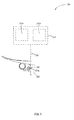
- an aircraft 304 may include one or more landing gears 302, each comprising one or more wheels 300, as shown in Figure 1 .
- the aircraft 304 comprises a brake system 303 which functions to slow the wheel 300, and hence the aircraft 304, such as, for example, during landing or a rejected take off.
- brake system 303 comprises a plurality (or "n" number) of brakes, B1, B2, B3,...
- each brake of the plurality of brakes is operatively coupled to a wheel 300 of one of the landing gears 302 of the aircraft 304.
- a brake monitoring system 301 shown in Figure 2 may comprise a temperature sensor system 306, configured to obtain brake temperature data from the brake system 303, at least one processor 201 configured to analyze brake temperature data received from temperature sensor system 306, and a communicator system 308 configured to communicate or transmit the brake temperature data from the temperature sensor system 306 to the at least one processor 201.
- the at least one processor 201 is configured to analyze brake temperature data via a brake monitoring method 100 (shown in Figure 3 ) in order to determine the health status of at least one brake of brake system 303.
- the at least one processor 201 is further configured to indicate the health status of the at least one brake.
- brake monitoring method 100 comprises conducting a statistical comparison of a brake temperature against a temperature data centrality value based on temperature values recorded from the plurality of brakes.
- the statistical analysis may comprise utilizing a process control tool, such as an individual-moving range chart.
- brake temperature data obtained by temperature sensor system 306, comprises at least one brake temperature data set 200.
- temperature sensor system 306 of brake monitoring system 301 comprises at least one temperature sensor (represented by temperature sensor 306a) in thermal communication with each brake Bi.
- temperature sensor system 306 comprises a plurality of temperature sensors 306a.
- temperature sensor 306a may be, for example, a thermocouple temperature sensor, an RTD, an infrared sensor, etc., according to various embodiments.
- temperature sensor 306a may be embedded in a component of the brake, such as the brake's torque tube, for example, to obtain the brake temperature BTi (or indication of the brake temperature, such as a voltage) of the brake.
- temperature sensor system 306 is configured to measure the brake temperature BTi of each brake Bi of the brake system 303, under similar conditions, such that the brake temperatures can be meaningfully compared.
- the brake temperatures, BTi, of the at least one brake temperature data set 200 are measured at the same time or at a specific time instance, according to various embodiments.
- the brake temperatures, BTi, of the at least one brake temperature data set 200 may be measured for all of the brakes, Bi, at an instant of time, or otherwise, over an amount of time sufficient to obtain a temperature indication or reading by the temperature sensor 306a, according to various embodiments.
- the brake temperatures, BTi, of the at least one brake temperature data set 200 may be measured over a prolonged time period, wherein, according to various embodiments, an extreme temperature reading over the time period may be registered as the brake temperature BTi for the specific brake Bi. According to various embodiments, such extreme temperature may comprise the hottest temperature registered over the prolonged time period.
- brake temperature data obtained by temperature sensor system 306 may comprise obtaining more than one or multiple brake temperature data sets 200 over multiple specific times or multiple time instances.
- the brake temperature data may comprise multiple brake temperature data sets 200 which are correlated to time.
- the times for obtaining multiple brake temperature data sets 200 may be separated by regular time intervals, the multiple brake temperature data sets 200 may be obtained over a specific time range comprising multiple time intervals. For example, a data set may be collected every 2 minutes, for 22 minutes, thus obtaining 11 data sets.
- brake temperature data 200 may be obtained at particular times of interest, including times during or shortly after the brakes Bi, of aircraft 304 may be used.
- particular times of interest for obtaining brake temperature data may include the time after a landing and/or rollout of the aircraft 304, taxing before takeoff, and shortly after takeoff, according to various embodiments.
- the at least one processor 201 is configured to analyze the brake temperature data, comprising the at least one brake temperature data set 200 obtained by temperature sensor system 306, via brake monitoring method 100, illustrated in Figure 3 .
- the at least one processor 201 carries out at least a step 104 of determining a temperature data centrality value ("CV") 202, a step 106 of comparing at least one brake temperature of the plurality of brake temperatures BTi, with the temperature data centrality value 202, and a step 108 of determining the health status of at least one brake, of brake monitoring method 100.
- CV temperature data centrality value
- step 104 of determining a temperature data centrality value ("CV") 202 is based on the at least one brake temperature data set 200 obtained by the temperature sensor system 306.
- the temperature data centrality value 202 may be the median brake temperature of the plurality of brake temperatures BTi, of the at least one brake temperature data set 200.
- the temperature data centrality value 202 may be the arithmetic mean brake temperature of the plurality of brake temperatures BTi, of the at least one brake temperature data set 200.
- Various method of obtaining median or arithmetic mean values are known in the art. Such methods may include, for example, excluding outlier values, obtaining a median average, etc., according to various embodiments. Additionally, other values representing a temperature data centrality value 202, and methods of derivation will be apparent to one skilled in the art.
- the step 106 of comparing at least one brake temperature of the plurality of brake temperatures BTi, with the temperature data centrality value 202 comprises obtaining a deviation value DV for the at least one brake temperature.
- step 106 comprises comparing each brake temperature BTi of the at least one brake temperature data set 200 against the temperature data centrality value 202, to generate at least one temperature deviation value data set 204, comprising a plurality of deviation values.
- ; DV2
- ; DV3
- ....DV4
- ; or DVi
- brake monitoring method 100 may comprise obtaining multiple temperature deviation value data sets 204 for multiple brake temperature data sets 200.
- the step 108 of determining the health status of at least one brake Bi of the brake system 303 comprises analyzing the at least one temperature deviation value data set 204 obtained in step 106.
- step 108 of determining the health status of at least one brake Bi may comprise determining the health status of all the brakes Bi of the brake system 303 of the aircraft 304.
- step 108 of determining the health status of at least one brake may comprise a process control analysis of the at least one temperature deviation value data set 204.
- step 108 of determining the health status of at least one brake Bi may comprise performing a statistical analysis on at least one temperature deviation value data set 204.
- the temperature deviation values set may be analyzed through a statistical process control tool comprising individual moving range chart (Shewhart chart). Such analysis may indicate whether the brake system is operating properly (i.e. is stable), or not, and may be used to determine the health status of each brake (i.e. based on its deviation value). Other methods of statistical analysis include other quality control tools may be apparent to one skilled in the art.
- the at least one temperature deviation value data set 204 may be obtained at a specific time instance.
- At least one temperature deviation value data set 204 may be obtained at a specific time of interest, such as post flight.
- multiple temperature deviation value data sets 204, which are correlated to time may be statistically analyzed.
- the multiple temperature deviation value data sets 204, which are correlated to time may be from a single flight.
- the multiple temperature deviation value data sets 204, which are correlated to time may be from multiple flights.
- the multiple temperature deviation value data sets 204, which are correlated to time may be from a single particular time of interests, or from multiple particular times of interests.
- the multiple temperature deviation value data sets 204, which are correlated to time may be from a single aircraft.
- the at least one processor 201 is further configured to indicate the health status of the at least one brake of the brake system 303.
- the at least one processor 201 may indicate the health status of each brake or of the brake system 303.
- the at least one processor may comprise a display unit, such as a cockpit display unit, for indicating brake health status.
- indicating brake health status of at least one brake Bi may comprise indicating a poor health status of any brake(s) found to have a poor health status, on a display device which may be a component of, or in communication with the at least one processor 201, according to various embodiments. Such indication may be relayed via multiple processors 201, via the communicator system 308, according to various embodiments.
- communicator system 308 of brake monitoring system 301 is configured to communicate or transmit the brake temperature data from temperature sensor system 306 to the at least one processor 201, via a wired transmission, a wireless transmission, or both a wireless and a wired transmission, according to various embodiments.
- a wired transmission may comprise at least one processor 201 on the aircraft 304.
- the at least one processor 201 may comprise multiple processors, wherein the brake temperature data may be transmitted via multiple processors 201, and may be transmitted both by wire and wirelessly.
- the brake temperature data may be transmitted by a wired connection to a first processor 201a on the aircraft 304, then wirelessly transmitted to a second processor 201b, which may be onboard the aircraft 304 or outside the aircraft 304, as shown in Figure 2 , according to various embodiments.
- the first processor 201 a may comprise a brake control unit on the aircraft 304, for example, which may convert a voltage produced by the temperature sensor system 306 of at least one brake Bi into a respective temperature reading that is communicated to the second processor 201b, according to various embodiments.
- the temperature sensor system 306 and the at least one processor 201 may comprise a single component which may perform both sensing and processing functions, according to various embodiments.
- the steps of brake monitoring method 100 may be carried out by the at least one processor 201, wherein the at least one processor may comprise a single processor on the aircraft 304 or off the aircraft 304, according to various embodiments. According to various embodiments, the steps of brake monitoring method 100 may be carried out by multiple processors 201, which may be on the aircraft 304, outside the aircraft 304, or both on the aircraft 304 and outside the aircraft 304, according to various embodiments.
- brake temperature data may be obtained via the temperature sensor system 306, and transmitted via communicator system 308 to a first processor 201a comprising a data concentrator on the aircraft 304, then provided to a second processor 201b comprising a central maintenance system, which may be on or off the aircraft 304, according to various embodiments, then either the second processor 201b, or a third processor, which may be on or off the aircraft may carry out the steps of brake monitoring method 100, according to various embodiments.
- references to "various embodiments”, “one embodiment”, “an embodiment”, “an example embodiment”, etc. indicate that the embodiment described may include a particular feature, structure, or characteristic, but every embodiment may not necessarily include the particular feature, structure, or characteristic. Moreover, such phrases are not necessarily referring to the same embodiment. Further, when a particular feature, structure, or characteristic is described in connection with an embodiment, it is submitted that it is within the knowledge of one skilled in the art to affect such feature, structure, or characteristic in connection with other embodiments whether or not explicitly described. After reading the description, it will be apparent to one skilled in the relevant art(s) how to implement the disclosure in alternative embodiments.
Landscapes
- Engineering & Computer Science (AREA)
- Mechanical Engineering (AREA)
- General Engineering & Computer Science (AREA)
- Aviation & Aerospace Engineering (AREA)
- Transportation (AREA)
- Valves And Accessory Devices For Braking Systems (AREA)
- Braking Arrangements (AREA)
Abstract
Description
- Brake temperature monitoring systems, which may be utilized to indicate the health status of the aircraft brake system, or to indicate a problem with the brake system, may compare a measured brake temperature against a predetermined value. Another method may involve comparing the difference between brake temperatures for brakes on the same axle to a predetermined value. As accurate and early detection of possible mechanical faults in the brakes of an aircraft brake system is important for safety and airline service efficiency, improved methods of determining health status of the aircraft brake system are desired.
- In accordance with various embodiments, disclosed is a brake health monitoring system, comprising: a temperature sensor system comprising a plurality of temperature sensors in thermal communication with a plurality of brakes; and a processor configured to receive temperature measurements of each of the plurality of brakes from the plurality of temperature sensors, the temperature measurements defined as a temperature data set, the processor further configured to calculate a temperature data centrality value based on the temperature data set, the processor further configured to calculate a temperature deviation value for each of the plurality of brakes based on the relative temperatures measured for each of the plurality of brakes compared to the temperature data centrality value, wherein the processor assigns a health status for each of the plurality of brakes. In one embodiment, the processor assigns a health status for each of the plurality of brakes by analyzing the temperature deviation value for each of the plurality of brakes via a process control tool. In one embodiment, each of the plurality of brakes is operatively coupled to a wheel of a landing gear of an aircraft. In one embodiment, the temperature sensor system is configured to obtain multiple brake temperature data sets over multiple time instances. In one embodiment, the multiple time instances are separated by regular time intervals. In one embodiment, the multiple brake temperature data sets are obtained from a single flight. In one embodiment, the temperature sensor system is configured to obtain brake temperature data from a single flight. In one embodiment, the brake temperature data is obtained post flight. In one embodiment, each of the temperature measurements of each of the plurality of brakes is an extreme temperature of the specific brake. In one embodiment, the brake health monitoring system further comprise multiple processors, wherein a communicator system is configured to transmit the temperature data set over the multiple processors via at least one of a wireless transmission, and a wired transmission. In one embodiment, the temperature data centrality value comprises at least one of a median value, and a mean value. In one embodiment, the temperature deviation value comprises one of an absolute difference value, or a ratio value. In one embodiment, the processor assigns a health status via an individual moving range chart.
- According to various embodiments, disclosed is a brake health monitoring system for monitoring a health status of a brake system of an aircraft, the brake health monitoring system comprising: at least one temperature sensor in thermal communication with a plurality of brakes of the brake system, the at least one temperature sensor configured to obtain a brake temperature data for the plurality of brakes, the brake temperature data comprising at least one brake temperature data set comprising a plurality of brake temperatures obtained at a specific time, wherein each brake temperature of the plurality of brake temperatures is associated with a specific brake of the plurality of brakes; at least one processor configured to receive the brake temperature data; a communicator system configured to transmit the brake temperature data from the at least one temperature sensor to the at least one processor; wherein the at least one processor is configured to determine a temperature data centrality value based on the brake temperature data; wherein the at least one processor is configured to compare the brake temperature data, with the temperature data centrality value, by the at least one processor, to generate a temperature deviation value data set comprising a plurality of deviation values,
wherein each deviation value of the plurality of deviation values is associated with a specific brake of the plurality of brakes; and wherein the at least one processor is configured to analyze the temperature deviation value data set via a process control tool. In one embodiment, the process control tool is an individual-moving range chart. In one embodiment, the temperature data centrality value comprises at least one of a median value, and a mean value. In one embodiment, the brake temperature data comprises multiple brake temperature data sets obtained over multiple time instances, and over at least one particular time of interest. - According to various embodiments, disclosed is a method of monitoring health of a braking system, comprising: measuring temperatures of a plurality of brakes; calculating a centrality value for the measured temperatures, the centrality value based on the measured temperatures; and assigning a health status to each of the plurality of brakes based on a relationship between the centrality value and the measured temperature for each of the plurality of brakes. In one embodiment, the method further comprises calculating deviations of each of the measured temperatures from the centrality value. In one embodiment, the method further comprises indicating the health status for each of the plurality of brakes. In one embodiment, the method further comprises measuring temperatures of a plurality of brakes over multiple time instances. In one embodiment, the multiple time instances are separated by regular time intervals.
- The drawings described herein are for illustration purposes only and are not intended to limit the scope of the present disclosure in any way. The present disclosure will become more fully understood from the detailed description and the accompanying drawings wherein:
-
Figure 1 shows an aircraft comprising a brake system, according to various embodiments; -
Figure 2 shows a brake temperature monitoring system, for the brake system of the aircraft ofFigure 1 , according to various embodiments; and -
Figure 3 is a flow chart for a brake monitoring method for the brake temperature monitoring system ofFigure 2 , according to various embodiments. - All ranges and ratio limits disclosed herein may be combined. It is to be understood that unless specifically stated otherwise, references to "a," "an," and/or "the" may include one or more than one and that reference to an item in the singular may also include the item in the plural.
- The detailed description of exemplary embodiments herein makes reference to the accompanying drawings, which show exemplary embodiments by way of illustration and its best mode, and not of limitation. While these exemplary embodiments are described in sufficient detail to enable those skilled in the art to practice the invention, it should be understood that other embodiments may be realized and that logical, chemical and mechanical changes may be made without departing from the spirit and scope of the invention. For example, the steps recited in any of the method or process descriptions may be executed in any order and are not necessarily limited to the order presented. Moreover, many of the functions or steps may be outsourced to or performed by one or more third parties. Furthermore, any reference to singular includes plural embodiments, and any reference to more than one component or step may include a singular embodiment or step. Also, any reference to attached, fixed, connected or the like may include permanent, removable, temporary, partial, full and/or any other possible attachment option. Additionally, any reference to without contact (or similar phrases) may also include reduced contact or minimal contact.
- In accordance with various embodiments, disclosed is a
brake monitoring system 301 for monitoring the health status of the brakes of an aircraft, the aircraft comprising a plurality of brakes, thebrake monitoring system 301 comprising conducting a statistical comparison of a brake temperature against a temperature data centrality value based on temperature values recorded from the plurality of brakes. According to various embodiments, the statistical analysis may comprise utilizing a process control tool, such as an individual-moving range chart. - According to various embodiments, and with reference to
Figure 1 , anaircraft 304 may include one ormore landing gears 302, each comprising one ormore wheels 300, as shown inFigure 1 . According to various embodiments, theaircraft 304 comprises abrake system 303 which functions to slow thewheel 300, and hence theaircraft 304, such as, for example, during landing or a rejected take off. According to various embodiments,brake system 303 comprises a plurality (or "n" number) of brakes, B1, B2, B3,... Bn; or Bi, where i=1, 2, 3,...n, (shown as B1, B2, B3, and B4 in the figure) wherein each brake of the plurality of brakes is operatively coupled to awheel 300 of one of thelanding gears 302 of theaircraft 304. - According to various embodiments, a
brake monitoring system 301 shown inFigure 2 , may comprise atemperature sensor system 306, configured to obtain brake temperature data from thebrake system 303, at least oneprocessor 201 configured to analyze brake temperature data received fromtemperature sensor system 306, and acommunicator system 308 configured to communicate or transmit the brake temperature data from thetemperature sensor system 306 to the at least oneprocessor 201. According to various embodiments, the at least oneprocessor 201 is configured to analyze brake temperature data via a brake monitoring method 100 (shown inFigure 3 ) in order to determine the health status of at least one brake ofbrake system 303. According to various embodiments, the at least oneprocessor 201 is further configured to indicate the health status of the at least one brake. - According to various embodiments,
brake monitoring method 100 comprises conducting a statistical comparison of a brake temperature against a temperature data centrality value based on temperature values recorded from the plurality of brakes. In various embodiments, the statistical analysis may comprise utilizing a process control tool, such as an individual-moving range chart. - According to various embodiments, brake temperature data obtained by
temperature sensor system 306, comprises at least one brake temperature data set 200. The at least one brake temperature data set 200 comprises a plurality (or "n" number) of brake temperatures, BT1, BT2, BT3...BTn (or BTi, where i=1, 2, 3,...n), obtained at a specific time instance, wherein each brake temperature, BTi, of the plurality of brake temperatures is associated with a specific brake Bi of the plurality of brakes of thebrake system 303. According to various embodiments,aircraft 304 may have eightwheels 300 each comprising a brake Bi, i=1,..., 8. Thus, according to various embodiments, the at least one brake temperature data set 200 may comprise 8 brake temperatures, BTi, (i=1, 2, 3, ..., 8). - According to various embodiments,
temperature sensor system 306 ofbrake monitoring system 301, comprises at least one temperature sensor (represented bytemperature sensor 306a) in thermal communication with each brake Bi. According to various embodiments,temperature sensor system 306 comprises a plurality oftemperature sensors 306a. According to various embodiments,temperature sensor 306a may be, for example, a thermocouple temperature sensor, an RTD, an infrared sensor, etc., according to various embodiments. According to various embodiments,temperature sensor 306a may be embedded in a component of the brake, such as the brake's torque tube, for example, to obtain the brake temperature BTi (or indication of the brake temperature, such as a voltage) of the brake. Under typical operating circumstances, the temperature of a brake will change over time, and different components of the brake will register different temperature measurements. Thus, according to various embodiments,temperature sensor system 306 is configured to measure the brake temperature BTi of each brake Bi of thebrake system 303, under similar conditions, such that the brake temperatures can be meaningfully compared. To that end, the brake temperatures, BTi, of the at least one brake temperature data set 200 are measured at the same time or at a specific time instance, according to various embodiments. Additionally, according to various embodiments, the brake temperatures, BTi (i=1...n), are measured from the same brake component (e.g., the torque tube) of each brake, Bi. According to various embodiments, the brake temperatures, BTi, of the at least one brake temperature data set 200 may be measured for all of the brakes, Bi, at an instant of time, or otherwise, over an amount of time sufficient to obtain a temperature indication or reading by thetemperature sensor 306a, according to various embodiments. According to various embodiments, the brake temperatures, BTi, of the at least one brake temperature data set 200 may be measured over a prolonged time period, wherein, according to various embodiments, an extreme temperature reading over the time period may be registered as the brake temperature BTi for the specific brake Bi. According to various embodiments, such extreme temperature may comprise the hottest temperature registered over the prolonged time period. - According to various embodiments, brake temperature data obtained by
temperature sensor system 306, may comprise obtaining more than one or multiple brake temperature data sets 200 over multiple specific times or multiple time instances. As such, the brake temperature data may comprise multiple brake temperature data sets 200 which are correlated to time. According to various embodiments, the times for obtaining multiple brake temperature data sets 200 may be separated by regular time intervals, the multiple brake temperature data sets 200 may be obtained over a specific time range comprising multiple time intervals. For example, a data set may be collected every 2 minutes, for 22 minutes, thus obtaining 11 data sets. - According to various embodiments, brake temperature data 200 may be obtained at particular times of interest, including times during or shortly after the brakes Bi, of
aircraft 304 may be used. For example, particular times of interest for obtaining brake temperature data may include the time after a landing and/or rollout of theaircraft 304, taxing before takeoff, and shortly after takeoff, according to various embodiments. - According to various embodiments, the at least one
processor 201 is configured to analyze the brake temperature data, comprising the at least one brake temperature data set 200 obtained bytemperature sensor system 306, viabrake monitoring method 100, illustrated inFigure 3 . According to various embodiments, the at least oneprocessor 201 carries out at least astep 104 of determining a temperature data centrality value ("CV") 202, astep 106 of comparing at least one brake temperature of the plurality of brake temperatures BTi, with the temperaturedata centrality value 202, and astep 108 of determining the health status of at least one brake, ofbrake monitoring method 100. - According to various embodiments, step 104 of determining a temperature data centrality value ("CV") 202 is based on the at least one brake temperature data set 200 obtained by the
temperature sensor system 306. According to various embodiments, the temperaturedata centrality value 202 may be the median brake temperature of the plurality of brake temperatures BTi, of the at least one brake temperature data set 200. According to various embodiments, the temperaturedata centrality value 202 may be the arithmetic mean brake temperature of the plurality of brake temperatures BTi, of the at least one brake temperature data set 200. Various method of obtaining median or arithmetic mean values are known in the art. Such methods may include, for example, excluding outlier values, obtaining a median average, etc., according to various embodiments. Additionally, other values representing a temperaturedata centrality value 202, and methods of derivation will be apparent to one skilled in the art. - According to various embodiments, the
step 106 of comparing at least one brake temperature of the plurality of brake temperatures BTi, with the temperaturedata centrality value 202, comprises obtaining a deviation value DV for the at least one brake temperature. According to various embodiments,step 106 comprises comparing each brake temperature BTi of the at least one brake temperature data set 200 against the temperaturedata centrality value 202, to generate at least one temperature deviationvalue data set 204, comprising a plurality of deviation values. According to various embodiments, the at least one temperature deviation value data set 204 comprises an "n" number of deviation values DV1, DV2, DV3...DVn, (or DVi, where i=1, 2, 3, ...n), wherein n is the number of brakes, wherein each deviation value is associated with a specific brake (i.e. B1, B2, B3,... Bn) of the at least one brake temperature data set 200, as shown inFigure 3 . According to various embodiments, thestep 106 of comparing each brake temperature, BTi, with the temperaturedata centrality value 202 obtained instep 104, and obtaining a deviation value DVi for each brake, may comprise determining an absolute difference between the temperaturedata centrality value 202 and each brake temperature, BTi, of the plurality of break temperatures, wherein DV1=|CV-BT1|; DV2=|CV-BT2| ; DV3=|CV-Bt3| ....DV4=|CV-BTn| ; or DVi=|CV-BTi|, where i=1→n, wherein the at least one temperature deviation value data set 204 is a temperature deviation data set comprising a plurality of deviations (DV1, DV2, DV3...DVn; or DVi, where i=1→n), wherein each deviation DVi of the plurality of deviations is associated with a brake, Bi, of the plurality of brakes (i.e. B1, B2, B3,... Bn; or Bi, where i=1,..n). According to various embodiments, obtaining a deviation value DVi for each brake, may comprise determining a ratio value, which may be a quotient or a multiple of a quotient between BTi and CV, i.e., DVi=BTi/CV or a multiple thereof, according to various embodiments. According to various embodiments,brake monitoring method 100 may comprise obtaining multiple temperature deviationvalue data sets 204 for multiple brake temperature data sets 200. - According to various embodiments, the
step 108 of determining the health status of at least one brake Bi of thebrake system 303, comprises analyzing the at least one temperature deviation value data set 204 obtained instep 106. According to various embodiments, step 108 of determining the health status of at least one brake Bi, may comprise determining the health status of all the brakes Bi of thebrake system 303 of theaircraft 304. According to various embodiments, step 108 of determining the health status of at least one brake may comprise a process control analysis of the at least one temperature deviationvalue data set 204. - According to various embodiments, step 108 of determining the health status of at least one brake Bi, may comprise performing a statistical analysis on at least one temperature deviation
value data set 204. According to various embodiments, the temperature deviation values set may be analyzed through a statistical process control tool comprising individual moving range chart (Shewhart chart). Such analysis may indicate whether the brake system is operating properly (i.e. is stable), or not, and may be used to determine the health status of each brake (i.e. based on its deviation value). Other methods of statistical analysis include other quality control tools may be apparent to one skilled in the art. According to various embodiments, the at least one temperature deviation value data set 204 may be obtained at a specific time instance. According to various embodiments, at least one temperature deviation value data set 204 may be obtained at a specific time of interest, such as post flight. According to various embodiments, multiple temperature deviationvalue data sets 204, which are correlated to time may be statistically analyzed. According to various embodiments, the multiple temperature deviationvalue data sets 204, which are correlated to time, may be from a single flight. According to various embodiments, the multiple temperature deviationvalue data sets 204, which are correlated to time, may be from multiple flights. According to various embodiments, the multiple temperature deviationvalue data sets 204, which are correlated to time, may be from a single particular time of interests, or from multiple particular times of interests. According to various embodiments, the multiple temperature deviationvalue data sets 204, which are correlated to time, may be from a single aircraft. - According to various embodiments, the at least one
processor 201 is further configured to indicate the health status of the at least one brake of thebrake system 303. According to various embodiments, the at least oneprocessor 201 may indicate the health status of each brake or of thebrake system 303. According to various embodiments, the at least one processor may comprise a display unit, such as a cockpit display unit, for indicating brake health status. According to various embodiments, indicating brake health status of at least one brake Bi may comprise indicating a poor health status of any brake(s) found to have a poor health status, on a display device which may be a component of, or in communication with the at least oneprocessor 201, according to various embodiments. Such indication may be relayed viamultiple processors 201, via thecommunicator system 308, according to various embodiments. - According to various embodiments,
communicator system 308 ofbrake monitoring system 301 is configured to communicate or transmit the brake temperature data fromtemperature sensor system 306 to the at least oneprocessor 201, via a wired transmission, a wireless transmission, or both a wireless and a wired transmission, according to various embodiments. According to various embodiments, a wired transmission, may comprise at least oneprocessor 201 on theaircraft 304. According to various embodiments, the at least oneprocessor 201 may comprise multiple processors, wherein the brake temperature data may be transmitted viamultiple processors 201, and may be transmitted both by wire and wirelessly. For example, the brake temperature data may be transmitted by a wired connection to afirst processor 201a on theaircraft 304, then wirelessly transmitted to asecond processor 201b, which may be onboard theaircraft 304 or outside theaircraft 304, as shown inFigure 2 , according to various embodiments. According to various embodiments, thefirst processor 201 a may comprise a brake control unit on theaircraft 304, for example, which may convert a voltage produced by thetemperature sensor system 306 of at least one brake Bi into a respective temperature reading that is communicated to thesecond processor 201b, according to various embodiments. According to various embodiments, thetemperature sensor system 306 and the at least oneprocessor 201 may comprise a single component which may perform both sensing and processing functions, according to various embodiments. - According to various embodiments, the steps of
brake monitoring method 100 may be carried out by the at least oneprocessor 201, wherein the at least one processor may comprise a single processor on theaircraft 304 or off theaircraft 304, according to various embodiments. According to various embodiments, the steps ofbrake monitoring method 100 may be carried out bymultiple processors 201, which may be on theaircraft 304, outside theaircraft 304, or both on theaircraft 304 and outside theaircraft 304, according to various embodiments. According to various embodiments, brake temperature data may be obtained via thetemperature sensor system 306, and transmitted viacommunicator system 308 to afirst processor 201a comprising a data concentrator on theaircraft 304, then provided to asecond processor 201b comprising a central maintenance system, which may be on or off theaircraft 304, according to various embodiments, then either thesecond processor 201b, or a third processor, which may be on or off the aircraft may carry out the steps ofbrake monitoring method 100, according to various embodiments. - Systems and methods are provided. In the detailed description herein, references to "various embodiments", "one embodiment", "an embodiment", "an example embodiment", etc., indicate that the embodiment described may include a particular feature, structure, or characteristic, but every embodiment may not necessarily include the particular feature, structure, or characteristic. Moreover, such phrases are not necessarily referring to the same embodiment. Further, when a particular feature, structure, or characteristic is described in connection with an embodiment, it is submitted that it is within the knowledge of one skilled in the art to affect such feature, structure, or characteristic in connection with other embodiments whether or not explicitly described. After reading the description, it will be apparent to one skilled in the relevant art(s) how to implement the disclosure in alternative embodiments.
- Benefits, other advantages, and solutions to problems have been described herein with regard to specific embodiments. However, the benefits, advantages, solutions to problems, and any elements that may cause any benefit, advantage, or solution to occur or become more pronounced are not to be construed as critical, required, or essential features or elements of the invention. The scope of the invention is accordingly to be limited by nothing other than the appended claims, in which reference to an element in the singular is not intended to mean "one and only one" unless explicitly so stated, but rather "one or more." Moreover, where a phrase similar to "at least one of A, B, or C" is used in the claims, it is intended that the phrase be interpreted to mean that A alone may be present in an embodiment, B alone may be present in an embodiment, C alone may be present in an embodiment, or that any combination of the elements A, B and C may be present in a single embodiment; for example, A and B, A and C, B and C, or A and B and C. Furthermore, no element, component, or method step in the present disclosure is intended to be dedicated to the public regardless of whether the element, component, or method step is explicitly recited in the claims. No claim element herein is to be construed under the provisions of 35 U.S.C. 112(f) unless the element is expressly recited using the phrase "means for." As used herein, the terms "comprises", "comprising", or any other variation thereof, are intended to cover a non-exclusive inclusion, such that a process, method, article, or apparatus that comprises a list of elements does not include only those elements but may include other elements not expressly listed or inherent to such process, method, article, or apparatus.
Claims (15)
- A brake health monitoring system (301), comprising:a temperature sensor system (306) comprising a plurality of temperature sensors in thermal communication with a plurality of brakes; anda processor (201) configured to receive temperature measurements of each of the plurality of brakes from the plurality of temperature sensors, the temperature measurements defined as a temperature data set, the processor (201) further configured to calculate a temperature data centrality value based on the temperature data set, the processor further configured to calculate a temperature deviation value for each of the plurality of brakes based on the relative temperatures measured for each of the plurality of brakes compared to the temperature data centrality value, wherein the processor (201) assigns a health status for each of the plurality of brakes.
- The brake health monitoring system of claim 1, wherein the processor (201) assigns a health status for each of the plurality of brakes by analyzing the temperature deviation value for each of the plurality of brakes via a process control tool, and/or wherein each of the plurality of brakes is operatively coupled to a wheel of a landing gear of an aircraft (304).
- The brake health monitoring system of claim 1 or 2, wherein the temperature sensor system (306) is configured to obtain multiple brake temperature data sets over multiple time instances.
- The brake health monitoring system of claim 3, wherein the temperature sensor system (306) is configured to obtain brake temperature data from a single flight, and preferably wherein the brake temperature data is obtained post flight.
- The brake health monitoring system of any preceding claim, wherein each of the temperature measurements of each of the plurality of brakes is an extreme temperature of the specific brake.
- The brake health monitoring system of any preceding claim, further comprising multiple processors, wherein a communicator system is configured to transmit the temperature data set over the multiple processors via at least one of a wireless transmission, and a wired transmission.
- The brake health monitoring system of any preceding claim, wherein the temperature data centrality value comprises at least one of a median value, and a mean value, and/or wherein the temperature deviation value comprises one of an absolute difference value, or a ratio value, and/or wherein the processor (201) assigns a health status via an individual moving range chart.
- A brake health monitoring system (301) for monitoring a health status of a brake system of an aircraft, the brake health monitoring system comprising:at least one temperature sensor (306a) in thermal communication with a plurality of brakes of the brake system, the at least one temperature sensor configured to obtain a brake temperature data for the plurality of brakes, the brake temperature data comprising at least one brake temperature data set (200) comprising a plurality of brake temperatures obtained at a specific time, wherein each brake temperature of the plurality of brake temperatures is associated with a specific brake of the plurality of brakes;at least one processor (201) configured to receive the brake temperature data;a communicator system (308) configured to transmit the brake temperature data from the at least one temperature sensor (306a) to the at least one processor (201);wherein the at least one processor (201) is configured to determine a temperature data centrality value based on the brake temperature data;wherein the at least one processor (201) is configured to compare the brake temperature data, with the temperature data centrality value, by the at least one processor (201), to generate a temperature deviation value data set comprising a plurality of deviation values, wherein each deviation value of the plurality of deviation values is associated with a specific brake of the plurality of brakes; andwherein the at least one processor (201) is configured to analyze the temperature deviation value data set via a process control tool.
- The brake health monitoring system of claim 8, wherein the process control tool is an individual-moving range chart.
- The brake health monitoring system of claim 8 or 9, wherein the temperature data centrality value comprises at least one of a median value, and a mean value.
- The brake health monitoring system of claim 8 or 9, wherein the brake temperature data comprises multiple brake temperature data sets obtained over multiple time instances, and over at least one particular time of interest.
- A method of monitoring health of a braking system, comprising:measuring temperatures of a plurality of brakes;calculating a centrality value for the measured temperatures, the centrality value based on the measured temperatures; andassigning a health status (108) to each of the plurality of brakes based on a relationship between the centrality value and the measured temperature for each of the plurality of brakes.
- The method of claim 12, further comprising calculating deviations of each of the measured temperatures from the centrality value.
- The method of claim 12 or 13, further comprising indicating the health status for each of the plurality of brakes.
- The method of claim 12, 13 or 14, further comprising measuring temperatures of a plurality of brakes over multiple time instances, and preferably wherein the multiple time instances are separated by regular time intervals.
Applications Claiming Priority (1)
| Application Number | Priority Date | Filing Date | Title |
|---|---|---|---|
| US14/887,069 US9789974B2 (en) | 2015-10-19 | 2015-10-19 | Brake monitoring system |
Publications (2)
| Publication Number | Publication Date |
|---|---|
| EP3159232A1 true EP3159232A1 (en) | 2017-04-26 |
| EP3159232B1 EP3159232B1 (en) | 2021-07-07 |
Family
ID=57777358
Family Applications (1)
| Application Number | Title | Priority Date | Filing Date |
|---|---|---|---|
| EP16194324.6A Active EP3159232B1 (en) | 2015-10-19 | 2016-10-18 | Brake monitoring system |
Country Status (2)
| Country | Link |
|---|---|
| US (1) | US9789974B2 (en) |
| EP (1) | EP3159232B1 (en) |
Cited By (3)
| Publication number | Priority date | Publication date | Assignee | Title |
|---|---|---|---|---|
| GB2572154A (en) * | 2018-03-19 | 2019-09-25 | Airbus Operations Ltd | Landing gear temperature characteristic |
| EP3659879A1 (en) * | 2018-11-30 | 2020-06-03 | Goodrich Corporation | Temperature monitoring to detect brake failure |
| US20220324429A1 (en) * | 2021-04-08 | 2022-10-13 | Arvinmeritor Technology, Llc | Brake system and method of monitoring |
Families Citing this family (6)
| Publication number | Priority date | Publication date | Assignee | Title |
|---|---|---|---|---|
| SG10202005892SA (en) | 2014-06-06 | 2020-07-29 | Herlev Hospital | Determining antigen recognition through barcoding of mhc multimers |
| US9926086B2 (en) * | 2016-05-26 | 2018-03-27 | The Boeing Company | Apparatus and method for wirelessly managing aircraft health data |
| GB2559329A (en) * | 2017-01-26 | 2018-08-08 | Airbus Operations Ltd | Fault detection based on brake torque and temperature |
| CN107389322B (en) * | 2017-06-26 | 2019-03-19 | 西安航空制动科技有限公司 | A low temperature test method for aircraft brake system |
| US11400900B2 (en) | 2020-03-03 | 2022-08-02 | Hamilton Sundstrand Corporation | Selective friction brake allocation during taxi |
| KR20220014032A (en) * | 2020-07-28 | 2022-02-04 | 현대자동차주식회사 | System and method for evaluating performance of vehicle device having friction parts |
Citations (5)
| Publication number | Priority date | Publication date | Assignee | Title |
|---|---|---|---|---|
| DE19713561C1 (en) * | 1997-04-02 | 1998-05-07 | Continental Ag | Electric braking system for motor vehicle |
| EP1359077A1 (en) * | 2002-04-29 | 2003-11-05 | WABCO GmbH & Co. OHG | Method and device for monitoring overload of brakes of electronically controlled brake systems of vehicles and vehicle combinations |
| US20060241819A1 (en) * | 2005-04-22 | 2006-10-26 | Greene Leonard M | Aircraft brake temperature monitoring system and method |
| US20100235065A1 (en) * | 2009-03-13 | 2010-09-16 | Gm Global Technology Operations, Inc. | Method for operating a vehicle brake system |
| DE102010016983A1 (en) * | 2010-05-18 | 2011-11-24 | Igor Padar | Brake assembly malfunction recognition method for vehicle, involves comparing temperatures at parts of assembly and/or temperature gradients of vehicle sides, and recognizing malfunction when determined deviation is above threshold value |
Family Cites Families (8)
| Publication number | Priority date | Publication date | Assignee | Title |
|---|---|---|---|---|
| US3582926A (en) * | 1968-04-08 | 1971-06-01 | Crane Co | Temperature indicator for aircraft brakes and the like |
| EP1970274B1 (en) * | 2000-08-04 | 2014-01-08 | Meggitt Aerospace Limited | Brake condition monitoring |
| CA2487704A1 (en) * | 2004-11-18 | 2006-05-18 | R. Kyle Schmidt | Method and system for health monitoring of aircraft landing gear |
| US8548652B2 (en) * | 2006-01-31 | 2013-10-01 | Hydro-Aire, Inc., Subsidiary Of Crane Co. | System for reducing carbon brake wear |
| US7766431B2 (en) * | 2006-12-22 | 2010-08-03 | The Boeing Company | System and method for an autobrake function for an aircraft electric brake system |
| US8712634B2 (en) * | 2010-08-11 | 2014-04-29 | The Boeing Company | System and method to assess and report the health of landing gear related components |
| FR3000004B1 (en) * | 2012-12-21 | 2016-12-23 | Messier Bugatti Dowty | METHOD FOR BRAKING AN AIRCRAFT |
| US9242739B2 (en) * | 2013-11-22 | 2016-01-26 | The Boeing Company | Methods to monitor components of an aircraft landing system |
-
2015
- 2015-10-19 US US14/887,069 patent/US9789974B2/en active Active
-
2016
- 2016-10-18 EP EP16194324.6A patent/EP3159232B1/en active Active
Patent Citations (5)
| Publication number | Priority date | Publication date | Assignee | Title |
|---|---|---|---|---|
| DE19713561C1 (en) * | 1997-04-02 | 1998-05-07 | Continental Ag | Electric braking system for motor vehicle |
| EP1359077A1 (en) * | 2002-04-29 | 2003-11-05 | WABCO GmbH & Co. OHG | Method and device for monitoring overload of brakes of electronically controlled brake systems of vehicles and vehicle combinations |
| US20060241819A1 (en) * | 2005-04-22 | 2006-10-26 | Greene Leonard M | Aircraft brake temperature monitoring system and method |
| US20100235065A1 (en) * | 2009-03-13 | 2010-09-16 | Gm Global Technology Operations, Inc. | Method for operating a vehicle brake system |
| DE102010016983A1 (en) * | 2010-05-18 | 2011-11-24 | Igor Padar | Brake assembly malfunction recognition method for vehicle, involves comparing temperatures at parts of assembly and/or temperature gradients of vehicle sides, and recognizing malfunction when determined deviation is above threshold value |
Cited By (5)
| Publication number | Priority date | Publication date | Assignee | Title |
|---|---|---|---|---|
| GB2572154A (en) * | 2018-03-19 | 2019-09-25 | Airbus Operations Ltd | Landing gear temperature characteristic |
| US11180130B2 (en) | 2018-03-19 | 2021-11-23 | Airbus Operations Limited | Landing gear temperature characteristic |
| EP3659879A1 (en) * | 2018-11-30 | 2020-06-03 | Goodrich Corporation | Temperature monitoring to detect brake failure |
| US20220324429A1 (en) * | 2021-04-08 | 2022-10-13 | Arvinmeritor Technology, Llc | Brake system and method of monitoring |
| US11938911B2 (en) * | 2021-04-08 | 2024-03-26 | Arvinmeritor Technology, Llc | Brake system and method of monitoring |
Also Published As
| Publication number | Publication date |
|---|---|
| US9789974B2 (en) | 2017-10-17 |
| US20170106995A1 (en) | 2017-04-20 |
| EP3159232B1 (en) | 2021-07-07 |
Similar Documents
| Publication | Publication Date | Title |
|---|---|---|
| EP3159232B1 (en) | Brake monitoring system | |
| JP6924647B2 (en) | Thermal event indicator for aircraft engines | |
| JP6176754B2 (en) | How to evaluate parts | |
| US11192664B2 (en) | Smart application for aircraft performance data collection | |
| EP2422204B1 (en) | System and method for detecting and isolating faults in pressure sensing of flush air data system (fads) | |
| US20180052452A1 (en) | Operating state acquisition apparatus, production management system, and production management method for manufacturing line | |
| US10422705B2 (en) | Apparatus and method for measuring body temperature of a human body | |
| CN108414113B (en) | Fire alarm system and method for predicting optical fiber temperature by using multipoint temperature discrete coefficients | |
| EP2981815B1 (en) | Device for measuring the thermal conductivity of gas components of a gas mixture | |
| US20160081629A1 (en) | Method and device for determining a core body temperature | |
| EP3392107A3 (en) | Brake health indicator systems using input and output energy | |
| US8478457B2 (en) | Fatigue management system | |
| MX2015003451A (en) | Diagnostic method for rail vehicles. | |
| US11061053B2 (en) | Measuring system and method | |
| JP2019505888A (en) | Method for monitoring at least two redundant sensors | |
| CN113665359A (en) | System and method for acquiring and processing speed signals of speedometer | |
| US20090306908A1 (en) | Device and method of monitoring an environmental parameter in real time | |
| US10311659B2 (en) | Method of analyzing variations of at least one indicator of the behavior of a mechanism fitted to an aircraft | |
| US10402236B2 (en) | Event-based data collection for smart sensors on an arbitrating bus | |
| CN109282854A (en) | A kind of on-line detecting system and method for electrical equipment | |
| CN108731792B (en) | Method for judging train passing and vibration detection device | |
| CN103942456A (en) | Measuring method and device capable of automatically judging wear position | |
| CN116151792A (en) | A CPS-based multi-rotor UAV health management system and method | |
| Chen et al. | Distributed information-based clustering of heterogeneous sensor data | |
| CN113034732B (en) | Method and device for diagnosing blockage of filter screen of traction converter |
Legal Events
| Date | Code | Title | Description |
|---|---|---|---|
| PUAI | Public reference made under article 153(3) epc to a published international application that has entered the european phase |
Free format text: ORIGINAL CODE: 0009012 |
|
| STAA | Information on the status of an ep patent application or granted ep patent |
Free format text: STATUS: THE APPLICATION HAS BEEN PUBLISHED |
|
| AK | Designated contracting states |
Kind code of ref document: A1 Designated state(s): AL AT BE BG CH CY CZ DE DK EE ES FI FR GB GR HR HU IE IS IT LI LT LU LV MC MK MT NL NO PL PT RO RS SE SI SK SM TR |
|
| AX | Request for extension of the european patent |
Extension state: BA ME |
|
| STAA | Information on the status of an ep patent application or granted ep patent |
Free format text: STATUS: REQUEST FOR EXAMINATION WAS MADE |
|
| 17P | Request for examination filed |
Effective date: 20171026 |
|
| RBV | Designated contracting states (corrected) |
Designated state(s): AL AT BE BG CH CY CZ DE DK EE ES FI FR GB GR HR HU IE IS IT LI LT LU LV MC MK MT NL NO PL PT RO RS SE SI SK SM TR |
|
| GRAP | Despatch of communication of intention to grant a patent |
Free format text: ORIGINAL CODE: EPIDOSNIGR1 |
|
| STAA | Information on the status of an ep patent application or granted ep patent |
Free format text: STATUS: GRANT OF PATENT IS INTENDED |
|
| INTG | Intention to grant announced |
Effective date: 20210210 |
|
| GRAS | Grant fee paid |
Free format text: ORIGINAL CODE: EPIDOSNIGR3 |
|
| GRAA | (expected) grant |
Free format text: ORIGINAL CODE: 0009210 |
|
| STAA | Information on the status of an ep patent application or granted ep patent |
Free format text: STATUS: THE PATENT HAS BEEN GRANTED |
|
| AK | Designated contracting states |
Kind code of ref document: B1 Designated state(s): AL AT BE BG CH CY CZ DE DK EE ES FI FR GB GR HR HU IE IS IT LI LT LU LV MC MK MT NL NO PL PT RO RS SE SI SK SM TR |
|
| REG | Reference to a national code |
Ref country code: GB Ref legal event code: FG4D |
|
| REG | Reference to a national code |
Ref country code: AT Ref legal event code: REF Ref document number: 1408297 Country of ref document: AT Kind code of ref document: T Effective date: 20210715 |
|
| REG | Reference to a national code |
Ref country code: DE Ref legal event code: R096 Ref document number: 602016060241 Country of ref document: DE |
|
| REG | Reference to a national code |
Ref country code: IE Ref legal event code: FG4D |
|
| REG | Reference to a national code |
Ref country code: LT Ref legal event code: MG9D |
|
| REG | Reference to a national code |
Ref country code: NL Ref legal event code: MP Effective date: 20210707 |
|
| REG | Reference to a national code |
Ref country code: AT Ref legal event code: MK05 Ref document number: 1408297 Country of ref document: AT Kind code of ref document: T Effective date: 20210707 |
|
| PG25 | Lapsed in a contracting state [announced via postgrant information from national office to epo] |
Ref country code: LT Free format text: LAPSE BECAUSE OF FAILURE TO SUBMIT A TRANSLATION OF THE DESCRIPTION OR TO PAY THE FEE WITHIN THE PRESCRIBED TIME-LIMIT Effective date: 20210707 Ref country code: BG Free format text: LAPSE BECAUSE OF FAILURE TO SUBMIT A TRANSLATION OF THE DESCRIPTION OR TO PAY THE FEE WITHIN THE PRESCRIBED TIME-LIMIT Effective date: 20211007 Ref country code: AT Free format text: LAPSE BECAUSE OF FAILURE TO SUBMIT A TRANSLATION OF THE DESCRIPTION OR TO PAY THE FEE WITHIN THE PRESCRIBED TIME-LIMIT Effective date: 20210707 Ref country code: NL Free format text: LAPSE BECAUSE OF FAILURE TO SUBMIT A TRANSLATION OF THE DESCRIPTION OR TO PAY THE FEE WITHIN THE PRESCRIBED TIME-LIMIT Effective date: 20210707 Ref country code: NO Free format text: LAPSE BECAUSE OF FAILURE TO SUBMIT A TRANSLATION OF THE DESCRIPTION OR TO PAY THE FEE WITHIN THE PRESCRIBED TIME-LIMIT Effective date: 20211007 Ref country code: PT Free format text: LAPSE BECAUSE OF FAILURE TO SUBMIT A TRANSLATION OF THE DESCRIPTION OR TO PAY THE FEE WITHIN THE PRESCRIBED TIME-LIMIT Effective date: 20211108 Ref country code: ES Free format text: LAPSE BECAUSE OF FAILURE TO SUBMIT A TRANSLATION OF THE DESCRIPTION OR TO PAY THE FEE WITHIN THE PRESCRIBED TIME-LIMIT Effective date: 20210707 Ref country code: FI Free format text: LAPSE BECAUSE OF FAILURE TO SUBMIT A TRANSLATION OF THE DESCRIPTION OR TO PAY THE FEE WITHIN THE PRESCRIBED TIME-LIMIT Effective date: 20210707 Ref country code: SE Free format text: LAPSE BECAUSE OF FAILURE TO SUBMIT A TRANSLATION OF THE DESCRIPTION OR TO PAY THE FEE WITHIN THE PRESCRIBED TIME-LIMIT Effective date: 20210707 Ref country code: RS Free format text: LAPSE BECAUSE OF FAILURE TO SUBMIT A TRANSLATION OF THE DESCRIPTION OR TO PAY THE FEE WITHIN THE PRESCRIBED TIME-LIMIT Effective date: 20210707 Ref country code: HR Free format text: LAPSE BECAUSE OF FAILURE TO SUBMIT A TRANSLATION OF THE DESCRIPTION OR TO PAY THE FEE WITHIN THE PRESCRIBED TIME-LIMIT Effective date: 20210707 |
|
| PG25 | Lapsed in a contracting state [announced via postgrant information from national office to epo] |
Ref country code: PL Free format text: LAPSE BECAUSE OF FAILURE TO SUBMIT A TRANSLATION OF THE DESCRIPTION OR TO PAY THE FEE WITHIN THE PRESCRIBED TIME-LIMIT Effective date: 20210707 Ref country code: LV Free format text: LAPSE BECAUSE OF FAILURE TO SUBMIT A TRANSLATION OF THE DESCRIPTION OR TO PAY THE FEE WITHIN THE PRESCRIBED TIME-LIMIT Effective date: 20210707 Ref country code: GR Free format text: LAPSE BECAUSE OF FAILURE TO SUBMIT A TRANSLATION OF THE DESCRIPTION OR TO PAY THE FEE WITHIN THE PRESCRIBED TIME-LIMIT Effective date: 20211008 |
|
| REG | Reference to a national code |
Ref country code: DE Ref legal event code: R097 Ref document number: 602016060241 Country of ref document: DE |
|
| PG25 | Lapsed in a contracting state [announced via postgrant information from national office to epo] |
Ref country code: DK Free format text: LAPSE BECAUSE OF FAILURE TO SUBMIT A TRANSLATION OF THE DESCRIPTION OR TO PAY THE FEE WITHIN THE PRESCRIBED TIME-LIMIT Effective date: 20210707 |
|
| REG | Reference to a national code |
Ref country code: DE Ref legal event code: R119 Ref document number: 602016060241 Country of ref document: DE |
|
| PLBE | No opposition filed within time limit |
Free format text: ORIGINAL CODE: 0009261 |
|
| STAA | Information on the status of an ep patent application or granted ep patent |
Free format text: STATUS: NO OPPOSITION FILED WITHIN TIME LIMIT |
|
| REG | Reference to a national code |
Ref country code: CH Ref legal event code: PL |
|
| PG25 | Lapsed in a contracting state [announced via postgrant information from national office to epo] |
Ref country code: SM Free format text: LAPSE BECAUSE OF FAILURE TO SUBMIT A TRANSLATION OF THE DESCRIPTION OR TO PAY THE FEE WITHIN THE PRESCRIBED TIME-LIMIT Effective date: 20210707 Ref country code: SK Free format text: LAPSE BECAUSE OF FAILURE TO SUBMIT A TRANSLATION OF THE DESCRIPTION OR TO PAY THE FEE WITHIN THE PRESCRIBED TIME-LIMIT Effective date: 20210707 Ref country code: RO Free format text: LAPSE BECAUSE OF FAILURE TO SUBMIT A TRANSLATION OF THE DESCRIPTION OR TO PAY THE FEE WITHIN THE PRESCRIBED TIME-LIMIT Effective date: 20210707 Ref country code: EE Free format text: LAPSE BECAUSE OF FAILURE TO SUBMIT A TRANSLATION OF THE DESCRIPTION OR TO PAY THE FEE WITHIN THE PRESCRIBED TIME-LIMIT Effective date: 20210707 Ref country code: CZ Free format text: LAPSE BECAUSE OF FAILURE TO SUBMIT A TRANSLATION OF THE DESCRIPTION OR TO PAY THE FEE WITHIN THE PRESCRIBED TIME-LIMIT Effective date: 20210707 Ref country code: AL Free format text: LAPSE BECAUSE OF FAILURE TO SUBMIT A TRANSLATION OF THE DESCRIPTION OR TO PAY THE FEE WITHIN THE PRESCRIBED TIME-LIMIT Effective date: 20210707 |
|
| 26N | No opposition filed |
Effective date: 20220408 |
|
| REG | Reference to a national code |
Ref country code: BE Ref legal event code: MM Effective date: 20211031 |
|
| PG25 | Lapsed in a contracting state [announced via postgrant information from national office to epo] |
Ref country code: MC Free format text: LAPSE BECAUSE OF FAILURE TO SUBMIT A TRANSLATION OF THE DESCRIPTION OR TO PAY THE FEE WITHIN THE PRESCRIBED TIME-LIMIT Effective date: 20210707 |
|
| PG25 | Lapsed in a contracting state [announced via postgrant information from national office to epo] |
Ref country code: LU Free format text: LAPSE BECAUSE OF NON-PAYMENT OF DUE FEES Effective date: 20211018 Ref country code: IT Free format text: LAPSE BECAUSE OF FAILURE TO SUBMIT A TRANSLATION OF THE DESCRIPTION OR TO PAY THE FEE WITHIN THE PRESCRIBED TIME-LIMIT Effective date: 20210707 Ref country code: DE Free format text: LAPSE BECAUSE OF NON-PAYMENT OF DUE FEES Effective date: 20220503 Ref country code: BE Free format text: LAPSE BECAUSE OF NON-PAYMENT OF DUE FEES Effective date: 20211031 |
|
| PG25 | Lapsed in a contracting state [announced via postgrant information from national office to epo] |
Ref country code: LI Free format text: LAPSE BECAUSE OF NON-PAYMENT OF DUE FEES Effective date: 20211031 Ref country code: CH Free format text: LAPSE BECAUSE OF NON-PAYMENT OF DUE FEES Effective date: 20211031 |
|
| PG25 | Lapsed in a contracting state [announced via postgrant information from national office to epo] |
Ref country code: IE Free format text: LAPSE BECAUSE OF NON-PAYMENT OF DUE FEES Effective date: 20211018 |
|
| PG25 | Lapsed in a contracting state [announced via postgrant information from national office to epo] |
Ref country code: HU Free format text: LAPSE BECAUSE OF FAILURE TO SUBMIT A TRANSLATION OF THE DESCRIPTION OR TO PAY THE FEE WITHIN THE PRESCRIBED TIME-LIMIT; INVALID AB INITIO Effective date: 20161018 |
|
| P01 | Opt-out of the competence of the unified patent court (upc) registered |
Effective date: 20230522 |
|
| PG25 | Lapsed in a contracting state [announced via postgrant information from national office to epo] |
Ref country code: CY Free format text: LAPSE BECAUSE OF FAILURE TO SUBMIT A TRANSLATION OF THE DESCRIPTION OR TO PAY THE FEE WITHIN THE PRESCRIBED TIME-LIMIT Effective date: 20210707 |
|
| PG25 | Lapsed in a contracting state [announced via postgrant information from national office to epo] |
Ref country code: MK Free format text: LAPSE BECAUSE OF FAILURE TO SUBMIT A TRANSLATION OF THE DESCRIPTION OR TO PAY THE FEE WITHIN THE PRESCRIBED TIME-LIMIT Effective date: 20210707 |
|
| PG25 | Lapsed in a contracting state [announced via postgrant information from national office to epo] |
Ref country code: TR Free format text: LAPSE BECAUSE OF FAILURE TO SUBMIT A TRANSLATION OF THE DESCRIPTION OR TO PAY THE FEE WITHIN THE PRESCRIBED TIME-LIMIT Effective date: 20210707 |
|
| PG25 | Lapsed in a contracting state [announced via postgrant information from national office to epo] |
Ref country code: MT Free format text: LAPSE BECAUSE OF FAILURE TO SUBMIT A TRANSLATION OF THE DESCRIPTION OR TO PAY THE FEE WITHIN THE PRESCRIBED TIME-LIMIT Effective date: 20210707 |
|
| PGFP | Annual fee paid to national office [announced via postgrant information from national office to epo] |
Ref country code: GB Payment date: 20250923 Year of fee payment: 10 |
|
| PGFP | Annual fee paid to national office [announced via postgrant information from national office to epo] |
Ref country code: FR Payment date: 20250923 Year of fee payment: 10 |