EP3159154A1 - Resin sandwich panel and resin sandwich panel manufacturing method - Google Patents
Resin sandwich panel and resin sandwich panel manufacturing method Download PDFInfo
- Publication number
- EP3159154A1 EP3159154A1 EP15809252.8A EP15809252A EP3159154A1 EP 3159154 A1 EP3159154 A1 EP 3159154A1 EP 15809252 A EP15809252 A EP 15809252A EP 3159154 A1 EP3159154 A1 EP 3159154A1
- Authority
- EP
- European Patent Office
- Prior art keywords
- resin
- core material
- skin material
- sandwich panel
- groove portion
- Prior art date
- Legal status (The legal status is an assumption and is not a legal conclusion. Google has not performed a legal analysis and makes no representation as to the accuracy of the status listed.)
- Granted
Links
Images










Classifications
-
- B—PERFORMING OPERATIONS; TRANSPORTING
- B32—LAYERED PRODUCTS
- B32B—LAYERED PRODUCTS, i.e. PRODUCTS BUILT-UP OF STRATA OF FLAT OR NON-FLAT, e.g. CELLULAR OR HONEYCOMB, FORM
- B32B3/00—Layered products comprising a layer with external or internal discontinuities or unevennesses, or a layer of non-planar shape; Layered products comprising a layer having particular features of form
- B32B3/26—Layered products comprising a layer with external or internal discontinuities or unevennesses, or a layer of non-planar shape; Layered products comprising a layer having particular features of form characterised by a particular shape of the outline of the cross-section of a continuous layer; characterised by a layer with cavities or internal voids ; characterised by an apertured layer
- B32B3/30—Layered products comprising a layer with external or internal discontinuities or unevennesses, or a layer of non-planar shape; Layered products comprising a layer having particular features of form characterised by a particular shape of the outline of the cross-section of a continuous layer; characterised by a layer with cavities or internal voids ; characterised by an apertured layer characterised by a layer formed with recesses or projections, e.g. hollows, grooves, protuberances, ribs
-
- B—PERFORMING OPERATIONS; TRANSPORTING
- B29—WORKING OF PLASTICS; WORKING OF SUBSTANCES IN A PLASTIC STATE IN GENERAL
- B29C—SHAPING OR JOINING OF PLASTICS; SHAPING OF MATERIAL IN A PLASTIC STATE, NOT OTHERWISE PROVIDED FOR; AFTER-TREATMENT OF THE SHAPED PRODUCTS, e.g. REPAIRING
- B29C43/00—Compression moulding, i.e. applying external pressure to flow the moulding material; Apparatus therefor
- B29C43/02—Compression moulding, i.e. applying external pressure to flow the moulding material; Apparatus therefor of articles of definite length, i.e. discrete articles
- B29C43/20—Making multilayered or multicoloured articles
- B29C43/203—Making multilayered articles
- B29C43/206—Making multilayered articles by pressing the material between two preformed layers, e.g. deformable layers
-
- B—PERFORMING OPERATIONS; TRANSPORTING
- B29—WORKING OF PLASTICS; WORKING OF SUBSTANCES IN A PLASTIC STATE IN GENERAL
- B29C—SHAPING OR JOINING OF PLASTICS; SHAPING OF MATERIAL IN A PLASTIC STATE, NOT OTHERWISE PROVIDED FOR; AFTER-TREATMENT OF THE SHAPED PRODUCTS, e.g. REPAIRING
- B29C43/00—Compression moulding, i.e. applying external pressure to flow the moulding material; Apparatus therefor
- B29C43/32—Component parts, details or accessories; Auxiliary operations
- B29C43/56—Compression moulding under special conditions, e.g. vacuum
-
- B—PERFORMING OPERATIONS; TRANSPORTING
- B29—WORKING OF PLASTICS; WORKING OF SUBSTANCES IN A PLASTIC STATE IN GENERAL
- B29C—SHAPING OR JOINING OF PLASTICS; SHAPING OF MATERIAL IN A PLASTIC STATE, NOT OTHERWISE PROVIDED FOR; AFTER-TREATMENT OF THE SHAPED PRODUCTS, e.g. REPAIRING
- B29C65/00—Joining or sealing of preformed parts, e.g. welding of plastics materials; Apparatus therefor
- B29C65/02—Joining or sealing of preformed parts, e.g. welding of plastics materials; Apparatus therefor by heating, with or without pressure
-
- B—PERFORMING OPERATIONS; TRANSPORTING
- B29—WORKING OF PLASTICS; WORKING OF SUBSTANCES IN A PLASTIC STATE IN GENERAL
- B29C—SHAPING OR JOINING OF PLASTICS; SHAPING OF MATERIAL IN A PLASTIC STATE, NOT OTHERWISE PROVIDED FOR; AFTER-TREATMENT OF THE SHAPED PRODUCTS, e.g. REPAIRING
- B29C66/00—General aspects of processes or apparatus for joining preformed parts
- B29C66/70—General aspects of processes or apparatus for joining preformed parts characterised by the composition, physical properties or the structure of the material of the parts to be joined; Joining with non-plastics material
- B29C66/72—General aspects of processes or apparatus for joining preformed parts characterised by the composition, physical properties or the structure of the material of the parts to be joined; Joining with non-plastics material characterised by the structure of the material of the parts to be joined
- B29C66/723—General aspects of processes or apparatus for joining preformed parts characterised by the composition, physical properties or the structure of the material of the parts to be joined; Joining with non-plastics material characterised by the structure of the material of the parts to be joined being multi-layered
-
- B—PERFORMING OPERATIONS; TRANSPORTING
- B29—WORKING OF PLASTICS; WORKING OF SUBSTANCES IN A PLASTIC STATE IN GENERAL
- B29C—SHAPING OR JOINING OF PLASTICS; SHAPING OF MATERIAL IN A PLASTIC STATE, NOT OTHERWISE PROVIDED FOR; AFTER-TREATMENT OF THE SHAPED PRODUCTS, e.g. REPAIRING
- B29C69/00—Combinations of shaping techniques not provided for in a single one of main groups B29C39/00 - B29C67/00, e.g. associations of moulding and joining techniques; Apparatus therefore
-
- B—PERFORMING OPERATIONS; TRANSPORTING
- B32—LAYERED PRODUCTS
- B32B—LAYERED PRODUCTS, i.e. PRODUCTS BUILT-UP OF STRATA OF FLAT OR NON-FLAT, e.g. CELLULAR OR HONEYCOMB, FORM
- B32B27/00—Layered products comprising a layer of synthetic resin
-
- B—PERFORMING OPERATIONS; TRANSPORTING
- B32—LAYERED PRODUCTS
- B32B—LAYERED PRODUCTS, i.e. PRODUCTS BUILT-UP OF STRATA OF FLAT OR NON-FLAT, e.g. CELLULAR OR HONEYCOMB, FORM
- B32B27/00—Layered products comprising a layer of synthetic resin
- B32B27/06—Layered products comprising a layer of synthetic resin as the main or only constituent of a layer, which is next to another layer of the same or of a different material
- B32B27/065—Layered products comprising a layer of synthetic resin as the main or only constituent of a layer, which is next to another layer of the same or of a different material of foam
-
- B—PERFORMING OPERATIONS; TRANSPORTING
- B32—LAYERED PRODUCTS
- B32B—LAYERED PRODUCTS, i.e. PRODUCTS BUILT-UP OF STRATA OF FLAT OR NON-FLAT, e.g. CELLULAR OR HONEYCOMB, FORM
- B32B27/00—Layered products comprising a layer of synthetic resin
- B32B27/06—Layered products comprising a layer of synthetic resin as the main or only constituent of a layer, which is next to another layer of the same or of a different material
- B32B27/08—Layered products comprising a layer of synthetic resin as the main or only constituent of a layer, which is next to another layer of the same or of a different material of synthetic resin
-
- B—PERFORMING OPERATIONS; TRANSPORTING
- B32—LAYERED PRODUCTS
- B32B—LAYERED PRODUCTS, i.e. PRODUCTS BUILT-UP OF STRATA OF FLAT OR NON-FLAT, e.g. CELLULAR OR HONEYCOMB, FORM
- B32B27/00—Layered products comprising a layer of synthetic resin
- B32B27/18—Layered products comprising a layer of synthetic resin characterised by the use of special additives
-
- B—PERFORMING OPERATIONS; TRANSPORTING
- B32—LAYERED PRODUCTS
- B32B—LAYERED PRODUCTS, i.e. PRODUCTS BUILT-UP OF STRATA OF FLAT OR NON-FLAT, e.g. CELLULAR OR HONEYCOMB, FORM
- B32B27/00—Layered products comprising a layer of synthetic resin
- B32B27/18—Layered products comprising a layer of synthetic resin characterised by the use of special additives
- B32B27/20—Layered products comprising a layer of synthetic resin characterised by the use of special additives using fillers, pigments, thixotroping agents
-
- B—PERFORMING OPERATIONS; TRANSPORTING
- B32—LAYERED PRODUCTS
- B32B—LAYERED PRODUCTS, i.e. PRODUCTS BUILT-UP OF STRATA OF FLAT OR NON-FLAT, e.g. CELLULAR OR HONEYCOMB, FORM
- B32B27/00—Layered products comprising a layer of synthetic resin
- B32B27/18—Layered products comprising a layer of synthetic resin characterised by the use of special additives
- B32B27/22—Layered products comprising a layer of synthetic resin characterised by the use of special additives using plasticisers
-
- B—PERFORMING OPERATIONS; TRANSPORTING
- B32—LAYERED PRODUCTS
- B32B—LAYERED PRODUCTS, i.e. PRODUCTS BUILT-UP OF STRATA OF FLAT OR NON-FLAT, e.g. CELLULAR OR HONEYCOMB, FORM
- B32B27/00—Layered products comprising a layer of synthetic resin
- B32B27/30—Layered products comprising a layer of synthetic resin comprising vinyl (co)polymers; comprising acrylic (co)polymers
- B32B27/302—Layered products comprising a layer of synthetic resin comprising vinyl (co)polymers; comprising acrylic (co)polymers comprising aromatic vinyl (co)polymers, e.g. styrenic (co)polymers
-
- B—PERFORMING OPERATIONS; TRANSPORTING
- B32—LAYERED PRODUCTS
- B32B—LAYERED PRODUCTS, i.e. PRODUCTS BUILT-UP OF STRATA OF FLAT OR NON-FLAT, e.g. CELLULAR OR HONEYCOMB, FORM
- B32B27/00—Layered products comprising a layer of synthetic resin
- B32B27/32—Layered products comprising a layer of synthetic resin comprising polyolefins
-
- B—PERFORMING OPERATIONS; TRANSPORTING
- B32—LAYERED PRODUCTS
- B32B—LAYERED PRODUCTS, i.e. PRODUCTS BUILT-UP OF STRATA OF FLAT OR NON-FLAT, e.g. CELLULAR OR HONEYCOMB, FORM
- B32B3/00—Layered products comprising a layer with external or internal discontinuities or unevennesses, or a layer of non-planar shape; Layered products comprising a layer having particular features of form
- B32B3/02—Layered products comprising a layer with external or internal discontinuities or unevennesses, or a layer of non-planar shape; Layered products comprising a layer having particular features of form characterised by features of form at particular places, e.g. in edge regions
- B32B3/04—Layered products comprising a layer with external or internal discontinuities or unevennesses, or a layer of non-planar shape; Layered products comprising a layer having particular features of form characterised by features of form at particular places, e.g. in edge regions characterised by at least one layer folded at the edge, e.g. over another layer ; characterised by at least one layer enveloping or enclosing a material
-
- B—PERFORMING OPERATIONS; TRANSPORTING
- B32—LAYERED PRODUCTS
- B32B—LAYERED PRODUCTS, i.e. PRODUCTS BUILT-UP OF STRATA OF FLAT OR NON-FLAT, e.g. CELLULAR OR HONEYCOMB, FORM
- B32B3/00—Layered products comprising a layer with external or internal discontinuities or unevennesses, or a layer of non-planar shape; Layered products comprising a layer having particular features of form
- B32B3/26—Layered products comprising a layer with external or internal discontinuities or unevennesses, or a layer of non-planar shape; Layered products comprising a layer having particular features of form characterised by a particular shape of the outline of the cross-section of a continuous layer; characterised by a layer with cavities or internal voids ; characterised by an apertured layer
- B32B3/266—Layered products comprising a layer with external or internal discontinuities or unevennesses, or a layer of non-planar shape; Layered products comprising a layer having particular features of form characterised by a particular shape of the outline of the cross-section of a continuous layer; characterised by a layer with cavities or internal voids ; characterised by an apertured layer characterised by an apertured layer, the apertures going through the whole thickness of the layer, e.g. expanded metal, perforated layer, slit layer regular cells B32B3/12
-
- B—PERFORMING OPERATIONS; TRANSPORTING
- B32—LAYERED PRODUCTS
- B32B—LAYERED PRODUCTS, i.e. PRODUCTS BUILT-UP OF STRATA OF FLAT OR NON-FLAT, e.g. CELLULAR OR HONEYCOMB, FORM
- B32B37/00—Methods or apparatus for laminating, e.g. by curing or by ultrasonic bonding
- B32B37/14—Methods or apparatus for laminating, e.g. by curing or by ultrasonic bonding characterised by the properties of the layers
- B32B37/15—Methods or apparatus for laminating, e.g. by curing or by ultrasonic bonding characterised by the properties of the layers with at least one layer being manufactured and immediately laminated before reaching its stable state, e.g. in which a layer is extruded and laminated while in semi-molten state
- B32B37/153—Methods or apparatus for laminating, e.g. by curing or by ultrasonic bonding characterised by the properties of the layers with at least one layer being manufactured and immediately laminated before reaching its stable state, e.g. in which a layer is extruded and laminated while in semi-molten state at least one layer is extruded and immediately laminated while in semi-molten state
-
- B—PERFORMING OPERATIONS; TRANSPORTING
- B32—LAYERED PRODUCTS
- B32B—LAYERED PRODUCTS, i.e. PRODUCTS BUILT-UP OF STRATA OF FLAT OR NON-FLAT, e.g. CELLULAR OR HONEYCOMB, FORM
- B32B37/00—Methods or apparatus for laminating, e.g. by curing or by ultrasonic bonding
- B32B37/14—Methods or apparatus for laminating, e.g. by curing or by ultrasonic bonding characterised by the properties of the layers
- B32B37/16—Methods or apparatus for laminating, e.g. by curing or by ultrasonic bonding characterised by the properties of the layers with all layers existing as coherent layers before laminating
- B32B37/18—Methods or apparatus for laminating, e.g. by curing or by ultrasonic bonding characterised by the properties of the layers with all layers existing as coherent layers before laminating involving the assembly of discrete sheets or panels only
- B32B37/182—Methods or apparatus for laminating, e.g. by curing or by ultrasonic bonding characterised by the properties of the layers with all layers existing as coherent layers before laminating involving the assembly of discrete sheets or panels only one or more of the layers being plastic
-
- B—PERFORMING OPERATIONS; TRANSPORTING
- B32—LAYERED PRODUCTS
- B32B—LAYERED PRODUCTS, i.e. PRODUCTS BUILT-UP OF STRATA OF FLAT OR NON-FLAT, e.g. CELLULAR OR HONEYCOMB, FORM
- B32B38/00—Ancillary operations in connection with laminating processes
- B32B38/0004—Cutting, tearing or severing, e.g. bursting; Cutter details
-
- B—PERFORMING OPERATIONS; TRANSPORTING
- B32—LAYERED PRODUCTS
- B32B—LAYERED PRODUCTS, i.e. PRODUCTS BUILT-UP OF STRATA OF FLAT OR NON-FLAT, e.g. CELLULAR OR HONEYCOMB, FORM
- B32B38/00—Ancillary operations in connection with laminating processes
- B32B38/18—Handling of layers or the laminate
- B32B38/1858—Handling of layers or the laminate using vacuum
-
- B—PERFORMING OPERATIONS; TRANSPORTING
- B32—LAYERED PRODUCTS
- B32B—LAYERED PRODUCTS, i.e. PRODUCTS BUILT-UP OF STRATA OF FLAT OR NON-FLAT, e.g. CELLULAR OR HONEYCOMB, FORM
- B32B5/00—Layered products characterised by the non- homogeneity or physical structure, i.e. comprising a fibrous, filamentary, particulate or foam layer; Layered products characterised by having a layer differing constitutionally or physically in different parts
- B32B5/18—Layered products characterised by the non- homogeneity or physical structure, i.e. comprising a fibrous, filamentary, particulate or foam layer; Layered products characterised by having a layer differing constitutionally or physically in different parts characterised by features of a layer of foamed material
-
- B—PERFORMING OPERATIONS; TRANSPORTING
- B32—LAYERED PRODUCTS
- B32B—LAYERED PRODUCTS, i.e. PRODUCTS BUILT-UP OF STRATA OF FLAT OR NON-FLAT, e.g. CELLULAR OR HONEYCOMB, FORM
- B32B7/00—Layered products characterised by the relation between layers; Layered products characterised by the relative orientation of features between layers, or by the relative values of a measurable parameter between layers, i.e. products comprising layers having different physical, chemical or physicochemical properties; Layered products characterised by the interconnection of layers
- B32B7/04—Interconnection of layers
- B32B7/05—Interconnection of layers the layers not being connected over the whole surface, e.g. discontinuous connection or patterned connection
-
- B—PERFORMING OPERATIONS; TRANSPORTING
- B32—LAYERED PRODUCTS
- B32B—LAYERED PRODUCTS, i.e. PRODUCTS BUILT-UP OF STRATA OF FLAT OR NON-FLAT, e.g. CELLULAR OR HONEYCOMB, FORM
- B32B7/00—Layered products characterised by the relation between layers; Layered products characterised by the relative orientation of features between layers, or by the relative values of a measurable parameter between layers, i.e. products comprising layers having different physical, chemical or physicochemical properties; Layered products characterised by the interconnection of layers
- B32B7/04—Interconnection of layers
- B32B7/12—Interconnection of layers using interposed adhesives or interposed materials with bonding properties
-
- B—PERFORMING OPERATIONS; TRANSPORTING
- B29—WORKING OF PLASTICS; WORKING OF SUBSTANCES IN A PLASTIC STATE IN GENERAL
- B29C—SHAPING OR JOINING OF PLASTICS; SHAPING OF MATERIAL IN A PLASTIC STATE, NOT OTHERWISE PROVIDED FOR; AFTER-TREATMENT OF THE SHAPED PRODUCTS, e.g. REPAIRING
- B29C43/00—Compression moulding, i.e. applying external pressure to flow the moulding material; Apparatus therefor
- B29C43/02—Compression moulding, i.e. applying external pressure to flow the moulding material; Apparatus therefor of articles of definite length, i.e. discrete articles
- B29C43/18—Compression moulding, i.e. applying external pressure to flow the moulding material; Apparatus therefor of articles of definite length, i.e. discrete articles incorporating preformed parts or layers, e.g. compression moulding around inserts or for coating articles
- B29C2043/181—Compression moulding, i.e. applying external pressure to flow the moulding material; Apparatus therefor of articles of definite length, i.e. discrete articles incorporating preformed parts or layers, e.g. compression moulding around inserts or for coating articles encapsulated
- B29C2043/182—Compression moulding, i.e. applying external pressure to flow the moulding material; Apparatus therefor of articles of definite length, i.e. discrete articles incorporating preformed parts or layers, e.g. compression moulding around inserts or for coating articles encapsulated completely
-
- B—PERFORMING OPERATIONS; TRANSPORTING
- B29—WORKING OF PLASTICS; WORKING OF SUBSTANCES IN A PLASTIC STATE IN GENERAL
- B29C—SHAPING OR JOINING OF PLASTICS; SHAPING OF MATERIAL IN A PLASTIC STATE, NOT OTHERWISE PROVIDED FOR; AFTER-TREATMENT OF THE SHAPED PRODUCTS, e.g. REPAIRING
- B29C43/00—Compression moulding, i.e. applying external pressure to flow the moulding material; Apparatus therefor
- B29C43/32—Component parts, details or accessories; Auxiliary operations
- B29C43/56—Compression moulding under special conditions, e.g. vacuum
- B29C2043/561—Compression moulding under special conditions, e.g. vacuum under vacuum conditions
- B29C2043/563—Compression moulding under special conditions, e.g. vacuum under vacuum conditions combined with mechanical pressure, i.e. mould plates, rams, stampers
-
- B—PERFORMING OPERATIONS; TRANSPORTING
- B29—WORKING OF PLASTICS; WORKING OF SUBSTANCES IN A PLASTIC STATE IN GENERAL
- B29C—SHAPING OR JOINING OF PLASTICS; SHAPING OF MATERIAL IN A PLASTIC STATE, NOT OTHERWISE PROVIDED FOR; AFTER-TREATMENT OF THE SHAPED PRODUCTS, e.g. REPAIRING
- B29C48/00—Extrusion moulding, i.e. expressing the moulding material through a die or nozzle which imparts the desired form; Apparatus therefor
- B29C48/001—Combinations of extrusion moulding with other shaping operations
- B29C48/0017—Combinations of extrusion moulding with other shaping operations combined with blow-moulding or thermoforming
-
- B—PERFORMING OPERATIONS; TRANSPORTING
- B29—WORKING OF PLASTICS; WORKING OF SUBSTANCES IN A PLASTIC STATE IN GENERAL
- B29K—INDEXING SCHEME ASSOCIATED WITH SUBCLASSES B29B, B29C OR B29D, RELATING TO MOULDING MATERIALS OR TO MATERIALS FOR MOULDS, REINFORCEMENTS, FILLERS OR PREFORMED PARTS, e.g. INSERTS
- B29K2101/00—Use of unspecified macromolecular compounds as moulding material
- B29K2101/12—Thermoplastic materials
-
- B—PERFORMING OPERATIONS; TRANSPORTING
- B29—WORKING OF PLASTICS; WORKING OF SUBSTANCES IN A PLASTIC STATE IN GENERAL
- B29L—INDEXING SCHEME ASSOCIATED WITH SUBCLASS B29C, RELATING TO PARTICULAR ARTICLES
- B29L2031/00—Other particular articles
- B29L2031/30—Vehicles, e.g. ships or aircraft, or body parts thereof
-
- B—PERFORMING OPERATIONS; TRANSPORTING
- B32—LAYERED PRODUCTS
- B32B—LAYERED PRODUCTS, i.e. PRODUCTS BUILT-UP OF STRATA OF FLAT OR NON-FLAT, e.g. CELLULAR OR HONEYCOMB, FORM
- B32B2250/00—Layers arrangement
- B32B2250/03—3 layers
-
- B—PERFORMING OPERATIONS; TRANSPORTING
- B32—LAYERED PRODUCTS
- B32B—LAYERED PRODUCTS, i.e. PRODUCTS BUILT-UP OF STRATA OF FLAT OR NON-FLAT, e.g. CELLULAR OR HONEYCOMB, FORM
- B32B2250/00—Layers arrangement
- B32B2250/24—All layers being polymeric
-
- B—PERFORMING OPERATIONS; TRANSPORTING
- B32—LAYERED PRODUCTS
- B32B—LAYERED PRODUCTS, i.e. PRODUCTS BUILT-UP OF STRATA OF FLAT OR NON-FLAT, e.g. CELLULAR OR HONEYCOMB, FORM
- B32B2250/00—Layers arrangement
- B32B2250/40—Symmetrical or sandwich layers, e.g. ABA, ABCBA, ABCCBA
-
- B—PERFORMING OPERATIONS; TRANSPORTING
- B32—LAYERED PRODUCTS
- B32B—LAYERED PRODUCTS, i.e. PRODUCTS BUILT-UP OF STRATA OF FLAT OR NON-FLAT, e.g. CELLULAR OR HONEYCOMB, FORM
- B32B2262/00—Composition or structural features of fibres which form a fibrous or filamentary layer or are present as additives
- B32B2262/10—Inorganic fibres
- B32B2262/101—Glass fibres
-
- B—PERFORMING OPERATIONS; TRANSPORTING
- B32—LAYERED PRODUCTS
- B32B—LAYERED PRODUCTS, i.e. PRODUCTS BUILT-UP OF STRATA OF FLAT OR NON-FLAT, e.g. CELLULAR OR HONEYCOMB, FORM
- B32B2262/00—Composition or structural features of fibres which form a fibrous or filamentary layer or are present as additives
- B32B2262/10—Inorganic fibres
- B32B2262/106—Carbon fibres, e.g. graphite fibres
-
- B—PERFORMING OPERATIONS; TRANSPORTING
- B32—LAYERED PRODUCTS
- B32B—LAYERED PRODUCTS, i.e. PRODUCTS BUILT-UP OF STRATA OF FLAT OR NON-FLAT, e.g. CELLULAR OR HONEYCOMB, FORM
- B32B2264/00—Composition or properties of particles which form a particulate layer or are present as additives
- B32B2264/10—Inorganic particles
- B32B2264/102—Oxide or hydroxide
-
- B—PERFORMING OPERATIONS; TRANSPORTING
- B32—LAYERED PRODUCTS
- B32B—LAYERED PRODUCTS, i.e. PRODUCTS BUILT-UP OF STRATA OF FLAT OR NON-FLAT, e.g. CELLULAR OR HONEYCOMB, FORM
- B32B2264/00—Composition or properties of particles which form a particulate layer or are present as additives
- B32B2264/10—Inorganic particles
- B32B2264/104—Oxysalt, e.g. carbonate, sulfate, phosphate or nitrate particles
-
- B—PERFORMING OPERATIONS; TRANSPORTING
- B32—LAYERED PRODUCTS
- B32B—LAYERED PRODUCTS, i.e. PRODUCTS BUILT-UP OF STRATA OF FLAT OR NON-FLAT, e.g. CELLULAR OR HONEYCOMB, FORM
- B32B2266/00—Composition of foam
- B32B2266/02—Organic
- B32B2266/0207—Materials belonging to B32B25/00
-
- B—PERFORMING OPERATIONS; TRANSPORTING
- B32—LAYERED PRODUCTS
- B32B—LAYERED PRODUCTS, i.e. PRODUCTS BUILT-UP OF STRATA OF FLAT OR NON-FLAT, e.g. CELLULAR OR HONEYCOMB, FORM
- B32B2266/00—Composition of foam
- B32B2266/02—Organic
- B32B2266/0214—Materials belonging to B32B27/00
-
- B—PERFORMING OPERATIONS; TRANSPORTING
- B32—LAYERED PRODUCTS
- B32B—LAYERED PRODUCTS, i.e. PRODUCTS BUILT-UP OF STRATA OF FLAT OR NON-FLAT, e.g. CELLULAR OR HONEYCOMB, FORM
- B32B2266/00—Composition of foam
- B32B2266/02—Organic
- B32B2266/0214—Materials belonging to B32B27/00
- B32B2266/0221—Vinyl resin
-
- B—PERFORMING OPERATIONS; TRANSPORTING
- B32—LAYERED PRODUCTS
- B32B—LAYERED PRODUCTS, i.e. PRODUCTS BUILT-UP OF STRATA OF FLAT OR NON-FLAT, e.g. CELLULAR OR HONEYCOMB, FORM
- B32B2266/00—Composition of foam
- B32B2266/02—Organic
- B32B2266/0214—Materials belonging to B32B27/00
- B32B2266/0221—Vinyl resin
- B32B2266/0228—Aromatic vinyl resin, e.g. styrenic (co)polymers
-
- B—PERFORMING OPERATIONS; TRANSPORTING
- B32—LAYERED PRODUCTS
- B32B—LAYERED PRODUCTS, i.e. PRODUCTS BUILT-UP OF STRATA OF FLAT OR NON-FLAT, e.g. CELLULAR OR HONEYCOMB, FORM
- B32B2266/00—Composition of foam
- B32B2266/02—Organic
- B32B2266/0214—Materials belonging to B32B27/00
- B32B2266/0221—Vinyl resin
- B32B2266/0235—Vinyl halide, e.g. PVC, PVDC, PVF, PVDF
-
- B—PERFORMING OPERATIONS; TRANSPORTING
- B32—LAYERED PRODUCTS
- B32B—LAYERED PRODUCTS, i.e. PRODUCTS BUILT-UP OF STRATA OF FLAT OR NON-FLAT, e.g. CELLULAR OR HONEYCOMB, FORM
- B32B2266/00—Composition of foam
- B32B2266/02—Organic
- B32B2266/0214—Materials belonging to B32B27/00
- B32B2266/0242—Acrylic resin
-
- B—PERFORMING OPERATIONS; TRANSPORTING
- B32—LAYERED PRODUCTS
- B32B—LAYERED PRODUCTS, i.e. PRODUCTS BUILT-UP OF STRATA OF FLAT OR NON-FLAT, e.g. CELLULAR OR HONEYCOMB, FORM
- B32B2266/00—Composition of foam
- B32B2266/02—Organic
- B32B2266/0214—Materials belonging to B32B27/00
- B32B2266/025—Polyolefin
-
- B—PERFORMING OPERATIONS; TRANSPORTING
- B32—LAYERED PRODUCTS
- B32B—LAYERED PRODUCTS, i.e. PRODUCTS BUILT-UP OF STRATA OF FLAT OR NON-FLAT, e.g. CELLULAR OR HONEYCOMB, FORM
- B32B2266/00—Composition of foam
- B32B2266/02—Organic
- B32B2266/0214—Materials belonging to B32B27/00
- B32B2266/0257—Polyamide
-
- B—PERFORMING OPERATIONS; TRANSPORTING
- B32—LAYERED PRODUCTS
- B32B—LAYERED PRODUCTS, i.e. PRODUCTS BUILT-UP OF STRATA OF FLAT OR NON-FLAT, e.g. CELLULAR OR HONEYCOMB, FORM
- B32B2266/00—Composition of foam
- B32B2266/02—Organic
- B32B2266/0214—Materials belonging to B32B27/00
- B32B2266/0264—Polyester
-
- B—PERFORMING OPERATIONS; TRANSPORTING
- B32—LAYERED PRODUCTS
- B32B—LAYERED PRODUCTS, i.e. PRODUCTS BUILT-UP OF STRATA OF FLAT OR NON-FLAT, e.g. CELLULAR OR HONEYCOMB, FORM
- B32B2266/00—Composition of foam
- B32B2266/02—Organic
- B32B2266/0214—Materials belonging to B32B27/00
- B32B2266/0285—Condensation resins of aldehydes, e.g. with phenols, ureas, melamines
-
- B—PERFORMING OPERATIONS; TRANSPORTING
- B32—LAYERED PRODUCTS
- B32B—LAYERED PRODUCTS, i.e. PRODUCTS BUILT-UP OF STRATA OF FLAT OR NON-FLAT, e.g. CELLULAR OR HONEYCOMB, FORM
- B32B2266/00—Composition of foam
- B32B2266/02—Organic
- B32B2266/0214—Materials belonging to B32B27/00
- B32B2266/0292—Thermoplastic elastomer
-
- B—PERFORMING OPERATIONS; TRANSPORTING
- B32—LAYERED PRODUCTS
- B32B—LAYERED PRODUCTS, i.e. PRODUCTS BUILT-UP OF STRATA OF FLAT OR NON-FLAT, e.g. CELLULAR OR HONEYCOMB, FORM
- B32B2274/00—Thermoplastic elastomer material
-
- B—PERFORMING OPERATIONS; TRANSPORTING
- B32—LAYERED PRODUCTS
- B32B—LAYERED PRODUCTS, i.e. PRODUCTS BUILT-UP OF STRATA OF FLAT OR NON-FLAT, e.g. CELLULAR OR HONEYCOMB, FORM
- B32B2305/00—Condition, form or state of the layers or laminate
- B32B2305/02—Cellular or porous
-
- B—PERFORMING OPERATIONS; TRANSPORTING
- B32—LAYERED PRODUCTS
- B32B—LAYERED PRODUCTS, i.e. PRODUCTS BUILT-UP OF STRATA OF FLAT OR NON-FLAT, e.g. CELLULAR OR HONEYCOMB, FORM
- B32B2307/00—Properties of the layers or laminate
- B32B2307/50—Properties of the layers or laminate having particular mechanical properties
- B32B2307/54—Yield strength; Tensile strength
-
- B—PERFORMING OPERATIONS; TRANSPORTING
- B32—LAYERED PRODUCTS
- B32B—LAYERED PRODUCTS, i.e. PRODUCTS BUILT-UP OF STRATA OF FLAT OR NON-FLAT, e.g. CELLULAR OR HONEYCOMB, FORM
- B32B2307/00—Properties of the layers or laminate
- B32B2307/50—Properties of the layers or laminate having particular mechanical properties
- B32B2307/546—Flexural strength; Flexion stiffness
-
- B—PERFORMING OPERATIONS; TRANSPORTING
- B32—LAYERED PRODUCTS
- B32B—LAYERED PRODUCTS, i.e. PRODUCTS BUILT-UP OF STRATA OF FLAT OR NON-FLAT, e.g. CELLULAR OR HONEYCOMB, FORM
- B32B2307/00—Properties of the layers or laminate
- B32B2307/70—Other properties
- B32B2307/718—Weight, e.g. weight per square meter
-
- B—PERFORMING OPERATIONS; TRANSPORTING
- B32—LAYERED PRODUCTS
- B32B—LAYERED PRODUCTS, i.e. PRODUCTS BUILT-UP OF STRATA OF FLAT OR NON-FLAT, e.g. CELLULAR OR HONEYCOMB, FORM
- B32B2398/00—Unspecified macromolecular compounds
- B32B2398/20—Thermoplastics
-
- B—PERFORMING OPERATIONS; TRANSPORTING
- B32—LAYERED PRODUCTS
- B32B—LAYERED PRODUCTS, i.e. PRODUCTS BUILT-UP OF STRATA OF FLAT OR NON-FLAT, e.g. CELLULAR OR HONEYCOMB, FORM
- B32B2419/00—Buildings or parts thereof
-
- B—PERFORMING OPERATIONS; TRANSPORTING
- B32—LAYERED PRODUCTS
- B32B—LAYERED PRODUCTS, i.e. PRODUCTS BUILT-UP OF STRATA OF FLAT OR NON-FLAT, e.g. CELLULAR OR HONEYCOMB, FORM
- B32B2419/00—Buildings or parts thereof
- B32B2419/06—Roofs, roof membranes
-
- B—PERFORMING OPERATIONS; TRANSPORTING
- B32—LAYERED PRODUCTS
- B32B—LAYERED PRODUCTS, i.e. PRODUCTS BUILT-UP OF STRATA OF FLAT OR NON-FLAT, e.g. CELLULAR OR HONEYCOMB, FORM
- B32B2605/00—Vehicles
-
- B—PERFORMING OPERATIONS; TRANSPORTING
- B32—LAYERED PRODUCTS
- B32B—LAYERED PRODUCTS, i.e. PRODUCTS BUILT-UP OF STRATA OF FLAT OR NON-FLAT, e.g. CELLULAR OR HONEYCOMB, FORM
- B32B2607/00—Walls, panels
Definitions
- the present invention relates to a resin sandwich panel. More specifically, the present invention relates to a resin sandwich panel in which molding failure is not caused and of which required stiffness can be ensured, while maintaining visual aesthetics.
- a sandwich panel includes two skin material sheets and a core material interposed between the skin material sheets.
- a laminated structure of the skin material sheet, the core material, and the skin material sheet is the basic form.
- the functions required of the sandwich panel may vary. For example, when visual aesthetics are considered important while not much strength is required, such as in the case of an interior panel for use in the bathroom, a decorative material may be additionally affixed to the front-side skin material sheet presenting the exterior appearance. In this way, importance is given to the surface property of the decorative material or the overall molded shape.
- the sandwich panel is used for the placement of heavy baggage on the cargo floor lid. Accordingly, the sandwich panel is required to have not just visual aesthetics but also the stiffness (particularly bending stiffness) to withstand the weight of the baggage. On the other hand, being lightweight is also demanded from the viewpoint of increasing fuel economy. Therefore, it is necessary to overcome the technical problem of achieving both high stiffness and lightweight, which is difficult to solve. Accordingly, as skin material sheets of the resin sandwich panels for such uses, hard resin material having a high Young's modulus has been adopted.
- the bulk may be increased so as to maximize the interval between the skin material sheets, so that the core material per se can be made lightweight while achieving an increase in section modulus.
- foamed material is adopted, for example.
- a core material with an internal hollow portion or a number of recesses in the surface thereof may be adopted.
- Patent Document 1 and Patent Document 2 commonly relate to the sandwich structural body for interior material panels of automobiles, such as deck boards and floor panels. According to Patent Document 1, two strips of molten parisons are positioned between split mold blocks. Between the two strips of molten parisons, a pre-molded core material 13 made of resin, such as polypropylene, is disposed. Then, molding is performed by pressing the split mold blocks using vacuum or compressed air.
- Patent Document 2 With the split mold blocks disposed one above the other, a back-side sheet material that has been previously molded and then softened by re-heating is placed on the lower mold block. Then, the back-side sheet material is vacuum-suctioned via the lower mold block, whereby the back-side sheet material is shaped.
- a foamed resin of polyethylene, for example, is placed on the back-side sheet material, with a front-side sheet material that has been previously molded and then softened by re-heating placed on the foamed resin. Thereafter, the mold blocks are clamped while performing vacuum suction via the upper and lower mold blocks, whereby a sandwich structural body is molded. With the sandwich panel thus molded, weight reduction can be achieved by the formation of cells by foaming.
- molding failure or lack of stiffness may be caused in the resin sandwich panel. More specifically, unexpected air accumulations are formed between the surface of the resin core material 13 and an opposing surface of the corresponding thermoplastic resin sheet. Accordingly, the air accumulations have a two-dimensional expanse. However, their thickness is very small, and their volume is also small.
- the split mold blocks are clamped so as to sandwich the resin core material 13, the hermetic space inside the mold is pressurized.
- an internal pressure increase is readily caused by the clamping, resulting in bulging and an increase in the air accumulation region. This may cause peeling between the surface of the resin core material 13 and the opposing thermoplastic resin sheet.
- an object of the present invention is to provide a resin sandwich panel in which molding failure is not caused and of which required stiffness can be ensured, while maintaining visual aesthetics.
- a resin sandwich panel includes: two resin skin material sheets; and a resin core material sandwiched between the skin material sheets and surface-to-surface adhered to each of the skin material sheets.
- the two resin skin material sheets have peripheral edge portions thereof joined to each other so as to form an internal hollow portion.
- the resin core material is disposed in the hollow portion.
- At least one of surfaces of the resin core material opposing the two resin skin material sheets has a groove portion extending across the entire surface, and a depression communicating with the groove portion.
- At least one of the two resin skin material sheets additionally has an atmosphere-opened through-hole provided in a thickness direction thereof so that when the at least one of the surfaces of the resin core material and the corresponding resin skin material sheet are surface-to-surface adhered to each other in the hollow portion, air between the at least one of the surfaces and the corresponding resin skin material sheet is guided to the depression via the groove portion, and exhausted out of the atmosphere-opened through-hole.
- the resin sandwich panel having the above-described configuration at least one of the surfaces of the resin core material opposing the two resin skin material sheets is provided with a groove portion extending across the entire surface and a depression communicating with the groove portion. Accordingly, when the surface of the resin core material on the groove portion side and the resin skin material sheet opposing thereto are surface-to-surface adhered to each other, even if an unexpected air accumulation is formed therebetween, the air accumulated in the air accumulation can be accumulated in the depression via the groove portion. Moreover, the accumulated air can be exhausted from the atmosphere release hole via the groove portion.
- the groove portion provides the air-vent function.
- the resin sandwich panel when the resin sandwich panel is molded, the risk of molding failure due to air accumulation, or, even in the absence of molding failure, the risk of a lack of stiffness of the resin sandwich panel as a whole due to insufficient welding between the resin core material and the resin skin material sheet, is eliminated.
- the risk of the aesthetic exterior appearance of the resin sandwich panel being compromised by a partial bulging of an air accumulation region that has expanded is eliminated. Accordingly, the resin sandwich panel in which molding failure is not caused and of which required stiffness can be ensured can be provided while maintaining visual aesthetics.
- the depression herein refers to an internal space closed by the corresponding resin skin material sheet on at least one of the surfaces of the resin core material. The depression may or may not penetrate through the resin core material in the thickness direction thereof.
- the depression moreover, includes an opening formed in the at least one of the surfaces, the depression extending inwardly and further including an internal void closed by the corresponding resin skin material sheet.
- the opening has an area set to ensure sufficient surface adhesion between the at least one of the surfaces and the corresponding resin skin material sheet.
- the void preferably has a volume set to be sufficient that, when the at least one of the surfaces of the resin core material and the corresponding resin skin material sheet are surface-to-surface adhered to each other in the hollow portion, an increase in an internal pressure of the void can be suppressed with the air guided to the depression via the groove portion.
- the resin core material is in solid form.
- the depression is preferably constituted by the void formed in a solid portion.
- the resin core material is constituted by a pair of thermoplastic resin plate members.
- the depression has an opening formed in a surface of one of the pair of thermoplastic resin plate members, and is constituted by an annular rib protruding, on an inner-surface side, toward the other thermoplastic resin plate member.
- the pair of thermoplastic resin plate members preferably forms an internal hollow portion.
- the groove portion may include a single long curved groove.
- the groove portion may further include a plurality of nestled annular grooves, at least adjacent grooves of which communicating with each other.
- the groove portion may be lattice-shaped and be constituted by a first groove portion group extending in parallel to a long side of the resin core material and a second groove portion group extending in parallel to a short side of the resin core material.
- the resin core material is a foamed resin having a predetermined foam expansion ratio.
- the resin skin material sheet opposing the at least one of the surfaces of the resin core material may be joined to a bottom surface of the groove portion.
- the groove portion moreover, is disposed on each of the surfaces of the resin core material.
- the depression may be disposed penetrating through the resin core material in a thickness direction thereof.
- At least one of the two resin skin material sheets may be further provided with an atmosphere-opened through-hole communicating with the groove portion, in the thickness direction.
- the atmosphere-opened through-hole is formed by piercing a piercing needle through at least one of the two resin skin material sheets.
- the depression is preferably provided on the at least one of the surfaces of the resin core material at a location corresponding to the atmosphere-opened through-hole so as to be sufficient to avoid interference with the piercing needle.
- the two resin skin material sheets have peripheral edge portions thereof joined to each other so as to form an outer peripheral space portion around the resin core material.
- the groove portion is provided so as to be opened at an outer edge of the resin core material, the groove portion thereby communicating with the outer peripheral space portion.
- the atmosphere-opened through-hole may be formed by piercing a piercing needle through at least one of the two resin skin material sheets at a position corresponding to the outer peripheral space portion.
- the atmosphere-opened through-hole is formed by piercing a piercing needle through at least one of the two resin skin material sheets.
- the at least one of the surfaces of the resin core material may have a recess having a space sufficient to avoid interference with the piercing needle, the recess being provided at a location corresponding to the atmosphere-opened through-hole so as to communicate with the depression via the groove portion.
- the atmosphere-opened through-hole is provided at a position corresponding to a flow passageway of the groove portion.
- the groove portion may be formed as a permanent groove that is not eliminated when the at least one of the surfaces of the resin core material and the corresponding resin skin material sheet are surface-to-surface adhered to each other.
- the two resin skin material sheets have peripheral edge portions thereof joined to each other so as to form an outer peripheral space portion around the resin core material.
- the groove portion may be formed in the shape of a lattice opened at an outer edge of the resin core material, the lattice-shaped groove portion thereby communicating with the outer peripheral space portion.
- a sandwich panel includes: two resin skin material sheets; and a resin core material sandwiched between the skin material sheets and surface-to-surface adhered to each of the skin material sheets.
- the two resin skin material sheets have peripheral edge portions thereof joined to each other so as to form an outer peripheral space portion around the resin core material.
- At least one of surfaces of the resin core material opposing the two resin skin material sheets has a lattice-shaped groove portion opened at an outer edge of the resin core material, the lattice-shaped groove portion thereby communicating with the outer peripheral space portion.
- the resin core material is surface-to-surface adhered to each of the skin material sheets while being sandwiched between the skin material sheets.
- an outer peripheral space portion is formed around the resin core material.
- At least one of the surfaces of the resin core material opposing the two resin skin material sheets is provided with a lattice-shaped groove portion opened at an outer edge of the resin core material. Thereby, the lattice-shaped groove portion communicates with the outer peripheral space portion.
- the lattice-shaped groove portion provides an air-vent function.
- the resin sandwich panel when the resin sandwich panel is molded, the risk of molding failure due to air accumulation, or, even in the absence of molding failure, the risk of a lack of stiffness of the resin sandwich panel as a whole due to insufficient welding of the resin core material and the resin skin material sheet is eliminated.
- the risk of the aesthetic exterior appearance of the resin sandwich panel being compromised by a partial bulging of an air accumulation region that has expanded is eliminated. Accordingly, the resin sandwich panel in which molding failure is not caused and of which required stiffness can be ensured can be provided while maintaining visual aesthetics.
- the outer peripheral space portion preferably constitutes a hermetic annular space portion.
- the resin core material is a foamed resin having a predetermined foam expansion ratio. At least one of the two resin skin material sheets may be joined to a bottom surface of the groove portion.
- the lattice-shaped groove portion may be disposed on a surface of the resin core material opposing each of the two resin skin material sheets.
- the lattice-shaped groove portion is constituted by a first groove portion group extending in parallel to a long side of the resin core material and a second groove portion group extending in parallel to a short side of the resin core material.
- the groove portions of the first groove portion group and the second groove portion group may be opened at an outer peripheral edge of the resin core material.
- At least one of the two resin skin material sheets additionally preferably has an atmosphere-opened through-hole extending in a thickness direction thereof and communicating with the lattice-shaped groove portion.
- At least one of surfaces of the resin core material opposing the two resin skin material sheets has a depression communicating with the groove portion.
- the depression includes an opening formed in the at least one of the surfaces, the depression extending inwardly and further constituting an internal void closed by the corresponding resin skin material sheet.
- the opening has an area set to ensure sufficient surface adhesion between the at least one of the surfaces and the corresponding resin skin material sheet.
- the void may have a volume set to be sufficient that, when the at least one of the surfaces of the resin core material and the corresponding resin skin material sheet are surface-to-surface adhered to each other in the hollow portion, an increase in an internal pressure of the void can be suppressed by air guided to the depression via the groove portion so that when the at least one of the surfaces of the resin core material and the corresponding resin skin material sheet are surface-to-surface adhered to each other, air between the at least one of the surfaces and the corresponding resin skin material sheet is guided to the depression via the groove portion.
- a method for manufacturing a sandwich panel according to the present invention includes: a step of preparing in advance the resin core material having a lattice-shaped groove portion formed in at least one of surfaces thereof, the lattice-shaped groove portion being opened at an outer edge of the resin core material; a step of arranging two strips of molten thermoplastic resin sheets between a pair of split-type molds so as to extend beyond an annular pinch-off part formed at a peripheral edge portion of a cavity of each of the pair of split-type molds; a step of forming a hermetic space between at least one of the molds and the corresponding thermoplastic resin sheet and suctioning the thermoplastic resin sheet by depressurizing the hermetic space so as to cause the thermoplastic resin sheet to follow the cavity for shaping; a step of causing the pair of split mold blocks to move to a clamping position so as to sandwich the resin core material between the two strips of mol
- the resin core material may be welded, before the clamping of the pair of split mold blocks, by being pressed onto an inner surface of the thermoplastic resin sheet molded by the suctioning.
- thermoplastic resin sheet may be preliminarily molded in advance and turned into molten state by re-heating.
- the method may include a step of pushing out the one and the other molten thermoplastic resin sheets toward an area between the pair of split mold blocks so as to droop downward.
- thermoplastic resin sheets may be formed into sheet shape by crushing a molten tubular parison.
- thermoplastic resin sheets may be formed into the two sheets by cutting a tubular parison at least at two locations thereof along an extrusion direction during extrusion of the molten tubular parison.
- the depressurizing step includes a step of causing an outer frame to be moved toward the corresponding outer surface of the thermoplastic resin sheet, the outer frame being fitted with respect to a peripheral edge of at least one of the split mold blocks so as to be freely movable in a clamp direction.
- the corresponding outer surface of the thermoplastic resin sheet, an inner peripheral surface of the outer frame, and a cavity of each of the pair of split mold blocks may constitute a hermetic space.
- the method may include a step of providing at least one of the two resin skin material sheets with an atmosphere-opened through-hole communicating with the lattice-shaped groove portion and extending in a thickness direction of the sheet.
- a sandwich panel 10 according to the present invention is a panel which may be preferably used as a structural member having high deflection stiffness or flexural buckling for uses including automobiles; aircraft; vehicles and ships; building materials; various electric device housings; floor boards for beds; and sports and leisure activities.
- the sandwich panel 10, as a structural member for automobiles and the like is a panel that helps to achieve an increase in fuel economy from the viewpoint of weight reduction.
- the sandwich panel 10 is a panel that contributes to weight reduction as an interior panel such as a cargo floor board, a deck board, a rear parcel shelf, a roof panel, or a door trim, and other structural members such as door inner panels, platforms, hardtops, sunroofs, hoods, bumpers, floor spacers, and tibia pads.
- the shape of the sandwich panel 10 may be appropriately determined in accordance with the purpose of the product.
- the sandwich panel 10 includes a front-side skin material sheet 12A, a back-side skin material sheet 12B, a foamable resin core material 13 interposed between the skin material sheets 12A and 12B, and a decorative material sheet 14 affixed to an outer surface of the front-side skin material sheet 12A.
- the sandwich panel 10 is a laminated structural object including the decorative material sheet 14, the front-side skin material sheet 12A, the resin core material 13, and the back-side skin material sheet 12B.
- the front-side skin material sheet 12A and the back-side skin material sheet 12B have peripheral edge portions 82 which are joined, forming an internal hermetic space portion 84. Between the peripheral edge portions 82 and an outer peripheral edge portion 86 of the resin core material 13 in the hermetic space portion 84, an annular space 88 is formed. When molten thermoplastic resin sheets as the materials of the front-side skin material sheet 12A and the back-side skin material sheet 12B are molded, peripheral walls of the sandwich panel 10 are formed by the peripheral edge portions 82. The annular space 88 is provided passively from the viewpoint of preventing molding failure by the peripheral walls becoming attached to the resin core material 13.
- the resin core material 13 is formed from a resin with a foaming agent added thereto.
- the resin for forming the resin core material 13 include polyolefins (for example, polypropylene and high-density polyethylene), which are homopolymers or copolymers of olefins, such as ethylene, propylene, butane, isoprene pentene, and methylpentene; polyamide; polystyrene; polyvinyl chloride; acrylic derivatives such as polyacrylonitrile and ethylene-ethyl acrylate copolymer; polycarbonate; vinyl acetate copolymer such as ethylene-vinyl acetate copolymer; ionomer; terpolymers such as ethylene-propylene-diene terpolymers; acrylonitrile-styrene copolymer; ABS resin; polyphenylene oxide; polyacetal; phenol resin; polymethacrylimide; and polyetherimide.
- the resin core material 13 may include an additive agent.
- the additive agent are inorganic fillers such as silica, mica, talc, calcium carbonate, glass fiber, and carbon fiber; plasticizer; stabilizer; coloring agent; antistatic agent; flame retardant; and foaming agent.
- any of a physical foaming agent, a chemical foaming agent, and a mixture thereof may be used.
- the physical foaming agent that may be used include inorganic system physical foaming agents such as air, carbonic acid gas, nitrogen gas, and water; organic system physical foaming agents such as butane, pentane, hexane, dichloromethane, and dichloroethane; and supercritical fluid thereof.
- the supercritical fluid may be preferably made using carbon dioxide or nitrogen, for example. In the case of nitrogen, a supercritical fluid can be obtained under the condition of a critical temperature of 149.1°C and a critical pressure of not less than 3.4 MPa.
- a supercritical fluid can be obtained under the condition of a critical temperature of 31°C and a critical pressure of not less than 7.4 MPa.
- a critical temperature of 31°C a critical temperature of 31°C
- a critical pressure of not less than 7.4 MPa a critical pressure of not less than 7.4 MPa.
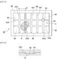
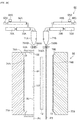
- FIG. 2 in the surfaces 69 and 71 of the resin core material 13 respectively opposing the two resin skin material sheets 12, lattice-shaped groove portions 93 are provided in the surfaces 69 and 71 of the resin core material 13 have the same structure. Accordingly, the groove portion 93 provided in one of the surfaces 69 will be described.
- the lattice-shaped groove portion 93 includes a first groove portion group extending in parallel to the long sides of the resin core material 13, and a second groove portion group extending in parallel to the short sides of the resin core material 13.
- the groove portion 93 seven groove portions 93A to 93G are provided.
- the groove portions 93A and 93B are provided in parallel to the long sides of the resin core material 13.
- the groove portions 93C to 93G are provided in parallel to the short sides of the resin core material 13.
- the ends do not extend to the peripheral edge portion 86 of the resin core material 13.
- the groove portions 93 do not communicate with the annular space 88. In this case, it is difficult to predict how many air accumulations A of what size will be formed where between the resin skin material sheet 12 and the resin core material 13.
- the groove portions 93 can communicate with the unexpectedly formed air accumulation A.
- the air accumulation A it becomes possible for the accumulated air to be accumulated in a depression 89 (which will be described later) via the groove portions 93, and then exhausted via the groove portions 93 out of an atmosphere release hole (which will be described later).
- the closed region indicated by hatching of an arbitrary shape indicates the air accumulation A the location of which is indefinite.
- the interval (lattice width) of the adjacent groove portions 93 may be determined from such viewpoint.
- the groove portions 93 have a flattened trapezoidal cross sectional shape.
- the shape makes it possible, as will be described later, for the air accumulated in the air accumulation A when the split mold blocks are clamped during the molding of the sandwich panel to accumulate in the depression 89 (which will be described later) via the groove portions 93, and to be exhausted out of the atmosphere release hole (which will be described later) via the groove portions 93.
- the width L, depth D, and inclination angle ⁇ of the groove portions 93 may be determined from such viewpoint. More specifically, as will be described later, the shape of the groove portions 93 is determined such that the groove portions 93 are formed as permanent grooves that are not eliminated when the split mold blocks are clamped during the molding of the sandwich panel.
- the skin material sheets 12 include a sheet formed from polypropylene, engineering plastics, olefin-based resin or the like. By ensuring an interval between the skin material sheets 12 provided on both sides of the resin core material 13, i.e., by ensuring a bulk (thickness) of the resin core material 13, stiffness of the sandwich panel 10 as a whole, in particular bending stiffness, can be ensured. From this viewpoint, for the skin material sheet 12, a material of which stiffness is higher than at least that of the resin core material 13 is required.
- the skin material sheets 12 constitute an upper wall and a lower wall of the sandwich panel 10.
- the terminal ends of the skin material sheet 12A and the skin material sheet 12B at the outer periphery of the sandwich panel 10 are welded and integrated via a pinch-off part to constitute a sidewall.
- gaps are formed (not illustrated). The gaps prevent deformation of the sandwich panel 10 by a difference in thermal contraction between the skin material sheets 12 and the resin core material 13 that have been molded.
- the skin material sheets 12 are formed from polyolefin (for example, polypropylene or high-density polyethylene) which is a homopolymer or a copolymer of olefins such as ethylene, propylene, butane, isoprene pentene, or methylpentene.
- polyolefin for example, polypropylene or high-density polyethylene
- the skin material sheets 12 are formed from polyolefin (for example, polypropylene or high-density polyethylene) which is a homopolymer or a copolymer of olefins such as ethylene, propylene, butane, isoprene pentene, or methylpentene.
- the MFR of the polyolefin at 230°C is not more than 3.0 g/10 min and preferably 0.3 to 1.5 g/10 min.
- the skin material sheets 12 are formed from amorphous resin, such as acrylonitrile-butadiene-styrene copolymer, polystyrene, high-impact polystyrene (HIPS resin), or acrylonitrile-styrene copolymer (AS resin).
- the MFR of the amorphous resin at 200°C (as measured according to JIS K-7210 at a test temperature of 200°C and with a test load of 2.16 kg) is 3.0 to 60 g/10 min and preferably 30 to 50 g/10 min.
- the melt tension of the amorphous resin at 230°C (indicating the tensile force measured by means of a melt tension tester manufactured by Toyo Seiki Seisaku-Sho, Ltd.
- a hydrogen-added styrene-based thermoplastic elastomer in a range of less than 30 wt% and preferably less than 15 wt% is added to the skin material sheet 12.
- the hydrogen-added styrene-based thermoplastic elastomer are styrene-ethylene-butylene-styrene block copolymer; styrene-ethylene-propylene-styrene block copolymer; hydrogenated styrene-butadiene rubber; and a mixture thereof.
- the styrene content is less than 30 wt% and preferably less than 20 wt%.
- the MFR at 230°C (as measured according to JIS K-7210 at a test temperature of 230°C and with a test load of 2.16 kg) is 1.0 to 10 g/10 min and preferably not more than 5.0 g/10 min and not less than 1.0 g/10 min.
- the skin material sheet 12 may include an additive agent as in the case of the resin core material 13.
- the additive agent are inorganic fillers such as silica, mica, talc, calcium carbonate, glass fiber, and carbon fiber; plasticizer; stabilizer; coloring agent; antistatic agent; flame retardant; and foaming agent.
- silica, mica, glass fiber or the like may be added by not more than 50 wt% and preferably 30 to 40 wt% with respect to the molding resin.
- the decorative material sheet 14 when provided on the surface of the skin material sheet 12, is a sheet configured to enhance exterior appearance and for decorative purpose, or to protect an object that comes into contact with the molded article (for example, in the case of the cargo floor board, baggage placed on the upper surface of the board).
- a fibrous skin-material sheet-like skin material or film-like skin material is used, for example.
- the fibrous skin material include synthetic fibers such as polyester, polypropylene, polyamide, polyurethane, acrylic, and vinylon; semisynthetic fibers such as acetate and rayon; recycled fibers such as viscose rayon and cuprammonium rayon; natural fibers such as cotton, linen, wool, and silk; and blend fibers thereof.
- the depression 89 is provided at an intersection of the groove portions 93.
- the depression 89 is disposed so as to communicate with two groove portions 93A and 93G.
- the depression 89 forms a cylindrical through-hole.
- the through-hole has openings formed in the respective surfaces of the resin core material 13, and extends inwardly so as to penetrate in the thickness direction.
- the inside of the depression 89 constitutes a void closed by the corresponding resin skin material sheets 12. Accordingly, whether the air accumulation A is formed in one or the other surface of the resin core material 13, the air existing there can be collected in the depression 89 via the groove portions 93.
- the area of the openings is set so as to ensure sufficient surface adhesion between the respective surfaces of the resin core material 13 and the corresponding resin skin material sheets 12. More specifically, excessive opening area is avoided so as not to lead to a lack of area of adhesion and to a resultant insufficient surface adhesion.
- the volume of the void is set to be sufficient that, when the respective surfaces of the resin core material 13 and the corresponding resin skin material sheets 12 are surface-to-surface adhered to each other in the hollow portion, an increase in the internal pressure in the void can be suppressed by the air guided to the depression 89 via the groove portions 93. More specifically, the volume of the void is set to be not too small, so as not to cause an increase in the internal pressure in the void.
- the volume of the void is determined by the size of the openings of the depression 89 and the thickness of the resin core material 13.
- the thickness of the resin core material 13 may be determined in accordance with the expected volume of the air accumulation A, and with respect to a required volume of the void that has been determined and a maximum allowable area of the openings that has been determined from the viewpoint of ensuring surface adhesion.
- the thickness of the resin core material 13 is determined in advance as a specification of the sandwich panel 10, the size of the openings of the depression 89 may be determined in accordance therewith.
- a plurality of depressions 89 may be provided at positions sufficiently spaced apart from each other, from the viewpoint of ensuring surface adhesion.
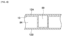
- the depressions 89 may be provided on the surface of the resin core material 13 on which the groove portions 93 are provided, instead of providing depressions 89 so as to penetrate in the thickness direction of the resin core material.
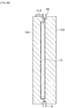
- the resin core material 13 may be deformed in the thickness direction, and the depressions 89 may be provided on one surface so as to protrude from the other surface (see FIG. 4 ).
- the atmosphere release hole 94 is provided, communicating with the groove portions 93 and penetrating in the sheet thickness direction.
- the diameter of the atmosphere release hole 94 is smaller than the width of the groove portions 93.
- the possible timing for providing the skin material sheet 12B with the atmosphere release hole 94 include the time before and after the surface-to-surface welding of the resin core material 13 and the skin material sheet 12B by the clamping of the split mold blocks, which will be described later.
- the atmosphere release hole 94 is formed in the skin material sheet 12B using a piercing needle, for example, before welding, formation of the air accumulation A during welding can be prevented.
- the atmosphere release hole 94 is formed by a similar method after welding, the air accumulation A that has been formed during welding may be processed later. In this case, if before welding, the atmosphere release hole 94 may be provided at an arbitrary position as long as communication with the groove portions 93 can be ensured. If after welding, the atmosphere release hole 94 may be provided at a position close to the depression 89.
- the peripheral edge portions 82 of the skin material sheets 12A and 12B may be welded so as to sandwich the foamed core material 13, using the foamed core material 13 that has already been molded.
- the sandwich panel 10 is molded, by joining the peripheral edge portions 82 of the front-side skin material sheet 12A and the back-side skin material sheet 12B, the hermetic space portion 84 is internally formed.
- the annular space 88 is actively formed between the peripheral edge portions 82 and the outer peripheral edge portion 86 of the foamed core material 13 in the hermetic space portion 84.
- the lattice-shaped groove portions 93 that are opened at the outer peripheral edge 86 of the resin core material 13 may be provided on the surfaces 69 and 71 of the resin core material 13 respectively opposing the two resin skin material sheets 12, the lattice-shaped groove portions 93 that are opened at the outer peripheral edge 86 of the resin core material 13 may be provided. Accordingly, the air accumulated in the air accumulation A is accumulated in the depression 89 via the groove portions 93. Moreover, the air is exhausted out of the atmosphere release hole 94 via the groove portions 93. Meanwhile, the groove portions 93 provided on the surface of the foamed core material 13 extend to the outer peripheral edge portion 86 of the foamed core material 13 so as to communicate with the annular space 88. In this way, during mold clamping, the air accumulation A, which may be formed between the foamed core material 13 and the skin material sheets 12A and 12B, can be dispersed to the annular space 88.
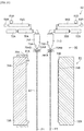
- a molding device 60 for the sandwich panel 10 includes extrusion devices 62, and a clamping device 64 disposed under the extrusion devices 62. Accordingly, molten parisons P extruded from the extrusion devices 62 are sent to the clamping device 64. The molten parisons P are then molded using the clamping device 64.
- the clamping device 64 as well as the extrusion devices 62 is of typically known types.
- the clamping device 64 includes two split-type molds 73 and a mold drive device. The mold drive device moves the molds 73 in a direction substantially perpendicular to the direction in which the molten sheet-like parisons P are supplied, between an open position and a closed position. Detailed description of the clamping device 64 is omitted.
- the two split-type molds 73 are disposed with their cavities 74 opposing each other.
- the molds 73 are disposed with their respective cavities 74 facing substantially the vertical direction.
- irregular portions in accordance with the outer shape and surface shape of the skin material sheets 12 that are to be molded based on the molten sheet-like parisons P are provided.
- the pinch-off part 76 is formed around the cavities 74.
- the pinch-off part 76 is formed around the cavities 74 in an annular shape while protruding toward the opposing molds 73. Accordingly, when the two split-type molds 73 are clamped, the apex portions of the respective pinch-off parts 76 abut against each other. As a result, a parting line PL is formed at the peripheral edge of the molten parisons P.
- a pair of frame members 75 is disposed in a nestled manner with respect to the pair of molds 73 and substantially in parallel with the cavities 74.
- the pair of frame members 75 each include an opening so that the pair of frame members 75 can be moved in the horizontal direction by a frame member drive device, which is not illustrated. Accordingly, the pair of frame members 75 can be moved in the opposite directions toward the corresponding molten parisons P, with the parisons P being retained, until the apexes of the pinch-off parts 76 of the corresponding molds 73 abut on the surfaces of the parisons P through the openings.
- the mold drive device may be a typical device.
- Each of the two split-type molds 73 is driven by the mold drive device. Accordingly, in the open position, the two molten sheet-like parisons P can be disposed between the two split mold blocks 73, at an interval therebetween.
- the pinch-off parts 76 of the two split mold blocks 73 abut on each other. In this way, as the annular pinch-off parts 76 abut on each other, a hermetic space is formed within the two split mold blocks 73.
- reference numeral 77 designates a ventilating contact plane
- reference numeral 78 designates a vacuum chamber
- reference numeral 79 designates a blow pin.
- the resin core material 13 is prepared and the decorative material 14 is disposed in the cavity 74B.
- foamed beads introduced in the mold may be fused and fixed by heating, as according to known art.
- the molding may be performed by blow molding, vacuum molding, press molding, or, in some cases, injection molding.
- the resin core material 13 may be of solid type obtained with a tubular parison, or of hollow type obtained with two strips of sheets, as long as the groove portions and the depression 89 communicating with the groove portions are formed in the respective surfaces.
- the resin core material 13 may be placed at any time between the opening of the molds and the clamping.
- thermoplastic resin sheets P1 and P2 are extruded out of the corresponding die slits vertically downward.
- two strips of continuous sheet-like thermoplastic resin sheets P1 and P2 are supplied between the two split mold blocks 73 in such a manner as to extend beyond the corresponding pinch-off parts 76.
- the frame 75A of the split mold block 73A is moved with respect to the split mold block 73A and toward the thermoplastic resin sheet P1.
- the frame 75A then abuts on a side surface 83 of the thermoplastic resin sheet P1.
- a hermetic space is formed by the side surface 83 of the thermoplastic resin sheet P1, the inner peripheral surface of the frame 75A, and the cavity 73A.
- thermoplastic resin sheet P1 is suction-attached to the cavity 74A.
- the thermoplastic resin sheet P1 is shaped in the shape in conformity to the surface of the cavity 74A.
- the resin core material 13 is disposed between the two strips of thermoplastic resin sheets P1 and P2, in parallel to both sheets.
- the surface of the resin core material 13 is then pressed onto the inner surface of the thermoplastic resin sheet P1, and welded and fixed.
- the opposite surface of the resin core material 13 is opened. Accordingly, the air between the resin core material 13 and the inner surface of the thermoplastic resin sheet P1 can be released via the lattice-shaped groove portions 93 and the depression 89.
- the atmosphere release hole is pierced in the sheet thickness direction using a piercing needle, for example, at a position corresponding to the flow passageway of the groove portions 93 of the thermoplastic resin sheet P1.
- the molds 73A and B are moved toward each other until the respective annular pinch-off parts 76A and 76B abut on each other, thereby performing clamping. More specifically, the pair of split mold blocks 73 is moved to the clamping position. Then, the inner surfaces of the two strips of thermoplastic resin sheets P1 and P2 are welded along the pinch-off parts 76 of the pair of molds 73.
- the peripheral edge portions of the two strips of thermoplastic resin sheets P1 and P2 are integrated, whereby the internal pressure of the molds 73 increases. Accordingly, the air in the air accumulation A formed somewhere between the inner surface of the resin skin material sheet P2 and the surface 69 of the resin core material 13 is accumulated in the depression 89 via the lattice-shaped groove portions 93. Moreover, the air is exhausted out of the atmosphere release hole 94 via the groove portions 93. Meanwhile, the resin core material 13 can be welded and integrated with the inner surfaces of the two strips of thermoplastic resin sheets P1 and P2. In this case, the decorative material 14 is also welded to the thermoplastic resin sheet P2.
- the extruded thermoplastic resin sheet P may be formed into the sheet form by crushing the molten tubular parison.
- the tubular parison may be formed into two sheets.
- the two split mold blocks 73 are opened, and the completed resin sandwich panel 10 is removed from the cavities 74. Burrs formed around the parting line PL are removed. Thus, the molding of the resin sandwich panel 10 is completed.
- thermoplastic resin sheets P1 and P2 are extruded intermittently.
- the extruded thermoplastic resin sheets P1 and P2 can be shaped into a predetermined shape, using the molds 73.
- each of the surfaces of the resin core material 13 opposing the two resin skin material sheets 12 is provided with the groove portions 93 extending across the entire surface, and the depression 89 communicating with the groove portions 93. Accordingly, when the surface of the resin core material 13 on the groove portions 93 side and the resin skin material sheet 12 opposing thereto are surface-to-surface adhered to each other, even if an unexpected air accumulation is formed therebetween, the air accumulated in the air accumulation can be accumulated in the depression 89 via the groove portions 93. Moreover, the air can be exhausted out of the atmosphere release hole 94 via the groove portions 93, the groove portions 93 serving an air-vent function.
- the resin sandwich panel 10 when the resin sandwich panel 10 is molded, for example, the risk of molding failure due to air accumulation can be eliminated. Even in the absence of molding failure, the risk of a lack of stiffness of the resin sandwich panel 10 as a whole due to the development of insufficient weld between the resin core material 13 and the resin skin material sheet can be eliminated. In addition, there is no risk of the aesthetic exterior appearance of the resin sandwich panel 10 being compromised by partial bulging of an air accumulation region that has expanded. Accordingly, the resin sandwich panel 10 can be provided in which molding failure is not caused and of which required stiffness can be ensured, while maintaining visual aesthetics of the panel.
- the second to the fourth embodiments of the present invention are characterized in that, as in the first embodiment, the skin material sheets 12 are provided with the atmosphere release hole 94 so as to communicate with the groove portions 93. Thereby, the air accumulated in the air accumulation accumulates in the depression 89 via the groove portions 93. In addition, in that way, there is likewise provided the air-vent function via the atmosphere release hole 94.
- the atmosphere release hole 94 is formed by piercing a piercing needle through the molten resin sheet constituting the skin material sheet 12 in the thickness direction thereof.
- the second to the fourth embodiments differ from each other in the position at which the atmosphere release hole 94 is provided with respect to the skin material sheet 12. The difference leads to different shapes of the groove portions 93 or different surface shapes of the core material 13.
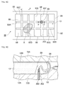
- the characterizing portions of the present embodiment lie in that the atmosphere release hole 94 is provided in the resin skin material sheet 12, and the corresponding form of the groove portions 93. More specifically, first, it is technically difficult to control the position of the piercing needle so that the apex of the piercing needle does not reach the surface of the resin core material 13 while forming, with the piercing needle, the atmosphere release hole 94 penetrating through the skin material sheet 12 in the thickness direction thereof. Accordingly, at the location of the resin core material 13 corresponding to the atmosphere release hole 94, a piercing needle avoidance space is provided. Specifically, as illustrated in FIG. 7 , the depression 89 is utilized as the piercing needle avoidance space.
- the size of the opening formed by the depression 89 is determined so as to ensure sufficient surface adhesion during the surface-to-surface welding of the resin core material 13 and the corresponding skin material sheet 12.
- the volume of the void portion formed by the depression 89 is determined from the viewpoint of suppressing an increase in the internal pressure in the void due to the air guided via the groove portions 93.
- the opening area required of the atmosphere release hole 94 is sufficient if ventilation is obtained between the void portion and the atmosphere. Accordingly, the opening area of the atmosphere release hole 94 is determined so that the depression 89 can be effectively utilized as the piercing needle avoidance space. The thickness of the piercing needle may be determined accordingly.
- the depth D and the inclination angle ⁇ of the groove portions 93 are set so that, as illustrated in FIG. 8 , when the split mold blocks are clamped, the groove portions 93 become crushed and, in addition, flattened. In this way, the back-side skin material sheet 12B is joined to the bottom surface 92 of the groove portions 93. Thereby, a sufficient joint between the back-side skin material sheet 12B and the resin core material 13 can be ensured.
- the groove portions 93 are additionally flattened by crushing the groove portions 93 of the resin core material 13. Then, the resin skin material sheet P2 is joined to the bottom surface 92 of the groove portion 90.
- the air accumulation A if the air accumulation A is formed at the position illustrated in FIG. 7 , for example, the air accumulation A will be in communication with any of the lattice-shaped groove portions 93. Accordingly, during the molding of the sandwich panel 10, the air can be vented from the air accumulation A via the groove portions 93 and through the atmosphere release hole 94. More specifically, during the clamping of the split mold blocks, the pressure in the hermetic space in the mold increases, so that the air accumulated in the air accumulation A can be released to the outer air out of the atmosphere release hole 94. In this case, it is difficult to predict how many air accumulations A of what size are formed where between the resin skin material sheet 12 and the resin core material 13.
- the present embodiment is similar to the first embodiment.
- the molding method for the sandwich panel 10 in the present embodiment is the same as that of the first embodiment.
- a third embodiment of the present invention will be described with reference to FIG. 9 .
- constituent elements similar to those of the first embodiment are designated with similar reference numerals, and their description is omitted.
- the characterizing portions of the present embodiment will be described in detail.
- the characterizing portions of the present embodiment differ from the second embodiment in the following respects.
- the atmosphere release hole 94 is provided at the location of the annular space 88 formed between the core material 13 and the skin material sheet 12. Accordingly, the groove portions 93 are disposed so as to be opened at the outer peripheral edge portion 86 of the core material 13, and communicate with the annular space 88.
- the resin core material 13 is surface-to-surface adhered to each of the skin material sheets 12 while being sandwiched between the skin material sheets 12.
- the annular space 88 per se serves as the air accumulation A.
- the volume is large compared with the air accumulation A on the resin core material 13. Accordingly, by actively utilizing the annular space 88 that has to be passively formed from the viewpoint of molding, the air accumulated over the resin core material 13 can be exhausted.
- the peripheral edge portions of the two resin skin material sheets 12 are joined. Accordingly, the annular space 88 is formed around the resin core material 13. At least one of the surfaces of the resin core material 13 opposing the two resin skin material sheets 12 is provided with the lattice-shaped groove portions 93 opened at the outer edge of the resin core material 13. Thereby, the lattice-shaped groove portions 93 communicate with the annular space 88.
- the lattice-shaped groove portions 93 provides an air-vent function.
- the resin sandwich panel 10 when the resin sandwich panel 10 is molded, the risk of molding failure due to the air accumulation A is eliminated. Or, even in the absence of molding failure, there is no risk of a lack of stiffness of the resin sandwich panel 10 as a whole due to the development of insufficient welding between the resin core material 13 and the resin skin material sheet 12. There is also no risk of the aesthetic exterior appearance of the resin sandwich panel 10 being damaged by partially bulging of the region of the air accumulation A that has expanded. Accordingly, the resin sandwich panel 10 can be provided in which molding failure is not caused and of which required stiffness can be ensured, while visual aesthetics of the panel is maintained.
- the present embodiment is characterized by the atmosphere release hole 94 provided at the portion of the skin material sheet 12 corresponding to the surface of the core material 13.
- the present embodiment is similar to the second embodiment.
- the atmosphere release hole 94 is provided in accordance with the position of the depression 89 provided on the surface of the core material 13, so that the depression 89 per se can be utilized as the piercing needle avoidance space.
- the atmosphere release hole 94 is provided at a position different from the position of the depression 89 provided the surface of the core material 13.
- the present embodiment is characterized in that the piercing needle avoidance space is provided in the surface of the core material 13 separately from the depression 89.
- the atmosphere release hole 94 is provided at a location of the skin material sheet 12 corresponding to an intersection of the groove portions 93. Accordingly, the piercing needle avoidance space 50 is provided at the intersection of the groove portions 93. Specifically, at the position of the resin core material 13 corresponding to the atmosphere release hole 94 of the skin material sheet 12, the avoidance space 50 is provided throughout along the thickness direction of the resin core material 13. The space has a size such that the piercing needle does not come into contact therewith.
- the avoidance space 50 has a cylindrical shape.
- the axis of the cylinder is perpendicular to the back-side skin material sheet 12B.
- the shape of the avoidance space 50 may be determined in accordance with the shape of the piercing needle. If the apex of the piercing needle reaches the surface of the resin core material 13, a hole may be formed in the surface of the resin core material 13. As a result, the resin core material 13 may be readily damaged.
- the shape of the piercing needle may be determined from the viewpoint of preventing this.
- the atmosphere release hole 94 may be provided in the skin material sheet 12 corresponding to the one surface. Accordingly, the avoidance space 50 need not penetrate through in the thickness direction of the resin core material 13.
- the avoidance space 50 may be provided as a recess opening on one surface.
- FIG. 12 a fifth embodiment of the present invention will be described with reference to FIG. 12 .
- constituent elements similar to those of the first embodiment will be designated with similar reference numerals, and their description is omitted.
- the characterizing portions of the present embodiment will be described in detail.
- the present embodiment is characterized by the shape of the groove portions 93.
- the present embodiment is similar to the first embodiment in that the groove portions 93 are permanent grooves. However, in the first embodiment, the groove portions 93 are lattice-shaped.
- a single curved long groove 100 is provided in a meandering manner across the entire surface of the resin core material 13.
- the present embodiment is characterized in this respect.
- the depression 89 is provided at the intersection of the groove portions 93. In the present embodiment, however, there is no intersection of the groove portions 93. Accordingly, the depression 89 is provided so as to communicate with the curved long groove 100 somewhere along the curved long groove 100.
- the groove portions 93 may have various shapes.
- a plurality of annular grooves 101 in the form of permanent grooves may be provided in a nestled manner.
- the adjacent annular grooves 101 communicate with each other via a communication passageway 103.
- the depression 89 may be provided somewhere along any of the nestled annular grooves 101.
- FIG. 14 and FIG. 15 a sixth embodiment of the present invention will be described with reference to FIG. 14 and FIG. 15 .
- constituent elements similar to those of the first embodiment will be designated with similar reference numerals, and their description is omitted.
- the characterizing portions of the present embodiment will be described.
- the surface of the core material 13 is provided with the depression 89.
- groove portions 93 communicating with the depression 89 are provided.
- the present embodiment is similar to the first embodiment.
- the present embodiment is characterized by the form of the depression 89 and the groove portions 93.
- the depression 89 is a cylindrical through-hole penetrating through the resin core material 13 in the thickness direction thereof.
- a piercing needle 202 is pierced from the outer surface of the resin sheet corresponding to the skin material sheet 12A at a location corresponding to the depression 89 toward the resin core material 13. In this way, the air accumulated in the depression 89 is released via the piercing needle 202.
- the diameter is set to be at least greater than the outer diameter of the piercing needle 202. In this way, the apex of the piercing needle 202 can penetrate through the skin material sheet 12A in the thickness direction thereof, and stay at a point along the thickness direction of the depression 89. In addition, no contact with the piercing needle 202 takes place.
- the piercing needle 202 has a hollow portion 203 extending to the apex thereof.
- the resin core material 13 and the opposing resin sheets are surface-to-surface welded.
- the pressure in the molds 73 increases.
- the air accumulated in the depression 89 is exhausted via the piercing needle 202.
- the groove portions 93 communicate with the annular space 88 formed between the peripheral edge portions 82 of the pair of skin material sheets 12 and the peripheral edge portion 86 of the resin core material 13.
- the present embodiment is similar to the first embodiment.
- the groove portions 93 are formed as permanent grooves. More specifically, the groove portions 93 are lattice-shaped so as to extend across the entire surface on each side of the resin core material 13.
- the depression 89 is provided at a lattice point.
- the depth and width of the groove portions 93, and the pitch between the adjacent groove portions 93 are determined in accordance with the use of the sandwich panel product 10. In particular, when a product overview is required, preferably the width may be narrowed and the depth may be made shallow.
- the width may be not more than 4 mm, and the depth may be not more than 1 mm.
- the groove portions 93 per se, as permanent grooves function as an active air accumulator similarly to the depression 89.
- the bulging portion 205 serves as a mark when the outer surface of the resin sheet is pierced by the piercing needle 202 toward the resin core material 13.
- FIG. 16 a seventh embodiment of the present invention will be described with reference to FIG. 16 .
- constituent elements similar to those of the first embodiment are designated with similar reference numerals, and their description is omitted.
- the characterizing portions of the present embodiment will be described.
- the surface of the resin core material 13 is provided with the depression 89.
- groove portions 93 communicating with the depression 89 are provided.
- the present embodiment is similar to the first embodiment.
- the present embodiment is characterized by the form of the depression 89 and the groove portions 93.
- the depression 89 is a substantially truncated conical shaped non-through-hole extending in the thickness direction of the resin core material 13.
- the depression 89 is provided near the peripheral edge portion 86 of the resin core material 13.
- a piercing needle 202 is pierced from the outer surface of the resin sheet corresponding to the skin material sheet 12A at a location corresponding to the depression 89 toward the resin core material 13. In this way, the air accumulated in the depression 89 is released via the piercing needle 202.
- the diameter is set to be at least greater than the outer diameter of the piercing needle 202. In this way, the apex of the piercing needle 202 can penetrate through the skin material sheet 12A in the thickness direction thereof, and stay at a point along the thickness direction of the depression 89. In addition, no contact with the piercing needle 202 takes place.
- the piercing needle 202 has a hollow portion 203 extending to the apex thereof.
- the resin core material 13 and the opposing resin sheets are surface-to-surface welded.
- the pressure in the molds 73 increases.
- the air accumulated in the depression 89 is exhausted via the piercing needle 202.
- the groove portions 93 communicate with the annular space 88 formed between the peripheral edge portions 82 of the pair of skin material sheets 12 and the peripheral edge portion 86 of the resin core material 13.
- the present embodiment is similar to the first embodiment.
- the groove portions 93 are formed as permanent grooves. More specifically, the groove portions 93 are provided, on one surface of the resin core material 13, as a single groove providing communication between the depression 89 provided near the peripheral edge portion 86 of the resin core material 13 and the annular space 88.
- the depth and width of the groove portions 93 are determined in accordance with the use of the sandwich panel product 10. In particular, when a product overview is required, preferably, the width may be made narrow and the depth may be made shallow. Preferably, for example, the width may be not more than 4 mm, and the depth may be not more than 1 mm.
- the air accumulated in the annular space 88 can be released to the depression 89 via the permanent grooves, and then exhausted via the piercing needle 202 pierced from the outer surface of the resin sheet corresponding to the skin material sheet 12A at the location corresponding to the depression 89.
- a sandwich panel 10 according to the present invention is a panel which may be preferably used as a structural member having high deflection stiffness or flexural buckling for uses including automobiles; aircraft; vehicles and ships; building materials; various electric device housings; floor boards for beds; and sports and leisure activities.
- the sandwich panel 10, as a structural member for automobiles and the like is a panel that helps to achieve an increase in fuel economy from the viewpoint of weight reduction.
- the sandwich panel 10 is a panel that contributes to weight reduction as an interior panel such as a cargo floor board, a deck board, a rear parcel shelf, a roof panel, or a door trim, and other structural members such as door inner panels, platforms, hardtops, sunroofs, hoods, bumpers, floor spacers, and tibia pads.
- the shape of the sandwich panel 10 may be appropriately determined in accordance with the purpose of the product.
- the present embodiment will be described with reference to a case where the sandwich panel 10 is used for an automobile cargo floor lid from which weight reduction and high stiffness are required.
- the sandwich panel 10 includes the front-side skin material sheet 12A, the back-side skin material sheet 12B, the foamable foamed core material 13 interposed between the skin material sheets 12A and 12B, and the decorative material sheet 14 affixed to the outer surface of the front-side skin material sheet 12A.
- the sandwich panel 10 is a laminated structural object including the decorative material sheet 14, the front-side skin material sheet 12A, the foamed core material 13, and the back-side skin material sheet 12B.
- the front-side skin material sheet 12A and the back-side skin material sheet 12B have the peripheral edge portions 82 thereof joined to each other, forming the internal hermetic space portion 84. Between the peripheral edge portions 82 and the outer peripheral edge portion 86 of the foamed core material 13 in the hermetic space portion 84, the annular space 88 is formed.
- the peripheral walls of the sandwich panel 10 are formed of the peripheral edge portions 82.
- the annular space 88 is provided passively from the viewpoint of preventing molding failure due to the peripheral walls becoming attached to the foamed core material 13.
- the sandwich panel 10 are molded by welding the peripheral edge portions 82 of the skin material sheets 12A and 12B so as to sandwich the foamed core material 13 that has already been molded, a groove portion which is provided on the surface of the foamed core material 13, as will be described later, can extend to the outer peripheral edge portion 86 of the foamed core material 13 and communicate with the annular space 88. In this way, during mold clamping, an air accumulation which may be formed between the foamed core material 13 and the skin material sheets 12A and 12B can be dispersed to the annular space 88.
- the lattice-shaped groove portions 93 are provided that are opened at the outer peripheral edge 91 of the resin core material 13.
- the groove portions 93 provided in the surfaces 69 and 71 of the resin core material 13 have the same structure. Accordingly, only the groove portions 93 provided on one surface 69 will be described.
- the lattice-shaped groove portions 93 are constituted by a first groove portion group extending in parallel to the long sides of the resin core material 13, and a second groove portion group extending in parallel to the short sides of the resin core material 13.
- the groove portions of the first groove portion group and the second groove portion group are provided so as to be opened at the outer peripheral edge 86 of the resin core material 13. More specifically, seven groove portions 93 of groove portions 93A to 93G are provided.
- the groove portions 93A and 93B are provided in parallel to the long sides of the resin core material 13.
- the groove portions 93C to G are provided in parallel to the short sides of the resin core material 13.
- the groove portions are all provided so as to be opened at the outer peripheral edge 86 of the resin core material 13. In this case, it is difficult to predict how many air accumulations A of what size are formed where between the resin skin material sheet 12 and the resin core material 13.
- the density of the lattice-shaped groove portions 93 increased so that the groove portions 93 can communicate with the unexpectedly formed air accumulation A.
- the accumulated air can be dispersed to the annular space 88.
- the closed region indicated by hatching of an arbitrary shape indicates the air accumulation A the location of which is indefinite.
- the interval (lattice width) of the adjacent groove portions 93 may be determined from such viewpoint.
- the groove portions 93 have a flattened trapezoidal cross sectional shape.
- the width L, depth D, and inclination angle ⁇ of the groove portions 93 may be determined from the viewpoint of dispersing the air accumulated in the air accumulation A via the groove portions 93 when the split mold blocks are clamped during the molding of the sandwich panel, as will be described later.
- FIG. 20(B) when the split mold blocks are clamped, the groove portions 93 are crushed and further flattened, as will be described later.
- the back-side skin material sheet 12B is joined to the bottom surface 92 of the groove portions 93, whereby a sufficient joint between the back-side skin material sheet 12B and the resin core material 13 is ensured.
- the depth D and the inclination angle ⁇ need to be determined from such viewpoint.
- a molding device 60 for the resin sandwich panel 10 includes an extrusion device 62 and a clamping device 64 disposed under the extrusion device 62. Accordingly, a molten thermoplastic resin sheet P extruded from the extrusion device 62 is sent to the clamping device 64. The molten thermoplastic resin sheet P is then molded by the clamping device 64.
- the extrusion devices 62 is of typical known type, and includes a cylinder 66 fitted with a hopper 65; a screw (not illustrated) provided in the cylinder 66; a hydraulic motor 68 linked to the screw; an accumulator 70 which internally communicates with the cylinder 66; and a plunger 72 provided in the accumulator 70.
- Resin pellets fed from the hopper 65 are melted and kneaded in the cylinder 66 as the screw is rotated by the hydraulic motor 68.
- Molten resin is transferred to an accumulator chamber. In the accumulator chamber, a certain quantity of molten resin is accumulated. The molten resin is sent toward a T die 71 by the driving of the plunger 72.
- thermoplastic resin sheet P is extruded in the form of a continuous sheet.
- the thermoplastic resin sheet P is then sent out downward while being pinch-pressed by a pair of rollers 79 disposed at an interval, and drooped between the split mold blocks 73. Accordingly, the sheet-like thermoplastic resin sheet P is disposed between the split mold blocks 73 in a tensioned state without wrinkles or slack.
- Detailed description of the extrusion devices 62 is omitted.
- the extruding capacity of the extrusion device 62 is appropriately selected depending on the size of the molded front-side skin material sheets 12A and back-side skin material sheet 12B, and from the viewpoint of preventing a draw-down of the thermoplastic resin sheet P. More specifically, from a practical viewpoint, the rate of resin extrusion from the die slit may be several hundred kg/h or more and more preferably 700 kg/h or more. From the viewpoint of preventing a draw-down of the thermoplastic resin sheet P, the step of extruding the thermoplastic resin sheet P is preferably made as short as possible. While depending on the type of resin and the MFR value, the extrusion step is generally completed within 40 seconds and preferably within 30 seconds. Accordingly, the extruded amount of the thermoplastic resin from the die slit per unit area and unit time may be not less than 50 kg/hour and cm 2 and more preferably not less than 60 kg/hour and cm 2 .
- the die slit 75 is disposed vertically downward.
- the thermoplastic resin sheet P extruded from the die slit 75 is sent vertically downwardly as is while drooping from the die slit 75.
- the width of the die slit variable the thickness of the continuous sheet-like thermoplastic resin sheet P can be modified.
- the clamping device 64 is also of typical known type as is the extrusion device 62, and includes two split-type molds 73 and a mold drive device.
- the mold drive device causes the molds 73 to move between open position and closed position in a direction substantially perpendicular to the supply direction of the molten sheet-like thermoplastic resin sheet P.
- Detailed description of the clamping device 64 is omitted.
- the two split-type molds 73 are disposed with the cavities 74 opposing each other.
- the molds 73 are respectively disposed with the cavities 74 facing substantially the vertical direction.
- the surface of each of the cavities 74 is provided with an irregular portion in accordance with the outer shape and surface shape of the front-side skin material sheet 12A and the back-side skin material sheet 12B, which are molded based on the molten sheet-like thermoplastic resin sheet P.
- the pinch-off part 76 is formed around the cavities 74.
- the pinch-off part 76 is formed around the cavities 74 in an annular shape while protruding toward the opposing molds 73. Accordingly, when the two split-type molds 73 are clamped, the apex portions of the respective pinch-off parts 76 abut against each other. As a result, a parting line PL is formed at the peripheral edge of the molten thermoplastic resin sheet P.
- the frame 81 A On the outer periphery portion of the split mold block 73A, the frame 81 A is slidably fitted. Accordingly, the frame 81A can be moved relative to the mold 73A by a frame moving device, which is not illustrated. More specifically, the frame 81A protrudes toward the mold 73B with respect to the mold 73A. Accordingly, the frame 81A can be abutted on one side surface 83 of the thermoplastic resin sheet P1 disposed between the molds 73.
- the split mold block 73A is internally provided with a vacuum suction chamber 85.
- the vacuum suction chamber 85 communicates with the cavity 74A via a suction hole 87.
- the thermoplastic resin sheet P1 is suction-attached toward the cavity 74A. In this way, a shape conforming to the shape of the outer surface of the cavity 74A is shaped.
- the mold drive device may be similar to a typical device, of which description is omitted.
- the two split-type molds 73 are respectively driven by the mold drive device. Accordingly, in the open position, two molten continuous sheet-like thermoplastic resin sheets P1 and P2 can be disposed at an interval between the two split mold blocks 73.
- the pinch-off parts 76 of the two split mold blocks 73 are abutted on each other. In this way, as the annular pinch-off parts 76 are abutted on each other, a hermetic space is formed within the two split mold blocks 73.
- the closed position is the position on the center line of the two strips of molten continuous sheet-like thermoplastic resin sheets P1 and P2. In this way, the molds 73 are driven by the mold drive device to move toward the closed position.
- the method for molding the foamed core material 13 may include a typical method by which foamed beads introduced into a mold are fused and fixed by heating. Alternatively, blow molding, vacuum molding, press molding, or, in some cases, injection molding, may also be used.
- the foamed core material 13 may be of solid type by a tubular parison or of hollow type by two strips of sheets. The foamed core material 13 may be placed at any time after mold opening and before clamping. Then, as illustrated in FIG.
- the molten thermoplastic resin sheets P1 and P2 are extruded from the corresponding die slit 75 vertically downward. In this way, the two strips of continuous sheet-like thermoplastic resin sheets P1 and P2 are supplied between the two split mold blocks 73 so as to extend beyond the corresponding pinch-off parts 76.
- the frame 81 A for the split mold block 73A is moved toward the thermoplastic resin sheet P1 relative to the split mold block 73A.
- the frame 81A then abuts on the side surface 83 of the thermoplastic resin sheet P1. Accordingly, a hermetic space 84 is formed by the side surface 83 of the thermoplastic resin sheet P1, the inner peripheral surface 102 of the frame 81 A, and the cavity 73A.
- thermoplastic resin sheet P1 is suction-attached to the cavity 74A, whereby the thermoplastic resin sheet P1 is shaped in the shape in conformity to the surface of the cavity 74A.
- the foamed core material 13 is disposed between the two strips of thermoplastic resin sheets P1 and P2, in parallel to both sheets.
- the surface of the foamed core material 13 is then pressed onto the inner surface of the thermoplastic resin sheet P1, and welded and fixed.
- the air between the foamed core material 13 and the inner surface of the thermoplastic resin sheet P1 can be released via the lattice-shaped groove portions 93.
- the molds 73A and B are moved toward each other until the respective annular pinch-off parts 76A and 76B abut on each other. Thereby, clamping is performed. More specifically, the pair of split mold blocks 73 are moved to the clamping position, and the inner surfaces of the two strips of thermoplastic resin sheets P1 and P2 are welded along the pinch-off parts of the pair of molds 73.
- the peripheral edge portions of the two strips of thermoplastic resin sheets P1 and P2 are integrated, whereby the internal pressure of the molds 73 increases. Accordingly, the air in the air accumulation A formed somewhere between the inner surface of the resin skin material sheet P2 and the surface 69 of the resin core material 13 can be dispersed to the annular space 88 via the lattice-shaped groove portions 93 and the peripheral edge portion 86 of the resin core material 13. Moreover, the resin core material 13 can be welded and integrated with the inner surfaces of the two strips of thermoplastic resin sheets P1 and P2. The decorative material 14 is also welded to the thermoplastic resin sheet P2. In this case, by crushing the groove portions 93 of the resin core material 13 (see FIG.
- the groove portions 93 are additionally flattened.
- the resin skin material sheet P2 is then joined to the bottom surface 92 of the groove portion 90. Thereby, a sufficient joint between the resin skin material sheet P2 and the resin core material 13 can be ensured.
- Such air-venting effect obtained during the clamping of the split mold blocks 73 is similarly obtained between the surface 71 of the resin core material 13 and the resin skin material sheet P1.
- the extruded thermoplastic resin sheet P may be formed in the sheet shape by crushing a molten tubular parison. During the extrusion of the molten tubular parison, the tubular parison may be cut at least at two locations along the extrusion direction, so as to form the tubular parison into two sheets.
- the two split mold block 73 are opened, and the completed resin sandwich panel 10 is removed from the cavities 74. Burrs formed around the parting line PL are removed. Thus, the molding of the resin sandwich panel 10 is completed.
- thermoplastic resin sheets P1 and P2 are extruded intermittently.
- the extruded thermoplastic resin sheets P1 and P2 can be shaped into a predetermined shape, using the molds 73.
- the resin core material 13 is surface-to-surface adhered to each of the skin material sheets 12 while being sandwiched between the skin material sheets 12.
- the annular space 88 per se constitutes an air accumulation.
- the weldability problem between the resin core material 13 and the skin material sheets 12 is eliminated.
- the problem of exterior appearance due to bulging is also small.
- the volume is large compared with the air accumulation on the resin core material 13. Accordingly, by actively utilizing the annular space 88 that has to be passively formed from the viewpoint of molding, the air accumulated over the resin core material 13 can be dispersed.
- the annular space 88 is formed around the resin core material 13. At least one of the surfaces of the resin core material 13 opposing the two resin skin material sheets 12 is provided with a lattice-shaped groove portion 93 opened at an outer edge of the resin core material 13. Thereby, the lattice-shaped groove portion 93 communicates with the annular space 88.
- the lattice-shaped groove portion 93 side and the resin skin material sheet 12 opposing thereto are surface-to-surface adhered to each other, even if an unexpected air accumulation is formed therebetween, the air accumulated in the air accumulation can be dispersed to the annular space 88 via the lattice-shaped groove portion 93.
- the annular space 88 per se constitutes an air accumulation.
- the weldability problem and the problem of exterior appearance due to bulging are small.
- the volume is large compared with the air accumulation on the resin core material. Accordingly, the lattice-shaped groove portion provides an air-vent function.
- the resin sandwich panel 10 when the resin sandwich panel 10 is molded, the risk of molding failure due to air accumulation A, or, even in the absence of molding failure, the risk of a lack of stiffness of the resin sandwich panel 10 as a whole due to insufficient welding of the resin core material 13 and the resin skin material sheet 12 is eliminated.
- the risk of the aesthetic exterior appearance of the resin sandwich panel 10 being compromised by a partial bulging of an air accumulation A region that has expanded is eliminated. Accordingly, the resin sandwich panel in which molding failure is not caused and of which required stiffness can be ensured can be provided while maintaining visual aesthetics.
- FIG. 26 to FIG. 27 a ninth embodiment of the present invention will be described with reference to FIG. 26 to FIG. 27 .
- constituent elements similar to those of the eighth embodiment will be designated with similar reference numerals, and their description is omitted.
- the characterizing portions of the present embodiment will be described in detail.
- the present embodiment is characterized in that the atmosphere release hole 90 is provided in the resin skin material sheet 12, and in the corresponding form of the groove portions 93. More specifically, as illustrated in FIG. 26 , the atmosphere release hole 90 provided in the resin skin material sheet 12 is a part of an adhered portion of the resin skin material sheet 12 with respect to the resin core material 13, i.e., a part of the resin skin material sheet 12 opposing the surface of the resin core material 13. Moreover, there is another atmosphere release hole 90 at a position corresponding to the annular space 88. In this way, two atmosphere release holes 90 are provided.
- the lattice-shaped groove portions 93 extend to the outer peripheral edge 86 of the resin core material 13 and are opened at the outer peripheral edge 86.
- the groove portions 93 are provided in a lattice shape.
- the present embodiment is similar to the eighth embodiment.
- the lattice-shaped groove portions 93 extend to the outer peripheral edge 86 of the resin core material 13 and are opened at the outer peripheral edge 86, while also extending to an inner peripheral edge 97 of the resin core material 13 and are opened at the inner peripheral edge 97.
- the present embodiment is characterized.
- a through-hole 99 is provided so as to communicate with the atmosphere release hole 90, while penetrating throughout the thickness of the resin core material 13.
- the groove portions 93 extend to the inner peripheral edge 97 of the through-hole 99, and are opened at the inner peripheral edge 97.
- the shape and size of the through-hole 99 may be arbitrary as long as the through-hole 99 communicates with the atmosphere release hole 90. However, from the viewpoint of ensuring the stiffness of the sandwich panel, preferably the shape is cylindrical and the size is made as small as possible.
- the air accumulation A communicates with any of the lattice-shaped groove portions 93. Accordingly, in the eighth embodiment, the accumulated air is dispersed to the annular space 88.
- air vent can be performed from the air accumulation A via the groove portions 93, and through the atmosphere release hole 90. More specifically, during the clamping of the split mold blocks, the pressure of the hermetic space in the mold increases. The air accumulated in the air accumulation A is released via the groove portions 93B, 93C, or A to the through-hole 99.
- the air can be further released to the outer air from the atmosphere release hole 90 that communicates with the through-hole 99, or from the atmosphere release hole 90 provided at the position corresponding to the annular space 88.
- the atmosphere release hole 90 that communicates with the through-hole 99, or from the atmosphere release hole 90 provided at the position corresponding to the annular space 88.
- the groove portions 93 communicate with the unexpectedly formed air accumulation A.
- the accumulated air can be released via the atmosphere release hole 90 no matter where the air accumulation A may be formed.
- the present embodiment is similar to the eighth embodiment.
- the method for molding the sandwich panel according to the present embodiment is similar to the one for the eighth embodiment.
- the present embodiment is characterized in that the depression 89 is further provided at an intersection of the groove portions 93.
- the depression 89 is provided at the intersection of the groove portions 93 as in the first embodiment.
- the depression 89 is disposed so as to communicate with the vertical and horizontal groove portions 93.
- the depression 89 forms a cylindrical through-hole, as in the first embodiment.
- the through-hole includes openings formed in the respective surfaces of the resin core material 13, and extends inwardly so as to penetrate in the thickness direction.
- the inside of the depression 89 constitutes a void closed by the corresponding resin skin material sheets 12.
- the air accumulated in the air accumulation A can be dispersed to the annular space 88 via the lattice-shaped groove portions 93. Moreover, the air can be collected to the depression 89 via the groove portions 93.
- the fifth embodiment has been described with reference to the case where, based on the first embodiment, the lattice-shaped groove portions 93 are provided as a single curved long groove, or as a plurality of annular grooves that are nestled.
- the embodiments of the present invention are not limited to such configuration.
- the lattice-shaped groove portions 93 may be provided as a single curved long groove or as a plurality of annular grooves that are nestled.
- the third embodiment has been described with reference to the case where all of the lattice-shaped groove portions 93 extend to the outer peripheral edge of the core material 13.
- the embodiments of the present invention are not limited thereto.
- the annular space 88 communicates with the air accumulation A via the groove portions 93, some may extend to the outer peripheral edge of the core material 13.
- the molten thermoplastic resin sheets P1 and P2 extruded from the extrusion slit are directly molded.
- the embodiments of the present invention are not limited thereto.
- One and/or the other of the thermoplastic resin sheets P1 and P2 may be preliminarily molded in advance, and later made into molten state by re-heating.
- the eighth embodiment has been described with reference to the case where the lattice-shaped groove portion is provided.
- the embodiments of the present invention are not limited thereto.
- the groove portion may be provided in the shape of a cross.
- the molten thermoplastic resin sheets P1 and P2 extruded from the extrusion slit are directly molded.
- the configuration is not a limitation, and one and/or the other of the thermoplastic resin sheets P1 and P2 may be preliminarily molded in advance, and later made into molten state by re-heating.
Landscapes
- Engineering & Computer Science (AREA)
- Mechanical Engineering (AREA)
- Laminated Bodies (AREA)
- Blow-Moulding Or Thermoforming Of Plastics Or The Like (AREA)
Abstract
Description
- The present invention relates to a resin sandwich panel. More specifically, the present invention relates to a resin sandwich panel in which molding failure is not caused and of which required stiffness can be ensured, while maintaining visual aesthetics.
- So-called sandwich panels have been typically used for various purposes, including transport machines such as automobiles and aircraft; building materials; floor boards for beds; electric device housings; and sports and leisure activities. A sandwich panel includes two skin material sheets and a core material interposed between the skin material sheets. A laminated structure of the skin material sheet, the core material, and the skin material sheet is the basic form. In accordance with the purpose, the functions required of the sandwich panel may vary. For example, when visual aesthetics are considered important while not much strength is required, such as in the case of an interior panel for use in the bathroom, a decorative material may be additionally affixed to the front-side skin material sheet presenting the exterior appearance. In this way, importance is given to the surface property of the decorative material or the overall molded shape. When the use is as structural material, strength is demanded more than visual aesthetics. In this respect, interior material components for transport machines such as automobiles and aircraft, particularly the cargo floor board, deck board, rear parcel shelf and the like for vehicles, are required to be lightweight from the viewpoint of increasing fuel economy, as well as being strong. Accordingly, resin sandwich panels including the skin material sheets and core material that are made of resin have often been used.
- More specifically, when a sandwich panel made of resin is utilized as an automobile cargo floor lid, the sandwich panel is used for the placement of heavy baggage on the cargo floor lid. Accordingly, the sandwich panel is required to have not just visual aesthetics but also the stiffness (particularly bending stiffness) to withstand the weight of the baggage. On the other hand, being lightweight is also demanded from the viewpoint of increasing fuel economy. Therefore, it is necessary to overcome the technical problem of achieving both high stiffness and lightweight, which is difficult to solve. Accordingly, as skin material sheets of the resin sandwich panels for such uses, hard resin material having a high Young's modulus has been adopted. Meanwhile, with regard to the core material, the bulk (core material thickness) may be increased so as to maximize the interval between the skin material sheets, so that the core material per se can be made lightweight while achieving an increase in section modulus. For this purpose, foamed material is adopted, for example. Alternatively, a core material with an internal hollow portion or a number of recesses in the surface thereof may be adopted.
- In such resin sandwich panel, in order to achieve weight reduction by providing the core material with voids, resin may be foamed to produce numerous internal cells, as disclosed in
Patent Document 1 and Patent Document 2.Patent Document 1 and Patent Document 2 commonly relate to the sandwich structural body for interior material panels of automobiles, such as deck boards and floor panels. According toPatent Document 1, two strips of molten parisons are positioned between split mold blocks. Between the two strips of molten parisons, apre-molded core material 13 made of resin, such as polypropylene, is disposed. Then, molding is performed by pressing the split mold blocks using vacuum or compressed air. According to Patent Document 2, with the split mold blocks disposed one above the other, a back-side sheet material that has been previously molded and then softened by re-heating is placed on the lower mold block. Then, the back-side sheet material is vacuum-suctioned via the lower mold block, whereby the back-side sheet material is shaped. A foamed resin of polyethylene, for example, is placed on the back-side sheet material, with a front-side sheet material that has been previously molded and then softened by re-heating placed on the foamed resin. Thereafter, the mold blocks are clamped while performing vacuum suction via the upper and lower mold blocks, whereby a sandwich structural body is molded. With the sandwich panel thus molded, weight reduction can be achieved by the formation of cells by foaming. - However, when the surface of the
resin core material 13 and the opposing thermoplastic resin sheet are welded, air is present therebetween. Accordingly, one or a plurality of air accumulations of various sizes may be formed at unexpected positions. As a result, the following technical problems may be caused. - First, molding failure or lack of stiffness may be caused in the resin sandwich panel. More specifically, unexpected air accumulations are formed between the surface of the
resin core material 13 and an opposing surface of the corresponding thermoplastic resin sheet. Accordingly, the air accumulations have a two-dimensional expanse. However, their thickness is very small, and their volume is also small. When the split mold blocks are clamped so as to sandwich theresin core material 13, the hermetic space inside the mold is pressurized. As a result, if there are air accumulations between the surface of theresin core material 13 and the opposing thermoplastic resin sheet, an internal pressure increase is readily caused by the clamping, resulting in bulging and an increase in the air accumulation region. This may cause peeling between the surface of theresin core material 13 and the opposing thermoplastic resin sheet. As a result, weld peel-off is readily caused, triggering a molding failure. Even when molding failure is not caused, insufficient welding may cause a decrease in stiffness of the resin sandwich panel as a whole. Secondly, the aesthetic exterior appearance of the resin sandwich panel may be lost. More specifically, if the air accumulation region expands as the split mold blocks are clamped as described above, portions of the outer surface of the thermoplastic resin sheet corresponding to the air accumulation region may partially bulge. As a result, the flatness of the outer surface of the thermoplastic resin sheet is lost, whereby the aesthetic exterior appearance of the resin sandwich panel is compromised. It is technically difficult to perform clamping of the split mold blocks while eliminating such air accumulations in advance. - Third, with the sandwich panel molding method, it may be difficult to obtain a high-quality sandwich panel. More specifically, for forming cells by foaming, as in
Patent Document 1 and Patent Document 2, chemical foaming technology or physical foaming technology is generally used. In either case, the foaming by itself does not pose a restriction on the core material molding method. As in the case of non-foamed core material, extrusion molding, injection molding, blow molding, or press molding may be utilized. However, as the foam expansion ratio is increased, it becomes difficult to adjust the foam expansion ratio, particularly in the case of extrusion molding or injection molding. As a result, it becomes difficult to obtain desired quality. - Patent Document 1:
JP-A-2006-334801 - Patent Document 2:
JP-A-2008-247003 - Patent Document 3:
JP-A-2010-52389 - In view of the above technical problems, an object of the present invention is to provide a resin sandwich panel in which molding failure is not caused and of which required stiffness can be ensured, while maintaining visual aesthetics.
- In order to achieve the above object, a resin sandwich panel according to the present invention includes: two resin skin material sheets; and a resin core material sandwiched between the skin material sheets and surface-to-surface adhered to each of the skin material sheets. The two resin skin material sheets have peripheral edge portions thereof joined to each other so as to form an internal hollow portion. The resin core material is disposed in the hollow portion. At least one of surfaces of the resin core material opposing the two resin skin material sheets has a groove portion extending across the entire surface, and a depression communicating with the groove portion. At least one of the two resin skin material sheets additionally has an atmosphere-opened through-hole provided in a thickness direction thereof so that when the at least one of the surfaces of the resin core material and the corresponding resin skin material sheet are surface-to-surface adhered to each other in the hollow portion, air between the at least one of the surfaces and the corresponding resin skin material sheet is guided to the depression via the groove portion, and exhausted out of the atmosphere-opened through-hole.
- According to the resin sandwich panel having the above-described configuration, at least one of the surfaces of the resin core material opposing the two resin skin material sheets is provided with a groove portion extending across the entire surface and a depression communicating with the groove portion. Accordingly, when the surface of the resin core material on the groove portion side and the resin skin material sheet opposing thereto are surface-to-surface adhered to each other, even if an unexpected air accumulation is formed therebetween, the air accumulated in the air accumulation can be accumulated in the depression via the groove portion. Moreover, the accumulated air can be exhausted from the atmosphere release hole via the groove portion. The groove portion provides the air-vent function. For example, when the resin sandwich panel is molded, the risk of molding failure due to air accumulation, or, even in the absence of molding failure, the risk of a lack of stiffness of the resin sandwich panel as a whole due to insufficient welding between the resin core material and the resin skin material sheet, is eliminated. In addition, the risk of the aesthetic exterior appearance of the resin sandwich panel being compromised by a partial bulging of an air accumulation region that has expanded is eliminated. Accordingly, the resin sandwich panel in which molding failure is not caused and of which required stiffness can be ensured can be provided while maintaining visual aesthetics. The depression herein refers to an internal space closed by the corresponding resin skin material sheet on at least one of the surfaces of the resin core material. The depression may or may not penetrate through the resin core material in the thickness direction thereof.
- The depression, moreover, includes an opening formed in the at least one of the surfaces, the depression extending inwardly and further including an internal void closed by the corresponding resin skin material sheet. The opening has an area set to ensure sufficient surface adhesion between the at least one of the surfaces and the corresponding resin skin material sheet. The void preferably has a volume set to be sufficient that, when the at least one of the surfaces of the resin core material and the corresponding resin skin material sheet are surface-to-surface adhered to each other in the hollow portion, an increase in an internal pressure of the void can be suppressed with the air guided to the depression via the groove portion.
- Additionally, the resin core material is in solid form. The depression is preferably constituted by the void formed in a solid portion.
- The resin core material, moreover, is constituted by a pair of thermoplastic resin plate members. The depression has an opening formed in a surface of one of the pair of thermoplastic resin plate members, and is constituted by an annular rib protruding, on an inner-surface side, toward the other thermoplastic resin plate member. The pair of thermoplastic resin plate members preferably forms an internal hollow portion.
- Additionally, the groove portion may include a single long curved groove.
- The groove portion may further include a plurality of nestled annular grooves, at least adjacent grooves of which communicating with each other.
- The groove portion, moreover, may be lattice-shaped and be constituted by a first groove portion group extending in parallel to a long side of the resin core material and a second groove portion group extending in parallel to a short side of the resin core material.
- The resin core material, moreover, is a foamed resin having a predetermined foam expansion ratio. The resin skin material sheet opposing the at least one of the surfaces of the resin core material may be joined to a bottom surface of the groove portion.
- The groove portion moreover, is disposed on each of the surfaces of the resin core material. The depression may be disposed penetrating through the resin core material in a thickness direction thereof.
- In addition, at least one of the two resin skin material sheets may be further provided with an atmosphere-opened through-hole communicating with the groove portion, in the thickness direction.
- The atmosphere-opened through-hole, moreover, is formed by piercing a piercing needle through at least one of the two resin skin material sheets. The depression is preferably provided on the at least one of the surfaces of the resin core material at a location corresponding to the atmosphere-opened through-hole so as to be sufficient to avoid interference with the piercing needle.
- Furthermore, the two resin skin material sheets have peripheral edge portions thereof joined to each other so as to form an outer peripheral space portion around the resin core material. The groove portion is provided so as to be opened at an outer edge of the resin core material, the groove portion thereby communicating with the outer peripheral space portion. The atmosphere-opened through-hole may be formed by piercing a piercing needle through at least one of the two resin skin material sheets at a position corresponding to the outer peripheral space portion.
- The atmosphere-opened through-hole, moreover, is formed by piercing a piercing needle through at least one of the two resin skin material sheets. The at least one of the surfaces of the resin core material may have a recess having a space sufficient to avoid interference with the piercing needle, the recess being provided at a location corresponding to the atmosphere-opened through-hole so as to communicate with the depression via the groove portion.
- The atmosphere-opened through-hole, moreover, is provided at a position corresponding to a flow passageway of the groove portion. The groove portion may be formed as a permanent groove that is not eliminated when the at least one of the surfaces of the resin core material and the corresponding resin skin material sheet are surface-to-surface adhered to each other.
- In addition, the two resin skin material sheets have peripheral edge portions thereof joined to each other so as to form an outer peripheral space portion around the resin core material. The groove portion may be formed in the shape of a lattice opened at an outer edge of the resin core material, the lattice-shaped groove portion thereby communicating with the outer peripheral space portion.
- In order to achieve the above object, a sandwich panel according to the present invention includes: two resin skin material sheets; and a resin core material sandwiched between the skin material sheets and surface-to-surface adhered to each of the skin material sheets. The two resin skin material sheets have peripheral edge portions thereof joined to each other so as to form an outer peripheral space portion around the resin core material. At least one of surfaces of the resin core material opposing the two resin skin material sheets has a lattice-shaped groove portion opened at an outer edge of the resin core material, the lattice-shaped groove portion thereby communicating with the outer peripheral space portion.
- In the resin sandwich panel having the above-described configuration, the resin core material is surface-to-surface adhered to each of the skin material sheets while being sandwiched between the skin material sheets. As the peripheral edge portions of the two resin skin material sheets are joined to each other, an outer peripheral space portion is formed around the resin core material. At least one of the surfaces of the resin core material opposing the two resin skin material sheets is provided with a lattice-shaped groove portion opened at an outer edge of the resin core material. Thereby, the lattice-shaped groove portion communicates with the outer peripheral space portion. Accordingly, when the surface of the resin core material on the lattice-shaped groove portion side and the resin skin material sheet opposing thereto are surface-to-surface adhered to each other, even if an unexpected air accumulation is formed therebetween, the air accumulated in the air accumulation can be dispersed to the outer peripheral space portion via the lattice-shaped groove portion. The outer peripheral space portion per se constitutes an air accumulation. However, compared with an air accumulation on the resin core material, the weldability problem and the problem of exterior appearance due to bulging are small. On the other hand, the volume is large compared with the air accumulation on the resin core material. Accordingly, the lattice-shaped groove portion provides an air-vent function. For example, when the resin sandwich panel is molded, the risk of molding failure due to air accumulation, or, even in the absence of molding failure, the risk of a lack of stiffness of the resin sandwich panel as a whole due to insufficient welding of the resin core material and the resin skin material sheet is eliminated. In addition, the risk of the aesthetic exterior appearance of the resin sandwich panel being compromised by a partial bulging of an air accumulation region that has expanded is eliminated. Accordingly, the resin sandwich panel in which molding failure is not caused and of which required stiffness can be ensured can be provided while maintaining visual aesthetics.
- Moreover, the outer peripheral space portion preferably constitutes a hermetic annular space portion.
- In addition, the resin core material is a foamed resin having a predetermined foam expansion ratio. At least one of the two resin skin material sheets may be joined to a bottom surface of the groove portion.
- Furthermore, the lattice-shaped groove portion may be disposed on a surface of the resin core material opposing each of the two resin skin material sheets.
- Furthermore, the lattice-shaped groove portion is constituted by a first groove portion group extending in parallel to a long side of the resin core material and a second groove portion group extending in parallel to a short side of the resin core material. The groove portions of the first groove portion group and the second groove portion group may be opened at an outer peripheral edge of the resin core material.
- Moreover, at least one of the two resin skin material sheets additionally preferably has an atmosphere-opened through-hole extending in a thickness direction thereof and communicating with the lattice-shaped groove portion.
- In addition, at least one of surfaces of the resin core material opposing the two resin skin material sheets has a depression communicating with the groove portion. The depression includes an opening formed in the at least one of the surfaces, the depression extending inwardly and further constituting an internal void closed by the corresponding resin skin material sheet. The opening has an area set to ensure sufficient surface adhesion between the at least one of the surfaces and the corresponding resin skin material sheet. The void may have a volume set to be sufficient that, when the at least one of the surfaces of the resin core material and the corresponding resin skin material sheet are surface-to-surface adhered to each other in the hollow portion, an increase in an internal pressure of the void can be suppressed by air guided to the depression via the groove portion so that when the at least one of the surfaces of the resin core material and the corresponding resin skin material sheet are surface-to-surface adhered to each other, air between the at least one of the surfaces and the corresponding resin skin material sheet is guided to the depression via the groove portion.
- In order to achieve the above object, a method for manufacturing a sandwich panel according to the present invention, the method including a resin core material sandwiched between two resin skin material sheets, includes: a step of preparing in advance the resin core material having a lattice-shaped groove portion formed in at least one of surfaces thereof, the lattice-shaped groove portion being opened at an outer edge of the resin core material; a step of arranging two strips of molten thermoplastic resin sheets between a pair of split-type molds so as to extend beyond an annular pinch-off part formed at a peripheral edge portion of a cavity of each of the pair of split-type molds; a step of forming a hermetic space between at least one of the molds and the corresponding thermoplastic resin sheet and suctioning the thermoplastic resin sheet by depressurizing the hermetic space so as to cause the thermoplastic resin sheet to follow the cavity for shaping; a step of causing the pair of split mold blocks to move to a clamping position so as to sandwich the resin core material between the two strips of molten thermoplastic resin sheets, and thereby welding inner surfaces of the two strips of thermoplastic resin sheets to each other along the pinch-off parts of the pair of split mold blocks, thus integrating the peripheral edge portions of the two strips of thermoplastic resin sheets and, in addition, forming an outer peripheral space portion around the resin core material, and surface-to-surface adhering the corresponding resin skin material sheet to the resin core material while performing air vent between the resin skin material sheet and the resin core material via the lattice-shaped groove portion.
- Moreover, the resin core material may be welded, before the clamping of the pair of split mold blocks, by being pressed onto an inner surface of the thermoplastic resin sheet molded by the suctioning.
- In addition, the one and/or the other thermoplastic resin sheet may be preliminarily molded in advance and turned into molten state by re-heating.
- Furthermore, the method may include a step of pushing out the one and the other molten thermoplastic resin sheets toward an area between the pair of split mold blocks so as to droop downward.
- Moreover, the thermoplastic resin sheets may be formed into sheet shape by crushing a molten tubular parison.
- In addition, the thermoplastic resin sheets may be formed into the two sheets by cutting a tubular parison at least at two locations thereof along an extrusion direction during extrusion of the molten tubular parison.
- Furthermore, the depressurizing step includes a step of causing an outer frame to be moved toward the corresponding outer surface of the thermoplastic resin sheet, the outer frame being fitted with respect to a peripheral edge of at least one of the split mold blocks so as to be freely movable in a clamp direction. The corresponding outer surface of the thermoplastic resin sheet, an inner peripheral surface of the outer frame, and a cavity of each of the pair of split mold blocks may constitute a hermetic space.
- Furthermore, the method may include a step of providing at least one of the two resin skin material sheets with an atmosphere-opened through-hole communicating with the lattice-shaped groove portion and extending in a thickness direction of the sheet.
- A first embodiment of a resin sandwich panel and a method for manufacturing the sandwich panel according to the present invention will be described with reference to the drawings.
- A
sandwich panel 10 according to the present invention is a panel which may be preferably used as a structural member having high deflection stiffness or flexural buckling for uses including automobiles; aircraft; vehicles and ships; building materials; various electric device housings; floor boards for beds; and sports and leisure activities. In particular, thesandwich panel 10, as a structural member for automobiles and the like, is a panel that helps to achieve an increase in fuel economy from the viewpoint of weight reduction. Specifically, thesandwich panel 10 is a panel that contributes to weight reduction as an interior panel such as a cargo floor board, a deck board, a rear parcel shelf, a roof panel, or a door trim, and other structural members such as door inner panels, platforms, hardtops, sunroofs, hoods, bumpers, floor spacers, and tibia pads. The shape of thesandwich panel 10 may be appropriately determined in accordance with the purpose of the product. - The present embodiment will be described with reference to the case where the
sandwich panel 10 is used for an automobile cargo floor lid from which weight reduction and high stiffness are required. - As illustrated in
FIG. 1 and FIG. 2 , thesandwich panel 10 includes a front-sideskin material sheet 12A, a back-sideskin material sheet 12B, a foamableresin core material 13 interposed between theskin material sheets decorative material sheet 14 affixed to an outer surface of the front-sideskin material sheet 12A. Thesandwich panel 10 is a laminated structural object including thedecorative material sheet 14, the front-sideskin material sheet 12A, theresin core material 13, and the back-sideskin material sheet 12B. - The front-side
skin material sheet 12A and the back-sideskin material sheet 12B haveperipheral edge portions 82 which are joined, forming an internalhermetic space portion 84. Between theperipheral edge portions 82 and an outerperipheral edge portion 86 of theresin core material 13 in thehermetic space portion 84, anannular space 88 is formed. When molten thermoplastic resin sheets as the materials of the front-sideskin material sheet 12A and the back-sideskin material sheet 12B are molded, peripheral walls of thesandwich panel 10 are formed by theperipheral edge portions 82. Theannular space 88 is provided passively from the viewpoint of preventing molding failure by the peripheral walls becoming attached to theresin core material 13. - The
resin core material 13 is formed from a resin with a foaming agent added thereto. Examples of the resin for forming theresin core material 13 include polyolefins (for example, polypropylene and high-density polyethylene), which are homopolymers or copolymers of olefins, such as ethylene, propylene, butane, isoprene pentene, and methylpentene; polyamide; polystyrene; polyvinyl chloride; acrylic derivatives such as polyacrylonitrile and ethylene-ethyl acrylate copolymer; polycarbonate; vinyl acetate copolymer such as ethylene-vinyl acetate copolymer; ionomer; terpolymers such as ethylene-propylene-diene terpolymers; acrylonitrile-styrene copolymer; ABS resin; polyphenylene oxide; polyacetal; phenol resin; polymethacrylimide; and polyetherimide. One kind of the above examples may be used independently, or two or more kinds may be used in a mixture. In particular, by using the same material for theresin core material 13 and theskin material sheet 12, the core material and the sheet can be adhered to each other by thermal welding, without using a solvent or the like. Theresin core material 13 may include an additive agent. Examples of the additive agent are inorganic fillers such as silica, mica, talc, calcium carbonate, glass fiber, and carbon fiber; plasticizer; stabilizer; coloring agent; antistatic agent; flame retardant; and foaming agent. - As the foaming agent that may be used for the present invention, any of a physical foaming agent, a chemical foaming agent, and a mixture thereof may be used. Examples of the physical foaming agent that may be used include inorganic system physical foaming agents such as air, carbonic acid gas, nitrogen gas, and water; organic system physical foaming agents such as butane, pentane, hexane, dichloromethane, and dichloroethane; and supercritical fluid thereof. The supercritical fluid may be preferably made using carbon dioxide or nitrogen, for example. In the case of nitrogen, a supercritical fluid can be obtained under the condition of a critical temperature of 149.1°C and a critical pressure of not less than 3.4 MPa. In the case of carbon dioxide, a supercritical fluid can be obtained under the condition of a critical temperature of 31°C and a critical pressure of not less than 7.4 MPa. As illustrated in
FIG. 2 , in thesurfaces resin core material 13 respectively opposing the two resinskin material sheets 12, lattice-shapedgroove portions 93 are provided. Thegroove portions 93 provided in thesurfaces resin core material 13 have the same structure. Accordingly, thegroove portion 93 provided in one of thesurfaces 69 will be described. As illustrated inFIG. 1 , the lattice-shapedgroove portion 93 includes a first groove portion group extending in parallel to the long sides of theresin core material 13, and a second groove portion group extending in parallel to the short sides of theresin core material 13. More specifically, as thegroove portion 93, sevengroove portions 93A to 93G are provided. Thegroove portions resin core material 13. On the other hand, thegroove portions 93C to 93G are provided in parallel to the short sides of theresin core material 13. Of each of thegroove portions 93A to 93G, the ends do not extend to theperipheral edge portion 86 of theresin core material 13. Thegroove portions 93 do not communicate with theannular space 88. In this case, it is difficult to predict how many air accumulations A of what size will be formed where between the resinskin material sheet 12 and theresin core material 13. Accordingly, it is necessary to increase the density of the lattice-shapedgroove portions 93 so that thegroove portions 93 can communicate with the unexpectedly formed air accumulation A. In this way, no matter where the air accumulation A may be formed, it becomes possible for the accumulated air to be accumulated in a depression 89 (which will be described later) via thegroove portions 93, and then exhausted via thegroove portions 93 out of an atmosphere release hole (which will be described later). InFIG. 1 , the closed region indicated by hatching of an arbitrary shape indicates the air accumulation A the location of which is indefinite. The interval (lattice width) of theadjacent groove portions 93 may be determined from such viewpoint. - As illustrated in
FIG. 3 , thegroove portions 93 have a flattened trapezoidal cross sectional shape. The shape makes it possible, as will be described later, for the air accumulated in the air accumulation A when the split mold blocks are clamped during the molding of the sandwich panel to accumulate in the depression 89 (which will be described later) via thegroove portions 93, and to be exhausted out of the atmosphere release hole (which will be described later) via thegroove portions 93. The width L, depth D, and inclination angle α of thegroove portions 93 may be determined from such viewpoint. More specifically, as will be described later, the shape of thegroove portions 93 is determined such that thegroove portions 93 are formed as permanent grooves that are not eliminated when the split mold blocks are clamped during the molding of the sandwich panel. - The
skin material sheets 12 include a sheet formed from polypropylene, engineering plastics, olefin-based resin or the like. By ensuring an interval between theskin material sheets 12 provided on both sides of theresin core material 13, i.e., by ensuring a bulk (thickness) of theresin core material 13, stiffness of thesandwich panel 10 as a whole, in particular bending stiffness, can be ensured. From this viewpoint, for theskin material sheet 12, a material of which stiffness is higher than at least that of theresin core material 13 is required. Theskin material sheets 12 constitute an upper wall and a lower wall of thesandwich panel 10. Preferably, the terminal ends of theskin material sheet 12A and theskin material sheet 12B at the outer periphery of thesandwich panel 10 are welded and integrated via a pinch-off part to constitute a sidewall. At the sidewall at the outer periphery of thesandwich panel 10 and at the outer periphery of theresin core material 13, gaps are formed (not illustrated). The gaps prevent deformation of thesandwich panel 10 by a difference in thermal contraction between theskin material sheets 12 and theresin core material 13 that have been molded. - More specifically, for the
skin material sheets 12, from the viewpoint of preventing thickness variations due to draw-down or neck-in, a resin material with a high melt tensile force is preferably used. On the other hand, for good transferability and tracking with respect to the mold, a resin material with high flowability is preferably used. Specifically, theskin material sheets 12 are formed from polyolefin (for example, polypropylene or high-density polyethylene) which is a homopolymer or a copolymer of olefins such as ethylene, propylene, butane, isoprene pentene, or methylpentene. The MFR of the polyolefin at 230°C (as measured according to JIS K-7210 at a test temperature of 230°C and with a test load of 2.16 kg) is not more than 3.0 g/10 min and preferably 0.3 to 1.5 g/10 min. Alternatively, theskin material sheets 12 are formed from amorphous resin, such as acrylonitrile-butadiene-styrene copolymer, polystyrene, high-impact polystyrene (HIPS resin), or acrylonitrile-styrene copolymer (AS resin). The MFR of the amorphous resin at 200°C (as measured according to JIS K-7210 at a test temperature of 200°C and with a test load of 2.16 kg) is 3.0 to 60 g/10 min and preferably 30 to 50 g/10 min. In addition, the melt tension of the amorphous resin at 230°C (indicating the tensile force measured by means of a melt tension tester manufactured by Toyo Seiki Seisaku-Sho, Ltd. when a strand being extruded out of an orifice with a diameter of 2.095 mm and a length of 8 mm at a remaining heat temperature of 230°C and at an extrusion rate of 5.7 mm/min is wound up on a roller with a diameter of 50 mm at a winding rate of 100 rpm) is not less than 50 mN and preferably not less than 120 mN. - Further, in order to prevent a shock-induced crack, a hydrogen-added styrene-based thermoplastic elastomer in a range of less than 30 wt% and preferably less than 15 wt% is added to the
skin material sheet 12. Specifically, preferable examples of the hydrogen-added styrene-based thermoplastic elastomer are styrene-ethylene-butylene-styrene block copolymer; styrene-ethylene-propylene-styrene block copolymer; hydrogenated styrene-butadiene rubber; and a mixture thereof. The styrene content is less than 30 wt% and preferably less than 20 wt%. The MFR at 230°C (as measured according to JIS K-7210 at a test temperature of 230°C and with a test load of 2.16 kg) is 1.0 to 10 g/10 min and preferably not more than 5.0 g/10 min and not less than 1.0 g/10 min. - In addition, the
skin material sheet 12 may include an additive agent as in the case of theresin core material 13. Examples of the additive agent are inorganic fillers such as silica, mica, talc, calcium carbonate, glass fiber, and carbon fiber; plasticizer; stabilizer; coloring agent; antistatic agent; flame retardant; and foaming agent. Specifically, silica, mica, glass fiber or the like may be added by not more than 50 wt% and preferably 30 to 40 wt% with respect to the molding resin. - The
decorative material sheet 14, when provided on the surface of theskin material sheet 12, is a sheet configured to enhance exterior appearance and for decorative purpose, or to protect an object that comes into contact with the molded article (for example, in the case of the cargo floor board, baggage placed on the upper surface of the board). As the material of thedecorative material sheet 14, a fibrous skin-material sheet-like skin material or film-like skin material is used, for example. Examples of the fibrous skin material include synthetic fibers such as polyester, polypropylene, polyamide, polyurethane, acrylic, and vinylon; semisynthetic fibers such as acetate and rayon; recycled fibers such as viscose rayon and cuprammonium rayon; natural fibers such as cotton, linen, wool, and silk; and blend fibers thereof. - Referring to
FIG. 1 and FIG. 3 , thedepression 89 will be described. Thedepression 89 is provided at an intersection of thegroove portions 93. Thedepression 89 is disposed so as to communicate with twogroove portions depression 89 forms a cylindrical through-hole. The through-hole has openings formed in the respective surfaces of theresin core material 13, and extends inwardly so as to penetrate in the thickness direction. The inside of thedepression 89 constitutes a void closed by the corresponding resinskin material sheets 12. Accordingly, whether the air accumulation A is formed in one or the other surface of theresin core material 13, the air existing there can be collected in thedepression 89 via thegroove portions 93. - The area of the openings is set so as to ensure sufficient surface adhesion between the respective surfaces of the
resin core material 13 and the corresponding resinskin material sheets 12. More specifically, excessive opening area is avoided so as not to lead to a lack of area of adhesion and to a resultant insufficient surface adhesion. Meanwhile, the volume of the void is set to be sufficient that, when the respective surfaces of theresin core material 13 and the corresponding resinskin material sheets 12 are surface-to-surface adhered to each other in the hollow portion, an increase in the internal pressure in the void can be suppressed by the air guided to thedepression 89 via thegroove portions 93. More specifically, the volume of the void is set to be not too small, so as not to cause an increase in the internal pressure in the void. In this respect, the volume of the void is determined by the size of the openings of thedepression 89 and the thickness of theresin core material 13. The thickness of theresin core material 13 may be determined in accordance with the expected volume of the air accumulation A, and with respect to a required volume of the void that has been determined and a maximum allowable area of the openings that has been determined from the viewpoint of ensuring surface adhesion. Alternatively, if the thickness of theresin core material 13 is determined in advance as a specification of thesandwich panel 10, the size of the openings of thedepression 89 may be determined in accordance therewith. If the size exceeds the maximum allowable area of the openings, a plurality ofdepressions 89 may be provided at positions sufficiently spaced apart from each other, from the viewpoint of ensuring surface adhesion. In a modification, if a plurality ofdepressions 89 is provided while thegroove portions 93 are provided in one of the surfaces of theresin core material 13, thedepressions 89 may be provided on the surface of theresin core material 13 on which thegroove portions 93 are provided, instead of providingdepressions 89 so as to penetrate in the thickness direction of the resin core material. In that case, not just when providing the non-through-holes in the solidresin core material 13, theresin core material 13 may be deformed in the thickness direction, and thedepressions 89 may be provided on one surface so as to protrude from the other surface (seeFIG. 4 ). As illustrated inFIG. 1 and FIG. 2 , in theskin material sheet 12B at a position corresponding to a flow passageway of thegroove portions 93, theatmosphere release hole 94 is provided, communicating with thegroove portions 93 and penetrating in the sheet thickness direction. The diameter of theatmosphere release hole 94 is smaller than the width of thegroove portions 93. The position of theatmosphere release hole 94, particularly its positional relationship with thedepression 89, may be determined from the following viewpoint. That is, the air that accumulates in the air accumulation A is accumulated in thedepression 89 via thegroove portions 93 and exhausted out of theatmosphere release hole 94. In this case, the possible timing for providing theskin material sheet 12B with theatmosphere release hole 94 include the time before and after the surface-to-surface welding of theresin core material 13 and theskin material sheet 12B by the clamping of the split mold blocks, which will be described later. When theatmosphere release hole 94 is formed in theskin material sheet 12B using a piercing needle, for example, before welding, formation of the air accumulation A during welding can be prevented. On the other hand, if theatmosphere release hole 94 is formed by a similar method after welding, the air accumulation A that has been formed during welding may be processed later. In this case, if before welding, theatmosphere release hole 94 may be provided at an arbitrary position as long as communication with thegroove portions 93 can be ensured. If after welding, theatmosphere release hole 94 may be provided at a position close to thedepression 89. - In a modification of the first embodiment, as illustrated in
FIG. 17 , theperipheral edge portions 82 of theskin material sheets core material 13, using the foamedcore material 13 that has already been molded. In this way, when thesandwich panel 10 is molded, by joining theperipheral edge portions 82 of the front-sideskin material sheet 12A and the back-sideskin material sheet 12B, thehermetic space portion 84 is internally formed. In addition, theannular space 88 is actively formed between theperipheral edge portions 82 and the outerperipheral edge portion 86 of the foamedcore material 13 in thehermetic space portion 84. Moreover, on thesurfaces resin core material 13 respectively opposing the two resinskin material sheets 12, the lattice-shapedgroove portions 93 that are opened at the outerperipheral edge 86 of theresin core material 13 may be provided. Accordingly, the air accumulated in the air accumulation A is accumulated in thedepression 89 via thegroove portions 93. Moreover, the air is exhausted out of theatmosphere release hole 94 via thegroove portions 93. Meanwhile, thegroove portions 93 provided on the surface of the foamedcore material 13 extend to the outerperipheral edge portion 86 of the foamedcore material 13 so as to communicate with theannular space 88. In this way, during mold clamping, the air accumulation A, which may be formed between the foamedcore material 13 and theskin material sheets annular space 88. - Next, as illustrated in
FIG. 5 , amolding device 60 for thesandwich panel 10 includesextrusion devices 62, and aclamping device 64 disposed under theextrusion devices 62. Accordingly, molten parisons P extruded from theextrusion devices 62 are sent to theclamping device 64. The molten parisons P are then molded using theclamping device 64. The clampingdevice 64 as well as theextrusion devices 62 is of typically known types. The clampingdevice 64 includes two split-type molds 73 and a mold drive device. The mold drive device moves themolds 73 in a direction substantially perpendicular to the direction in which the molten sheet-like parisons P are supplied, between an open position and a closed position. Detailed description of theclamping device 64 is omitted. - The two split-
type molds 73 are disposed with theircavities 74 opposing each other. Themolds 73 are disposed with theirrespective cavities 74 facing substantially the vertical direction. In the surfaces of therespective cavities 74, or more accurately, on the inside of an annular pinch-off part 76 which will be described later, irregular portions in accordance with the outer shape and surface shape of theskin material sheets 12 that are to be molded based on the molten sheet-like parisons P are provided. - In each of the two split-
type molds 73, the pinch-off part 76 is formed around thecavities 74. The pinch-off part 76 is formed around thecavities 74 in an annular shape while protruding toward the opposingmolds 73. Accordingly, when the two split-type molds 73 are clamped, the apex portions of the respective pinch-off parts 76 abut against each other. As a result, a parting line PL is formed at the peripheral edge of the molten parisons P. - Between the two split-
type molds 73, a pair offrame members 75 is disposed in a nestled manner with respect to the pair ofmolds 73 and substantially in parallel with thecavities 74. The pair offrame members 75 each include an opening so that the pair offrame members 75 can be moved in the horizontal direction by a frame member drive device, which is not illustrated. Accordingly, the pair offrame members 75 can be moved in the opposite directions toward the corresponding molten parisons P, with the parisons P being retained, until the apexes of the pinch-off parts 76 of the correspondingmolds 73 abut on the surfaces of the parisons P through the openings. - The mold drive device may be a typical device. Each of the two split-
type molds 73 is driven by the mold drive device. Accordingly, in the open position, the two molten sheet-like parisons P can be disposed between the two split mold blocks 73, at an interval therebetween. On the other hand, in the closed position, the pinch-off parts 76 of the two split mold blocks 73 abut on each other. In this way, as the annular pinch-off parts 76 abut on each other, a hermetic space is formed within the two split mold blocks 73. InFIG. 5 ,reference numeral 77 designates a ventilating contact plane;reference numeral 78 designates a vacuum chamber; andreference numeral 79 designates a blow pin. - A method for molding the
resin sandwich panel 10 using the above-described molding device will be described. In advance, theresin core material 13 is prepared and thedecorative material 14 is disposed in thecavity 74B. With regard to the molding method for theresin core material 13, foamed beads introduced in the mold may be fused and fixed by heating, as according to known art. Alternatively, the molding may be performed by blow molding, vacuum molding, press molding, or, in some cases, injection molding. Theresin core material 13 may be of solid type obtained with a tubular parison, or of hollow type obtained with two strips of sheets, as long as the groove portions and thedepression 89 communicating with the groove portions are formed in the respective surfaces. Theresin core material 13 may be placed at any time between the opening of the molds and the clamping. Thereafter, as illustrated inFIG. 5 , the molten thermoplastic resin sheets P1 and P2 are extruded out of the corresponding die slits vertically downward. In this way, two strips of continuous sheet-like thermoplastic resin sheets P1 and P2 are supplied between the two split mold blocks 73 in such a manner as to extend beyond the corresponding pinch-off parts 76. - Then, the
frame 75A of thesplit mold block 73A is moved with respect to thesplit mold block 73A and toward the thermoplastic resin sheet P1. Theframe 75A then abuts on aside surface 83 of the thermoplastic resin sheet P1. In this way, a hermetic space is formed by theside surface 83 of the thermoplastic resin sheet P1, the inner peripheral surface of theframe 75A, and thecavity 73A. - The air in the hermetic space is then suctioned out of the vacuum suction chamber via a suction hole, whereby the thermoplastic resin sheet P1 is suction-attached to the
cavity 74A. As a result, the thermoplastic resin sheet P1 is shaped in the shape in conformity to the surface of thecavity 74A. - Then, the
resin core material 13 is disposed between the two strips of thermoplastic resin sheets P1 and P2, in parallel to both sheets. The surface of theresin core material 13 is then pressed onto the inner surface of the thermoplastic resin sheet P1, and welded and fixed. In this case, the opposite surface of theresin core material 13 is opened. Accordingly, the air between theresin core material 13 and the inner surface of the thermoplastic resin sheet P1 can be released via the lattice-shapedgroove portions 93 and thedepression 89. Thereafter, the atmosphere release hole is pierced in the sheet thickness direction using a piercing needle, for example, at a position corresponding to the flow passageway of thegroove portions 93 of the thermoplastic resin sheet P1. - Then, as illustrated in
FIG. 6 , with theframe 75, abutting on theouter surface 83 of the thermoplastic resin sheet P1, being retained at the unchanged position, and with the thermoplastic resin sheet P1 being retained by suctioning, themolds 73A and B are moved toward each other until the respective annular pinch-off parts off parts 76 of the pair ofmolds 73. As a result, the peripheral edge portions of the two strips of thermoplastic resin sheets P1 and P2 are integrated, whereby the internal pressure of themolds 73 increases. Accordingly, the air in the air accumulation A formed somewhere between the inner surface of the resin skin material sheet P2 and thesurface 69 of theresin core material 13 is accumulated in thedepression 89 via the lattice-shapedgroove portions 93. Moreover, the air is exhausted out of theatmosphere release hole 94 via thegroove portions 93. Meanwhile, theresin core material 13 can be welded and integrated with the inner surfaces of the two strips of thermoplastic resin sheets P1 and P2. In this case, thedecorative material 14 is also welded to the thermoplastic resin sheet P2. The air-venting effect at the time of clamping of the split mold blocks 73 is similarly obtained between thesurface 71 of theresin core material 13 and the resin skin material sheet P1. It is noted that the extruded thermoplastic resin sheet P may be formed into the sheet form by crushing the molten tubular parison. In addition, during the extrusion of the molten tubular parison, by cutting the tubular parison at least at two locations along the extrusion direction, the tubular parison may be formed into two sheets. - Thereafter, the two split mold blocks 73 are opened, and the completed
resin sandwich panel 10 is removed from thecavities 74. Burrs formed around the parting line PL are removed. Thus, the molding of theresin sandwich panel 10 is completed. - As described above, each time the molten thermoplastic resin is intermittently extruded, the above steps are repeated. Accordingly, one
resin sandwich panel 10 after another can be efficiently molded. By the extrusion molding, the molten thermoplastic resin sheets P1 and P2 are extruded intermittently. The extruded thermoplastic resin sheets P1 and P2 can be shaped into a predetermined shape, using themolds 73. - In the
resin sandwich panel 10 with the above-described configuration, each of the surfaces of theresin core material 13 opposing the two resinskin material sheets 12 is provided with thegroove portions 93 extending across the entire surface, and thedepression 89 communicating with thegroove portions 93. Accordingly, when the surface of theresin core material 13 on thegroove portions 93 side and the resinskin material sheet 12 opposing thereto are surface-to-surface adhered to each other, even if an unexpected air accumulation is formed therebetween, the air accumulated in the air accumulation can be accumulated in thedepression 89 via thegroove portions 93. Moreover, the air can be exhausted out of theatmosphere release hole 94 via thegroove portions 93, thegroove portions 93 serving an air-vent function. Accordingly, when theresin sandwich panel 10 is molded, for example, the risk of molding failure due to air accumulation can be eliminated. Even in the absence of molding failure, the risk of a lack of stiffness of theresin sandwich panel 10 as a whole due to the development of insufficient weld between theresin core material 13 and the resin skin material sheet can be eliminated. In addition, there is no risk of the aesthetic exterior appearance of theresin sandwich panel 10 being compromised by partial bulging of an air accumulation region that has expanded. Accordingly, theresin sandwich panel 10 can be provided in which molding failure is not caused and of which required stiffness can be ensured, while maintaining visual aesthetics of the panel. - In the following, a second embodiment of the present invention will be described with reference to
FIG. 7 . In the following description, constituent elements similar to those of the first embodiment are designated with similar reference numerals, and their description is omitted. In the following, the characterizing portions of the present embodiment will be described. The second to the fourth embodiments of the present invention are characterized in that, as in the first embodiment, theskin material sheets 12 are provided with theatmosphere release hole 94 so as to communicate with thegroove portions 93. Thereby, the air accumulated in the air accumulation accumulates in thedepression 89 via thegroove portions 93. In addition, in that way, there is likewise provided the air-vent function via theatmosphere release hole 94. In addition, during the molding of thesandwich panel 10, theatmosphere release hole 94 is formed by piercing a piercing needle through the molten resin sheet constituting theskin material sheet 12 in the thickness direction thereof. However, the second to the fourth embodiments differ from each other in the position at which theatmosphere release hole 94 is provided with respect to theskin material sheet 12. The difference leads to different shapes of thegroove portions 93 or different surface shapes of thecore material 13. - The characterizing portions of the present embodiment lie in that the
atmosphere release hole 94 is provided in the resinskin material sheet 12, and the corresponding form of thegroove portions 93. More specifically, first, it is technically difficult to control the position of the piercing needle so that the apex of the piercing needle does not reach the surface of theresin core material 13 while forming, with the piercing needle, theatmosphere release hole 94 penetrating through theskin material sheet 12 in the thickness direction thereof. Accordingly, at the location of theresin core material 13 corresponding to theatmosphere release hole 94, a piercing needle avoidance space is provided. Specifically, as illustrated inFIG. 7 , thedepression 89 is utilized as the piercing needle avoidance space. In this case, as in the first embodiment, the size of the opening formed by thedepression 89 is determined so as to ensure sufficient surface adhesion during the surface-to-surface welding of theresin core material 13 and the correspondingskin material sheet 12. The volume of the void portion formed by thedepression 89 is determined from the viewpoint of suppressing an increase in the internal pressure in the void due to the air guided via thegroove portions 93. On the other hand, the opening area required of theatmosphere release hole 94 is sufficient if ventilation is obtained between the void portion and the atmosphere. Accordingly, the opening area of theatmosphere release hole 94 is determined so that thedepression 89 can be effectively utilized as the piercing needle avoidance space. The thickness of the piercing needle may be determined accordingly. Second, in particular, the depth D and the inclination angle α of thegroove portions 93 are set so that, as illustrated inFIG. 8 , when the split mold blocks are clamped, thegroove portions 93 become crushed and, in addition, flattened. In this way, the back-sideskin material sheet 12B is joined to thebottom surface 92 of thegroove portions 93. Thereby, a sufficient joint between the back-sideskin material sheet 12B and theresin core material 13 can be ensured. In this case, thegroove portions 93 are additionally flattened by crushing thegroove portions 93 of theresin core material 13. Then, the resin skin material sheet P2 is joined to thebottom surface 92 of thegroove portion 90. Thereby, a sufficient joint between the resin skin material sheet P2 and theresin core material 13 can be ensured. Moreover, during the surface-to-surface welding of the resin skin material sheet P2 and theresin core material 13, the air in the air accumulation A is guided to thedepression 89 and further to theatmosphere release hole 94 via thegroove portions 93. At the same time, the effect of forcing the air toward thedepression 89 by the crushing of thegroove portions 93 can be also expected. The adoption of thegroove portions 93 to be eliminated is common to the second to the fourth embodiments and the sixth embodiment. - By the above-described configuration, if the air accumulation A is formed at the position illustrated in
FIG. 7 , for example, the air accumulation A will be in communication with any of the lattice-shapedgroove portions 93. Accordingly, during the molding of thesandwich panel 10, the air can be vented from the air accumulation A via thegroove portions 93 and through theatmosphere release hole 94. More specifically, during the clamping of the split mold blocks, the pressure in the hermetic space in the mold increases, so that the air accumulated in the air accumulation A can be released to the outer air out of theatmosphere release hole 94. In this case, it is difficult to predict how many air accumulations A of what size are formed where between the resinskin material sheet 12 and theresin core material 13. Accordingly, it is necessary to have the density of the lattice-shapedgroove portions 93 on thesurface 69 increased. In this way, thegroove portions 93 can communicate with the unexpectedly formed air accumulation A, and the accumulated air can be released via theatmosphere release hole 94, no matter where the air accumulation A may be formed. In this respect, the present embodiment is similar to the first embodiment. The molding method for thesandwich panel 10 in the present embodiment is the same as that of the first embodiment. - In the following, a third embodiment of the present invention will be described with reference to
FIG. 9 . In the following description, constituent elements similar to those of the first embodiment are designated with similar reference numerals, and their description is omitted. In the following, the characterizing portions of the present embodiment will be described in detail. The characterizing portions of the present embodiment differ from the second embodiment in the following respects. Instead of theatmosphere release hole 94 being provided at the portion of theskin material sheet 12 corresponding to the surface of thecore material 13, theatmosphere release hole 94 is provided at the location of theannular space 88 formed between thecore material 13 and theskin material sheet 12. Accordingly, thegroove portions 93 are disposed so as to be opened at the outerperipheral edge portion 86 of thecore material 13, and communicate with theannular space 88. In theresin sandwich panel 10 having this configuration, theresin core material 13 is surface-to-surface adhered to each of theskin material sheets 12 while being sandwiched between theskin material sheets 12. For theresin core material 13, theannular space 88 per se serves as the air accumulation A. Compared with the air accumulation A formed on theresin core material 13, there is no problem of weldability between theresin core material 13 and theskin material sheets 12. The problem of exterior appearance due to bulging is also small. On the other hand, the volume is large compared with the air accumulation A on theresin core material 13. Accordingly, by actively utilizing theannular space 88 that has to be passively formed from the viewpoint of molding, the air accumulated over theresin core material 13 can be exhausted. - More specifically, the peripheral edge portions of the two resin
skin material sheets 12 are joined. Accordingly, theannular space 88 is formed around theresin core material 13. At least one of the surfaces of theresin core material 13 opposing the two resinskin material sheets 12 is provided with the lattice-shapedgroove portions 93 opened at the outer edge of theresin core material 13. Thereby, the lattice-shapedgroove portions 93 communicate with theannular space 88. Accordingly, when the surface of theresin core material 13 on the lattice-shapedgroove portions 93 side and the resinskin material sheet 12 opposing thereto are surface-to-surface adhered to each other, even if an unexpected air accumulation is formed therebetween, the air accumulated in the air accumulation can be dispersed to thedepression 89 and theannular space 88 via the lattice-shapedgroove portions 93. Theannular space 88 per se serves as the air accumulation A. Compared with the air accumulation A on theresin core material 13, the weldability problem and the problem of exterior appearance due to bulging are small. On the other hand, the volume is large compared with the air accumulation A on theresin core material 13. Accordingly, the lattice-shapedgroove portions 93 provides an air-vent function. For example, when theresin sandwich panel 10 is molded, the risk of molding failure due to the air accumulation A is eliminated. Or, even in the absence of molding failure, there is no risk of a lack of stiffness of theresin sandwich panel 10 as a whole due to the development of insufficient welding between theresin core material 13 and the resinskin material sheet 12. There is also no risk of the aesthetic exterior appearance of theresin sandwich panel 10 being damaged by partially bulging of the region of the air accumulation A that has expanded. Accordingly, theresin sandwich panel 10 can be provided in which molding failure is not caused and of which required stiffness can be ensured, while visual aesthetics of the panel is maintained. - In the following, a fourth embodiment of the present invention will be described with reference to
FIG. 10 to FIG. 11 . In the following description, constituent elements similar to those of the first embodiment will be designated with similar reference numerals, and their description is omitted. In the following, the characterizing portions of the present embodiment will be described. The present embodiment is characterized by theatmosphere release hole 94 provided at the portion of theskin material sheet 12 corresponding to the surface of thecore material 13. In this respect, the present embodiment is similar to the second embodiment. However, in the second embodiment, theatmosphere release hole 94 is provided in accordance with the position of thedepression 89 provided on the surface of thecore material 13, so that thedepression 89 per se can be utilized as the piercing needle avoidance space. In the present embodiment, however, theatmosphere release hole 94 is provided at a position different from the position of thedepression 89 provided the surface of thecore material 13. Thereby, the present embodiment is characterized in that the piercing needle avoidance space is provided in the surface of thecore material 13 separately from thedepression 89. - More specifically, as illustrated in
FIG. 10 , theatmosphere release hole 94 is provided at a location of theskin material sheet 12 corresponding to an intersection of thegroove portions 93. Accordingly, the piercingneedle avoidance space 50 is provided at the intersection of thegroove portions 93. Specifically, at the position of theresin core material 13 corresponding to theatmosphere release hole 94 of theskin material sheet 12, theavoidance space 50 is provided throughout along the thickness direction of theresin core material 13. The space has a size such that the piercing needle does not come into contact therewith. - More specifically, as illustrated in
FIG. 11 , theavoidance space 50 has a cylindrical shape. The axis of the cylinder is perpendicular to the back-sideskin material sheet 12B. The shape of theavoidance space 50 may be determined in accordance with the shape of the piercing needle. If the apex of the piercing needle reaches the surface of theresin core material 13, a hole may be formed in the surface of theresin core material 13. As a result, theresin core material 13 may be readily damaged. The shape of the piercing needle may be determined from the viewpoint of preventing this. In a modification where thegroove portions 93 are only provided on one of the surfaces of theresin core material 13, theatmosphere release hole 94 may be provided in theskin material sheet 12 corresponding to the one surface. Accordingly, theavoidance space 50 need not penetrate through in the thickness direction of theresin core material 13. Theavoidance space 50 may be provided as a recess opening on one surface. - In the following, a fifth embodiment of the present invention will be described with reference to
FIG. 12 . In the following description, constituent elements similar to those of the first embodiment will be designated with similar reference numerals, and their description is omitted. In the following, the characterizing portions of the present embodiment will be described in detail. - The present embodiment is characterized by the shape of the
groove portions 93. The present embodiment is similar to the first embodiment in that thegroove portions 93 are permanent grooves. However, in the first embodiment, thegroove portions 93 are lattice-shaped. In the present embodiment, a single curvedlong groove 100 is provided in a meandering manner across the entire surface of theresin core material 13. The present embodiment is characterized in this respect. In this case, in the first embodiment, thedepression 89 is provided at the intersection of thegroove portions 93. In the present embodiment, however, there is no intersection of thegroove portions 93. Accordingly, thedepression 89 is provided so as to communicate with the curvedlong groove 100 somewhere along the curvedlong groove 100. As long as thegroove portions 93 are provided across the entire surface of theresin core material 13, thegroove portions 93 may have various shapes. In a modification, as illustrated inFIG. 13 , a plurality of annular grooves 101 in the form of permanent grooves may be provided in a nestled manner. The adjacent annular grooves 101 communicate with each other via a communication passageway 103. In this case, thedepression 89 may be provided somewhere along any of the nestled annular grooves 101. - In the following, a sixth embodiment of the present invention will be described with reference to
FIG. 14 andFIG. 15 . In the following description, constituent elements similar to those of the first embodiment will be designated with similar reference numerals, and their description is omitted. In the following, the characterizing portions of the present embodiment will be described. - In the present embodiment, in order to release air from the unexpected air accumulation A formed between the surface of the
resin core material 13 and theskin material sheets core material 13 is provided with thedepression 89. Moreover,groove portions 93 communicating with thedepression 89 are provided. In this respect, the present embodiment is similar to the first embodiment. However, the present embodiment is characterized by the form of thedepression 89 and thegroove portions 93. As illustrated inFIG. 14 andFIG. 15 , thedepression 89 is a cylindrical through-hole penetrating through theresin core material 13 in the thickness direction thereof. During the molding, a piercingneedle 202 is pierced from the outer surface of the resin sheet corresponding to theskin material sheet 12A at a location corresponding to thedepression 89 toward theresin core material 13. In this way, the air accumulated in thedepression 89 is released via the piercingneedle 202. For this purpose, the diameter is set to be at least greater than the outer diameter of the piercingneedle 202. In this way, the apex of the piercingneedle 202 can penetrate through theskin material sheet 12A in the thickness direction thereof, and stay at a point along the thickness direction of thedepression 89. In addition, no contact with the piercingneedle 202 takes place. The piercingneedle 202 has ahollow portion 203 extending to the apex thereof. When themolds 73 are clamped during molding, theresin core material 13 and the opposing resin sheets are surface-to-surface welded. At the same time, the pressure in themolds 73 increases. In this case, by piercing the piercingneedle 202 immediately after the mold clamping, the air accumulated in thedepression 89 is exhausted via the piercingneedle 202. Alternatively, it is also possible to exhaust the air via the atmosphere release hole formed in theskin material sheet 12A communicating with thedepression 89, by removing the piercingneedle 202 that has been pierced. - The
groove portions 93 communicate with theannular space 88 formed between theperipheral edge portions 82 of the pair ofskin material sheets 12 and theperipheral edge portion 86 of theresin core material 13. In this respect, the present embodiment is similar to the first embodiment. However, thegroove portions 93 are formed as permanent grooves. More specifically, thegroove portions 93 are lattice-shaped so as to extend across the entire surface on each side of theresin core material 13. Thedepression 89 is provided at a lattice point. The depth and width of thegroove portions 93, and the pitch between theadjacent groove portions 93 are determined in accordance with the use of thesandwich panel product 10. In particular, when a product overview is required, preferably the width may be narrowed and the depth may be made shallow. For example, preferably the width may be not more than 4 mm, and the depth may be not more than 1 mm. In this way, as opposed to the first embodiment, the effect of the air being forced into thedepression 89 via thegroove portions 93 as thegroove portions 93 are eliminated during the clamping of themolds 73 cannot be obtained. On the other hand, thegroove portions 93 per se, as permanent grooves, function as an active air accumulator similarly to thedepression 89. - As illustrated in
FIG. 14 , by further increasing the diameter of the ends of the depression 89 (204A and 204B), the risk of the apex of the piercingneedle 202 as it is pierced coming into contact with thedepression 89 and thereby scratching theresin core material 13 is decreased. At the same time, the volume of thedepression 89 is increased, whereby its function as an active temporary air accumulator can be fully exploited. In addition, inFIG. 14 , as illustrated at the lower end of thedepression 89, an inwardly bulgingportion 205 is provided in the corresponding resin sheet so as to be accommodated within an increaseddiameter portion 204B at the lower end of thedepression 89. In this way, the bulgingportion 205 serves as a mark when the outer surface of the resin sheet is pierced by the piercingneedle 202 toward theresin core material 13. By the above-described configuration, during the molding, the air in the unexpected air accumulation A can be released to thedepression 89 via the permanent grooves and theannular space 88 or directly to thedepression 89 via the permanent grooves, and then exhausted via the piercingneedle 202 pierced from the outer surface of the resin sheet corresponding to theskin material sheet 12A at the location corresponding to thedepression 89. - In the following, a seventh embodiment of the present invention will be described with reference to
FIG. 16 . In the following description, constituent elements similar to those of the first embodiment are designated with similar reference numerals, and their description is omitted. In the following, the characterizing portions of the present embodiment will be described. - In the present embodiment, in order to release air from the unexpected air accumulation A formed between the surface of the
resin core material 13 and theskin material sheet 12 at the time of molding, the surface of theresin core material 13 is provided with thedepression 89. Moreover,groove portions 93 communicating with thedepression 89 are provided. In this respect, the present embodiment is similar to the first embodiment. However, the present embodiment is characterized by the form of thedepression 89 and thegroove portions 93. As illustrated inFIG. 14 andFIG. 15 , thedepression 89 is a substantially truncated conical shaped non-through-hole extending in the thickness direction of theresin core material 13. Thedepression 89 is provided near theperipheral edge portion 86 of theresin core material 13. During the molding, a piercingneedle 202 is pierced from the outer surface of the resin sheet corresponding to theskin material sheet 12A at a location corresponding to thedepression 89 toward theresin core material 13. In this way, the air accumulated in thedepression 89 is released via the piercingneedle 202. For this purpose, the diameter is set to be at least greater than the outer diameter of the piercingneedle 202. In this way, the apex of the piercingneedle 202 can penetrate through theskin material sheet 12A in the thickness direction thereof, and stay at a point along the thickness direction of thedepression 89. In addition, no contact with the piercingneedle 202 takes place. The piercingneedle 202 has ahollow portion 203 extending to the apex thereof. When themolds 73 are clamped during molding, theresin core material 13 and the opposing resin sheets are surface-to-surface welded. At the same time, the pressure in themolds 73 increases. In this case, by piercing the piercingneedle 202 immediately after the mold clamping, the air accumulated in thedepression 89 is exhausted via the piercingneedle 202. Alternatively, it is also possible to exhaust the air via the atmosphere release hole formed in theskin material sheet 12A communicating with thedepression 89, by removing the piercingneedle 202 that has been pierced. - The
groove portions 93 communicate with theannular space 88 formed between theperipheral edge portions 82 of the pair ofskin material sheets 12 and theperipheral edge portion 86 of theresin core material 13. In this respect, the present embodiment is similar to the first embodiment. However, thegroove portions 93 are formed as permanent grooves. More specifically, thegroove portions 93 are provided, on one surface of theresin core material 13, as a single groove providing communication between thedepression 89 provided near theperipheral edge portion 86 of theresin core material 13 and theannular space 88. The depth and width of thegroove portions 93 are determined in accordance with the use of thesandwich panel product 10. In particular, when a product overview is required, preferably, the width may be made narrow and the depth may be made shallow. Preferably, for example, the width may be not more than 4 mm, and the depth may be not more than 1 mm. - By the above-described configuration, by utilizing the
annular space 88 as an active air accumulator during the molding, the air accumulated in theannular space 88 can be released to thedepression 89 via the permanent grooves, and then exhausted via the piercingneedle 202 pierced from the outer surface of the resin sheet corresponding to theskin material sheet 12A at the location corresponding to thedepression 89. - In the following, the eighth embodiment of the resin sandwich panel according to the present invention and a method for manufacturing the sandwich panel will be described with reference to the drawings.
- A
sandwich panel 10 according to the present invention is a panel which may be preferably used as a structural member having high deflection stiffness or flexural buckling for uses including automobiles; aircraft; vehicles and ships; building materials; various electric device housings; floor boards for beds; and sports and leisure activities. In particular, thesandwich panel 10, as a structural member for automobiles and the like, is a panel that helps to achieve an increase in fuel economy from the viewpoint of weight reduction. Specifically, thesandwich panel 10 is a panel that contributes to weight reduction as an interior panel such as a cargo floor board, a deck board, a rear parcel shelf, a roof panel, or a door trim, and other structural members such as door inner panels, platforms, hardtops, sunroofs, hoods, bumpers, floor spacers, and tibia pads. The shape of thesandwich panel 10 may be appropriately determined in accordance with the purpose of the product. - The present embodiment will be described with reference to a case where the
sandwich panel 10 is used for an automobile cargo floor lid from which weight reduction and high stiffness are required. - As illustrated in
FIG. 18 , thesandwich panel 10 includes the front-sideskin material sheet 12A, the back-sideskin material sheet 12B, the foamable foamedcore material 13 interposed between theskin material sheets decorative material sheet 14 affixed to the outer surface of the front-sideskin material sheet 12A. Thesandwich panel 10 is a laminated structural object including thedecorative material sheet 14, the front-sideskin material sheet 12A, the foamedcore material 13, and the back-sideskin material sheet 12B. - As illustrated in
FIG. 18 andFIG. 19 , the front-sideskin material sheet 12A and the back-sideskin material sheet 12B have theperipheral edge portions 82 thereof joined to each other, forming the internalhermetic space portion 84. Between theperipheral edge portions 82 and the outerperipheral edge portion 86 of the foamedcore material 13 in thehermetic space portion 84, theannular space 88 is formed. When molten thermoplastic resin sheets as the material of the front-sideskin material sheet 12A and the back-sideskin material sheet 12B are molded, the peripheral walls of thesandwich panel 10 are formed of theperipheral edge portions 82. Theannular space 88 is provided passively from the viewpoint of preventing molding failure due to the peripheral walls becoming attached to the foamedcore material 13. In this way, when, as will be described later, thesandwich panel 10 are molded by welding theperipheral edge portions 82 of theskin material sheets core material 13 that has already been molded, a groove portion which is provided on the surface of the foamedcore material 13, as will be described later, can extend to the outerperipheral edge portion 86 of the foamedcore material 13 and communicate with theannular space 88. In this way, during mold clamping, an air accumulation which may be formed between the foamedcore material 13 and theskin material sheets annular space 88. - As illustrated in
FIG. 19 , in thesurfaces resin core material 13 respectively opposing the two resinskin material sheets 12, the lattice-shapedgroove portions 93 are provided that are opened at the outer peripheral edge 91 of theresin core material 13. Thegroove portions 93 provided in thesurfaces resin core material 13 have the same structure. Accordingly, only thegroove portions 93 provided on onesurface 69 will be described. The lattice-shapedgroove portions 93 are constituted by a first groove portion group extending in parallel to the long sides of theresin core material 13, and a second groove portion group extending in parallel to the short sides of theresin core material 13. The groove portions of the first groove portion group and the second groove portion group are provided so as to be opened at the outerperipheral edge 86 of theresin core material 13. More specifically, sevengroove portions 93 ofgroove portions 93A to 93G are provided. Thegroove portions resin core material 13. Thegroove portions 93C to G are provided in parallel to the short sides of theresin core material 13. The groove portions are all provided so as to be opened at the outerperipheral edge 86 of theresin core material 13. In this case, it is difficult to predict how many air accumulations A of what size are formed where between the resinskin material sheet 12 and theresin core material 13. Accordingly, it is necessary to have the density of the lattice-shapedgroove portions 93 increased so that thegroove portions 93 can communicate with the unexpectedly formed air accumulation A. In this way, no matter where the air accumulation A may be formed, the accumulated air can be dispersed to theannular space 88. InFIG. 19 , the closed region indicated by hatching of an arbitrary shape indicates the air accumulation A the location of which is indefinite. The interval (lattice width) of theadjacent groove portions 93 may be determined from such viewpoint. - As illustrated in
FIG. 20 , thegroove portions 93 have a flattened trapezoidal cross sectional shape. The width L, depth D, and inclination angle α of thegroove portions 93 may be determined from the viewpoint of dispersing the air accumulated in the air accumulation A via thegroove portions 93 when the split mold blocks are clamped during the molding of the sandwich panel, as will be described later. As illustrated inFIG. 20(B) , when the split mold blocks are clamped, thegroove portions 93 are crushed and further flattened, as will be described later. As a result, the back-sideskin material sheet 12B is joined to thebottom surface 92 of thegroove portions 93, whereby a sufficient joint between the back-sideskin material sheet 12B and theresin core material 13 is ensured. In particular, the depth D and the inclination angle α need to be determined from such viewpoint. - A device and method for molding the
resin sandwich panel 10 having the above-described configuration using a mold will be described. As illustrated inFIG. 21 , amolding device 60 for theresin sandwich panel 10 includes anextrusion device 62 and aclamping device 64 disposed under theextrusion device 62. Accordingly, a molten thermoplastic resin sheet P extruded from theextrusion device 62 is sent to theclamping device 64. The molten thermoplastic resin sheet P is then molded by the clampingdevice 64. - The
extrusion devices 62 is of typical known type, and includes a cylinder 66 fitted with a hopper 65; a screw (not illustrated) provided in the cylinder 66; a hydraulic motor 68 linked to the screw; an accumulator 70 which internally communicates with the cylinder 66; and a plunger 72 provided in the accumulator 70. Resin pellets fed from the hopper 65 are melted and kneaded in the cylinder 66 as the screw is rotated by the hydraulic motor 68. Molten resin is transferred to an accumulator chamber. In the accumulator chamber, a certain quantity of molten resin is accumulated. The molten resin is sent toward a T die 71 by the driving of the plunger 72. Through a die slit (not illustrated), a thermoplastic resin sheet P is extruded in the form of a continuous sheet. The thermoplastic resin sheet P is then sent out downward while being pinch-pressed by a pair ofrollers 79 disposed at an interval, and drooped between the split mold blocks 73. Accordingly, the sheet-like thermoplastic resin sheet P is disposed between the split mold blocks 73 in a tensioned state without wrinkles or slack. Detailed description of theextrusion devices 62 is omitted. - The extruding capacity of the
extrusion device 62 is appropriately selected depending on the size of the molded front-sideskin material sheets 12A and back-sideskin material sheet 12B, and from the viewpoint of preventing a draw-down of the thermoplastic resin sheet P. More specifically, from a practical viewpoint, the rate of resin extrusion from the die slit may be several hundred kg/h or more and more preferably 700 kg/h or more. From the viewpoint of preventing a draw-down of the thermoplastic resin sheet P, the step of extruding the thermoplastic resin sheet P is preferably made as short as possible. While depending on the type of resin and the MFR value, the extrusion step is generally completed within 40 seconds and preferably within 30 seconds. Accordingly, the extruded amount of the thermoplastic resin from the die slit per unit area and unit time may be not less than 50 kg/hour and cm2 and more preferably not less than 60 kg/hour and cm2. - The die slit 75 is disposed vertically downward. Thus, the thermoplastic resin sheet P extruded from the die slit 75 is sent vertically downwardly as is while drooping from the die slit 75. By making the width of the die slit variable, the thickness of the continuous sheet-like thermoplastic resin sheet P can be modified.
- Meanwhile, the clamping
device 64 is also of typical known type as is theextrusion device 62, and includes two split-type molds 73 and a mold drive device. The mold drive device causes themolds 73 to move between open position and closed position in a direction substantially perpendicular to the supply direction of the molten sheet-like thermoplastic resin sheet P. Detailed description of theclamping device 64 is omitted. - The two split-
type molds 73 are disposed with thecavities 74 opposing each other. Themolds 73 are respectively disposed with thecavities 74 facing substantially the vertical direction. The surface of each of thecavities 74 is provided with an irregular portion in accordance with the outer shape and surface shape of the front-sideskin material sheet 12A and the back-sideskin material sheet 12B, which are molded based on the molten sheet-like thermoplastic resin sheet P. - In each of the two split-
type molds 73, the pinch-off part 76 is formed around thecavities 74. The pinch-off part 76 is formed around thecavities 74 in an annular shape while protruding toward the opposingmolds 73. Accordingly, when the two split-type molds 73 are clamped, the apex portions of the respective pinch-off parts 76 abut against each other. As a result, a parting line PL is formed at the peripheral edge of the molten thermoplastic resin sheet P. - On the outer periphery portion of the
split mold block 73A, theframe 81 A is slidably fitted. Accordingly, theframe 81A can be moved relative to themold 73A by a frame moving device, which is not illustrated. More specifically, theframe 81A protrudes toward themold 73B with respect to themold 73A. Accordingly, theframe 81A can be abutted on oneside surface 83 of the thermoplastic resin sheet P1 disposed between themolds 73. - As illustrated in
FIG. 22 , thesplit mold block 73A is internally provided with avacuum suction chamber 85. Thevacuum suction chamber 85 communicates with thecavity 74A via asuction hole 87. By performing suctioning from thevacuum suction chamber 85 via thesuction hole 87, the thermoplastic resin sheet P1 is suction-attached toward thecavity 74A. In this way, a shape conforming to the shape of the outer surface of thecavity 74A is shaped. - The mold drive device may be similar to a typical device, of which description is omitted. The two split-
type molds 73 are respectively driven by the mold drive device. Accordingly, in the open position, two molten continuous sheet-like thermoplastic resin sheets P1 and P2 can be disposed at an interval between the two split mold blocks 73. On the other hand, in the closed position, the pinch-off parts 76 of the two split mold blocks 73 are abutted on each other. In this way, as the annular pinch-off parts 76 are abutted on each other, a hermetic space is formed within the two split mold blocks 73. With regard to the movement of themolds 73 from the open position to the closed position, the closed position is the position on the center line of the two strips of molten continuous sheet-like thermoplastic resin sheets P1 and P2. In this way, themolds 73 are driven by the mold drive device to move toward the closed position. - A method for molding the
resin sandwich panel 10 using the above-described molding device will be described. In advance, the foamedcore material 13 is prepared, and thedecorative material 14 is placed in thecavity 74B. The method for molding the foamedcore material 13 may include a typical method by which foamed beads introduced into a mold are fused and fixed by heating. Alternatively, blow molding, vacuum molding, press molding, or, in some cases, injection molding, may also be used. The foamedcore material 13 may be of solid type by a tubular parison or of hollow type by two strips of sheets. The foamedcore material 13 may be placed at any time after mold opening and before clamping. Then, as illustrated inFIG. 21 , the molten thermoplastic resin sheets P1 and P2 are extruded from the corresponding die slit 75 vertically downward. In this way, the two strips of continuous sheet-like thermoplastic resin sheets P1 and P2 are supplied between the two split mold blocks 73 so as to extend beyond the corresponding pinch-off parts 76. - Then, as illustrated in
FIG. 23 , theframe 81 A for thesplit mold block 73A is moved toward the thermoplastic resin sheet P1 relative to thesplit mold block 73A. Theframe 81A then abuts on theside surface 83 of the thermoplastic resin sheet P1. Accordingly, ahermetic space 84 is formed by theside surface 83 of the thermoplastic resin sheet P1, the innerperipheral surface 102 of theframe 81 A, and thecavity 73A. - Then, as illustrated in
FIG. 22 , the air in thehermetic space 84 is suctioned from thevacuum suction chamber 85 via thesuction hole 87. Accordingly, the thermoplastic resin sheet P1 is suction-attached to thecavity 74A, whereby the thermoplastic resin sheet P1 is shaped in the shape in conformity to the surface of thecavity 74A. - Then, the foamed
core material 13 is disposed between the two strips of thermoplastic resin sheets P1 and P2, in parallel to both sheets. The surface of the foamedcore material 13 is then pressed onto the inner surface of the thermoplastic resin sheet P1, and welded and fixed. In this case, the air between the foamedcore material 13 and the inner surface of the thermoplastic resin sheet P1 can be released via the lattice-shapedgroove portions 93. - Then, as illustrated in
FIG. 24 , with the frame 81 abutting on theouter surface 83 of the thermoplastic resin sheet P1 being retained at the unchanged position, and with the thermoplastic resin sheet P1 being retained by suctioning, themolds 73A and B are moved toward each other until the respective annular pinch-off parts molds 73. Accordingly, the peripheral edge portions of the two strips of thermoplastic resin sheets P1 and P2 are integrated, whereby the internal pressure of themolds 73 increases. Accordingly, the air in the air accumulation A formed somewhere between the inner surface of the resin skin material sheet P2 and thesurface 69 of theresin core material 13 can be dispersed to theannular space 88 via the lattice-shapedgroove portions 93 and theperipheral edge portion 86 of theresin core material 13. Moreover, theresin core material 13 can be welded and integrated with the inner surfaces of the two strips of thermoplastic resin sheets P1 and P2. Thedecorative material 14 is also welded to the thermoplastic resin sheet P2. In this case, by crushing thegroove portions 93 of the resin core material 13 (seeFIG. 20(B) ), thegroove portions 93 are additionally flattened. The resin skin material sheet P2 is then joined to thebottom surface 92 of thegroove portion 90. Thereby, a sufficient joint between the resin skin material sheet P2 and theresin core material 13 can be ensured. Such air-venting effect obtained during the clamping of the split mold blocks 73 is similarly obtained between thesurface 71 of theresin core material 13 and the resin skin material sheet P1. The extruded thermoplastic resin sheet P may be formed in the sheet shape by crushing a molten tubular parison. During the extrusion of the molten tubular parison, the tubular parison may be cut at least at two locations along the extrusion direction, so as to form the tubular parison into two sheets. - Then, as illustrated in
FIG. 25 , the two splitmold block 73 are opened, and the completedresin sandwich panel 10 is removed from thecavities 74. Burrs formed around the parting line PL are removed. Thus, the molding of theresin sandwich panel 10 is completed. - As described above, each time the molten thermoplastic resin is intermittently extruded, the above steps are repeated. Accordingly, one
resin sandwich panel 10 after another can be efficiently molded. By the extrusion molding, the molten thermoplastic resin sheets P1 and P2 are extruded intermittently. The extruded thermoplastic resin sheets P1 and P2 can be shaped into a predetermined shape, using themolds 73. - In the
resin sandwich panel 10 having the above-described configuration, theresin core material 13 is surface-to-surface adhered to each of theskin material sheets 12 while being sandwiched between theskin material sheets 12. In theresin core material 13, theannular space 88 per se constitutes an air accumulation. However, compared with an air accumulation formed on theresin core material 13, the weldability problem between theresin core material 13 and theskin material sheets 12 is eliminated. The problem of exterior appearance due to bulging is also small. On the other hand, the volume is large compared with the air accumulation on theresin core material 13. Accordingly, by actively utilizing theannular space 88 that has to be passively formed from the viewpoint of molding, the air accumulated over theresin core material 13 can be dispersed. - More specifically, as the peripheral edge portions of the two resin
skin material sheets 12 are joined to each other, theannular space 88 is formed around theresin core material 13. At least one of the surfaces of theresin core material 13 opposing the two resinskin material sheets 12 is provided with a lattice-shapedgroove portion 93 opened at an outer edge of theresin core material 13. Thereby, the lattice-shapedgroove portion 93 communicates with theannular space 88. Accordingly, when the surface of theresin core material 13 on the lattice-shapedgroove portion 93 side and the resinskin material sheet 12 opposing thereto are surface-to-surface adhered to each other, even if an unexpected air accumulation is formed therebetween, the air accumulated in the air accumulation can be dispersed to theannular space 88 via the lattice-shapedgroove portion 93. Theannular space 88 per se constitutes an air accumulation. However, compared with an air accumulation on theresin core material 13, the weldability problem and the problem of exterior appearance due to bulging are small. On the other hand, the volume is large compared with the air accumulation on the resin core material. Accordingly, the lattice-shaped groove portion provides an air-vent function. For example, when theresin sandwich panel 10 is molded, the risk of molding failure due to air accumulation A, or, even in the absence of molding failure, the risk of a lack of stiffness of theresin sandwich panel 10 as a whole due to insufficient welding of theresin core material 13 and the resinskin material sheet 12 is eliminated. In addition, the risk of the aesthetic exterior appearance of theresin sandwich panel 10 being compromised by a partial bulging of an air accumulation A region that has expanded is eliminated. Accordingly, the resin sandwich panel in which molding failure is not caused and of which required stiffness can be ensured can be provided while maintaining visual aesthetics. - In the following, a ninth embodiment of the present invention will be described with reference to
FIG. 26 to FIG. 27 . In the following description, constituent elements similar to those of the eighth embodiment will be designated with similar reference numerals, and their description is omitted. In the following, the characterizing portions of the present embodiment will be described in detail. - The present embodiment is characterized in that the
atmosphere release hole 90 is provided in the resinskin material sheet 12, and in the corresponding form of thegroove portions 93. More specifically, as illustrated inFIG. 26 , theatmosphere release hole 90 provided in the resinskin material sheet 12 is a part of an adhered portion of the resinskin material sheet 12 with respect to theresin core material 13, i.e., a part of the resinskin material sheet 12 opposing the surface of theresin core material 13. Moreover, there is anotheratmosphere release hole 90 at a position corresponding to theannular space 88. In this way, two atmosphere release holes 90 are provided. Meanwhile, with regard to the form of thegroove portions 93, in the eighth embodiment, the lattice-shapedgroove portions 93 extend to the outerperipheral edge 86 of theresin core material 13 and are opened at the outerperipheral edge 86. On the other hand, in the present embodiment, as illustrated inFIG. 9 , thegroove portions 93 are provided in a lattice shape. In this respect, the present embodiment is similar to the eighth embodiment. However, in the ninth embodiment, the lattice-shapedgroove portions 93 extend to the outerperipheral edge 86 of theresin core material 13 and are opened at the outerperipheral edge 86, while also extending to an innerperipheral edge 97 of theresin core material 13 and are opened at the innerperipheral edge 97. In this respect, the present embodiment is characterized. - More specifically, as illustrated in
FIG. 27 , at the position of theresin core material 13 corresponding to theatmosphere release hole 90, a through-hole 99 is provided so as to communicate with theatmosphere release hole 90, while penetrating throughout the thickness of theresin core material 13. Thegroove portions 93 extend to the innerperipheral edge 97 of the through-hole 99, and are opened at the innerperipheral edge 97. The shape and size of the through-hole 99 may be arbitrary as long as the through-hole 99 communicates with theatmosphere release hole 90. However, from the viewpoint of ensuring the stiffness of the sandwich panel, preferably the shape is cylindrical and the size is made as small as possible. - According to the above-described configuration, if, for example, the air accumulation A is formed at the position illustrated in
FIG. 26 , the air accumulation A communicates with any of the lattice-shapedgroove portions 93. Accordingly, in the eighth embodiment, the accumulated air is dispersed to theannular space 88. However, in the present embodiment, during the molding of the sandwich panel, air vent can be performed from the air accumulation A via thegroove portions 93, and through theatmosphere release hole 90. More specifically, during the clamping of the split mold blocks, the pressure of the hermetic space in the mold increases. The air accumulated in the air accumulation A is released via thegroove portions hole 99. The air can be further released to the outer air from theatmosphere release hole 90 that communicates with the through-hole 99, or from theatmosphere release hole 90 provided at the position corresponding to theannular space 88. In this case, it is difficult to predict how many air accumulations A of what size will be formed where between the resinskin material sheet 12 and theresin core material 13. Accordingly, it is necessary to have the density of the lattice-shapedgroove portions 93 on thesurface 69 increased. In this way, thegroove portions 93 communicate with the unexpectedly formed air accumulation A. Accordingly, the accumulated air can be released via theatmosphere release hole 90 no matter where the air accumulation A may be formed. In these respects, the present embodiment is similar to the eighth embodiment. The method for molding the sandwich panel according to the present embodiment is similar to the one for the eighth embodiment. - In the following, a tenth embodiment of the present invention will be described with reference to
FIG. 28 . In the following description, constituent elements similar to those of the eighth embodiment will be designated with similar reference numerals, and their description is omitted. In the following, the characterizing portions of the present embodiment will be described. - The present embodiment is characterized in that the
depression 89 is further provided at an intersection of thegroove portions 93. Thedepression 89 is provided at the intersection of thegroove portions 93 as in the first embodiment. Thedepression 89 is disposed so as to communicate with the vertical andhorizontal groove portions 93. Thedepression 89 forms a cylindrical through-hole, as in the first embodiment. The through-hole includes openings formed in the respective surfaces of theresin core material 13, and extends inwardly so as to penetrate in the thickness direction. The inside of thedepression 89 constitutes a void closed by the corresponding resinskin material sheets 12. Accordingly, whether the air accumulation A is formed in one or the other surface of theresin core material 13, the air accumulated in the air accumulation A can be dispersed to theannular space 88 via the lattice-shapedgroove portions 93. Moreover, the air can be collected to thedepression 89 via thegroove portions 93. - While the embodiments of the present invention have been described in detail, various corrections or variations may be made to the present invention by those skilled in the art without departing from the scope thereof. For example, the fifth embodiment has been described with reference to the case where, based on the first embodiment, the lattice-shaped
groove portions 93 are provided as a single curved long groove, or as a plurality of annular grooves that are nestled. However, the embodiments of the present invention are not limited to such configuration. In any of the second to the fourth embodiments, the lattice-shapedgroove portions 93 may be provided as a single curved long groove or as a plurality of annular grooves that are nestled. For example, the third embodiment has been described with reference to the case where all of the lattice-shapedgroove portions 93 extend to the outer peripheral edge of thecore material 13. However, the embodiments of the present invention are not limited thereto. As long as theannular space 88 communicates with the air accumulation A via thegroove portions 93, some may extend to the outer peripheral edge of thecore material 13. For example, in the present embodiment, the molten thermoplastic resin sheets P1 and P2 extruded from the extrusion slit are directly molded. However, the embodiments of the present invention are not limited thereto. One and/or the other of the thermoplastic resin sheets P1 and P2 may be preliminarily molded in advance, and later made into molten state by re-heating. For example, the eighth embodiment has been described with reference to the case where the lattice-shaped groove portion is provided. However, the embodiments of the present invention are not limited thereto. As long as the air accumulated in the air accumulation A can be released to the outer air, the groove portion may be provided in the shape of a cross. For example, in the eighth embodiment, the molten thermoplastic resin sheets P1 and P2 extruded from the extrusion slit are directly molded. However, the configuration is not a limitation, and one and/or the other of the thermoplastic resin sheets P1 and P2 may be preliminarily molded in advance, and later made into molten state by re-heating. -
-
FIG. 1 is a plan view of aresin sandwich panel 10 according to the first embodiment of the present invention. -
FIG. 2 is a partial cross sectional view along line B - B ofFIG. 1 . -
FIG. 3 is a partial cross sectional view along line A - A ofFIG. 1 . -
FIG. 4 is a diagram of a modification of theresin sandwich panel 10 according to the first embodiment of the present invention, similar toFIG. 2 . -
FIG. 5 is a schematic partial cross sectional view illustrating the situation in which, during the molding step for theresin sandwich panel 10 according to an embodiment of the present invention, theresin core material 13 is placed between the thermoplastic resin sheets P1 and P2. -
FIG. 6 is a diagram illustrating a state in which, in the molding step for theresin sandwich panel 10 according to an embodiment of the present invention, thesplit mold block 73 is clamped. -
FIG. 7 is a plan view of theresin sandwich panel 10 according to the second embodiment of the present invention. -
FIG. 8 is a diagram of a groove portion of theresin sandwich panel 10 according to the second embodiment of the present invention, similar toFIG. 3 . -
FIG. 9 is a plan view of theresin sandwich panel 10 according to the third embodiment of the present invention. -
FIG. 10 is a plan view of theresin sandwich panel 10 according to the fourth embodiment of the present invention. -
FIG. 11 is a partial cross sectional view along line C - C ofFIG. 10 . -
FIG. 12 is a plan view of theresin sandwich panel 10 according to the fifth embodiment of the present invention. -
FIG. 13 is a plan view of theresin sandwich panel 10 according to a modification of the fifth embodiment of the present invention. -
FIG. 14 is a plan view of theresin sandwich panel 10 according to a modification of the sixth embodiment of the present invention. -
FIG. 15 is a plan view of theresin sandwich panel 10 according to the sixth embodiment of the present invention. -
FIG. 16 is a plan view of theresin sandwich panel 10 according to a modification of the seventh embodiment of the present invention. -
FIG. 17 is a plan view of theresin sandwich panel 10 according to a modification of the first embodiment of the present invention. -
FIG. 18 is a partial cross sectional view of theresin sandwich panel 10 according to the eighth embodiment of the present invention. -
FIG. 19 is a plan view of theresin sandwich panel 10 according to the eighth embodiment of the present invention. -
FIG. 20 is a partial cross sectional view along line A - A ofFIG. 19 . -
FIG. 21 is a diagram schematically illustrating a molding device for theresin sandwich panel 10 according to an embodiment of the present invention, while illustrating a state in which, in the molding step for theresin sandwich panel 10 according to the embodiment of the present invention, the thermoplastic resin sheets P1 and P2 are disposed between the split-type molds. -
FIG. 22 is a schematic partial cross sectional view illustrating a situation in which, in the molding step for theresin sandwich panel 10 according to an embodiment of the present invention, the thermoplastic resin sheet P1 is being shaped. -
FIG. 23 is a schematic partial cross sectional view illustrating a situation in which, in the molding step for theresin sandwich panel 10 according to an embodiment of the present invention, the resin core material is placed between the thermoplastic resin sheets P1 and P2. -
FIG. 24 is a diagram illustrating a state in which, in the molding step for theresin sandwich panel 10 according to an embodiment of the present invention, thesplit mold block 73 is clamped. -
FIG. 25 is a diagram illustrating a state in which, in the molding step for theresin sandwich panel 10 according to an embodiment of the present invention, thesplit mold block 73 is opened. -
FIG. 26 is a plan view of theresin sandwich panel 10 according to the ninth embodiment of the present invention, similar toFIG. 19 . -
FIG. 27 is a partial cross sectional view along line B - B ofFIG. 26 . -
FIG. 28 is a plan view of theresin sandwich panel 10 according to the tenth embodiment of the present invention, similar toFIG. 19 . -
- A
- Air accumulation
- P
- Thermoplastic resin sheet
- PL
- Parting line
- L
- Width of
groove portions 93 - D
- Depth of
groove portions 93 - α
- Inclination angle of
groove portions 93 - 10
- Resin sandwich panel
- 12A
- Front-side skin material sheet
- 12B
- Back-side skin material sheet
- 13
- Resin core material
- 14
- Decorative material
- 41
- Outer surface
- 43
- Inner surface
- 45
- Weld surface
- 47
- Outer surface
- 48
- Recess
- 50
- Avoidance space
- 60
- Molding device of resin sandwich panel
- 62
- Extrusion device
- 64
- Clamping device
- 65
- Hopper
- 66
- Cylinder
- 68
- Hydraulic motor
- 69
- Surface
- 70
- Accumulator
- 71
- Surface
- 72
- Plunger
- 73
- Mold
- 74
- Cavity
- 76
- Pinch-off part
- 75
- Die slit
- 80
- Protrusion member
- 81
- Frame
- 82
- Peripheral edge portion
- 84
- Hermetic space portion
- 85
- Vacuum suction chamber
- 86
- Peripheral edge portion
- 87
- Suction hole
- 88
- Annular space
- 89
- Depression
- 90
- Through-hole
- 91
- Edge portion
- 92
- Bottom surface
- 93
- Groove portion
- 94
- Atmosphere release hole
- 97
- Inner peripheral edge
- 99
- Through-hole
- 100
- Curved long groove
- 101
- Annular groove
- 103
- Communication passageway
- 202
- Piercing needle
- 203
- Hollow portion
- 205
- Bulging portion
Claims (29)
- A resin sandwich panel comprising:two resin skin material sheets; anda resin core material sandwiched between the skin material sheets and surface-to-surface adhered to each of the skin material sheets, whereinthe two resin skin material sheets have peripheral edge portions thereof joined to each other so as to form an internal hollow portion,the resin core material is disposed in the hollow portion,at least one of surfaces of the resin core material opposing the two resin skin material sheets has a groove portion extending across the entire surface, and a depression communicating with the groove portion, andat least one of the two resin skin material sheets additionally has an atmosphere-opened through-hole provided in a thickness direction thereof so that when the at least one of the surfaces of the resin core material and the corresponding resin skin material sheet are surface-to-surface adhered to each other in the hollow portion, air between the at least one of the surfaces and the corresponding resin skin material sheet is guided to the depression via the groove portion, and exhausted out of the atmosphere-opened through-hole.
- The resin sandwich panel according to claim 1, wherein
the depression includes an opening formed in the at least one of the surfaces, the depression extending inwardly and further including an internal void closed by the corresponding resin skin material sheet,
the opening has an area set to ensure sufficient surface adhesion between the at least one of the surfaces and the corresponding resin skin material sheet, and
the void has a volume set to be sufficient that, when the at least one of the surfaces of the resin core material and the corresponding resin skin material sheet are surface-to-surface adhered to each other in the hollow portion, an increase in an internal pressure of the void can be suppressed with the air guided to the depression via the groove portion. - The resin sandwich panel according to claim 2, wherein
the resin core material is in solid form, and
the depression is constituted by the void formed in a solid portion. - The resin sandwich panel according to claim 2, wherein
the resin core material is constituted by a pair of thermoplastic resin plate members,
the depression has an opening formed in a surface of one of the pair of thermoplastic resin plate members, and is constituted by an annular rib protruding, on an inner-surface side, toward the other thermoplastic resin plate member, and
the pair of thermoplastic resin plate members forms an internal hollow portion. - The resin sandwich panel according to claim 2, wherein the groove portion includes a single long curved groove.
- The resin sandwich panel according to claim 2, wherein the groove portion includes a plurality of nestled annular grooves, at least adjacent grooves of which communicating with each other.
- The resin sandwich panel according to claim 2, wherein the groove portion is lattice-shaped and is constituted by a first groove portion group extending in parallel to a long side of the resin core material and a second groove portion group extending in parallel to a short side of the resin core material.
- The resin sandwich panel according to claim 1, wherein
the resin core material is a foamed resin having a predetermined foam expansion ratio, and
the resin skin material sheet opposing the at least one of the surfaces of the resin core material is joined to a bottom surface of the groove portion. - The resin sandwich panel according to claim 1, wherein
the groove portion is disposed on each of the surfaces of the resin core material, and
the depression is disposed penetrating through the resin core material in a thickness direction thereof. - The resin sandwich panel according to claim 1, wherein
the atmosphere-opened through-hole is formed by piercing a piercing needle through at least one of the two resin skin material sheets, and
the depression is provided on the at least one of the surfaces of the resin core material at a location corresponding to the atmosphere-opened through-hole so as to be sufficient to avoid interference with the piercing needle. - The resin sandwich panel according to claim 1, wherein
the two resin skin material sheets have peripheral edge portions thereof joined to each other so as to form an outer peripheral space portion around the resin core material,
the groove portion is provided so as to be opened at an outer edge of the resin core material, the groove portion thereby communicating with the outer peripheral space portion, and
the atmosphere-opened through-hole is formed by piercing a piercing needle through at least one of the two resin skin material sheets at a position corresponding to the outer peripheral space portion. - The resin sandwich panel according to claim 1, wherein
the atmosphere-opened through-hole is formed by piercing a piercing needle through at least one of the two resin skin material sheets, and
the at least one of the surfaces of the resin core material has a recess having a space sufficient to avoid interference with the piercing needle, the recess being provided at a location corresponding to the atmosphere-opened through-hole so as to communicate with the depression via the groove portion. - The resin sandwich panel according to claim 12, wherein
the atmosphere-opened through-hole is provided at a position corresponding to a flow passageway of the groove portion, and
the groove portion is formed as a permanent groove that is not eliminated when the at least one of the surfaces of the resin core material and the corresponding resin skin material sheet are surface-to-surface adhered to each other. - The resin sandwich panel according to claim 1, wherein
the two resin skin material sheets have peripheral edge portions thereof joined to each other so as to form an outer peripheral space portion around the resin core material, and
the groove portion is formed in the shape of a lattice opened at an outer edge of the resin core material, the lattice-shaped groove portion thereby communicating with the outer peripheral space portion. - A sandwich panel comprising:two resin skin material sheets; anda resin core material sandwiched between the skin material sheets and surface-to-surface adhered to each of the skin material sheets, whereinthe two resin skin material sheets have peripheral edge portions thereof joined to each other so as to form an outer peripheral space portion around the resin core material, andat least one of surfaces of the resin core material opposing the two resin skin material sheets has a lattice-shaped groove portion opened at an outer edge of the resin core material, the lattice-shaped groove portion thereby communicating with the outer peripheral space portion.
- The resin sandwich panel according to claim 15, wherein the outer peripheral space portion constitutes a hermetic annular space portion.
- The resin sandwich panel according to claim 15, wherein
the resin core material is a foamed resin having a predetermined foam expansion ratio, and
at least one of the two resin skin material sheets is joined to a bottom surface of the groove portion. - The resin sandwich panel according to claim 15, wherein the lattice-shaped groove portion is disposed on a surface of the resin core material opposing each of the two resin skin material sheets.
- The resin sandwich panel according to claim 15, wherein
the lattice-shaped groove portion is constituted by a first groove portion group extending in parallel to a long side of the resin core material and a second groove portion group extending in parallel to a short side of the resin core material, and
the groove portions of the first groove portion group and the second groove portion group are opened at an outer peripheral edge of the resin core material. - The resin sandwich panel according to claim 15, wherein at least one of the two resin skin material sheets additionally has an atmosphere-opened through-hole extending in a thickness direction thereof and communicating with the lattice-shaped groove portion.
- A method for manufacturing a sandwich panel including a resin core material sandwiched between two resin skin material sheets, the method comprising:a step of preparing in advance the resin core material having a lattice-shaped groove portion formed in at least one of surfaces thereof, the lattice-shaped groove portion being opened at an outer edge of the resin core material;a step of arranging two strips of molten thermoplastic resin sheets between a pair of split-type molds so as to extend beyond an annular pinch-off part formed at a peripheral edge portion of a cavity of each of the pair of split-type molds;a step of forming a hermetic space between at least one of the molds and the corresponding thermoplastic resin sheet and suctioning the thermoplastic resin sheet by depressurizing the hermetic space so as to cause the thermoplastic resin sheet to follow the cavity for shaping;a step of causing the pair of split mold blocks to move to a clamping position so as to sandwich the resin core material between the two strips of molten thermoplastic resin sheets, and thereby welding inner surfaces of the two strips of thermoplastic resin sheets to each other along the pinch-off parts of the pair of split mold blocks, thus integrating the peripheral edge portions of the two strips of thermoplastic resin sheets and, in addition, forming an outer peripheral space portion around the resin core material, and surface-to-surface adhering the corresponding resin skin material sheet to the resin core material while performing air vent between the resin skin material sheet and the resin core material via the lattice-shaped groove portion.
- The method for manufacturing the resin sandwich panel according to claim 21, wherein the resin core material is welded, before the clamping of the pair of split mold blocks, by being pressed onto an inner surface of the thermoplastic resin sheet molded by the suctioning.
- The method for manufacturing the resin sandwich panel according to claim 21, wherein the one and/or the other thermoplastic resin sheet is preliminarily molded in advance and turned into molten state by re-heating.
- The method for manufacturing the resin sandwich panel according to claim 21, comprising a step of pushing out the one and the other molten thermoplastic resin sheets toward an area between the pair of split mold blocks so as to droop downward.
- The method for manufacturing the resin sandwich panel according to claim 21, wherein the thermoplastic resin sheets are formed into sheet shape by crushing a molten tubular parison.
- The method for manufacturing the resin sandwich panel according to claim 21, wherein the thermoplastic resin sheets are formed into the two sheets by cutting a tubular parison at least at two locations thereof along an extrusion direction during extrusion of the molten tubular parison.
- The method for manufacturing the resin sandwich panel according to claim 21, wherein
the depressurizing step includes a step of causing an outer frame to be moved toward the corresponding outer surface of the thermoplastic resin sheet, the outer frame being fitted with respect to a peripheral edge of at least one of the split mold blocks so as to be freely movable in a clamp direction, and
the corresponding outer surface of the thermoplastic resin sheet, an inner peripheral surface of the outer frame, and a cavity of each of the pair of split mold blocks constitute a hermetic space. - The method for manufacturing the resin sandwich panel according to claim 21, further comprising a step of providing at least one of the two resin skin material sheets with an atmosphere-opened through-hole communicating with the lattice-shaped groove portion and extending in a thickness direction of the sheet.
- The resin sandwich panel according to claim 15, wherein
at least one of surfaces of the resin core material opposing the two resin skin material sheets has a depression communicating with the groove portion,
the depression includes an opening formed in the at least one of the surfaces, the depression extending inwardly and further constituting an internal void closed by the corresponding resin skin material sheet,
the opening has an area set to ensure sufficient surface adhesion between the at least one of the surfaces and the corresponding resin skin material sheet,
the void has a volume set to be sufficient that, when the at least one of the surfaces of the resin core material and the corresponding resin skin material sheet are surface-to-surface adhered to each other in the hollow portion, an increase in an internal pressure of the void can be suppressed by air guided to the depression via the groove portion so that when the at least one of the surfaces of the resin core material and the corresponding resin skin material sheet are surface-to-surface adhered to each other, air between the at least one of the surfaces and the corresponding resin skin material sheet is guided to the depression via the groove portion.
Applications Claiming Priority (2)
| Application Number | Priority Date | Filing Date | Title |
|---|---|---|---|
| JP2014125999A JP6489399B2 (en) | 2014-06-19 | 2014-06-19 | Resin sandwich panel |
| PCT/JP2015/065699 WO2015194349A1 (en) | 2014-06-19 | 2015-05-30 | Resin sandwich panel and resin sandwich panel manufacturing method |
Publications (3)
| Publication Number | Publication Date |
|---|---|
| EP3159154A1 true EP3159154A1 (en) | 2017-04-26 |
| EP3159154A4 EP3159154A4 (en) | 2018-01-03 |
| EP3159154B1 EP3159154B1 (en) | 2020-08-19 |
Family
ID=54935340
Family Applications (1)
| Application Number | Title | Priority Date | Filing Date |
|---|---|---|---|
| EP15809252.8A Active EP3159154B1 (en) | 2014-06-19 | 2015-05-30 | Resin sandwich panel and resin sandwich panel manufacturing method |
Country Status (6)
| Country | Link |
|---|---|
| US (1) | US10232584B2 (en) |
| EP (1) | EP3159154B1 (en) |
| JP (1) | JP6489399B2 (en) |
| KR (1) | KR101933393B1 (en) |
| CN (1) | CN106457742B (en) |
| WO (1) | WO2015194349A1 (en) |
Cited By (1)
| Publication number | Priority date | Publication date | Assignee | Title |
|---|---|---|---|---|
| EP3907068A1 (en) * | 2020-05-06 | 2021-11-10 | ZAAC S.r.l. | Production method of a panel for furniture based on a polypropylene alveolar core, top, bottom and edge films |
Families Citing this family (13)
| Publication number | Priority date | Publication date | Assignee | Title |
|---|---|---|---|---|
| JP6424653B2 (en) * | 2015-02-02 | 2018-11-21 | キョーラク株式会社 | Resin panel |
| KR20180098226A (en) * | 2015-12-28 | 2018-09-03 | 도레이 카부시키가이샤 | Sandwich structures and shaped bodies, and methods of making them |
| US9969338B1 (en) * | 2017-03-08 | 2018-05-15 | Howa Kasei Co., Ltd. | Interior component |
| JP6908846B2 (en) * | 2017-07-31 | 2021-07-28 | キョーラク株式会社 | Structure and manufacturing method |
| JP6187718B1 (en) * | 2017-05-09 | 2017-08-30 | 大日本印刷株式会社 | Vacuum insulation outer packaging, vacuum insulation, and articles with vacuum insulation |
| GB2566752B (en) * | 2017-09-26 | 2020-09-16 | Univ Cranfield | Method of manufacturing a moulded article |
| JP7133569B2 (en) * | 2018-01-17 | 2022-09-08 | 株式会社タムラ製作所 | Reactor |
| JP6997374B2 (en) * | 2018-02-28 | 2022-01-17 | キョーラク株式会社 | Resin panel |
| RU2680670C1 (en) * | 2018-03-16 | 2019-02-25 | Российская Федерация, от имени которой выступает ФОНД ПЕРСПЕКТИВНЫХ ИССЛЕДОВАНИЙ | Manufacturing method of a sensitive element of electroacoustical transducer based on a piezoactive film from polyvinylidenifluoride (pvdf) and a device for gluing a sensitive element |
| IL294029B2 (en) * | 2019-12-16 | 2025-11-01 | Fibercore Ip Bv | Product with an array of core components or cavities and integrated sheets and methods for creating such a product |
| CN112318899B (en) * | 2020-09-25 | 2022-10-21 | 北京机科国创轻量化科学研究院有限公司 | Production line and processing method for producing enhanced thermoplastic composite material |
| CN113829631B (en) * | 2021-09-25 | 2023-05-12 | 东莞市瑞利箱包有限公司 | Medical headrest preparation process and equipment thereof |
| KR102735853B1 (en) * | 2023-09-14 | 2024-11-28 | 김성범 | A lightweight multi layer panel using trailer |
Family Cites Families (20)
| Publication number | Priority date | Publication date | Assignee | Title |
|---|---|---|---|---|
| JPS5715921A (en) | 1980-07-03 | 1982-01-27 | Tokai Kasei Kogyo Kk | Manufacture of composite product through vacuum molding processing |
| JPH02231125A (en) | 1989-03-04 | 1990-09-13 | Toyoda Gosei Co Ltd | Vacuum forming |
| JPH07246673A (en) | 1994-03-11 | 1995-09-26 | Inoac Corp | Laminated molded product, skin thereof and production of laminated molded product |
| US5804127A (en) | 1995-05-29 | 1998-09-08 | Ube Industries, Ltd. | Blow molding method |
| JP2967862B2 (en) | 1995-05-29 | 1999-10-25 | 宇部興産株式会社 | Lamination blow molding method |
| JP4270625B2 (en) * | 1999-01-29 | 2009-06-03 | キョーラク株式会社 | Panel blow molding method |
| JP2004045867A (en) | 2002-07-12 | 2004-02-12 | Nishikawa Kasei Co Ltd | Vacuum molded body having raised display portion and molding method thereof |
| US7048986B2 (en) * | 2003-06-12 | 2006-05-23 | Northrop Grumman Corporation | End gaps of filled honeycomb |
| JP4764072B2 (en) * | 2005-05-31 | 2011-08-31 | キョーラク株式会社 | Manufacturing method of resin panel |
| JP2007098607A (en) * | 2005-09-30 | 2007-04-19 | Sekisui Plastics Co Ltd | Foamed resin molded product with skin sheet and manufacturing method thereof |
| JP5603534B2 (en) | 2007-03-30 | 2014-10-08 | 盟和産業株式会社 | Laminate production method |
| JP2009119728A (en) | 2007-11-15 | 2009-06-04 | Yoshida Industry Co Ltd | Manufacturing method of product covered with resin sheet and product covered with resin sheet |
| WO2009136489A1 (en) * | 2008-04-30 | 2009-11-12 | キョーラク株式会社 | Core material for sandwich panel, method of molding core material for sandwich panel, sandwich panel, and method of molding sandwich panel |
| JP5385568B2 (en) | 2008-08-29 | 2014-01-08 | 盟和産業株式会社 | Laminate and manufacturing method thereof |
| JP5532522B2 (en) | 2008-10-31 | 2014-06-25 | キョーラク株式会社 | Sandwich panel, sandwich panel core molding method, and sandwich panel molding method |
| KR101046244B1 (en) | 2009-07-31 | 2011-07-04 | 주식회사 하이닉스반도체 | Clock generator of semiconductor integrated circuit |
| DE102009048000A1 (en) * | 2009-10-01 | 2011-09-15 | Bayer Materialscience Ag | Composite made of open-cell rigid foam |
| JP6003009B2 (en) * | 2012-10-14 | 2016-10-05 | キョーラク株式会社 | Resin sandwich panel and method for manufacturing resin sandwich panel |
| JP5971073B2 (en) * | 2012-10-14 | 2016-08-17 | キョーラク株式会社 | Resin sandwich panel and method for manufacturing resin sandwich panel |
| JP6252749B2 (en) * | 2013-12-01 | 2017-12-27 | キョーラク株式会社 | Resin sandwich panel and method for manufacturing resin sandwich panel |
-
2014
- 2014-06-19 JP JP2014125999A patent/JP6489399B2/en active Active
-
2015
- 2015-05-30 CN CN201580031734.9A patent/CN106457742B/en active Active
- 2015-05-30 WO PCT/JP2015/065699 patent/WO2015194349A1/en not_active Ceased
- 2015-05-30 KR KR1020167035113A patent/KR101933393B1/en active Active
- 2015-05-30 US US15/319,302 patent/US10232584B2/en active Active
- 2015-05-30 EP EP15809252.8A patent/EP3159154B1/en active Active
Cited By (1)
| Publication number | Priority date | Publication date | Assignee | Title |
|---|---|---|---|---|
| EP3907068A1 (en) * | 2020-05-06 | 2021-11-10 | ZAAC S.r.l. | Production method of a panel for furniture based on a polypropylene alveolar core, top, bottom and edge films |
Also Published As
| Publication number | Publication date |
|---|---|
| CN106457742B (en) | 2019-05-03 |
| KR20170010384A (en) | 2017-01-31 |
| WO2015194349A1 (en) | 2015-12-23 |
| CN106457742A (en) | 2017-02-22 |
| US10232584B2 (en) | 2019-03-19 |
| JP2016002744A (en) | 2016-01-12 |
| JP6489399B2 (en) | 2019-03-27 |
| EP3159154B1 (en) | 2020-08-19 |
| EP3159154A4 (en) | 2018-01-03 |
| KR101933393B1 (en) | 2018-12-28 |
| US20170151747A1 (en) | 2017-06-01 |
Similar Documents
| Publication | Publication Date | Title |
|---|---|---|
| EP3159154B1 (en) | Resin sandwich panel and resin sandwich panel manufacturing method | |
| JP6003009B2 (en) | Resin sandwich panel and method for manufacturing resin sandwich panel | |
| JP5532522B2 (en) | Sandwich panel, sandwich panel core molding method, and sandwich panel molding method | |
| US10179441B2 (en) | Resin panel and molding method | |
| JP6206555B2 (en) | Resin sandwich panel and method for manufacturing resin sandwich panel | |
| JP5971073B2 (en) | Resin sandwich panel and method for manufacturing resin sandwich panel | |
| JP6015921B2 (en) | Resin sandwich panel and method for manufacturing resin sandwich panel | |
| KR20130055558A (en) | Method for manufacturing a resin laminate | |
| JP6252749B2 (en) | Resin sandwich panel and method for manufacturing resin sandwich panel | |
| JP6268427B2 (en) | Resin panel and molding method | |
| JP5505792B2 (en) | Thin resin panel and manufacturing method thereof | |
| WO2014058059A1 (en) | Resin sandwich panel, and manufacturing method for resin sandwich panel | |
| JP6424653B2 (en) | Resin panel | |
| JP6460374B2 (en) | Resin sandwich panel | |
| JP5554559B2 (en) | Method for producing foamed article with skin and foamed article with skin | |
| JP5963473B2 (en) | Resin panel and molding method | |
| JP6206549B2 (en) | Resin panel and molding method |
Legal Events
| Date | Code | Title | Description |
|---|---|---|---|
| STAA | Information on the status of an ep patent application or granted ep patent |
Free format text: STATUS: THE INTERNATIONAL PUBLICATION HAS BEEN MADE |
|
| PUAI | Public reference made under article 153(3) epc to a published international application that has entered the european phase |
Free format text: ORIGINAL CODE: 0009012 |
|
| STAA | Information on the status of an ep patent application or granted ep patent |
Free format text: STATUS: REQUEST FOR EXAMINATION WAS MADE |
|
| 17P | Request for examination filed |
Effective date: 20161221 |
|
| AK | Designated contracting states |
Kind code of ref document: A1 Designated state(s): AL AT BE BG CH CY CZ DE DK EE ES FI FR GB GR HR HU IE IS IT LI LT LU LV MC MK MT NL NO PL PT RO RS SE SI SK SM TR |
|
| AX | Request for extension of the european patent |
Extension state: BA ME |
|
| DAV | Request for validation of the european patent (deleted) | ||
| DAX | Request for extension of the european patent (deleted) | ||
| A4 | Supplementary search report drawn up and despatched |
Effective date: 20171206 |
|
| RIC1 | Information provided on ipc code assigned before grant |
Ipc: B32B 27/30 20060101ALI20171128BHEP Ipc: B32B 3/30 20060101AFI20171128BHEP Ipc: B32B 3/04 20060101ALI20171128BHEP Ipc: B32B 27/32 20060101ALI20171128BHEP Ipc: B32B 27/22 20060101ALI20171128BHEP Ipc: B32B 27/00 20060101ALI20171128BHEP Ipc: B32B 27/18 20060101ALI20171128BHEP Ipc: B32B 7/04 20060101ALI20171128BHEP Ipc: B32B 5/18 20060101ALI20171128BHEP Ipc: B32B 37/00 20060101ALI20171128BHEP Ipc: B32B 27/20 20060101ALI20171128BHEP |
|
| RAX | Requested extension states of the european patent have changed |
Extension state: BA Extension state: ME |
|
| GRAP | Despatch of communication of intention to grant a patent |
Free format text: ORIGINAL CODE: EPIDOSNIGR1 |
|
| STAA | Information on the status of an ep patent application or granted ep patent |
Free format text: STATUS: GRANT OF PATENT IS INTENDED |
|
| INTG | Intention to grant announced |
Effective date: 20200312 |
|
| GRAS | Grant fee paid |
Free format text: ORIGINAL CODE: EPIDOSNIGR3 |
|
| GRAA | (expected) grant |
Free format text: ORIGINAL CODE: 0009210 |
|
| STAA | Information on the status of an ep patent application or granted ep patent |
Free format text: STATUS: THE PATENT HAS BEEN GRANTED |
|
| DAV | Request for validation of the european patent (deleted) | ||
| DAX | Request for extension of the european patent (deleted) | ||
| AK | Designated contracting states |
Kind code of ref document: B1 Designated state(s): AL AT BE BG CH CY CZ DE DK EE ES FI FR GB GR HR HU IE IS IT LI LT LU LV MC MK MT NL NO PL PT RO RS SE SI SK SM TR |
|
| REG | Reference to a national code |
Ref country code: CH Ref legal event code: EP |
|
| REG | Reference to a national code |
Ref country code: DE Ref legal event code: R096 Ref document number: 602015057793 Country of ref document: DE |
|
| REG | Reference to a national code |
Ref country code: AT Ref legal event code: REF Ref document number: 1303478 Country of ref document: AT Kind code of ref document: T Effective date: 20200915 |
|
| REG | Reference to a national code |
Ref country code: IE Ref legal event code: FG4D |
|
| REG | Reference to a national code |
Ref country code: LT Ref legal event code: MG4D |
|
| REG | Reference to a national code |
Ref country code: NL Ref legal event code: MP Effective date: 20200819 |
|
| PG25 | Lapsed in a contracting state [announced via postgrant information from national office to epo] |
Ref country code: SE Free format text: LAPSE BECAUSE OF FAILURE TO SUBMIT A TRANSLATION OF THE DESCRIPTION OR TO PAY THE FEE WITHIN THE PRESCRIBED TIME-LIMIT Effective date: 20200819 Ref country code: HR Free format text: LAPSE BECAUSE OF FAILURE TO SUBMIT A TRANSLATION OF THE DESCRIPTION OR TO PAY THE FEE WITHIN THE PRESCRIBED TIME-LIMIT Effective date: 20200819 Ref country code: PT Free format text: LAPSE BECAUSE OF FAILURE TO SUBMIT A TRANSLATION OF THE DESCRIPTION OR TO PAY THE FEE WITHIN THE PRESCRIBED TIME-LIMIT Effective date: 20201221 Ref country code: BG Free format text: LAPSE BECAUSE OF FAILURE TO SUBMIT A TRANSLATION OF THE DESCRIPTION OR TO PAY THE FEE WITHIN THE PRESCRIBED TIME-LIMIT Effective date: 20201119 Ref country code: GR Free format text: LAPSE BECAUSE OF FAILURE TO SUBMIT A TRANSLATION OF THE DESCRIPTION OR TO PAY THE FEE WITHIN THE PRESCRIBED TIME-LIMIT Effective date: 20201120 Ref country code: LT Free format text: LAPSE BECAUSE OF FAILURE TO SUBMIT A TRANSLATION OF THE DESCRIPTION OR TO PAY THE FEE WITHIN THE PRESCRIBED TIME-LIMIT Effective date: 20200819 Ref country code: FI Free format text: LAPSE BECAUSE OF FAILURE TO SUBMIT A TRANSLATION OF THE DESCRIPTION OR TO PAY THE FEE WITHIN THE PRESCRIBED TIME-LIMIT Effective date: 20200819 Ref country code: NO Free format text: LAPSE BECAUSE OF FAILURE TO SUBMIT A TRANSLATION OF THE DESCRIPTION OR TO PAY THE FEE WITHIN THE PRESCRIBED TIME-LIMIT Effective date: 20201119 |
|
| REG | Reference to a national code |
Ref country code: AT Ref legal event code: MK05 Ref document number: 1303478 Country of ref document: AT Kind code of ref document: T Effective date: 20200819 |
|
| PG25 | Lapsed in a contracting state [announced via postgrant information from national office to epo] |
Ref country code: NL Free format text: LAPSE BECAUSE OF FAILURE TO SUBMIT A TRANSLATION OF THE DESCRIPTION OR TO PAY THE FEE WITHIN THE PRESCRIBED TIME-LIMIT Effective date: 20200819 Ref country code: PL Free format text: LAPSE BECAUSE OF FAILURE TO SUBMIT A TRANSLATION OF THE DESCRIPTION OR TO PAY THE FEE WITHIN THE PRESCRIBED TIME-LIMIT Effective date: 20200819 Ref country code: RS Free format text: LAPSE BECAUSE OF FAILURE TO SUBMIT A TRANSLATION OF THE DESCRIPTION OR TO PAY THE FEE WITHIN THE PRESCRIBED TIME-LIMIT Effective date: 20200819 Ref country code: LV Free format text: LAPSE BECAUSE OF FAILURE TO SUBMIT A TRANSLATION OF THE DESCRIPTION OR TO PAY THE FEE WITHIN THE PRESCRIBED TIME-LIMIT Effective date: 20200819 Ref country code: IS Free format text: LAPSE BECAUSE OF FAILURE TO SUBMIT A TRANSLATION OF THE DESCRIPTION OR TO PAY THE FEE WITHIN THE PRESCRIBED TIME-LIMIT Effective date: 20201219 |
|
| PG25 | Lapsed in a contracting state [announced via postgrant information from national office to epo] |
Ref country code: DK Free format text: LAPSE BECAUSE OF FAILURE TO SUBMIT A TRANSLATION OF THE DESCRIPTION OR TO PAY THE FEE WITHIN THE PRESCRIBED TIME-LIMIT Effective date: 20200819 Ref country code: CZ Free format text: LAPSE BECAUSE OF FAILURE TO SUBMIT A TRANSLATION OF THE DESCRIPTION OR TO PAY THE FEE WITHIN THE PRESCRIBED TIME-LIMIT Effective date: 20200819 Ref country code: EE Free format text: LAPSE BECAUSE OF FAILURE TO SUBMIT A TRANSLATION OF THE DESCRIPTION OR TO PAY THE FEE WITHIN THE PRESCRIBED TIME-LIMIT Effective date: 20200819 Ref country code: SM Free format text: LAPSE BECAUSE OF FAILURE TO SUBMIT A TRANSLATION OF THE DESCRIPTION OR TO PAY THE FEE WITHIN THE PRESCRIBED TIME-LIMIT Effective date: 20200819 Ref country code: RO Free format text: LAPSE BECAUSE OF FAILURE TO SUBMIT A TRANSLATION OF THE DESCRIPTION OR TO PAY THE FEE WITHIN THE PRESCRIBED TIME-LIMIT Effective date: 20200819 |
|
| REG | Reference to a national code |
Ref country code: DE Ref legal event code: R097 Ref document number: 602015057793 Country of ref document: DE |
|
| PG25 | Lapsed in a contracting state [announced via postgrant information from national office to epo] |
Ref country code: ES Free format text: LAPSE BECAUSE OF FAILURE TO SUBMIT A TRANSLATION OF THE DESCRIPTION OR TO PAY THE FEE WITHIN THE PRESCRIBED TIME-LIMIT Effective date: 20200819 Ref country code: AL Free format text: LAPSE BECAUSE OF FAILURE TO SUBMIT A TRANSLATION OF THE DESCRIPTION OR TO PAY THE FEE WITHIN THE PRESCRIBED TIME-LIMIT Effective date: 20200819 Ref country code: AT Free format text: LAPSE BECAUSE OF FAILURE TO SUBMIT A TRANSLATION OF THE DESCRIPTION OR TO PAY THE FEE WITHIN THE PRESCRIBED TIME-LIMIT Effective date: 20200819 |
|
| PLBE | No opposition filed within time limit |
Free format text: ORIGINAL CODE: 0009261 |
|
| STAA | Information on the status of an ep patent application or granted ep patent |
Free format text: STATUS: NO OPPOSITION FILED WITHIN TIME LIMIT |
|
| PG25 | Lapsed in a contracting state [announced via postgrant information from national office to epo] |
Ref country code: SK Free format text: LAPSE BECAUSE OF FAILURE TO SUBMIT A TRANSLATION OF THE DESCRIPTION OR TO PAY THE FEE WITHIN THE PRESCRIBED TIME-LIMIT Effective date: 20200819 |
|
| 26N | No opposition filed |
Effective date: 20210520 |
|
| PG25 | Lapsed in a contracting state [announced via postgrant information from national office to epo] |
Ref country code: IT Free format text: LAPSE BECAUSE OF FAILURE TO SUBMIT A TRANSLATION OF THE DESCRIPTION OR TO PAY THE FEE WITHIN THE PRESCRIBED TIME-LIMIT Effective date: 20200819 |
|
| PG25 | Lapsed in a contracting state [announced via postgrant information from national office to epo] |
Ref country code: SI Free format text: LAPSE BECAUSE OF FAILURE TO SUBMIT A TRANSLATION OF THE DESCRIPTION OR TO PAY THE FEE WITHIN THE PRESCRIBED TIME-LIMIT Effective date: 20200819 |
|
| REG | Reference to a national code |
Ref country code: CH Ref legal event code: PL |
|
| PG25 | Lapsed in a contracting state [announced via postgrant information from national office to epo] |
Ref country code: LU Free format text: LAPSE BECAUSE OF NON-PAYMENT OF DUE FEES Effective date: 20210530 Ref country code: LI Free format text: LAPSE BECAUSE OF NON-PAYMENT OF DUE FEES Effective date: 20210531 Ref country code: MC Free format text: LAPSE BECAUSE OF FAILURE TO SUBMIT A TRANSLATION OF THE DESCRIPTION OR TO PAY THE FEE WITHIN THE PRESCRIBED TIME-LIMIT Effective date: 20200819 Ref country code: CH Free format text: LAPSE BECAUSE OF NON-PAYMENT OF DUE FEES Effective date: 20210531 |
|
| REG | Reference to a national code |
Ref country code: BE Ref legal event code: MM Effective date: 20210531 |
|
| PG25 | Lapsed in a contracting state [announced via postgrant information from national office to epo] |
Ref country code: IE Free format text: LAPSE BECAUSE OF NON-PAYMENT OF DUE FEES Effective date: 20210530 |
|
| PG25 | Lapsed in a contracting state [announced via postgrant information from national office to epo] |
Ref country code: BE Free format text: LAPSE BECAUSE OF NON-PAYMENT OF DUE FEES Effective date: 20210531 |
|
| PG25 | Lapsed in a contracting state [announced via postgrant information from national office to epo] |
Ref country code: HU Free format text: LAPSE BECAUSE OF FAILURE TO SUBMIT A TRANSLATION OF THE DESCRIPTION OR TO PAY THE FEE WITHIN THE PRESCRIBED TIME-LIMIT; INVALID AB INITIO Effective date: 20150530 |
|
| PG25 | Lapsed in a contracting state [announced via postgrant information from national office to epo] |
Ref country code: CY Free format text: LAPSE BECAUSE OF FAILURE TO SUBMIT A TRANSLATION OF THE DESCRIPTION OR TO PAY THE FEE WITHIN THE PRESCRIBED TIME-LIMIT Effective date: 20200819 |
|
| PG25 | Lapsed in a contracting state [announced via postgrant information from national office to epo] |
Ref country code: MK Free format text: LAPSE BECAUSE OF FAILURE TO SUBMIT A TRANSLATION OF THE DESCRIPTION OR TO PAY THE FEE WITHIN THE PRESCRIBED TIME-LIMIT Effective date: 20200819 |
|
| PG25 | Lapsed in a contracting state [announced via postgrant information from national office to epo] |
Ref country code: MT Free format text: LAPSE BECAUSE OF FAILURE TO SUBMIT A TRANSLATION OF THE DESCRIPTION OR TO PAY THE FEE WITHIN THE PRESCRIBED TIME-LIMIT Effective date: 20200819 |
|
| PGFP | Annual fee paid to national office [announced via postgrant information from national office to epo] |
Ref country code: DE Payment date: 20250521 Year of fee payment: 11 |
|
| PGFP | Annual fee paid to national office [announced via postgrant information from national office to epo] |
Ref country code: GB Payment date: 20250521 Year of fee payment: 11 |
|
| PGFP | Annual fee paid to national office [announced via postgrant information from national office to epo] |
Ref country code: FR Payment date: 20250528 Year of fee payment: 11 |
|
| PG25 | Lapsed in a contracting state [announced via postgrant information from national office to epo] |
Ref country code: TR Free format text: LAPSE BECAUSE OF FAILURE TO SUBMIT A TRANSLATION OF THE DESCRIPTION OR TO PAY THE FEE WITHIN THE PRESCRIBED TIME-LIMIT Effective date: 20200819 |