EP3159133A1 - Valve gate actuator for a plastic injection mold and internal seal upgrade - Google Patents
Valve gate actuator for a plastic injection mold and internal seal upgrade Download PDFInfo
- Publication number
- EP3159133A1 EP3159133A1 EP16194953.2A EP16194953A EP3159133A1 EP 3159133 A1 EP3159133 A1 EP 3159133A1 EP 16194953 A EP16194953 A EP 16194953A EP 3159133 A1 EP3159133 A1 EP 3159133A1
- Authority
- EP
- European Patent Office
- Prior art keywords
- seal
- piston
- seals
- valve gate
- bore
- Prior art date
- Legal status (The legal status is an assumption and is not a legal conclusion. Google has not performed a legal analysis and makes no representation as to the accuracy of the status listed.)
- Granted
Links
Images



Classifications
-
- B—PERFORMING OPERATIONS; TRANSPORTING
- B29—WORKING OF PLASTICS; WORKING OF SUBSTANCES IN A PLASTIC STATE IN GENERAL
- B29C—SHAPING OR JOINING OF PLASTICS; SHAPING OF MATERIAL IN A PLASTIC STATE, NOT OTHERWISE PROVIDED FOR; AFTER-TREATMENT OF THE SHAPED PRODUCTS, e.g. REPAIRING
- B29C45/00—Injection moulding, i.e. forcing the required volume of moulding material through a nozzle into a closed mould; Apparatus therefor
- B29C45/17—Component parts, details or accessories; Auxiliary operations
- B29C45/64—Mould opening, closing or clamping devices
- B29C45/67—Mould opening, closing or clamping devices hydraulic
-
- F—MECHANICAL ENGINEERING; LIGHTING; HEATING; WEAPONS; BLASTING
- F16—ENGINEERING ELEMENTS AND UNITS; GENERAL MEASURES FOR PRODUCING AND MAINTAINING EFFECTIVE FUNCTIONING OF MACHINES OR INSTALLATIONS; THERMAL INSULATION IN GENERAL
- F16K—VALVES; TAPS; COCKS; ACTUATING-FLOATS; DEVICES FOR VENTING OR AERATING
- F16K31/00—Actuating devices; Operating means; Releasing devices
- F16K31/12—Actuating devices; Operating means; Releasing devices actuated by fluid
- F16K31/122—Actuating devices; Operating means; Releasing devices actuated by fluid the fluid acting on a piston
-
- B—PERFORMING OPERATIONS; TRANSPORTING
- B29—WORKING OF PLASTICS; WORKING OF SUBSTANCES IN A PLASTIC STATE IN GENERAL
- B29C—SHAPING OR JOINING OF PLASTICS; SHAPING OF MATERIAL IN A PLASTIC STATE, NOT OTHERWISE PROVIDED FOR; AFTER-TREATMENT OF THE SHAPED PRODUCTS, e.g. REPAIRING
- B29C45/00—Injection moulding, i.e. forcing the required volume of moulding material through a nozzle into a closed mould; Apparatus therefor
- B29C45/17—Component parts, details or accessories; Auxiliary operations
- B29C45/26—Moulds
- B29C45/27—Sprue channels ; Runner channels or runner nozzles
- B29C45/28—Closure devices therefor
- B29C45/2806—Closure devices therefor consisting of needle valve systems
-
- B—PERFORMING OPERATIONS; TRANSPORTING
- B29—WORKING OF PLASTICS; WORKING OF SUBSTANCES IN A PLASTIC STATE IN GENERAL
- B29C—SHAPING OR JOINING OF PLASTICS; SHAPING OF MATERIAL IN A PLASTIC STATE, NOT OTHERWISE PROVIDED FOR; AFTER-TREATMENT OF THE SHAPED PRODUCTS, e.g. REPAIRING
- B29C45/00—Injection moulding, i.e. forcing the required volume of moulding material through a nozzle into a closed mould; Apparatus therefor
- B29C45/17—Component parts, details or accessories; Auxiliary operations
- B29C45/26—Moulds
- B29C45/2608—Mould seals
-
- B—PERFORMING OPERATIONS; TRANSPORTING
- B29—WORKING OF PLASTICS; WORKING OF SUBSTANCES IN A PLASTIC STATE IN GENERAL
- B29C—SHAPING OR JOINING OF PLASTICS; SHAPING OF MATERIAL IN A PLASTIC STATE, NOT OTHERWISE PROVIDED FOR; AFTER-TREATMENT OF THE SHAPED PRODUCTS, e.g. REPAIRING
- B29C45/00—Injection moulding, i.e. forcing the required volume of moulding material through a nozzle into a closed mould; Apparatus therefor
- B29C45/17—Component parts, details or accessories; Auxiliary operations
- B29C45/26—Moulds
- B29C45/27—Sprue channels ; Runner channels or runner nozzles
- B29C45/28—Closure devices therefor
- B29C45/2806—Closure devices therefor consisting of needle valve systems
- B29C45/281—Drive means therefor
-
- B—PERFORMING OPERATIONS; TRANSPORTING
- B29—WORKING OF PLASTICS; WORKING OF SUBSTANCES IN A PLASTIC STATE IN GENERAL
- B29C—SHAPING OR JOINING OF PLASTICS; SHAPING OF MATERIAL IN A PLASTIC STATE, NOT OTHERWISE PROVIDED FOR; AFTER-TREATMENT OF THE SHAPED PRODUCTS, e.g. REPAIRING
- B29C45/00—Injection moulding, i.e. forcing the required volume of moulding material through a nozzle into a closed mould; Apparatus therefor
- B29C45/17—Component parts, details or accessories; Auxiliary operations
- B29C2045/1784—Component parts, details or accessories not otherwise provided for; Auxiliary operations not otherwise provided for
- B29C2045/1785—Movement of a part, e.g. opening or closing movement of the mould, generating fluid pressure in a built-in fluid pressure generator
-
- F—MECHANICAL ENGINEERING; LIGHTING; HEATING; WEAPONS; BLASTING
- F15—FLUID-PRESSURE ACTUATORS; HYDRAULICS OR PNEUMATICS IN GENERAL
- F15B—SYSTEMS ACTING BY MEANS OF FLUIDS IN GENERAL; FLUID-PRESSURE ACTUATORS, e.g. SERVOMOTORS; DETAILS OF FLUID-PRESSURE SYSTEMS, NOT OTHERWISE PROVIDED FOR
- F15B15/00—Fluid-actuated devices for displacing a member from one position to another; Gearing associated therewith
- F15B15/08—Characterised by the construction of the motor unit
- F15B15/14—Characterised by the construction of the motor unit of the straight-cylinder type
- F15B15/1423—Component parts; Constructional details
- F15B15/1447—Pistons; Piston to piston rod assemblies
- F15B15/1452—Piston sealings
-
- F—MECHANICAL ENGINEERING; LIGHTING; HEATING; WEAPONS; BLASTING
- F15—FLUID-PRESSURE ACTUATORS; HYDRAULICS OR PNEUMATICS IN GENERAL
- F15B—SYSTEMS ACTING BY MEANS OF FLUIDS IN GENERAL; FLUID-PRESSURE ACTUATORS, e.g. SERVOMOTORS; DETAILS OF FLUID-PRESSURE SYSTEMS, NOT OTHERWISE PROVIDED FOR
- F15B15/00—Fluid-actuated devices for displacing a member from one position to another; Gearing associated therewith
- F15B15/08—Characterised by the construction of the motor unit
- F15B15/14—Characterised by the construction of the motor unit of the straight-cylinder type
- F15B15/1423—Component parts; Constructional details
- F15B15/1457—Piston rods
- F15B15/1461—Piston rod sealings
-
- F—MECHANICAL ENGINEERING; LIGHTING; HEATING; WEAPONS; BLASTING
- F16—ENGINEERING ELEMENTS AND UNITS; GENERAL MEASURES FOR PRODUCING AND MAINTAINING EFFECTIVE FUNCTIONING OF MACHINES OR INSTALLATIONS; THERMAL INSULATION IN GENERAL
- F16J—PISTONS; CYLINDERS; SEALINGS
- F16J15/00—Sealings
- F16J15/16—Sealings between relatively-moving surfaces
- F16J15/166—Sealings between relatively-moving surfaces with means to prevent the extrusion of the packing
-
- F—MECHANICAL ENGINEERING; LIGHTING; HEATING; WEAPONS; BLASTING
- F16—ENGINEERING ELEMENTS AND UNITS; GENERAL MEASURES FOR PRODUCING AND MAINTAINING EFFECTIVE FUNCTIONING OF MACHINES OR INSTALLATIONS; THERMAL INSULATION IN GENERAL
- F16J—PISTONS; CYLINDERS; SEALINGS
- F16J15/00—Sealings
- F16J15/16—Sealings between relatively-moving surfaces
- F16J15/32—Sealings between relatively-moving surfaces with elastic sealings, e.g. O-rings
- F16J15/3204—Sealings between relatively-moving surfaces with elastic sealings, e.g. O-rings with at least one lip
- F16J15/3216—Sealings between relatively-moving surfaces with elastic sealings, e.g. O-rings with at least one lip supported in a direction parallel to the surfaces
-
- F—MECHANICAL ENGINEERING; LIGHTING; HEATING; WEAPONS; BLASTING
- F16—ENGINEERING ELEMENTS AND UNITS; GENERAL MEASURES FOR PRODUCING AND MAINTAINING EFFECTIVE FUNCTIONING OF MACHINES OR INSTALLATIONS; THERMAL INSULATION IN GENERAL
- F16J—PISTONS; CYLINDERS; SEALINGS
- F16J15/00—Sealings
- F16J15/16—Sealings between relatively-moving surfaces
- F16J15/32—Sealings between relatively-moving surfaces with elastic sealings, e.g. O-rings
- F16J15/3204—Sealings between relatively-moving surfaces with elastic sealings, e.g. O-rings with at least one lip
- F16J15/3232—Sealings between relatively-moving surfaces with elastic sealings, e.g. O-rings with at least one lip having two or more lips
-
- Y—GENERAL TAGGING OF NEW TECHNOLOGICAL DEVELOPMENTS; GENERAL TAGGING OF CROSS-SECTIONAL TECHNOLOGIES SPANNING OVER SEVERAL SECTIONS OF THE IPC; TECHNICAL SUBJECTS COVERED BY FORMER USPC CROSS-REFERENCE ART COLLECTIONS [XRACs] AND DIGESTS
- Y10—TECHNICAL SUBJECTS COVERED BY FORMER USPC
- Y10T—TECHNICAL SUBJECTS COVERED BY FORMER US CLASSIFICATION
- Y10T137/00—Fluid handling
- Y10T137/0318—Processes
- Y10T137/0402—Cleaning, repairing, or assembling
- Y10T137/0491—Valve or valve element assembling, disassembling, or replacing
Definitions
- the present invention relates to a hydraulic valve gate actuator for a mold of an injection molding machine. More particularly the present invention relates to extending the life of a hydraulic valve gate actuator.
- Injection molding machines are common in manufacture today. In these machines molten plastic is forced through a valve gate into a mold for creating a solidified polymer part.
- injection molding machines typically include an injection screw which forces heated polymer material through a hot runner assembly into a mold for creating a final molded part.
- the hot runner assembly includes one or more drop tubes which are attached to gates in the mold and movable pins are used for opening and closing of the valve gates during the injection cycle.
- the pin is lifted up and down by some sort of actuator, with hydraulic piston type actuator being the most commonly used.
- actuators are designed to lift the pin from the gate seat for beginning injection and thereafter dropping the pin back into the gate when the injection of plastic at a particular site is complete.
- multiple gates are used in a mold to produce the best results with sequencing of the actuators and gates being common.
- an improved life hydraulic valve gate actuator for a mold used in a injection molding.
- the actuator included a housing for insertion into a hot runner assembly having a movable valve gate pin.
- a bore in the housing receives an actuation piston which is connected to the gate pin.
- a hydraulic chamber in the assembly lifts the piston upward and downward for actuation of the pin in a valve gate.
- the actuation piston includes a centrally located circumferential double lip seal.
- the wall of the bore includes a pair of circumferential seals for engaging the outer circumference of the piston.
- the seals are positioned axially on either side of said centrally located double lip seal of the piston for sealing and guiding the piston.
- the circumferential bore seals include a Teflon ring which protects the bore in the event of seal failure and a second seal made of a Viton material. The seals in combination increase the longevity of the actuator over three fold than a similar actuation valve.
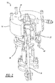
- a hydraulic valve gate actuator (generally shown at 10 in Figure 1 ) which provides improved life when used in a high volume production environment in a sequential valve gate for a mold used in an injection molding machine, such as an automotive injection molding production line.
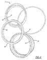
- the valve includes a kit of replacement seal parts (generally show in at 12 in Figure 4 ).
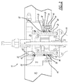
- the actuator 10 includes a housing 14 for insertion into a hot runner assembly tool back plate 16 having a movable valve gate pin18. Bore 20 in the housing receives an actuation piston 22 which is connected to the gate pin 18 for moving the pin up and down in the bore 20.
- a hydraulic chamber 24 in the assembly lifts the piston 22 upward and downward for actuation of the pin 18 for opening and closing a valve gate in an injection mold.
- the actuation piston 22 includes a centrally located circumferential double lip seal 26 which is preferably In a preferred embodiment, the double lip seal 26 is a Hytrel material (Polyester resin family) with a Shore A hardness of from generally about 90.25 to about 99.75 preferably about 95.
- a backing seal 28 placed underneath seal 26 in a circumferential slot 30 formed by two radially extending walls 32 and 34 in the piston 22. Backing seal 28 assures that the seal 26 is held securely in the slot 30 and has a Shore A hardness of generally from about 66.5 to about 73.5 preferably about 70.
- the wall of the bore 20 includes a pair of circumferential seals 36 and 38 for engaging the outer circumference of the piston 22.
- seals 36 and 38 are positioned in the housing axially on either side of the centrally located double lip seal 26 of the piston 22 for sealing and guiding the piston 22.
- the circumferential bore seals 36 and 38 are both the same type of two part seal.
- seals 36 and 38 each include an inner Teflon ring 42 which protects the bore in the event of seal failure and a second lip seal 40 made of a Viton material.
- Seal 40 of the present invention has a Shore A hardness of generally from about 76 to about 84, and preferably about 85.
- the Teflon ring 42 has a Shore D hardness of generally from about 52.25 to about 57.25 and preferably about 55. In and alternate embodiment there is a step in the ring 40 which forms an axial lip and the Teflon seal nests in the space formed next to the lip.
- Seal 44 is made of a nitrile material having a shore A hardness of generally from about 66.5 to about 73.5, preferably about 70 is used for sealing of the lower removable seal plate 46. Seal plate 46 is held to the actuator housing 14 by way of threaded fasteners 48.
- the seal 26 has a better wipe seal than the basic 'O' ring used in the prior art additionally seal 26 and the backing seal 28 take up all the space in the slot 30, which prevents the seal 26 from rolling in the slot.
- This increases the longevity of this seal arrangement since it is believed that the prior art rolling of the 'O' ring in the slot would lead to 'O' ring seal breakage and resulting failure of the actuator.
- the use of the inner Teflon ring seal 42 is robust enough to prevent metal on metal contact and deterioration in the event of other seal failures which also increases the longevity of the actuator.
- the seals when installed in the kit of parts as taught in the present invention, in combination, increase the longevity of the actuator over three fold over a similar actuation valve using conventional seals as shown in the drawings.
Landscapes
- Engineering & Computer Science (AREA)
- Mechanical Engineering (AREA)
- Manufacturing & Machinery (AREA)
- General Engineering & Computer Science (AREA)
- Moulds For Moulding Plastics Or The Like (AREA)
- Injection Moulding Of Plastics Or The Like (AREA)
Abstract
Description
- This application claims the benefit of
U.S. Provisional Application No. 62/245,496, filed October 23, 2015 - The present invention relates to a hydraulic valve gate actuator for a mold of an injection molding machine. More particularly the present invention relates to extending the life of a hydraulic valve gate actuator.
- Injection molding machines are common in manufacture today. In these machines molten plastic is forced through a valve gate into a mold for creating a solidified polymer part.
- Typically injection molding machines include an injection screw which forces heated polymer material through a hot runner assembly into a mold for creating a final molded part. The hot runner assembly includes one or more drop tubes which are attached to gates in the mold and movable pins are used for opening and closing of the valve gates during the injection cycle. The pin is lifted up and down by some sort of actuator, with hydraulic piston type actuator being the most commonly used.
- These actuators are designed to lift the pin from the gate seat for beginning injection and thereafter dropping the pin back into the gate when the injection of plastic at a particular site is complete. In most molds used today multiple gates are used in a mold to produce the best results with sequencing of the actuators and gates being common.
- Because of the use of multiple gates, failure or wearing of even one of the actuators can ruin the molding of an entire part. This is particularly a problem during high volume runs of parts where the longevity of these components is taken to the limits of their life. If a part molding program must be shut down because of a faulty valve gate actuator the entire hot runner assembly must be disassembled for replacement resulting in expensive and time consuming shut down and repair time. Not to mention the possibility of imperfect parts before the problem was noticed and corrected.
- For instance, it has been found that after 30,000 - 50,000 shots conventional sequential valve gate actuators are prone to leakage & sluggishness due to internal seal failures when supplied with standard issue seals. Some failures can become severe enough to destroy the cylinder housing from scouring.
- Sluggishness in pin movements creates part defects that are difficult to determine the root cause of. However, it is believed in many cases that these defects and part failures are due to poor reaction time of the actuators which make the SVG pin move erratically.
- Therefore, there remains a need in the art to provide a longer lasting hydraulic valve gate actuator which will withstand high quantity production runs such as are found in the automotive industry.
- In accordance with the present invention there is provided an improved life hydraulic valve gate actuator for a mold used in a injection molding. The actuator included a housing for insertion into a hot runner assembly having a movable valve gate pin. A bore in the housing receives an actuation piston which is connected to the gate pin. A hydraulic chamber in the assembly lifts the piston upward and downward for actuation of the pin in a valve gate. The actuation piston includes a centrally located circumferential double lip seal. The wall of the bore includes a pair of circumferential seals for engaging the outer circumference of the piston. The seals are positioned axially on either side of said centrally located double lip seal of the piston for sealing and guiding the piston. The circumferential bore seals include a Teflon ring which protects the bore in the event of seal failure and a second seal made of a Viton material. The seals in combination increase the longevity of the actuator over three fold than a similar actuation valve.
- The present invention will become more fully understood from the detailed description and the accompanying drawings, wherein:
-
Fig. 1 is a perspective view of a hydraulic actuator for a sequential valve gate; -
Fig. 2 is an exploded view of the actuator ofFig. 1 ; -
Fig. 3 is a sectional view of the actuator ofFigure 1 ; -
Fig. 4 is a perspective view of a valve seal replacement of the seals in the actuator ofFig 1 in accordance with the teachings of the present invention; -
Fig. 5 is a plan view of the piston of the actuator ofFig 1 showing a prior art 'O' ring seal; -
Fig. 6 is a plan view of a the piston ofFig 5 using the piston ring seal of the present invention; -
Fig. 7 is a view of the a prior art bore seal used in a valve actuator offigure 1 ; -
Fig. 8 is a bore seal in accordance with the seal of the present invention; -
Fig 9 is a main housing lip and backing seal used in the prior art; -
Fig. 10 is a main housing seal used in the present invention to replace the seal ofFig 9 ; and, -
Fig. 11 is a detailed sectional view of the seals and seal kit of the present invention. - The following description of the preferred embodiment(s) is merely exemplary in nature and is in no way intended to limit the invention, its application, or uses.
- In accordance with the present invention there is provided, a hydraulic valve gate actuator (generally shown at 10 in
Figure 1 ) which provides improved life when used in a high volume production environment in a sequential valve gate for a mold used in an injection molding machine, such as an automotive injection molding production line. - Generally, the valve includes a kit of replacement seal parts (generally show in at 12 in
Figure 4 ). Theactuator 10 includes ahousing 14 for insertion into a hot runner assemblytool back plate 16 having a movable valve gate pin18.Bore 20 in the housing receives anactuation piston 22 which is connected to thegate pin 18 for moving the pin up and down in thebore 20. - A
hydraulic chamber 24 in the assembly lifts thepiston 22 upward and downward for actuation of thepin 18 for opening and closing a valve gate in an injection mold. - The
actuation piston 22 includes a centrally located circumferentialdouble lip seal 26 which is preferably In a preferred embodiment, thedouble lip seal 26 is a Hytrel material (Polyester resin family) with a Shore A hardness of from generally about 90.25 to about 99.75 preferably about 95. Abacking seal 28 placed underneathseal 26 in acircumferential slot 30 formed by two radially extendingwalls piston 22. Backingseal 28 assures that theseal 26 is held securely in theslot 30 and has a Shore A hardness of generally from about 66.5 to about 73.5 preferably about 70. The wall of thebore 20 includes a pair ofcircumferential seals piston 22. Theseals double lip seal 26 of thepiston 22 for sealing and guiding thepiston 22. Thecircumferential bore seals Figs 4 and11 seals ring 42 which protects the bore in the event of seal failure and asecond lip seal 40 made of a Viton material.Seal 40 of the present invention has a Shore A hardness of generally from about 76 to about 84, and preferably about 85. The Teflonring 42 has a Shore D hardness of generally from about 52.25 to about 57.25 and preferably about 55. In and alternate embodiment there is a step in thering 40 which forms an axial lip and the Teflon seal nests in the space formed next to the lip. -
Seal 44 is made of a nitrile material having a shore A hardness of generally from about 66.5 to about 73.5, preferably about 70 is used for sealing of the lowerremovable seal plate 46.Seal plate 46 is held to theactuator housing 14 by way of threadedfasteners 48. - In operation the
seal 26 has a better wipe seal than the basic 'O' ring used in the prior art additionally seal 26 and thebacking seal 28 take up all the space in theslot 30, which prevents theseal 26 from rolling in the slot. This increases the longevity of this seal arrangement since it is believed that the prior art rolling of the 'O' ring in the slot would lead to 'O' ring seal breakage and resulting failure of the actuator. Additionally, the use of the innerTeflon ring seal 42 is robust enough to prevent metal on metal contact and deterioration in the event of other seal failures which also increases the longevity of the actuator. The seals when installed in the kit of parts as taught in the present invention, in combination, increase the longevity of the actuator over three fold over a similar actuation valve using conventional seals as shown in the drawings. - The description of the invention is merely exemplary in nature and, thus, variations that do not depart from the gist of the invention are intended to be within the scope of the invention. Such variations are not to be regarded as a departure from the spirit and scope of the invention.
Claims (14)
- A hydraulic valve gate actuator for a mold used in an injection molding machine comprising:a housing adapted or insertion into a hot runner assembly having a movable valve gate pin;a bore in the housing for receiving of an actuation piston the actuation piston being connected to the gate pin;the actuation piston including a centrally located double lip seal; andthe bore including a pair of circumferential seals for engaging the outer circumference of the piston and positioned axially on either side of the centrally located double lip seal, the circumferential seals including a Teflon ring which protects the bore in the event of seal failure and a second seal made of a Viton material.
- The hydraulic valve gate actuator of claim 1, wherein the second seal is a lip seal.
- The hydraulic valve gate actuator of claim 1, wherein the Teflon ring has an outer circumference so that it fits inside the inside diameter of the second seal.
- The hydraulic valve gate actuator of claim 1, further comprising a second seal concentrically spaced but within the same groove as the double lip seal; and/or
wherein the groove is formed by a pair of circumferential walls formed around the outer periphery of the piston. - The hydraulic valve gate actuator of claim 1, wherein the inner diameter of the circumferential seals is from 4% to 6% smaller than the outside diameter of the actuation piston; or
wherein the inner diameter of the circumferential seals is from 5% smaller than the outside diameter of the actuation piston. - The hydraulic valve gate actuator of claim 1, wherein the double lipped seal has a shore A hardness of from about 90.25 to about 99.75; and/or
wherein the Teflon ring has a shore D hardness of from about 52.25 to about 57.25; and/or
wherein the second seal has a shore A hardness of from about 76 to about 84. - A seal kit of parts for use in replacement of seals in a hydraulic valve gate actuator for an injection molding machine comprising:a double lipped piston seal, two pairs of wall seals each including an inner Teflon seal and an outer elastomeric seal.
- The seal kit of parts for use in replacement of seals in a hydraulic valve gate actuator for an injection molding machine of claim 7, further comprising an axially spaced circumferential seal for axial placement in the piston groove.
- The seal kit of parts of claim 8, wherein the hydraulic valve gate actuator includes: a housing adapted for insertion into a hot runner assembly having a movable valve gate pin; a bore in the housing for receiving of an actuation piston the actuation piston being connected to the gate pin; the actuation piston including a centrally located slot for receiving the double lipped piston seal;
the bore in the housing including surfaces forming a pair of axial spaced slots for receiving the pair of circumferential seals which engage the outer circumference of the piston and wherein the seals are positioned axially on either side of the centrally located double lip seal, the circumferential seals including a first Teflon ring which protects the bore in the event of seal failure and a second seal made of a Viton material. - The seal kit of parts of claim 9, wherein the Teflon ring has an outer circumference so that it fits inside the inside diameter of the second seal.
- The seal kit of parts of claim 9, further comprising a second seal axially spaced but within the same groove as the double lipped piston seal; and/or
wherein the slot is formed by a pair of circumferential walls formed around the outer periphery of the piston. - The seal kit of parts of claim 9, wherein the inner diameter of the circumferential seals is from 4% to 6% smaller than the outside diameter of the actuation piston; or
wherein the inner diameter of the circumferential seals is 5% smaller than the outside diameter of the actuation piston. - The seal kit of parts of claim 9, wherein the double lipped seal has a shore A hardness of from about 90.25 to about 99.75; and/or
wherein the Teflon ring has a shore D hardness of from about 52.25 to about 57.25; and/or
wherein the second seal has a shore A hardness of from about 76 to about 84. - A process for enhancing the life cycle characteristics of a hydraulic valve gate actuator for a mold used in an injection molding machine comprising the steps of:providing a housing adapted or insertion into a hot runner assembly having a movable valve gate pin with a bore in the housing for receiving of an actuation piston the actuation piston being connected to the gate pin; and replacing the seals in the actuator with replacement seals including a centrally located double lip seal; andthe bore including a pair of circumferential seals for engaging the outer circumference of the piston and positioned axially on either side of the centrally located double lip seal, the circumferential seals including a Teflon ring which protects the bore in the event of seal failure and a concentric second seal made of a Viton material.
Applications Claiming Priority (1)
| Application Number | Priority Date | Filing Date | Title |
|---|---|---|---|
| US201562245496P | 2015-10-23 | 2015-10-23 |
Publications (2)
| Publication Number | Publication Date |
|---|---|
| EP3159133A1 true EP3159133A1 (en) | 2017-04-26 |
| EP3159133B1 EP3159133B1 (en) | 2020-08-12 |
Family
ID=57218705
Family Applications (1)
| Application Number | Title | Priority Date | Filing Date |
|---|---|---|---|
| EP16194953.2A Active EP3159133B1 (en) | 2015-10-23 | 2016-10-21 | Valve gate actuator for an plastic injection mold and internal seal upgrade |
Country Status (5)
| Country | Link |
|---|---|
| US (1) | US10267429B2 (en) |
| EP (1) | EP3159133B1 (en) |
| KR (1) | KR20170048179A (en) |
| CN (1) | CN106881830B (en) |
| CA (1) | CA2946176C (en) |
Citations (1)
| Publication number | Priority date | Publication date | Assignee | Title |
|---|---|---|---|---|
| WO1998056560A1 (en) * | 1997-06-13 | 1998-12-17 | Dynisco Hotrunners, Inc. | Valve pin actuator |
Family Cites Families (12)
| Publication number | Priority date | Publication date | Assignee | Title |
|---|---|---|---|---|
| US2446224A (en) * | 1945-05-03 | 1948-08-03 | Ramsey Accessories Mfg Corp | Hydraulic control oil ring |
| US3057630A (en) * | 1958-08-08 | 1962-10-09 | Sneed John | Seal |
| US3171334A (en) * | 1963-07-05 | 1965-03-02 | Honeywell Inc | Control apparatus |
| US4262915A (en) * | 1978-04-17 | 1981-04-21 | Commercial Shearing, Inc. | Low friction drag seals |
| GB2177464B (en) * | 1985-06-29 | 1988-06-02 | Dowty Seals Ltd | Sealing assembly |
| DE3603669A1 (en) * | 1986-02-06 | 1987-08-13 | Busak & Luyken Gmbh & Co | DOUBLE SCRAPER ARRANGEMENT |
| US5113747A (en) * | 1989-01-23 | 1992-05-19 | Pignerol Herve Y | High pressure piston sealing system and method of its assembly |
| US6568313B2 (en) * | 2001-03-07 | 2003-05-27 | Smc Kabushiki Kaisha | Fluid pressure cylinder apparatus |
| US6959913B2 (en) * | 2003-06-13 | 2005-11-01 | Dynamic Air Inc. | Actuator |
| WO2008072738A1 (en) * | 2006-12-14 | 2008-06-19 | Nok Corporation | Sealing device and method of manufacturing the device |
| DE102010055747B3 (en) * | 2010-12-22 | 2012-07-05 | Magna Steyr Fahrzeugtechnik Ag & Co Kg | pressure reducer |
| EP2540999B1 (en) * | 2011-06-29 | 2014-07-09 | Caterpillar Motoren GmbH & Co. KG | Valve stem seal for a combustion engine |
-
2016
- 2016-07-08 US US15/205,457 patent/US10267429B2/en active Active
- 2016-10-19 KR KR1020160135459A patent/KR20170048179A/en not_active Abandoned
- 2016-10-21 CA CA2946176A patent/CA2946176C/en active Active
- 2016-10-21 EP EP16194953.2A patent/EP3159133B1/en active Active
- 2016-10-24 CN CN201610926278.0A patent/CN106881830B/en not_active Expired - Fee Related
Patent Citations (1)
| Publication number | Priority date | Publication date | Assignee | Title |
|---|---|---|---|---|
| WO1998056560A1 (en) * | 1997-06-13 | 1998-12-17 | Dynisco Hotrunners, Inc. | Valve pin actuator |
Non-Patent Citations (4)
| Title |
|---|
| ANONYMOUS: "Designing with Fluoroelastomers", 26 February 2004 (2004-02-26), pages 1 - 14, XP055354317, Retrieved from the Internet <URL:http://www.zrunek.at/viton-fkm-fpm-fluorelastomere/download/zruelast-fpm-designing-with-fluoroelastomers.pdf> [retrieved on 20170313] * |
| ANONYMOUS: "Seal kits for actuators", COMPONENTS AND SPARE PARTS FOR HOT RUNNER SYSTEMS, 12 July 2007 (2007-07-12), pages 22 - 22, XP055353829, Retrieved from the Internet <URL:http://www.niulira.com/cat/synventive/catalogue/englisch/images/MK-PRM.BRM.GB-P.SPARTS.pdf> [retrieved on 20170310] * |
| ANOYMOUS: "Fluid Power Seal Design Guide", CATALOG EPS5370, 9 January 2015 (2015-01-09), pages 1 - 46, XP055354571, Retrieved from the Internet <URL:https://www.parker.com/literature/Engineered%20Polymer%20Systems/5370.pdf> [retrieved on 20170314] * |
| RUDOLF KACHEL: "Wartung und Instandhaltung / Service für Nadelbetätigungszylinder der QCVG16 Serie", 26 March 2015 (2015-03-26), pages 292 - 302, XP055353735, Retrieved from the Internet <URL:http://www.synventive.com/uploadedFiles/Service_and_Support/Service_Manual/08-70_QCVG16_DE.pdf> [retrieved on 20170310] * |
Also Published As
| Publication number | Publication date |
|---|---|
| US10267429B2 (en) | 2019-04-23 |
| CA2946176C (en) | 2023-10-17 |
| CN106881830B (en) | 2020-10-27 |
| CA2946176A1 (en) | 2017-04-23 |
| EP3159133B1 (en) | 2020-08-12 |
| CN106881830A (en) | 2017-06-23 |
| US20170114921A1 (en) | 2017-04-27 |
| KR20170048179A (en) | 2017-05-08 |
Similar Documents
| Publication | Publication Date | Title |
|---|---|---|
| US9067346B2 (en) | Seal and procedure for its production | |
| KR101351364B1 (en) | Flow rate control valve and assembly method therefor | |
| CN104736216B (en) | Filtration equipment with sealing device | |
| EP2992210B1 (en) | Wax actuator with high cycle life | |
| JP6442753B2 (en) | Manufacturing method of sealing device | |
| US10267429B2 (en) | Plastic injection mold—SVG actuator—internal seal upgrade | |
| US20170226958A1 (en) | Spring Energized Cylinder Liner Seal | |
| CN105841410A (en) | Electronic expansion valve | |
| US10054261B2 (en) | Mono-material divider block assembly | |
| CN209043556U (en) | Ground experiment device with disc spring compensation function | |
| KR101847099B1 (en) | The injection molding machine that have a valve pin length control apparatus | |
| US10611069B2 (en) | Injection-molding method for mesh filter, injection-molding mold, and mesh filter | |
| JP2018079667A (en) | Method for molding disc of soft seal gate valve and apparatus for molding disc thereof | |
| KR102040512B1 (en) | A gate valve for injection molding | |
| CN103402729A (en) | Injection-molding machine | |
| CN109297655A (en) | Ground experiment device with disc spring compensation function | |
| CN209430392U (en) | Cone valve for cone valve type filling industrial pump | |
| CN103672116A (en) | Metering solenoid valve for common rail | |
| CN205467056U (en) | Mould is made to rubber flashboard for gate valve | |
| JP6288185B2 (en) | Sealing device | |
| KR20140115083A (en) | Bearing and roller and manufacturing method thereof | |
| JP6732036B2 (en) | Nozzle for injection molding machine | |
| KR101700710B1 (en) | Manufacturing method of piston seal ring assembly | |
| CN106393594A (en) | An Injection Plastic Mold That Can Prevent the Deformation of the Needle Valve | |
| KR101914390B1 (en) | Springless Vent Plug for Tire Cure Mold |
Legal Events
| Date | Code | Title | Description |
|---|---|---|---|
| PUAI | Public reference made under article 153(3) epc to a published international application that has entered the european phase |
Free format text: ORIGINAL CODE: 0009012 |
|
| STAA | Information on the status of an ep patent application or granted ep patent |
Free format text: STATUS: REQUEST FOR EXAMINATION WAS MADE |
|
| 17P | Request for examination filed |
Effective date: 20161021 |
|
| AK | Designated contracting states |
Kind code of ref document: A1 Designated state(s): AL AT BE BG CH CY CZ DE DK EE ES FI FR GB GR HR HU IE IS IT LI LT LU LV MC MK MT NL NO PL PT RO RS SE SI SK SM TR |
|
| AX | Request for extension of the european patent |
Extension state: BA ME |
|
| STAA | Information on the status of an ep patent application or granted ep patent |
Free format text: STATUS: EXAMINATION IS IN PROGRESS |
|
| 17Q | First examination report despatched |
Effective date: 20190322 |
|
| GRAP | Despatch of communication of intention to grant a patent |
Free format text: ORIGINAL CODE: EPIDOSNIGR1 |
|
| STAA | Information on the status of an ep patent application or granted ep patent |
Free format text: STATUS: GRANT OF PATENT IS INTENDED |
|
| INTG | Intention to grant announced |
Effective date: 20200306 |
|
| GRAS | Grant fee paid |
Free format text: ORIGINAL CODE: EPIDOSNIGR3 |
|
| GRAA | (expected) grant |
Free format text: ORIGINAL CODE: 0009210 |
|
| STAA | Information on the status of an ep patent application or granted ep patent |
Free format text: STATUS: THE PATENT HAS BEEN GRANTED |
|
| AK | Designated contracting states |
Kind code of ref document: B1 Designated state(s): AL AT BE BG CH CY CZ DE DK EE ES FI FR GB GR HR HU IE IS IT LI LT LU LV MC MK MT NL NO PL PT RO RS SE SI SK SM TR |
|
| REG | Reference to a national code |
Ref country code: CH Ref legal event code: EP |
|
| REG | Reference to a national code |
Ref country code: IE Ref legal event code: FG4D |
|
| REG | Reference to a national code |
Ref country code: DE Ref legal event code: R096 Ref document number: 602016041758 Country of ref document: DE |
|
| REG | Reference to a national code |
Ref country code: AT Ref legal event code: REF Ref document number: 1301124 Country of ref document: AT Kind code of ref document: T Effective date: 20200915 |
|
| REG | Reference to a national code |
Ref country code: LT Ref legal event code: MG4D |
|
| REG | Reference to a national code |
Ref country code: NL Ref legal event code: MP Effective date: 20200812 |
|
| PG25 | Lapsed in a contracting state [announced via postgrant information from national office to epo] |
Ref country code: LT Free format text: LAPSE BECAUSE OF FAILURE TO SUBMIT A TRANSLATION OF THE DESCRIPTION OR TO PAY THE FEE WITHIN THE PRESCRIBED TIME-LIMIT Effective date: 20200812 Ref country code: SE Free format text: LAPSE BECAUSE OF FAILURE TO SUBMIT A TRANSLATION OF THE DESCRIPTION OR TO PAY THE FEE WITHIN THE PRESCRIBED TIME-LIMIT Effective date: 20200812 Ref country code: BG Free format text: LAPSE BECAUSE OF FAILURE TO SUBMIT A TRANSLATION OF THE DESCRIPTION OR TO PAY THE FEE WITHIN THE PRESCRIBED TIME-LIMIT Effective date: 20201112 Ref country code: GR Free format text: LAPSE BECAUSE OF FAILURE TO SUBMIT A TRANSLATION OF THE DESCRIPTION OR TO PAY THE FEE WITHIN THE PRESCRIBED TIME-LIMIT Effective date: 20201113 Ref country code: HR Free format text: LAPSE BECAUSE OF FAILURE TO SUBMIT A TRANSLATION OF THE DESCRIPTION OR TO PAY THE FEE WITHIN THE PRESCRIBED TIME-LIMIT Effective date: 20200812 Ref country code: NO Free format text: LAPSE BECAUSE OF FAILURE TO SUBMIT A TRANSLATION OF THE DESCRIPTION OR TO PAY THE FEE WITHIN THE PRESCRIBED TIME-LIMIT Effective date: 20201112 Ref country code: FI Free format text: LAPSE BECAUSE OF FAILURE TO SUBMIT A TRANSLATION OF THE DESCRIPTION OR TO PAY THE FEE WITHIN THE PRESCRIBED TIME-LIMIT Effective date: 20200812 |
|
| REG | Reference to a national code |
Ref country code: AT Ref legal event code: MK05 Ref document number: 1301124 Country of ref document: AT Kind code of ref document: T Effective date: 20200812 |
|
| PG25 | Lapsed in a contracting state [announced via postgrant information from national office to epo] |
Ref country code: RS Free format text: LAPSE BECAUSE OF FAILURE TO SUBMIT A TRANSLATION OF THE DESCRIPTION OR TO PAY THE FEE WITHIN THE PRESCRIBED TIME-LIMIT Effective date: 20200812 Ref country code: LV Free format text: LAPSE BECAUSE OF FAILURE TO SUBMIT A TRANSLATION OF THE DESCRIPTION OR TO PAY THE FEE WITHIN THE PRESCRIBED TIME-LIMIT Effective date: 20200812 Ref country code: PL Free format text: LAPSE BECAUSE OF FAILURE TO SUBMIT A TRANSLATION OF THE DESCRIPTION OR TO PAY THE FEE WITHIN THE PRESCRIBED TIME-LIMIT Effective date: 20200812 Ref country code: NL Free format text: LAPSE BECAUSE OF FAILURE TO SUBMIT A TRANSLATION OF THE DESCRIPTION OR TO PAY THE FEE WITHIN THE PRESCRIBED TIME-LIMIT Effective date: 20200812 Ref country code: IS Free format text: LAPSE BECAUSE OF FAILURE TO SUBMIT A TRANSLATION OF THE DESCRIPTION OR TO PAY THE FEE WITHIN THE PRESCRIBED TIME-LIMIT Effective date: 20201212 |
|
| PG25 | Lapsed in a contracting state [announced via postgrant information from national office to epo] |
Ref country code: EE Free format text: LAPSE BECAUSE OF FAILURE TO SUBMIT A TRANSLATION OF THE DESCRIPTION OR TO PAY THE FEE WITHIN THE PRESCRIBED TIME-LIMIT Effective date: 20200812 Ref country code: SM Free format text: LAPSE BECAUSE OF FAILURE TO SUBMIT A TRANSLATION OF THE DESCRIPTION OR TO PAY THE FEE WITHIN THE PRESCRIBED TIME-LIMIT Effective date: 20200812 Ref country code: RO Free format text: LAPSE BECAUSE OF FAILURE TO SUBMIT A TRANSLATION OF THE DESCRIPTION OR TO PAY THE FEE WITHIN THE PRESCRIBED TIME-LIMIT Effective date: 20200812 Ref country code: CZ Free format text: LAPSE BECAUSE OF FAILURE TO SUBMIT A TRANSLATION OF THE DESCRIPTION OR TO PAY THE FEE WITHIN THE PRESCRIBED TIME-LIMIT Effective date: 20200812 Ref country code: DK Free format text: LAPSE BECAUSE OF FAILURE TO SUBMIT A TRANSLATION OF THE DESCRIPTION OR TO PAY THE FEE WITHIN THE PRESCRIBED TIME-LIMIT Effective date: 20200812 |
|
| REG | Reference to a national code |
Ref country code: DE Ref legal event code: R097 Ref document number: 602016041758 Country of ref document: DE |
|
| PG25 | Lapsed in a contracting state [announced via postgrant information from national office to epo] |
Ref country code: AT Free format text: LAPSE BECAUSE OF FAILURE TO SUBMIT A TRANSLATION OF THE DESCRIPTION OR TO PAY THE FEE WITHIN THE PRESCRIBED TIME-LIMIT Effective date: 20200812 Ref country code: AL Free format text: LAPSE BECAUSE OF FAILURE TO SUBMIT A TRANSLATION OF THE DESCRIPTION OR TO PAY THE FEE WITHIN THE PRESCRIBED TIME-LIMIT Effective date: 20200812 Ref country code: ES Free format text: LAPSE BECAUSE OF FAILURE TO SUBMIT A TRANSLATION OF THE DESCRIPTION OR TO PAY THE FEE WITHIN THE PRESCRIBED TIME-LIMIT Effective date: 20200812 |
|
| REG | Reference to a national code |
Ref country code: CH Ref legal event code: PL |
|
| PLBE | No opposition filed within time limit |
Free format text: ORIGINAL CODE: 0009261 |
|
| STAA | Information on the status of an ep patent application or granted ep patent |
Free format text: STATUS: NO OPPOSITION FILED WITHIN TIME LIMIT |
|
| PG25 | Lapsed in a contracting state [announced via postgrant information from national office to epo] |
Ref country code: SK Free format text: LAPSE BECAUSE OF FAILURE TO SUBMIT A TRANSLATION OF THE DESCRIPTION OR TO PAY THE FEE WITHIN THE PRESCRIBED TIME-LIMIT Effective date: 20200812 Ref country code: MC Free format text: LAPSE BECAUSE OF FAILURE TO SUBMIT A TRANSLATION OF THE DESCRIPTION OR TO PAY THE FEE WITHIN THE PRESCRIBED TIME-LIMIT Effective date: 20200812 Ref country code: LU Free format text: LAPSE BECAUSE OF NON-PAYMENT OF DUE FEES Effective date: 20201021 |
|
| REG | Reference to a national code |
Ref country code: BE Ref legal event code: MM Effective date: 20201031 |
|
| 26N | No opposition filed |
Effective date: 20210514 |
|
| PG25 | Lapsed in a contracting state [announced via postgrant information from national office to epo] |
Ref country code: IT Free format text: LAPSE BECAUSE OF FAILURE TO SUBMIT A TRANSLATION OF THE DESCRIPTION OR TO PAY THE FEE WITHIN THE PRESCRIBED TIME-LIMIT Effective date: 20200812 |
|
| PG25 | Lapsed in a contracting state [announced via postgrant information from national office to epo] |
Ref country code: SI Free format text: LAPSE BECAUSE OF FAILURE TO SUBMIT A TRANSLATION OF THE DESCRIPTION OR TO PAY THE FEE WITHIN THE PRESCRIBED TIME-LIMIT Effective date: 20200812 Ref country code: LI Free format text: LAPSE BECAUSE OF NON-PAYMENT OF DUE FEES Effective date: 20201031 Ref country code: BE Free format text: LAPSE BECAUSE OF NON-PAYMENT OF DUE FEES Effective date: 20201031 Ref country code: CH Free format text: LAPSE BECAUSE OF NON-PAYMENT OF DUE FEES Effective date: 20201031 |
|
| PG25 | Lapsed in a contracting state [announced via postgrant information from national office to epo] |
Ref country code: IE Free format text: LAPSE BECAUSE OF NON-PAYMENT OF DUE FEES Effective date: 20201021 |
|
| PG25 | Lapsed in a contracting state [announced via postgrant information from national office to epo] |
Ref country code: TR Free format text: LAPSE BECAUSE OF FAILURE TO SUBMIT A TRANSLATION OF THE DESCRIPTION OR TO PAY THE FEE WITHIN THE PRESCRIBED TIME-LIMIT Effective date: 20200812 Ref country code: MT Free format text: LAPSE BECAUSE OF FAILURE TO SUBMIT A TRANSLATION OF THE DESCRIPTION OR TO PAY THE FEE WITHIN THE PRESCRIBED TIME-LIMIT Effective date: 20200812 Ref country code: CY Free format text: LAPSE BECAUSE OF FAILURE TO SUBMIT A TRANSLATION OF THE DESCRIPTION OR TO PAY THE FEE WITHIN THE PRESCRIBED TIME-LIMIT Effective date: 20200812 |
|
| PG25 | Lapsed in a contracting state [announced via postgrant information from national office to epo] |
Ref country code: MK Free format text: LAPSE BECAUSE OF FAILURE TO SUBMIT A TRANSLATION OF THE DESCRIPTION OR TO PAY THE FEE WITHIN THE PRESCRIBED TIME-LIMIT Effective date: 20200812 |
|
| PG25 | Lapsed in a contracting state [announced via postgrant information from national office to epo] |
Ref country code: PT Free format text: LAPSE BECAUSE OF FAILURE TO SUBMIT A TRANSLATION OF THE DESCRIPTION OR TO PAY THE FEE WITHIN THE PRESCRIBED TIME-LIMIT Effective date: 20200812 |
|
| PGFP | Annual fee paid to national office [announced via postgrant information from national office to epo] |
Ref country code: FR Payment date: 20220908 Year of fee payment: 7 |
|
| P01 | Opt-out of the competence of the unified patent court (upc) registered |
Effective date: 20230517 |
|
| PGFP | Annual fee paid to national office [announced via postgrant information from national office to epo] |
Ref country code: GB Payment date: 20230831 Year of fee payment: 8 |
|
| PGFP | Annual fee paid to national office [announced via postgrant information from national office to epo] |
Ref country code: DE Payment date: 20230830 Year of fee payment: 8 |
|
| PG25 | Lapsed in a contracting state [announced via postgrant information from national office to epo] |
Ref country code: FR Free format text: LAPSE BECAUSE OF NON-PAYMENT OF DUE FEES Effective date: 20231031 |
|
| REG | Reference to a national code |
Ref country code: DE Ref legal event code: R119 Ref document number: 602016041758 Country of ref document: DE |
|
| GBPC | Gb: european patent ceased through non-payment of renewal fee |
Effective date: 20241021 |
|
| PG25 | Lapsed in a contracting state [announced via postgrant information from national office to epo] |
Ref country code: DE Free format text: LAPSE BECAUSE OF NON-PAYMENT OF DUE FEES Effective date: 20250501 |
|
| PG25 | Lapsed in a contracting state [announced via postgrant information from national office to epo] |
Ref country code: GB Free format text: LAPSE BECAUSE OF NON-PAYMENT OF DUE FEES Effective date: 20241021 |