EP3159024A1 - Connector for blood circuit - Google Patents
Connector for blood circuit Download PDFInfo
- Publication number
- EP3159024A1 EP3159024A1 EP14895308.6A EP14895308A EP3159024A1 EP 3159024 A1 EP3159024 A1 EP 3159024A1 EP 14895308 A EP14895308 A EP 14895308A EP 3159024 A1 EP3159024 A1 EP 3159024A1
- Authority
- EP
- European Patent Office
- Prior art keywords
- plug
- main body
- opening end
- blood circuit
- circuit connector
- Prior art date
- Legal status (The legal status is an assumption and is not a legal conclusion. Google has not performed a legal analysis and makes no representation as to the accuracy of the status listed.)
- Granted
Links
Images



Classifications
-
- A—HUMAN NECESSITIES
- A61—MEDICAL OR VETERINARY SCIENCE; HYGIENE
- A61M—DEVICES FOR INTRODUCING MEDIA INTO, OR ONTO, THE BODY; DEVICES FOR TRANSDUCING BODY MEDIA OR FOR TAKING MEDIA FROM THE BODY; DEVICES FOR PRODUCING OR ENDING SLEEP OR STUPOR
- A61M39/00—Tubes, tube connectors, tube couplings, valves, access sites or the like, specially adapted for medical use
- A61M39/10—Tube connectors or tube couplings
- A61M39/12—Tube connectors or tube couplings for joining a flexible tube to a rigid attachment
-
- A—HUMAN NECESSITIES
- A61—MEDICAL OR VETERINARY SCIENCE; HYGIENE
- A61M—DEVICES FOR INTRODUCING MEDIA INTO, OR ONTO, THE BODY; DEVICES FOR TRANSDUCING BODY MEDIA OR FOR TAKING MEDIA FROM THE BODY; DEVICES FOR PRODUCING OR ENDING SLEEP OR STUPOR
- A61M1/00—Suction or pumping devices for medical purposes; Devices for carrying-off, for treatment of, or for carrying-over, body-liquids; Drainage systems
- A61M1/36—Other treatment of blood in a by-pass of the natural circulatory system, e.g. temperature adaptation, irradiation ; Extra-corporeal blood circuits
- A61M1/3621—Extra-corporeal blood circuits
- A61M1/367—Circuit parts not covered by the preceding subgroups of group A61M1/3621
-
- A—HUMAN NECESSITIES
- A61—MEDICAL OR VETERINARY SCIENCE; HYGIENE
- A61M—DEVICES FOR INTRODUCING MEDIA INTO, OR ONTO, THE BODY; DEVICES FOR TRANSDUCING BODY MEDIA OR FOR TAKING MEDIA FROM THE BODY; DEVICES FOR PRODUCING OR ENDING SLEEP OR STUPOR
- A61M1/00—Suction or pumping devices for medical purposes; Devices for carrying-off, for treatment of, or for carrying-over, body-liquids; Drainage systems
- A61M1/14—Dialysis systems; Artificial kidneys; Blood oxygenators ; Reciprocating systems for treatment of body fluids, e.g. single needle systems for hemofiltration or pheresis
-
- A—HUMAN NECESSITIES
- A61—MEDICAL OR VETERINARY SCIENCE; HYGIENE
- A61M—DEVICES FOR INTRODUCING MEDIA INTO, OR ONTO, THE BODY; DEVICES FOR TRANSDUCING BODY MEDIA OR FOR TAKING MEDIA FROM THE BODY; DEVICES FOR PRODUCING OR ENDING SLEEP OR STUPOR
- A61M1/00—Suction or pumping devices for medical purposes; Devices for carrying-off, for treatment of, or for carrying-over, body-liquids; Drainage systems
- A61M1/36—Other treatment of blood in a by-pass of the natural circulatory system, e.g. temperature adaptation, irradiation ; Extra-corporeal blood circuits
- A61M1/3621—Extra-corporeal blood circuits
- A61M1/3624—Level detectors; Level control
-
- A—HUMAN NECESSITIES
- A61—MEDICAL OR VETERINARY SCIENCE; HYGIENE
- A61M—DEVICES FOR INTRODUCING MEDIA INTO, OR ONTO, THE BODY; DEVICES FOR TRANSDUCING BODY MEDIA OR FOR TAKING MEDIA FROM THE BODY; DEVICES FOR PRODUCING OR ENDING SLEEP OR STUPOR
- A61M1/00—Suction or pumping devices for medical purposes; Devices for carrying-off, for treatment of, or for carrying-over, body-liquids; Drainage systems
- A61M1/36—Other treatment of blood in a by-pass of the natural circulatory system, e.g. temperature adaptation, irradiation ; Extra-corporeal blood circuits
- A61M1/3621—Extra-corporeal blood circuits
- A61M1/3627—Degassing devices; Buffer reservoirs; Drip chambers; Blood filters
-
- A—HUMAN NECESSITIES
- A61—MEDICAL OR VETERINARY SCIENCE; HYGIENE
- A61M—DEVICES FOR INTRODUCING MEDIA INTO, OR ONTO, THE BODY; DEVICES FOR TRANSDUCING BODY MEDIA OR FOR TAKING MEDIA FROM THE BODY; DEVICES FOR PRODUCING OR ENDING SLEEP OR STUPOR
- A61M39/00—Tubes, tube connectors, tube couplings, valves, access sites or the like, specially adapted for medical use
- A61M39/22—Valves or arrangement of valves
- A61M39/28—Clamping means for squeezing flexible tubes, e.g. roller clamps
Definitions
- the present invention relates to a blood circuit connector, and particularly to a blood circuit connector including: a main body provided with a through hole through which a tube can be inserted from both ends; and a plug connected to an outer circumferential surface of the main body, and allowing the plug to be detachably attached to one end of the main body.
- An extracorporeal circulation circuit used for hemodialysis and the like is formed of an artery-side blood circuit and a vein-side blood circuit.
- the artery-side blood circuit includes a tube connected to one end of the hemodialyzer and used for connecting various kinds of devices.
- the tube has a tip end to which a blood circuit connector is attached, which is used for introducing another connector connected to an artery-side puncture needle.
- the vein-side blood circuit includes a tube connected to the other end of the hemodialyzer and used for connecting various kinds of devices.
- the tube has a tip end to which a blood circuit connector is attached, which is used for introducing another connector connected to a vein-side puncture needle.
- the blood circuit connector has a cylindrical shape provided with a through hole such that the above-described connector can be introduced into both ends thereof. Furthermore, it is preferable that the blood circuit connector is kept clean from the hygiene point of view.
- a plug for closing an opening at one end until use is provided in order to prevent contamination by various bacteria.
- Japanese Patent Laying-Open No. 2011-55911 (PTD 1) is cited as a document disclosing a blood circuit connector provided with a plug for closing an opening at one end.
- the blood circuit connector disclosed in PTD 1 includes: a main body provided therein with a through hole and separable between one end and the other end; and a plug connected to the main body.
- the main body is provided at its one end with a first opening that communicates with the through hole.
- the plug is configured to close the first opening in the attached state where this plug is attached to the main body.
- the first opening can be closed by the plug until it becomes necessary to be used during the priming process or the like, so that the opening end of the main body located on the first opening side can be prevented from being contaminated by various bacteria.
- PTD 1 Japanese Patent Laying-Open No. 2011-55911
- a connector of the other blood circuit (including an adapter for connecting the connector) or a connector for a puncture needle is connected to one end of the main body of the blood circuit connector. In this case, it is necessary to remove the plug closing the opening at one end of the main body.
- An object of the present invention is to provide a blood circuit connector that allows easy removal of a plug and also allows easy formation of an extracorporeal circulation circuit.
- a blood circuit connector includes: a main body having a cylindrical shape and having a through hole provided therein to have one end provided with a first opening end and the other end provided with a second opening end; a plug having a bottomed cylindrical shape and detachably attached to the first opening end; and a connection part having flexibility and configured to connect the main body and the plug.
- the plug includes a side wall loosely fitted to an outer circumferential surface of the first opening end and a bottom facing the first opening end in an extending direction of an axis line of the main body in an attached state where the plug is attached to the first opening end.
- the connection part includes a first fixed end connected to the side wall of the plug, a second fixed end connected to an outer circumferential surface of the main body, and a curved part located between the first fixed end and the second fixed end and expanding in a direction away from the main body.
- the curved part In the attached state, the curved part is pushed in a direction approaching the outer circumferential surface of the main body such that the curved part extends, to cancel a loosely fitted state between the side wall of the plug and the outer circumferential surface of the first opening end, so as to remove the plug from the first opening end.
- connection part further includes an elastic force generating part located between the first fixed end and the curved part, and flexibly deformed in the attached state so as to generate elastic force.
- the plug is attached to the first opening end as the plug swings against the elastic force generated by the elastic force generating part such that an axis line of the plug extends in line with the axis line of the main body.
- the loosely fitted state between the side wall of the plug and the outer circumferential surface of the first opening end is cancelled, to cause the plug to swing with restoring force produced based on the elastic force generated by the elastic force generating part, so as to move the plug away from above the axis line of the main body.
- the elastic force generating part has an approximately S-shape.
- the main body, the plug and the connection part are integrally molded by injection molding.
- Fig. 1 is a schematic diagram of an extracorporeal circulation circuit in which a blood circuit connector is used, according to an embodiment of the present invention. Referring to Fig. 1 , an extracorporeal circulation circuit 1 in which a blood circuit connector 100 according to the present embodiment is used will be hereinafter described.
- extracorporeal circulation circuit 1 in which blood circuit connector 100 according to the present embodiment is used is configured by connecting an artery-side blood circuit 20 to one end of a dialyzer 10, and connecting a vein-side blood circuit 30 to the other end of dialyzer 10.
- Dialyzer 10 serves as a device for purifying blood by bringing blood and a dialysis fluid into contact with each other through a dialysis membrane, to cause diffusion by the concentration difference of solutes and ultrafiltration by the static pressure difference, thereby removing and supplying the solutes, and also removing moisture.
- an artery-side drip chamber 40, a physiological-saline supply part 60 for example filled with physiological saline and a blood circuit connector 100 are connected via a tube.
- Artery-side blood circuit 20 is set in a blood pump 50.
- a vein-side drip chamber 80 and blood circuit connector 100 are connected via a tube.
- Artery-side drip chamber 40 prevents air bubbles flowing through artery-side blood circuit 20 from flowing into dialyzer 10.
- Blood pump 50 delivers a circulation liquid within artery-side blood circuit 20 to dialyzer 10.
- Vein-side drip chamber 80 prevents air bubbles flowing through vein-side blood circuit 30 from flowing into a human body.
- a priming process is performed for washing the internal area of extracorporeal circulation circuit 1 to be used and the internal areas of various devices and processors incorporated therein with physiological saline or the like.
- the passage from physiological-saline supply part 60 to the inside of blood circuit connector 100 located at the end of artery-side blood circuit 20 is first filled with physiological saline. Then, a clamp 21 is used to clamp a part of the tube that is located close to blood circuit connector 100, the tube serving to connect artery-side drip chamber 40 and the other end of blood circuit connector 100.
- blood pump 50 is operated to introduce physiological saline such that the physiological saline fills the passage through artery-side drip chamber 40, dialyzer 10 and vein-side drip chamber 80 to the inside of blood circuit connector 100 located at the end of vein-side blood circuit 30.
- a clamp 31 is used to clamp a part of the tube that is located close to blood circuit connector 100, the tube serving to connect vein-side drip chamber 80 and the other end of blood circuit connector 100.
- a connector of an artery-side puncture needle 70 is connected to one end of blood circuit connector 100. Also, in vein-side blood circuit 30, a connector of a vein-side puncture needle 90 is connected. Artery-side puncture needle 70 and vein-side puncture needle 90 are punctured in advance into a shunt blood vessel of a dialysis patient.
- Fig. 2 is a perspective view of the blood circuit connector shown in Fig. 1 .
- Fig. 3 is a front view of the blood circuit connector shown in Fig. 1 .
- Fig. 4 is a cross-sectional view taken along a line IV-IV shown in Fig. 2 . Referring to Figs. 2 to 4 , blood circuit connector 100 according to the present embodiment will be hereinafter described.
- blood circuit connector 100 includes a main body 110, a plug 140, a connection part 150, and a hook 160.
- Blood circuit connector 100 is for example formed of an injection-molded product that is obtained by integrally molding main body 110, plug 140, connection part 150, and hook 160.
- the material of blood circuit connector 100 may be synthetic resins such as plastic, for example.
- Main body 110 is formed in a cylindrical shape and provided with a through hole 112 (see Fig. 4 ) so as to have one end provided with a first opening end 120 and the other end provided with a second opening end 130.
- Main body 110 has an outer circumferential surface 111 provided with a plurality of bar-shaped protrusions 113.
- the plurality of bar-shaped protrusions 113 are spaced apart from each other in the circumferential direction of the main body and extend in the extending direction of the axis line of main body 110.
- First opening end 120 of main body 110 is provided with a first opening 121 located as one end of through hole 112.
- Second opening end 130 of main body 110 is provided with a second opening 131 located as the other end of the through hole.
- Outer circumferential surface 111 of main body 110 on the first opening end 120 side and outer circumferential surface 111 of main body 110 on the second opening end 130 side are provided with a pair of engagement parts 114 and a pair of engagement parts 115, respectively, that extend in the circumferential direction of main body 110 and that protrude in the direction vertical to the extending direction of the axis line of main body 110.
- Engagement parts 114 as one pair are provided so as to face each other in the direction vertical to the extending direction of the axis line of main body 110.
- engagement parts 115 as one pair are also provided so as to face each other in the direction vertical to the extending direction of the axis line of main body 110.
- the pair of engagement parts 114 may be used as a thread part for connecting the connector of a puncture needle, for example.
- Plug 140 has a bottomed cylindrical shape that is detachably attached to first opening end 120.
- Plug 140 includes: a bottom 141 formed in a circular shape and a positioning part 143 formed in a cross shape, both of which are seen in the axial direction of plug 140; and a side wall 142 formed in a cylindrical shape and extending from the main surface of bottom 141 in the direction vertical to the main surface.
- Bottom 141, side wall 142 and positioning part 143 are disposed such that their central axes extend coaxially with each other.
- the outer diameter of side wall 142 is smaller than the outer diameter of bottom 141, so that the circumferential edge of bottom 141 protrudes from side wall 142 in the circumferential direction. Furthermore, positioning part 143 is disposed on the inside of side wall 142. The outside dimension of positioning part 143 on the side of an end 143a (see Fig. 4 ) is smaller than the inner diameter of side wall 142. The outside dimension of positioning part 143 on the side of a base part 143b (see Fig. 4 ) is approximately the same as the inner diameter of side wall 142.
- a housing space 144 is to be formed on the end 143a side of positioning part 143.
- Housing space 144 serves to house first opening end 120 between positioning part 143 and side wall 142.
- a portion of positioning part 143 on the base part 143b side is almost in contact with first opening end 120. Thereby, the position of plug 140 to be attached is determined.
- Connection part 150 serves as a part for connecting main body 110 and plug 140. Furthermore, connection part 150 has flexibility and has a plate-like shape that is partially curved. Connection part 150 is extended and contracted, so that plug 140 can be moved in a DR1 direction (see Fig. 2 ) so as to be attachable to first opening end 120 of main body 110, and so that attached plug 140 can be moved in a DR2 direction (see Fig. 2 ) so as to be removable from first opening end 120. In this way, plug 140 is configured so as to be swingable.
- Connection part 150 includes: a first fixed end 151 coupled to side wall 142 of plug 140; a second fixed end 152 coupled to outer circumferential surface 111 of main body 110; and a curved part 155 and an elastic force generating part 156 that are located between first fixed end 151 and second fixed end 152 and arranged sequentially from second fixed end 152.
- first fixed end 151 is located approximately in the center of the outer side surface of side wall 142 that is located close to main body 110.
- first fixed end 151 and second fixed end 152 are arranged so as to align in the extending direction of the axis line of main body 110.
- Second fixed end 152 includes: a linear-shaped inclined part 153 that is inclined in the direction away from main body 110; and a reinforcement part 154 that connects the approximately center portion of inclined part 153 and outer circumferential surface 111 of main body 110 along the extending direction of the axis line of main body 110. Thereby, second fixed end 152 is firmly fixed to outer circumferential surface 111 of main body 110.
- Curved part 155 is provided so as to expand in the direction away from main body 110. Curved part 155 is extendable and contractable, and formed such that the curvature of curved part 155 in the attached state is greater than the curvature of curved part 155 in the removed state.
- Elastic force generating part 156 has an approximately S shape including a curved part expanding toward first fixed end 151. Elastic force generating part 156 is located between first fixed end 151 and curved part 155, and flexibly deformed in the attached state so as to generate elastic force.
- Hook 160 serves as a part to be inserted into an orifice of a container for fixation (see Fig. 12 ) when the physiological saline or the circulation liquid is discharged through first opening end 120 during the priming process or after completion of hemodialysis.
- Hook 160 is arranged so as to face connection part 150 with main body 110 interposed therebetween.
- Hook 160 includes a fixed end 161 and a free end 167.
- hook 160 has flexibility and includes: a plate-shaped part that is partially curved and bent; and a sphere-shaped part that is located at free end 167 (the tip end).
- the above-described plate-shaped part of hook 160 includes: a linear part 162 extending from outer circumferential surface 111 of main body 110 in the direction vertical to the extending direction of the axis line of main body 110; a curved part 163 expanding in the direction away from main body 110; and a bent part 164 bent in the direction away from main body 110.
- linear part 162 and curved part 163 are provided with reinforcement parts 165 and 166, respectively, so as to be approximately centered on their respective surfaces extending toward main body 110. Furthermore, a gap is provided between bent part 164 and main body 110, and the orifice of the container can be inserted into this gap.
- hook 160 is flexibly deformed such that bent part 164 is moved away from main body 110.
- Fig. 5 is a schematic diagram showing the attached state where the plug is attached to the first opening end of the main body in the blood circuit connector shown in Fig. 1 .
- Fig. 6 is a cross-sectional view taken along a line VI-VI shown in Fig. 5.
- Fig. 7 is a cross-sectional view taken along a line VII-VII shown in Fig. 6 . Referring to Figs. 5 to 7 , an explanation will be hereinafter given with regard to the attached state where plug 140 is attached to first opening end 120 in blood circuit connector 100.
- bottom 141 of plug 140 is disposed so as to face first opening end 120 in the extending direction of the axis line of main body 110, and first opening end 120 is housed in housing space 144.
- a pair of engagement parts 114 comes in contact with the inner side surface of side wall 142, so that plug 140 engages with first opening end 120.
- a gap is provided between the inner circumferential surface of first opening end 120 and each of end 143a of positioning part 143 and the inner side surface of side wall 142, so that side wall 142 of plug 140 is loosely fitted to outer circumferential surface 111 of first opening end 120.
- connection part 150 is flexibly deformed, and thus, plug 140 is attached to first opening end 120 while swinging against the elastic force generated by elastic force generating part 156 such that the axis line of plug 140 extends in line with the axis line of main body 110.
- elastic force generating part 156 maintains the state where plug 140 is biased in the DR2 direction (see Fig. 2 ).
- Fig. 8 is a cross-sectional view showing the state where a tube is introduced into the other end of the blood circuit connector from the state shown in Fig. 5 .
- an explanation will be hereinafter given with regard to the state where a tube 171 is introduced into the other end of the blood circuit connector.
- blood circuit connector 100 is prepared, into which tube 171 forming a part of artery-side blood circuit 20 (see Fig. 1 ) or vein-side blood circuit 30 (see Fig. 1 ) is inserted in advance through second opening end 130.
- plug 140 is attached to first opening end 120.
- tube 171 is liquid-tightly inserted into through hole 112.
- Fig. 9 is a cross-sectional view showing the manner in which the curved part of the connection part in the blood circuit connector is pushed to be moved from the state shown in Fig. 8.
- Fig. 10 is a cross-sectional view taken along a line X-X shown in Fig. 9 .
- Fig. 11 is a cross-sectional view showing the state where the plug is removed from the first opening end of the main body in the blood circuit connector. Referring to Figs. 9 to 11 , the operation for removing plug 140 from first opening end 120 will be hereinafter described.
- curved part 155 of connection part 150 is pushed in the direction approaching outer circumferential surface 111 of main body 110.
- the user uses his/her index finger or middle finger of one hand to grip hook 160 so as to be covered, and then, uses his/her thumb to push curved part 155 to be moved, for example, in a DR3 direction shown in the figure.
- curved part 155 is extended, so that plug 140 moves away from hook 160 and swings in the direction back to the removed state (the DR2 direction: see Fig. 2 ).
- plug 140 While plug 140 is swinging, plug 140 is inclined such that the end of side wall 142 of plug 140 is positioned in the manner in which its tip end on the connection part 150 side is located closer to second opening end 130 than its tip end on the hook 160 side is. Between the inner side surface of side wall 142 and outer circumferential surface 111 of main body 110, and between positioning part 143 and the inner circumferential surface of main body 110, a gap is provided such that plug 140 is swingable relative to first opening end 120.
- connection part 150 When curved part 155 of connection part 150 is further pushed with a thumb in the direction approaching outer circumferential surface 111 of main body 110 as described above, curved part 155 is further extended, so that plug 140 swings to a position at which the pair of engagement parts 114 does not come in contact with the inner side surface of side wall 142 of plug 140. Thereby, the loosely fitted state between side wall 142 of plug 140 and first opening end 120 is cancelled.
- plug 140 can be readily removed from main body 110 in a single-touch operation of pushing connection part 150 in the direction approaching main body 110. Since such a single-touch operation can be performed only with one hand, plug 140 can be removed more smoothly. Thus, it becomes possible to eliminate the time and effort caused when one hand is used to grip and remove plug 140 while using the other hand to fix main body 110 as in the conventional case.
- Fig. 12 is a schematic diagram showing an example of the state where the blood circuit connector is used during a priming process. Referring to Fig. 12 , an explanation will be hereinafter given with regard to an example of the state where the blood circuit connector is used during the priming process.
- hook 160 is hooked on an orifice 181 of a container 180 such that first opening end 120 faces the inside of container 180.
- blood circuit connector 100 By hooking blood circuit connector 100 on container 180 so as to be attached thereto, the physiological saline and the like having circulated through extracorporeal circulation circuit 1 can be discharged into container 180.
- blood circuit connector 100 is attached to orifice 181 of container 180 as described above, so that the circulation liquid can be discharged.
- plug 140 does not overlap with main body 110 in the extending direction of the axis line of the main body, with the result that the physiological saline and the circulation liquid can be readily discharged through first opening end 120.
- connection part 150 is pushed to be moved closer to main body 110, so that plug 140 can be readily removed from first opening end 120. Furthermore, an extracorporeal circulation circuit can be readily formed by using blood circuit connector 100 according to the present embodiment.
- blood circuit connector 100 has been described while illustrating the configuration including elastic force generating part 156, but the configuration not including elastic force generating part 156 may be applied.
- curved part 155 is coupled to the end on the outer side surface of side wall 142 of plug 140 that is located on the opposite side to bottom 141, so that plug 140 can be readily removed from first opening end 120 while utilizing the elastic force caused by flexible deformation of curved part 155.
- 1 extracorporeal circulation circuit 10 dialyzer, 20 artery-side blood circuit, 21, 31 clamp, 30 vein-side blood circuit, 40 artery-side drip chamber, 50 blood pump, 60 physiological-saline supply part, 70 artery-side puncture needle, 80 vein-side drip chamber, 90 vein-side puncture needle, 100 blood circuit connector, 110 main body, 111 outer circumferential surface, 112 through hole, 113 protrusion, 114, 115 engagement part, 120 first opening end, 121 first opening, 130 second opening end, 131 second opening, 140 plug, 141 bottom, 142 side wall, 143 positioning part, 143a end, 143b base part, 144 housing space, 150 connection part, 151 first fixed end, 152 second fixed end, 153 inclined part, 154 reinforcement part, 155 curved part, 156 elastic force generating part, 160 hook, 161 fixed end, 162 linear part, 163 curved part, 164 bent part, 165 reinforcement part, 167 free end, 171 tube.
Landscapes
- Health & Medical Sciences (AREA)
- Heart & Thoracic Surgery (AREA)
- Vascular Medicine (AREA)
- Life Sciences & Earth Sciences (AREA)
- General Health & Medical Sciences (AREA)
- Anesthesiology (AREA)
- Biomedical Technology (AREA)
- Hematology (AREA)
- Veterinary Medicine (AREA)
- Animal Behavior & Ethology (AREA)
- Engineering & Computer Science (AREA)
- Public Health (AREA)
- Cardiology (AREA)
- Pulmonology (AREA)
- Emergency Medicine (AREA)
- Urology & Nephrology (AREA)
- External Artificial Organs (AREA)
Abstract
Description
- The present invention relates to a blood circuit connector, and particularly to a blood circuit connector including: a main body provided with a through hole through which a tube can be inserted from both ends; and a plug connected to an outer circumferential surface of the main body, and allowing the plug to be detachably attached to one end of the main body.
- An extracorporeal circulation circuit used for hemodialysis and the like is formed of an artery-side blood circuit and a vein-side blood circuit. The artery-side blood circuit includes a tube connected to one end of the hemodialyzer and used for connecting various kinds of devices. The tube has a tip end to which a blood circuit connector is attached, which is used for introducing another connector connected to an artery-side puncture needle. Also, the vein-side blood circuit includes a tube connected to the other end of the hemodialyzer and used for connecting various kinds of devices. The tube has a tip end to which a blood circuit connector is attached, which is used for introducing another connector connected to a vein-side puncture needle.
- The blood circuit connector has a cylindrical shape provided with a through hole such that the above-described connector can be introduced into both ends thereof. Furthermore, it is preferable that the blood circuit connector is kept clean from the hygiene point of view. In particular, at one end of the blood circuit connector into which a connector connected to the artery-side puncture needle or the vein-side puncture needle is introduced, a plug for closing an opening at one end until use is provided in order to prevent contamination by various bacteria.
- For example, Japanese Patent Laying-Open No.
2011-55911 - The blood circuit connector disclosed in
PTD 1 includes: a main body provided therein with a through hole and separable between one end and the other end; and a plug connected to the main body. The main body is provided at its one end with a first opening that communicates with the through hole. The plug is configured to close the first opening in the attached state where this plug is attached to the main body. - By the configuration as described above, the first opening can be closed by the plug until it becomes necessary to be used during the priming process or the like, so that the opening end of the main body located on the first opening side can be prevented from being contaminated by various bacteria.
- PTD 1: Japanese Patent Laying-Open No.
2011-55911 - When the extracorporeal circulation circuit is used, a connector of the other blood circuit (including an adapter for connecting the connector) or a connector for a puncture needle is connected to one end of the main body of the blood circuit connector. In this case, it is necessary to remove the plug closing the opening at one end of the main body.
- In the configuration disclosed in
PTD 1, the blood circuit connector itself is not fixed. Accordingly, in order to allow disengagement between the main body and the plug, it becomes necessary to perform an operation of gripping the plug with one hand to pull out the plug while fixing the blood circuit connector with the other hand holding the main body, which requires exertion of considerable force with both hands. This operation also requires time and effort, which may lead to a significant overload. - The present invention has been made in light of the above-described problems. An object of the present invention is to provide a blood circuit connector that allows easy removal of a plug and also allows easy formation of an extracorporeal circulation circuit.
- A blood circuit connector according to the present invention includes: a main body having a cylindrical shape and having a through hole provided therein to have one end provided with a first opening end and the other end provided with a second opening end; a plug having a bottomed cylindrical shape and detachably attached to the first opening end; and a connection part having flexibility and configured to connect the main body and the plug. The plug includes a side wall loosely fitted to an outer circumferential surface of the first opening end and a bottom facing the first opening end in an extending direction of an axis line of the main body in an attached state where the plug is attached to the first opening end. The connection part includes a first fixed end connected to the side wall of the plug, a second fixed end connected to an outer circumferential surface of the main body, and a curved part located between the first fixed end and the second fixed end and expanding in a direction away from the main body. In the attached state, the curved part is pushed in a direction approaching the outer circumferential surface of the main body such that the curved part extends, to cancel a loosely fitted state between the side wall of the plug and the outer circumferential surface of the first opening end, so as to remove the plug from the first opening end.
- In the blood circuit connector according to the present invention, it is preferable that the connection part further includes an elastic force generating part located between the first fixed end and the curved part, and flexibly deformed in the attached state so as to generate elastic force. In this case, it is preferable that the plug is attached to the first opening end as the plug swings against the elastic force generated by the elastic force generating part such that an axis line of the plug extends in line with the axis line of the main body. It is preferable that, when the plug is removed, the loosely fitted state between the side wall of the plug and the outer circumferential surface of the first opening end is cancelled, to cause the plug to swing with restoring force produced based on the elastic force generated by the elastic force generating part, so as to move the plug away from above the axis line of the main body.
- In the blood circuit connector according to the present invention, it is preferable that the elastic force generating part has an approximately S-shape.
- In the blood circuit connector according to the present invention, it is preferable that the main body, the plug and the connection part are integrally molded by injection molding.
- According to the present invention, it becomes possible to provide a blood circuit connector that allows easy removal of a plug and also allows easy formation of an extracorporeal circulation circuit.
-
-
Fig. 1 is a schematic diagram of an extracorporeal circulation circuit in which a blood circuit connector is used, according to an embodiment of the present invention. -
Fig. 2 is a perspective view of the blood circuit connector shown inFig. 1 . -
Fig. 3 is a front view of the blood circuit connector shown inFig. 1 . -
Fig. 4 is a cross-sectional view taken along a line IV-IV shown inFig. 2 . -
Fig. 5 is a schematic diagram showing the attached state where a plug is attached to a first opening end of a main body in the blood circuit connector shown inFig. 1 . -
Fig. 6 is a cross-sectional view taken along a line VI-VI shown inFig. 5 . -
Fig. 7 is a cross-sectional view taken along a line VII-VII shown inFig. 6 . -
Fig. 8 is a cross-sectional view showing the state where a tube is introduced into the other end of the blood circuit connector from the state shown inFig. 5 . -
Fig. 9 is a cross-sectional view showing the manner in which a curved part of a connection part in the blood circuit connector is pushed so as to be moved from the state shown inFig. 8 . -
Fig. 10 is a cross-sectional view taken along a line X-X shown inFig. 9 . -
Fig. 11 is a cross-sectional view showing the state where the plug is removed from the first opening end of the main body in the blood circuit connector. -
Fig. 12 is a schematic diagram showing an example of the state where the blood circuit connector is used during a priming process. - Embodiments of the present invention will be hereinafter described in detail with reference to the accompanying drawings. In the following embodiments, the same or corresponding components are designated by the same reference characters in the accompanying drawings, and description thereof will not be repeated.
-
Fig. 1 is a schematic diagram of an extracorporeal circulation circuit in which a blood circuit connector is used, according to an embodiment of the present invention. Referring toFig. 1 , anextracorporeal circulation circuit 1 in which ablood circuit connector 100 according to the present embodiment is used will be hereinafter described. - As shown in
Fig. 1 ,extracorporeal circulation circuit 1 in whichblood circuit connector 100 according to the present embodiment is used is configured by connecting an artery-side blood circuit 20 to one end of adialyzer 10, and connecting a vein-side blood circuit 30 to the other end ofdialyzer 10. -
Dialyzer 10 serves as a device for purifying blood by bringing blood and a dialysis fluid into contact with each other through a dialysis membrane, to cause diffusion by the concentration difference of solutes and ultrafiltration by the static pressure difference, thereby removing and supplying the solutes, and also removing moisture. - To artery-
side blood circuit 20, an artery-side drip chamber 40, a physiological-saline supply part 60 for example filled with physiological saline and ablood circuit connector 100 are connected via a tube. Artery-side blood circuit 20 is set in ablood pump 50. To vein-side blood circuit 30, on the other hand, a vein-side drip chamber 80 andblood circuit connector 100 are connected via a tube. - Artery-
side drip chamber 40 prevents air bubbles flowing through artery-side blood circuit 20 from flowing intodialyzer 10.Blood pump 50 delivers a circulation liquid within artery-side blood circuit 20 todialyzer 10. Vein-side drip chamber 80 prevents air bubbles flowing through vein-side blood circuit 30 from flowing into a human body. - Before hemodialysis is carried out, a priming process is performed for washing the internal area of
extracorporeal circulation circuit 1 to be used and the internal areas of various devices and processors incorporated therein with physiological saline or the like. - In the priming process, the passage from physiological-
saline supply part 60 to the inside ofblood circuit connector 100 located at the end of artery-side blood circuit 20 is first filled with physiological saline. Then, aclamp 21 is used to clamp a part of the tube that is located close toblood circuit connector 100, the tube serving to connect artery-side drip chamber 40 and the other end ofblood circuit connector 100. - Then,
blood pump 50 is operated to introduce physiological saline such that the physiological saline fills the passage through artery-side drip chamber 40,dialyzer 10 and vein-side drip chamber 80 to the inside ofblood circuit connector 100 located at the end of vein-side blood circuit 30. Then, aclamp 31 is used to clamp a part of the tube that is located close toblood circuit connector 100, the tube serving to connect vein-side drip chamber 80 and the other end ofblood circuit connector 100. - After the priming process is ended, in artery-
side blood circuit 20, a connector of an artery-side puncture needle 70 is connected to one end ofblood circuit connector 100. Also, in vein-side blood circuit 30, a connector of a vein-side puncture needle 90 is connected. Artery-side puncture needle 70 and vein-side puncture needle 90 are punctured in advance into a shunt blood vessel of a dialysis patient. -
Fig. 2 is a perspective view of the blood circuit connector shown inFig. 1 .Fig. 3 is a front view of the blood circuit connector shown inFig. 1 .Fig. 4 is a cross-sectional view taken along a line IV-IV shown inFig. 2 . Referring toFigs. 2 to 4 ,blood circuit connector 100 according to the present embodiment will be hereinafter described. - As shown in
Figs. 2 to 4 ,blood circuit connector 100 according to the present embodiment includes amain body 110, aplug 140, aconnection part 150, and ahook 160.Blood circuit connector 100 is for example formed of an injection-molded product that is obtained by integrally moldingmain body 110, plug 140,connection part 150, andhook 160. Furthermore, the material ofblood circuit connector 100 may be synthetic resins such as plastic, for example. -
Main body 110 is formed in a cylindrical shape and provided with a through hole 112 (seeFig. 4 ) so as to have one end provided with afirst opening end 120 and the other end provided with asecond opening end 130.Main body 110 has an outercircumferential surface 111 provided with a plurality of bar-shapedprotrusions 113. The plurality of bar-shapedprotrusions 113 are spaced apart from each other in the circumferential direction of the main body and extend in the extending direction of the axis line ofmain body 110. - First opening
end 120 ofmain body 110 is provided with afirst opening 121 located as one end of throughhole 112. Second openingend 130 ofmain body 110 is provided with asecond opening 131 located as the other end of the through hole. - Outer
circumferential surface 111 ofmain body 110 on the first openingend 120 side and outercircumferential surface 111 ofmain body 110 on thesecond opening end 130 side are provided with a pair ofengagement parts 114 and a pair ofengagement parts 115, respectively, that extend in the circumferential direction ofmain body 110 and that protrude in the direction vertical to the extending direction of the axis line ofmain body 110. -
Engagement parts 114 as one pair are provided so as to face each other in the direction vertical to the extending direction of the axis line ofmain body 110. Similarly,engagement parts 115 as one pair are also provided so as to face each other in the direction vertical to the extending direction of the axis line ofmain body 110. In addition, the pair ofengagement parts 114 may be used as a thread part for connecting the connector of a puncture needle, for example. -
Plug 140 has a bottomed cylindrical shape that is detachably attached to first openingend 120.Plug 140 includes: a bottom 141 formed in a circular shape and apositioning part 143 formed in a cross shape, both of which are seen in the axial direction ofplug 140; and aside wall 142 formed in a cylindrical shape and extending from the main surface ofbottom 141 in the direction vertical to the main surface.Bottom 141,side wall 142 andpositioning part 143 are disposed such that their central axes extend coaxially with each other. - The outer diameter of
side wall 142 is smaller than the outer diameter ofbottom 141, so that the circumferential edge ofbottom 141 protrudes fromside wall 142 in the circumferential direction. Furthermore, positioningpart 143 is disposed on the inside ofside wall 142. The outside dimension of positioningpart 143 on the side of an end 143a (seeFig. 4 ) is smaller than the inner diameter ofside wall 142. The outside dimension of positioningpart 143 on the side of a base part 143b (seeFig. 4 ) is approximately the same as the inner diameter ofside wall 142. - Thereby, in the attached state where
plug 140 is attached to first openingend 120 of main body 110 (seeFigs. 5 and 6 ), ahousing space 144 is to be formed on the end 143a side of positioningpart 143.Housing space 144 serves to house first openingend 120 betweenpositioning part 143 andside wall 142. Furthermore, in the attached state (seeFigs. 5 and 6 ), a portion of positioningpart 143 on the base part 143b side is almost in contact with first openingend 120. Thereby, the position ofplug 140 to be attached is determined. -
Connection part 150 serves as a part for connectingmain body 110 and plug 140. Furthermore,connection part 150 has flexibility and has a plate-like shape that is partially curved.Connection part 150 is extended and contracted, so thatplug 140 can be moved in a DR1 direction (seeFig. 2 ) so as to be attachable to first openingend 120 ofmain body 110, and so that attachedplug 140 can be moved in a DR2 direction (seeFig. 2 ) so as to be removable from first openingend 120. In this way, plug 140 is configured so as to be swingable. -
Connection part 150 includes: a firstfixed end 151 coupled toside wall 142 ofplug 140; a secondfixed end 152 coupled to outercircumferential surface 111 ofmain body 110; and acurved part 155 and an elasticforce generating part 156 that are located between firstfixed end 151 and secondfixed end 152 and arranged sequentially from secondfixed end 152. - In a front view of
blood circuit connector 100 from which plug 140 has been removed (seeFig. 3 ), firstfixed end 151 is located approximately in the center of the outer side surface ofside wall 142 that is located close tomain body 110. In the attached state whereplug 140 is attached, firstfixed end 151 and secondfixed end 152 are arranged so as to align in the extending direction of the axis line ofmain body 110. - Second
fixed end 152 includes: a linear-shapedinclined part 153 that is inclined in the direction away frommain body 110; and areinforcement part 154 that connects the approximately center portion ofinclined part 153 and outercircumferential surface 111 ofmain body 110 along the extending direction of the axis line ofmain body 110. Thereby, secondfixed end 152 is firmly fixed to outercircumferential surface 111 ofmain body 110. -
Curved part 155 is provided so as to expand in the direction away frommain body 110.Curved part 155 is extendable and contractable, and formed such that the curvature ofcurved part 155 in the attached state is greater than the curvature ofcurved part 155 in the removed state. - Elastic
force generating part 156 has an approximately S shape including a curved part expanding toward firstfixed end 151. Elasticforce generating part 156 is located between firstfixed end 151 andcurved part 155, and flexibly deformed in the attached state so as to generate elastic force. -
Hook 160 serves as a part to be inserted into an orifice of a container for fixation (seeFig. 12 ) when the physiological saline or the circulation liquid is discharged through first openingend 120 during the priming process or after completion of hemodialysis. -
Hook 160 is arranged so as to faceconnection part 150 withmain body 110 interposed therebetween.Hook 160 includes afixed end 161 and afree end 167. Furthermore,hook 160 has flexibility and includes: a plate-shaped part that is partially curved and bent; and a sphere-shaped part that is located at free end 167 (the tip end). - The above-described plate-shaped part of
hook 160 includes: alinear part 162 extending from outercircumferential surface 111 ofmain body 110 in the direction vertical to the extending direction of the axis line ofmain body 110; acurved part 163 expanding in the direction away frommain body 110; and abent part 164 bent in the direction away frommain body 110. - In order to ensure the strength,
linear part 162 andcurved part 163 are provided withreinforcement parts main body 110. Furthermore, a gap is provided betweenbent part 164 andmain body 110, and the orifice of the container can be inserted into this gap. - In the state where the orifice of the container is inserted into the gap,
hook 160 is flexibly deformed such thatbent part 164 is moved away frommain body 110. -
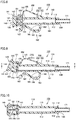
Fig. 5 is a schematic diagram showing the attached state where the plug is attached to the first opening end of the main body in the blood circuit connector shown inFig. 1 .Fig. 6 is a cross-sectional view taken along a line VI-VI shown inFig. 5. Fig. 7 is a cross-sectional view taken along a line VII-VII shown inFig. 6 . Referring toFigs. 5 to 7 , an explanation will be hereinafter given with regard to the attached state whereplug 140 is attached to first openingend 120 inblood circuit connector 100. - As shown in
Figs. 5 to 7 , in the attached state whereplug 140 is attached so as to close first openingend 120,bottom 141 ofplug 140 is disposed so as to face first openingend 120 in the extending direction of the axis line ofmain body 110, and first openingend 120 is housed inhousing space 144. - As shown in
Fig. 7 , in the state where first openingend 120 is housed inhousing space 144, a pair ofengagement parts 114 comes in contact with the inner side surface ofside wall 142, so thatplug 140 engages with first openingend 120. In this case, as shown inFig. 6 , a gap is provided between the inner circumferential surface of first openingend 120 and each of end 143a of positioningpart 143 and the inner side surface ofside wall 142, so thatside wall 142 ofplug 140 is loosely fitted to outercircumferential surface 111 of first openingend 120. - Furthermore, when
plug 140 is attached to first openingend 120,connection part 150 is flexibly deformed, and thus, plug 140 is attached to first openingend 120 while swinging against the elastic force generated by elasticforce generating part 156 such that the axis line ofplug 140 extends in line with the axis line ofmain body 110. Thereby, elasticforce generating part 156 maintains the state whereplug 140 is biased in the DR2 direction (seeFig. 2 ). -
Fig. 8 is a cross-sectional view showing the state where a tube is introduced into the other end of the blood circuit connector from the state shown inFig. 5 . Referring toFig. 8 , an explanation will be hereinafter given with regard to the state where atube 171 is introduced into the other end of the blood circuit connector. - As shown in
Fig. 8 , whenextracorporeal circulation circuit 1 is formed,blood circuit connector 100 is prepared, into whichtube 171 forming a part of artery-side blood circuit 20 (seeFig. 1 ) or vein-side blood circuit 30 (seeFig. 1 ) is inserted in advance through second openingend 130. In this state, plug 140 is attached to first openingend 120. It is to be noted thattube 171 is liquid-tightly inserted into throughhole 112. -
Fig. 9 is a cross-sectional view showing the manner in which the curved part of the connection part in the blood circuit connector is pushed to be moved from the state shown inFig. 8. Fig. 10 is a cross-sectional view taken along a line X-X shown inFig. 9 .Fig. 11 is a cross-sectional view showing the state where the plug is removed from the first opening end of the main body in the blood circuit connector. Referring toFigs. 9 to 11 , the operation for removingplug 140 from first openingend 120 will be hereinafter described. - As shown in
Fig. 9 , whenplug 140 is removed from first openingend 120,curved part 155 ofconnection part 150 is pushed in the direction approaching outercircumferential surface 111 ofmain body 110. In this case, the user uses his/her index finger or middle finger of one hand togrip hook 160 so as to be covered, and then, uses his/her thumb to pushcurved part 155 to be moved, for example, in a DR3 direction shown in the figure. Thereby,curved part 155 is extended, so thatplug 140 moves away fromhook 160 and swings in the direction back to the removed state (the DR2 direction: seeFig. 2 ). - While
plug 140 is swinging, plug 140 is inclined such that the end ofside wall 142 ofplug 140 is positioned in the manner in which its tip end on theconnection part 150 side is located closer tosecond opening end 130 than its tip end on thehook 160 side is. Between the inner side surface ofside wall 142 and outercircumferential surface 111 ofmain body 110, and betweenpositioning part 143 and the inner circumferential surface ofmain body 110, a gap is provided such thatplug 140 is swingable relative to first openingend 120. - In this state, as shown in
Fig. 10 , since a pair ofengagement parts 114 comes in contact with the inner side surface ofside wall 142 ofplug 140, the loosely fitted state betweenside wall 142 and first openingend 120 is not canceled. - When
curved part 155 ofconnection part 150 is further pushed with a thumb in the direction approaching outercircumferential surface 111 ofmain body 110 as described above,curved part 155 is further extended, so thatplug 140 swings to a position at which the pair ofengagement parts 114 does not come in contact with the inner side surface ofside wall 142 ofplug 140. Thereby, the loosely fitted state betweenside wall 142 ofplug 140 and first openingend 120 is cancelled. - As shown in
Fig. 11 , when the loosely fitted state betweenside wall 142 ofplug 140 and first openingend 120 is canceled, the restoring force obtained based on the elastic force generated by elasticforce generating part 156 causes plug 140 to further swing in the DR2 direction such thatplug 140 is moved away from above the axis line ofmain body 110. Thereby, plug 140 moves in the extending direction of the axis line of the main body to a position at which thisplug 140 does not overlap withmain body 110. - In this way, plug 140 can be readily removed from
main body 110 in a single-touch operation of pushingconnection part 150 in the direction approachingmain body 110. Since such a single-touch operation can be performed only with one hand, plug 140 can be removed more smoothly. Thus, it becomes possible to eliminate the time and effort caused when one hand is used to grip and removeplug 140 while using the other hand to fixmain body 110 as in the conventional case. -
Fig. 12 is a schematic diagram showing an example of the state where the blood circuit connector is used during a priming process. Referring toFig. 12 , an explanation will be hereinafter given with regard to an example of the state where the blood circuit connector is used during the priming process. - As shown in
Fig. 12 , in the state wheretube 171 is inserted through second openingend 130, and in the state whereplug 140 is removed from first openingend 120 ofmain body 110,hook 160 is hooked on anorifice 181 of acontainer 180 such that first openingend 120 faces the inside ofcontainer 180. - By hooking
blood circuit connector 100 oncontainer 180 so as to be attached thereto, the physiological saline and the like having circulated throughextracorporeal circulation circuit 1 can be discharged intocontainer 180. In addition, also when hemodialysis is completed,blood circuit connector 100 is attached to orifice 181 ofcontainer 180 as described above, so that the circulation liquid can be discharged. - In this way, when the physiological saline and the circulation liquid are discharged, plug 140 does not overlap with
main body 110 in the extending direction of the axis line of the main body, with the result that the physiological saline and the circulation liquid can be readily discharged through first openingend 120. - By the configuration as described above, in
blood circuit connector 100 according to the present embodiment,connection part 150 is pushed to be moved closer tomain body 110, so thatplug 140 can be readily removed from first openingend 120. Furthermore, an extracorporeal circulation circuit can be readily formed by usingblood circuit connector 100 according to the present embodiment. - As described above,
blood circuit connector 100 according to the present embodiment has been described while illustrating the configuration including elasticforce generating part 156, but the configuration not including elasticforce generating part 156 may be applied. Also in such a configuration,curved part 155 is coupled to the end on the outer side surface ofside wall 142 ofplug 140 that is located on the opposite side tobottom 141, so thatplug 140 can be readily removed from first openingend 120 while utilizing the elastic force caused by flexible deformation ofcurved part 155. - Although the embodiments of the present invention have been described as above, the embodiments disclosed herein are illustrative and non-restrictive in every respect. The scope of the present invention is defined by the terms of the claims, and is intended to include any modifications within the meaning and scope equivalent to the terms of the claims.
- 1 extracorporeal circulation circuit, 10 dialyzer, 20 artery-side blood circuit, 21, 31 clamp, 30 vein-side blood circuit, 40 artery-side drip chamber, 50 blood pump, 60 physiological-saline supply part, 70 artery-side puncture needle, 80 vein-side drip chamber, 90 vein-side puncture needle, 100 blood circuit connector, 110 main body, 111 outer circumferential surface, 112 through hole, 113 protrusion, 114, 115 engagement part, 120 first opening end, 121 first opening, 130 second opening end, 131 second opening, 140 plug, 141 bottom, 142 side wall, 143 positioning part, 143a end, 143b base part, 144 housing space, 150 connection part, 151 first fixed end, 152 second fixed end, 153 inclined part, 154 reinforcement part, 155 curved part, 156 elastic force generating part, 160 hook, 161 fixed end, 162 linear part, 163 curved part, 164 bent part, 165 reinforcement part, 167 free end, 171 tube.
Claims (4)
- A blood circuit connector (100) comprising;
a main body (110) having a cylindrical shape, the main body (110) having a through hole provided therein to have one end provided with a first opening end (120) and the other end provided with a second opening end (130);
a plug (140) having a bottomed cylindrical shape and detachably attached to the first opening end (120); and
a connection part (150) having flexibility and configured to connect the main body (110) and the plug (140),
the plug (140) including a side wall (142) loosely fitted to an outer circumferential surface (111) of the first opening end (120) and a bottom facing the first opening end (120) in an extending direction of an axis line of the main body (110) in an attached state where the plug (140) is attached to the first opening end (120),
the connection part (150) including a first fixed end connected to the side wall (142) of the plug (140), a second fixed end connected to an outer circumferential surface (111) of the main body (110), and a curved part located between the first fixed end and the second fixed end and expanding in a direction away from the main body (110), and
in the attached state, the curved part being pushed in a direction approaching the outer circumferential surface (111) of the main body (110) such that the curved part extends, to cancel a loosely fitted state between the side wall (142) of the plug (140) and the outer circumferential surface (111) of the first opening end (120), so as to remove the plug (140) from the first opening end (120). - The blood circuit connector (100) according to claim 1, wherein
the connection part (150) further includes an elastic force generating part located between the first fixed end and the curved part, and flexibly deformed in the attached state so as to generate elastic force,
the plug (140) is attached to the first opening end (120) as the plug (140) swings against the elastic force generated by the elastic force generating part such that an axis line of the plug (140) extends in line with the axis line of the main body (110), and
when the plug (140) is removed, the loosely fitted state between the side wall (142) of the plug (140) and the outer circumferential surface (111) of the first opening end (120) is cancelled, to cause the plug (140) to swing with restoring force produced based on the elastic force generated by the elastic force generating part, so as to move the plug (140) away from above the axis line of the main body (110). - The blood circuit connector (100) according to claim 2, wherein the elastic force generating part has an approximately S-shape.
- The blood circuit connector (100) according to any one of claims 1 to 3, wherein the main body (110), the plug (140) and the connection part (150) are integrally molded by injection molding.
Applications Claiming Priority (1)
| Application Number | Priority Date | Filing Date | Title |
|---|---|---|---|
| PCT/JP2014/066417 WO2015194032A1 (en) | 2014-06-20 | 2014-06-20 | Connector for blood circuit |
Publications (3)
| Publication Number | Publication Date |
|---|---|
| EP3159024A1 true EP3159024A1 (en) | 2017-04-26 |
| EP3159024A4 EP3159024A4 (en) | 2018-02-28 |
| EP3159024B1 EP3159024B1 (en) | 2025-05-14 |
Family
ID=54935061
Family Applications (1)
| Application Number | Title | Priority Date | Filing Date |
|---|---|---|---|
| EP14895308.6A Active EP3159024B1 (en) | 2014-06-20 | 2014-06-20 | Connector for blood circuit |
Country Status (5)
| Country | Link |
|---|---|
| US (1) | US10112037B2 (en) |
| EP (1) | EP3159024B1 (en) |
| JP (1) | JP6390704B2 (en) |
| CN (1) | CN106456858B (en) |
| WO (1) | WO2015194032A1 (en) |
Cited By (1)
| Publication number | Priority date | Publication date | Assignee | Title |
|---|---|---|---|---|
| WO2019011870A1 (en) * | 2017-07-10 | 2019-01-17 | Conceptomed As | Fluid transfer connectors |
Family Cites Families (16)
| Publication number | Priority date | Publication date | Assignee | Title |
|---|---|---|---|---|
| US3120879A (en) * | 1961-09-15 | 1964-02-11 | Gits Bros Mfg Co | Oil cup with integral spring |
| DE1432100A1 (en) * | 1961-10-07 | 1969-01-23 | Bross Dipl Ing Helmut | Pouring cap |
| JPS6137168A (en) | 1984-07-31 | 1986-02-22 | 川澄化学工業株式会社 | Body fluid treating circuit |
| US5385372A (en) | 1993-01-08 | 1995-01-31 | Utterberg; David S. | Luer connector with integral closure |
| IT1266389B1 (en) * | 1993-02-15 | 1996-12-30 | Alberto Degrassi | CONTAINER STRUCTURE, PARTICULARLY FOR CELL CULTURES |
| US6003556A (en) * | 1995-10-06 | 1999-12-21 | Cobe Laboratories, Inc. | Hinged cap fluid connector |
| US5951519A (en) * | 1997-04-25 | 1999-09-14 | Dsu Medical Corporation | Aseptic female connector |
| JP3881749B2 (en) | 1997-05-30 | 2007-02-14 | 日機装株式会社 | Shunt fitting cap |
| WO2003011206A1 (en) | 2001-07-31 | 2003-02-13 | Lh Medical Products, Inc. | Feeding tube spike set with integrated y-port |
| TWM293772U (en) * | 2005-11-10 | 2006-07-11 | Wu Pei Jen | Safety injection catheter |
| US9895526B2 (en) | 2006-03-08 | 2018-02-20 | Ivaxis, Llc | Anti-contamination cover for fluid connections |
| EP1996274B1 (en) | 2006-03-08 | 2016-09-14 | Dotted Intellectual Property LLC | Anti-contamination cover for fluid connections |
| JP5449869B2 (en) | 2009-06-03 | 2014-03-19 | 川澄化学工業株式会社 | Male shunt cap and extracorporeal circuit |
| JP5449934B2 (en) * | 2009-09-07 | 2014-03-19 | 川澄化学工業株式会社 | Shunt cap and extracorporeal circuit |
| US9480833B2 (en) * | 2010-07-15 | 2016-11-01 | Becton, Dickinson And Company | Antimicrobial IV access cap |
| CN202446549U (en) * | 2012-02-07 | 2012-09-26 | 姚建增 | Injection liquid drug puncture-free T-shaped tube assembly |
-
2014
- 2014-06-20 WO PCT/JP2014/066417 patent/WO2015194032A1/en not_active Ceased
- 2014-06-20 CN CN201480079986.4A patent/CN106456858B/en active Active
- 2014-06-20 EP EP14895308.6A patent/EP3159024B1/en active Active
- 2014-06-20 JP JP2016528750A patent/JP6390704B2/en active Active
- 2014-06-20 US US15/320,017 patent/US10112037B2/en active Active
Cited By (2)
| Publication number | Priority date | Publication date | Assignee | Title |
|---|---|---|---|---|
| WO2019011870A1 (en) * | 2017-07-10 | 2019-01-17 | Conceptomed As | Fluid transfer connectors |
| US11779746B2 (en) | 2017-07-10 | 2023-10-10 | Conceptomed As | Fluid transfer connectors |
Also Published As
| Publication number | Publication date |
|---|---|
| EP3159024A4 (en) | 2018-02-28 |
| CN106456858A (en) | 2017-02-22 |
| JP6390704B2 (en) | 2018-09-19 |
| WO2015194032A1 (en) | 2015-12-23 |
| EP3159024B1 (en) | 2025-05-14 |
| US10112037B2 (en) | 2018-10-30 |
| JPWO2015194032A1 (en) | 2017-04-20 |
| CN106456858B (en) | 2019-07-05 |
| US20170128711A1 (en) | 2017-05-11 |
Similar Documents
| Publication | Publication Date | Title |
|---|---|---|
| EP3124071A1 (en) | Connector and infusion set | |
| CN114828910B (en) | Locking connector | |
| JP2004305466A (en) | Medical connector set and indwelling catheter set using the same | |
| KR20110042304A (en) | Connector for disposable container to be used in dialysis machines | |
| CN106132296B (en) | Medical measuring system and method for producing the measuring system | |
| US10112037B2 (en) | Blood circuit connector | |
| US20200367987A1 (en) | Container Holder For A Dialysis Apparatus | |
| EP2404637A1 (en) | Disposable connector for hemofiltration | |
| JP6344944B2 (en) | Indwelling needle for extracorporeal circulation | |
| CN104334225B (en) | Indwelling needle device | |
| JP2014068711A (en) | Indwelling needle | |
| CA3123608C (en) | Sterilizable peritoneal dialysis connection device | |
| US20180099135A1 (en) | Medical fluid line connector | |
| JP4128451B2 (en) | Dialysis machine blood circulation circuit fitting | |
| JP2015188571A (en) | Cap for indwelling needle, extracorporeal circulation indwelling needle with cap, blood circuit, and priming method of blood circuit | |
| JP2018143864A (en) | Connector for blood circuit | |
| JP5262262B2 (en) | Indwelling needle device | |
| JPH0517072Y2 (en) | ||
| JPWO2018186495A1 (en) | Injection needle cap and dialysis circuit priming device | |
| JP2009089841A (en) | Indwelling needle connector | |
| JP4223167B2 (en) | Blood circuit | |
| KR101695451B1 (en) | Apparatus for connecting tube | |
| KR102520292B1 (en) | Catheter for intravenous injection | |
| JP2016154617A (en) | Indwelling needle device | |
| CN203694395U (en) | Safety infusion device capable of being connected with and separated from heparin cap rapidly |
Legal Events
| Date | Code | Title | Description |
|---|---|---|---|
| STAA | Information on the status of an ep patent application or granted ep patent |
Free format text: STATUS: THE INTERNATIONAL PUBLICATION HAS BEEN MADE |
|
| PUAI | Public reference made under article 153(3) epc to a published international application that has entered the european phase |
Free format text: ORIGINAL CODE: 0009012 |
|
| STAA | Information on the status of an ep patent application or granted ep patent |
Free format text: STATUS: REQUEST FOR EXAMINATION WAS MADE |
|
| 17P | Request for examination filed |
Effective date: 20161222 |
|
| AK | Designated contracting states |
Kind code of ref document: A1 Designated state(s): AL AT BE BG CH CY CZ DE DK EE ES FI FR GB GR HR HU IE IS IT LI LT LU LV MC MK MT NL NO PL PT RO RS SE SI SK SM TR |
|
| AX | Request for extension of the european patent |
Extension state: BA ME |
|
| DAX | Request for extension of the european patent (deleted) | ||
| A4 | Supplementary search report drawn up and despatched |
Effective date: 20180126 |
|
| RIC1 | Information provided on ipc code assigned before grant |
Ipc: A61M 1/36 20060101ALI20180122BHEP Ipc: A61M 1/14 20060101AFI20180122BHEP Ipc: A61M 39/12 20060101ALI20180122BHEP Ipc: A61M 39/28 20060101ALI20180122BHEP |
|
| STAA | Information on the status of an ep patent application or granted ep patent |
Free format text: STATUS: EXAMINATION IS IN PROGRESS |
|
| 17Q | First examination report despatched |
Effective date: 20220527 |
|
| GRAP | Despatch of communication of intention to grant a patent |
Free format text: ORIGINAL CODE: EPIDOSNIGR1 |
|
| STAA | Information on the status of an ep patent application or granted ep patent |
Free format text: STATUS: GRANT OF PATENT IS INTENDED |
|
| INTG | Intention to grant announced |
Effective date: 20241205 |
|
| GRAS | Grant fee paid |
Free format text: ORIGINAL CODE: EPIDOSNIGR3 |
|
| GRAA | (expected) grant |
Free format text: ORIGINAL CODE: 0009210 |
|
| STAA | Information on the status of an ep patent application or granted ep patent |
Free format text: STATUS: THE PATENT HAS BEEN GRANTED |
|
| AK | Designated contracting states |
Kind code of ref document: B1 Designated state(s): AL AT BE BG CH CY CZ DE DK EE ES FI FR GB GR HR HU IE IS IT LI LT LU LV MC MK MT NL NO PL PT RO RS SE SI SK SM TR |
|
| REG | Reference to a national code |
Ref country code: GB Ref legal event code: FG4D |
|
| REG | Reference to a national code |
Ref country code: CH Ref legal event code: EP |
|
| REG | Reference to a national code |
Ref country code: IE Ref legal event code: FG4D |
|
| REG | Reference to a national code |
Ref country code: DE Ref legal event code: R096 Ref document number: 602014091938 Country of ref document: DE |
|
| REG | Reference to a national code |
Ref country code: NL Ref legal event code: MP Effective date: 20250514 |
|
| PG25 | Lapsed in a contracting state [announced via postgrant information from national office to epo] |
Ref country code: FI Free format text: LAPSE BECAUSE OF FAILURE TO SUBMIT A TRANSLATION OF THE DESCRIPTION OR TO PAY THE FEE WITHIN THE PRESCRIBED TIME-LIMIT Effective date: 20250514 Ref country code: ES Free format text: LAPSE BECAUSE OF FAILURE TO SUBMIT A TRANSLATION OF THE DESCRIPTION OR TO PAY THE FEE WITHIN THE PRESCRIBED TIME-LIMIT Effective date: 20250514 Ref country code: PT Free format text: LAPSE BECAUSE OF FAILURE TO SUBMIT A TRANSLATION OF THE DESCRIPTION OR TO PAY THE FEE WITHIN THE PRESCRIBED TIME-LIMIT Effective date: 20250915 |
|
| REG | Reference to a national code |
Ref country code: LT Ref legal event code: MG9D |
|
| PG25 | Lapsed in a contracting state [announced via postgrant information from national office to epo] |
Ref country code: GR Free format text: LAPSE BECAUSE OF FAILURE TO SUBMIT A TRANSLATION OF THE DESCRIPTION OR TO PAY THE FEE WITHIN THE PRESCRIBED TIME-LIMIT Effective date: 20250815 Ref country code: NO Free format text: LAPSE BECAUSE OF FAILURE TO SUBMIT A TRANSLATION OF THE DESCRIPTION OR TO PAY THE FEE WITHIN THE PRESCRIBED TIME-LIMIT Effective date: 20250814 |
|
| PG25 | Lapsed in a contracting state [announced via postgrant information from national office to epo] |
Ref country code: NL Free format text: LAPSE BECAUSE OF FAILURE TO SUBMIT A TRANSLATION OF THE DESCRIPTION OR TO PAY THE FEE WITHIN THE PRESCRIBED TIME-LIMIT Effective date: 20250514 Ref country code: PL Free format text: LAPSE BECAUSE OF FAILURE TO SUBMIT A TRANSLATION OF THE DESCRIPTION OR TO PAY THE FEE WITHIN THE PRESCRIBED TIME-LIMIT Effective date: 20250514 |
|
| REG | Reference to a national code |
Ref country code: AT Ref legal event code: MK05 Ref document number: 1794291 Country of ref document: AT Kind code of ref document: T Effective date: 20250514 |
|
| PG25 | Lapsed in a contracting state [announced via postgrant information from national office to epo] |
Ref country code: BG Free format text: LAPSE BECAUSE OF FAILURE TO SUBMIT A TRANSLATION OF THE DESCRIPTION OR TO PAY THE FEE WITHIN THE PRESCRIBED TIME-LIMIT Effective date: 20250514 |
|
| PG25 | Lapsed in a contracting state [announced via postgrant information from national office to epo] |
Ref country code: HR Free format text: LAPSE BECAUSE OF FAILURE TO SUBMIT A TRANSLATION OF THE DESCRIPTION OR TO PAY THE FEE WITHIN THE PRESCRIBED TIME-LIMIT Effective date: 20250514 |
|
| PG25 | Lapsed in a contracting state [announced via postgrant information from national office to epo] |
Ref country code: AT Free format text: LAPSE BECAUSE OF FAILURE TO SUBMIT A TRANSLATION OF THE DESCRIPTION OR TO PAY THE FEE WITHIN THE PRESCRIBED TIME-LIMIT Effective date: 20250514 |
|
| PG25 | Lapsed in a contracting state [announced via postgrant information from national office to epo] |
Ref country code: RS Free format text: LAPSE BECAUSE OF FAILURE TO SUBMIT A TRANSLATION OF THE DESCRIPTION OR TO PAY THE FEE WITHIN THE PRESCRIBED TIME-LIMIT Effective date: 20250814 |
|
| PG25 | Lapsed in a contracting state [announced via postgrant information from national office to epo] |
Ref country code: IS Free format text: LAPSE BECAUSE OF FAILURE TO SUBMIT A TRANSLATION OF THE DESCRIPTION OR TO PAY THE FEE WITHIN THE PRESCRIBED TIME-LIMIT Effective date: 20250914 |
|
| PG25 | Lapsed in a contracting state [announced via postgrant information from national office to epo] |
Ref country code: LV Free format text: LAPSE BECAUSE OF FAILURE TO SUBMIT A TRANSLATION OF THE DESCRIPTION OR TO PAY THE FEE WITHIN THE PRESCRIBED TIME-LIMIT Effective date: 20250514 |
|
| PG25 | Lapsed in a contracting state [announced via postgrant information from national office to epo] |
Ref country code: SM Free format text: LAPSE BECAUSE OF FAILURE TO SUBMIT A TRANSLATION OF THE DESCRIPTION OR TO PAY THE FEE WITHIN THE PRESCRIBED TIME-LIMIT Effective date: 20250514 Ref country code: DK Free format text: LAPSE BECAUSE OF FAILURE TO SUBMIT A TRANSLATION OF THE DESCRIPTION OR TO PAY THE FEE WITHIN THE PRESCRIBED TIME-LIMIT Effective date: 20250514 |
|
| PG25 | Lapsed in a contracting state [announced via postgrant information from national office to epo] |
Ref country code: CZ Free format text: LAPSE BECAUSE OF FAILURE TO SUBMIT A TRANSLATION OF THE DESCRIPTION OR TO PAY THE FEE WITHIN THE PRESCRIBED TIME-LIMIT Effective date: 20250514 |
|
| PG25 | Lapsed in a contracting state [announced via postgrant information from national office to epo] |
Ref country code: EE Free format text: LAPSE BECAUSE OF FAILURE TO SUBMIT A TRANSLATION OF THE DESCRIPTION OR TO PAY THE FEE WITHIN THE PRESCRIBED TIME-LIMIT Effective date: 20250514 |
|
| PG25 | Lapsed in a contracting state [announced via postgrant information from national office to epo] |
Ref country code: RO Free format text: LAPSE BECAUSE OF FAILURE TO SUBMIT A TRANSLATION OF THE DESCRIPTION OR TO PAY THE FEE WITHIN THE PRESCRIBED TIME-LIMIT Effective date: 20250514 Ref country code: SK Free format text: LAPSE BECAUSE OF FAILURE TO SUBMIT A TRANSLATION OF THE DESCRIPTION OR TO PAY THE FEE WITHIN THE PRESCRIBED TIME-LIMIT Effective date: 20250514 |
|
| REG | Reference to a national code |
Ref country code: CH Ref legal event code: H13 Free format text: ST27 STATUS EVENT CODE: U-0-0-H10-H13 (AS PROVIDED BY THE NATIONAL OFFICE) Effective date: 20260127 |
|
| PG25 | Lapsed in a contracting state [announced via postgrant information from national office to epo] |
Ref country code: IT Free format text: LAPSE BECAUSE OF FAILURE TO SUBMIT A TRANSLATION OF THE DESCRIPTION OR TO PAY THE FEE WITHIN THE PRESCRIBED TIME-LIMIT Effective date: 20250514 |
|
| PG25 | Lapsed in a contracting state [announced via postgrant information from national office to epo] |
Ref country code: LU Free format text: LAPSE BECAUSE OF NON-PAYMENT OF DUE FEES Effective date: 20250620 |
|
| REG | Reference to a national code |
Ref country code: DE Ref legal event code: R097 Ref document number: 602014091938 Country of ref document: DE |
|
| PG25 | Lapsed in a contracting state [announced via postgrant information from national office to epo] |
Ref country code: MC Free format text: LAPSE BECAUSE OF FAILURE TO SUBMIT A TRANSLATION OF THE DESCRIPTION OR TO PAY THE FEE WITHIN THE PRESCRIBED TIME-LIMIT Effective date: 20250514 |
|
| REG | Reference to a national code |
Ref country code: BE Ref legal event code: MM Effective date: 20250630 |
|
| PLBE | No opposition filed within time limit |
Free format text: ORIGINAL CODE: 0009261 |
|
| STAA | Information on the status of an ep patent application or granted ep patent |
Free format text: STATUS: NO OPPOSITION FILED WITHIN TIME LIMIT |
|
| REG | Reference to a national code |
Ref country code: CH Ref legal event code: L10 Free format text: ST27 STATUS EVENT CODE: U-0-0-L10-L00 (AS PROVIDED BY THE NATIONAL OFFICE) Effective date: 20260325 |
|
| PG25 | Lapsed in a contracting state [announced via postgrant information from national office to epo] |
Ref country code: IE Free format text: LAPSE BECAUSE OF NON-PAYMENT OF DUE FEES Effective date: 20250620 |
|
| PG25 | Lapsed in a contracting state [announced via postgrant information from national office to epo] |
Ref country code: BE Free format text: LAPSE BECAUSE OF NON-PAYMENT OF DUE FEES Effective date: 20250630 |
|
| PG25 | Lapsed in a contracting state [announced via postgrant information from national office to epo] |
Ref country code: FR Free format text: LAPSE BECAUSE OF NON-PAYMENT OF DUE FEES Effective date: 20250714 |
|
| 26N | No opposition filed |
Effective date: 20260217 |
|
| PG25 | Lapsed in a contracting state [announced via postgrant information from national office to epo] |
Ref country code: CH Free format text: LAPSE BECAUSE OF NON-PAYMENT OF DUE FEES Effective date: 20250630 |
|
| GBPC | Gb: european patent ceased through non-payment of renewal fee |
Effective date: 20250814 |
|
| PG25 | Lapsed in a contracting state [announced via postgrant information from national office to epo] |
Ref country code: LT Free format text: LAPSE BECAUSE OF FAILURE TO SUBMIT A TRANSLATION OF THE DESCRIPTION OR TO PAY THE FEE WITHIN THE PRESCRIBED TIME-LIMIT Effective date: 20250514 |
|
| PG25 | Lapsed in a contracting state [announced via postgrant information from national office to epo] |
Ref country code: GB Free format text: LAPSE BECAUSE OF NON-PAYMENT OF DUE FEES Effective date: 20250814 |
|
| PGFP | Annual fee paid to national office [announced via postgrant information from national office to epo] |
Ref country code: DE Payment date: 20260622 Year of fee payment: 13 |
|
| PG25 | Lapsed in a contracting state [announced via postgrant information from national office to epo] |
Ref country code: CY Free format text: LAPSE BECAUSE OF FAILURE TO SUBMIT A TRANSLATION OF THE DESCRIPTION OR TO PAY THE FEE WITHIN THE PRESCRIBED TIME-LIMIT Effective date: 20250514 Ref country code: SE Free format text: LAPSE BECAUSE OF FAILURE TO SUBMIT A TRANSLATION OF THE DESCRIPTION OR TO PAY THE FEE WITHIN THE PRESCRIBED TIME-LIMIT Effective date: 20250514 |