EP3158955A1 - Forceps device and surgical system - Google Patents
Forceps device and surgical system Download PDFInfo
- Publication number
- EP3158955A1 EP3158955A1 EP15809916.8A EP15809916A EP3158955A1 EP 3158955 A1 EP3158955 A1 EP 3158955A1 EP 15809916 A EP15809916 A EP 15809916A EP 3158955 A1 EP3158955 A1 EP 3158955A1
- Authority
- EP
- European Patent Office
- Prior art keywords
- motive
- gripping pieces
- pair
- gripping
- forceps device
- Prior art date
- Legal status (The legal status is an assumption and is not a legal conclusion. Google has not performed a legal analysis and makes no representation as to the accuracy of the status listed.)
- Withdrawn
Links
- 230000007246 mechanism Effects 0.000 claims abstract description 51
- 230000033001 locomotion Effects 0.000 claims abstract description 29
- 230000037361 pathway Effects 0.000 claims abstract description 6
- 238000005452 bending Methods 0.000 claims description 32
- 239000003989 dielectric material Substances 0.000 claims description 9
- 238000003780 insertion Methods 0.000 claims description 7
- 230000037431 insertion Effects 0.000 claims description 7
- 238000001514 detection method Methods 0.000 claims description 4
- 230000002439 hemostatic effect Effects 0.000 description 16
- 238000010586 diagram Methods 0.000 description 13
- 230000002093 peripheral effect Effects 0.000 description 10
- 230000000740 bleeding effect Effects 0.000 description 9
- 238000000034 method Methods 0.000 description 8
- 230000004048 modification Effects 0.000 description 7
- 238000012986 modification Methods 0.000 description 7
- 230000008901 benefit Effects 0.000 description 5
- 229910052751 metal Inorganic materials 0.000 description 5
- 239000002184 metal Substances 0.000 description 5
- 230000023597 hemostasis Effects 0.000 description 4
- 238000009413 insulation Methods 0.000 description 4
- 229920001343 polytetrafluoroethylene Polymers 0.000 description 4
- 239000004810 polytetrafluoroethylene Substances 0.000 description 4
- 239000004020 conductor Substances 0.000 description 3
- 210000002429 large intestine Anatomy 0.000 description 3
- 239000004696 Poly ether ether ketone Substances 0.000 description 2
- 230000015271 coagulation Effects 0.000 description 2
- 238000005345 coagulation Methods 0.000 description 2
- 238000010292 electrical insulation Methods 0.000 description 2
- 239000012212 insulator Substances 0.000 description 2
- 239000000463 material Substances 0.000 description 2
- 229920002530 polyetherether ketone Polymers 0.000 description 2
- RTAQQCXQSZGOHL-UHFFFAOYSA-N Titanium Chemical compound [Ti] RTAQQCXQSZGOHL-UHFFFAOYSA-N 0.000 description 1
- PNEYBMLMFCGWSK-UHFFFAOYSA-N aluminium oxide Inorganic materials [O-2].[O-2].[O-2].[Al+3].[Al+3] PNEYBMLMFCGWSK-UHFFFAOYSA-N 0.000 description 1
- 210000000436 anus Anatomy 0.000 description 1
- 239000000919 ceramic Substances 0.000 description 1
- 230000001112 coagulating effect Effects 0.000 description 1
- 238000006073 displacement reaction Methods 0.000 description 1
- 230000000694 effects Effects 0.000 description 1
- 238000010336 energy treatment Methods 0.000 description 1
- TWNQGVIAIRXVLR-UHFFFAOYSA-N oxo(oxoalumanyloxy)alumane Chemical compound O=[Al]O[Al]=O TWNQGVIAIRXVLR-UHFFFAOYSA-N 0.000 description 1
- 239000004033 plastic Substances 0.000 description 1
- 239000004417 polycarbonate Substances 0.000 description 1
- 229920000515 polycarbonate Polymers 0.000 description 1
- -1 polytetrafluoroethylene Polymers 0.000 description 1
- 230000004044 response Effects 0.000 description 1
- 230000000284 resting effect Effects 0.000 description 1
- 229920002050 silicone resin Polymers 0.000 description 1
- 229910001220 stainless steel Inorganic materials 0.000 description 1
- 239000010935 stainless steel Substances 0.000 description 1
- 238000001356 surgical procedure Methods 0.000 description 1
- 239000010936 titanium Substances 0.000 description 1
- 229910052719 titanium Inorganic materials 0.000 description 1
- WFKWXMTUELFFGS-UHFFFAOYSA-N tungsten Chemical compound [W] WFKWXMTUELFFGS-UHFFFAOYSA-N 0.000 description 1
- 229910052721 tungsten Inorganic materials 0.000 description 1
- 239000010937 tungsten Substances 0.000 description 1
Images







Classifications
-
- A—HUMAN NECESSITIES
- A61—MEDICAL OR VETERINARY SCIENCE; HYGIENE
- A61B—DIAGNOSIS; SURGERY; IDENTIFICATION
- A61B17/00—Surgical instruments, devices or methods
- A61B17/28—Surgical forceps
- A61B17/29—Forceps for use in minimally invasive surgery
-
- A—HUMAN NECESSITIES
- A61—MEDICAL OR VETERINARY SCIENCE; HYGIENE
- A61B—DIAGNOSIS; SURGERY; IDENTIFICATION
- A61B1/00—Instruments for performing medical examinations of the interior of cavities or tubes of the body by visual or photographical inspection, e.g. endoscopes; Illuminating arrangements therefor
- A61B1/00131—Accessories for endoscopes
- A61B1/00133—Drive units for endoscopic tools inserted through or with the endoscope
-
- A—HUMAN NECESSITIES
- A61—MEDICAL OR VETERINARY SCIENCE; HYGIENE
- A61B—DIAGNOSIS; SURGERY; IDENTIFICATION
- A61B1/00—Instruments for performing medical examinations of the interior of cavities or tubes of the body by visual or photographical inspection, e.g. endoscopes; Illuminating arrangements therefor
- A61B1/012—Instruments for performing medical examinations of the interior of cavities or tubes of the body by visual or photographical inspection, e.g. endoscopes; Illuminating arrangements therefor characterised by internal passages or accessories therefor
- A61B1/018—Instruments for performing medical examinations of the interior of cavities or tubes of the body by visual or photographical inspection, e.g. endoscopes; Illuminating arrangements therefor characterised by internal passages or accessories therefor for receiving instruments
-
- A—HUMAN NECESSITIES
- A61—MEDICAL OR VETERINARY SCIENCE; HYGIENE
- A61B—DIAGNOSIS; SURGERY; IDENTIFICATION
- A61B18/00—Surgical instruments, devices or methods for transferring non-mechanical forms of energy to or from the body
- A61B18/04—Surgical instruments, devices or methods for transferring non-mechanical forms of energy to or from the body by heating
- A61B18/08—Surgical instruments, devices or methods for transferring non-mechanical forms of energy to or from the body by heating by means of electrically-heated probes
- A61B18/082—Probes or electrodes therefor
- A61B18/085—Forceps, scissors
-
- A—HUMAN NECESSITIES
- A61—MEDICAL OR VETERINARY SCIENCE; HYGIENE
- A61B—DIAGNOSIS; SURGERY; IDENTIFICATION
- A61B18/00—Surgical instruments, devices or methods for transferring non-mechanical forms of energy to or from the body
- A61B18/04—Surgical instruments, devices or methods for transferring non-mechanical forms of energy to or from the body by heating
- A61B18/12—Surgical instruments, devices or methods for transferring non-mechanical forms of energy to or from the body by heating by passing a current through the tissue to be heated, e.g. high-frequency current
- A61B18/14—Probes or electrodes therefor
- A61B18/1442—Probes having pivoting end effectors, e.g. forceps
-
- A—HUMAN NECESSITIES
- A61—MEDICAL OR VETERINARY SCIENCE; HYGIENE
- A61B—DIAGNOSIS; SURGERY; IDENTIFICATION
- A61B18/00—Surgical instruments, devices or methods for transferring non-mechanical forms of energy to or from the body
- A61B18/04—Surgical instruments, devices or methods for transferring non-mechanical forms of energy to or from the body by heating
- A61B18/12—Surgical instruments, devices or methods for transferring non-mechanical forms of energy to or from the body by heating by passing a current through the tissue to be heated, e.g. high-frequency current
- A61B18/14—Probes or electrodes therefor
- A61B18/1492—Probes or electrodes therefor having a flexible, catheter-like structure, e.g. for heart ablation
-
- A—HUMAN NECESSITIES
- A61—MEDICAL OR VETERINARY SCIENCE; HYGIENE
- A61B—DIAGNOSIS; SURGERY; IDENTIFICATION
- A61B1/00—Instruments for performing medical examinations of the interior of cavities or tubes of the body by visual or photographical inspection, e.g. endoscopes; Illuminating arrangements therefor
- A61B1/00064—Constructional details of the endoscope body
- A61B1/00071—Insertion part of the endoscope body
- A61B1/0008—Insertion part of the endoscope body characterised by distal tip features
- A61B1/00098—Deflecting means for inserted tools
-
- A—HUMAN NECESSITIES
- A61—MEDICAL OR VETERINARY SCIENCE; HYGIENE
- A61B—DIAGNOSIS; SURGERY; IDENTIFICATION
- A61B17/00—Surgical instruments, devices or methods
- A61B17/00234—Surgical instruments, devices or methods for minimally invasive surgery
- A61B2017/00292—Surgical instruments, devices or methods for minimally invasive surgery mounted on or guided by flexible, e.g. catheter-like, means
- A61B2017/003—Steerable
-
- A—HUMAN NECESSITIES
- A61—MEDICAL OR VETERINARY SCIENCE; HYGIENE
- A61B—DIAGNOSIS; SURGERY; IDENTIFICATION
- A61B17/00—Surgical instruments, devices or methods
- A61B2017/00367—Details of actuation of instruments, e.g. relations between pushing buttons, or the like, and activation of the tool, working tip, or the like
- A61B2017/00398—Details of actuation of instruments, e.g. relations between pushing buttons, or the like, and activation of the tool, working tip, or the like using powered actuators, e.g. stepper motors, solenoids
-
- A—HUMAN NECESSITIES
- A61—MEDICAL OR VETERINARY SCIENCE; HYGIENE
- A61B—DIAGNOSIS; SURGERY; IDENTIFICATION
- A61B17/00—Surgical instruments, devices or methods
- A61B17/28—Surgical forceps
- A61B17/29—Forceps for use in minimally invasive surgery
- A61B2017/2901—Details of shaft
- A61B2017/2902—Details of shaft characterized by features of the actuating rod
- A61B2017/2903—Details of shaft characterized by features of the actuating rod transferring rotary motion
-
- A—HUMAN NECESSITIES
- A61—MEDICAL OR VETERINARY SCIENCE; HYGIENE
- A61B—DIAGNOSIS; SURGERY; IDENTIFICATION
- A61B18/00—Surgical instruments, devices or methods for transferring non-mechanical forms of energy to or from the body
- A61B2018/00053—Mechanical features of the instrument of device
- A61B2018/00059—Material properties
- A61B2018/00071—Electrical conductivity
- A61B2018/00077—Electrical conductivity high, i.e. electrically conducting
-
- A—HUMAN NECESSITIES
- A61—MEDICAL OR VETERINARY SCIENCE; HYGIENE
- A61B—DIAGNOSIS; SURGERY; IDENTIFICATION
- A61B18/00—Surgical instruments, devices or methods for transferring non-mechanical forms of energy to or from the body
- A61B2018/00053—Mechanical features of the instrument of device
- A61B2018/00059—Material properties
- A61B2018/00071—Electrical conductivity
- A61B2018/00083—Electrical conductivity low, i.e. electrically insulating
-
- A—HUMAN NECESSITIES
- A61—MEDICAL OR VETERINARY SCIENCE; HYGIENE
- A61B—DIAGNOSIS; SURGERY; IDENTIFICATION
- A61B18/00—Surgical instruments, devices or methods for transferring non-mechanical forms of energy to or from the body
- A61B2018/00053—Mechanical features of the instrument of device
- A61B2018/00172—Connectors and adapters therefor
- A61B2018/00178—Electrical connectors
-
- A—HUMAN NECESSITIES
- A61—MEDICAL OR VETERINARY SCIENCE; HYGIENE
- A61B—DIAGNOSIS; SURGERY; IDENTIFICATION
- A61B18/00—Surgical instruments, devices or methods for transferring non-mechanical forms of energy to or from the body
- A61B2018/00571—Surgical instruments, devices or methods for transferring non-mechanical forms of energy to or from the body for achieving a particular surgical effect
- A61B2018/00589—Coagulation
-
- A—HUMAN NECESSITIES
- A61—MEDICAL OR VETERINARY SCIENCE; HYGIENE
- A61B—DIAGNOSIS; SURGERY; IDENTIFICATION
- A61B18/00—Surgical instruments, devices or methods for transferring non-mechanical forms of energy to or from the body
- A61B2018/00571—Surgical instruments, devices or methods for transferring non-mechanical forms of energy to or from the body for achieving a particular surgical effect
- A61B2018/00601—Cutting
-
- A—HUMAN NECESSITIES
- A61—MEDICAL OR VETERINARY SCIENCE; HYGIENE
- A61B—DIAGNOSIS; SURGERY; IDENTIFICATION
- A61B18/00—Surgical instruments, devices or methods for transferring non-mechanical forms of energy to or from the body
- A61B2018/00982—Surgical instruments, devices or methods for transferring non-mechanical forms of energy to or from the body combined with or comprising means for visual or photographic inspections inside the body, e.g. endoscopes
-
- A—HUMAN NECESSITIES
- A61—MEDICAL OR VETERINARY SCIENCE; HYGIENE
- A61B—DIAGNOSIS; SURGERY; IDENTIFICATION
- A61B18/00—Surgical instruments, devices or methods for transferring non-mechanical forms of energy to or from the body
- A61B18/04—Surgical instruments, devices or methods for transferring non-mechanical forms of energy to or from the body by heating
- A61B18/12—Surgical instruments, devices or methods for transferring non-mechanical forms of energy to or from the body by heating by passing a current through the tissue to be heated, e.g. high-frequency current
- A61B18/14—Probes or electrodes therefor
- A61B2018/1405—Electrodes having a specific shape
-
- A—HUMAN NECESSITIES
- A61—MEDICAL OR VETERINARY SCIENCE; HYGIENE
- A61B—DIAGNOSIS; SURGERY; IDENTIFICATION
- A61B90/00—Instruments, implements or accessories specially adapted for surgery or diagnosis and not covered by any of the groups A61B1/00 - A61B50/00, e.g. for luxation treatment or for protecting wound edges
- A61B90/06—Measuring instruments not otherwise provided for
- A61B2090/064—Measuring instruments not otherwise provided for for measuring force, pressure or mechanical tension
- A61B2090/065—Measuring instruments not otherwise provided for for measuring force, pressure or mechanical tension for measuring contact or contact pressure
Definitions
- the present invention relates to a forceps device and a surgical system.
- gripping forceps that are provided with: a pair of gripping pieces; a cylindrical sheath in which the pair of gripping pieces at the distal end thereof; a driving system provided at the base end of the sheath; and manipulation wires that connect the gripping pieces and the driving system and that open/close the pair of gripping pieces by manually or electrically pushing and pulling the manipulation wires by means of the driving system (for example, see Patent Literature 1).
- a bleeding point is pinched by using metal tweezers, and an electric scalpel is brought into contact with the tweezers to supply a high-frequency current to the tweezers from the electric scalpel, thus coagulating tissue around the bleeding point by means of heat.
- the operation of the gripping forceps and peripheral equipment may be affected by the high-frequency current also flowing into the electric motors and the control system.
- electrical systems of peripheral devices that are used together with the gripping forceps such as an image-acquisition element or the like of an endoscope into which the gripping forceps are inserted, may be affected by noise or the like.
- the present invention has been conceived in light of the above-described circumstances, and an object thereof is to provide a forceps device that can also suitably be used as high-frequency hemostatic forceps by externally supplying a high-frequency current thereto, and to provide a surgical system provided with the same.
- the present invention provides the following solutions.
- a first aspect of the present invention is a forceps device including: an elongated body portion; a pair of gripping pieces that are provided at a distal end of the body portion, at least one of which possesses conductivity, and that can be opened/closed relative to each other; a motive-power output portion that is provided at a base end of the body portion and that outputs motive power; a motive-power converting mechanism that connects the pair of gripping pieces and the motive-power output portion, and that converts the motive power output by the motive-power output portion into relative opening/closing motions of the pair of gripping pieces; and an insulating member that is provided in a pathway connecting the pair of gripping pieces and the motive-power output portion via the motive-power converting mechanism, and that electrically insulates the pair of gripping pieces and the motive-power output portion from each other.
- the first aspect of the present invention by externally supplying a high-frequency current to at least one of the pair of gripping pieces, gripping a bleeding point, by using a high-frequency treatment device such as an electric scalpel, it is possible to achieve hemostasis by causing heat coagulation in tissue around the bleeding point between the pair of gripping pieces.
- the pair of gripping pieces are connected to the motive-power output portion via the motive-power converting mechanism for opening/closing them. Because the insulating member is provided on the pathway that connects the pair of gripping pieces and the motive-power output portion, the high-frequency current supplied to the gripping pieces does not reach the motive-power output portion. Therefore, even in the case in which an electric motor is employed as the motive-power output portion or in the case in which peripheral equipment is electrically connected via the motive-power output portion, the electric motor or the peripheral equipment is actuated without being affected by the high-frequency current.
- the present invention can suitably be used not only as gripping forceps but also as high-frequency hemostatic forceps. Note that the above-described "pathway " includes the pair of gripping pieces.
- the insulating member may be at least one of a plurality of components constituting the motive-power converting mechanism.
- the motive-power converting mechanism is provided with: a manipulation wire that is placed along a longitudinal direction in the body portion and that is made to undergo linear motions in the longitudinal direction by means of the motive power output by the motive-power output portion; and a linkage mechanism that connects the manipulation wire and the pair of gripping pieces and that converts the linear motions of the manipulation wire into the relative opening/closing motions of the pair of gripping pieces, wherein the insulating member is provided between the manipulation wire and the linkage mechanism to couple the manipulation wire and the linkage mechanism.
- the insulating member may be a second one of the gripping pieces formed of an electric insulator, and the motive-power converting mechanism is connected with the said second gripping piece, and causes the second gripping piece to undergo opening/closing motions with respect to a first one of the gripping pieces.
- the hemostatic treatment when performing the hemostatic treatment, by supplying a high-frequency current to the first gripping pieces in a state in which a hemostatic point is gripped with the pair of gripping pieces so that the second gripping piece is placed adjacent to the peripheral tissue, it is possible to protect the peripheral tissue other than the hemostatic point from the high-frequency current.
- the second gripping piece that serves as an insulating member is interposed between the motive-power converting mechanism and the first gripping piece, the high-frequency current supplied to the first gripping piece does not reach the motive-power converting mechanism.
- the body portion may be provided with a cylindrical sheath that accommodates the motive-power converting mechanism and that possesses electrical insulating properties.
- the above-described first aspect may include an electric contact portion that is provided at an intermediate position in a longitudinal direction of the sheath so as to be exposed at an exterior of the sheath, and that is electrically connected with the gripping pieces by passing through an interior of the sheath.
- the sheath may have, at an outer circumferential surface thereof, a slit that allows a portion, which is electrically connected with the pair of gripping pieces, of the motive-power converting mechanism to be exposed at the exterior, and the electric contact portion may be constituted of the portion of the motive-power converting mechanism.
- the electric contact portion is provided inside the sheath, it is possible to prevent the high-frequency treatment device from coming into contact with the tissue when supplying the high-frequency current.
- the position of an electrode or the like of the high-frequency device inserted into the slit is stabilized, it is possible to stably maintain the electrical connection.
- the electric contact portion may be constituted of a member that is secured to an outer circumferential surface of the sheath and that possesses conductivity.
- the body portion may be provided with, at a distal end thereof, a movable portion that can be bent or flexed about an axis that intersects the longitudinal axis of the body portion, and the electric contact portion may be provided farther on a base-end side than the movable portion is.
- a second aspect of the present invention is a surgical system including: any one of forceps devices described above; a high-frequency treatment device that includes an elongated body portion, and an electrode provided at a distal end of the body portion, and that discharges a high-frequency current; an endoscope that has two treatment-tool channels into which the forceps device and the high-frequency treatment device are individually inserted; and a contact means for placing the pair of gripping pieces and the electrode, which protrude from a distal-end surface of the endoscope via the treatment-tool channels, at positions at which mutual electrical connections are established therebetween.
- the electrode is brought into contact with, by means of the contact means, the pair of gripping pieces gripping the bleeding point, and the high-frequency current is supplied to the gripping pieces from the electrode, and thus, it is possible to achieve hemostasis by causing heat coagulation in the tissue around the bleeding point between the pair of gripping pieces.
- the gripping forceps as high-frequency hemostatic forceps.
- the high-frequency treatment device may be provided with, between the electrode and the body portion, a joint portion that can be flexed, and the contact means may be constituted of the joint portion.
- distal-end portions of the two treatment-tool channels may be inclined at angles that make extensions thereof intersect each other, and the contact means may be constituted of the distal-end portions of the two treatment-tool channels.
- the endoscope may be provided with, in the vicinity of the distal end thereof, arms that individually have arm channels that communicate with the two treatment-tool channels and bending portions that can be bent, and the contact means may be constituted of the bending portions of the arms.
- the above-described second aspect may be provided with a manipulation input device that is manipulated by an operator; and a control portion that controls the forceps device and the high-frequency treatment device in accordance with manipulations input via the manipulation input device.
- the above-described second aspect may be provided with a contact-detecting portion that detects an electrical contact between the pair of gripping pieces and the electrode, wherein the control portion controls at least one of the forceps device and the high-frequency treatment device on the basis of detection results of the contact-detecting portion.
- the contact-detecting portion it is possible, by means of the contact-detecting portion, to automatically detect whether or not the hemostatic manipulations are performed on the basis of the presence/absence of electrical contact between the gripping pieces and the electrode, and it is possible to operate the forceps device and the high-frequency treatment device in accordance with different settings between during the hemostatic manipulations and during other manipulations.
- the endoscope may be provided with a cylindrical cover member that externally extends from an insertion opening of the treatment-tool channel into which the forceps device is inserted, and the cover member may possess electrical insulating properties and is expandable in a longitudinal direction thereof.
- a portion of the forceps device that externally extends from the insertion opening of the treatment-tool channel can be electrically insulated from the surroundings by means of the cover member.
- the present invention affords an advantage in that the present invention can also suitably be used as high-frequency hemostatic forceps by externally supplying a high-frequency current thereto.
- a forceps device 1 and a high-frequency treatment device 2, as well as a surgical system 100 provided with them, according to an embodiment of the present invention will be described below with reference to the drawings.
- the forceps device 1 and the high-frequency treatment device 2 pass through the interior of an endoscope 3, and thus, are inserted into the body of a patient P.
- the surgical system 100 is provided with: the flexible endoscope 3 that is inserted into the body; a manipulation input device 4 that is manipulated by an operator O, such as a surgeon or the like; a display portion 5 that displays an image acquired by using the endoscope 3; and a control portion 6 that controls the forceps device 1 and the high-frequency treatment device 2 in accordance with manipulations input via the manipulation input device 4.
- the endoscope 3 has treatment-tool channels that are formed so as to pass through the endoscope 3 in a longitudinal direction and into which body portions 11 and 21 (described later) of the forceps device 1 and the high-frequency treatment device 2 can individually be inserted.
- the manipulation input device 4 includes: a manipulation table 41; manipulation arms 42 that are attached to the manipulation table 41; and foot switches 43.
- the manipulation input device 4 transmits input signals in accordance with the manipulations input by using the manipulation arms 42 and the foot switches 43 to the control portion 6.
- the control portion 6 is configured so as to electrically control the forceps device 1 and the high-frequency treatment device 2 in accordance with the input signals transmitted thereto from the manipulation input device 4.
- the forceps device 1 is provided with: a forceps main unit having an elongated body portion 11 and a pair of gripping pieces 12 that are provided at the distal end of the body portion 11; a driving portion 13 that is connected to the base end of the body portion 11 and that has an electric motor (motive-power output portion) 13a that outputs a motive power in accordance with the control signals transmitted thereto from the control portion 6; and a motive-power converting mechanism 14 and an insulating member 15 that are provided inside the body portion 11.
- a forceps main unit having an elongated body portion 11 and a pair of gripping pieces 12 that are provided at the distal end of the body portion 11
- a driving portion 13 that is connected to the base end of the body portion 11 and that has an electric motor (motive-power output portion) 13a that outputs a motive power in accordance with the control signals transmitted thereto from the control portion 6
- a motive-power converting mechanism 14 and an insulating member 15 that are provided inside the body portion 11.
- the body portion 11 has a cylindrical sheath 11a that includes the motive-power converting mechanism 14 and the insulating member 15 as built-in components.
- the sheath 11a possesses electrical insulating properties, thus serving as electrical insulation between the interior and the exterior of the body portion 11.
- the sheath 11a has, in a side wall thereof, a slit 11b that is formed so as to pass through the side wall in the wall-thickness direction.
- the slit 11b is formed at a position corresponding to that of a portion 14c of a linkage mechanism 14b, described later, and thus, the portion of the linkage mechanism 14b is exposed outside the sheath 11a via the slit 11b.
- the exposed portion 14c of the linkage mechanism 14b forms an electric contact portion that serves as an electric contact point between the gripping pieces 12 and an electrode 22 (described later) of the high-frequency treatment device 2.
- this portion 14c will also be referred to as an electric contact portion.
- the pair of gripping pieces 12 individually have gripping surfaces 12a, and the gripping surfaces 12a are disposed so as to face each other.
- the motive-power converting mechanism 14 is provided with: a manipulation wire 14a that extends along the longitudinal axis of the body portion 11; and the linkage mechanism 14b that is provided on the distal-end side of the manipulation wire 14a and that is coupled with base ends of the gripping pieces 12.
- the manipulation wire 14a and the linkage mechanism 14b are coupled with each other via the insulating member 15 provided therebetween.
- the manipulation wire 14a is connected, at the base end thereof, to the electric motor 13a inside the driving portion 13 and is configured so as to be linearly moved in the longitudinal direction due to the motive power output by the electric motor 13a.
- the linkage mechanism 14b is configured so as to convert the linear motion transmitted to the base end thereof from the manipulation wire 14a via the insulating member 15 into opening/closing motions of the pair of gripping pieces 12.
- the pair of gripping pieces 12, the manipulation wire 14a, and the linkage mechanism 14b are formed of a metal, such as stainless steel, titanium, tungsten, or the like, and possess conductivity.
- Fig. 2 shows the linkage mechanism 14b that is connected to the base ends of both gripping pieces, and that is configured so as to perform the opening/closing motions of the pair of gripping pieces 12 by simultaneously moving, in a pivoting manner, both gripping pieces 12 about axes that intersect the longitudinal axis of the body portion 11; however, alternatively, it is permissible to employ a linkage mechanism that is connected only to the base end of one of the gripping pieces 12, and that is configured so as, by moving only this gripping piece 12 in a pivoting manner, to perform opening/closing motions of the gripping piece 12 relative to the other gripping piece 12.
- the insulating member 15 possesses electrical insulating properties and serves as electrical insulation between the linkage mechanism 14b and the manipulation wire 14a.
- PEEK polyether ether ketone
- PTFE polytetrafluoroethylene
- the insulating member 15 it is permissible to use a member that is formed by covering an outer surface of a main unit made of a conductor with an insulator.
- an insulator As the insulator to be used in this case, a silicone resin, PTFE, white alumina (high-purity aluminum oxide) or the like is preferable.
- the high-frequency treatment device 2 is provided with: an elongated body portion 21; the single rod-shaped electrode 22 that is positioned on the distal-end side of the body portion 21; an electric-scalpel main unit having a joint portion (contact means ⁇ 23 that couples the body portion 21 and the electrode 22; a driving portion 24 that is connected to the base end of the body portion 21 and that electrically drives the joint portion 23; and a high-frequency power source 25 that supplies a high-frequency current to the electrode 22 via the interiors of the body portion 21 and the joint portion 23.
- the joint portion 23 can be flexed about an axis that intersects the longitudinal axis of the body portion 21.
- the flexing direction and the flexing angle of the joint portion 23 are designed so that the electrode 22 can be brought into contact with an outer surface of the gripping pieces 12 or the electric contact portion 14c via the slit 11b in a state in which the gripping pieces 12 of the forceps device 1 and the electrode 22 of the high-frequency treatment device 2 are disposed so as to protrude from treatment-tool channels 31 whose openings are at the distal-end surface of the endoscope 3.
- the body portions 11 and 21 of the forceps device 1 and the high-frequency treatment device 2 are inserted into the large intestine of a patient P resting on a bed via the treatment-tool channels 31 of the endoscope 3 inserted into the large intestine from his/her anus.
- Fig. 5 is a flowchart showing procedures of a surgical method in which the surgical system 100 is used.
- the operator O manipulates the manipulation input device 4 and actuates the forceps device 1 and the high-frequency treatment device 2 in the large intestine, thus executing the following procedures.
- tissue in the vicinity of a site to be treated is gripped between the pair of gripping pieces 12, and the gripped tissue is pulled, thus imparting a tensile force to the tissue in the site to be treated (step S1).
- the high-frequency power source 25 starts to supply a high-frequency current to the electrode 22, and an incision is made at the site to be treated by using the electrode 22 (step S2).
- step S3 In the case in which the tissue starts to bleed while making the incision ("YES" in step S3), the supply of the high-frequency current is temporarily stopped (step S4), and the bleeding point is gripped by using the pair of gripping pieces 12 (step S5).
- step S6 the joint portion 23 of the high-frequency treatment device 2 is manipulated to bring the electrode 22 into contact with the electric contact portion 14c (step S6), thus restarting the supply of the high-frequency current (step S7).
- the high-frequency current is supplied to the pair of gripping pieces 12 that are electrically connected to the electrode 22, and, because the tissue around the bleeding point being gripped by the pair of gripping pieces 12 becomes coagulated by heat due to the high-frequency current, it is possible to achieve hemostasis thereof.
- Continuous waves of the high-frequency current are suitable for making an incision, and intermittent waves of the high-frequency current are suitable for performing a hemostatic treatment. Therefore, the output setting of the high-frequency power source 25 may be changed in steps S2 and S7, as appropriate. After hemostasis is achieved ("YES" in step S8), the supply of the high-frequency current is stopped (step S9), and the procedure to make the incision is continued (step S1).
- the insulating member 15 that is provided in the pathway connecting the pair of gripping pieces 12 and the electric motor 13a electrically insulates the electric motor 13a from the pair of gripping pieces 12. Therefore, the high-frequency current supplied to the pair of gripping pieces 12 does not flow into the electric motor 13a nor the manipulation input device 4 and the control portion 6 that are electrically connected to the electric motor 13a, and thus, the high-frequency current does not affect the electrical systems of the surgical system 100.
- electrical systems of peripheral devices that are used together with the forceps device 1, such as an endoscope or the like into which the forceps device 1 is inserted are also prevented from being affected by noise or the like. Therefore, there is an advantage in that it is possible to suitably utilize the forceps device 1 as an energy treatment tool, in particular, as high-frequency hemostatic forceps.
- the slit 11b is provided at an intermediate position in the longitudinal direction of the sheath 11a and the electric contact portion 14c that is electrically connected to the gripping pieces 12 is provided farther on the base-end side, and thus, there is an advantage in that manipulations for supplying the high-frequency current, by bringing the electrode 22 into contact with the gripping pieces 12, can easily be performed at a position farther away from the tissue being gripped by the gripping pieces 12.
- the electric contact portion 14c inside the sheath 11b the electrode 22 that is in contact with the electric contact portion 14c is accommodated in the sheath 11a in that state. Therefore, there is an advantage in that it is possible to more reliably prevent contact with the tissue around the electrode 22.
- a first gripping piece 121 may possess conductivity
- a second gripping piece 122 may be formed of an electric insulator.
- the motive-power converting mechanism 14 is connected only to the second gripping piece 122, and the motive-power converting mechanism 14 connected to the second gripping piece 122 is coupled with the first gripping piece 121.
- the second gripping piece 122 also serves as an insulating member.
- the first gripping piece 121 and the second gripping piece 122 are coupled with each other via the insulating member 15.
- a combination of the manipulation wire 14a and a pulley 14e is employed as the motive-power converting mechanism 14, instead of the combination of the manipulation wire 14a and the linkage mechanism 14b.
- the pulley 14e is formed as a portion of the second gripping piece 122 at a base end of the second gripping piece 122 of the pair of gripping pieces 121 and 122, and the pulley 14e has a hole 14f on the center axis thereof.
- the insulating member 15 is formed as a portion of the first gripping piece 121 at a base end of the first gripping piece 121, and the insulating member 15 is provided with a protrusion 15a that extends in a direction that is orthogonal to the longitudinal axis of the body portion 11.
- the second gripping piece 122 is coupled with the first gripping piece 121 so as to be rotatable about a pivoting axis A that is orthogonal to the longitudinal axis of the body portion 11.
- the manipulation wire 14a is connected to the pulley 14e so as to, by means of the linear motion thereof, alternatively impart rotational motions in clockwise and counterclockwise directions to the pulley 14e, and the rotations of the pulley 14e cause the second gripping piece 122 to undergo opening/closing motions relative to the gripping piece 121, which is the first gripping piece in the pair.
- the second gripping piece 122 only an outer surface exposed to the tissue may be covered with an electric insulator, instead of forming the entirety thereof by using an electric insulator. By doing so also, it is possible to protect the peripheral tissue from the high-frequency current supplied to the first gripping piece 121. In this case, it is necessary to provide an insulating member other than the second gripping piece 122, like the insulating member 15 interposed between the first gripping piece 121 and the second gripping piece 122.
- the pulley 14e may be provided for each of the gripping pieces 121 and 122 at the respective base ends thereof, and the motive-power converting mechanism 14 may be configured so as to cause both gripping pieces 121 and 122 to undergo opening/closing motions by simultaneously rotating the two pulleys 14e in directions opposite from each other.
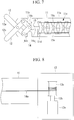
- a bending portion (movable portion) 11c for changing the directions of the gripping pieces 12 may be provided at a distal end of the body portion 11, as shown in Fig. 7 .
- the bending portion 11c has a plurality of bending pieces 11d that are arranged in the longitudinal-axis direction of the body portion 11 and that are coupled with each other so as to be pivotable about axes that intersect the longitudinal axis.
- the distal ends of bending driving wires 11e, which extend to the driving portion 13, are coupled with the bending piece 11d positioned at the most distal end, and, as with the manipulation wire 14a, the bending portion 11c is bent by pushing and pulling base ends of the bending driving wires 11e by means of the driving portion 13.
- the bending piece 11d positioned at the most distal end is formed of an electric insulator so that the bending driving wires 11e are electrically insulated from the gripping pieces 12 and the linkage mechanism 14b.
- any one of components that connect the gripping pieces 12 and the electric motor 13a, including the gripping pieces 12, may possess electrical insulating properties.
- a rotation shaft 13b and a pulley 13c that constitute a motive-power converting mechanism of the motor 13a in the driving portion 13 may possess electrical insulating properties.
- the pulley 13c is coaxially coupled with the rotation shaft 13b of the electric motor 13a, and a base-end portion of the manipulation wire 14a is wound around the pulley 13c.
- the rotation shaft 13b and/or the pulley 13c possessing electrical insulating properties function(s) in a similar manner as does the above-described insulating member 15, whereby it is possible to prevent the high-frequency current supplied to the gripping pieces 12 from affecting electrical systems of the driving portion 13, the manipulation input device 4, and the control portion 6.
- electrical systems of peripheral devices that are used together with the forceps device 1, such as an endoscope or the like into which the forceps device 1 is inserted are also prevented from being affected by noise or the like.
- a flexing joint portion (movable portion) 11f that can be flexed about an axis that intersects the longitudinal axis may be provided at the distal end of the body portion 11 instead of the bending portion 11c provided with the bending pieces 11d.
- the electrode contact portion 14c be provided farther on the base-end side than the bending portion 11c or the flexing joint portion 11f is, as shown in Fig. 9 .
- the electrode contact portion 14c in Fig. 9 is a member formed of a conductor and is provided at an outer circumferential surface of the sheath 11a.
- the surfaces of the electrode contact portion 14c are covered with an electric insulator, excluding surfaces that are externally exposed, thus electrically insulating the electrode contact portion 14c from the sheath 11a and objects that are built into the sheath 11a.
- the electric contact portion 14c is electrically connected with the pair of gripping pieces 12 inside the sheath 11a via a covered electric wire 14d that is covered with an electric insulator.
- the electric contact portion 14c As described above, by providing the electric contact portion 14c at a position that does not move following movements of the bending portion 11c or that of the flexing joint portion 11f, it is possible to move the bending portion 11c or the flexing joint portion 11f while maintaining the contact between the electrode 22 and the electric contact portion 14c.
- the electric contact portion 14c is disposed at a position further away from the tissue being gripped by the gripping pieces 12, it is possible to more easily perform manipulations for bringing the electrode 22 into contact with the electric contact portion 14c.
- a contact-detecting portion 16 that detects contact between the electric contact portion 14c and the electrode 22 may be provided.
- the contact-detecting portion 16 is formed of, for example, a microswitch provided at a side wall of the sheath 11a. Specifically, when the electrode 22 is press fitted between a pair of plate springs 16a that are disposed facing each other and that possess conductivity, while widening the gap between the plate springs 16a, a pressing button 16b provided behind the plate springs 16a is pressed. On the basis of the displacement of this pressing button 16b, contact between the plate springs 16a, which serve as the electric contact portion 14c, and the electrode 22 is detected. The contact-detecting portion 16 transmits detection signals to the control portion 6 when the contact between the electrode 22 and the electric contact portion 14c is detected.
- the control portion 6 controls the forceps device 1 and the high-frequency treatment device 2 on the basis of the detection signals received from the contact-detecting portion 16. For example, when contact between the electric contact portion 14c and the electrode 22 is detected, the control portion 6 permits only the portions that are farther on the distal-end side than the bending portion 11c or the flexing joint portion 11f of the forceps device 1 is to be driven, and switches the high-frequency current to be supplied to the electrode 22 from the high-frequency power source 25 to a current having intermittent waves that are suitable for performing the hemostatic treatment.
- the means of bringing the electrode 22 and the gripping pieces 12 into electrical contact is not limited thereto.
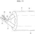
- distal-end portions (contact means) of the two treatment-tool channels 31 of the endoscope 3 may be inclined at relative angles at which extensions of the distal-end portions intersect each other. In this case, it is possible to bring the gripping pieces 12 and the electrode 22 into contact with each other just by adjusting the amounts by which the gripping pieces 12 and the electrode 22 protrude from the treatment-tool channels 31.
- the endoscope 3 may be provided with, at distal-end portions thereof, two arms (contact means) 32 that are provided in the vicinity of the distal end of the endoscope 3 and that protrude forward with respect to the endoscope 3.
- Each of the arms 32 has a bending portion 32a, and the orientation of the distal end of the arm 32 can be changed by means of bending motions of the bending portion 32a.
- An arm channel 32b that communicates with the treatment-tool channel 31 is provided in each of the arms 32.
- the gripping pieces 12 and the electrode 22 that protrude from distal ends of the individual arms 32 via the arm channels 32b can be brought into contact with each other by means of bending motions of the bending portions 32a.
- the surgical system 100 provided with the forceps device 1 and the high-frequency treatment device 2 that are of electrically-manipulated types has been described, as shown in Fig. 13 , the forceps device 1 and the high-frequency treatment device 2 may be of manually-manipulated types.
- the forceps device 1 is provided with, instead of the driving portion 13, a manipulation portion (motive-power output portion) 17 that is manually manipulated at a base end of the body portion 11, motive power generated by manual manipulations by the operator is transmitted to the manipulation wire 14a from the manipulation portion 17, and thus, the manipulation wire 14a is made to undergo linear motions in the longitudinal directions.
- a manually manipulated forceps device 1 because the gripping pieces 12 and the manipulation portion 17 are electrically insulated from each other by the insulating member 15, it is possible to use a conductor such as a metal or the like as the material for the manipulation portion 17.
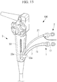
- a manipulation portion 33 of the endoscope 3 is provided with two insertion openings 33a that communicate with the treatment-tool channels 31, and into which the body portions 11 and 21 of the forceps device 1 and the high-frequency treatment device 2 are individually inserted.
- a cylindrical insulation cover (cover member) 7 having electrical insulating properties is connected to one of the insertion openings 33a into which the body portion 11 of the forceps device 1 is inserted.
- the insulation cover 7 be configured so as to be expandable in the longitudinal direction, for example, by forming at least a portion thereof in a bellows-like manner so that the length thereof changes in response to the movement of the body portion 11 in the longitudinal direction.
Landscapes
- Health & Medical Sciences (AREA)
- Life Sciences & Earth Sciences (AREA)
- Surgery (AREA)
- Engineering & Computer Science (AREA)
- Public Health (AREA)
- Veterinary Medicine (AREA)
- Biomedical Technology (AREA)
- Heart & Thoracic Surgery (AREA)
- Medical Informatics (AREA)
- Molecular Biology (AREA)
- Animal Behavior & Ethology (AREA)
- General Health & Medical Sciences (AREA)
- Nuclear Medicine, Radiotherapy & Molecular Imaging (AREA)
- Physics & Mathematics (AREA)
- Plasma & Fusion (AREA)
- Otolaryngology (AREA)
- Biophysics (AREA)
- Optics & Photonics (AREA)
- Pathology (AREA)
- Radiology & Medical Imaging (AREA)
- Ophthalmology & Optometry (AREA)
- Cardiology (AREA)
- Surgical Instruments (AREA)
- Endoscopes (AREA)
Abstract
Description
- The present invention relates to a forceps device and a surgical system.
- In the related art, there are known gripping forceps that are provided with: a pair of gripping pieces; a cylindrical sheath in which the pair of gripping pieces at the distal end thereof; a driving system provided at the base end of the sheath; and manipulation wires that connect the gripping pieces and the driving system and that open/close the pair of gripping pieces by manually or electrically pushing and pulling the manipulation wires by means of the driving system (for example, see Patent Literature 1).
- On the other hand, in a method that is generally used during surgery, as a simple hemostatic method, a bleeding point is pinched by using metal tweezers, and an electric scalpel is brought into contact with the tweezers to supply a high-frequency current to the tweezers from the electric scalpel, thus coagulating tissue around the bleeding point by means of heat.
- {PTL 1} Publication of Japanese Patent No.
5042700 - However, with the above-described hemostatic method employing a high-frequency current, there is a problem in that it is difficult to use normal gripping forceps, such as the ones in
Patent Literature 1, instead of the tweezers. Specifically, in normal gripping forceps, metal is used in components inside the sheath, such as the manipulation wires or the like. Therefore, the high-frequency current supplied to the gripping pieces can flow into the driving system via the manipulation wires or the like. In particular, in the case in which the gripping forceps are of an electrically-manipulated type, the driving system is provided with electric motors, and a control system for electrically controlling the motors is connected to the driving system. In other words, the operation of the gripping forceps and peripheral equipment may be affected by the high-frequency current also flowing into the electric motors and the control system. In addition, also with manually manipulated gripping forceps, electrical systems of peripheral devices that are used together with the gripping forceps, such as an image-acquisition element or the like of an endoscope into which the gripping forceps are inserted, may be affected by noise or the like. - The present invention has been conceived in light of the above-described circumstances, and an object thereof is to provide a forceps device that can also suitably be used as high-frequency hemostatic forceps by externally supplying a high-frequency current thereto, and to provide a surgical system provided with the same.
- In order to achieve the above-described object, the present invention provides the following solutions.
- A first aspect of the present invention is a forceps device including: an elongated body portion; a pair of gripping pieces that are provided at a distal end of the body portion, at least one of which possesses conductivity, and that can be opened/closed relative to each other; a motive-power output portion that is provided at a base end of the body portion and that outputs motive power; a motive-power converting mechanism that connects the pair of gripping pieces and the motive-power output portion, and that converts the motive power output by the motive-power output portion into relative opening/closing motions of the pair of gripping pieces; and an insulating member that is provided in a pathway connecting the pair of gripping pieces and the motive-power output portion via the motive-power converting mechanism, and that electrically insulates the pair of gripping pieces and the motive-power output portion from each other.
- With the first aspect of the present invention, by externally supplying a high-frequency current to at least one of the pair of gripping pieces, gripping a bleeding point, by using a high-frequency treatment device such as an electric scalpel, it is possible to achieve hemostasis by causing heat coagulation in tissue around the bleeding point between the pair of gripping pieces.
- In this case, the pair of gripping pieces are connected to the motive-power output portion via the motive-power converting mechanism for opening/closing them. Because the insulating member is provided on the pathway that connects the pair of gripping pieces and the motive-power output portion, the high-frequency current supplied to the gripping pieces does not reach the motive-power output portion. Therefore, even in the case in which an electric motor is employed as the motive-power output portion or in the case in which peripheral equipment is electrically connected via the motive-power output portion, the electric motor or the peripheral equipment is actuated without being affected by the high-frequency current. In addition, electrical systems of peripheral devices that are used together with the forceps device, such as an endoscope or the like into which the forceps device is inserted, are also prevented from being affected by noise or the like. By doing so, the present invention can suitably be used not only as gripping forceps but also as high-frequency hemostatic forceps. Note that the above-described "pathway " includes the pair of gripping pieces.
- In the above-described first aspect, the insulating member may be at least one of a plurality of components constituting the motive-power converting mechanism.
- By doing so, it is possible to electrically insulate the gripping pieces and the motive-power output portion without increasing the number of components.
- In the above-described first aspect, the motive-power converting mechanism is provided with: a manipulation wire that is placed along a longitudinal direction in the body portion and that is made to undergo linear motions in the longitudinal direction by means of the motive power output by the motive-power output portion; and a linkage mechanism that connects the manipulation wire and the pair of gripping pieces and that converts the linear motions of the manipulation wire into the relative opening/closing motions of the pair of gripping pieces, wherein the insulating member is provided between the manipulation wire and the linkage mechanism to couple the manipulation wire and the linkage mechanism.
- By doing so, it is possible to use a metal manipulation wire that has generally been used in the related art.
- In the above-described first aspect, the insulating member may be a second one of the gripping pieces formed of an electric insulator, and the motive-power converting mechanism is connected with the said second gripping piece, and causes the second gripping piece to undergo opening/closing motions with respect to a first one of the gripping pieces.
- By doing so, when performing the hemostatic treatment, by supplying a high-frequency current to the first gripping pieces in a state in which a hemostatic point is gripped with the pair of gripping pieces so that the second gripping piece is placed adjacent to the peripheral tissue, it is possible to protect the peripheral tissue other than the hemostatic point from the high-frequency current. In addition, because the second gripping piece that serves as an insulating member is interposed between the motive-power converting mechanism and the first gripping piece, the high-frequency current supplied to the first gripping piece does not reach the motive-power converting mechanism.
- In the above-described first aspect, the body portion may be provided with a cylindrical sheath that accommodates the motive-power converting mechanism and that possesses electrical insulating properties.
- By doing so, it is possible to electrically insulate between the interior and the exterior of the body portion.
- The above-described first aspect may include an electric contact portion that is provided at an intermediate position in a longitudinal direction of the sheath so as to be exposed at an exterior of the sheath, and that is electrically connected with the gripping pieces by passing through an interior of the sheath.
- By doing so, by bringing the high-frequency treatment device into contact with, instead of the gripping pieces, the electric contact portion that is positioned farther on the base-end side than the gripping pieces are, it is possible to easily supply the high-frequency current to the gripping pieces at a position away from the tissue being gripped by the pair of gripping pieces.
- In the above-described first aspect, the sheath may have, at an outer circumferential surface thereof, a slit that allows a portion, which is electrically connected with the pair of gripping pieces, of the motive-power converting mechanism to be exposed at the exterior, and the electric contact portion may be constituted of the portion of the motive-power converting mechanism.
- By doing so, because the electric contact portion is provided inside the sheath, it is possible to prevent the high-frequency treatment device from coming into contact with the tissue when supplying the high-frequency current. In addition, because the position of an electrode or the like of the high-frequency device inserted into the slit is stabilized, it is possible to stably maintain the electrical connection.
- In the above-described first aspect, the electric contact portion may be constituted of a member that is secured to an outer circumferential surface of the sheath and that possesses conductivity.
- By doing so, it is possible to provide the electric contact portion at an arbitrary position on the outer circumferential surface of the sheath.
- In the above-described first aspect, the body portion may be provided with, at a distal end thereof, a movable portion that can be bent or flexed about an axis that intersects the longitudinal axis of the body portion, and the electric contact portion may be provided farther on a base-end side than the movable portion is.
- By doing so, it is possible to move the gripping pieces by means of bending or flexing of the movable portion. In addition, because the electric contact portion is provided at a position that does not follow the movement of the movable portion, it is possible to maintain the contact between the electric contact portion and the high-frequency treatment device even while the movable portion is being moved.
- A second aspect of the present invention is a surgical system including: any one of forceps devices described above; a high-frequency treatment device that includes an elongated body portion, and an electrode provided at a distal end of the body portion, and that discharges a high-frequency current; an endoscope that has two treatment-tool channels into which the forceps device and the high-frequency treatment device are individually inserted; and a contact means for placing the pair of gripping pieces and the electrode, which protrude from a distal-end surface of the endoscope via the treatment-tool channels, at positions at which mutual electrical connections are established therebetween.
- With the second aspect of the present invention, the electrode is brought into contact with, by means of the contact means, the pair of gripping pieces gripping the bleeding point, and the high-frequency current is supplied to the gripping pieces from the electrode, and thus, it is possible to achieve hemostasis by causing heat coagulation in the tissue around the bleeding point between the pair of gripping pieces. In this case, it is also possible to suitably use the gripping forceps as high-frequency hemostatic forceps.
- In the above-described second aspect, the high-frequency treatment device may be provided with, between the electrode and the body portion, a joint portion that can be flexed, and the contact means may be constituted of the joint portion.
- By doing so, it is possible to move, by driving the joint portion, the electrode to a position at which contact is made with the gripping pieces.
- In the above-described second aspect, distal-end portions of the two treatment-tool channels may be inclined at angles that make extensions thereof intersect each other, and the contact means may be constituted of the distal-end portions of the two treatment-tool channels.
- By doing so, it is possible to place the gripping pieces and the electrode at positions at which they come into contact with each other just by making the gripping pieces and the electrode protrude from the distal-end surface of the endoscope via the treatment-tool channels.
- In the above-described second aspect, the endoscope may be provided with, in the vicinity of the distal end thereof, arms that individually have arm channels that communicate with the two treatment-tool channels and bending portions that can be bent, and the contact means may be constituted of the bending portions of the arms.
- By doing so, it is possible, by means of the bending motions of the bending portions, to place the gripping pieces and the electrode, which protrude via the treatment-tool channels and the arm channels, at positions at which the gripping pieces and the electrode come into contact with each other.
- The above-described second aspect may be provided with a manipulation input device that is manipulated by an operator; and a control portion that controls the forceps device and the high-frequency treatment device in accordance with manipulations input via the manipulation input device.
- By doing so, it is possible to electrically manipulate the forceps device and the high-frequency treatment device by using a manipulation input device that is provided separately from the forceps device and the high-frequency treatment device.
- The above-described second aspect may be provided with a contact-detecting portion that detects an electrical contact between the pair of gripping pieces and the electrode, wherein the control portion controls at least one of the forceps device and the high-frequency treatment device on the basis of detection results of the contact-detecting portion.
- By doing so, it is possible, by means of the contact-detecting portion, to automatically detect whether or not the hemostatic manipulations are performed on the basis of the presence/absence of electrical contact between the gripping pieces and the electrode, and it is possible to operate the forceps device and the high-frequency treatment device in accordance with different settings between during the hemostatic manipulations and during other manipulations.
- In the above-described second aspect, the endoscope may be provided with a cylindrical cover member that externally extends from an insertion opening of the treatment-tool channel into which the forceps device is inserted, and the cover member may possess electrical insulating properties and is expandable in a longitudinal direction thereof.
- By doing so, a portion of the forceps device that externally extends from the insertion opening of the treatment-tool channel can be electrically insulated from the surroundings by means of the cover member.
- The present invention affords an advantage in that the present invention can also suitably be used as high-frequency hemostatic forceps by externally supplying a high-frequency current thereto.
-
- {
Fig. 1} Fig. 1 is an overall configuration diagram of a surgical system according to an embodiment of the present invention. - {
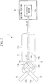
Fig. 2} Fig. 2 is an overall configuration diagram of a forceps device provided in the surgical system inFig. 1 . - {
Fig. 3} Fig. 3 is an overall configuration diagram of a high-frequency treatment device provided in the surgical system inFig. 1 . - {
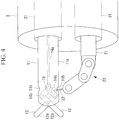
Fig. 4} Fig. 4 is a diagram for explaining motions of the forceps device and the high-frequency treatment device in the case in which the forceps device is used as high-frequency hemostatic forceps. - {
Fig. 5} Fig. 5 is a flowchart showing a surgical method employing the surgical system inFig. 1 . - {
Fig. 6A} Fig. 6A is a partial plan view showing a modification of the forceps device inFig. 2 . - {
Fig. 6B} Fig. 6B is a side view of the forceps device inFig. 6A . - {
Fig. 7} Fig. 7 is a partial configuration diagram showing another modification of the forceps device inFig. 2 . - {
Fig. 8} Fig. 8 is a partial configuration diagram showing another modification of the forceps device inFig. 2 . - {
Fig. 9} Fig. 9 is a partial configuration diagram showing another modification of the forceps device inFig. 2 . - {
Fig. 10} Fig. 10 is a partial configuration diagram showing another modification of the forceps device inFig. 2 . - {
Fig. 11} Fig. 11 is a diagram showing a modification of an endoscope inFig. 1 , and is a diagram for explaining motions of a forceps device and a high-frequency treatment device employed therein. - {
Fig. 12} Fig. 12 is a diagram showing another modification of the endoscope inFig. 1 , and is a diagram for explaining motions of a forceps device and a high-frequency treatment device employed therein. - {
Fig. 13} Fig. 13 is a partial configuration diagram of an endoscope that is used together with a manually manipulated forceps device and high-frequency treatment device. - A
forceps device 1 and a high-frequency treatment device 2, as well as asurgical system 100 provided with them, according to an embodiment of the present invention will be described below with reference to the drawings. - In the
surgical system 100 shown inFig. 1 , theforceps device 1 and the high-frequency treatment device 2 according to this embodiment pass through the interior of anendoscope 3, and thus, are inserted into the body of a patient P. - As shown in
Fig. 1 , thesurgical system 100 is provided with: theflexible endoscope 3 that is inserted into the body; amanipulation input device 4 that is manipulated by an operator O, such as a surgeon or the like; adisplay portion 5 that displays an image acquired by using theendoscope 3; and acontrol portion 6 that controls theforceps device 1 and the high-frequency treatment device 2 in accordance with manipulations input via themanipulation input device 4. - The
endoscope 3 has treatment-tool channels that are formed so as to pass through theendoscope 3 in a longitudinal direction and into whichbody portions 11 and 21 (described later) of theforceps device 1 and the high-frequency treatment device 2 can individually be inserted. - The
manipulation input device 4 includes: a manipulation table 41;manipulation arms 42 that are attached to the manipulation table 41; and foot switches 43. Themanipulation input device 4 transmits input signals in accordance with the manipulations input by using themanipulation arms 42 and the foot switches 43 to thecontrol portion 6. - The
control portion 6 is configured so as to electrically control theforceps device 1 and the high-frequency treatment device 2 in accordance with the input signals transmitted thereto from themanipulation input device 4. - As shown in
Fig. 2 , theforceps device 1 according to this embodiment is provided with: a forceps main unit having anelongated body portion 11 and a pair ofgripping pieces 12 that are provided at the distal end of thebody portion 11; a drivingportion 13 that is connected to the base end of thebody portion 11 and that has an electric motor (motive-power output portion) 13a that outputs a motive power in accordance with the control signals transmitted thereto from thecontrol portion 6; and a motive-power converting mechanism 14 and an insulatingmember 15 that are provided inside thebody portion 11. - The
body portion 11 has acylindrical sheath 11a that includes the motive-power converting mechanism 14 and the insulatingmember 15 as built-in components. Thesheath 11a possesses electrical insulating properties, thus serving as electrical insulation between the interior and the exterior of thebody portion 11. Thesheath 11a has, in a side wall thereof, aslit 11b that is formed so as to pass through the side wall in the wall-thickness direction. Theslit 11b is formed at a position corresponding to that of aportion 14c of alinkage mechanism 14b, described later, and thus, the portion of thelinkage mechanism 14b is exposed outside thesheath 11a via theslit 11b. The exposedportion 14c of thelinkage mechanism 14b forms an electric contact portion that serves as an electric contact point between thegripping pieces 12 and an electrode 22 (described later) of the high-frequency treatment device 2. In the following, thisportion 14c will also be referred to as an electric contact portion. - The pair of
gripping pieces 12 individually havegripping surfaces 12a, and thegripping surfaces 12a are disposed so as to face each other. - The motive-
power converting mechanism 14 is provided with: amanipulation wire 14a that extends along the longitudinal axis of thebody portion 11; and thelinkage mechanism 14b that is provided on the distal-end side of themanipulation wire 14a and that is coupled with base ends of thegripping pieces 12. Themanipulation wire 14a and thelinkage mechanism 14b are coupled with each other via the insulatingmember 15 provided therebetween. Themanipulation wire 14a is connected, at the base end thereof, to theelectric motor 13a inside the drivingportion 13 and is configured so as to be linearly moved in the longitudinal direction due to the motive power output by theelectric motor 13a. Thelinkage mechanism 14b is configured so as to convert the linear motion transmitted to the base end thereof from themanipulation wire 14a via the insulatingmember 15 into opening/closing motions of the pair ofgripping pieces 12. - The pair of
gripping pieces 12, themanipulation wire 14a, and thelinkage mechanism 14b are formed of a metal, such as stainless steel, titanium, tungsten, or the like, and possess conductivity. - Note that,
Fig. 2 shows thelinkage mechanism 14b that is connected to the base ends of both gripping pieces, and that is configured so as to perform the opening/closing motions of the pair ofgripping pieces 12 by simultaneously moving, in a pivoting manner, both grippingpieces 12 about axes that intersect the longitudinal axis of thebody portion 11; however, alternatively, it is permissible to employ a linkage mechanism that is connected only to the base end of one of thegripping pieces 12, and that is configured so as, by moving only this grippingpiece 12 in a pivoting manner, to perform opening/closing motions of thegripping piece 12 relative to the other grippingpiece 12. - The insulating
member 15 possesses electrical insulating properties and serves as electrical insulation between thelinkage mechanism 14b and themanipulation wire 14a. As the material for the insulatingmember 15, polyether ether ketone (PEEK), ceramic, polytetrafluoroethylene (PTFE), polycarbonate, or the like is used. A non-polar plastic, such as PTFE or the like, which has a lower dissipation factor, is more preferable because, as will be described later, it is possible to prevent deformation of the insulatingmember 15 due to an increase in temperature by suppressing dielectric superheating of the insulatingmember 15 when a high-frequency current is supplied to thegripping pieces 12. - As the insulating
member 15, it is permissible to use a member that is formed by covering an outer surface of a main unit made of a conductor with an insulator. As the insulator to be used in this case, a silicone resin, PTFE, white alumina (high-purity aluminum oxide) or the like is preferable. - As shown in
Fig. 3 , the high-frequency treatment device 2 according to this embodiment is provided with: anelongated body portion 21; the single rod-shapedelectrode 22 that is positioned on the distal-end side of thebody portion 21; an electric-scalpel main unit having a joint portion (contact means} 23 that couples thebody portion 21 and theelectrode 22; a drivingportion 24 that is connected to the base end of thebody portion 21 and that electrically drives thejoint portion 23; and a high-frequency power source 25 that supplies a high-frequency current to theelectrode 22 via the interiors of thebody portion 21 and thejoint portion 23. - The
joint portion 23 can be flexed about an axis that intersects the longitudinal axis of thebody portion 21. Here, as shown inFig. 4 , the flexing direction and the flexing angle of thejoint portion 23 are designed so that theelectrode 22 can be brought into contact with an outer surface of thegripping pieces 12 or theelectric contact portion 14c via theslit 11b in a state in which thegripping pieces 12 of theforceps device 1 and theelectrode 22 of the high-frequency treatment device 2 are disposed so as to protrude from treatment-tool channels 31 whose openings are at the distal-end surface of theendoscope 3. - Next, the operation of the thus-configured
surgical system 100 will be described. - The
body portions forceps device 1 and the high-frequency treatment device 2 are inserted into the large intestine of a patient P resting on a bed via the treatment-tool channels 31 of theendoscope 3 inserted into the large intestine from his/her anus. -
Fig. 5 is a flowchart showing procedures of a surgical method in which thesurgical system 100 is used. The operator O manipulates themanipulation input device 4 and actuates theforceps device 1 and the high-frequency treatment device 2 in the large intestine, thus executing the following procedures. - First, tissue in the vicinity of a site to be treated is gripped between the pair of
gripping pieces 12, and the gripped tissue is pulled, thus imparting a tensile force to the tissue in the site to be treated (step S1). Next, the high-frequency power source 25 starts to supply a high-frequency current to theelectrode 22, and an incision is made at the site to be treated by using the electrode 22 (step S2). - In the case in which the tissue starts to bleed while making the incision ("YES" in step S3), the supply of the high-frequency current is temporarily stopped (step S4), and the bleeding point is gripped by using the pair of gripping pieces 12 (step S5). Next, the
joint portion 23 of the high-frequency treatment device 2 is manipulated to bring theelectrode 22 into contact with theelectric contact portion 14c (step S6), thus restarting the supply of the high-frequency current (step S7). By doing so, the high-frequency current is supplied to the pair ofgripping pieces 12 that are electrically connected to theelectrode 22, and, because the tissue around the bleeding point being gripped by the pair ofgripping pieces 12 becomes coagulated by heat due to the high-frequency current, it is possible to achieve hemostasis thereof. - Continuous waves of the high-frequency current are suitable for making an incision, and intermittent waves of the high-frequency current are suitable for performing a hemostatic treatment. Therefore, the output setting of the high-
frequency power source 25 may be changed in steps S2 and S7, as appropriate. After hemostasis is achieved ("YES" in step S8), the supply of the high-frequency current is stopped (step S9), and the procedure to make the incision is continued (step S1). - In this case, with this embodiment, the insulating
member 15 that is provided in the pathway connecting the pair ofgripping pieces 12 and theelectric motor 13a electrically insulates theelectric motor 13a from the pair ofgripping pieces 12. Therefore, the high-frequency current supplied to the pair ofgripping pieces 12 does not flow into theelectric motor 13a nor themanipulation input device 4 and thecontrol portion 6 that are electrically connected to theelectric motor 13a, and thus, the high-frequency current does not affect the electrical systems of thesurgical system 100. In addition, electrical systems of peripheral devices that are used together with theforceps device 1, such as an endoscope or the like into which theforceps device 1 is inserted, are also prevented from being affected by noise or the like. Therefore, there is an advantage in that it is possible to suitably utilize theforceps device 1 as an energy treatment tool, in particular, as high-frequency hemostatic forceps. - In addition, the
slit 11b is provided at an intermediate position in the longitudinal direction of thesheath 11a and theelectric contact portion 14c that is electrically connected to thegripping pieces 12 is provided farther on the base-end side, and thus, there is an advantage in that manipulations for supplying the high-frequency current, by bringing theelectrode 22 into contact with the grippingpieces 12, can easily be performed at a position farther away from the tissue being gripped by the grippingpieces 12. In addition, by providing theelectric contact portion 14c inside thesheath 11b, theelectrode 22 that is in contact with theelectric contact portion 14c is accommodated in thesheath 11a in that state. Therefore, there is an advantage in that it is possible to more reliably prevent contact with the tissue around theelectrode 22. Furthermore, because the position of theelectrode 22 with respect to theelectric contact portion 14c is stabilized in a state in which theelectrode 22 is inserted into theslit 11b, there is an advantage in that it is possible to stably maintain the connection between theelectrode 22 and theelectric contact portion 14c. - Note that, in this embodiment, although the pair of
gripping pieces 12 both possess conductivity, alternatively, as shown inFigs. 6A and 6B , a firstgripping piece 121 may possess conductivity, and a secondgripping piece 122 may be formed of an electric insulator. In this case, the motive-power converting mechanism 14 is connected only to the secondgripping piece 122, and the motive-power converting mechanism 14 connected to the secondgripping piece 122 is coupled with the firstgripping piece 121. In other words, the secondgripping piece 122 also serves as an insulating member. Furthermore, the firstgripping piece 121 and the secondgripping piece 122 are coupled with each other via the insulatingmember 15. - Specifically, in
Figs. 6A and 6B , a combination of themanipulation wire 14a and apulley 14e is employed as the motive-power converting mechanism 14, instead of the combination of themanipulation wire 14a and thelinkage mechanism 14b. Thepulley 14e is formed as a portion of the secondgripping piece 122 at a base end of the secondgripping piece 122 of the pair ofgripping pieces pulley 14e has ahole 14f on the center axis thereof. The insulatingmember 15 is formed as a portion of the firstgripping piece 121 at a base end of the firstgripping piece 121, and the insulatingmember 15 is provided with aprotrusion 15a that extends in a direction that is orthogonal to the longitudinal axis of thebody portion 11. When theprotrusion 15a is inserted into thehole 14f of thepulley 14e, the secondgripping piece 122 is coupled with the firstgripping piece 121 so as to be rotatable about a pivoting axis A that is orthogonal to the longitudinal axis of thebody portion 11. Themanipulation wire 14a is connected to thepulley 14e so as to, by means of the linear motion thereof, alternatively impart rotational motions in clockwise and counterclockwise directions to thepulley 14e, and the rotations of thepulley 14e cause the secondgripping piece 122 to undergo opening/closing motions relative to thegripping piece 121, which is the first gripping piece in the pair. - By doing so, when gripping tissue, by placing the second
gripping piece 122 formed of an electric insulator on a side that is adjacent to the tissue, it is possible to protect the tissue around the bleeding point from the high-frequency current. - Note that, in the second
gripping piece 122, only an outer surface exposed to the tissue may be covered with an electric insulator, instead of forming the entirety thereof by using an electric insulator. By doing so also, it is possible to protect the peripheral tissue from the high-frequency current supplied to the firstgripping piece 121. In this case, it is necessary to provide an insulating member other than the secondgripping piece 122, like the insulatingmember 15 interposed between the firstgripping piece 121 and the secondgripping piece 122. - In the case in which the combination of the
manipulation wire 14a and thepulley 14e is employed as the motive-power converting mechanism 14, thepulley 14e may be provided for each of thegripping pieces power converting mechanism 14 may be configured so as to cause both grippingpieces pulleys 14e in directions opposite from each other. - In addition, in this embodiment, a bending portion (movable portion) 11c for changing the directions of the
gripping pieces 12 may be provided at a distal end of thebody portion 11, as shown inFig. 7 . - The bending
portion 11c has a plurality of bendingpieces 11d that are arranged in the longitudinal-axis direction of thebody portion 11 and that are coupled with each other so as to be pivotable about axes that intersect the longitudinal axis. The distal ends of bendingdriving wires 11e, which extend to the drivingportion 13, are coupled with thebending piece 11d positioned at the most distal end, and, as with themanipulation wire 14a, the bendingportion 11c is bent by pushing and pulling base ends of thebending driving wires 11e by means of the drivingportion 13. In the case in which the bendingportion 11c is provided in this way, thebending piece 11d positioned at the most distal end is formed of an electric insulator so that thebending driving wires 11e are electrically insulated from the grippingpieces 12 and thelinkage mechanism 14b. - In addition, in this embodiment, instead of providing the insulating
member 15 between themanipulation wire 14a and thelinkage mechanism 14b, any one of components that connect thegripping pieces 12 and theelectric motor 13a, including thegripping pieces 12, may possess electrical insulating properties. - For example, as shown in
Fig. 8 , at least one of arotation shaft 13b and apulley 13c that constitute a motive-power converting mechanism of themotor 13a in the drivingportion 13 may possess electrical insulating properties. Thepulley 13c is coaxially coupled with therotation shaft 13b of theelectric motor 13a, and a base-end portion of themanipulation wire 14a is wound around thepulley 13c. When therotation shaft 13b is rotated by actuating theelectric motor 13a, themanipulation wire 14a is pulled or pushed out due to rotation of thepulley 13c. - By doing so also, the
rotation shaft 13b and/or thepulley 13c possessing electrical insulating properties function(s) in a similar manner as does the above-described insulatingmember 15, whereby it is possible to prevent the high-frequency current supplied to thegripping pieces 12 from affecting electrical systems of the drivingportion 13, themanipulation input device 4, and thecontrol portion 6. In addition, electrical systems of peripheral devices that are used together with theforceps device 1, such as an endoscope or the like into which theforceps device 1 is inserted, are also prevented from being affected by noise or the like. - In addition, in this embodiment, as shown in
Fig. 9 , a flexing joint portion (movable portion) 11f that can be flexed about an axis that intersects the longitudinal axis may be provided at the distal end of thebody portion 11 instead of the bendingportion 11c provided with the bendingpieces 11d. - In the case in which the bending
portion 11c or the flexingjoint portion 11f is provided, it is preferable that theelectrode contact portion 14c be provided farther on the base-end side than the bendingportion 11c or the flexingjoint portion 11f is, as shown inFig. 9 . - The
electrode contact portion 14c inFig. 9 is a member formed of a conductor and is provided at an outer circumferential surface of thesheath 11a. The surfaces of theelectrode contact portion 14c are covered with an electric insulator, excluding surfaces that are externally exposed, thus electrically insulating theelectrode contact portion 14c from thesheath 11a and objects that are built into thesheath 11a. Theelectric contact portion 14c is electrically connected with the pair ofgripping pieces 12 inside thesheath 11a via a coveredelectric wire 14d that is covered with an electric insulator. - As described above, by providing the
electric contact portion 14c at a position that does not move following movements of the bendingportion 11c or that of the flexingjoint portion 11f, it is possible to move the bendingportion 11c or the flexingjoint portion 11f while maintaining the contact between theelectrode 22 and theelectric contact portion 14c. In addition, because theelectric contact portion 14c is disposed at a position further away from the tissue being gripped by the grippingpieces 12, it is possible to more easily perform manipulations for bringing theelectrode 22 into contact with theelectric contact portion 14c. - In addition, in this embodiment, a contact-detecting
portion 16 that detects contact between theelectric contact portion 14c and theelectrode 22 may be provided. - As shown in
Fig. 10 , the contact-detectingportion 16 is formed of, for example, a microswitch provided at a side wall of thesheath 11a. Specifically, when theelectrode 22 is press fitted between a pair of plate springs 16a that are disposed facing each other and that possess conductivity, while widening the gap between the plate springs 16a, apressing button 16b provided behind the plate springs 16a is pressed. On the basis of the displacement of thispressing button 16b, contact between the plate springs 16a, which serve as theelectric contact portion 14c, and theelectrode 22 is detected. The contact-detectingportion 16 transmits detection signals to thecontrol portion 6 when the contact between theelectrode 22 and theelectric contact portion 14c is detected. - The
control portion 6 controls theforceps device 1 and the high-frequency treatment device 2 on the basis of the detection signals received from the contact-detectingportion 16. For example, when contact between theelectric contact portion 14c and theelectrode 22 is detected, thecontrol portion 6 permits only the portions that are farther on the distal-end side than the bendingportion 11c or the flexingjoint portion 11f of theforceps device 1 is to be driven, and switches the high-frequency current to be supplied to theelectrode 22 from the high-frequency power source 25 to a current having intermittent waves that are suitable for performing the hemostatic treatment. - By doing so, it is possible to stably perform hemostatic manipulations. In addition, by employing a configuration in which the
electrode 22 is press fitted between the pair ofplate springs 16a, a sufficient contact area is ensured between the plate springs 16a, which serve as theelectric contact portion 14c, and theelectrode 22, and theelectrode 22 is stably secured to the plate springs 16a. By doing so, it is possible to stably supply the high-frequency current. - In addition, in this embodiment, although the
electrode 22 and thegripping pieces 12 are brought into electrical contact with each other by driving thejoint portion 23 of the high-frequency treatment device 2, the means of bringing theelectrode 22 and thegripping pieces 12 into electrical contact is not limited thereto. - For example, as shown in
Fig. 11 , distal-end portions (contact means) of the two treatment-tool channels 31 of theendoscope 3 may be inclined at relative angles at which extensions of the distal-end portions intersect each other. In this case, it is possible to bring thegripping pieces 12 and theelectrode 22 into contact with each other just by adjusting the amounts by which thegripping pieces 12 and theelectrode 22 protrude from the treatment-tool channels 31. - Alternatively, as shown in
Fig. 12 , theendoscope 3 may be provided with, at distal-end portions thereof, two arms (contact means) 32 that are provided in the vicinity of the distal end of theendoscope 3 and that protrude forward with respect to theendoscope 3. Each of thearms 32 has a bendingportion 32a, and the orientation of the distal end of thearm 32 can be changed by means of bending motions of the bendingportion 32a. Anarm channel 32b that communicates with the treatment-tool channel 31 is provided in each of thearms 32. The grippingpieces 12 and theelectrode 22 that protrude from distal ends of theindividual arms 32 via thearm channels 32b can be brought into contact with each other by means of bending motions of the bendingportions 32a. - In addition, in this embodiment, although the
surgical system 100 provided with theforceps device 1 and the high-frequency treatment device 2 that are of electrically-manipulated types has been described, as shown inFig. 13 , theforceps device 1 and the high-frequency treatment device 2 may be of manually-manipulated types. - In this case, the
forceps device 1 is provided with, instead of the drivingportion 13, a manipulation portion (motive-power output portion) 17 that is manually manipulated at a base end of thebody portion 11, motive power generated by manual manipulations by the operator is transmitted to themanipulation wire 14a from themanipulation portion 17, and thus, themanipulation wire 14a is made to undergo linear motions in the longitudinal directions. With such a manually manipulatedforceps device 1, because thegripping pieces 12 and themanipulation portion 17 are electrically insulated from each other by the insulatingmember 15, it is possible to use a conductor such as a metal or the like as the material for themanipulation portion 17. - As shown in
Fig. 13 , amanipulation portion 33 of theendoscope 3 is provided with twoinsertion openings 33a that communicate with the treatment-tool channels 31, and into which thebody portions forceps device 1 and the high-frequency treatment device 2 are individually inserted. A cylindrical insulation cover (cover member) 7 having electrical insulating properties is connected to one of theinsertion openings 33a into which thebody portion 11 of theforceps device 1 is inserted. - By doing so, a portion of the
body portion 11 of theforceps device 1 that is exposed at the exterior from theinsertion opening 33a can be accommodated in theinsulation cover 7. It is preferable that theinsulation cover 7 be configured so as to be expandable in the longitudinal direction, for example, by forming at least a portion thereof in a bellows-like manner so that the length thereof changes in response to the movement of thebody portion 11 in the longitudinal direction. -
- 1
- forceps device
- 2
- high-frequency treatment device
- 3
- endoscope
- 4
- manipulation input device
- 5
- display portion
- 6
- control portion
- 7
- insulation cover (cover member)
- 11
- body portion
- 11a
- sheath
- 11b
- slit
- 11c
- bending portion
- 11d
- bending piece
- 11e
- bending driving wire
- 11f
- flexing joint portion
- 12
- gripping piece
- 12a
- gripping surface
- 13
- driving portion
- 13a
- electric motor (motive-power output portion)
- 13b
- rotation shaft
- 13c
- pulley
- 14
- motive-power converting mechanism
- 14a
- manipulation wire
- 14b
- linkage mechanism
- 14c
- electric contact portion
- 14d
- covered electric wire
- 14e
- pulley
- 15
- insulating member
- 16
- contact-detecting portion
- 17
- manipulation portion (motive-power output portion)
- 21
- body portion
- 22
- electrode
- 23
- joint portion (contact means)
- 24
- driving portion
- 25
- high-frequency power source
- 31
- treatment-tool channel
- 32
- arm (contact means)
- 33
- manipulation portion
- 33a
- insertion opening
- 100
- surgical system
Claims (16)
- A forceps device comprising:an elongated body portion;a pair of gripping pieces that are provided at a distal end of the body portion, at least one of which possesses conductivity, and that can be opened/closed relative to each other;a motive-power output portion that is provided at a base end of the body portion and that outputs motive power;a motive-power converting mechanism that connects the pair of gripping pieces and the motive-power output portion, and that converts the motive power output by the motive-power output portion into relative opening/closing motions of the pair of gripping pieces; andan insulating member that is provided in a pathway connecting the pair of gripping pieces and the motive-power output portion via the motive-power converting mechanism, and that electrically insulates the pair of gripping pieces and the motive-power output portion from each other.
- A forceps device according to Claim 1, wherein the insulating member is at least one of a plurality of components constituting the motive-power converting mechanism.
- A forceps device according to Claim 1, wherein the motive-power converting mechanism is provided with:a manipulation wire that is placed along a longitudinal direction in the body portion and that is made to undergo linear motions in the longitudinal direction by means of the motive power output by the motive-power output portion; anda linkage mechanism that connects the manipulation wire and the pair of gripping pieces and that converts the linear motions of the manipulation wire into the relative opening/closing motions of the pair of gripping pieces,wherein the insulating member is provided between the manipulation wire and the linkage mechanism to couple the manipulation wire and the linkage mechanism.
- A forceps device according to any one of Claims 1 to 3,
wherein the insulating member is a second one of the gripping pieces formed of an electric insulator, and
the motive-power converting mechanism is connected with the second gripping piece, and causes the second gripping piece to undergo opening/closing motions with respect to a first one of the gripping pieces. - A forceps device according to any one of Claims 1 to 4, wherein the body portion is provided with a cylindrical sheath that accommodates the motive-power converting mechanism and that possesses electrical insulating properties.
- A forceps device according to Claim 5, further comprising:an electric contact portion that is provided at an intermediate position in a longitudinal direction of the sheath so as to be exposed at an exterior of the sheath, and that is electrically connected with the gripping pieces by passing through an interior of the sheath.
- A forceps device according to Claim 6,
wherein the sheath has, at an outer circumferential surface thereof, a slit that allows a portion, which is electrically connected with the pair of gripping pieces, of the motive-power converting mechanism to be exposed at the exterior, and
the electric contact portion is constituted of the portion of the motive-power converting mechanism. - A forceps device according to Claim 6, wherein the electric contact portion is constituted of a member that is secured to an outer circumferential surface of the sheath and that possesses conductivity.
- A forceps device according to any one of Claims 6 to 8,
wherein the body portion is provided with, at a distal end thereof, a movable portion that can be bent or flexed about an axis that intersects the longitudinal axis of the body portion, and
the electric contact portion is provided farther on a base-end side than the movable portion is. - A surgical system comprising:a forceps device according to any one of Claims 1 to 9;a high-frequency treatment device that includes an elongated body portion, and an electrode provided at a distal end of the body portion, and that discharges a high-frequency current;an endoscope that has two treatment-tool channels into which the forceps device and the high-frequency treatment device are individually inserted; anda contact means for placing the pair of gripping pieces and the electrode, which protrude from a distal-end surface of the endoscope via the treatment-tool channels, at positions at which mutual electrical connections are established therebetween.
- A surgical system according to Claim 10,
wherein the high-frequency treatment device is provided with, between the electrode and the body portion, a joint portion that can be flexed, and
the contact means is constituted of the joint portion. - A surgical system according to Claim 10,
wherein distal-end portions of the two treatment-tool channels are inclined at angles that make extensions thereof intersect each other, and
the contact means is constituted of the distal-end portions of the two treatment-tool channels. - A surgical system according to Claim 10,
wherein the endoscope is provided with, in the vicinity of the distal end thereof, arms that individually have arm channels that communicate with the two treatment-tool channels and bending portions that can be bent, and
the contact means is constituted of the bending portions of the arms. - A surgical system according to any one of Claims 10 to 13, further comprising:a manipulation input device that is manipulated by an operator; anda control portion that controls the forceps device and the high-frequency treatment device in accordance with manipulations input via the manipulation input device.
- A surgical system according to Claim 14, further comprising:a contact-detecting portion that detects an electrical contact between the pair of gripping pieces and the electrode,wherein the control portion controls at least one of the forceps device and the high-frequency treatment device on the basis of detection results of the contact-detecting portion.
- A surgical system according to any one of Claims 10 to 13,
wherein the endoscope is provided with a cylindrical cover member that externally extends from an insertion opening of the treatment-tool channel into which the forceps device is inserted, and
the cover member possesses electrical insulating properties and is expandable in a longitudinal direction thereof.
Applications Claiming Priority (2)
| Application Number | Priority Date | Filing Date | Title |
|---|---|---|---|
| JP2014126229A JP6325912B2 (en) | 2014-06-19 | 2014-06-19 | Forceps device and surgical system |
| PCT/JP2015/065946 WO2015194369A1 (en) | 2014-06-19 | 2015-06-02 | Forceps device and surgical system |
Publications (2)
| Publication Number | Publication Date |
|---|---|
| EP3158955A1 true EP3158955A1 (en) | 2017-04-26 |
| EP3158955A4 EP3158955A4 (en) | 2018-02-14 |
Family
ID=54935359
Family Applications (1)
| Application Number | Title | Priority Date | Filing Date |
|---|---|---|---|
| EP15809916.8A Withdrawn EP3158955A4 (en) | 2014-06-19 | 2015-06-02 | Forceps device and surgical system |
Country Status (5)
| Country | Link |
|---|---|
| US (1) | US10603061B2 (en) |
| EP (1) | EP3158955A4 (en) |
| JP (1) | JP6325912B2 (en) |
| CN (1) | CN106456201B (en) |
| WO (1) | WO2015194369A1 (en) |
Cited By (1)
| Publication number | Priority date | Publication date | Assignee | Title |
|---|---|---|---|---|
| CN115670564A (en) * | 2021-07-30 | 2023-02-03 | 麦德莱(苏州)医疗科技有限公司 | Jaw adjusting device and medical pressure applying forceps |
Families Citing this family (6)
| Publication number | Priority date | Publication date | Assignee | Title |
|---|---|---|---|---|
| CN107320188B (en) * | 2017-07-31 | 2021-03-30 | 成都博恩思医学机器人有限公司 | Surgical instrument for minimally invasive surgery robot and minimally invasive surgery robot |
| CN109381244B (en) * | 2018-11-16 | 2024-07-09 | 深圳市罗伯医疗科技有限公司 | Lifting arm and control method thereof |
| JP6815610B1 (en) * | 2019-08-08 | 2021-01-20 | リバーフィールド株式会社 | High frequency forceps |
| CN114391894A (en) * | 2021-12-10 | 2022-04-26 | 美科特医疗科技(苏州)有限公司 | Power mechanism of end effector |
| JP7662699B2 (en) * | 2023-04-14 | 2025-04-15 | 株式会社 コスミック エム イー | Surgical Support Equipment |
| CN118717279B (en) * | 2024-07-15 | 2025-06-10 | 浙江舒友仪器设备股份有限公司 | Bipolar electrode forceps suitable for natural cavity of human body and conductive reinforcing treatment device thereof |
Family Cites Families (12)
| Publication number | Priority date | Publication date | Assignee | Title |
|---|---|---|---|---|
| US5133735A (en) * | 1990-05-10 | 1992-07-28 | Symbiosis Corporation | Thumb-activated actuating member for imparting reciprocal motion to push rod of a disposable laparoscopic surgical instrument |
| US6241723B1 (en) * | 1997-10-15 | 2001-06-05 | Team Medical Llc | Electrosurgical system |
| US6953461B2 (en) | 2002-05-16 | 2005-10-11 | Tissuelink Medical, Inc. | Fluid-assisted medical devices, systems and methods |
| JP2004057588A (en) * | 2002-07-30 | 2004-02-26 | Olympus Corp | Surgical treatment instrument |
| US7232440B2 (en) | 2003-11-17 | 2007-06-19 | Sherwood Services Ag | Bipolar forceps having monopolar extension |
| EP1955657B1 (en) | 2007-02-08 | 2011-01-12 | Olympus Medical Systems Corp. | Treatment tool for endoscope |
| JP5042700B2 (en) | 2007-02-08 | 2012-10-03 | オリンパスメディカルシステムズ株式会社 | Endoscopic treatment tool |
| JP4914735B2 (en) | 2007-02-14 | 2012-04-11 | オリンパスメディカルシステムズ株式会社 | Endoscope system for controlling the position of the treatment tool |
| WO2009016834A1 (en) * | 2007-07-30 | 2009-02-05 | Isamu Koyama | Device for oral surgical operation of digestive tract |
| US8562513B2 (en) | 2008-05-20 | 2013-10-22 | Olympus Medical Systems Corp. | Endoscope device |
| EP2478860B1 (en) * | 2009-09-15 | 2019-01-16 | Olympus Corporation | High-frequency treatment tool |
| WO2014084409A1 (en) * | 2012-11-29 | 2014-06-05 | Olympus Corporation | Instrument, manipulator system, and control method of instrument |
-
2014
- 2014-06-19 JP JP2014126229A patent/JP6325912B2/en active Active
-
2015
- 2015-06-02 WO PCT/JP2015/065946 patent/WO2015194369A1/en not_active Ceased
- 2015-06-02 EP EP15809916.8A patent/EP3158955A4/en not_active Withdrawn
- 2015-06-02 CN CN201580032089.2A patent/CN106456201B/en active Active
-
2016
- 2016-12-13 US US15/377,136 patent/US10603061B2/en active Active
Cited By (1)
| Publication number | Priority date | Publication date | Assignee | Title |
|---|---|---|---|---|
| CN115670564A (en) * | 2021-07-30 | 2023-02-03 | 麦德莱(苏州)医疗科技有限公司 | Jaw adjusting device and medical pressure applying forceps |
Also Published As
| Publication number | Publication date |
|---|---|
| CN106456201B (en) | 2019-12-10 |
| JP2016002410A (en) | 2016-01-12 |
| JP6325912B2 (en) | 2018-05-16 |
| US10603061B2 (en) | 2020-03-31 |
| WO2015194369A1 (en) | 2015-12-23 |
| EP3158955A4 (en) | 2018-02-14 |
| CN106456201A (en) | 2017-02-22 |
| US20170086870A1 (en) | 2017-03-30 |
Similar Documents
| Publication | Publication Date | Title |
|---|---|---|
| US10603061B2 (en) | Forceps device and surgical system | |
| EP2762101B1 (en) | Electrosurgical instrument | |
| KR102110472B1 (en) | Bipolar cautery instrument | |
| EP3359060B1 (en) | Electrocautery hemostasis clip | |
| KR20110043662A (en) | Backend Mechanism for Four-Cable List | |
| KR20130008006A (en) | Direct pull surgical gripper | |
| CN114615918B (en) | Cables and wiring in the robotic arms of surgical equipment | |
| US10517665B2 (en) | Devices and methods for tissue sealing and mechanical clipping | |
| IL269091B1 (en) | Electrosurgery device | |
| US20170007346A1 (en) | Treatment device and surgical system | |
| JP2019103804A (en) | Probe applicator | |
| US20220104865A1 (en) | Surgical instrument | |
| CN106175923A (en) | Energy activated mechanism for surgical instruments | |
| US20200281643A1 (en) | Reduced capacitively leakage current in electrosurgical instruments | |
| WO2021117100A1 (en) | Endoscope system and method for changing rigidity of insertion part of endoscope | |
| CN115702818A (en) | Distal Rotation of Medical Devices | |
| US11259861B2 (en) | Common connector for monopolar and bipolar instruments | |
| US20220175410A1 (en) | Cutting device, forceps and gripping/cutting method | |
| CN212186675U (en) | Surgical instrument and surgical robot | |
| JP6628553B2 (en) | High frequency treatment tool for endoscope | |
| CN222955512U (en) | Ferrule | |
| EP3756603B1 (en) | Electrosurgical forceps | |
| GB2586916A (en) | Surgical apparatus |
Legal Events
| Date | Code | Title | Description |
|---|---|---|---|
| STAA | Information on the status of an ep patent application or granted ep patent |
Free format text: STATUS: THE INTERNATIONAL PUBLICATION HAS BEEN MADE |
|
| PUAI | Public reference made under article 153(3) epc to a published international application that has entered the european phase |
Free format text: ORIGINAL CODE: 0009012 |
|
| STAA | Information on the status of an ep patent application or granted ep patent |
Free format text: STATUS: REQUEST FOR EXAMINATION WAS MADE |
|
| 17P | Request for examination filed |
Effective date: 20170109 |
|
| AK | Designated contracting states |
Kind code of ref document: A1 Designated state(s): AL AT BE BG CH CY CZ DE DK EE ES FI FR GB GR HR HU IE IS IT LI LT LU LV MC MK MT NL NO PL PT RO RS SE SI SK SM TR |
|
| AX | Request for extension of the european patent |
Extension state: BA ME |
|
| DAV | Request for validation of the european patent (deleted) | ||
| DAX | Request for extension of the european patent (deleted) | ||
| A4 | Supplementary search report drawn up and despatched |
Effective date: 20180116 |
|
| RIC1 | Information provided on ipc code assigned before grant |
Ipc: A61B 18/12 20060101ALI20180110BHEP Ipc: A61B 17/28 20060101ALI20180110BHEP Ipc: A61B 1/018 20060101ALI20180110BHEP Ipc: A61B 1/00 20060101AFI20180110BHEP |
|
| RIC1 | Information provided on ipc code assigned before grant |
Ipc: A61B 18/12 20060101ALI20190626BHEP Ipc: A61B 1/018 20060101ALI20190626BHEP Ipc: A61B 17/28 20060101ALI20190626BHEP Ipc: A61B 1/00 20060101AFI20190626BHEP |
|
| GRAP | Despatch of communication of intention to grant a patent |
Free format text: ORIGINAL CODE: EPIDOSNIGR1 |
|
| STAA | Information on the status of an ep patent application or granted ep patent |
Free format text: STATUS: GRANT OF PATENT IS INTENDED |
|
| RIC1 | Information provided on ipc code assigned before grant |
Ipc: A61B 1/00 20060101ALI20190729BHEP Ipc: A61B 18/14 20060101ALI20190729BHEP Ipc: A61B 17/29 20060101AFI20190729BHEP Ipc: A61B 90/00 20160101ALN20190729BHEP Ipc: A61B 1/018 20060101ALI20190729BHEP Ipc: A61B 18/00 20060101ALN20190729BHEP Ipc: A61B 17/00 20060101ALN20190729BHEP |
|
| INTG | Intention to grant announced |
Effective date: 20190821 |
|
| RIN1 | Information on inventor provided before grant (corrected) |
Inventor name: YAMAMURA, NAHOKO Inventor name: KISHI, KOSUKE |
|
| STAA | Information on the status of an ep patent application or granted ep patent |
Free format text: STATUS: THE APPLICATION IS DEEMED TO BE WITHDRAWN |
|
| 18D | Application deemed to be withdrawn |
Effective date: 20200103 |