EP3158941A1 - Device for operating manipulator for surgical operation and system for manipulator for surgical operation - Google Patents
Device for operating manipulator for surgical operation and system for manipulator for surgical operation Download PDFInfo
- Publication number
- EP3158941A1 EP3158941A1 EP15809788.1A EP15809788A EP3158941A1 EP 3158941 A1 EP3158941 A1 EP 3158941A1 EP 15809788 A EP15809788 A EP 15809788A EP 3158941 A1 EP3158941 A1 EP 3158941A1
- Authority
- EP
- European Patent Office
- Prior art keywords
- surgical
- manipulator
- rotating member
- joint
- operating device
- Prior art date
- Legal status (The legal status is an assumption and is not a legal conclusion. Google has not performed a legal analysis and makes no representation as to the accuracy of the status listed.)
- Withdrawn
Links
- 230000033001 locomotion Effects 0.000 claims description 18
- 230000007246 mechanism Effects 0.000 claims description 12
- 230000035807 sensation Effects 0.000 claims description 10
- 239000012636 effector Substances 0.000 description 24
- 238000010586 diagram Methods 0.000 description 20
- 230000004048 modification Effects 0.000 description 12
- 238000012986 modification Methods 0.000 description 12
- 238000000034 method Methods 0.000 description 10
- 238000005452 bending Methods 0.000 description 9
- 210000003813 thumb Anatomy 0.000 description 9
- 238000001514 detection method Methods 0.000 description 6
- 210000003811 finger Anatomy 0.000 description 5
- 230000006870 function Effects 0.000 description 4
- 210000004247 hand Anatomy 0.000 description 3
- 230000005856 abnormality Effects 0.000 description 2
- 230000008901 benefit Effects 0.000 description 2
- 230000003247 decreasing effect Effects 0.000 description 2
- 238000006073 displacement reaction Methods 0.000 description 2
- 230000002708 enhancing effect Effects 0.000 description 2
- 230000000717 retained effect Effects 0.000 description 2
- 238000001356 surgical procedure Methods 0.000 description 2
- 230000008859 change Effects 0.000 description 1
- 230000000694 effects Effects 0.000 description 1
- ZZUFCTLCJUWOSV-UHFFFAOYSA-N furosemide Chemical compound C1=C(Cl)C(S(=O)(=O)N)=CC(C(O)=O)=C1NCC1=CC=CO1 ZZUFCTLCJUWOSV-UHFFFAOYSA-N 0.000 description 1
- 238000002357 laparoscopic surgery Methods 0.000 description 1
- 238000013507 mapping Methods 0.000 description 1
- 238000011022 operating instruction Methods 0.000 description 1
- 230000001954 sterilising effect Effects 0.000 description 1
- 238000004659 sterilization and disinfection Methods 0.000 description 1
Images














Classifications
-
- A—HUMAN NECESSITIES
- A61—MEDICAL OR VETERINARY SCIENCE; HYGIENE
- A61B—DIAGNOSIS; SURGERY; IDENTIFICATION
- A61B34/00—Computer-aided surgery; Manipulators or robots specially adapted for use in surgery
- A61B34/70—Manipulators specially adapted for use in surgery
- A61B34/74—Manipulators with manual electric input means
-
- A—HUMAN NECESSITIES
- A61—MEDICAL OR VETERINARY SCIENCE; HYGIENE
- A61B—DIAGNOSIS; SURGERY; IDENTIFICATION
- A61B1/00—Instruments for performing medical examinations of the interior of cavities or tubes of the body by visual or photographical inspection, e.g. endoscopes; Illuminating arrangements therefor
- A61B1/00131—Accessories for endoscopes
- A61B1/00133—Drive units for endoscopic tools inserted through or with the endoscope
-
- A—HUMAN NECESSITIES
- A61—MEDICAL OR VETERINARY SCIENCE; HYGIENE
- A61B—DIAGNOSIS; SURGERY; IDENTIFICATION
- A61B17/00—Surgical instruments, devices or methods
-
- A—HUMAN NECESSITIES
- A61—MEDICAL OR VETERINARY SCIENCE; HYGIENE
- A61B—DIAGNOSIS; SURGERY; IDENTIFICATION
- A61B46/00—Surgical drapes
- A61B46/10—Surgical drapes specially adapted for instruments, e.g. microscopes
-
- A—HUMAN NECESSITIES
- A61—MEDICAL OR VETERINARY SCIENCE; HYGIENE
- A61B—DIAGNOSIS; SURGERY; IDENTIFICATION
- A61B90/00—Instruments, implements or accessories specially adapted for surgery or diagnosis and not covered by any of the groups A61B1/00 - A61B50/00, e.g. for luxation treatment or for protecting wound edges
-
- B—PERFORMING OPERATIONS; TRANSPORTING
- B25—HAND TOOLS; PORTABLE POWER-DRIVEN TOOLS; MANIPULATORS
- B25J—MANIPULATORS; CHAMBERS PROVIDED WITH MANIPULATION DEVICES
- B25J13/00—Controls for manipulators
- B25J13/02—Hand grip control means
-
- B—PERFORMING OPERATIONS; TRANSPORTING
- B25—HAND TOOLS; PORTABLE POWER-DRIVEN TOOLS; MANIPULATORS
- B25J—MANIPULATORS; CHAMBERS PROVIDED WITH MANIPULATION DEVICES
- B25J3/00—Manipulators of leader-follower type, i.e. both controlling unit and controlled unit perform corresponding spatial movements
-
- A—HUMAN NECESSITIES
- A61—MEDICAL OR VETERINARY SCIENCE; HYGIENE
- A61B—DIAGNOSIS; SURGERY; IDENTIFICATION
- A61B1/00—Instruments for performing medical examinations of the interior of cavities or tubes of the body by visual or photographical inspection, e.g. endoscopes; Illuminating arrangements therefor
- A61B1/00112—Connection or coupling means
- A61B1/00121—Connectors, fasteners and adapters, e.g. on the endoscope handle
- A61B1/00128—Connectors, fasteners and adapters, e.g. on the endoscope handle mechanical, e.g. for tubes or pipes
-
- A—HUMAN NECESSITIES
- A61—MEDICAL OR VETERINARY SCIENCE; HYGIENE
- A61B—DIAGNOSIS; SURGERY; IDENTIFICATION
- A61B17/00—Surgical instruments, devices or methods
- A61B17/00234—Surgical instruments, devices or methods for minimally invasive surgery
Definitions
- the rotational joint provided at the distal end of the shaft is rotated just by rotational angle corresponding to that rotational angle. Because the flexing joint is disposed on the distal-end side of the rotational joint, when the rotational joint is rotated, the flexing joint is also rotated together. As a result, the flexing direction of the flexing joint is changed in association with the rotation of the rotational joint.
- the flexion input portion may be a switch that is attached to the rotating member and that is rotated together with rotation of the rotating member.
- the rotating member may be provided so as to be attachable to and detachable from the gripping portion, and the above-described aspect may be provided with a drape having a through-hole that supports the rotating member in a rotatable manner and that covers the entire gripping portion.
- the rotating member may be provided, at a surface thereof, with an indicator with which a specific circumferential-direction position of the rotating member can be identified via a tactile sensation.
- the gripping portion may be attached to the shaft so that the rotating member faces a proximal-end side of the shaft.
- the rotation input portion and the flexion input portion can be disposed in such a way that even the order of the rotational joint and the flexing joint displayed in an endoscope image are matched. By doing so, it is possible to provide an operational feeling that is as if the rotational joint and the flexing joint of the surgical manipulator are operated by directly gripping them.
- the surgical manipulator may be provided with a moving mechanism that drives a shaft in the longitudinal-axis direction
- the above-described aspect may be provided with a movement input portion with which movement instructions for the moving mechanism are input depending on the amount by which the gripping portion is moved in a front-to-rear direction.
- the manipulator 4 is provided with: two multi-joint treatment tools 8 that are disposed in a state in which the multi-joint treatment tools 8 protrude forward from a distal-end surface 3a of the inserted portion 3 into a viewing-field area of the flexible endoscope 2; a moving mechanism 10 for moving the individual multi-joint treatment tools 8 as a whole; and a multi-joint-treatment-tool driving mechanism 11 for electrically moving the individual multi-joint treatment tools 8.
- the moving mechanism 10 is provided with bending arms (not shown) that cause the individual multi-joint treatment tools 8 to pivot in predetermined directions.
- the moving mechanism 10 supports the multi-joint treatment tools 8 so as to be movable in directions in which the multi-joint treatment tools 8 are advanced and retracted with respect to the bending arms.
- the flexible portions 14 are connected to motor units 15 on the proximal-end sides thereof.
- Each one of the motor units 15 is provided with a plurality of motors (not shown) that separately impart tensile forces to the individual wires that pass through the interiors of the flexible portions 14 and is configured so as to be driven in accordance with instructions from the control portion 6.
- the motor units 15 are suspended at side surfaces of an operation table 16 so as to be pivotable about a horizontal axis with portions connecting with the flexible portions 14 facing vertically upward, and so as to allow position adjustment so that individual doctors (operators) can place the motor units 15 at optimal positions.
- the guide tube 13 is provided with channels (not shown) that pass therethrough over the entire length thereof in the longitudinal direction, and the flexible portions 14 are inserted into the channels so as to be movable in the longitudinal directions thereof. Advancing/retracting motions of the multi-joint treatment tools 8 with respect to the bending arms are executed by manually moving the flexible portions 14 themselves in the longitudinal directions on the proximal-end side of the guide tube 13.
- each of the manual operation portions 17 is provided with: two base portions 17a that are secured to the operation table 16 in a manner in which the positions thereof can be adjusted or in an attachable/detachable manner so that the individual doctors can place the base portions 17a at optimal positions; a cylindrical pivoting portion 17b that is supported so as to be pivotable about an axis that extends in the top-to-bottom direction with respect to the base portions 17a; and a cylindrical movable portion 17c that is disposed inside the pivoting portion 17b and that is supported so as to be movable in the longitudinal direction thereof.
- the operator while viewing an endoscope image of the area surrounding the affected site displayed on the monitor 7, the operator brings the distal ends of the multi-joint treatment tools 8 closer to the affected site.
- the operator grips the gripping portions 18a of the two electric operation portions 18 with both hands, and moves the electric operation portions 18 without operating the operation input portions 18b and 18c.
- the operator operates the second operation input portions 18c provided in the electric operation portions 18, thus performing precise positioning with respect to the affected site by electrically driving the rotational joints 8a and the flexing joints 8b of the individual multi-joint treatment tools 8, and actuates the end effectors 12 by operating the first operation input portions 18b. Accordingly, the affected site can be treated.
- the operator can check the rotational angle of the dial 18e on the basis of the position of the protrusion 18h on the dial 18e.
- the switches 18f and 18g are provided on either side of the protrusion 18h, the operator can easily check the positions of the switches 18f and 18g with reference to the protrusion 18h.
- a switch 19 itself which is provided in the dial 18e, may be utilized as a protrusion.
- two or more flexing joints 8b and 8c may be arranged in series on the distal-end side of the rotational joint 8a.
- two flexing joints 8b and 8c which flex in directions that are orthogonal to each other, are provided.
- two sets of switches 18f and 18g and 20a and 20b for separately operating the flexing joints 8b and 8c, which work in two directions that are orthogonal to each other, may be arranged on the dial 18e of the electric operation portion 18, as shown in Fig. 11 .
- a switch 21 itself which is disposed on the dial 18e, is constituted of a cross key, and flexion instructions for two orthogonal directions are input by using the switch 21 constituted of the cross key.
- the switch 21 constituted of the cross key serves as an indicator with which the direction of the dial 18e can be checked via the tactile sensation.
- switches 18f and 18g that rotate together with the dial 18e are provided on the dial 18e, alternatively, the same function may be achieved without providing the switches on the dial 18e. In the example illustrated in Fig. 14 , only the protrusion 18h is provided on the dial 18e.
- the signal generating portion generates and outputs, as shown in Figs. 15A and B , flexion instructions for pivoting the end effector 12 to the upper side (U) when the upper side of the dial 18e is pressed, flexion instructions for pivoting the end effector 12 to the down side (D) when the bottom side of the dial 18e is pressed, flexion instructions for pivoting the end effector 12 to the left side (L) when the left side of the dial 18e is pressed, and flexion instructions for pivoting the end effector 12 to right side (R) when the right side of the dial 18e is pressed.
- the operation key 30 may be used for aligning attitudes when the attitude of the multi-joint treatment tool 8 and the directions of the switches 18f and 18g of the electric operation portion 18 are displaced.
- the operation key 30 can also be utilized, by the same method, for performing the initializing motions when starting operation. In this way, by providing the operation key 30 at a position that is checked via the tactile sensation, it is possible to easily switch to the attitude aligning mode during operation for inputting rotation and inputting flexion via the dial 18e and the switches 18f and 18g without looking away from the monitor 7.
- the electric operation portion 18 is secured to the movable portion 17c so that the dial 18e faces the proximal-end side of the flexible portion 14, as shown in Fig. 4
- the electric operation portion 18 may be secured to the movable portion 17c so that the dial 18e faces the distal-end side of the flexible portion 14, as shown in Fig. 28 .
- a joystick-type switch 38 for operating the two flexing joints 8b and 8c is provided.
Landscapes
- Health & Medical Sciences (AREA)
- Life Sciences & Earth Sciences (AREA)
- Engineering & Computer Science (AREA)
- Surgery (AREA)
- Public Health (AREA)
- General Health & Medical Sciences (AREA)
- Veterinary Medicine (AREA)
- Animal Behavior & Ethology (AREA)
- Molecular Biology (AREA)
- Medical Informatics (AREA)
- Heart & Thoracic Surgery (AREA)
- Biomedical Technology (AREA)
- Nuclear Medicine, Radiotherapy & Molecular Imaging (AREA)
- Robotics (AREA)
- Mechanical Engineering (AREA)
- Pathology (AREA)
- Radiology & Medical Imaging (AREA)
- Optics & Photonics (AREA)
- Physics & Mathematics (AREA)
- Biophysics (AREA)
- Oral & Maxillofacial Surgery (AREA)
- Manipulator (AREA)
- Surgical Instruments (AREA)
- Endoscopes (AREA)
Abstract
Description
- The present invention relates to a surgical-manipulator operating device and a surgical-manipulator system.
- In the related art, there is a known surgical-manipulator system that employs a master-slave system and with which an electrical surgical manipulator that has two joints at a distal end of an elongate shaft introduced into a body via an endoscope channel is operated by using an operating device that is constituted of a joystick (for example, see Patent Literature 1).
- {PTL 1} Japanese Unexamined Patent Application, Publication No.
2009-101077 - However, in the case in which the two joints at the distal end of the shaft are provided in the form of a joint that is rotated about a longitudinal axis of an inserted portion and a flexing joint that is disposed on a distal-end side thereof and that is flexed about an axis that intersects the longitudinal axis, because the flexing joint on the distal-end side is rotated together with the rotational joint when the rotational joint is actuated to cause rotation, the flexing direction of the flexing joint is changed, and, because the operation direction specified by using the operating device constituted of the joystick is displaced with respect to the direction in which the distal end of the surgical manipulator is moved in an endoscope image, there is a problem in that an operator becomes confused.
- The present invention has been conceived in light of the above-described circumstances, and an object thereof is to provide a surgical-manipulator operating device and a surgical-manipulator system with which an operator can intuitively operate a surgical manipulator having at least two joints at a distal end thereof without becoming confused.
- In order to achieve the above-described object, the present invention provides the following solutions.
- An aspect of the present invention provides a surgical-manipulator operating device that is a device for operating a surgical manipulator provided with, at a distal end of an elongate shaft, a rotational joint that is rotatable about a longitudinal axis of the shaft, and a flexing joint that is on a distal-end side of the rotational joint and that can be flexed about an axis that intersects the longitudinal axis, the surgical-manipulator operating device including: a gripping portion that is gripped by an operator; a rotation input portion that is provided with a rotating member attached to the gripping portion in a rotatable manner and with which rotation instructions for the rotational joint are input in accordance with rotational angles of the rotating member; and a flexion input portion with which flexion instructions for the flexing joint are input in directions corresponding to fixed circumferential-direction operating positions on the rotating member.
- With this aspect, when the operator grips the gripping portion and rotates the rotating member with respect to the gripping portion, the rotational joint provided at the distal end of the shaft is rotated just by rotational angle corresponding to that rotational angle. Because the flexing joint is disposed on the distal-end side of the rotational joint, when the rotational joint is rotated, the flexing joint is also rotated together. As a result, the flexing direction of the flexing joint is changed in association with the rotation of the rotational joint. On the other hand, because the operating positions for inputting the flexion instructions for the flexing joint are fixed in the rotating member, when the rotating member is rotated in order to rotate the rotational joint, the operating positions for inputting the flexion instructions for the flexing joint are also rotated in association with the rotation of the rotating member.
- For example, in a state in which the longitudinal axis of the shaft is horizontally arranged, in the case in which the flexing direction of the flexing joint is in the top-to-bottom direction and the operating positions fixed in the rotating member for the flexing joint are disposed at top and bottom thereof, rotating the rotating member clockwise by 45° causes the rotational joint to be rotated clockwise by 45°, and, consequently, the flexing direction of the flexing joint is changed to a 45°-direction on the diagonally right hand side; however, because the operating positions on the rotating member are also rotated to the 45°-direction on the diagonally right hand side, the operator can intuitively understand the correspondence between the operating positions and the flexing directions, and thus, it is possible to input appropriate flexion instructions for flexing the flexing joint without causing confusion.
- In the above-described aspect, the flexion input portion may be a switch that is attached to the rotating member and that is rotated together with rotation of the rotating member.
- When the rotational joint of the manipulator is rotationally operated by rotating the rotating member of the operating device, the flexing direction of the flexing joint, which is disposed farther on the distal-end side than the rotational joint of the manipulator is, is also rotated. However, because the switch for inputting the flexion instructions, which is attached to the rotating member of the operating device, is also rotated together with the rotating member, by aligning the flexing direction of the flexing joint of the manipulator and the direction of the switch of the operating device for inputting the flexion instructions at the beginning of operation, the flexing direction and the direction of the switch are aligned even if the rotational joint is subsequently operated. Because of this, just by operating the switch, the operator can perform flexing operation of the flexing joint in the directions corresponding to the circumferential-direction positions of the switch. In other words, the operator can intuitively understand the correspondence between the positions of the switch and the flexing directions, and thus, it is possible to input appropriate flexion instructions for flexing the flexing joint without causing confusion.
- In addition, in the above-described aspect, the surgical manipulator may be provided with two flexing joints, and the flexion input portions for inputting flexion instructions for different flexing joints may be disposed at different circumferential-direction positions on the rotating member.
- In addition, in the above-described aspect, the flexion input portion may include: a plurality of sensors that are secured to the gripping portion, that are arranged in a circumferential direction of the rotating member, and that detect circumferential-direction positions at which the flexion instructions via the rotating member are input; and a signal generating portion that generates flexion instruction signals in accordance with the rotational angles of the rotating member and the positions of the sensors at which the flexion instructions are detected.
- By doing so, when the operator performs operation at one of the circumferential-direction positions of the rotating member in order to input the flexion instructions for the flexing joint, that circumferential-direction position is detected by the sensors. Although the operating positions for flexing the flexing joint in specific directions are fixed in the rotating member, because the sensors are secured to the gripping portion, even if the sensor that has detected the circumferential-direction position is the same, the resulting flexion instructions would be for a different direction of the flexing joint in the case in which the rotational angle of the rotating member is different.
- Therefore, by generating the flexion instruction signals, by means of the signal-generating portion, on the basis of the rotational angles of the rotating member and the positions of the sensors that have detected the flexion instructions, it is possible to rotate the operating positions for inputting the flexion instructions in accordance with the rotational angles of the rotating member, and thus, it is possible, even if the rotational joint is rotated, to input appropriate flexion instructions for flexing the flexing joint without causing the operator to become confused. In addition, because the sensors are not provided in the rotating member, movable wiring is not necessary, and thus, it is possible to simplify the device configuration.
- In addition, in the above-described aspect, the rotating member may be provided so as to be attachable to and detachable from the gripping portion, and the above-described aspect may be provided with a drape having a through-hole that supports the rotating member in a rotatable manner and that covers the entire gripping portion.
- By doing so, by attaching the rotating member, which is supported by the through-hole of the drape in a rotatable manner, to the gripping portion in the state in which the entire gripping portion is covered with the drape, it is possible to transmit the rotation of the rotating member to the gripping portion without damaging the drape while preventing, by using the drape, the gripping portion from becoming polluted. By doing so, it is possible to reuse the gripping portion by constituting the drape and the rotating member in a disposable manner.
- In addition, in the above-described aspect, the rotating member may be provided, at a surface thereof, with an indicator with which a specific circumferential-direction position of the rotating member can be identified via a tactile sensation.
- By doing so, the operator can recognize the state of the rotating member by touching, with a finger, the indicator provided on the surface of the rotating member, and thus, it is possible to input appropriate motion instructions for the rotational joint and the flexing joint via just the tactile sensations without having to visually check the rotating member.
- In addition, in the above-described aspect, the gripping portion may be attached to the shaft so that the rotating member faces a proximal-end side of the shaft.
- By doing so, the rotation input portion and the flexion input portion can be disposed so as to be aligned with the angle of the rotational joint and the flexing direction of the flexing joint displayed in an endoscope image.
- In addition, in the above-described aspect, the gripping portion may be attached to the shaft so that the rotating member faces a distal-end side of the shaft.
- By doing so, the rotation input portion and the flexion input portion can be disposed in such a way that even the order of the rotational joint and the flexing joint displayed in an endoscope image are matched. By doing so, it is possible to provide an operational feeling that is as if the rotational joint and the flexing joint of the surgical manipulator are operated by directly gripping them.
- In addition, in the above-described aspect, the surgical manipulator may be provided with a moving mechanism that drives a shaft in the longitudinal-axis direction, and the above-described aspect may be provided with a movement input portion with which movement instructions for the moving mechanism are input depending on the amount by which the gripping portion is moved in a front-to-rear direction.
- By doing so, by inputting the movement instructions by moving the gripping portion in the front-to-rear direction by using the movement input portion, it is possible to drive the shaft in the longitudinal-axis direction just by distances corresponding to the movement instructions by using the movement input portion.
- In addition, another aspect of the present invention provides a surgical-manipulator system provided with any one of the above-described surgical-manipulator operating devices.
- The present invention affords an advantage in that an operator can intuitively operate a surgical manipulator having at least two joints at a distal end thereof without causing confusion.
-
- {
Fig. 1} Fig. 1 is an overall configuration diagram showing a surgical-manipulator system according to an embodiment of the present invention. - {
Fig. 2} Fig. 2 is a perspective view showing, in outline, the configuration of a surgical manipulator employed in the surgical-manipulator system inFig. 1 . - {
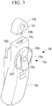
Fig. 3} Fig. 3 is a perspective view showing a surgical-manipulator operating device according to this embodiment. - {
Fig. 4} Fig. 4 is a perspective view for explaining a manipulator-operating portion provided in the surgical-manipulator system inFig. 1 . - {
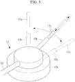
Fig. 5} Fig. 5 is a perspective view showing a manual operation portion provided in the manipulator-operating portion inFig. 4 . - {
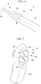
Fig. 6} Fig. 6 is a perspective view showing a state in which the pivoting direction of an end effector is rotated by a rotational joint of the surgical manipulator inFig. 2 . - {
Fig. 7} Fig. 7 is a perspective view for explaining the operation of the surgical-manipulator operating device inFig. 3 for performing the motion inFig. 6 . - {
Fig. 8} Fig. 8 is a perspective view showing a first modification of the surgical-manipulator operating device inFig. 3 . - {
Fig. 9} Fig. 9 is a perspective view showing a second modification of the surgical-manipulator operating device inFig. 3 . - {
Fig. 10A} Fig. 10A is a diagram showing, in outline, another axial configuration of the surgical manipulator. - {
Fig. 10B} Fig. 10B is a perspective view showing another axial configuration of the surgical manipulator. - {
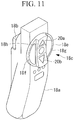
Fig. 11} Fig. 11 is a perspective view showing a third modification of the surgical-manipulator operating device inFig. 3 for operating the surgical manipulator inFig. 10 . - {
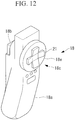
Fig. 12} Fig. 12 is a perspective view showing a fourth modification of the surgical-manipulator operating device inFig. 3 for operating the surgical manipulator inFig. 10 . - {
Fig. 13} Fig. 13 is a perspective view showing a fifth modification of the surgical-manipulator operating device inFig. 3 for operating the surgical manipulator inFig. 10 . - {
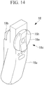
Fig. 14} Fig. 14 is a perspective view showing a sixth modification of the surgical-manipulator operating device inFig. 3 . - {
Fig. 15A} Fig. 15A is a schematic diagram for explaining the operation of the surgical-manipulator operating device inFig. 14 . - {
Fig. 15B} Fig. 15B is a schematic diagram for explaining the operation of the surgical-manipulator operating device inFig. 14 . - {
Fig. 15C} Fig. 15C is a schematic diagram for explaining the operation of the surgical-manipulator operating device inFig. 14 . - {
Fig. 15D} Fig. 15D is a schematic diagram for explaining the operation of the surgical-manipulator operating device inFig. 14 . - {
Fig. 16A} Fig. 16A is another schematic diagram for explaining the operation of the surgical-manipulator operating device inFig. 14 . - {
Fig. 16B} Fig. 16B is another schematic diagram for explaining the operation of the surgical-manipulator operating device inFig. 14 . - {
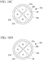
Fig. 16C} Fig. 16C is another schematic diagram for explaining the operation of the surgical-manipulator operating device inFig. 14 . - {
Fig. 16D} Fig. 16D is another schematic diagram for explaining the operation of the surgical-manipulator operating device inFig. 14 . - {
Fig. 17A} Fig. 17A is a perspective view showing a seventh modification of the surgical-manipulator operating device inFig. 3 and a portion thereof to be reused. - {
Fig. 17B} Fig. 17B is a perspective view showing the seventh modification of the surgical-manipulator operating device inFig. 3 and a drape thereof. - {
Fig. 18} Fig. 18 is a longitudinal cross-sectional diagram showing a dial attached to the drape inFig. 17 . - {
Fig. 19} Fig. 19 is a perspective view showing the surgical-manipulator operating device in a state in which the device is covered by the drape inFig. 17 . - {
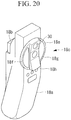
Fig. 20} Fig. 20 is a perspective view showing an eighth modification of the surgical-manipulator operating device inFig. 3 . - {
Fig. 21} Fig. 21 is a diagram showing an example of utilizing the dial for another usage. - {
Fig. 22} Fig. 22 is a diagram showing an example of a menu screen corresponding toFig. 21 . - {
Fig. 23A} Fig. 23A is a diagram for explaining a limit sensor that detects the two ends of a range of dial rotational angles. - {
Fig. 23B} Fig. 23B is a diagram for explaining the limit sensor that detects the two ends of the range of the dial rotational angles. - {
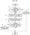
Fig. 24} Fig. 24 is a flowchart showing an angle correction method employing the limit sensor inFig. 23 . - {
Fig. 25} Fig. 25 is a diagram showing an example of a structure that prevents excessive turning of the dial. - {
Fig. 26} Fig. 26 is a diagram showing an example of a structure that precisely detects the rotational angles of the dial. - {
Fig. 27} Fig. 27 is a diagram showing an example of a structure for enhancing the ease of turning the dial. - {
Fig. 28} Fig. 28 is a perspective view showing a ninth modification of the surgical-manipulator operating device inFig. 3 . - {
Fig. 29} Fig. 29 is an overall configuration diagram showing a modification of the surgical-manipulator system inFig. 1 . - {
Fig. 30} Fig. 30 is an overall configuration diagram showing another modification of the surgical-manipulator system inFig. 1 . - A surgical-manipulator system 1 according to an embodiment of the present invention will be described below with reference to the drawings.
- As shown in
Fig. 1 , the surgical-manipulator system 1 according to this embodiment is provided with: a manipulator 4 that is actuated by being secured, by means of a belt-like securing tool 3b, to a distal-end portion of an insertedportion 3 of aflexible endoscope 2; a manipulator-operatingportion 5 for operating the manipulator 4; acontrol portion 6 that controls the manipulator 4 on the basis of operating instructions that are input via the manipulator-operatingportion 5; and amonitor 7 that displays images acquired by using theflexible endoscope 2. - The manipulator 4 is provided with: two
multi-joint treatment tools 8 that are disposed in a state in which themulti-joint treatment tools 8 protrude forward from a distal-end surface 3a of the insertedportion 3 into a viewing-field area of theflexible endoscope 2; a movingmechanism 10 for moving the individualmulti-joint treatment tools 8 as a whole; and a multi-joint-treatment-tool driving mechanism 11 for electrically moving the individualmulti-joint treatment tools 8. Themulti-joint treatment tools 8 each have a rotational joint 8a that is electrically operated and a flexing joint 8b that is disposed farther on the distal-end side than the rotational joint 8a is and is provided with, at the distal ends thereof,end effectors 12 such as gripping forceps, energy forceps, or the like. - The moving
mechanism 10 is provided with bending arms (not shown) that cause the individualmulti-joint treatment tools 8 to pivot in predetermined directions. In addition, the movingmechanism 10 supports themulti-joint treatment tools 8 so as to be movable in directions in which themulti-joint treatment tools 8 are advanced and retracted with respect to the bending arms. - By doing so, the moving
mechanism 10 can change the direction of themulti-joint treatment tools 8 as a whole by pivoting the bending arms in the predetermined directions, and theend effectors 12 at the distal ends thereof can be moved forward or backward in the viewing-field area of theflexible endoscope 2 by moving themulti-joint treatment tools 8 forward or backward as a whole by moving themulti-joint treatment tools 8 in the directions in which themulti-joint treatment tools 8 are advanced or retracted with respect to the bending arms. - An elongate and
soft guide tube 13 is connected at a proximal-end side of the bending arms of the movingmechanism 10. A plurality of wires (not shown) pass through theguide tube 13 over the entire length thereof. Distal ends of the wires are connected to the bending arms so as to pivot the bending arms by means of tensile forces therein. Proximal ends of the wires are connected to the manipulator-operating portion 5 (described later) disposed on a proximal-end side of theguide tube 13. - Elongate and soft flexible portions (shafts) 14 are individually connected to the
multi-joint treatment tools 8 on the proximal-end sides thereof. A plurality of wires (not shown) for driving thejoints multi-joint treatment tools 8 pass through the individualflexible portions 14 over the entire lengths thereof. Distal ends of the wires are connected to theindividual joints individual joints - Here, in describing this embodiment, the
multi-joint treatment tools 8 will be described by showing, in outline, example structures thereof inFig. 2 . Therotational joints 8a of themulti-joint treatment tools 8 are provided so as to be rotatable about the longitudinal axes of theflexible portions 14. In addition, the flexingjoints 8b of themulti-joint treatment tools 8 are attached on the distal-end sides of therotational joints 8a and are configured so as to pivot theend effectors 12 about axes that are orthogonal to the longitudinal axes of theflexible portions 14. - In addition, the
flexible portions 14 are connected tomotor units 15 on the proximal-end sides thereof. Each one of themotor units 15 is provided with a plurality of motors (not shown) that separately impart tensile forces to the individual wires that pass through the interiors of theflexible portions 14 and is configured so as to be driven in accordance with instructions from thecontrol portion 6. As shown inFig. 1 , themotor units 15 are suspended at side surfaces of an operation table 16 so as to be pivotable about a horizontal axis with portions connecting with theflexible portions 14 facing vertically upward, and so as to allow position adjustment so that individual doctors (operators) can place themotor units 15 at optimal positions. - The
guide tube 13 is provided with channels (not shown) that pass therethrough over the entire length thereof in the longitudinal direction, and theflexible portions 14 are inserted into the channels so as to be movable in the longitudinal directions thereof. Advancing/retracting motions of themulti-joint treatment tools 8 with respect to the bending arms are executed by manually moving theflexible portions 14 themselves in the longitudinal directions on the proximal-end side of theguide tube 13. - As shown in
Figs. 1 and4 , the manipulator-operatingportion 5 is provided with a pair of, that is, left and right,operating devices 5a in order for the operator to operate the manipulator-operatingportion 5 with both hands. For example, theleft operating device 5a is for operating the leftmulti-joint treatment tool 8, and theright operating device 5a is for operating the rightmulti-joint treatment tool 8. - Each of the
operating devices 5a is provided with amanual operation portion 17 and an electric operation portion (surgical-manipulator operating device) 18. - As shown in
Figs. 4 and5 , each of themanual operation portions 17 is provided with: twobase portions 17a that are secured to the operation table 16 in a manner in which the positions thereof can be adjusted or in an attachable/detachable manner so that the individual doctors can place thebase portions 17a at optimal positions; acylindrical pivoting portion 17b that is supported so as to be pivotable about an axis that extends in the top-to-bottom direction with respect to thebase portions 17a; and a cylindricalmovable portion 17c that is disposed inside the pivotingportion 17b and that is supported so as to be movable in the longitudinal direction thereof. - The
movable portions 17c are only allowed to be relatively moved in the longitudinal direction with respect to the pivotingportions 17b, and are restrained in terms of relative movement in the radial direction. By doing so, when forces are applied to themovable portions 17c in radial directions that are aligned with the pivoting directions of the pivotingportions 17b, themovable portions 17c are pivoted together with the pivotingportions 17b. - The
flexible portions 14 extend so as to pass through themovable portions 17c, the pivotingportions 17b, and thebase portions 17a, and are secured to themovable portions 17c in an attachable/detachable manner. - As shown in
Figs. 3 and4 , each of theelectric operation portions 18 according to this embodiment is provided with: a grippingportion 18a that is gripped by the operator; a firstoperation input portion 18b that is operated by the index finger of the hand (for example, right hand) gripping thegripping portion 18a; a secondoperation input portion 18c that is similarly operated by the thumb of the gripping hand; and an attachable/detachable portion 18d for securing theelectric operation portion 18 to themovable portion 17c of themanual operation portion 17 in an attachable/detachable manner. - The first
operation input portions 18b are configured so as to input, for example, instruction signals for actuating theend effectors 12 at the distal ends of themulti-joint treatment tools 8. In addition, each of the secondoperation input portions 18c is provided with: a dial (rotating member) 18e that rotates theend effector 12 about the longitudinal axis by driving the rotational joint 8a of themulti-joint treatment tool 8; and twoswitches dial 18e and that pivot the flexing joint 8b of themulti-joint treatment tool 8. - Each of the
dials 18e is formed in a discoid shape that is rotatable about an axis arranged substantially parallel to the longitudinal axis of themovable portion 17c, that is, the longitudinal axis of theflexible portion 14 that passes through themovable portion 17c, when theelectric operation portion 18 is secured to themovable portion 17c. In addition, in a state in which theelectric operation portion 18 is secured to themovable portion 17c, thedial 18e is disposed in a direction that faces the proximal-end side of theflexible portion 14. In other words, thedial 18e is disposed, facing the operator, at a position at which the thumb of the gripping hand would be placed when the operator grips thegripping portion 18a. - At the center of the
dial 18e, a protrusion (indicator) 18h that extends in the diameter direction is provided. Theprotrusion 18h is disposed between the twoswitches dial 18e with his/her thumb can easily recognize the position and the direction of theprotrusion 18h of thedial 18e via the tactile sensation of the thumb, and the operator can also easily recognize the positions of the twoswitches protrusion 18h via the tactile sensation of the thumb. - In addition, the two
switches protrusion 18h. By doing so, it is possible to correctly operate theswitches switches switches - In addition, each of the attachable/
detachable portions 18d is provided with: an attaching hole 18i at which themovable portion 17c is secured after passing therethrough; and a securingprotrusion 18k that secures thegripping portion 18a to themovable portion 17c in an attachable/detachable manner by being fitted to adepression 18j provided at a top end of thegripping portion 18a and by being twisted by 90° about the longitudinal axis. - Thus, as has been described above, by securing the
electric operation portions 18 to theflexible portions 14 via themovable portions 17c, it is possible to operate themanual operation portions 17 by means of theelectric operation portions 18 while theelectric operation portions 18 that the operator touches are prevented from coming into direct contact with theflexible portions 14 in which the distal-end portions thereof are inserted into the body of a patient. - The operation of the thus-configured
electric operation portions 18 and surgical-manipulator system 1 according to this embodiment will be described below. - In order to treat an affected site in the body of the patient by using the surgical-manipulator system 1 according to this embodiment, first, the inserted
portion 3 of theflexible endoscope 2 in which the twomulti-joint treatment tools 8 are secured in a state in which themulti-joint treatment tools 8 protrude from the distal-end surface 3a is manually introduced into the body, and the position of the distal end of theflexible endoscope 2 is adjusted so that the affected site is disposed in the viewing-field area of theflexible endoscope 2 while an image captured by using theflexible endoscope 2 is displayed on themonitor 7 and checked. - Next, while viewing an endoscope image of the area surrounding the affected site displayed on the
monitor 7, the operator brings the distal ends of themulti-joint treatment tools 8 closer to the affected site. In this case, first, the operator grips thegripping portions 18a of the twoelectric operation portions 18 with both hands, and moves theelectric operation portions 18 without operating theoperation input portions - In other words, by pivoting the pivoting
portions 17b with respect to thebase portions 17a of themanual operation portions 17 by moving theelectric operation portions 18 left and right, the bending arms of the movingmechanism 10 secured at the distal end of the insertedportion 3 are pivoted in corresponding directions, and thus, themulti-joint treatment tools 8 as a whole are moved left and right. In addition, themulti-joint treatment tools 8 as a whole are advanced and retracted by advancing and retracting themovable portions 17c with respect to the pivotingportions 17b of themanual operation portions 17 by moving theelectric operation portions 18 forward and backward. - By doing so, because the positions of the distal ends of the
multi-joint treatment tools 8 are roughly set with respect to the affected site, in this state, the operator operates the secondoperation input portions 18c provided in theelectric operation portions 18, thus performing precise positioning with respect to the affected site by electrically driving therotational joints 8a and the flexingjoints 8b of the individualmulti-joint treatment tools 8, and actuates theend effectors 12 by operating the firstoperation input portions 18b. Accordingly, the affected site can be treated. - In this case, with the
electric operation portion 18 according to this embodiment, for example, as shown inFig. 3 , when thedial 18e attached to thegripping portion 18a is disposed at a rotational position at which theprotrusion 18h is disposed in a top-to-bottom direction, the twoswitches dial 18e are disposed left and right of theprotrusion 18h. Therefore, by pressing one of theswitches Fig. 2 , it is possible to pivot theend effector 12 in the left-to-right direction by means of the flexing joint 8b. - When starting the operation, it is desirable to perform initialization in which the positional relationship of the
switches multi-joint treatment tool 8 appearing on the endoscope screen. In an initial state, initializing motions may be performed so that the directions of themulti-joint treatment tool 8 and theswitches electric operation portion 18 become the same. In addition, in a state in which, before starting the operation, the linkage (master-slave connection) between theelectric operation portion 18 and themulti-joint treatment tool 8 is disabled, the master and the slave may be connected by using a clutch switch (not shown) after the operator himself/herself has rotated thedial 18e to align the directions. The alignment of the directions may also be maintained by the same method in the case in which the direction of theswitches multi-joint treatment tool 8 are displaced during operation. - On the other hand, when the
dial 18e is rotated as shown inFig. 7 , the rotational joint 8a is rotated as shown inFig. 6 , and, consequently, the flexing direction of the flexing joint 8b disposed on the distal-end side of the rotational joint 8a is changed in a diagonally left-to-right direction. In this case, with this embodiment, because the twoswitches dial 18e, when thedial 18e is rotated as shown inFig. 7 , theswitches - In other words, from the perspective of the operator, the rotating direction of the rotational joint 8a of the
multi-joint treatment tool 8 in the endoscope image displayed on themonitor 7 is aligned with the rotating direction of thedial 18e of theelectric operation portion 18 he/she is gripping, and the pivoting direction of theend effector 12 due to the flexing joint 8b is also aligned with the direction in which theswitches dial 18e. Therefore, the operator can intuitively understand the directions in which thedial 18e and switches 18f and 18g should be operated in order to pivot theend effector 12 in a desired direction, and thus, there is an advantage in that, even if thedial 18e is rotated to actuate the rotational joint 8a, it is possible to input appropriate flexion instructions for flexing the flexing joint 18b without causing confusion. - In addition, with this embodiment, because the
protrusion 18h is provided on thedial 18e, the operator can check the rotational angle of thedial 18e on the basis of the position of theprotrusion 18h on thedial 18e. In addition, because theswitches protrusion 18h, the operator can easily check the positions of theswitches protrusion 18h. - In particular, because the rotational angle of the
dial 18e can be checked by using the indicator that can be checked via the tactile sensation, as with theprotrusion 18h, just by checking the direction of theprotrusion 18h via the tactile sensation of the thumb, it is also possible to check the arrangement direction of theswitches end effector 12 in the correct direction on the basis of the feeling of hands without looking away from themonitor 7. Accordingly, the operator can perform an operation in a state in which the operating field (theend effector 12 to be operated and a target tissue) is always in sight, and thus, it is possible to decrease the surgery time by enhancing the operation efficiency. - Because the operating field is always kept in sight, it is possible to prevent the
end effector 12 from being unintentionally brought close to the tissue. In addition, because theswitches switches switches protrusion 18h. - Note that, with this embodiment, although the
switches protrusion 18h, alternatively, theswitches protrusion 18h, as shown inFig. 8 . In this case, because the direction in which theprotrusion 18h extends is aligned with the direction in which theswitches dial 18e may be rotated so that the direction in which theprotrusion 18h extends becomes aligned with the pivoting direction of theend effector 12. - In addition, as shown in
Fig. 9 , aswitch 19 itself, which is provided in thedial 18e, may be utilized as a protrusion. - In addition, as the axial configuration of the
multi-joint treatment tool 8, as shown inFigs. 10A and B , two ormore flexing joints Figs. 10A and B , two flexingjoints - Also, in this case, two sets of
switches joints dial 18e of theelectric operation portion 18, as shown inFig. 11 . In the example illustrated inFig. 11 , it is possible to separately operate the flexing joints 8b and 8c, whose flexing directions are orthogonal to each other, by using one set of theswitches protrusion 18h and another set of theswitches protrusion 18h extends. - In addition, in the example illustrated in
Fig. 12 , aswitch 21 itself, which is disposed on thedial 18e, is constituted of a cross key, and flexion instructions for two orthogonal directions are input by using theswitch 21 constituted of the cross key. In addition, theswitch 21 constituted of the cross key serves as an indicator with which the direction of thedial 18e can be checked via the tactile sensation. - In addition, the example illustrated in
Fig. 13 is provided with a joystick-style switch 22b that can be pivoted in two directions along across-shaped groove 22a provided on thedial 18e. By doing so also, it is possible to input, even if thedial 18e is rotated to actuate the rotational joint 8a, appropriate flexion instructions for separately flexing the two flexingjoints - In addition, with this embodiment, although the
switches dial 18e are provided on thedial 18e, alternatively, the same function may be achieved without providing the switches on thedial 18e. In the example illustrated inFig. 14 , only theprotrusion 18h is provided on thedial 18e. - The
dial 18e is configured so that it is possible to selectively press given circumferential-direction positions in the vicinity of outer circumference thereof, andsensors 23a to 23d that detect the pressed circumferential-direction positions (operating positions) in thedial 18e are disposed on the back side of thedial 18e on thegripping portion 18a side. Also, a signal generating portion (not shown), which generates and outputs flexion instructions for the flexingjoints dial 18e and the operating positions detected by thesensors 23a to 23d, may be provided. - To be more specific, the four
sensors 23a to 23d are disposed at the top, bottom, left, and right around the center of thedial 18e, as shown inFig. 15 , so as to detect a pressed position among the circumferential directions of thedial 18e. A V-groove 24 at the outermost circumference inFig. 15 indicates, for example, the top-end position of theprotrusion 18h in thedial 18e inFig. 14 . - In the case in which the
protrusion 18h is placed in a range of ±45°, that is, a total of 90°, centered on the position inFig. 14 , the signal generating portion generates and outputs, as shown inFigs. 15A and B , flexion instructions for pivoting theend effector 12 to the upper side (U) when the upper side of thedial 18e is pressed, flexion instructions for pivoting theend effector 12 to the down side (D) when the bottom side of thedial 18e is pressed, flexion instructions for pivoting theend effector 12 to the left side (L) when the left side of thedial 18e is pressed, and flexion instructions for pivoting theend effector 12 to right side (R) when the right side of thedial 18e is pressed. - Then, in the case in which the
dial 18e is further rotated, and theprotrusion 18h is moved beyond the above-described 90°-range, as shown inFig. 15C , the flexion instructions generated by the signal generating portion are changed. In other words, when the position of the V-groove 24 at the outermost circumference is pressed, the flexion instructions for pivoting theend effector 12 to the upper side (U) are generated and output. In the case in which thedial 18e is further rotated, and theprotrusion 18h is moved beyond the next 90°-range also, as shown inFig. 15D , when the position of the V-groove 24 at the outermost circumference is pressed, the signal generating portion generates and outputs the flexion instructions for pivoting theend effector 12 to the upper side (U). - By doing so also, regardless of the rotational position of the
dial 18e, it is possible to always generate the flexion instructions for pivoting theend effector 12 to the upper side (U) when the position of the V-groove 24 is pressed. Therefore, because it is not necessary to dispose theswitches rotating dial 18e, it is possible to simplify the wiring for thesensors 23a to 23d. - In addition, in the example illustrated in
Fig. 15 , although the flexion instructions to be generated when the same sensors among thesensors 23a to 23d detect the operating positions are changed every time thedial 18e is rotated by a rotational angle of 90°, alternatively, in the case in which simultaneous detection by two of thesensors 23a to 23d is allowed, as shown inFig. 16 , the flexion instructions to be generated when the same sensors among thesensors 23a to 23d detect the operating positions may be changed every time thedial 18e is rotated by a rotational angle of 45°. - Specifically, in the case in which the
protrusion 18h is placed in a range of ±22.5°, that is, a total of 45°, centered on the position inFig. 14 , starting from the state in which the signal generating portion generates and outputs the flexion instructions for pivoting theend effector 12 to the upper side (U) when the upper side of thedial 18e is pressed, as shown inFig. 16A , the flexion instructions to be generated by the signal generating portion may be changed every time thedial 18e is rotated by 45° beyond the above-described 45°-range, as shown inFigs. 16B to D . - Without limitation to the above-described configuration, it is possible to realize the detection sensors by the same method regardless of the angular resolution. For example, in the case in which a detection sensor can continuously acquire all positional information of circumferential directions, as with a touch screen sensor, the detection sensor can be realized by moving the mapping relationship between the sensor and output by the amount by which the
dial 18e is rotated. - In addition, as shown in
Figs. 17 to 19 , by covering theelectric operation portion 18 with adrape 25, it is possible to reuse theelectric operation portion 18. Because theelectric operation portion 18 includes sensors such as theswitches electric operation portion 18 be covered with thedrape 25 that has been sterilized before operation, and that theelectric operation portion 18 be reused by disposing thedrape 25 after completing all operations. In this case, because it would be difficult to operate thedial 18e if thedrape 25 covers thedial 18e together with theelectric operation portion 18, as shown inFig. 17 , thedial 18e that can be attached to and detached from the grippingportion 18a may be provided on thedrape 25 side. - Specifically, as shown in
Fig. 18 , a through-hole 25a may be provided in a portion of thedrape 25, a ring-like seal member 26 may be placed in the through-hole 25a, and thedial 18e may be fitted to theseal member 26 in a rotatable manner. By doing so, starting from a separated state, as shown inFigs. 17A andB , the grippingportion 18a shown inFig. 17A is covered with thedrape 25 shown inFig. 17B , an attachingshaft 27a of thedial 18e on thedrape 25 side is fitted to afitting hole 27b of thegripping portion 18a, and thus, the entiregripping portion 18a can be covered with thedrape 25, with only thedial 18e exposed, as shown inFig. 19 . InFig. 19 , thereference sign 28 is a stopper ring (stretching rubber) that closes a hole through which acable 29 to be connected to thegripping portion 18a passes. Thestopper ring 28 may be stretched, the entiregripping portion 18a may be placed in thatstopper ring 28 to cover thegripping portion 18a with thedrape 25, and then, thedial 18e may be attached. - In addition, in this embodiment, an
operation key 30 for actuating theend effector 12 may be provided in thedial 18e, as shown inFig. 20 . In the example illustrated inFig. 20 , theoperation key 30 is provided in theprotrusion 18h. By doing so, the operator can check, with reference to theprotrusion 18h, the rotational angle of thedial 18e, as well as positions of theswitches operation key 30, via the tactile sensation without having to look at thedial 18e. - The operation key 30 may be used for aligning attitudes when the attitude of the
multi-joint treatment tool 8 and the directions of theswitches electric operation portion 18 are displaced. In addition, the operation key 30 can also be utilized, by the same method, for performing the initializing motions when starting operation. In this way, by providing the operation key 30 at a position that is checked via the tactile sensation, it is possible to easily switch to the attitude aligning mode during operation for inputting rotation and inputting flexion via thedial 18e and theswitches monitor 7. - In addition, in the case in which the
end effector 12 is a treatment tool that utilizes a high-frequency power source, the operation key 30 may be used as a switch for powering the high-frequency treatment tool. In this case also, it is possible to seamlessly perform the operation of thejoints multi-joint treatment tool 8 and the operation for powering the high-frequency treatment tool. - In addition, in this embodiment, the
dial 18e for the operator to operate themulti-joint treatment tool 8 may be utilized for another operation. - For example, another mode may be prepared in addition to a operation mode for operating the
multi-joint treatment tool 8, and in the case in which this other mode is selected, thedial 18e may be used as a selection dial for selecting functions A to D, as shown inFig. 21 . Also, the function selection may be confirmed when a switch on thedial 18e or a circumferential-direction portion of thedial 18e is pressed.Fig. 22 shows an example of a menu display when another mode is selected. - In addition, by providing a
limit sensor 31 that detects a predetermined rotational angle of thedial 18e, displacement between the rotational angle of thedial 18e and the rotational angle of the rotational joint 8a may be corrected by using the detection results from thelimit sensor 31. - For example, in the example illustrated in
Fig. 23 , ±180° at two ends of the rotational angle range of thedial 18e are detected by thelimit sensor 31. In the figure, thereference sign 32 is a dog for detection. - As a method of correcting the rotational angle displacement, for example, when the
limit sensor 31 detects +180°, as shown inFig. 24 , the angle is compared with the current angle of thedial 18e retained by the control portion 6 (step S1), and, in the case in which the angular difference is greater than a predetermined threshold, an alarm is issued to notify the presence of an abnormality in a rotation sensor (not shown) in theelectric operation portion 18 or the limit sensor 31 (step S2). On the other hand, in the case in which the angular difference is less than the threshold, the current angle of thedial 18e retained by thecontrol portion 6 is updated to +180° (step S3). - Next, the angle of the rotational joint 8a of the
multi-joint treatment tool 8 is acquired (step S4), the acquired angle of the rotational joint 8a is compared with +180° (step S5), the attitude aligning mode is executed in the case in which the angular difference is greater than the predetermined threshold (step S6), and the operation is continued in the case in which the angular difference is less than the threshold. - The following method is conceivable as a method of, in the attitude aligning mode, aligning the rotational angle of the
dial 18e with the angle of the rotational joint 8a of themulti-joint treatment tool 8. - Example methods include one in which, in the case in which the angle of the rotational joint 8a is +160° when the
limit sensor 31 has detected +180°, the rotational joint 8a is not moved until thedial 18e is rotated and the rotational angle of thedial 18e reaches +160°, and the rotational joint 8a is rotated in accordance with the rotation angle of thedial 18e when +160° is reached. - In addition, for example, within a predetermined motion range (for example, from +180° to +110°) of the
dial 18e, the rotational joint 8a may be moved by decreasing the ratio (motion-scale ratio) of the rotation angle of the rotational joint 8a with respect to the rotation angle of thedial 18e, and the rotational joint 8a may be moved by restoring the ratio to 1 when the angles are aligned (when +110° is reached). With this method, because the rotational joint 8a is always moved in accordance with the operation of thedial 18e, it is possible to allow the operator to perform the operation without causing him/her to become aware of an abnormality. - In addition, in the case in which initialization is performed without performing a special operation with regard to the correspondence relationship between the rotational joint 8a and the
dial 18e, the rotational joint 8a is moved by decreasing the motion-scale ratio of the rotational joint 8a with respect to thedial 18e until thelimit switch 31 detects the limit of the rotational-angle range of thedial 18e for the first time; and, in the case in which thelimit switch 31 has detected the limit, the angle of the rotational joint 8a at that time is acquired, and the rotational joint 8a is not moved regardless of the rotation of thedial 18e until the alignment with the acquired angle of the rotational joint 8a is achieved. - In addition, in order to prevent rapid rotation of the
dial 18e due to the operation by the operator, resistance may be imparted to the rotation of thedial 18e, for example, by pressing aplate spring 34 provided in thegripping portion 18a against agear 33 provided in thedial 18e, as shown inFig. 25 . - In addition, in order to precisely detect the rotational angle of the
dial 18e, as shown inFig. 26 , by providing arotation sensor 36 at asmall gear 35 that engages with thegear 33 provided in thedial 18e, the resolution may be enhanced by accelerating the rotation of therotation sensor 36 relative to that of thedial 18e. - In addition, in order to allow the operator to more easily rotate the
dial 18e, gripping with the fingers may be facilitated by providingirregularities 37 in the periphery of thedial 18e, as shown inFig. 27 . - In addition, in this embodiment, although the
electric operation portion 18 is secured to themovable portion 17c so that thedial 18e faces the proximal-end side of theflexible portion 14, as shown inFig. 4 , alternatively, theelectric operation portion 18 may be secured to themovable portion 17c so that thedial 18e faces the distal-end side of theflexible portion 14, as shown inFig. 28 . - In the example illustrated in
Fig. 28 , a joystick-type switch 38 for operating the two flexingjoints - By doing so, the
dial 18e is rotated by the thumb of the hand that is gripping thegripping portion 18a, and theswitch 38 is operated by the index finger and the middle finger thereof. In this case, while the arrangements of thejoints 8a to 8c in themulti-joint treatment tool 8 are such that the rotational joint 8a is arranged on the proximal-end side, and the two flexingjoints electric operation portion 18 are also such that thedial 18e for operating the rotational joint 8a is arranged on the proximal-end side and theswitch 38 for operating the flexingjoints multi-joint treatment tool 8 by gripping themulti-joint treatment tool 8. - In addition, in this embodiment, although the
multi-joint treatment tool 8 of the manipulator 4 secured to the insertedportion 3 by using thesecuring tool 3b is operated by using theelectric operation portion 18 secured to themovable portion 17c of themanual operation portion 17, alternatively, as shown inFig. 29 , theflexible portion 14 that is introduced via achannel 39 provided in the insertedportion 3 of theendoscope 2 may be pushed and pulled by the hand gripping theelectric operation portion 18 on the proximal-end side of the insertedportion 3. - In addition, without limitation to surgery in which the
endoscope 2 is employed, as described in this embodiment, the present invention can be applied to a treatment tool employed in laparoscopic surgery, as shown inFig. 30 . - In addition, in this embodiment, although the
movable portion 17c to which theflexible portion 14 is secured is manually moved in the longitudinal-axis direction, alternatively, a linear motion device (not shown) that electrically moves theflexible portion 14 in the longitudinal-axis direction may be provided, the electric operation portion may also be supported by the linear motion mechanism in a movable manner, and the linear motion device may be controlled by detecting the amount by which the electric operation portion is moved. -
- 1 surgical-manipulator system
- 8 multi-joint treatment tool (surgical manipulator)
- 8a rotational joint
- 8b, 8c flexing joint
- 14 flexible portion (shaft)
- 18 electric operation portion (surgical-manipulator operating device)
- 18a gripping portion
- 18c second operation input portion (rotation input portion)
- 18e dial (rotating member)
- 18f, 18g switch (flexion input portion)
- 18h protrusion (indicator)
- 23a to 23d sensor
- 25 drape
- 25a through-hole
Claims (10)
- A surgical-manipulator operating device that is a device for operating a surgical manipulator provided with, at a distal end of an elongate shaft, a rotational joint that is rotatable about a longitudinal axis of the shaft, and a flexing joint that is on a distal-end side of the rotational joint and that can be flexed about an axis that intersects the longitudinal axis, the surgical-manipulator operating device comprising:a gripping portion that is gripped by an operator;a rotation input portion that is provided with a rotating member attached to the gripping portion in a rotatable manner and with which rotation instructions for the rotational joint are input in accordance with rotational angles of the rotating member; anda flexion input portion with which flexion instructions for the flexing joint are input in directions corresponding to fixed circumferential-direction operating positions on the rotating member.
- A surgical-manipulator operating device according to Claim 1, wherein the flexion input portion is a switch that is attached to the rotating member and that is rotated together with rotation of the rotating member.
- A surgical-manipulator operating device according to Claim 2,
wherein the surgical manipulator is provided with two flexing joints, and
the flexion input portions for inputting flexion instructions for different flexing joints are disposed at different circumferential-direction positions on the rotating member. - A surgical-manipulator operating device according to Claim 1,
wherein the flexion input portion comprises:a plurality of sensors that are secured to the gripping portion, that are arranged in a circumferential direction of the rotating member, and that detect circumferential-direction positions at which the flexion instructions via the rotating member are input; anda signal generating portion that generates flexion instruction signals in accordance with the rotational angles of the rotating member and the positions of the sensors at which the flexion instructions are detected. - A surgical-manipulator operating device according to Claim 4,
wherein the rotating member is provided so as to be attachable to and detachable from the gripping portion,
the surgical-manipulator operating device further comprising:a drape that is provided with a through-hole that supports the rotating member in a rotatable manner and that covers the entire gripping portion. - A surgical-manipulator operating device according to any one of Claims 1 to 5, wherein the rotating member is provided, at a surface thereof, with an indicator with which a specific circumferential-direction position of the rotating member can be identified via a tactile sensation.
- A surgical-manipulator operating device according to any one of Claims 1 to 6, wherein the gripping portion is attached to the shaft so that the rotating member faces a proximal-end side of the shaft.
- A surgical-manipulator operating device according to any one of Claims 1 to 6, wherein the gripping portion is attached to the shaft so that the rotating member faces a distal-end side of the shaft.
- A surgical-manipulator operating device according to any one of Claims 1 to 8, wherein the surgical manipulator is provided with a moving mechanism that drives a shaft in the longitudinal-axis direction,
the surgical-manipulator operating device further comprising:a movement input portion with which movement instructions for the moving mechanism are input depending on the amount by which the gripping portion is moved in a front-to-rear direction. - A surgical-manipulator system comprising:a surgical-manipulator operating device according to any one of Claims 1 to 9.
Applications Claiming Priority (2)
| Application Number | Priority Date | Filing Date | Title |
|---|---|---|---|
| JP2014124462A JP6238844B2 (en) | 2014-06-17 | 2014-06-17 | Surgical manipulator operating device and surgical manipulator system |
| PCT/JP2015/062865 WO2015194262A1 (en) | 2014-06-17 | 2015-04-28 | Device for operating manipulator for surgical operation and system for manipulator for surgical operation |
Publications (2)
| Publication Number | Publication Date |
|---|---|
| EP3158941A1 true EP3158941A1 (en) | 2017-04-26 |
| EP3158941A4 EP3158941A4 (en) | 2018-01-31 |
Family
ID=54935257
Family Applications (1)
| Application Number | Title | Priority Date | Filing Date |
|---|---|---|---|
| EP15809788.1A Withdrawn EP3158941A4 (en) | 2014-06-17 | 2015-04-28 | Device for operating manipulator for surgical operation and system for manipulator for surgical operation |
Country Status (5)
| Country | Link |
|---|---|
| US (1) | US10660720B2 (en) |
| EP (1) | EP3158941A4 (en) |
| JP (1) | JP6238844B2 (en) |
| CN (1) | CN106456261B (en) |
| WO (1) | WO2015194262A1 (en) |
Families Citing this family (8)
| Publication number | Priority date | Publication date | Assignee | Title |
|---|---|---|---|---|
| USD865638S1 (en) | 2017-01-31 | 2019-11-05 | Israel Aerospace Industries Ltd. | Joystick |
| USD840360S1 (en) | 2017-05-30 | 2019-02-12 | Cmr Surgical Limited | Hand controller for controlling surgical robot |
| US11032481B2 (en) | 2018-07-06 | 2021-06-08 | Medos International Sarl | Camera scope electronic variable prism |
| US11202014B2 (en) | 2018-07-06 | 2021-12-14 | Medos International Sari | Camera scope electronic variable angle of view |
| US11625107B2 (en) * | 2019-06-27 | 2023-04-11 | Intuitive Surgical Operations, Inc. | System and method for motion mode management |
| DE102020115258B3 (en) * | 2020-06-09 | 2021-09-16 | Karl Storz Se & Co. Kg | Endoscope with swiveling image capturing device |
| JP7710923B2 (en) * | 2021-08-18 | 2025-07-22 | キヤノン株式会社 | electronic equipment |
| USD1018482S1 (en) * | 2022-05-17 | 2024-03-19 | Wuhan United Imaging Healthcare Surgical Technology Co., Ltd. | Controller for interventional surgery robot |
Family Cites Families (29)
| Publication number | Priority date | Publication date | Assignee | Title |
|---|---|---|---|---|
| JPH05192348A (en) | 1991-03-14 | 1993-08-03 | Olympus Optical Co Ltd | Endoscopic treating tool |
| JP3810177B2 (en) | 1997-03-25 | 2006-08-16 | オリンパス株式会社 | Endoscope system |
| JP2003010099A (en) | 2001-06-29 | 2003-01-14 | Olympus Optical Co Ltd | Endoscope |
| US6793653B2 (en) | 2001-12-08 | 2004-09-21 | Computer Motion, Inc. | Multifunctional handle for a medical robotic system |
| US6872178B2 (en) * | 2002-11-18 | 2005-03-29 | Andrew Mark Weinberg | Colonoscope apparatus and method |
| US20050187575A1 (en) * | 2004-02-12 | 2005-08-25 | Hallbeck M. S. | Ergonomic handle and articulating laparoscopic tool |
| JP4377827B2 (en) * | 2004-03-30 | 2009-12-02 | 株式会社東芝 | Manipulator device |
| EP1584300A3 (en) * | 2004-03-30 | 2006-07-05 | Kabushiki Kaisha Toshiba | Manipulator apparatus |
| JP4287354B2 (en) * | 2004-10-25 | 2009-07-01 | 株式会社日立製作所 | Surgical instruments |
| JP4528136B2 (en) * | 2005-01-11 | 2010-08-18 | 株式会社日立製作所 | Surgical device |
| ATE543455T1 (en) * | 2005-03-29 | 2012-02-15 | Toshiba Kk | MANIPULATOR |
| JP5121132B2 (en) | 2005-11-02 | 2013-01-16 | オリンパスメディカルシステムズ株式会社 | Endoscope system and operation assist device for endoscope |
| US7860536B2 (en) | 2006-01-05 | 2010-12-28 | Apple Inc. | Telephone interface for a portable communication device |
| KR101255512B1 (en) * | 2006-06-30 | 2013-04-16 | 엘지디스플레이 주식회사 | Method For Fabricating Thin Film Transistor Array Substrate |
| JP2008264253A (en) | 2007-04-20 | 2008-11-06 | Olympus Medical Systems Corp | Medical treatment tool and endoscope treatment system |
| JP5011060B2 (en) | 2007-10-22 | 2012-08-29 | オリンパスメディカルシステムズ株式会社 | Medical equipment |
| JP5237608B2 (en) | 2007-10-25 | 2013-07-17 | オリンパスメディカルシステムズ株式会社 | Medical equipment |
| US8641663B2 (en) | 2008-03-27 | 2014-02-04 | St. Jude Medical, Atrial Fibrillation Division, Inc. | Robotic catheter system input device |
| JP5308716B2 (en) * | 2008-05-21 | 2013-10-09 | オリンパスメディカルシステムズ株式会社 | Electronic endoscope device |
| JP5773884B2 (en) * | 2008-12-31 | 2015-09-02 | セント・ジュード・メディカル・エイトリアル・フィブリレーション・ディヴィジョン・インコーポレーテッド | Robot catheter system input device |
| CN102469917B (en) * | 2009-08-26 | 2014-12-24 | 奥林巴斯医疗株式会社 | Endoscope device |
| US8480703B2 (en) | 2010-11-19 | 2013-07-09 | Covidien Lp | Surgical device |
| JP2013188323A (en) * | 2012-03-13 | 2013-09-26 | Nagoya Univ | Forceps |
| JP2013206662A (en) | 2012-03-28 | 2013-10-07 | Canon Inc | Information setting device |
| JP6242101B2 (en) * | 2013-07-26 | 2017-12-06 | オリンパス株式会社 | Medical device and system |
| JP6234267B2 (en) * | 2014-02-21 | 2017-11-22 | オリンパス株式会社 | Surgical manipulator operating device and surgical manipulator system |
| JP6261376B2 (en) | 2014-02-25 | 2018-01-17 | オリンパス株式会社 | Surgical manipulator system |
| CN107106251B (en) * | 2015-02-05 | 2019-10-22 | 奥林巴斯株式会社 | manipulator |
| US10182812B1 (en) * | 2017-09-11 | 2019-01-22 | Aqeel J. A. GH. H. Ashraf | Needle holder |
-
2014
- 2014-06-17 JP JP2014124462A patent/JP6238844B2/en active Active
-
2015
- 2015-04-28 CN CN201580029585.2A patent/CN106456261B/en active Active
- 2015-04-28 WO PCT/JP2015/062865 patent/WO2015194262A1/en not_active Ceased
- 2015-04-28 EP EP15809788.1A patent/EP3158941A4/en not_active Withdrawn
-
2016
- 2016-12-09 US US15/374,139 patent/US10660720B2/en active Active
Also Published As
| Publication number | Publication date |
|---|---|
| US20170086933A1 (en) | 2017-03-30 |
| JP6238844B2 (en) | 2017-11-29 |
| CN106456261B (en) | 2019-06-28 |
| CN106456261A (en) | 2017-02-22 |
| EP3158941A4 (en) | 2018-01-31 |
| US10660720B2 (en) | 2020-05-26 |
| WO2015194262A1 (en) | 2015-12-23 |
| JP2016002274A (en) | 2016-01-12 |
Similar Documents
| Publication | Publication Date | Title |
|---|---|---|
| US10660720B2 (en) | Surgical-manipulator operating device and surgical-manipulator system | |
| CN103607971B (en) | Medical master-slave operator | |
| JP7080861B2 (en) | Surgical system | |
| US8231610B2 (en) | Robotic surgical system for laparoscopic surgery | |
| US9974620B2 (en) | Manipulator system, and medical system | |
| US10022871B2 (en) | Medical system and control method therefor | |
| JP6203249B2 (en) | Master-slave system | |
| JP6064095B2 (en) | Operation input device and medical manipulator system | |
| US20160128547A1 (en) | Medical apparatus and medical system | |
| US12527634B2 (en) | Surgical system and display method | |
| EP2862497B1 (en) | Manipulator system | |
| KR20130127641A (en) | End effector and remote control apparatus | |
| JP6104479B2 (en) | Manipulator system | |
| WO2016013308A1 (en) | Treatment device and treatment device system | |
| KR101454322B1 (en) | Master Robot for Surgery Robot System | |
| US20180169867A1 (en) | Manipulator system | |
| EP3797722A1 (en) | Surgical instrument and method of assembling surgical instrument | |
| JP5800609B2 (en) | Medical master-slave manipulator | |
| US11399910B2 (en) | Medical system | |
| JP4346615B2 (en) | Medical manipulator |
Legal Events
| Date | Code | Title | Description |
|---|---|---|---|
| STAA | Information on the status of an ep patent application or granted ep patent |
Free format text: STATUS: THE INTERNATIONAL PUBLICATION HAS BEEN MADE |
|
| PUAI | Public reference made under article 153(3) epc to a published international application that has entered the european phase |
Free format text: ORIGINAL CODE: 0009012 |
|
| STAA | Information on the status of an ep patent application or granted ep patent |
Free format text: STATUS: REQUEST FOR EXAMINATION WAS MADE |
|
| 17P | Request for examination filed |
Effective date: 20170103 |
|
| AK | Designated contracting states |
Kind code of ref document: A1 Designated state(s): AL AT BE BG CH CY CZ DE DK EE ES FI FR GB GR HR HU IE IS IT LI LT LU LV MC MK MT NL NO PL PT RO RS SE SI SK SM TR |
|
| AX | Request for extension of the european patent |
Extension state: BA ME |
|
| DAV | Request for validation of the european patent (deleted) | ||
| DAX | Request for extension of the european patent (deleted) | ||
| A4 | Supplementary search report drawn up and despatched |
Effective date: 20180105 |
|
| RIC1 | Information provided on ipc code assigned before grant |
Ipc: B25J 3/00 20060101ALI20171222BHEP Ipc: A61B 1/00 20060101ALI20171222BHEP Ipc: B25J 13/02 20060101ALI20171222BHEP Ipc: A61B 17/00 20060101AFI20171222BHEP |
|
| STAA | Information on the status of an ep patent application or granted ep patent |
Free format text: STATUS: THE APPLICATION HAS BEEN WITHDRAWN |
|
| 18W | Application withdrawn |
Effective date: 20180706 |