EP3158859A1 - A method for removing a plug of crop material stuck in the feeder duct of an agricultural baler - Google Patents
A method for removing a plug of crop material stuck in the feeder duct of an agricultural baler Download PDFInfo
- Publication number
- EP3158859A1 EP3158859A1 EP16194841.9A EP16194841A EP3158859A1 EP 3158859 A1 EP3158859 A1 EP 3158859A1 EP 16194841 A EP16194841 A EP 16194841A EP 3158859 A1 EP3158859 A1 EP 3158859A1
- Authority
- EP
- European Patent Office
- Prior art keywords
- feeder duct
- feeder
- crop
- crop material
- duct
- Prior art date
- Legal status (The legal status is an assumption and is not a legal conclusion. Google has not performed a legal analysis and makes no representation as to the accuracy of the status listed.)
- Granted
Links
Images



Classifications
-
- A—HUMAN NECESSITIES
- A01—AGRICULTURE; FORESTRY; ANIMAL HUSBANDRY; HUNTING; TRAPPING; FISHING
- A01F—PROCESSING OF HARVESTED PRODUCE; HAY OR STRAW PRESSES; DEVICES FOR STORING AGRICULTURAL OR HORTICULTURAL PRODUCE
- A01F15/00—Baling presses for straw, hay or the like
- A01F15/08—Details
- A01F15/10—Feeding devices for the crop material e.g. precompression devices
-
- A—HUMAN NECESSITIES
- A01—AGRICULTURE; FORESTRY; ANIMAL HUSBANDRY; HUNTING; TRAPPING; FISHING
- A01D—HARVESTING; MOWING
- A01D89/00—Pick-ups for loaders, chaff-cutters, balers, field-threshers, or the like, i.e. attachments for picking-up hay or the like field crops
-
- A—HUMAN NECESSITIES
- A01—AGRICULTURE; FORESTRY; ANIMAL HUSBANDRY; HUNTING; TRAPPING; FISHING
- A01F—PROCESSING OF HARVESTED PRODUCE; HAY OR STRAW PRESSES; DEVICES FOR STORING AGRICULTURAL OR HORTICULTURAL PRODUCE
- A01F15/00—Baling presses for straw, hay or the like
- A01F15/08—Details
- A01F15/10—Feeding devices for the crop material e.g. precompression devices
- A01F15/101—Feeding at right angles to the compression stroke
-
- A—HUMAN NECESSITIES
- A01—AGRICULTURE; FORESTRY; ANIMAL HUSBANDRY; HUNTING; TRAPPING; FISHING
- A01F—PROCESSING OF HARVESTED PRODUCE; HAY OR STRAW PRESSES; DEVICES FOR STORING AGRICULTURAL OR HORTICULTURAL PRODUCE
- A01F15/00—Baling presses for straw, hay or the like
- A01F15/04—Plunger presses
- A01F15/042—Plungers
-
- A—HUMAN NECESSITIES
- A01—AGRICULTURE; FORESTRY; ANIMAL HUSBANDRY; HUNTING; TRAPPING; FISHING
- A01F—PROCESSING OF HARVESTED PRODUCE; HAY OR STRAW PRESSES; DEVICES FOR STORING AGRICULTURAL OR HORTICULTURAL PRODUCE
- A01F15/00—Baling presses for straw, hay or the like
- A01F15/08—Details
- A01F15/10—Feeding devices for the crop material e.g. precompression devices
- A01F15/101—Feeding at right angles to the compression stroke
- A01F2015/102—Feeding at right angles to the compression stroke the pressing chamber is fed from the bottom side
-
- A—HUMAN NECESSITIES
- A01—AGRICULTURE; FORESTRY; ANIMAL HUSBANDRY; HUNTING; TRAPPING; FISHING
- A01F—PROCESSING OF HARVESTED PRODUCE; HAY OR STRAW PRESSES; DEVICES FOR STORING AGRICULTURAL OR HORTICULTURAL PRODUCE
- A01F15/00—Baling presses for straw, hay or the like
- A01F15/08—Details
- A01F15/10—Feeding devices for the crop material e.g. precompression devices
- A01F15/101—Feeding at right angles to the compression stroke
- A01F2015/103—Feeding at right angles to the compression stroke the pressing chamber is fed from a lateral side
-
- A—HUMAN NECESSITIES
- A01—AGRICULTURE; FORESTRY; ANIMAL HUSBANDRY; HUNTING; TRAPPING; FISHING
- A01F—PROCESSING OF HARVESTED PRODUCE; HAY OR STRAW PRESSES; DEVICES FOR STORING AGRICULTURAL OR HORTICULTURAL PRODUCE
- A01F15/00—Baling presses for straw, hay or the like
- A01F15/08—Details
- A01F15/10—Feeding devices for the crop material e.g. precompression devices
- A01F15/101—Feeding at right angles to the compression stroke
- A01F2015/105—Feeding at right angles to the compression stroke the pressing chamber is fed from the top side
-
- A—HUMAN NECESSITIES
- A01—AGRICULTURE; FORESTRY; ANIMAL HUSBANDRY; HUNTING; TRAPPING; FISHING
- A01F—PROCESSING OF HARVESTED PRODUCE; HAY OR STRAW PRESSES; DEVICES FOR STORING AGRICULTURAL OR HORTICULTURAL PRODUCE
- A01F15/00—Baling presses for straw, hay or the like
- A01F15/08—Details
- A01F15/10—Feeding devices for the crop material e.g. precompression devices
- A01F2015/107—Means for withdrawing knives, rotor or walls of the feeding chamber in case of plugging or congestion
Definitions
- the present invention relates to a method for operation of an agricultural balers, and more specifically to rectangular balers, i.e. balers which produce bales of crop material which are rectangular in side view.
- a rectangular baler of basically conventional design in that it comprises a bale chamber or chamber in which a bale of crop material is formed, having an inlet opening formed therein communicating with a feeder duct.
- feeder means are operable to accumulate a charge of crop material in the feeder duct and then stuff that accumulated charge into the bale chamber for compression by a reciprocally movable plunger operating within the bale chamber.
- the bale chamber has a bottom wall in which the inlet opening is formed.
- the feeder duct has an upper end facing generally upwardly and communicating with the inlet opening in the bale chamber and a lower end facing generally in a forward direction.
- the upper boundary and the lower boundary of the feeder duct are formed by a top wall and a bottom wall, respectively, extending between the lower end and the upper end of the feeder duct.
- the feeder duct is provided with an opening in the bottom wall thereof and with releasable closure means for the opening.
- the releasable closure means for the opening are in the form of two doors.
- the doors are hingedly attached to respective opposed edges of the opening in the bottom wall of the feeder duct.
- a leading or front door as seen relative to the direction of flow through the feeder duct, is hingedly attached to an edge of a lower end part of the bottom wall.
- a trailing or rear door is hingedly attached to an edge of an upper end part of the bottom wall.
- the doors close the opening in the feeder duct.
- the feeder means are stopped and the doors are opened, allowing a plug of crop material to discharge onto the ground. Once the plug of crop material has been discharged to the ground, the doors are closed to resume normal operation.
- a baler having a stuffer system comprising a precompression chamber and plural stuffer arms. Coupled to the plural stuffer arms is a retractable fork.
- the stuffer arms pivot about an axis and are driven in a clockwise and counterclockwise shared path by means of a first motive apparatus.
- the forks of the plural stuffer arms are controlled by a second motive apparatus.
- the crop holding fingers In the crop holding position the crop holding fingers extend in the feeder duct in the upper end part thereof to hold back the crop material while the charge of crop material is being accumulated. In the withdrawn position the crop holding fingers are withdrawn from the upper end part of the feeder duct, i.e. do no longer extend in the feeder duct. In this withdrawn position the crop holding fingers no longer hold the crop material back to allow the accumulated charge of crop material to be stuffed into the bale chamber.
- the method according to the present invention comprises in case of a plug of crop material being stuck in the feeder duct with the crop holding fingers in their crop holding position, moving the crop holding fingers in their withdrawn position and causing the feeder means to operate in the feeder duct with the crop holding fingers in their withdrawn position.
- the space that comes available by withdrawing the crop holding fingers is relatively small, it allows for the crop material in the feeder duct downstream of the stuck plug of crop material to expand and move a relatively small distance in the direction of the bottom wall of the bale chamber, thereby relieving pressure exerted on the stuck plug of crop material at its downstream side and/or reducing pressure build up on the stuck plug of crop material at its downstream side when subsequently causing the feeder means to operate in the feeder duct with the crop holding fingers in their withdrawn position.
- the relieved pressure and/or reduced pressure build up on the stuck plug of crop material at its downstream side help to reduce the counter pressure on the stuck plug of crop material at the downstream side thereof when the feeder means engage the crop material on the upstream side of the stuck plug of crop material and force the stuck plug of crop material in the downstream direction, i.e. in the direction of the bale chamber.
- This allows the feeder means to more effectively exert a force on the stuck plug of crop material in the downstream direction, thereby increasing the chance of moving the stuck plug of crop material in the downstream direction and thus dislodge the stuck plug of crop material.
- the dislodged plug of crop material can subsequently be removed from the feeder duct by means of the feeder means by transferring the dislodged plug of crop material into the bale chamber.
- the method according to the invention thus provides an alternative for discharging the plug of crop material onto the ground. This has as an advantage over prior art methods, as for instance described in EP0339733 , that after removing the plug of crop material, there is no plug of crop material laying on the ground underneath the feeder duct, that, as described in EP0339733 , hinders the doors of the feeder duct to be closed and the baler from being moved. There is no need for the plug of crop material laying on the ground to be removed from underneath the feeder duct for normal operation of the baler to resume.
- the method comprises detecting the occurrence of a plugging of the feeder duct and after detecting the occurrence of a plugging of the feeder duct, in case the crop holding fingers are in their crop holding position, moving the crop holding fingers in their withdrawn position and causing the feeder means to operate in the feeder duct with the crop holding fingers in their withdrawn position.
- the method comprises for detecting the occurrence of a plugging of the feeder duct, measuring the load on the feeder means during operation thereof in the feeder duct and comparing the measured load with a predetermined load that is indicative of a stuck plug of crop material in the feeder duct.
- the method according to the invention comprises in case of a plug of crop material being stuck in the feeder duct in addition to withdrawing the crop holding fingers and before causing the feeder means to operate in the feeder duct, increasing the distance between the top wall and the bottom wall of the feeder duct in at least a part of the feeder duct, while leaving the upper boundary provided by the top wall of the feeder duct and the lower boundary provided by the bottom wall of the feeder duct intact. Increasing the distance between the top wall and the bottom wall of the feeder duct in at least a part of the feeder duct allows for additional space in the feeder duct for relieving pressure on the stuck plug of crop material.
- the distance between the top wall and the bottom wall of the feeder duct is preferably at least increased in the part of the feeder duct where a plugging has occurred.
- the distance between the top wall and the bottom wall of the feeder duct is additionally increased in the part of the feeder duct down stream, as seen in the direction of conveying, of the part of the feeder duct where the plugging has occurred.
- This additional feature helps to relieve pressure exerted on the plug of crop material on the downstream side thereof.
- this additional feature helps to reduce pressure build up on the stuck plug of crop material at its downstream side in order to reduce the counter pressure on the stuck plug of crop material at the downstream side thereof when the feeder means engage the crop material on the upstream side of the stuck plug of crop material and force the stuck plug of crop material in the downstream direction, i.e. in the direction of the bale chamber.
- this additional feature prevents the dislodged plug of crop material to get stuck again while being conveyed by means of the feeder means from the part of the feeder duct where it was dislodged towards the upper end of the feeder duct.
- the distance between the top wall and the bottom wall of the feeder duct is increased over substantially the whole length of said down stream part, and more preferably over substantially the whole length of the feeder duct.
- the distance between the top wall and the bottom wall of the feeder duct in at least part of the feeder duct is increased by moving the bottom wall away from the top wall in said at least part of the feeder duct.
- This is advantageous in that in rectangular balers of conventional design, there is more room available for moving the bottom wall away from the top wall than for moving the top wall away from the bottom wall.
- FIG. 1 shows a rectangular agricultural baler 1.
- Baler 1 can be moved forward over ground surface 3 by means of a tractor 5.
- baler 1 is provided with a plunger 7 that during operation is moved reciprocally along a linear path A in bale chamber 9 by means of a crank mechanism 11 connected to plunger 7.
- Crank mechanism 11 is connected for driving via a drive shaft 13 to the motor of tractor 5.
- Tractor 5 is provided for this purpose with a power take-off device, also referred to as PTO.
- Drive shaft 13 connects an output shaft of the PTO of tractor 5 to an input shaft 15 of crank mechanism 11.
- a flywheel 17 is arranged on the input shaft of the crank mechanism.
- the bale chamber 9 has an inlet opening 19 formed in the bottom wall 21 thereof.
- a feeder duct 23 communicates with the bale chamber 9 through the inlet opening 19 for charges of crop material to be transferred from the feeder duct 23 into the bale chamber 9.
- Feeder means 25 are operable within the feeder duct 23 to accumulate a charge of crop material therein and then stuff that accumulated charge into the bale chamber 9.
- the feeder duct 23 has an upper end 27 facing generally upwardly and communicating with the inlet opening 19 in the bale chamber 9 and a lower end 29 facing generally in a forward direction and communicating with a cutting unit 31.
- the cutting unit 31 is arranged for cutting crop material supplied by a pick-up device 33 and to convey the cut crop material into the feeder duct 23.
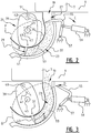
- feeder duct 23 is shown in more detail during normal operation.
- the feeder duct 23 is defined between a feeder duct top wall 35 and feeder duct bottom wall 37.
- the feeder duct top wall 35 provides an upper boundary for the feeder duct 23.
- the feeder duct bottom wall 37 provides a lower boundary for the feeder duct 23.
- feeder means 25 are operable.
- the feeder means 25 include a rotatable drum 39 having sets of tines 41, 43 arranged thereon. In operation the drum 39 is rotated in the direction of arrow B about axis of rotation 45.
- the feeder means 25 further include a schematically shown drive 47.
- the drive 47 is arranged for rotating the drum 39 in the direction of arrow B about axis of rotation 45.
- the drive 47 further includes a mechanism for rotating the respective sets of tines 41, 43 relative to the drum 39 about a respective axis of rotation 49, 51, while the drum 39 is rotated in the direction of arrow B about axis of rotation 45.
- This path of movement may be a fixed path of movement or an adjustable path of movement, wherein the drive 47 comprises a mechanism for adjusting the path of movement of the sets of tines 41, 43, while the drum 39 is rotated in the direction of arrow B about axis of rotation 45.
- the outer ends of the tines 41, 43 are caused to be moved along a path of movement P, Q through the feeder duct 23 in the direction indicated by arrow B, thereby conveying cut crop material that has been conveyed by the cutting unit 31 into the lower end 29 of the feeder duct 23, from the lower end 29 of the feeder duct 23 toward the upper end 27 thereof.
- the feeder means 25 first accumulate a charge of crop material 53 in the feeder duct 23. Thereto, tines 41, 43 are moved through the feeder duct 23 along an accumulating movement path P. While the charge of crop material 53 is being accumulated, crop holding fingers 55 provided at the upper end 27 of the feeder duct 23 extend in the feeder duct 23 in the upper end part thereof to hold back the crop material 53 that is being accumulated. The crop holding fingers 55 thus prevent that said crop material 53 is forced through the opening 19 into the bale chamber 9. Furthermore, while the charge of crop material 53 is being accumulated, the plunger 7 reciprocates in the bale chamber 9, wherein during part of the reciprocating movement, the plunger 7 blocks the opening 19.
- the plunger 7 that reciprocates in the bale chamber 9 is clear from the opening 19 in the bale chamber 9, and the bale chamber 9 is ready to receive the accumulated charge of crop material 53, the crop holding fingers 55 are withdrawn from the the upper end part of the feeder duct 23.
- the crop holding fingers 55 are withdrawn from the the upper end part of the feeder duct 23 by rotating the crop holding fingers 55 in the direction of arrow C (see figure 2 ) about axis of rotation 57 by means of linear actuator 59.
- the outer ends of the tines 43 are caused to be moved along a stuffing movement path Q through the feeder duct 23 in the direction indicated by arrow B, thereby stuffing, i.e. conveying, the accumulated charge of crop material 53 through the opening 19 into the bale chamber 9.
- the crop holding fingers 55 are moved in the direction of arrow D back into their crop holding position wherein they extend in the feeder duct 23 in the upper end part thereof, and the feeder means 25 operate to accumulate a next charge of crop material in the feeder duct 23.
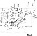
- FIG 4 In figure 4 is shown a situation wherein during accumulation of the charge of crop material 53, a plug 61 of crop material gets stuck in the feeder duct 23 causing the feeding means 25 to become inoperable.
- sensor means 63 are provided that are configured to measure the load on the sets of tines 41, 43.
- the sensor means 63 are connected to a controller 65 that in turn is connected to the actuator 59 of the crop holding fingers 55 and to the drive 47 of the feeder means 25.
- the controller 65 is provided with a processor 67 that compares the measured load on the sets of tines 41, 43 with a predetermined load that is indicative of a plugging of the feeder duct.
- the controller 65 cause the drive 47 of the feeder means 25 to stop operation of the feeder means 25.
- the operation of the feeder means 25 is stopped by stopping the rotation of the drum 39 or by adjusting the path of movement of the outer ends of the tines 41, 43 such that the outer ends do not pass through the feeder duct 23.
- the controller 65 controls the actuator 59 of the crop holding fingers 55 such that the crop holding fingers 55 are moved from the crop holding position in the direction of arrow C into the withdrawn position (shown in figure 5 ) wherein the crop holding fingers 55 do no longer hold back the crop material 53.
- the crop material 53 is allowed to expand and to move into the space S (shown in figure 4 between the crop holding fingers and the bale chamber 9).
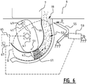
- the controller 65 controls the drive 47 of the feeder means 25 such that the feeder means 25 are caused to resume operation wherein the outer ends of the tines 41 resume movement along the accumulating movement path P through the feeder duct 23 in the direction indicated by arrow B.
- the crop holding fingers 55 are moved in the direction of arrow D back into their crop holding position wherein they extend in the feeder duct 23 in the upper end part thereof, such that the feeder means 25 can accumulate a next charge of crop material in the feeder duct 23.
- the bale chamber 9 provides additional space for the crop material 53 downstream of the plug of crop material 61 to move into. This allows for further reduction of pressure exerted on the stuck plug 61 of crop material at its downstream side and/or pressure build up when moving the plug of crop material and the crop material downstream thereof into the direction of the upper end of the feeder duct indicated by arrow B.
- FIG. 7 is illustrative of an alternative embodiment of the method illustrated by means of figures 4 to 6 , wherein in case during accumulation of the charge of crop material, a plug 61 of crop material 53 gets stuck in the feeder duct 23 causing the feeding means 25 to become inoperable, in addition to withdrawing the crop holding fingers 55 and before causing the feeder means 25 to operate in the feeder duct 23 to dislodge the stuck plug 61 of crop material, the distance a between the top wall 35 and the bottom wall 37 of the feeder duct 23 is increased, while leaving the upper boundary provided by the top wall 35 of the feeder duct and the lower boundary provided by the bottom wall 37 of the feeder duct 23 intact.
- the three sections 37a, 37b, 37c of the bottom wall 37 of the feeder duct 23 are moved back into their original position in the direction indicated by arrow F by means of linear actuators 69 and the crop holding fingers 55 are moved in the direction of arrow D back into their crop holding position by means of actuator 59 wherein they extend in the feeder duct 23 in the upper end part thereof, such that the feeder means 25 can accumulate a next charge of crop material in the feeder duct 23.
Landscapes
- Life Sciences & Earth Sciences (AREA)
- Environmental Sciences (AREA)
- Apparatuses For Bulk Treatment Of Fruits And Vegetables And Apparatuses For Preparing Feeds (AREA)
- Storage Of Harvested Produce (AREA)
- Harvesting Machines For Specific Crops (AREA)
Abstract
Description
- The present invention relates to a method for operation of an agricultural balers, and more specifically to rectangular balers, i.e. balers which produce bales of crop material which are rectangular in side view.
- In
EP0339733 there is disclosed a rectangular baler of basically conventional design in that it comprises a bale chamber or chamber in which a bale of crop material is formed, having an inlet opening formed therein communicating with a feeder duct. In the feeder duct feeder means are operable to accumulate a charge of crop material in the feeder duct and then stuff that accumulated charge into the bale chamber for compression by a reciprocally movable plunger operating within the bale chamber. - The bale chamber has a bottom wall in which the inlet opening is formed. The feeder duct has an upper end facing generally upwardly and communicating with the inlet opening in the bale chamber and a lower end facing generally in a forward direction. The upper boundary and the lower boundary of the feeder duct are formed by a top wall and a bottom wall, respectively, extending between the lower end and the upper end of the feeder duct.
- In the baler disclosed in
EP0339733 the feeder duct is provided with an opening in the bottom wall thereof and with releasable closure means for the opening. The releasable closure means for the opening are in the form of two doors. The doors are hingedly attached to respective opposed edges of the opening in the bottom wall of the feeder duct. A leading or front door, as seen relative to the direction of flow through the feeder duct, is hingedly attached to an edge of a lower end part of the bottom wall. A trailing or rear door is hingedly attached to an edge of an upper end part of the bottom wall. In normal operation of the baler the doors close the opening in the feeder duct. When a plugging of the feeder duct occurs, the feeder means are stopped and the doors are opened, allowing a plug of crop material to discharge onto the ground. Once the plug of crop material has been discharged to the ground, the doors are closed to resume normal operation. - In
US 2012/0186465 , a baler is shown having a stuffer system comprising a precompression chamber and plural stuffer arms. Coupled to the plural stuffer arms is a retractable fork. The stuffer arms pivot about an axis and are driven in a clockwise and counterclockwise shared path by means of a first motive apparatus. The forks of the plural stuffer arms are controlled by a second motive apparatus. These first and second apparatus will thus be able to independently control the fork and stuffer arm. - Although the method for removing a plugging of the feeder duct as described in
EP0339733 by opening the lower boundary of the feeder duct provided by the bottom wall thereof so as to discharge a plug of crop material from the feeder duct through said opening onto the ground has been found satisfactory, it is an object of the present invention to provide an improved method for removing a plugging of the feeder duct. It is in particular an object of the present invention to provide an improved method for removing a plugging of the feeder duct in rectangular balers that are provided with crop holding fingers in the upper end part of the feeder duct. These crop holding fingers are selectively movable between a crop holding position and a withdrawn position. In the crop holding position the crop holding fingers extend in the feeder duct in the upper end part thereof to hold back the crop material while the charge of crop material is being accumulated. In the withdrawn position the crop holding fingers are withdrawn from the upper end part of the feeder duct, i.e. do no longer extend in the feeder duct. In this withdrawn position the crop holding fingers no longer hold the crop material back to allow the accumulated charge of crop material to be stuffed into the bale chamber. - Thereto the method according to the present invention comprises in case of a plug of crop material being stuck in the feeder duct with the crop holding fingers in their crop holding position, moving the crop holding fingers in their withdrawn position and causing the feeder means to operate in the feeder duct with the crop holding fingers in their withdrawn position.
- By withdrawing the crop holding fingers from the upper end part of the feeder duct in case of a plug of crop material being stuck in the feeder duct with in their crop holding position, i.e. while accumulating a charge of crop material in the feeder duct by means of the feeder means, a space in the upper end part of the feeder duct between the crop holding fingers and the bottom wall of the bale chamber comes available for movement of the crop material in the feeder duct in the direction of the upper end thereof. Although the space that comes available by withdrawing the crop holding fingers is relatively small, it allows for the crop material in the feeder duct downstream of the stuck plug of crop material to expand and move a relatively small distance in the direction of the bottom wall of the bale chamber, thereby relieving pressure exerted on the stuck plug of crop material at its downstream side and/or reducing pressure build up on the stuck plug of crop material at its downstream side when subsequently causing the feeder means to operate in the feeder duct with the crop holding fingers in their withdrawn position. When operating the feeder means after moving the crop holding fingers in their withdrawn position the relieved pressure and/or reduced pressure build up on the stuck plug of crop material at its downstream side help to reduce the counter pressure on the stuck plug of crop material at the downstream side thereof when the feeder means engage the crop material on the upstream side of the stuck plug of crop material and force the stuck plug of crop material in the downstream direction, i.e. in the direction of the bale chamber. This allows the feeder means to more effectively exert a force on the stuck plug of crop material in the downstream direction, thereby increasing the chance of moving the stuck plug of crop material in the downstream direction and thus dislodge the stuck plug of crop material. The dislodged plug of crop material can subsequently be removed from the feeder duct by means of the feeder means by transferring the dislodged plug of crop material into the bale chamber. The method according to the invention thus provides an alternative for discharging the plug of crop material onto the ground. This has as an advantage over prior art methods, as for instance described in
EP0339733 , that after removing the plug of crop material, there is no plug of crop material laying on the ground underneath the feeder duct, that, as described inEP0339733 , hinders the doors of the feeder duct to be closed and the baler from being moved. There is no need for the plug of crop material laying on the ground to be removed from underneath the feeder duct for normal operation of the baler to resume. - In a preferred embodiment of the method according to the invention, the method comprises detecting the occurrence of a plugging of the feeder duct and after detecting the occurrence of a plugging of the feeder duct, in case the crop holding fingers are in their crop holding position, moving the crop holding fingers in their withdrawn position and causing the feeder means to operate in the feeder duct with the crop holding fingers in their withdrawn position.
- In an advantageous embodiment thereof, the method comprises for detecting the occurrence of a plugging of the feeder duct, measuring the load on the feeder means during operation thereof in the feeder duct and comparing the measured load with a predetermined load that is indicative of a stuck plug of crop material in the feeder duct.
- In a further advantageous embodiment the method according to the invention comprises in case of a plug of crop material being stuck in the feeder duct in addition to withdrawing the crop holding fingers and before causing the feeder means to operate in the feeder duct, increasing the distance between the top wall and the bottom wall of the feeder duct in at least a part of the feeder duct, while leaving the upper boundary provided by the top wall of the feeder duct and the lower boundary provided by the bottom wall of the feeder duct intact. Increasing the distance between the top wall and the bottom wall of the feeder duct in at least a part of the feeder duct allows for additional space in the feeder duct for relieving pressure on the stuck plug of crop material. In order to allow a plug of crop material plugging a part of the feeder duct to be dislodged and moved by means of the feeder means, the distance between the top wall and the bottom wall of the feeder duct is preferably at least increased in the part of the feeder duct where a plugging has occurred.
- In an advantageous embodiment thereof the distance between the top wall and the bottom wall of the feeder duct is additionally increased in the part of the feeder duct down stream, as seen in the direction of conveying, of the part of the feeder duct where the plugging has occurred. This additional feature helps to relieve pressure exerted on the plug of crop material on the downstream side thereof. Furthermore, this additional feature helps to reduce pressure build up on the stuck plug of crop material at its downstream side in order to reduce the counter pressure on the stuck plug of crop material at the downstream side thereof when the feeder means engage the crop material on the upstream side of the stuck plug of crop material and force the stuck plug of crop material in the downstream direction, i.e. in the direction of the bale chamber. Still further, this additional feature prevents the dislodged plug of crop material to get stuck again while being conveyed by means of the feeder means from the part of the feeder duct where it was dislodged towards the upper end of the feeder duct.
- Preferably, the distance between the top wall and the bottom wall of the feeder duct is increased over substantially the whole length of said down stream part, and more preferably over substantially the whole length of the feeder duct.
- Advantageously, the distance between the top wall and the bottom wall of the feeder duct in at least part of the feeder duct is increased by moving the bottom wall away from the top wall in said at least part of the feeder duct. This is advantageous in that in rectangular balers of conventional design, there is more room available for moving the bottom wall away from the top wall than for moving the top wall away from the bottom wall.
- The accompanying drawings are used to illustrate present non-limitative preferred exemplary embodiments of the present invention. The above stated and other advantages, features and objectives of the invention will become more apparent, and the invention better understood, from the following detailed description when read in combination with the accompanying drawings, in which
-
Figure 1 shows a schematic side view of an embodiment of a baler according to the invention adapted to execute the method according to the invention, drawn and driven by a tractor; -
Figures 2 and 3 show in schematic side view the feeding duct of the baler offigure 1 during normal operation; -
Figures 4 to 6 show in schematic side view the feeding duct of the baler offigure 1 the method according to the invention for removing a stuck plug of crop material from the feeder duct according to a first embodiment; -
Figure 7 shows in schematic side view the feeding duct of the baler offigure 1 an alternative embodiment of the method according to the invention. -
Figure 1 shows a rectangularagricultural baler 1. Baler 1 can be moved forward over ground surface 3 by means of atractor 5. Inbaler 1 is provided with aplunger 7 that during operation is moved reciprocally along a linear path A inbale chamber 9 by means of a crank mechanism 11 connected toplunger 7. Crank mechanism 11 is connected for driving via adrive shaft 13 to the motor oftractor 5. Tractor 5 is provided for this purpose with a power take-off device, also referred to as PTO.Drive shaft 13 connects an output shaft of the PTO oftractor 5 to aninput shaft 15 of crank mechanism 11. Aflywheel 17 is arranged on the input shaft of the crank mechanism. - The
bale chamber 9 has an inlet opening 19 formed in thebottom wall 21 thereof. Afeeder duct 23 communicates with thebale chamber 9 through the inlet opening 19 for charges of crop material to be transferred from thefeeder duct 23 into thebale chamber 9. Feeder means 25 are operable within thefeeder duct 23 to accumulate a charge of crop material therein and then stuff that accumulated charge into thebale chamber 9. Thefeeder duct 23 has anupper end 27 facing generally upwardly and communicating with the inlet opening 19 in thebale chamber 9 and alower end 29 facing generally in a forward direction and communicating with a cuttingunit 31. The cuttingunit 31 is arranged for cutting crop material supplied by a pick-updevice 33 and to convey the cut crop material into thefeeder duct 23. - In
figures 2 and 3 thefeeder duct 23 is shown in more detail during normal operation. Thefeeder duct 23 is defined between a feederduct top wall 35 and feederduct bottom wall 37. The feederduct top wall 35 provides an upper boundary for thefeeder duct 23. The feederduct bottom wall 37 provides a lower boundary for thefeeder duct 23. In thefeeder duct 23 feeder means 25 are operable. The feeder means 25 include arotatable drum 39 having sets oftines drum 39 is rotated in the direction of arrow B about axis ofrotation 45. - The feeder means 25 further include a schematically shown
drive 47. Thedrive 47 is arranged for rotating thedrum 39 in the direction of arrow B about axis ofrotation 45. Thedrive 47 further includes a mechanism for rotating the respective sets oftines drum 39 about a respective axis ofrotation drum 39 is rotated in the direction of arrow B about axis ofrotation 45. This causes the outer ends of thetines drive 47 comprises a mechanism for adjusting the path of movement of the sets oftines drum 39 is rotated in the direction of arrow B about axis ofrotation 45. - During normal operation, the outer ends of the
tines feeder duct 23 in the direction indicated by arrow B, thereby conveying cut crop material that has been conveyed by the cuttingunit 31 into thelower end 29 of thefeeder duct 23, from thelower end 29 of thefeeder duct 23 toward theupper end 27 thereof. - As illustrated by means of
figure 2 , the feeder means 25 first accumulate a charge ofcrop material 53 in thefeeder duct 23. Thereto,tines feeder duct 23 along an accumulating movement path P. While the charge ofcrop material 53 is being accumulated,crop holding fingers 55 provided at theupper end 27 of thefeeder duct 23 extend in thefeeder duct 23 in the upper end part thereof to hold back thecrop material 53 that is being accumulated. Thecrop holding fingers 55 thus prevent that saidcrop material 53 is forced through theopening 19 into thebale chamber 9. Furthermore, while the charge ofcrop material 53 is being accumulated, theplunger 7 reciprocates in thebale chamber 9, wherein during part of the reciprocating movement, theplunger 7 blocks theopening 19. - As illustrated by means of
figure 3 , once the charge ofcrop material 53 has been accumulated, theplunger 7 that reciprocates in thebale chamber 9 is clear from theopening 19 in thebale chamber 9, and thebale chamber 9 is ready to receive the accumulated charge ofcrop material 53, thecrop holding fingers 55 are withdrawn from the the upper end part of thefeeder duct 23. In particular, thecrop holding fingers 55 are withdrawn from the the upper end part of thefeeder duct 23 by rotating thecrop holding fingers 55 in the direction of arrow C (seefigure 2 ) about axis ofrotation 57 by means oflinear actuator 59. Subsequently, the outer ends of thetines 43 are caused to be moved along a stuffing movement path Q through thefeeder duct 23 in the direction indicated by arrow B, thereby stuffing, i.e. conveying, the accumulated charge ofcrop material 53 through theopening 19 into thebale chamber 9. After the charge ofcrop material 53 has been stuffed into thebale chamber 9, thecrop holding fingers 55 are moved in the direction of arrow D back into their crop holding position wherein they extend in thefeeder duct 23 in the upper end part thereof, and the feeder means 25 operate to accumulate a next charge of crop material in thefeeder duct 23. - In
figure 4 is shown a situation wherein during accumulation of the charge ofcrop material 53, aplug 61 of crop material gets stuck in thefeeder duct 23 causing the feeding means 25 to become inoperable. As shown infigure 4 sensor means 63 are provided that are configured to measure the load on the sets oftines controller 65 that in turn is connected to theactuator 59 of thecrop holding fingers 55 and to thedrive 47 of the feeder means 25. Thecontroller 65 is provided with aprocessor 67 that compares the measured load on the sets oftines feeder duct 23 is detected, thecontroller 65 cause thedrive 47 of the feeder means 25 to stop operation of the feeder means 25. The operation of the feeder means 25 is stopped by stopping the rotation of thedrum 39 or by adjusting the path of movement of the outer ends of thetines feeder duct 23. - Subsequently, in order to dislodge the
plug 61 of crop material, thecontroller 65 controls theactuator 59 of thecrop holding fingers 55 such that thecrop holding fingers 55 are moved from the crop holding position in the direction of arrow C into the withdrawn position (shown infigure 5 ) wherein thecrop holding fingers 55 do no longer hold back thecrop material 53. As a result, and as illustrated by means offigure 5 , thecrop material 53 is allowed to expand and to move into the space S (shown infigure 4 between the crop holding fingers and the bale chamber 9). This relieves the pressure exerted on thestuck plug 61 of crop material at its downstream side and provides additional space for theplug 61 of crop material and thecrop material 53 downstream thereof to be moved into the direction of the upper end of thefeeder duct 23 indicated by arrow B (seefigure 5 ) with reduced pressure build up. - Subsequently, the
controller 65 controls thedrive 47 of the feeder means 25 such that the feeder means 25 are caused to resume operation wherein the outer ends of thetines 41 resume movement along the accumulating movement path P through thefeeder duct 23 in the direction indicated by arrow B. As a result of the relieved pressure exerted on thestuck plug 61 of crop material at its downstream side and the additional space for moving the plug of crop material and the crop material downstream thereof into the direction of the upper end of the feeder duct indicated by arrow B with reduced pressure build up, the counter pressure experienced by the outer ends of thetines 41 while exerting force on thestuck plug 61 of crop material at its upstream side, is reduced thereby allowing the outer ends of thetines 41 to dislodge thestuck plug 61 of crop material and continue its accumulating movement path P. This allows the feeder means 25 to resume normal operation, wherein, as illustrated byfigure 6 , once theplunger 7 that reciprocates in thebale chamber 9 is clear from theopening 19 in thebale chamber 9, and thebale chamber 9 is ready to receive the accumulated charge ofcrop material 53, the outer ends of thetines 43 are caused to be moved along the stuffing movement path Q through thefeeder duct 23 in the direction indicated by arrow B, thereby stuffing, i.e. conveying, the accumulated charge ofcrop material 53 including the dislodgedplug 61 of crop material through theopening 19 into thebale chamber 9. After the charge ofcrop material 53 has been stuffed into thebale chamber 9, thecrop holding fingers 55 are moved in the direction of arrow D back into their crop holding position wherein they extend in thefeeder duct 23 in the upper end part thereof, such that the feeder means 25 can accumulate a next charge of crop material in thefeeder duct 23. - In case the
plunger 7 has already cleared theopening 19 when moving thecrop holding fingers 55 from the crop holding position in the direction of arrow C into the withdrawn position in order to provide the additional space S or when resuming operation of the feeder means 25 in order to dislodge the stuck plug ofcrop material 61, thebale chamber 9 provides additional space for thecrop material 53 downstream of the plug ofcrop material 61 to move into. This allows for further reduction of pressure exerted on thestuck plug 61 of crop material at its downstream side and/or pressure build up when moving the plug of crop material and the crop material downstream thereof into the direction of the upper end of the feeder duct indicated by arrow B. - It should be understood that the specific paths of movement of the tines indicated in the
figures 2 to 6 as well as the number of tines of the feeder means are exemplary. -
Figure 7 is illustrative of an alternative embodiment of the method illustrated by means offigures 4 to 6 , wherein in case during accumulation of the charge of crop material, aplug 61 ofcrop material 53 gets stuck in thefeeder duct 23 causing the feeding means 25 to become inoperable, in addition to withdrawing thecrop holding fingers 55 and before causing the feeder means 25 to operate in thefeeder duct 23 to dislodge thestuck plug 61 of crop material, the distance a between thetop wall 35 and thebottom wall 37 of thefeeder duct 23 is increased, while leaving the upper boundary provided by thetop wall 35 of the feeder duct and the lower boundary provided by thebottom wall 37 of thefeeder duct 23 intact. In particular it is schematically shown that threesections feeder duct 23 having overlapping edges are moved from their original position, indicated with the dotted line, away from thetop wall 35 of thefeeder duct 23 in the direction of arrows E by means oflinear actuators 69 that are connected to and controlled by thecontroller 65. As a result additional space S' is provided in thefeeder duct 23 that further relieves the pressure exerted on thestuck plug 61 of crop material and that allows for more movement of thestuck plug 61 of crop material and the crop material downstream 53 thereof. After theplug 61 of crop material has been removed from thefeeder duct 23 by conveying the dislodgedplug 61 of crop material into thebale chamber 9, the threesections bottom wall 37 of thefeeder duct 23 are moved back into their original position in the direction indicated by arrow F by means oflinear actuators 69 and thecrop holding fingers 55 are moved in the direction of arrow D back into their crop holding position by means ofactuator 59 wherein they extend in thefeeder duct 23 in the upper end part thereof, such that the feeder means 25 can accumulate a next charge of crop material in thefeeder duct 23. - Although the principles of the invention have been set forth above with reference to specific embodiments, it must be understood that this description is given solely by way of example and not as limitation to the scope of protection, which is defined by the appended claims.
Claims (4)
- Method for removing a plug (61) of crop material stuck in a feeder duct (23) of a baler (1),
said baler comprising:- a bale chamber (9) having an inlet opening (19) formed therein;- a feeder duct (23) communicating with the bale chamber (9) through the inlet opening (19) for charges of crop material (53) to be transferred from the feeder duct into the bale chamber, wherein the feeder duct (23) has an upper end (27) facing generally upwardly and communicating with the inlet opening (19) in the bale chamber and a lower end (27) facing generally in a forward direction;- a plunger (7) reciprocally movable within the bale chamber (9) to compress successive charges of crop material (53) received from the feeder duct (23) to form a bale;- feeder means (25) operable within the feeder duct to accumulate a charge of crop material therein and then stuff that accumulated charge into the bale chamber (9); and- crop holding fingers (55) provided at the upper end (27) of the feeder duct (23), that are movable between a crop holding position and a withdrawn position, wherein in the crop holding position the crop holding fingers (55) extend in the feeder duct (23) in the upper end part thereof to hold back the crop material (53) while the charge of crop material is being accumulated and in the withdrawn position the crop holding fingers (55) are withdrawn from the upper end part of the feeder duct to allow the accumulated charge of crop material to be stuffed into the bale chamber;wherein the method comprises:- in case of a plug (61) of crop material being stuck in the feeder duct (23) with the crop holding fingers (55) in their crop holding position, moving the crop holding fingers (55) in their withdrawn position and causing the feeder means (25) to operate in the feeder duct (23) with the crop holding fingers (55) in their withdrawn position; and- detecting the occurrence of a plugging of the feeder duct (23) and after detecting the occurrence of a plugging of the feeder duct (23), in case the crop holding fingers (55) are in their crop holding position, moving the crop holding fingers (55) in their withdrawn position and causing the feeder means (25) to operate in the feeder duct with the crop holding fingers in their withdrawn position;characterized in that the method further comprises for detecting the occurrence of a plugging of the feeder duct, measuring the load on the feeder means (25) during operation thereof in the feeder duct (23) and comparing the measured load with a predetermined load that is indicative of a stuck plug (61) of crop material in the feeder duct. - Method according to claim 1, wherein the feeder duct (23) has a top wall (35) and a bottom wall (37) extending between the lower end (29) and the upper end (27) of the feeder duct (23), said top wall providing an upper boundary of the feeder duct and said bottom wall providing a lower boundary of the feeder duct, the method further comprising in case of a plug (61) of crop material being stuck in the feeder duct (23), in addition to withdrawing the crop holding fingers (55) and before causing the feeder means (25) to operate in the feeder duct (23), increasing the distance (a) between the top wall (35) and the bottom wall (37) of the feeder duct (23) in at least a part of the feeder duct, while leaving the upper boundary provided by the top wall of the feeder duct and the lower boundary provided by the bottom wall of the feeder duct intact.
- Method according to claim 2, wherein the distance (a) between the top wall (35) and the bottom wall (37) of the feeder duct (23) is preferably at least increased in the part of the feeder duct where a plugging has occurred, wherein preferably the distance (a) between the top wall (35) and the bottom wall (37) of the feeder duct is additionally increased in the part of the feeder duct (23) downstream, as seen in the direction (B) of conveying, of the part of the feeder duct where the plugging has occurred, and wherein more preferably the distance (a) between the top wall (35) and the bottom wall (37) of the feeder duct (23) is increased over substantially the whole length of said downstream part, and more preferably over substantially the whole length of the feeder duct (23).
- Method according to any of claims 2 or 3, wherein the distance (a) between the top wall (35) and the bottom wall (37) of the feeder duct (23) in at least part of the feeder duct (23) is increased by moving the bottom wall (37) away from the top wall (35) in said at least part of the feeder duct.
Applications Claiming Priority (1)
| Application Number | Priority Date | Filing Date | Title |
|---|---|---|---|
| BE2015/5679A BE1023153B1 (en) | 2015-10-20 | 2015-10-20 | BALING PRESS AND METHOD FOR REMOVING A PROP HARVESTING MATERIAL CONTAINED IN THE BALL PRESS OF A BALING PRESS |
Publications (2)
| Publication Number | Publication Date |
|---|---|
| EP3158859A1 true EP3158859A1 (en) | 2017-04-26 |
| EP3158859B1 EP3158859B1 (en) | 2018-08-15 |
Family
ID=55352947
Family Applications (1)
| Application Number | Title | Priority Date | Filing Date |
|---|---|---|---|
| EP16194841.9A Active EP3158859B1 (en) | 2015-10-20 | 2016-10-20 | A method for removing a plug of crop material stuck in the feeder duct of an agricultural baler |
Country Status (3)
| Country | Link |
|---|---|
| US (1) | US9756790B2 (en) |
| EP (1) | EP3158859B1 (en) |
| BE (1) | BE1023153B1 (en) |
Cited By (3)
| Publication number | Priority date | Publication date | Assignee | Title |
|---|---|---|---|---|
| WO2018109140A1 (en) * | 2016-12-14 | 2018-06-21 | Mchale Engineering | A conveying device and a method for conveying material through a conveying channel |
| BE1025546B1 (en) * | 2017-12-22 | 2019-04-03 | Cnh Industrial Belgium Nv | STRAW HOOK SET-UP FOR AN AGRICULTURAL BALL PRESS |
| EP4494451A1 (en) * | 2023-07-19 | 2025-01-22 | Deere & Company | Square baler implement |
Families Citing this family (5)
| Publication number | Priority date | Publication date | Assignee | Title |
|---|---|---|---|---|
| US11013186B2 (en) * | 2018-09-11 | 2021-05-25 | Deere & Company | Baler with adjustable pre-compression chamber |
| US11013185B2 (en) * | 2018-09-11 | 2021-05-25 | Deere & Company | Baler with adjustable pre-compression chamber |
| EP3662743B1 (en) * | 2018-12-03 | 2023-02-08 | CNH Industrial Belgium NV | An agricultural baler |
| US11382277B2 (en) * | 2020-06-30 | 2022-07-12 | Deere & Company | Large square baler with pre-compression chamber having removeable access panel |
| EP4523517A1 (en) * | 2023-09-18 | 2025-03-19 | Kverneland Group Ravenna S.r.l. | A method for automatic unblocking of a feed intake plug in a baler towed by a tractor and an agricultural system implementing the method |
Citations (9)
| Publication number | Priority date | Publication date | Assignee | Title |
|---|---|---|---|---|
| DE280440C (en) * | 1907-06-19 | 1914-11-14 | ||
| GB2055557A (en) * | 1979-07-06 | 1981-03-11 | Krone Bernhard Gmbh Maschf | Cutting mechanism for agricultural harvesting machines |
| DE8126403U1 (en) * | 1982-01-28 | Klöckner-Humboldt-Deutz AG Zweigniederlassung Fahr, 7702 Gottmadingen | Forage wagons for stalks | |
| EP0339733A1 (en) | 1988-04-28 | 1989-11-02 | New Holland Belgium N.V. | Agricultural baler |
| DE20005965U1 (en) * | 2000-03-31 | 2000-08-10 | Kverneland Gottmadingen GmbH & Co. KG, 78244 Gottmadingen | Cutting unit |
| EP1306002A1 (en) * | 2001-10-25 | 2003-05-02 | Deere & Company | Baler |
| WO2010106038A1 (en) * | 2009-03-17 | 2010-09-23 | Cnh Belgium N.V. | A square baler |
| EP2238825A1 (en) * | 2009-03-31 | 2010-10-13 | Deere & Company | Rectangular baler |
| US20120186465A1 (en) | 2010-12-15 | 2012-07-26 | Agco Corporation | Variable Density Pre-Compression Chamber |
Family Cites Families (9)
| Publication number | Priority date | Publication date | Assignee | Title |
|---|---|---|---|---|
| GB1288100A (en) | 1969-02-10 | 1972-09-06 | ||
| US4106268A (en) * | 1976-11-01 | 1978-08-15 | Hesston Corporation | Method for loading and baling crop material |
| GB8812270D0 (en) * | 1988-05-24 | 1988-06-29 | Ford New Holland Nv | Agricultural baler |
| DE19531240A1 (en) * | 1995-08-25 | 1997-02-27 | Same Spa | Baler, especially self-propelled large baler |
| DE19715280C2 (en) * | 1997-04-12 | 2000-10-19 | Claas Ohg | Piston press for the production of pressed bales from crops |
| US6543342B2 (en) * | 2000-06-29 | 2003-04-08 | New Holland North America, Inc. | Method for determining a value relating to compressing rate of a baler |
| US6651416B2 (en) * | 2002-02-28 | 2003-11-25 | Deere & Company | Large rectangular baler having hydraulically powered functions, and control system therefor |
| DE102004035696A1 (en) * | 2004-07-22 | 2006-03-16 | Deere & Company, Moline | baler |
| BE1020297A3 (en) * | 2011-11-17 | 2013-07-02 | Cnh Belgium Nv | ADJUSTABLE FEED CHANNEL IN A BALL PRESS. |
-
2015
- 2015-10-20 BE BE2015/5679A patent/BE1023153B1/en not_active IP Right Cessation
-
2016
- 2016-10-18 US US15/296,870 patent/US9756790B2/en active Active
- 2016-10-20 EP EP16194841.9A patent/EP3158859B1/en active Active
Patent Citations (9)
| Publication number | Priority date | Publication date | Assignee | Title |
|---|---|---|---|---|
| DE8126403U1 (en) * | 1982-01-28 | Klöckner-Humboldt-Deutz AG Zweigniederlassung Fahr, 7702 Gottmadingen | Forage wagons for stalks | |
| DE280440C (en) * | 1907-06-19 | 1914-11-14 | ||
| GB2055557A (en) * | 1979-07-06 | 1981-03-11 | Krone Bernhard Gmbh Maschf | Cutting mechanism for agricultural harvesting machines |
| EP0339733A1 (en) | 1988-04-28 | 1989-11-02 | New Holland Belgium N.V. | Agricultural baler |
| DE20005965U1 (en) * | 2000-03-31 | 2000-08-10 | Kverneland Gottmadingen GmbH & Co. KG, 78244 Gottmadingen | Cutting unit |
| EP1306002A1 (en) * | 2001-10-25 | 2003-05-02 | Deere & Company | Baler |
| WO2010106038A1 (en) * | 2009-03-17 | 2010-09-23 | Cnh Belgium N.V. | A square baler |
| EP2238825A1 (en) * | 2009-03-31 | 2010-10-13 | Deere & Company | Rectangular baler |
| US20120186465A1 (en) | 2010-12-15 | 2012-07-26 | Agco Corporation | Variable Density Pre-Compression Chamber |
Cited By (6)
| Publication number | Priority date | Publication date | Assignee | Title |
|---|---|---|---|---|
| WO2018109140A1 (en) * | 2016-12-14 | 2018-06-21 | Mchale Engineering | A conveying device and a method for conveying material through a conveying channel |
| US11191216B2 (en) | 2016-12-14 | 2021-12-07 | Mchale Engineering | Conveying device and a method for conveying material, through a conveying channel |
| BE1025546B1 (en) * | 2017-12-22 | 2019-04-03 | Cnh Industrial Belgium Nv | STRAW HOOK SET-UP FOR AN AGRICULTURAL BALL PRESS |
| EP3513647A1 (en) * | 2017-12-22 | 2019-07-24 | CNH Industrial Belgium NV | Strawhook arrangement for an agricultural baler |
| US11528848B2 (en) | 2017-12-22 | 2022-12-20 | Cnh Industrial America Llc | Strawhook arrangement for an agricultural baler |
| EP4494451A1 (en) * | 2023-07-19 | 2025-01-22 | Deere & Company | Square baler implement |
Also Published As
| Publication number | Publication date |
|---|---|
| US9756790B2 (en) | 2017-09-12 |
| BE1023153B1 (en) | 2016-12-02 |
| EP3158859B1 (en) | 2018-08-15 |
| US20170105353A1 (en) | 2017-04-20 |
Similar Documents
| Publication | Publication Date | Title |
|---|---|---|
| EP3158859B1 (en) | A method for removing a plug of crop material stuck in the feeder duct of an agricultural baler | |
| EP3364742B1 (en) | Agricultural baler | |
| CA2989762C (en) | Agricultural baler | |
| EP3158856B1 (en) | Method for preventing or removing a plugging in the feeder duct of an agricultural baler | |
| EP2992753A1 (en) | Harvester with rear active bottom floor | |
| EP3053429A1 (en) | Drop floor with front and rear linkage mechanism | |
| US11140832B2 (en) | Agricultural baler | |
| US8826816B2 (en) | Method for clearing a blockage in the intake duct of a square baler | |
| EP3158855B1 (en) | Rotor feeder unit for agricultural machines and method for operating a rotor feeder | |
| EP2785169B1 (en) | Combined packer and stuffer means | |
| US11602100B2 (en) | Agricultural baler | |
| EP3545752B1 (en) | An agricultural baler | |
| EP3513647B1 (en) | Strawhook arrangement for an agricultural baler |
Legal Events
| Date | Code | Title | Description |
|---|---|---|---|
| PUAI | Public reference made under article 153(3) epc to a published international application that has entered the european phase |
Free format text: ORIGINAL CODE: 0009012 |
|
| STAA | Information on the status of an ep patent application or granted ep patent |
Free format text: STATUS: THE APPLICATION HAS BEEN PUBLISHED |
|
| AK | Designated contracting states |
Kind code of ref document: A1 Designated state(s): AL AT BE BG CH CY CZ DE DK EE ES FI FR GB GR HR HU IE IS IT LI LT LU LV MC MK MT NL NO PL PT RO RS SE SI SK SM TR |
|
| AX | Request for extension of the european patent |
Extension state: BA ME |
|
| STAA | Information on the status of an ep patent application or granted ep patent |
Free format text: STATUS: REQUEST FOR EXAMINATION WAS MADE |
|
| 17P | Request for examination filed |
Effective date: 20171026 |
|
| RBV | Designated contracting states (corrected) |
Designated state(s): AL AT BE BG CH CY CZ DE DK EE ES FI FR GB GR HR HU IE IS IT LI LT LU LV MC MK MT NL NO PL PT RO RS SE SI SK SM TR |
|
| RIC1 | Information provided on ipc code assigned before grant |
Ipc: A01F 15/10 20060101AFI20180116BHEP |
|
| GRAP | Despatch of communication of intention to grant a patent |
Free format text: ORIGINAL CODE: EPIDOSNIGR1 |
|
| STAA | Information on the status of an ep patent application or granted ep patent |
Free format text: STATUS: GRANT OF PATENT IS INTENDED |
|
| INTG | Intention to grant announced |
Effective date: 20180305 |
|
| GRAS | Grant fee paid |
Free format text: ORIGINAL CODE: EPIDOSNIGR3 |
|
| GRAA | (expected) grant |
Free format text: ORIGINAL CODE: 0009210 |
|
| STAA | Information on the status of an ep patent application or granted ep patent |
Free format text: STATUS: THE PATENT HAS BEEN GRANTED |
|
| AK | Designated contracting states |
Kind code of ref document: B1 Designated state(s): AL AT BE BG CH CY CZ DE DK EE ES FI FR GB GR HR HU IE IS IT LI LT LU LV MC MK MT NL NO PL PT RO RS SE SI SK SM TR |
|
| REG | Reference to a national code |
Ref country code: CH Ref legal event code: EP Ref country code: GB Ref legal event code: FG4D Ref country code: AT Ref legal event code: REF Ref document number: 1028648 Country of ref document: AT Kind code of ref document: T Effective date: 20180815 |
|
| REG | Reference to a national code |
Ref country code: IE Ref legal event code: FG4D |
|
| REG | Reference to a national code |
Ref country code: DE Ref legal event code: R096 Ref document number: 602016004770 Country of ref document: DE |
|
| REG | Reference to a national code |
Ref country code: FR Ref legal event code: PLFP Year of fee payment: 3 |
|
| REG | Reference to a national code |
Ref country code: NL Ref legal event code: MP Effective date: 20180815 |
|
| REG | Reference to a national code |
Ref country code: LT Ref legal event code: MG4D |
|
| REG | Reference to a national code |
Ref country code: AT Ref legal event code: MK05 Ref document number: 1028648 Country of ref document: AT Kind code of ref document: T Effective date: 20180815 |
|
| PG25 | Lapsed in a contracting state [announced via postgrant information from national office to epo] |
Ref country code: FI Free format text: LAPSE BECAUSE OF FAILURE TO SUBMIT A TRANSLATION OF THE DESCRIPTION OR TO PAY THE FEE WITHIN THE PRESCRIBED TIME-LIMIT Effective date: 20180815 Ref country code: IS Free format text: LAPSE BECAUSE OF FAILURE TO SUBMIT A TRANSLATION OF THE DESCRIPTION OR TO PAY THE FEE WITHIN THE PRESCRIBED TIME-LIMIT Effective date: 20181215 Ref country code: RS Free format text: LAPSE BECAUSE OF FAILURE TO SUBMIT A TRANSLATION OF THE DESCRIPTION OR TO PAY THE FEE WITHIN THE PRESCRIBED TIME-LIMIT Effective date: 20180815 Ref country code: SE Free format text: LAPSE BECAUSE OF FAILURE TO SUBMIT A TRANSLATION OF THE DESCRIPTION OR TO PAY THE FEE WITHIN THE PRESCRIBED TIME-LIMIT Effective date: 20180815 Ref country code: GR Free format text: LAPSE BECAUSE OF FAILURE TO SUBMIT A TRANSLATION OF THE DESCRIPTION OR TO PAY THE FEE WITHIN THE PRESCRIBED TIME-LIMIT Effective date: 20181116 Ref country code: NO Free format text: LAPSE BECAUSE OF FAILURE TO SUBMIT A TRANSLATION OF THE DESCRIPTION OR TO PAY THE FEE WITHIN THE PRESCRIBED TIME-LIMIT Effective date: 20181115 Ref country code: NL Free format text: LAPSE BECAUSE OF FAILURE TO SUBMIT A TRANSLATION OF THE DESCRIPTION OR TO PAY THE FEE WITHIN THE PRESCRIBED TIME-LIMIT Effective date: 20180815 Ref country code: AT Free format text: LAPSE BECAUSE OF FAILURE TO SUBMIT A TRANSLATION OF THE DESCRIPTION OR TO PAY THE FEE WITHIN THE PRESCRIBED TIME-LIMIT Effective date: 20180815 Ref country code: LT Free format text: LAPSE BECAUSE OF FAILURE TO SUBMIT A TRANSLATION OF THE DESCRIPTION OR TO PAY THE FEE WITHIN THE PRESCRIBED TIME-LIMIT Effective date: 20180815 Ref country code: BG Free format text: LAPSE BECAUSE OF FAILURE TO SUBMIT A TRANSLATION OF THE DESCRIPTION OR TO PAY THE FEE WITHIN THE PRESCRIBED TIME-LIMIT Effective date: 20181115 |
|
| PG25 | Lapsed in a contracting state [announced via postgrant information from national office to epo] |
Ref country code: LV Free format text: LAPSE BECAUSE OF FAILURE TO SUBMIT A TRANSLATION OF THE DESCRIPTION OR TO PAY THE FEE WITHIN THE PRESCRIBED TIME-LIMIT Effective date: 20180815 Ref country code: HR Free format text: LAPSE BECAUSE OF FAILURE TO SUBMIT A TRANSLATION OF THE DESCRIPTION OR TO PAY THE FEE WITHIN THE PRESCRIBED TIME-LIMIT Effective date: 20180815 Ref country code: AL Free format text: LAPSE BECAUSE OF FAILURE TO SUBMIT A TRANSLATION OF THE DESCRIPTION OR TO PAY THE FEE WITHIN THE PRESCRIBED TIME-LIMIT Effective date: 20180815 |
|
| PG25 | Lapsed in a contracting state [announced via postgrant information from national office to epo] |
Ref country code: RO Free format text: LAPSE BECAUSE OF FAILURE TO SUBMIT A TRANSLATION OF THE DESCRIPTION OR TO PAY THE FEE WITHIN THE PRESCRIBED TIME-LIMIT Effective date: 20180815 Ref country code: ES Free format text: LAPSE BECAUSE OF FAILURE TO SUBMIT A TRANSLATION OF THE DESCRIPTION OR TO PAY THE FEE WITHIN THE PRESCRIBED TIME-LIMIT Effective date: 20180815 Ref country code: CZ Free format text: LAPSE BECAUSE OF FAILURE TO SUBMIT A TRANSLATION OF THE DESCRIPTION OR TO PAY THE FEE WITHIN THE PRESCRIBED TIME-LIMIT Effective date: 20180815 Ref country code: EE Free format text: LAPSE BECAUSE OF FAILURE TO SUBMIT A TRANSLATION OF THE DESCRIPTION OR TO PAY THE FEE WITHIN THE PRESCRIBED TIME-LIMIT Effective date: 20180815 Ref country code: PL Free format text: LAPSE BECAUSE OF FAILURE TO SUBMIT A TRANSLATION OF THE DESCRIPTION OR TO PAY THE FEE WITHIN THE PRESCRIBED TIME-LIMIT Effective date: 20180815 |
|
| REG | Reference to a national code |
Ref country code: DE Ref legal event code: R097 Ref document number: 602016004770 Country of ref document: DE |
|
| PG25 | Lapsed in a contracting state [announced via postgrant information from national office to epo] |
Ref country code: DK Free format text: LAPSE BECAUSE OF FAILURE TO SUBMIT A TRANSLATION OF THE DESCRIPTION OR TO PAY THE FEE WITHIN THE PRESCRIBED TIME-LIMIT Effective date: 20180815 Ref country code: SK Free format text: LAPSE BECAUSE OF FAILURE TO SUBMIT A TRANSLATION OF THE DESCRIPTION OR TO PAY THE FEE WITHIN THE PRESCRIBED TIME-LIMIT Effective date: 20180815 Ref country code: SM Free format text: LAPSE BECAUSE OF FAILURE TO SUBMIT A TRANSLATION OF THE DESCRIPTION OR TO PAY THE FEE WITHIN THE PRESCRIBED TIME-LIMIT Effective date: 20180815 |
|
| PLBE | No opposition filed within time limit |
Free format text: ORIGINAL CODE: 0009261 |
|
| STAA | Information on the status of an ep patent application or granted ep patent |
Free format text: STATUS: NO OPPOSITION FILED WITHIN TIME LIMIT |
|
| PG25 | Lapsed in a contracting state [announced via postgrant information from national office to epo] |
Ref country code: MC Free format text: LAPSE BECAUSE OF FAILURE TO SUBMIT A TRANSLATION OF THE DESCRIPTION OR TO PAY THE FEE WITHIN THE PRESCRIBED TIME-LIMIT Effective date: 20180815 Ref country code: LU Free format text: LAPSE BECAUSE OF NON-PAYMENT OF DUE FEES Effective date: 20181020 |
|
| 26N | No opposition filed |
Effective date: 20190516 |
|
| REG | Reference to a national code |
Ref country code: IE Ref legal event code: MM4A |
|
| PG25 | Lapsed in a contracting state [announced via postgrant information from national office to epo] |
Ref country code: SI Free format text: LAPSE BECAUSE OF FAILURE TO SUBMIT A TRANSLATION OF THE DESCRIPTION OR TO PAY THE FEE WITHIN THE PRESCRIBED TIME-LIMIT Effective date: 20180815 |
|
| PG25 | Lapsed in a contracting state [announced via postgrant information from national office to epo] |
Ref country code: IE Free format text: LAPSE BECAUSE OF NON-PAYMENT OF DUE FEES Effective date: 20181020 |
|
| PG25 | Lapsed in a contracting state [announced via postgrant information from national office to epo] |
Ref country code: MT Free format text: LAPSE BECAUSE OF NON-PAYMENT OF DUE FEES Effective date: 20181020 |
|
| PG25 | Lapsed in a contracting state [announced via postgrant information from national office to epo] |
Ref country code: TR Free format text: LAPSE BECAUSE OF FAILURE TO SUBMIT A TRANSLATION OF THE DESCRIPTION OR TO PAY THE FEE WITHIN THE PRESCRIBED TIME-LIMIT Effective date: 20180815 |
|
| PG25 | Lapsed in a contracting state [announced via postgrant information from national office to epo] |
Ref country code: PT Free format text: LAPSE BECAUSE OF FAILURE TO SUBMIT A TRANSLATION OF THE DESCRIPTION OR TO PAY THE FEE WITHIN THE PRESCRIBED TIME-LIMIT Effective date: 20180815 |
|
| REG | Reference to a national code |
Ref country code: CH Ref legal event code: PL |
|
| PG25 | Lapsed in a contracting state [announced via postgrant information from national office to epo] |
Ref country code: MK Free format text: LAPSE BECAUSE OF NON-PAYMENT OF DUE FEES Effective date: 20180815 Ref country code: CY Free format text: LAPSE BECAUSE OF FAILURE TO SUBMIT A TRANSLATION OF THE DESCRIPTION OR TO PAY THE FEE WITHIN THE PRESCRIBED TIME-LIMIT Effective date: 20180815 Ref country code: HU Free format text: LAPSE BECAUSE OF FAILURE TO SUBMIT A TRANSLATION OF THE DESCRIPTION OR TO PAY THE FEE WITHIN THE PRESCRIBED TIME-LIMIT; INVALID AB INITIO Effective date: 20161020 |
|
| PG25 | Lapsed in a contracting state [announced via postgrant information from national office to epo] |
Ref country code: CH Free format text: LAPSE BECAUSE OF NON-PAYMENT OF DUE FEES Effective date: 20191031 Ref country code: LI Free format text: LAPSE BECAUSE OF NON-PAYMENT OF DUE FEES Effective date: 20191031 |
|
| REG | Reference to a national code |
Ref country code: DE Ref legal event code: R082 Ref document number: 602016004770 Country of ref document: DE Representative=s name: KROHER STROBEL RECHTS- UND PATENTANWAELTE PART, DE |
|
| PGFP | Annual fee paid to national office [announced via postgrant information from national office to epo] |
Ref country code: DE Payment date: 20251028 Year of fee payment: 10 |
|
| PGFP | Annual fee paid to national office [announced via postgrant information from national office to epo] |
Ref country code: GB Payment date: 20251021 Year of fee payment: 10 |
|
| PGFP | Annual fee paid to national office [announced via postgrant information from national office to epo] |
Ref country code: IT Payment date: 20251024 Year of fee payment: 10 |
|
| PGFP | Annual fee paid to national office [announced via postgrant information from national office to epo] |
Ref country code: FR Payment date: 20251027 Year of fee payment: 10 |
|
| PGFP | Annual fee paid to national office [announced via postgrant information from national office to epo] |
Ref country code: BE Payment date: 20251027 Year of fee payment: 10 |