EP3158858A1 - Agricultural baler and method for configuring an agricultural baler - Google Patents
Agricultural baler and method for configuring an agricultural baler Download PDFInfo
- Publication number
- EP3158858A1 EP3158858A1 EP16194834.4A EP16194834A EP3158858A1 EP 3158858 A1 EP3158858 A1 EP 3158858A1 EP 16194834 A EP16194834 A EP 16194834A EP 3158858 A1 EP3158858 A1 EP 3158858A1
- Authority
- EP
- European Patent Office
- Prior art keywords
- tine
- tines
- crop material
- feeder
- bale chamber
- Prior art date
- Legal status (The legal status is an assumption and is not a legal conclusion. Google has not performed a legal analysis and makes no representation as to the accuracy of the status listed.)
- Granted
Links
Images



Classifications
-
- A—HUMAN NECESSITIES
- A01—AGRICULTURE; FORESTRY; ANIMAL HUSBANDRY; HUNTING; TRAPPING; FISHING
- A01D—HARVESTING; MOWING
- A01D89/00—Pick-ups for loaders, chaff-cutters, balers, field-threshers, or the like, i.e. attachments for picking-up hay or the like field crops
- A01D89/001—Pick-up systems
- A01D89/002—Rotors
-
- A—HUMAN NECESSITIES
- A01—AGRICULTURE; FORESTRY; ANIMAL HUSBANDRY; HUNTING; TRAPPING; FISHING
- A01F—PROCESSING OF HARVESTED PRODUCE; HAY OR STRAW PRESSES; DEVICES FOR STORING AGRICULTURAL OR HORTICULTURAL PRODUCE
- A01F15/00—Baling presses for straw, hay or the like
- A01F15/08—Details
- A01F15/10—Feeding devices for the crop material e.g. precompression devices
- A01F15/101—Feeding at right angles to the compression stroke
-
- A—HUMAN NECESSITIES
- A01—AGRICULTURE; FORESTRY; ANIMAL HUSBANDRY; HUNTING; TRAPPING; FISHING
- A01F—PROCESSING OF HARVESTED PRODUCE; HAY OR STRAW PRESSES; DEVICES FOR STORING AGRICULTURAL OR HORTICULTURAL PRODUCE
- A01F15/00—Baling presses for straw, hay or the like
- A01F15/04—Plunger presses
- A01F15/042—Plungers
-
- A—HUMAN NECESSITIES
- A01—AGRICULTURE; FORESTRY; ANIMAL HUSBANDRY; HUNTING; TRAPPING; FISHING
- A01F—PROCESSING OF HARVESTED PRODUCE; HAY OR STRAW PRESSES; DEVICES FOR STORING AGRICULTURAL OR HORTICULTURAL PRODUCE
- A01F15/00—Baling presses for straw, hay or the like
- A01F15/08—Details
- A01F15/10—Feeding devices for the crop material e.g. precompression devices
-
- A—HUMAN NECESSITIES
- A01—AGRICULTURE; FORESTRY; ANIMAL HUSBANDRY; HUNTING; TRAPPING; FISHING
- A01F—PROCESSING OF HARVESTED PRODUCE; HAY OR STRAW PRESSES; DEVICES FOR STORING AGRICULTURAL OR HORTICULTURAL PRODUCE
- A01F15/00—Baling presses for straw, hay or the like
- A01F15/08—Details
- A01F15/10—Feeding devices for the crop material e.g. precompression devices
- A01F15/101—Feeding at right angles to the compression stroke
- A01F2015/102—Feeding at right angles to the compression stroke the pressing chamber is fed from the bottom side
Definitions
- the present invention relates to agricultural balers, and more specifically to balers of the traditional rectangular type, i.e. balers which produce bales of crop material which are rectangular in side view.
- the present invention further relates to a baler system comprising an agricultural baler, a method for configuring an agricultural baler, as well as to a method for baling.
- a baler of basically conventional design in that it comprises a bale chamber or chamber in which a bale of crop material is formed, having an inlet opening formed therein communicating with a feeder duct in which charges of crop material are accumulated which subsequently are transferred or stuffed in the bale chamber for compression by a reciprocally moveable plunger operating within the bale chamber.
- feeder means are operable to accumulate a charge of crop material therein and then stuff that accumulated charge into the bale chamber.
- the feeder means include two tine bars each rotatable about its own axis and about an offset axis. The tine bars are rotatable mounted on a tine bar holding member for rotation about their own axis.
- the tine bar holding member is rotatable about the offset axis. Both tine bars have mounted thereon two sets of tines. One of the tine bars has two sets of packer tines mounted thereon, the sets being angularly offset over 180°, while the other one of the tine bars has a set of packer tines and a set of longer stuffer tines mounted thereon, the sets being angularly offset over 180°. In operation the tine bars are rotated about the offset axis in a direction of rotation while the tine bars are rotated about their respective own axis in a direction of rotation opposite to the direction of rotation of the tine bars about the offset axis.
- the packer tines are moved through the feeder duct along an accumulating movement path wherein the packer tines move crop material from the lower end of the feeder duct toward the upper end of the feeder duct in order to accumulate a charge of crop material at the upper end of the feeder duct.
- the packer tines pack the crop material together in order to form a pre-compressed charge of crop material at the end of the feeder duct.
- the stuffer tines are moved through the feeder duct along a stuffing movement path wherein the stuffer tines stuff, i.e. transfer, the accumulated charge of crop material into the bale chamber.
- the packer tines and the stuffer tines have a plate shaped leading face that is pushed against the crop material.
- FIG. 6 In US 6,425,234 , another baler is shown having a rotary conveyor which rotates about an axis of rotation.
- the rotary conveyer has rakes which have axes extending approximately parallel to the axis of rotation of the rotor and will convey harvested crop through a supply channel to the baling channel.
- the rakes can be swiveled about their rake axes under the control of curves.
- One of the rakes will function as a conveying rake while another one will function as a supply rake, depending on the degree of filling of the supply channel.
- the supply rake is guided in a curved path which can be moved from a conveying position into a supplying position, whereas the conveying rakes are guided in an immovable curved path.
- the object of the present invention to provide an improved baler.
- the baler comprises a bale chamber; a feeder duct communicating with the bale chamber for charges of crop material to be transferred from the feeder duct into the bale chamber; a plunger reciprocally moveable within the bale chamber to compress successive charges of crop material received from the feeder duct to form a bale; and feeder means operable within the feeder duct to accumulate a charge of crop material therein and then stuff that accumulated charge into the bale chamber, wherein the feeder means comprise at least one first tine and at least one second tine, each having a leading face for engaging the crop material.
- the width of frontal area of the leading face of the second tine is smaller than the width of the frontal area of the leading face of the first tine.
- at least the first tine comprises a tine body having mounted thereon a plate, said plate defining the leading face having the frontal area with the larger width.
- the at least one second tine will, as a result of having a leading face with a frontal area that has a smaller width, rather cut into the crop material than push the crop material forward, thereby providing a reduced pushing effect relative to the at least one first tine.
- a first tine can provide a certain full pushing effect while a second tine can provide a reduced pushing effect.
- the feeder means comprise at least two tine bars each having mounted thereon a set of tines.
- the feeder means comprise at least two tine bars each having mounted thereon a set of tines, wherein the set of tines of at least one of said tine bars comprises at least one first tines and the set of tines of at least an other one of said tine bars comprises at least one second tine.
- each of the two tine bars is rotatable about its own axis and about an offset axis.
- the tine bars are rotatable mounted on a tine bar holding member for rotation about their own axis.
- the tine bar holding member is rotatable about the offset axis.
- the feeder means are configured to cause the tine bars to rotate about their respective own axis when the tine bar holding member is rotated about the offset axis such that the tines of the tine bars are caused to move along a path of movement.
- the feeder means are configured to cause the tines of said tine bar having mounted thereon a set of tines comprising at least one first tine to move at least along a stuffing movement path
- the feeder means are configured to cause the tines of said tine bar having mounted thereon a set of tines comprising at least one second tine to move along an accumulating movement path.
- the set of tines of said tine bar that is caused to move at least along a stuffing movement path consists of first tines. This embodiment provides stuffing with full pushing effect along the whole length of one of the tine bars, and accumulating with at least one tine bar having reduced pushing effect along at least part of the length thereof.
- the feeder means comprise a tine bar having mounted thereon a set of tines, wherein said set of tines comprises at least one first tine and at least one second tine.
- said set of tines comprises at least one first tine and at least one second tine.
- the set of tines of the tine bar having mounted thereon at least one first tine and at least one second tine comprises a plurality of first tines and a plurality of second tines, wherein the first tines and second tines are mounted alternatingly along the length of said tine bar.
- said set of tines comprises a plurality of first tines and a plurality of second tines, wherein groups of first tines and groups of second tines are mounted alternatingly along the length of said tine bar.
- the feeder means are configured to cause the tines of said tine bar having mounted thereon a set of tines comprising at least one first tine and at least one second tine to move through the feeder duct along an accumulating movement path.
- first and second tines on a tine bar can also help to increase homogeneity while stuffing a charge of crop material into the bale chamber by reducing the pushing effect on parts of the charge of crop material that would otherwise be subjected to a relatively high increase in density during the stuffing.
- the feeder means comprise at least two tine bars each having mounted thereon a set of tines, wherein the set of tines of at least one of said tine bars consists of first tines and the set of tines of at least an other one of said tine bars comprises at least one second tine.
- the reduced pushing effect is not effectuated while the tines of at least one of the tine bars is moved through the feeder duct.
- the feeder means are configured to cause the tines of said tine bar having mounted thereon a set of tines consisting of first tines to move at least along a stuffing movement path.
- This embodiment provides stuffing with full pushing effect along the whole length of one of the tine bars, and accumulating with at least one tine bar having reduced pushing effect along at least part of the length thereof.
- the set of tines of at least one tine bar consists of first tines, whereas the set of tines of at least another one of the tine bars consists of second tines.
- at least one of the tine bars provides stuffing with full pushing effect, while at least one other tine bar provides packing with reduced pushing effect.
- the feeder means comprise a plurality of tine bodies provided with an arrangement for removable mounting plates thereon for providing said tine bodies with said leading face.
- This allows for all tines of the baler to have the same tine body, wherein for instance the first tines have a plate mounted thereon while the second tines have no plate mounted thereon.
- This also allows for exchanging plates on a tine body, and thus for selectively configuring a tine body to be a first tine or a second tine depending on the desired effect.
- At least the second tine comprises a tine body having mounted thereon a plate, said plate defining the leading face having frontal area with the smaller width, wherein the width of the plate of the second tine is at least the width of the tine body of the second tine.
- a baler system comprises a baler comprising a bale chamber; a feeder duct communicating with the bale chamber for charges of crop material to be transferred from the feeder duct into the bale chamber; a plunger reciprocally moveable within the bale chamber to compress successive charges of crop material received from the feeder duct to form a bale; and feeder means operable within the feeder duct to accumulate a charge of crop material therein and then stuff that accumulated charge into the bale chamber; wherein the feeder means comprise a plurality of tine bodies provided with an arrangement for mounting plates thereon for providing said tine bodies with a leading face.
- the baler system comprises a plurality of first plates and a plurality of second plates configured to be mounted on the tine bodies of said baler for providing said leading face, wherein the width of the frontal area of the leading face defined by the second plates is smaller than the width of the frontal area of the leading face provided by the first plates.
- the present invention further relates to a method for configuring a baler, said baler comprising a bale chamber; a feeder duct communicating with the bale chamber for charges of crop material to be transferred from the feeder duct into the bale chamber; a plunger reciprocably moveable within the bale chamber to compress successive charges of crop material received from the feeder duct to form a bale; and feeder means operable within the feeder duct to accumulate a charge of crop material therein and then stuff that accumulated charge into the bale chamber; wherein the feeder means comprise at least one first tine body and at least one second tine body.
- the method according to the invention for configuring said baler comprises mounting on said first tine body a first plate and mounting on said second tine body a second plate, wherein the width of the frontal area of the leading face defined by the second plate is smaller than the width of the frontal area of the leading face provided by the first plate.
- the method for baling comprises accumulating a charge of crop material in a feeder duct; stuffing an accumulated charge of crop material into a bale chamber; and compressing successive charges of crop material in the bale chamber to form a bale. Either or both accumulating and stuffing is performed using at least one first tine and at least one second tine, each having a leading face for engaging the crop material, wherein the width of the frontal area of the leading face of the second tine is smaller than the width of the frontal area of the leading face of the first tine.
- FIG 1 shows a rectangular agricultural baler 1.
- Baler 1 can be moved forward over ground surface 3 by means of a tractor 5.
- Baler 1 is provided with a plunger 7 that during operation is moved reciprocally along a linear path "Z" in bale chamber 9 by means of a crank mechanism 11 connected to plunger 7.
- Crank mechanism 11 is connected for driving via a drive shaft 13 to the motor of tractor 5.
- Tractor 5 is provided for this purpose with a power take-off device, also referred to as PTO.
- Drive shaft 13 connects an output shaft of the PTO of tractor 5 to an input shaft 15 of crank mechanism 11.
- a flywheel 17 is arranged on the input shaft of the crank mechanism.
- the bale chamber 9 has an inlet opening 19 formed in the bottom wall 21 thereof.
- a feeder duct 23 communicates with the bale chamber 9 through the inlet opening 19 for charges of crop material to be transferred from the feeder duct 23 into the bale chamber 9.
- Feeder means 25 are operable within the feeder duct 23 to accumulate a charge of crop material therein and then stuff that accumulated charge into the bale chamber 9.
- the feeder duct 23 has an upper end 27 facing generally upwardly and communicating with the inlet opening 19 in the bale chamber 9 and a lower end 29 facing generally in a forward direction and communicating with a pickup unit 31.
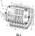
- FIGS. 2 and 3 a part of the feeder duct 23 is shown as well as the feeder means 25.
- the feeder duct 23 is formed between an upper wall 33 and a lower wall 35. In figure 2 only the rear part of the lower wall 35 of the feeder duct 23 is shown.
- the feeder means 25 are shown with a tine bar holding member formed by drum 37 having rotatable mounted thereon a first tine bar 39 and a second tine bar 41. Each tine bar 39, 41 is rotatable about its own axis 47, 49, respectively.
- the first tine bar 39 has mounted thereon a first set of tines 43.
- the second tine bar 41 has mounted thereon a second set of tines 45.
- the drum 37 is rotatable mounted on a part of a frame of the baler 1, such that the tine bars 39, 41 are rotatable about a common offset axis 51, being the axis of rotation of the drum 37.
- first and second tine bar 39, 41 are identical and each have mounted thereon tine bodies 53.
- the tine bodies 53 are distributed along the length of the tine bar 39, 41 with a distance "a" between adjacent tine bodies 53.
- Each tine body 53 is provided with a mounting arrangement in the form of threaded holes 55. As shown in figures 5 and 6 , the threaded holes 55 allow for mounting plates 57, 59 on the tine body 53 for providing either a first tine 61 or a second tine 63.
- a first tine 61 is shown. Said first tine 61 is provided with a first plate 57 having a width "W 1 " that is larger than the width "W 0 " of the tine body 53.
- a second tine 63 is shown.
- Said second tine 63 is provided with a second plate 59 having a width "W 2 " that corresponds to the width "W 0 " of the tine body 53 and that is thus smaller than the width "W 1 " of the first tine 61.
- the lengths "L 1 " and “L 2 " of the first plate 57 and second plate 59 are the same.
- the area “A 1 " of the front face of the first plate 57 is larger than the area “A 2 " of the front face of the second plate 59.
- feeder means 25 as shown in figure 2 to 6 , by rotating the drum 37 in the direction of arrow B while causing the first tine bar and second tine bar to rotate about their respective own axis of rotation relative to the drum 37, it is possible to cause the first set of tines 43 and the second set of tines 45 to follow a path of movement through the feeder duct 23.
- the second set of tines 45 it is for instance possible to cause the second set of tines 45 to follow an accumulating movement path P each full rotation of the drum 37 about its axis 51 of rotation, while causing the first set of tines 43 to follow a stuffing movement path Q each full rotation of the drum 37 about its axis 51 of rotation. While following the accumulating movement path P the tines of the second set of tines 45 engage crop material at the lower end 29 of the feeder duct and move crop material in the direction of the upper end 27 of the feeder duct 23 in order to accumulate a charge of crop material in the feeder duct 23.
- Each full rotation of the drum 37 about its axis 51 of rotation first a charge of crop material is being accumulated by tines of the second set of tines 45 moving along accumulating movement path P through the feeder duct 23, and subsequently the accumulated charge of crop material is transferred into the bale chamber 9 by tines of the first set of tines 43 moving along stuffing movement path Q through the feeder duct 23.
- FIGS 8 and 9 an exemplary embodiment of tine arrangements according to the present invention is shown for the feeder means shown in figure 7 .
- the tines of the first set of tines 43 that is caused to move along the stuffing movement path Q are all first tines 61 as shown in figure 5 , i.e. each being provided with a first plate 57. While moved through the feeder duct 23 along the stuffing movement path Q, the leading face of the first tines 61 defined by the plates 57 engages crop material and pushes the crop material forward thereby providing a pushing effect.
- the second set of tines 45 that is caused to move along the accumulating movement path P includes both first tines 61 as shown in figure 5 , each being provided with a first plate 57, and second tines 63, as shown in figure 6 , each being provided with a second plate 59.
- first tines 61 and single second tines 63 are alternatingly mounted on the second tine bar 41 along the length thereof.
- the first tines 61 have a leading face having a frontal area A 1 defined by the first plate 57 that has a larger width W 1 than the width W 2 of the frontal area A 2 of the leading face provided by the second plates 59 of the second tines 63.
- the leading face of the first tines 61 defined by the plates 57 engages crop material and pushes the crop material forward thereby providing a certain full pushing effect, while the leading face of the second tines 63, as a result of having a frontal area having a smaller width W 2 , provides a reduced pushing effect.
- the second set of tines 45 includes three groups of tines G 1 , G 2 , G 3 that are alternatingly mounted on the second tine bar 41 along the length thereof.
- Groups G 1 and G 3 each consist of first tines 61 having the frontal area A 1 with the larger width W 1 .
- Group G 2 consists of second tines 63 having the frontal area A2 with the smaller width W 2 .
- the second set of tines 43 includes three groups of tines G 4 , G 5 , G 6 that are alternatingly mounted on the second tine bar 41 along the length thereof.
- Group G 4 and G 6 each consist of second tines 63 having the frontal area A 2 with the smaller width W 2 .
- Group G 5 consists of first tines 61 having the frontal area A 1 with the larger width W 1 .
- FIG 12 it is shown that it is also possible with the feeder means 25 as shown in figure 2 to cause the second set of tines 45 to move along an accumulating movement path P each full rotation of the drum 37 about its axis 51 of rotation, while causing the first set of tines 43 to move alternatingly along an accumulating movement path Q 1 and a stuffing movement path Q 2 . While following an accumulating movement path P the tines of the second set of tines 45 engage crop material at the lower end 29 of the feeder duct and move crop material in the direction of the upper end 27 of the feeder duct 23 in order to accumulate a charge of crop material in the feeder duct 23.
- tines are moved through the feeder duct 2 following said paths in accordance with the sequence P, Q 1 , P, Q 2 .
- a charge of crop material is being accumulated during three accumulating movements of tines through the feeder duct 23, and subsequently the accumulated charge of crop material is transferred into the bale chamber 9 during a stuffing movement of tines through the feeder duct 23.
- the tines of the first set of tines 43 are all first tines 61 as shown in figure 5 , i.e. tines that are each being provided with a first plate 57.
- the tines of the second set of tines 45 are all second tines 63 as shown in figure 6 , i.e. tines that are each being provided with a second plate 59.
- tine arrangement shown in figures 13 and 14 is particularly effective in combination with the paths of movement shown in figure 12
- exemplary embodiments of tine arrangements in accordance with the invention described herein above under reference to figures 8 to 11 are also effective in combination with the paths of movement shown in figure 12 .
Landscapes
- Life Sciences & Earth Sciences (AREA)
- Environmental Sciences (AREA)
- Apparatuses For Bulk Treatment Of Fruits And Vegetables And Apparatuses For Preparing Feeds (AREA)
- Harvesting Machines For Specific Crops (AREA)
Abstract
Description
- The present invention relates to agricultural balers, and more specifically to balers of the traditional rectangular type, i.e. balers which produce bales of crop material which are rectangular in side view. The present invention further relates to a baler system comprising an agricultural baler, a method for configuring an agricultural baler, as well as to a method for baling.
- In
EP0236578 there is disclosed a baler of basically conventional design in that it comprises a bale chamber or chamber in which a bale of crop material is formed, having an inlet opening formed therein communicating with a feeder duct in which charges of crop material are accumulated which subsequently are transferred or stuffed in the bale chamber for compression by a reciprocally moveable plunger operating within the bale chamber. Within the feeder duct feeder means are operable to accumulate a charge of crop material therein and then stuff that accumulated charge into the bale chamber. In this particular baler, the feeder means include two tine bars each rotatable about its own axis and about an offset axis. The tine bars are rotatable mounted on a tine bar holding member for rotation about their own axis. The tine bar holding member is rotatable about the offset axis. Both tine bars have mounted thereon two sets of tines. One of the tine bars has two sets of packer tines mounted thereon, the sets being angularly offset over 180°, while the other one of the tine bars has a set of packer tines and a set of longer stuffer tines mounted thereon, the sets being angularly offset over 180°. In operation the tine bars are rotated about the offset axis in a direction of rotation while the tine bars are rotated about their respective own axis in a direction of rotation opposite to the direction of rotation of the tine bars about the offset axis. The packer tines are moved through the feeder duct along an accumulating movement path wherein the packer tines move crop material from the lower end of the feeder duct toward the upper end of the feeder duct in order to accumulate a charge of crop material at the upper end of the feeder duct. The packer tines pack the crop material together in order to form a pre-compressed charge of crop material at the end of the feeder duct. The stuffer tines are moved through the feeder duct along a stuffing movement path wherein the stuffer tines stuff, i.e. transfer, the accumulated charge of crop material into the bale chamber. For accumulating and stuffing, the packer tines and the stuffer tines have a plate shaped leading face that is pushed against the crop material. - In
US 6,425,234 , another baler is shown having a rotary conveyor which rotates about an axis of rotation. The rotary conveyer has rakes which have axes extending approximately parallel to the axis of rotation of the rotor and will convey harvested crop through a supply channel to the baling channel. The rakes can be swiveled about their rake axes under the control of curves. One of the rakes will function as a conveying rake while another one will function as a supply rake, depending on the degree of filling of the supply channel. The supply rake is guided in a curved path which can be moved from a conveying position into a supplying position, whereas the conveying rakes are guided in an immovable curved path. - The object of the present invention to provide an improved baler.
- The baler according to the invention comprises a bale chamber; a feeder duct communicating with the bale chamber for charges of crop material to be transferred from the feeder duct into the bale chamber; a plunger reciprocally moveable within the bale chamber to compress successive charges of crop material received from the feeder duct to form a bale; and feeder means operable within the feeder duct to accumulate a charge of crop material therein and then stuff that accumulated charge into the bale chamber, wherein the feeder means comprise at least one first tine and at least one second tine, each having a leading face for engaging the crop material. The width of frontal area of the leading face of the second tine is smaller than the width of the frontal area of the leading face of the first tine. According to the invention at least the first tine comprises a tine body having mounted thereon a plate, said plate defining the leading face having the frontal area with the larger width.
- In a baler according to the invention the at least one second tine will, as a result of having a leading face with a frontal area that has a smaller width, rather cut into the crop material than push the crop material forward, thereby providing a reduced pushing effect relative to the at least one first tine. Thus in a baler according to the invention a first tine can provide a certain full pushing effect while a second tine can provide a reduced pushing effect. This allows for addressing a drawback of a baler according to the prior art as described in
EP0236578 , that with specific types of crop material and/or under certain conditions, the density of the accumulated charge of crop material that is stuffed into the bale chamber is not homogeneous throughout the charge of crop material. By causing a selection of tines of such baler to have a reduced pushing effect the homogeneity of the charge of crop material can advantageously be increased in several ways as described herein below. - Providing the feeder means with at least one first tine and at least one second tine according to the invention is in particular advantageous in a baler wherein the feeder means comprise at least two tine bars each having mounted thereon a set of tines. In a preferred embodiment of the baler according to the invention the feeder means comprise at least two tine bars each having mounted thereon a set of tines, wherein the set of tines of at least one of said tine bars comprises at least one first tines and the set of tines of at least an other one of said tine bars comprises at least one second tine. In particular, each of the two tine bars is rotatable about its own axis and about an offset axis. The tine bars are rotatable mounted on a tine bar holding member for rotation about their own axis. The tine bar holding member is rotatable about the offset axis. The feeder means are configured to cause the tine bars to rotate about their respective own axis when the tine bar holding member is rotated about the offset axis such that the tines of the tine bars are caused to move along a path of movement.
- In an advantageous embodiment of the baler of the preferred embodiment having feeder means having at least two tine bars, the feeder means are configured to cause the tines of said tine bar having mounted thereon a set of tines comprising at least one first tine to move at least along a stuffing movement path, and the feeder means are configured to cause the tines of said tine bar having mounted thereon a set of tines comprising at least one second tine to move along an accumulating movement path. In a particular advantageous embodiment thereof, the set of tines of said tine bar that is caused to move at least along a stuffing movement path, consists of first tines. This embodiment provides stuffing with full pushing effect along the whole length of one of the tine bars, and accumulating with at least one tine bar having reduced pushing effect along at least part of the length thereof.
- In an advantageous embodiment of the baler according to the invention the feeder means comprise a tine bar having mounted thereon a set of tines, wherein said set of tines comprises at least one first tine and at least one second tine. This allows to reduce the pushing effect along a part of the length of the tine bar, i.e. along a part of the width of the charge of crop material being accumulated in the feeder duct. In case the density of the part of the crop material that is being engaged and pushed forward by a first tine is relatively high, the crop material that is being engaged and pushed forward by said first tine will tend to move side ways toward the part of the crop material that is being engaged by a second tine having the reduced pushing effect in stead of moving forward and further increasing the density. In case the density of the part of the crop material that is being engaged and pushed forward by a first tines is relatively low, the crop material that is being engaged and pushed forward by said first tine will move forward and increase the density in said part, whereas a second tine that engages a part having a relatively high density will cut into the part it engages and thereby loosen the crop material in said part. In both cases the homogeneity of the charge of crop material is increased.
- In an advantageous embodiment thereof the set of tines of the tine bar having mounted thereon at least one first tine and at least one second tine, comprises a plurality of first tines and a plurality of second tines, wherein the first tines and second tines are mounted alternatingly along the length of said tine bar. In an alternative embodiment said set of tines comprises a plurality of first tines and a plurality of second tines, wherein groups of first tines and groups of second tines are mounted alternatingly along the length of said tine bar.
- In an advantageous embodiment of the baler according to the invention having a tine bar having mounted thereon a set of tines, wherein said set of tines comprises at least one first tine and at least one second tine, the feeder means are configured to cause the tines of said tine bar having mounted thereon a set of tines comprising at least one first tine and at least one second tine to move through the feeder duct along an accumulating movement path. The provision of first tines and second tines on a tine bar is in particular effective in increasing the homogeneity of a charge of crop material while accumulating a charge of crop material. However, provision of first and second tines on a tine bar can also help to increase homogeneity while stuffing a charge of crop material into the bale chamber by reducing the pushing effect on parts of the charge of crop material that would otherwise be subjected to a relatively high increase in density during the stuffing.
- In an advantageous embodiment of the baler according to the invention the feeder means comprise at least two tine bars each having mounted thereon a set of tines, wherein the set of tines of at least one of said tine bars consists of first tines and the set of tines of at least an other one of said tine bars comprises at least one second tine. In this embodiment the reduced pushing effect is not effectuated while the tines of at least one of the tine bars is moved through the feeder duct. In an advantageous embodiment thereof the feeder means are configured to cause the tines of said tine bar having mounted thereon a set of tines consisting of first tines to move at least along a stuffing movement path. This embodiment provides stuffing with full pushing effect along the whole length of one of the tine bars, and accumulating with at least one tine bar having reduced pushing effect along at least part of the length thereof. In an advantageous embodiment thereof the set of tines of at least one tine bar consists of first tines, whereas the set of tines of at least another one of the tine bars consists of second tines. In this embodiment it is possible that at least one of the tine bars provides stuffing with full pushing effect, while at least one other tine bar provides packing with reduced pushing effect.
- In an advantageous embodiment thereof the feeder means comprise a plurality of tine bodies provided with an arrangement for removable mounting plates thereon for providing said tine bodies with said leading face. This allows for all tines of the baler to have the same tine body, wherein for instance the first tines have a plate mounted thereon while the second tines have no plate mounted thereon. This also allows for exchanging plates on a tine body, and thus for selectively configuring a tine body to be a first tine or a second tine depending on the desired effect.
- In a further advantageous embodiment of the baler according to the invention at least the second tine comprises a tine body having mounted thereon a plate, said plate defining the leading face having frontal area with the smaller width, wherein the width of the plate of the second tine is at least the width of the tine body of the second tine.
- Also, a baler system is described. This baler system comprises a baler comprising a bale chamber; a feeder duct communicating with the bale chamber for charges of crop material to be transferred from the feeder duct into the bale chamber; a plunger reciprocally moveable within the bale chamber to compress successive charges of crop material received from the feeder duct to form a bale; and feeder means operable within the feeder duct to accumulate a charge of crop material therein and then stuff that accumulated charge into the bale chamber; wherein the feeder means comprise a plurality of tine bodies provided with an arrangement for mounting plates thereon for providing said tine bodies with a leading face. In addition to said baler, the baler system comprises a plurality of first plates and a plurality of second plates configured to be mounted on the tine bodies of said baler for providing said leading face, wherein the width of the frontal area of the leading face defined by the second plates is smaller than the width of the frontal area of the leading face provided by the first plates.
- The present invention further relates to a method for configuring a baler, said baler comprising a bale chamber; a feeder duct communicating with the bale chamber for charges of crop material to be transferred from the feeder duct into the bale chamber; a plunger reciprocably moveable within the bale chamber to compress successive charges of crop material received from the feeder duct to form a bale; and feeder means operable within the feeder duct to accumulate a charge of crop material therein and then stuff that accumulated charge into the bale chamber; wherein the feeder means comprise at least one first tine body and at least one second tine body. The method according to the invention for configuring said baler comprises mounting on said first tine body a first plate and mounting on said second tine body a second plate, wherein the width of the frontal area of the leading face defined by the second plate is smaller than the width of the frontal area of the leading face provided by the first plate.
- Also, a method for baling is described. The method for baling comprises accumulating a charge of crop material in a feeder duct; stuffing an accumulated charge of crop material into a bale chamber; and compressing successive charges of crop material in the bale chamber to form a bale. Either or both accumulating and stuffing is performed using at least one first tine and at least one second tine, each having a leading face for engaging the crop material, wherein the width of the frontal area of the leading face of the second tine is smaller than the width of the frontal area of the leading face of the first tine.
- The accompanying drawings are used to illustrate present non-limitative preferred exemplary embodiments of the present invention. The above stated and other advantages, features and objectives of the invention will become more apparent, and the invention better understood, from the following detailed description when read in combination with the accompanying drawings, in which:
-
Figure 1 shows a schematic side view of an embodiment of a baler according to the invention, pulled and driven by a tractor; -
Figure 2 shows a perspective view of the feeder means of the baler shown infigure 1 ; -
Figure 3 shows a schematic side view offigure 2 ; -
Figures 4A and4B show a tine bar of the feeder means shown infigures 2 and3 ; -
Figure 5 shows the tine body offigure 4B having mounted thereon a first plate; -
Figure 6 shows the tine body offigure 4B having mounted thereon a second plate; -
Figure 7 shows the side view offigure 3 including an indication of paths of movement of the sets of tines of the feeder means; -
Figures 8 and9 show a frontal view on a first set of tines and a second set of tines, respectively, of the feeder means offigure 7 in accordance with a first embodiment; -
Figures 10 and11 show a frontal view on two alternative embodiments of the second set of tines offigure 7 ; -
Figure 12 shows the side view offigure 7 including an indication of alternative paths of movement of the sets of tines of the feeder means; -
Figures 13 and 14 show a frontal view on a first set of tines and a second set of tines, respectively, of the feeder means offigure 12 in accordance with an advantageous embodiment. -
Figure 1 shows a rectangular agricultural baler 1. Baler 1 can be moved forward over ground surface 3 by means of atractor 5. Baler 1 is provided with a plunger 7 that during operation is moved reciprocally along a linear path "Z" inbale chamber 9 by means of acrank mechanism 11 connected to plunger 7. Crankmechanism 11 is connected for driving via adrive shaft 13 to the motor oftractor 5.Tractor 5 is provided for this purpose with a power take-off device, also referred to as PTO. Driveshaft 13 connects an output shaft of the PTO oftractor 5 to aninput shaft 15 ofcrank mechanism 11. Aflywheel 17 is arranged on the input shaft of the crank mechanism. - The
bale chamber 9 has aninlet opening 19 formed in the bottom wall 21 thereof. Afeeder duct 23 communicates with thebale chamber 9 through the inlet opening 19 for charges of crop material to be transferred from thefeeder duct 23 into thebale chamber 9. Feeder means 25 are operable within thefeeder duct 23 to accumulate a charge of crop material therein and then stuff that accumulated charge into thebale chamber 9. Thefeeder duct 23 has anupper end 27 facing generally upwardly and communicating with the inlet opening 19 in thebale chamber 9 and alower end 29 facing generally in a forward direction and communicating with apickup unit 31. - In
figures 2 and3 a part of thefeeder duct 23 is shown as well as the feeder means 25. Thefeeder duct 23 is formed between anupper wall 33 and alower wall 35. Infigure 2 only the rear part of thelower wall 35 of thefeeder duct 23 is shown. The feeder means 25 are shown with a tine bar holding member formed bydrum 37 having rotatable mounted thereon afirst tine bar 39 and asecond tine bar 41. Eachtine bar own axis first tine bar 39 has mounted thereon a first set oftines 43. Thesecond tine bar 41 has mounted thereon a second set of tines 45.Thedrum 37 is rotatable mounted on a part of a frame of the baler 1, such that the tine bars 39, 41 are rotatable about a common offsetaxis 51, being the axis of rotation of thedrum 37. - In
figures 4A and4B is shown that the first andsecond tine bar tine bodies 53. Thetine bodies 53 are distributed along the length of thetine bar adjacent tine bodies 53. Eachtine body 53 is provided with a mounting arrangement in the form of threadedholes 55. As shown infigures 5 and 6 , the threadedholes 55 allow for mountingplates tine body 53 for providing either afirst tine 61 or asecond tine 63. - In
figure 5 afirst tine 61 is shown. Saidfirst tine 61 is provided with afirst plate 57 having a width "W1" that is larger than the width "W0" of thetine body 53. - In
figure 6 asecond tine 63 is shown. Saidsecond tine 63 is provided with asecond plate 59 having a width "W2" that corresponds to the width "W0" of thetine body 53 and that is thus smaller than the width "W1" of thefirst tine 61. - The lengths "L1" and "L2" of the
first plate 57 andsecond plate 59 are the same. The area "A1" of the front face of thefirst plate 57 is larger than the area "A2" of the front face of thesecond plate 59. - With feeder means 25 as shown in
figure 2 to 6 , by rotating thedrum 37 in the direction of arrow B while causing the first tine bar and second tine bar to rotate about their respective own axis of rotation relative to thedrum 37, it is possible to cause the first set oftines 43 and the second set oftines 45 to follow a path of movement through thefeeder duct 23. - As shown in
figure 7 , it is for instance possible to cause the second set oftines 45 to follow an accumulating movement path P each full rotation of thedrum 37 about itsaxis 51 of rotation, while causing the first set oftines 43 to follow a stuffing movement path Q each full rotation of thedrum 37 about itsaxis 51 of rotation. While following the accumulating movement path P the tines of the second set oftines 45 engage crop material at thelower end 29 of the feeder duct and move crop material in the direction of theupper end 27 of thefeeder duct 23 in order to accumulate a charge of crop material in thefeeder duct 23. While following the stuffing movement path Q the tines of the first set oftines 43 engage the accumulated charge of crop material starting at thelower end 29 and up to theupper end 27 of the feeder duct and stuff, i.e. transfer, said charge of crop material through the inlet opening 19 into thebale chamber 9. Each full rotation of thedrum 37 about itsaxis 51 of rotation, first a charge of crop material is being accumulated by tines of the second set oftines 45 moving along accumulating movement path P through thefeeder duct 23, and subsequently the accumulated charge of crop material is transferred into thebale chamber 9 by tines of the first set oftines 43 moving along stuffing movement path Q through thefeeder duct 23. - In
figures 8 and9 an exemplary embodiment of tine arrangements according to the present invention is shown for the feeder means shown infigure 7 . - In
figure 8 is shown that the tines of the first set oftines 43 that is caused to move along the stuffing movement path Q are allfirst tines 61 as shown infigure 5 , i.e. each being provided with afirst plate 57. While moved through thefeeder duct 23 along the stuffing movement path Q, the leading face of thefirst tines 61 defined by theplates 57 engages crop material and pushes the crop material forward thereby providing a pushing effect. - In
figure 9 is shown that the second set oftines 45 that is caused to move along the accumulating movement path P includes bothfirst tines 61 as shown infigure 5 , each being provided with afirst plate 57, andsecond tines 63, as shown infigure 6 , each being provided with asecond plate 59. In the second set oftines 45 singlefirst tines 61 and singlesecond tines 63 are alternatingly mounted on thesecond tine bar 41 along the length thereof. As shown, thefirst tines 61 have a leading face having a frontal area A1 defined by thefirst plate 57 that has a larger width W1 than the width W2 of the frontal area A2 of the leading face provided by thesecond plates 59 of thesecond tines 63. While moved through thefeeder duct 23 along the accumulating movement path P, the leading face of thefirst tines 61 defined by theplates 57 engages crop material and pushes the crop material forward thereby providing a certain full pushing effect, while the leading face of thesecond tines 63, as a result of having a frontal area having a smaller width W2, provides a reduced pushing effect. - Thus in the exemplary embodiment with tine arrangements as shown in
figures 8 and9 , while accumulating a charge of crop material in the feeder duct by movement of the second set oftines 45 along the accumulating path of movement P, a part of the crop material is engaged withfirst tines 61 having a certain full pushing effect while a part of the crop material is engaged withsecond tines 63 having a reduced pushing effect. The alternating full and reduced pushing effect resulting from the alternating arrangement of singlefirst tines 61 and singlesecond tines 63 results in a more homogeneous charge of crop material. While subsequently stuffing the thus accumulated charge of crop material into thebale chamber 9 by movement of the first set oftines 63 along the stuffing path of movement Q, all the crop material is engaged withfirst tines 61 having the full pushing effect. - In
figures 10 and11 alternative arrangements of tines are shown for the second set oftines 45 as shown infigure 9 , i.e. the set of tines of which the tines are moved along the accumulating movement path P. - In
figure 10 is shown that as a first alternative the second set oftines 45 includes three groups of tines G1, G2, G3 that are alternatingly mounted on thesecond tine bar 41 along the length thereof. Groups G1 and G3 each consist offirst tines 61 having the frontal area A1 with the larger width W1. Group G2 consists ofsecond tines 63 having the frontal area A2 with the smaller width W2. - In
figure 11 is shown that as a second alternative the second set oftines 43 includes three groups of tines G4, G5, G6 that are alternatingly mounted on thesecond tine bar 41 along the length thereof. Group G4 and G6 each consist ofsecond tines 63 having the frontal area A2 with the smaller width W2. Group G5 consists offirst tines 61 having the frontal area A1 with the larger width W1. - In
figure 12 is shown that it is also possible with the feeder means 25 as shown infigure 2 to cause the second set oftines 45 to move along an accumulating movement path P each full rotation of thedrum 37 about itsaxis 51 of rotation, while causing the first set oftines 43 to move alternatingly along an accumulating movement path Q1 and a stuffing movement path Q2. While following an accumulating movement path P the tines of the second set oftines 45 engage crop material at thelower end 29 of the feeder duct and move crop material in the direction of theupper end 27 of thefeeder duct 23 in order to accumulate a charge of crop material in thefeeder duct 23. While following the accumulating movement path Q1 the tines of the first set oftines 43 engage crop material at thelower end 29 of the feeder duct and move crop material in the direction of theupper end 27 of thefeeder duct 23 in order to accumulate a charge of crop material at the upper end of thefeeder duct 23. While following the stuffing movement path Q2 the tines of the first set oftines 43 engage the accumulated charge of crop material starting at thelower end 29 and up to theupper end 27 of the feeder duct and stuff, i.e. transfer, said charge of crop material through the inlet opening 19 into thebale chamber 9. Each two rotations of thedrum 37 about itsaxis 51 of rotation, tines are moved through the feeder duct 2 following said paths in accordance with the sequence P, Q1, P, Q2. Thus, first a charge of crop material is being accumulated during three accumulating movements of tines through thefeeder duct 23, and subsequently the accumulated charge of crop material is transferred into thebale chamber 9 during a stuffing movement of tines through thefeeder duct 23. - In
figures 13 and 14 an exemplary embodiment of tine arrangements in accordance with the invention is shown that is particularly effective in combination with the paths of movement shown infigure 12 . - In
figures 13 and 14 is shown that the tines of the first set oftines 43 are allfirst tines 61 as shown infigure 5 , i.e. tines that are each being provided with afirst plate 57. The tines of the second set oftines 45 are allsecond tines 63 as shown infigure 6 , i.e. tines that are each being provided with asecond plate 59. In this exemplary embodiment during the three accumulating movements of tines through the feeder duct, all of the crop material is first engaged by thesecond tines 63 of the second set oftines 45 with reduced pushing effect, is subsequently engaged by thefirst tines 61 of the first set oftines 43 with full pushing effect, and is subsequently again engaged by thesecond tines 63 of the second set oftines 45 with reduced pushing effect. This alternating sequence of reduced and full pushing effect results in a more homogeneous charge of crop material. During the subsequent stuffing of the thus accumulated charge of crop material into thebale chamber 9 by movement of the first set oftines 63 along the stuffing path of movement Q2, all the crop material is engaged withfirst tines 61 having the full pushing effect. - Although the tine arrangement shown in
figures 13 and 14 is particularly effective in combination with the paths of movement shown infigure 12 , the exemplary embodiments of tine arrangements in accordance with the invention described herein above under reference tofigures 8 to 11 , are also effective in combination with the paths of movement shown infigure 12 . - Although the principles of the invention have been set forth above with reference to specific embodiments, it must be understood that this description is given solely by way of example and not as limitation to the scope of protection, which is defined by the appended claims.
Claims (11)
- Agricultural baler (1),
comprising:- a bale chamber (9);- a feeder duct (23) communicating with the bale chamber (9) for charges of crop material to be transferred from the feeder duct (23) into the bale chamber (9);- a plunger (7) reciprocally moveable within the bale chamber (9) to compress successive charges of crop material received from the feeder duct (23) to form a bale; and- feeder means (25) operable within the feeder duct (23) to accumulate a charge of crop material therein and then stuff that accumulated charge into the bale chamber (9);- the feeder means (25) comprising at least one first tine (61) and at least one second tine (63), each having a leading face for engaging the crop material, the width (W2) of frontal area (A2) of the leading face of the second tine (63) is smaller than the width (W1) of the frontal area (A1) of the leading face of the first tine (61);characterized in that at least the first tine (61) comprises a tine body (53) having mounted thereon a plate (57), said plate defining the leading face having the frontal area (A1) with the larger width (W1). - Baler according to claim 1,
wherein- the feeder means (25) comprise at least two tine bars (39, 41) each having mounted thereon a set of tines (43, 45), wherein the set of tines of at least one of said tine bars comprises at least one first tine (61) and the set of tines of at least an other one of said tine bars comprises at least one second tine (63);wherein preferably:- each of the at least two tine bars (39, 41) is rotatable about its own axis (47, 49) and about an offset axis (51);- the tine bars (39, 41) are rotatable mounted on a tine bar holding member (37) for rotation about their own axis (47, 49);- the tine bar holding member (37) is rotatable about the offset axis (51); and- the feeder means (25) are configured to cause the tine bars (47, 49) to rotate about their respective own axis (47, 49) when the tine bar holding member (37) is rotated about the offset axis (51) such that the tines (43, 45) of the tine bars (39, 41) are caused to move along a path of movement (P, Q, Q1, Q2). - Baler according to claim 2,
wherein- the feeder means (25) are configured to cause the tines of said tine bar (39) having mounted thereon a set of tines comprising at least one first tine (61) to move at least along a stuffing movement path (Q, Q2);and wherein- the feeder means (25) are configured to cause the tines of said tine bar (41) having mounted thereon a set of tines comprising at least one second tine (63) to move along an accumulating movement path (P). - Baler according to claim 3,
wherein- the set of tines of said tine bar (39) that is caused to move at least along a stuffing movement path (Q, Q2), consists of first tines (61). - Baler according to any of claims 1 to 4,
wherein- the feeder means (25) comprise a tine bar (39, 41) having mounted thereon a set of tines, wherein said set of tines comprises at least one first tine (61) and at least one second tine (63). - Baler according to claim 5,
wherein- said set of tines that comprises at least one first tine (61) and at least one second tine (63), comprises a plurality of first tines (61) and a plurality of second tines (63); and- the first tines (61) and second tines (63) are mounted alternatingly along the length of said tine bar. - Baler according to claim 5,
wherein- said set of tines that comprises at least one first tine (61) and at least one second tine (63), comprises a plurality of first tines (61) and a plurality of second tines (63); and- groups (G1, G3, G5) of first tines (61) and groups (G2, G4, G6) of second tines (63) are mounted alternatingly along the length of said tine bar. - Baler according to any of claims 5 to 7,
wherein- the feeder means (25) are configured to cause the tines of said tine bar having mounted thereon a set of tines comprising at least one first tine (61) and at least one second tine (63) to move through the feeder duct (23) along an accumulating movement path (P). - Baler according to any of claims 1 to 8,
comprising- a plurality of tine bodies (53) provided with an arrangement (55) for removable mounting plates (57, 59) thereon for providing said tine bodies (53) with said leading face. - Baler according to any of claims 1 to 9,
wherein- at least the second tine (63) comprises a tine body (53) having mounted thereon a plate (59), said plate (59) defining the leading face having frontal area (A2) with the smaller width (W2), wherein the width (W2) of the plate (59) of the second tine (63) is at least the width (W0) of the tine body (53) of the second tine (63). - Method for configuring a baler (1),
said baler comprising:- a bale chamber (9);- a feeder duct (23) communicating with the bale chamber (9) for charges of crop material to be transferred from the feeder duct (23) into the bale chamber (9);- a plunger (7) reciprocally moveable within the bale chamber (9) to compress successive charges of crop material received from the feeder duct (23) to form a bale; and- feeder means (25) operable within the feeder duct (23) to accumulate a charge of crop material therein and then stuff that accumulated charge into the bale chamber (9);characterized in that the feeder means (25) comprise at least one first tine body (53) and at least one second tine body (53); and in that
said method comprising:- mounting on said first tine body (53) a first plate (57) and mounting on said second tine body (53) a second plate (59), wherein the width (W2) of the frontal area (A2) of the leading face defined by the second plate (59) is smaller than the width (W1) of the frontal area (A1) of the leading face provided by the first plate (57).
Applications Claiming Priority (1)
| Application Number | Priority Date | Filing Date | Title |
|---|---|---|---|
| BE2015/5676A BE1023264B1 (en) | 2015-10-20 | 2015-10-20 | AGRICULTURAL BALL PRESS, AGRICULTURAL BALL PRESS SYSTEM, METHOD FOR CONFIGURING AN AGRICULTURAL BALL PRESS AND METHOD FOR FORMING BALES |
Publications (2)
| Publication Number | Publication Date |
|---|---|
| EP3158858A1 true EP3158858A1 (en) | 2017-04-26 |
| EP3158858B1 EP3158858B1 (en) | 2019-03-13 |
Family
ID=55229449
Family Applications (1)
| Application Number | Title | Priority Date | Filing Date |
|---|---|---|---|
| EP16194834.4A Active EP3158858B1 (en) | 2015-10-20 | 2016-10-20 | Agricultural baler and method for configuring an agricultural baler |
Country Status (3)
| Country | Link |
|---|---|
| US (1) | US10085382B2 (en) |
| EP (1) | EP3158858B1 (en) |
| BE (1) | BE1023264B1 (en) |
Families Citing this family (3)
| Publication number | Priority date | Publication date | Assignee | Title |
|---|---|---|---|---|
| US10881050B2 (en) * | 2015-12-30 | 2021-01-05 | Agco Corporation | Baler stuffer selectively operable to provide partial stuffing strokes |
| DE102020002580B4 (en) * | 2020-04-29 | 2024-01-25 | Maschinenfabrik Bernard Krone GmbH & Co. KG | Conveying and collecting device with a drivable conveying and collecting unit and agricultural crop press with the conveying and collecting device |
| DE102021106061A1 (en) * | 2021-03-12 | 2022-09-15 | Maschinenfabrik Bernard Krone GmbH & Co. KG | CONVEYOR DEVICE FOR A BALER |
Citations (5)
| Publication number | Priority date | Publication date | Assignee | Title |
|---|---|---|---|---|
| US4525991A (en) * | 1984-01-09 | 1985-07-02 | Sperry Corporation | Baler feeder mechanism |
| EP0236578A1 (en) | 1986-03-10 | 1987-09-16 | Ford New Holland N.V. | Baler feeder mechanism |
| US20020066264A1 (en) * | 2000-12-04 | 2002-06-06 | Bergkamp Alan R. | In-line rectangular baler having improved dual purpose stuffer |
| US6425234B1 (en) | 1998-07-01 | 2002-07-30 | Maschinenfabrik Bernard Krone Gmbh | Pick-up baler for harvested agricultural produce |
| US20080163601A1 (en) * | 2007-01-05 | 2008-07-10 | Kurt Graber | Articulating Windguard for Agricultural Baler |
Family Cites Families (6)
| Publication number | Priority date | Publication date | Assignee | Title |
|---|---|---|---|---|
| US4275550A (en) * | 1979-10-15 | 1981-06-30 | Hesston Corporation | Crop baler |
| US4604858A (en) * | 1984-06-15 | 1986-08-12 | Hesston Corporation | Plunger cleanout apparatus for underfed crop baler |
| US4656938A (en) * | 1986-02-07 | 1987-04-14 | New Holland Inc. | Baler stuffer mechanism |
| GB8812270D0 (en) * | 1988-05-24 | 1988-06-29 | Ford New Holland Nv | Agricultural baler |
| NL1038109C2 (en) * | 2010-06-22 | 2012-01-23 | Forage Innovations Bv | Tine control for balers. |
| BE1020297A3 (en) * | 2011-11-17 | 2013-07-02 | Cnh Belgium Nv | ADJUSTABLE FEED CHANNEL IN A BALL PRESS. |
-
2015
- 2015-10-20 BE BE2015/5676A patent/BE1023264B1/en active
-
2016
- 2016-10-20 US US15/299,044 patent/US10085382B2/en active Active
- 2016-10-20 EP EP16194834.4A patent/EP3158858B1/en active Active
Patent Citations (5)
| Publication number | Priority date | Publication date | Assignee | Title |
|---|---|---|---|---|
| US4525991A (en) * | 1984-01-09 | 1985-07-02 | Sperry Corporation | Baler feeder mechanism |
| EP0236578A1 (en) | 1986-03-10 | 1987-09-16 | Ford New Holland N.V. | Baler feeder mechanism |
| US6425234B1 (en) | 1998-07-01 | 2002-07-30 | Maschinenfabrik Bernard Krone Gmbh | Pick-up baler for harvested agricultural produce |
| US20020066264A1 (en) * | 2000-12-04 | 2002-06-06 | Bergkamp Alan R. | In-line rectangular baler having improved dual purpose stuffer |
| US20080163601A1 (en) * | 2007-01-05 | 2008-07-10 | Kurt Graber | Articulating Windguard for Agricultural Baler |
Also Published As
| Publication number | Publication date |
|---|---|
| BE1023264B1 (en) | 2017-01-17 |
| US20170105347A1 (en) | 2017-04-20 |
| US10085382B2 (en) | 2018-10-02 |
| EP3158858B1 (en) | 2019-03-13 |
Similar Documents
| Publication | Publication Date | Title |
|---|---|---|
| US11825773B2 (en) | High capacity baler | |
| EP2962544B1 (en) | Stuffer unit for an agricultural baler with automatic density control | |
| EP3075225B1 (en) | Pickup unit with a windrow conditioning roll for an agricultural baler | |
| EP3158858B1 (en) | Agricultural baler and method for configuring an agricultural baler | |
| EP3360408B1 (en) | Agricultural baler with extended bale ejection system | |
| EP0343710B1 (en) | Agricultural baler | |
| EP2785169B1 (en) | Combined packer and stuffer means | |
| US20020066264A1 (en) | In-line rectangular baler having improved dual purpose stuffer | |
| US11602100B2 (en) | Agricultural baler | |
| EP3064055B1 (en) | Agricultural baler with partial bale eject | |
| EP2993969B1 (en) | Pickup unit for an agricultural harvesting machine having removable extension plates | |
| EP2962542B1 (en) | Plunger slot cover assembly for an agricultural baler | |
| CN114303654B (en) | A kind of weeding preloading device and feeding equipment | |
| EP2962543B1 (en) | Plunger for a square baler | |
| US2929191A (en) | Pick-up and feed means for baler | |
| EP2671444A1 (en) | Blower arrangement and baler with such | |
| US20260026442A1 (en) | High-capacity baler with common needle frame | |
| KR101937875B1 (en) | Agriculteral baler with outlet structure for foreign substance |
Legal Events
| Date | Code | Title | Description |
|---|---|---|---|
| PUAI | Public reference made under article 153(3) epc to a published international application that has entered the european phase |
Free format text: ORIGINAL CODE: 0009012 |
|
| STAA | Information on the status of an ep patent application or granted ep patent |
Free format text: STATUS: THE APPLICATION HAS BEEN PUBLISHED |
|
| AK | Designated contracting states |
Kind code of ref document: A1 Designated state(s): AL AT BE BG CH CY CZ DE DK EE ES FI FR GB GR HR HU IE IS IT LI LT LU LV MC MK MT NL NO PL PT RO RS SE SI SK SM TR |
|
| AX | Request for extension of the european patent |
Extension state: BA ME |
|
| STAA | Information on the status of an ep patent application or granted ep patent |
Free format text: STATUS: REQUEST FOR EXAMINATION WAS MADE |
|
| 17P | Request for examination filed |
Effective date: 20171026 |
|
| RBV | Designated contracting states (corrected) |
Designated state(s): AL AT BE BG CH CY CZ DE DK EE ES FI FR GB GR HR HU IE IS IT LI LT LU LV MC MK MT NL NO PL PT RO RS SE SI SK SM TR |
|
| GRAP | Despatch of communication of intention to grant a patent |
Free format text: ORIGINAL CODE: EPIDOSNIGR1 |
|
| STAA | Information on the status of an ep patent application or granted ep patent |
Free format text: STATUS: GRANT OF PATENT IS INTENDED |
|
| INTG | Intention to grant announced |
Effective date: 20180928 |
|
| GRAS | Grant fee paid |
Free format text: ORIGINAL CODE: EPIDOSNIGR3 |
|
| GRAA | (expected) grant |
Free format text: ORIGINAL CODE: 0009210 |
|
| STAA | Information on the status of an ep patent application or granted ep patent |
Free format text: STATUS: THE PATENT HAS BEEN GRANTED |
|
| AK | Designated contracting states |
Kind code of ref document: B1 Designated state(s): AL AT BE BG CH CY CZ DE DK EE ES FI FR GB GR HR HU IE IS IT LI LT LU LV MC MK MT NL NO PL PT RO RS SE SI SK SM TR |
|
| REG | Reference to a national code |
Ref country code: GB Ref legal event code: FG4D |
|
| REG | Reference to a national code |
Ref country code: CH Ref legal event code: EP Ref country code: AT Ref legal event code: REF Ref document number: 1106415 Country of ref document: AT Kind code of ref document: T Effective date: 20190315 |
|
| REG | Reference to a national code |
Ref country code: IE Ref legal event code: FG4D |
|
| REG | Reference to a national code |
Ref country code: DE Ref legal event code: R096 Ref document number: 602016010958 Country of ref document: DE |
|
| REG | Reference to a national code |
Ref country code: NL Ref legal event code: MP Effective date: 20190313 |
|
| REG | Reference to a national code |
Ref country code: LT Ref legal event code: MG4D |
|
| PG25 | Lapsed in a contracting state [announced via postgrant information from national office to epo] |
Ref country code: SE Free format text: LAPSE BECAUSE OF FAILURE TO SUBMIT A TRANSLATION OF THE DESCRIPTION OR TO PAY THE FEE WITHIN THE PRESCRIBED TIME-LIMIT Effective date: 20190313 Ref country code: LT Free format text: LAPSE BECAUSE OF FAILURE TO SUBMIT A TRANSLATION OF THE DESCRIPTION OR TO PAY THE FEE WITHIN THE PRESCRIBED TIME-LIMIT Effective date: 20190313 Ref country code: NO Free format text: LAPSE BECAUSE OF FAILURE TO SUBMIT A TRANSLATION OF THE DESCRIPTION OR TO PAY THE FEE WITHIN THE PRESCRIBED TIME-LIMIT Effective date: 20190613 Ref country code: FI Free format text: LAPSE BECAUSE OF FAILURE TO SUBMIT A TRANSLATION OF THE DESCRIPTION OR TO PAY THE FEE WITHIN THE PRESCRIBED TIME-LIMIT Effective date: 20190313 |
|
| PG25 | Lapsed in a contracting state [announced via postgrant information from national office to epo] |
Ref country code: BG Free format text: LAPSE BECAUSE OF FAILURE TO SUBMIT A TRANSLATION OF THE DESCRIPTION OR TO PAY THE FEE WITHIN THE PRESCRIBED TIME-LIMIT Effective date: 20190613 Ref country code: RS Free format text: LAPSE BECAUSE OF FAILURE TO SUBMIT A TRANSLATION OF THE DESCRIPTION OR TO PAY THE FEE WITHIN THE PRESCRIBED TIME-LIMIT Effective date: 20190313 Ref country code: LV Free format text: LAPSE BECAUSE OF FAILURE TO SUBMIT A TRANSLATION OF THE DESCRIPTION OR TO PAY THE FEE WITHIN THE PRESCRIBED TIME-LIMIT Effective date: 20190313 Ref country code: NL Free format text: LAPSE BECAUSE OF FAILURE TO SUBMIT A TRANSLATION OF THE DESCRIPTION OR TO PAY THE FEE WITHIN THE PRESCRIBED TIME-LIMIT Effective date: 20190313 Ref country code: GR Free format text: LAPSE BECAUSE OF FAILURE TO SUBMIT A TRANSLATION OF THE DESCRIPTION OR TO PAY THE FEE WITHIN THE PRESCRIBED TIME-LIMIT Effective date: 20190614 Ref country code: HR Free format text: LAPSE BECAUSE OF FAILURE TO SUBMIT A TRANSLATION OF THE DESCRIPTION OR TO PAY THE FEE WITHIN THE PRESCRIBED TIME-LIMIT Effective date: 20190313 |
|
| REG | Reference to a national code |
Ref country code: AT Ref legal event code: MK05 Ref document number: 1106415 Country of ref document: AT Kind code of ref document: T Effective date: 20190313 |
|
| PG25 | Lapsed in a contracting state [announced via postgrant information from national office to epo] |
Ref country code: CZ Free format text: LAPSE BECAUSE OF FAILURE TO SUBMIT A TRANSLATION OF THE DESCRIPTION OR TO PAY THE FEE WITHIN THE PRESCRIBED TIME-LIMIT Effective date: 20190313 Ref country code: SK Free format text: LAPSE BECAUSE OF FAILURE TO SUBMIT A TRANSLATION OF THE DESCRIPTION OR TO PAY THE FEE WITHIN THE PRESCRIBED TIME-LIMIT Effective date: 20190313 Ref country code: PT Free format text: LAPSE BECAUSE OF FAILURE TO SUBMIT A TRANSLATION OF THE DESCRIPTION OR TO PAY THE FEE WITHIN THE PRESCRIBED TIME-LIMIT Effective date: 20190713 Ref country code: AL Free format text: LAPSE BECAUSE OF FAILURE TO SUBMIT A TRANSLATION OF THE DESCRIPTION OR TO PAY THE FEE WITHIN THE PRESCRIBED TIME-LIMIT Effective date: 20190313 Ref country code: EE Free format text: LAPSE BECAUSE OF FAILURE TO SUBMIT A TRANSLATION OF THE DESCRIPTION OR TO PAY THE FEE WITHIN THE PRESCRIBED TIME-LIMIT Effective date: 20190313 Ref country code: ES Free format text: LAPSE BECAUSE OF FAILURE TO SUBMIT A TRANSLATION OF THE DESCRIPTION OR TO PAY THE FEE WITHIN THE PRESCRIBED TIME-LIMIT Effective date: 20190313 Ref country code: RO Free format text: LAPSE BECAUSE OF FAILURE TO SUBMIT A TRANSLATION OF THE DESCRIPTION OR TO PAY THE FEE WITHIN THE PRESCRIBED TIME-LIMIT Effective date: 20190313 |
|
| PG25 | Lapsed in a contracting state [announced via postgrant information from national office to epo] |
Ref country code: SM Free format text: LAPSE BECAUSE OF FAILURE TO SUBMIT A TRANSLATION OF THE DESCRIPTION OR TO PAY THE FEE WITHIN THE PRESCRIBED TIME-LIMIT Effective date: 20190313 Ref country code: PL Free format text: LAPSE BECAUSE OF FAILURE TO SUBMIT A TRANSLATION OF THE DESCRIPTION OR TO PAY THE FEE WITHIN THE PRESCRIBED TIME-LIMIT Effective date: 20190313 |
|
| REG | Reference to a national code |
Ref country code: DE Ref legal event code: R097 Ref document number: 602016010958 Country of ref document: DE |
|
| PG25 | Lapsed in a contracting state [announced via postgrant information from national office to epo] |
Ref country code: IS Free format text: LAPSE BECAUSE OF FAILURE TO SUBMIT A TRANSLATION OF THE DESCRIPTION OR TO PAY THE FEE WITHIN THE PRESCRIBED TIME-LIMIT Effective date: 20190713 Ref country code: AT Free format text: LAPSE BECAUSE OF FAILURE TO SUBMIT A TRANSLATION OF THE DESCRIPTION OR TO PAY THE FEE WITHIN THE PRESCRIBED TIME-LIMIT Effective date: 20190313 |
|
| PLBE | No opposition filed within time limit |
Free format text: ORIGINAL CODE: 0009261 |
|
| STAA | Information on the status of an ep patent application or granted ep patent |
Free format text: STATUS: NO OPPOSITION FILED WITHIN TIME LIMIT |
|
| PG25 | Lapsed in a contracting state [announced via postgrant information from national office to epo] |
Ref country code: DK Free format text: LAPSE BECAUSE OF FAILURE TO SUBMIT A TRANSLATION OF THE DESCRIPTION OR TO PAY THE FEE WITHIN THE PRESCRIBED TIME-LIMIT Effective date: 20190313 |
|
| 26N | No opposition filed |
Effective date: 20191216 |
|
| PG25 | Lapsed in a contracting state [announced via postgrant information from national office to epo] |
Ref country code: SI Free format text: LAPSE BECAUSE OF FAILURE TO SUBMIT A TRANSLATION OF THE DESCRIPTION OR TO PAY THE FEE WITHIN THE PRESCRIBED TIME-LIMIT Effective date: 20190313 |
|
| PG25 | Lapsed in a contracting state [announced via postgrant information from national office to epo] |
Ref country code: TR Free format text: LAPSE BECAUSE OF FAILURE TO SUBMIT A TRANSLATION OF THE DESCRIPTION OR TO PAY THE FEE WITHIN THE PRESCRIBED TIME-LIMIT Effective date: 20190313 |
|
| PG25 | Lapsed in a contracting state [announced via postgrant information from national office to epo] |
Ref country code: MC Free format text: LAPSE BECAUSE OF FAILURE TO SUBMIT A TRANSLATION OF THE DESCRIPTION OR TO PAY THE FEE WITHIN THE PRESCRIBED TIME-LIMIT Effective date: 20190313 |
|
| REG | Reference to a national code |
Ref country code: CH Ref legal event code: PL |
|
| PG25 | Lapsed in a contracting state [announced via postgrant information from national office to epo] |
Ref country code: LI Free format text: LAPSE BECAUSE OF NON-PAYMENT OF DUE FEES Effective date: 20191031 Ref country code: CH Free format text: LAPSE BECAUSE OF NON-PAYMENT OF DUE FEES Effective date: 20191031 Ref country code: LU Free format text: LAPSE BECAUSE OF NON-PAYMENT OF DUE FEES Effective date: 20191020 |
|
| REG | Reference to a national code |
Ref country code: BE Ref legal event code: MM Effective date: 20191031 |
|
| PG25 | Lapsed in a contracting state [announced via postgrant information from national office to epo] |
Ref country code: BE Free format text: LAPSE BECAUSE OF NON-PAYMENT OF DUE FEES Effective date: 20191031 |
|
| PG25 | Lapsed in a contracting state [announced via postgrant information from national office to epo] |
Ref country code: IE Free format text: LAPSE BECAUSE OF NON-PAYMENT OF DUE FEES Effective date: 20191020 |
|
| PG25 | Lapsed in a contracting state [announced via postgrant information from national office to epo] |
Ref country code: CY Free format text: LAPSE BECAUSE OF FAILURE TO SUBMIT A TRANSLATION OF THE DESCRIPTION OR TO PAY THE FEE WITHIN THE PRESCRIBED TIME-LIMIT Effective date: 20190313 |
|
| PG25 | Lapsed in a contracting state [announced via postgrant information from national office to epo] |
Ref country code: MT Free format text: LAPSE BECAUSE OF FAILURE TO SUBMIT A TRANSLATION OF THE DESCRIPTION OR TO PAY THE FEE WITHIN THE PRESCRIBED TIME-LIMIT Effective date: 20190313 Ref country code: HU Free format text: LAPSE BECAUSE OF FAILURE TO SUBMIT A TRANSLATION OF THE DESCRIPTION OR TO PAY THE FEE WITHIN THE PRESCRIBED TIME-LIMIT; INVALID AB INITIO Effective date: 20161020 |
|
| PG25 | Lapsed in a contracting state [announced via postgrant information from national office to epo] |
Ref country code: MK Free format text: LAPSE BECAUSE OF FAILURE TO SUBMIT A TRANSLATION OF THE DESCRIPTION OR TO PAY THE FEE WITHIN THE PRESCRIBED TIME-LIMIT Effective date: 20190313 |
|
| PGFP | Annual fee paid to national office [announced via postgrant information from national office to epo] |
Ref country code: DE Payment date: 20251028 Year of fee payment: 10 |
|
| PGFP | Annual fee paid to national office [announced via postgrant information from national office to epo] |
Ref country code: GB Payment date: 20251021 Year of fee payment: 10 |
|
| PGFP | Annual fee paid to national office [announced via postgrant information from national office to epo] |
Ref country code: IT Payment date: 20251024 Year of fee payment: 10 |
|
| PGFP | Annual fee paid to national office [announced via postgrant information from national office to epo] |
Ref country code: FR Payment date: 20251027 Year of fee payment: 10 |