EP3158796B1 - Apparatuses and methods therein for relaying an ongoing data session - Google Patents
Apparatuses and methods therein for relaying an ongoing data session Download PDFInfo
- Publication number
- EP3158796B1 EP3158796B1 EP14731631.9A EP14731631A EP3158796B1 EP 3158796 B1 EP3158796 B1 EP 3158796B1 EP 14731631 A EP14731631 A EP 14731631A EP 3158796 B1 EP3158796 B1 EP 3158796B1
- Authority
- EP
- European Patent Office
- Prior art keywords
- wireless device
- node
- radio access
- access node
- data session
- Prior art date
- Legal status (The legal status is an assumption and is not a legal conclusion. Google has not performed a legal analysis and makes no representation as to the accuracy of the status listed.)
- Not-in-force
Links
- 238000000034 method Methods 0.000 title claims description 39
- 238000004891 communication Methods 0.000 claims description 118
- 230000005540 biological transmission Effects 0.000 claims description 6
- 230000009471 action Effects 0.000 description 128
- 230000006870 function Effects 0.000 description 88
- 230000011664 signaling Effects 0.000 description 38
- 238000010586 diagram Methods 0.000 description 26
- 230000015654 memory Effects 0.000 description 14
- 238000004590 computer program Methods 0.000 description 13
- 238000005538 encapsulation Methods 0.000 description 5
- 238000005516 engineering process Methods 0.000 description 5
- 230000003287 optical effect Effects 0.000 description 4
- 241001025261 Neoraja caerulea Species 0.000 description 2
- 239000000969 carrier Substances 0.000 description 2
- 230000001413 cellular effect Effects 0.000 description 2
- 230000008859 change Effects 0.000 description 2
- 238000010295 mobile communication Methods 0.000 description 2
- 241000760358 Enodes Species 0.000 description 1
- 230000010267 cellular communication Effects 0.000 description 1
- 230000000694 effects Effects 0.000 description 1
- 230000003993 interaction Effects 0.000 description 1
- 230000007774 longterm Effects 0.000 description 1
- 238000012986 modification Methods 0.000 description 1
- 230000004048 modification Effects 0.000 description 1
- 230000004044 response Effects 0.000 description 1
- 238000001228 spectrum Methods 0.000 description 1
- 230000005641 tunneling Effects 0.000 description 1
Images





Classifications
-
- H—ELECTRICITY
- H04—ELECTRIC COMMUNICATION TECHNIQUE
- H04W—WIRELESS COMMUNICATION NETWORKS
- H04W36/00—Hand-off or reselection arrangements
- H04W36/0005—Control or signalling for completing the hand-off
- H04W36/0055—Transmission or use of information for re-establishing the radio link
- H04W36/0077—Transmission or use of information for re-establishing the radio link of access information of target access point
-
- H—ELECTRICITY
- H04—ELECTRIC COMMUNICATION TECHNIQUE
- H04W—WIRELESS COMMUNICATION NETWORKS
- H04W76/00—Connection management
- H04W76/20—Manipulation of established connections
- H04W76/25—Maintenance of established connections
-
- H—ELECTRICITY
- H04—ELECTRIC COMMUNICATION TECHNIQUE
- H04L—TRANSMISSION OF DIGITAL INFORMATION, e.g. TELEGRAPHIC COMMUNICATION
- H04L2212/00—Encapsulation of packets
-
- H—ELECTRICITY
- H04—ELECTRIC COMMUNICATION TECHNIQUE
- H04W—WIRELESS COMMUNICATION NETWORKS
- H04W36/00—Hand-off or reselection arrangements
- H04W36/0005—Control or signalling for completing the hand-off
- H04W36/0011—Control or signalling for completing the hand-off for data sessions of end-to-end connection
- H04W36/0019—Control or signalling for completing the hand-off for data sessions of end-to-end connection adapted for mobile IP [MIP]
Definitions
- Embodiments herein relate to relaying of ongoing data sessions.
- embodiments herein relate to relaying a data session of a first wireless device via a second radio access node, wherein the data session is ongoing via a first radio access node, in a radio communications network.
- wireless devices also known as mobile stations, terminals and/or user equipments, UEs, communicate via a Radio Access Network, RAN, with one or more core networks.
- the radio access network covers a geographical area which may be divided into cell areas, with each cell area being served by a base station, e.g. a radio base station, RBS, or network node, which in some networks may also be called, for example, a "eNB", "NodeB” or "eNodeB".
- a cell may be a geographical area where radio coverage is provided by the radio base station at a base station site or an antenna site in case the antenna and the radio base station are not collocated.
- Each cell may be identified by an identity within the local radio area, which is broadcast in the cell.
- One base station may have one or more cells.
- a cell may be downlink and/or uplink cell.
- the base stations communicate over the air interface operating on radio frequencies with the user equipments within range of the base stations.
- a Universal Mobile Telecommunications System, UMTS is a third generation mobile communication system, which evolved from the second generation, 2G, Global System for Mobile Communications, GSM.
- the UMTS terrestrial radio access network, UTRAN is essentially a RAN using wideband code division multiple access, WCDMA, and/or High Speed Packet Access, HSPA, for user equipments.
- WCDMA wideband code division multiple access
- HSPA High Speed Packet Access
- 3GPP Third Generation Partnership Project
- telecommunications suppliers propose and agree upon standards for third generation networks and UTRAN specifically, and investigate enhanced data rate and radio capacity.
- the RAN as e.g.
- UMTS UMTS
- a controller node such as a radio network controller, RNC, or a base station controller, BSC, which supervises and coordinates various activities of the plural base stations connected thereto.
- RNCs are typically connected to one or more core networks.
- the Evolved Packet System comprises the Evolved Universal Terrestrial Radio Access Network, E-UTRAN, also known as the Long Term Evolution, LTE, radio access, and the Evolved Packet Core, EPC, also known as System Architecture Evolution, SAE, core network.
- E-UTRAN/LTE is a variant of a 3GPP radio access technology wherein the radio base station nodes are directly connected to the EPC core network rather than to RNCs.
- the functions of a RNC are distributed between the radio base stations nodes, e.g. eNodeBs in LTE, and the core network.
- the Radio Access Network, RAN of an EPS has an essentially flat rather than hierarchical architecture comprising radio base station nodes without reporting to RNCs.
- ProSe Proximity Services
- D2D direct device-to-device
- PS Public Safety
- PS users, it is allowed for two wireless devices to communicate directly between each other when there is no radio coverage from radio communications network, i.e. when there is no radio base station within reach.
- the first wireless device may act as a relay station between the out-of-coverage, second wireless device and the radio base station.
- the out-of-coverage, second wireless device of the other PS user will be able to communicate with the radio communications network without being connected to or have access to a radio base station.
- This relay functionality is also specified in 3GPP LTE Release 12, wherein it describes a relay situation or scenario where a new data session is created for the second wireless device via the first wireless device.
- relay functionality where a first wireless device may act as a relay station between the out-of-coverage, second wireless device and the radio base station, is generally applicable in other situations, e.g. in situations that are similar to the exemplifying Public Safety (PS) situation mentioned above.
- PS Public Safety
- the first and second wireless device often are mobile and may move into and out of radio coverage, there is a need to be able to maintain ongoing data sessions via the relay devices and radio base stations without having to create new data connections each time there is a change in radio coverage or relay possibilities.
- the application discloses a method, an apparatus, and a computer program product for wireless communication.
- the apparatus receives discovery resource information from a base station, sends a discovery signal based on the discovery resource information, and receives from at least one user equipment (UE) a request for relaying with the base station based on the discovery signal.
- the apparatus may also receive a discovery signal from a relay, and send to the relay a request for relaying with a base station based on the discovery signal.
- the apparatus may further receive a discovery signal from each of a plurality of relays, determine to select one of the plurality of relays based on the discovery signal from each relay, and send to a selected relay a request for relaying with a base station based on the discovery signal when one of the plurality of relays is determined to be selected.
- the object is achieved by a method performed by a first wireless device for relaying a data session via a second radio access node in a radio communications network.
- the data session is ongoing towards a first gateway node via a first radio access node in the radio communications network.
- the first wireless device discovers radio connectivity towards the second radio access node.
- the first wireless device also determines that the ongoing data session is to be relayed via the second radio access node.
- the first wireless device transmits a relay request message, to a proximity service function, ProSe, node configured to operatively manage relaying of data sessions in the radio communications network, comprising relay information indicating that the ongoing data session is to be relayed via the second radio access node with session continuity towards the first gateway node.
- ProSe proximity service function
- PCEF Policy and Charging Enforcement Function
- the object is achieved by a first wireless device for relaying a data session via a second radio access node in a radio communications network.
- the data session is ongoing towards a first gateway node via a first radio access node in the radio communications network.
- the first wireless device is configured to discover radio connectivity towards the second radio access node, determine that the ongoing data session is to be relayed via the second radio access node, and transmit a relay request message, to a ProSe function node configured to operatively manage relaying of data sessions in the radio communications network, comprising relay information indicating that the ongoing data session is to be relayed via the second radio access node with session continuity towards the first gateway node.
- the object is achieved by a method performed by a ProSe function node for enabling relaying of a data session of a first wireless device via a second radio access node in the radio communications network.
- the data session is ongoing towards a first gateway node via a first radio access node in a radio communications network.
- the ProSe function node is configured to operatively manage relaying of data sessions in the radio communications network.
- the ProSe function node receives a relay request message, from the first wireless device, comprising relay information indicating that the ongoing data session is to be relayed via the second radio access node with session continuity towards the first gateway node.
- the ProSe function node obtains mobility information indicating a MME serving the first wireless device. Also, the ProSe function node transmits a first tunnel request message to the MME comprising the received relay information indicating that the ongoing data session is to be relayed via the second radio access node.
- the object is achieved by a ProSe function node for enabling relaying of a data session of a first wireless device via a second radio access node in the radio communications network.
- the data session is ongoing towards a first gateway node via a first radio access node in a radio communications network.
- the ProSe function node is configured to operatively manage relaying of data sessions in the radio communications network.
- the ProSe function node is further configured to receive relay request message, from the first wireless device, comprising relay information indicating that the ongoing data session is to be relayed via the second radio access node with session continuity towards the first gateway node, obtain mobility information indicating a MME serving the first wireless device, and transmit a first tunnel request message to the MME comprising the received relay information indicating that the ongoing data session is to be relayed via the second radio access node.
- a ProSe function node By having a first wireless device transmitting a relay request message for an ongoing data session, when it has determined that an ongoing data session via a first access node should be relayed via a second radio access node instead, to a ProSe function node.
- the ProSe function node is then able to perform signalling with the MME serving the first wireless device such that the MME may instruct the gateway node of the first wireless device to set up a tunnel towards the second radio access node or the gateway node of the second radio access node.
- the gateway node of the first wireless device and the second radio access node, or its gateway node may then use the tunnel to transceive data packets of the ongoing data session on behalf of the first wireless device.
- the first wireless device is able to keep its configurations, such as, e.g. IP address, determined by the first radio access node, i.e. its original gateway node with which the first wireless device first established the data session; this, while the second access node may use its existing data connection towards its gateway node to transmit and receive data packets on behalf of the first wireless device.
- no new data connections are required to maintain the ongoing data session when switching to relaying via the second radio access node instead of the first radio access node.
- session continuity is provided when relaying ongoing data sessions.
- FIG 1 shows an example of a radio communication network 100 in which embodiments herein may be implemented. Although illustrated in the example of Figure 1 as an LTE network, the radio communications network 100 should not be considered limited to this specific wireless communications technology.
- the radio communications system 100 comprises a radio access node 110.
- the radio access node 110 may e.g. be an eNodeB (eNB), or a Home Node B, a Home eNode B, femto Base Station (BS), pico BS or any other network unit capable to serve wireless devices in the radio communications network 100.
- the radio access node 110 may also be e.g. a base station controller, a network controller, a relay node, a repeater, an access point, a radio access point, a Remote Radio Unit (RRU) or a Remote Radio Head (RRH).
- RRU Remote Radio Unit
- RRH Remote Radio Head
- the radio access node 110 is configured to be connected to and form part of an Enhanced - Universal Terrestrial Radio Access Network, E-UTRAN, of the radio communications network 100.
- E-UTRAN Enhanced - Universal Terrestrial Radio Access Network
- the radio access node 110 is configured to provide wireless radio coverage to wireless devices in a cell 115.
- a cell may be seen as a geographical area where radio coverage is provided by radio base station equipment at a base station site or at remote locations in Remote Radio Units (RRU).
- RRU Remote Radio Unit
- the cell definition may also incorporate frequency bands and radio access technology used for transmissions, which means that two different cells may cover the same geographical area but using different frequency bands.
- Each cell may be identified by an identity within the local radio area, which is broadcast in the cell. Another identity identifying each cell uniquely in the whole radio communication network 100 may also be broadcasted in the cell.
- the radio access node 110 communicates over the air or radio interface operating on radio frequencies with wireless devices within range of the radio access node 110.
- a first and second wireless device 121, 122 are located within the cell 115.
- the first and second wireless device 121, 122 may e.g. be any kind of wireless device such as a mobile phone, a cellular phone, a Personal Digital Assistant (PDA), a smart phone, a tablet, a sensor equipped with a UE, Laptop Mounted Equipment (LME) (e.g. USB), Laptop Embedded Equipment (LEE), Machine Type Communication (MTC) device, a UE with D2D capability, Customer Premises Equipment (CPE), or any other radio network unit capable to communicate over a radio link in the radio communications network 100.
- the first and second wireless device 121, 122 may also be a Machine-to-Machine, M2M, communication device that serves as a data communication modem or is built into equipment communicating data with a server without human interaction.
- M2M Machine-to-Machine
- the first and second wireless device 121, 122 are configured to communicate within the radio communications network 100 via the radio access node 110 over a radio link, shown by fully drawn arrows, when present in the cell 115 served by the radio access node 110.
- the first and second wireless device 121, 122 are capable of communicating directly with each other using wireless D2D communication over direct D2D links, as shown by the dashed arrow.
- This means that the first and second wireless device 121, 122 may discovery each other, establish a D2D communication, and perform D2D communication in the radio communications network 100.
- the radio resource in the cellular spectrum in the cell 115 used by the D2D communication may at least partly overlap with the radio resources used by the cellular communications of other wireless devices in the cell 115.
- An issue which is resolved by the embodiments described below is how to provide session continuity when relaying an ongoing data session for the first wireless device 121, such that that the ongoing data session is relayed via the second wireless device 122 or any other radio access node with session continuity towards the gateway node serving the first wireless device.
- the first wireless device transmitting a relay request to a ProSe function node (e.g. ProSe function node 131 to be discussed further below with reference to Figure 3 ) for the ongoing data session.
- the request is preferably transmitted when the first wireless device has determined that the data session ongoing via a first access node should be relayed via a second radio access node.
- the ProSe function node is generally configured to operatively manage relaying of data sessions in the radio communications network, e.g. manage relaying of an ongoing data session for a first wireless device via a second wireless device.
- the ProSe function node is configured to operatively perform signalling with a Mobility Management Entity (MME) serving the first wireless device causing the MME to instruct the gateway node of the first wireless device to set up a tunnel towards the second radio access node or the gateway node of the second radio access node.
- MME Mobility Management Entity
- the gateway node of the first wireless device and the second radio access node can then use the tunnel to transceive data packets of the ongoing data session on behalf of the first wireless device.
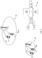
- FIG. 2-4 shows schematic block diagrams and a signalling diagram which illustrates a first exemplifying scenario for relaying an ongoing data session in a radio communications network 100.
- the first radio access node is the radio access node 110 and the second radio access node is the second wireless device 122, configured to operatively relay an ongoing data session for a first wireless device 121 as discussed above.
- the first gateway node is here a Packet Data Network Gateway, PGW 151, of the first wireless device 121 and the second gateway node is a PGW 152 of the second wireless device 122.
- a gateway node provides connectivity for the wireless terminals 121, 122 of the communications network 110 to one or more external Packet Data Networks (PDNs) e.g. the Internet or similar, and nodes or similar in the external network, e.g. such a the external network node 160 which will be discussed further below.
- PDNs Packet Data Networks
- the network gateway node may e.g. be a Gateway GPRS Support Node (GGSN) or a PGW as the PGW 151 mentioned above.
- GGSN Gateway GPRS Support Node
- PGW Packet Data Networks
- the first wireless device 121 is about to leave the radio coverage of the radio access node 110 and lose its connection with the radio communications network 100. This is illustrated to the left in Figure 2 by the double dashed arrow. As illustrated to the right in Figure 2 , in this example the first wireless device 121 has an ongoing data session A towards PGW 151 via the radio access network, RAN or E-UTRAN, in the radio communications network 100.
- the RAN or E-UTRAN comprises the radio access node 110 and possibly also the relaying wireless device 122
- the core network of the radio communications network 100 comprises such nodes as the ProSe function node 131, a MME 141 and the PGW 151 and/or the PGW 152s.
- the PGW 151 may transceive, i.e. receive and transmit, downlink, DL, and uplink, UL, data packets of the ongoing data session A between an external network node 160 and the first wireless device 121.
- the external network node 160 may e.g. be a Public Safety Application server or an internet server or similar.
- the data path of the ongoing data session A is illustrated to the right in Figure 3 by the dashed arrow.
- the PGW 151 may use a Packet Data Network, PDN, connection towards the first wireless device 121.
- PDN Packet Data Network
- the PGW 151 may communicate with the external network node 160 over a SGi interface.
- a MME serves a wireless device (e.g. such as the wireless device 121) to provide different functions, such as, Non-Access Stratum, NAS, signalling, EPS bearer management, roaming functions, etc.
- ProSe function node provides support for wireless devices to perform direct communication between each other, i.e. direct device-to-device, D2D, communication.
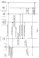
- signalling according to the signalling diagram depicted in Figure 3 may be performed.
- Figure 3 is a simplified, illustrated example of actions or operations which may be taken by the involved nodes and wireless devices in the scenario of Figure 2 .
- the first wireless device 121 has a data session A ongoing with the external network node 160 via the first PGW 151 and the radio access node 110 (not shown in Figure 3 ) in the radio communications network 100.
- the first wireless device 121 discovers radio connectivity towards the second wireless device 122 (e.g. via D2D functionality), which is capable of operating as a relay node for the ongoing data session A between the first wireless device 121 and the radio communications network 100.
- the second wireless device 122 e.g. via D2D functionality
- the first wireless device 121 determines that the ongoing data session is to be relayed via the second wireless device 122. For example, the determination may be based on that the first wireless device 121 detects that it is moving out of radio coverage of the radio access node 110, i.e. that it is about to lose its radio connection with the radio access node 110.
- the first wireless device 121 negotiates the relay service with the second wireless device 122, preferably over a D2D link for D2D communication.
- the second wireless device 122 may send an identifier to the first wireless device 121, which identifier indicates the identity of the second wireless device 122.
- the first wireless device 121 transmits a relay request message to a Proximity Service function, ProSe, node 131 in the radio communications network 100 wherein the first wireless device 121 is registered.
- ProSe Proximity Service function
- the relay request message comprises relay information indicating that the ongoing data session A is to be relayed via the second wireless device 122 with session continuity towards the first PGW 151 serving the first wireless device 121. It is preferred that the relay information comprises information indicating the identity of the first wireless device 121, for example indicating a ProSe User ID for the device 121 and/or the IP-address of the device 121 and/or some other identifier that is unique for the device 121 within the communication system 100. Additionally or alternatively, the relay information may indicate the identity of the second wireless device 122, for example, by comprising the identifier received from the second wireless device 122.
- the relay request message is preferably transmitted via the second wireless device 122 over the user plane (as indicated by the fully drawn arrow in Figure 2 ).
- the relay request message may instead be sent via the network node 110 and using the PDN Connection of the first wireless device 121 (as indicated by the dashed arrows in Figure 2 ).
- the ProSe function node 131 Upon receiving the relay request message, the ProSe function node 131 obtains, preferably based on the relay information or other information already available to the ProSE function node 131, mobility information indicating the MME 141 serving the first wireless device 121. For example, the ProSe function node 131 may use information indicating the identity of the first wireless device 121 (e.g. comprised by the relay information received in the relay request of action 303) to retrieve information indicating the MME 141 serving the first wireless device 121.
- the ProSe function node 131 transmits a first tunnel request message to the MME 141.
- the first tunnel request message comprises information, e.g. the received relay information, indicating that the ongoing data session A is to be relayed via the second wireless device 122.
- the ProSe function node 131 may send a message to the MME 141 serving the first wireless device 122 indicating that remote forwarding is needed via the second wireless device 122 for the ongoing data session A, e.g. an indicator indicating "Remote Forwarding Needed" may be used.
- the ProSe function node 121 may include this in the relay information to the MME 141. It should be noted that the IP address of the second wireless device 122 may also be stored in the MME 141. Alternatively, the IP address of the second wireless device 122 may be stored in the PGW 152 of the second wireless device 122.
- the MME 141 Upon receiving the first tunnel request message from the ProSe function node 131, the MME 141 obtains gateway information indicating a second PGW 152 serving the second wireless device 122, preferably using the information received in the tunnel request of action 305.
- the ProSe function node 131 is not serving the second wireless device 122, this may be performed by the MME 141 by, for example, signalling with another ProSe function node (not shown) serving the second wireless device 122. It should be noted that the second wireless device 122 should already have been in contact with and be registered in the other ProSe function node, or in the ProSe function node 131, in order for it to be authorized to act as a relay node. This may also be performed by the MME 141 by signalling with a Home Subscriber Server/Home Location Register, HSS/HLR.
- HSS/HLR Home Subscriber Server/Home Location Register
- the MME 141 transmits a second tunnel request message to the first PGW 151 (serving the first wireless device 121) indicating that it is to tunnel data packets of the ongoing data session A via the second PGW 152 (serving the second wireless device 122) based on the gateway information obtained in action 306.
- the MME 141 may thus indicate to the first PGW 151 to tunnel downlink data packets of the ongoing data session A of the first wireless device 121 towards the second wireless device 122 via the second PGW 152 serving the second wireless device 122.
- the MME 141 may also transmit a second tunnel request message to the PGW 152 indicating that it is to tunnel data packets of the ongoing data session A via the PGW 151.
- the MME 141 may indicate to the PGW 152 to tunnel uplink data packets of the ongoing data session A of the first wireless device 121 to the PGW 151. This may be referred to herein as reverse tunnelling.
- actions 308-311 are optional. However, in one or more or all of the actions 308, 309, 310 and 311 the PGW 151, the MME 141 the ProSe function node 131, and the second wireless device 122 respectively may acknowledge the receipt of their respectively received request messages.
- the PGW 151 sets up a tunnel 180 for the ongoing data session A such that the data packets of the ongoing data session A passes via the first PGW 151 and the second PGW 152.
- This enables downlink data packets of the ongoing data session A for the first wireless device 121 to be tunnelled from the PGW 151 to the second wireless device 122 through the existing Packet Data Network, PDN, connection between the second PGW 152 and the second wireless device 122. This can be performed while keeping the assigned IP address of the first wireless device 121 inside the tunnel 180.
- This may be performed using so-called IP-to-IP tunnelling, i.e. the PGW 151 tunnels the downlink data packets of the ongoing data session A of the first wireless device 121 directly to the second wireless device 122 routed via the PGW 152.
- the tunnel signalling of the tunnel 180 may, for example, be performed over a GPRS Tunnel Protocol, GTP, via a Serving Gateway, SGW (not shown).
- GTP GPRS Tunnel Protocol
- SGW Serving Gateway
- the PGW 151 and the second wireless device 122 may encapsulate the data packets in Generic Routing Encapsulation, GRE, IP data packets addressed to each other.
- GRE Generic Routing Encapsulation
- the PGW 151 may set up the tunnel 180 between the PGW 151 and the PGW 152, wherein the PGW 152 forwards the downlink data packets of the ongoing data session A of the first wireless device 121 to the second wireless device 122, which in turn forwards (relays) the downlink packets to the first wireless device 121.
- the first PGW 151 encapsulates the downlink packets in a new packet addressed to the second PGW 152.
- the second PGW 152 encapsulates the downlink packets received from the first PGW 151 in a new packet addressed to the second wireless device 122, though the second PGW 152 may remove the encapsulation made by the PGW 151 from the received packets before encapsulating them again.
- the second wireless device 122 removes the encapsulation made by the PGW 152 from the downlink packets received from the second PGW 152 and then forwards (relays) them to the first wireless device 121.
- This alternative may be advantageous when it is preferable to use separate bearers for the ongoing data session A of the first wireless device 121 being relayed and other data sessions of the second wireless device 122 in order to apply different Quality-of-Service requirements or different policy and charging functions, etc.
- the PGW 151 may transceive data packets of the ongoing data session A of the first wireless device 121 with the second wireless device 122 via the tunnel 180. This is shown by the dotted arrow 313 in Figure 3 .
- the second wireless device 122 upon receiving the encapsulated downlink tunnel data packets from the PGW 151 via the PGW 152 serving the second wireless device 122, decapsulates the received encapsulated downlink tunnel data packets to obtain downlink data packets of the ongoing data session A to the first wireless device 121. Then, the second wireless device 122 transmits the downlink data packets of the ongoing data session A to the first wireless device 121 using D2D communication over the D2D link.
- the second wireless device 122 may strip off (takes away) the previous encapsulation of the data packet, i.e. decapsulate the encapsulated data packets addressed to the second wireless device 122, and transmit the enclosed downlink data packet of the ongoing data session A addressed to the first wireless device 121 over the D2D link to the first wireless device 121.
- the first wireless device 121 may encapsulate uplink data packets of the ongoing data session A addressed to the PGW 151.
- the first wireless device 121 may then transmit the encapsulated uplink data packets over the D2D link to the second wireless device 121, which may forward it directly to the PGW 151 or the PGW 152 over the tunnel 180.
- This may be performed by the PGW 151 having a specific IP address to which the first wireless device 121 addresses the encapsulated data packets.
- the specific IP address of the PGW 151 may, for example, be notified to the first wireless device 121 when performing an attach procedure in the radio communications network 100, or during the tunnel setup procedure, e.g. via response messages.
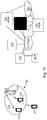
- Figure 4 illustrates the result of the signalling in Figure 3 . To the left, it is illustrated how the first wireless device 121 has left the radio coverage of the network node 110 and that the ongoing data session A, after the signalling in Figure 3 has been performed, is relayed via the second wireless device 122. The resulting data path of the ongoing data session A is illustrated to the right in Figure 4 .
- FIG. 5-7 shows schematic block diagrams and a signalling diagram which illustrate a second scenario for relaying an ongoing data session in a radio communications network 100.
- the first radio access node is the second wireless device 122 and the second radio access node is the radio access node 110.
- the first gateway node is the PGW 151 of the first wireless device and the second gateway node is the PGW 152 of the second wireless device.
- the first wireless device 121 is about to enter the radio coverage of the radio access node 110 when having an ongoing data session being relayed via the second wireless device 122.
- the entering is illustrated to the left in Figure 5 by the double dashed arrow.
- the first wireless device 121 has an ongoing data session A being relayed via the second wireless device 122 and tunnelled towards the PGW 151. This is illustrated to the right in Figure 5 by the dashed arrow.
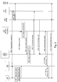
- signalling according to the signalling diagram depicted in Figure 6 may be performed.
- Figure 6 is a simplified, illustrated example of actions or operations which may be taken by the involved nodes and wireless devices in the scenario of Figure 5 .
- the first wireless device 121 has a data session A ongoing with the external network node 160 via the first PGW 151 and relayed via the second wireless device 122 and tunnelled via tunnel 180 towards the second PGW 152.
- the first wireless device 121 discovers that it is in coverage of the radio access node 110 and is able to establish a connection to the radio access node 110.
- the first wireless device 121 detects that it is moving into radio coverage of the network node 110 and establish a radio connection via the network node 110, for example, by performing an attach procedure according to 3GPP TS 23.401 V9.4.0.
- the first wireless device 121 transmits a relay request message to a Proximity Service function, ProSe, node 131 in the radio communications network 100 wherein the first wireless device 121 is registered.
- This action corresponds to Action 303 described above with reference to Figure 3 , except that in this case, the relay information indicate that the ongoing data session A is to be relayed via the radio access node 110 with session continuity towards the PGW 151.
- the relay request message may be transmitted via the second wireless device 122 (as indicated by the fully drawn arrows in Figure 6 ). Alternatively, if the connection to the network node 110 has already been established, the relay request message may be sent via the network node 110 (as indicated by the dashed arrow in Figure 6 ).
- the ProSe function node 131 Upon receiving the relay request message, the ProSe function node 131 obtains mobility information indicating a MME 141, serving the first wireless device 121. For example, the ProSe function node 131 may use the identity of the first wireless device 121 to retrieve information indicating the MME 141 serving the first wireless device 121. This action corresponds to Action 304 described above with reference to Figure 3 .
- the ProSe function node 131 may transmit a first tunnel request message to the MME 141.
- the first tunnel request message comprises information, e.g. the received relay information, indicating that the ongoing data session A is to be relayed via the radio access node 110.
- the ProSe function node 131 may send a message to the MME 141 serving the first wireless device 122 indicating that remote forwarding, i.e. relaying via the second wireless device122, is not needed any more for the ongoing data session A.
- the MME 141 Upon receiving the first tunnel request message from the ProSe function node 131, the MME 141 obtains gateway information indicating the PGW 152 serving the second wireless device 122, preferably using the information received in the tunnel request of action 605.
- the MME 141 transmits a second tunnel request message to the PGW 151 (serving the first wireless device 121) indicating that it is to stop tunneling data packets of the ongoing data session A via the PGW 152 according to the obtained gateway information.
- the MME 141 may thus indicate to the PGW 151 to stop tunnel downlink data packets of the ongoing data session A of the first wireless device 121 towards the second wireless device 122 via its PGW 152.
- the MME 141 may also transmit a second tunnel request message to the PGW 152 indicating that it is to stop tunnel data packets of the ongoing data session A via the PGW 151.
- the MME 141 may indicate to the PGW 152 to stop tunnel uplink data packets of the ongoing data session A of the first wireless device 121 to the PGW 151.
- the PGW 151, PGW 152, the MME 141, the ProSe function node 131, and the second wireless device 122 may each acknowledge the receipt of their respectively received request messages.
- the PGW 151 may proceed with the ongoing data session A directly with the first wireless device 121 over a conventional PDN connection. This is shown by the dotted arrow 612 in Figure 6 .
- Figure 7 illustrates the result of the signalling in Figure 6 . To the left it is illustrated how the first wireless device 121 has moved into the radio coverage of the network node 110 when having had an ongoing data session being relayed via the second wireless device 122. The resulting data path of the ongoing data session A is illustrated to the right in Figure 7 and is identical to the data path shown in Figure 2 .
- Figures 8-10 shows schematic block diagrams and a signalling diagram which illustrate a third scenario for relaying an ongoing data session in a radio communications network 100.
- the first radio access node is the second wireless device 122 and the second radio access node is a third wireless device 123.
- the first gateway node is the PGW 151
- the second gateway node is the PGW 152
- a third gateway node is PGW 153.
- the first wireless device 121 switches between having the ongoing data session being relayed via the second wireless device 122 to instead having the ongoing data session being relayed via a third wireless device 123.
- the first wireless device 121 may have an ongoing data session A being relayed via the second wireless device 122 and tunnelled between second wireless device 122 and the PGW 151.
- the data session A is illustrated to the right in Figure 8 by the dashed arrow.
- Figure 9 is a simplified, illustrated example of actions or operations which may be taken by the involved nodes and wireless devices in the scenario of Figure 8 .
- the first wireless device 121 has a data session A that is ongoing towards PGW 151 being relayed via the second wireless device 122 and tunnelled via tunnel 180 towards PGW 151. This is the same situation as the resulting relaying situation discussed above with reference to the right figure in Figure 5 .
- the first wireless device 121 discovers radio connectivity towards the third wireless device 123 (e.g. via D2D functionality), which is capable of operating as a relay node for the ongoing data session A between the first wireless device 121 and the radio communications network 100.
- the third wireless device 123 e.g. via D2D functionality
- the first wireless device 121 determines that the ongoing data session is to be relayed via the third wireless device 123. For example, the determination may be based on that the first wireless device 121 detects that it is about to lose its radio connection with the second wireless device 122.
- the first wireless device 121 negotiates a relay service with the third wireless device 122, preferably over a D2D link for D2D communication.
- the third wireless device 122 may send an identifier to the first wireless device 121, which identifier indicates the identity of the third wireless device 123.
- the first wireless device 121 transmits a relay request message to the Proximity Service function, ProSe, node 131 in the radio communications network 100 wherein the first wireless device 121 is registered.
- the relay request message comprises relay information indicating that the ongoing data session A is to be relayed via the third wireless device 123 with session continuity towards the PGW 151 serving the first wireless device 121. It is preferred that the relay information comprises information indicating the identity of the first wireless device 121, for example indicating a ProSe User ID for the device 121 and/or the IP-address of the device 121 and/or some other identifier that is unique for the device 121 within the communication system 100. Additionally or alternatively, the relay information may indicate the identity of the third wireless device 123, for example, by comprising the identifier received from the third wireless device 123.
- the relay request message is preferably transmitted via the third wireless device 123 over the user plane (as indicated by the fully drawn arrow in Figure 9 ). Alternatively, for example, if the connection via the second wireless device 122 has not yet been lost, the relay request message may instead be sent via the second wireless device 122 over the user plane (as indicated by the dashed arrows in Figure 9 ).
- the ProSe function node 131 Upon receiving the relay request message, the ProSe function node 131 obtains, preferably based on the relay information or other information already available to the ProSE function node 131, mobility information indicating the MME 141 serving the first wireless device 121. For example, the ProSe function node 131 may use information indicating the identity of the first wireless device 121 (e.g. comprised by the relay information received in the relay request of action 903) to retrieve information indicating the MME 141 serving the first wireless device 121.
- the ProSe function node 131 transmits a first tunnel request message to the MME 141.
- the first tunnel request message comprises information, e.g. the received relay information, indicating that the ongoing data session A is to be relayed via the third wireless device 123.
- the ProSe function node 131 may send a message to the MME 141 serving the first wireless device 121 indicating that remote forwarding is needed via the third wireless device 123 for the ongoing data session A, e.g. an indicator indicating "Remote Forwarding Needed" may be used.
- the ProSe function node 121 may include this in the relay information to the MME 141. It should be noted that the IP address of the third wireless device 123 may also be stored in the MME 141. Alternatively, the IP address of the third wireless device 123 may be stored in the PGW 153 of the third wireless device 123.
- the MME 141 Upon receiving the first tunnel request message from the ProSe function node 131, the MME 141 obtains gateway information indicating a PGW 153 serving the third wireless device 123, preferably using the information received in the tunnel request of action 905.
- the MME 141 transmits a second tunnel request message to the first PGW 151 (serving the first wireless device 121) indicating that it is to tunnel data packets of the ongoing data session A via the PGW 153 (serving the third wireless device 121) based on the gateway information obtained in action 306.
- the MME 141 may thus indicate to the PGW 151 to tunnel downlink data packets of the ongoing data session A of the first wireless device 121 towards the third wireless device 123 via PGW 153 serving the third wireless device 123.
- the MME 141 may also transmit a second tunnel request message to the PGW 153 indicating that it is to tunnel data packets of the ongoing data session A via the PGW 151.
- the MME 141 may indicate to the PGW 153 to tunnel uplink data packets of the ongoing data session A from the first wireless device 121 to the PGW 151. This may be referred to herein as reverse tunnelling.
- the PGW 151, PGW 153, the MME 141, the ProSe function node 131, and the third wireless device 123 may each acknowledge the receipt of their respectively received request messages.
- the PGW 151 sets up a tunnel 181 for the ongoing data session A such that the data packets of the ongoing data session A passes via the first PGW 151 and the PGW 153. This may be performed in the same or similar manner as described above for the second wireless device 122 in Action 312.
- the PGW 151 may transceive data packets of the ongoing data session A of the first wireless device 121 with the third wireless device 123 via the tunnel 181. This is shown by the dotted arrow 913 in Figure 9 , and may be performed by the third wireless device 123 and the PGW 153 in the same or similar manner as described above for the second wireless device 122 and the PGW 153 in Action 313.
- Figure 10 illustrates the result of the signalling in Figure 9 .To the left, it is illustrated how the first wireless device 121 has switched between having the ongoing data session A relayed via the second wireless device 122 to instead having the ongoing data session A relayed via a third wireless device 123.
- Example of embodiments of methods performed by a first wireless device 121 for relaying a data session via a second radio access node 122, 110, 123 in a radio communications network 100 wherein said data session is ongoing towards a first gateway node 151 via a first radio access node 110, 122, will now be described with reference to the flowchart depicted in Figure 11.
- Figure 11 is a simplified, illustrated example of actions or operations which may be taken by the wireless device 121.
- the first wireless device 121 discovers radio connectivity towards the second radio access node 122, 110, 123.
- This action is exemplified by the signalling in Actions 301, 601, 901 described with reference to Figures 2-10 .
- the first wireless device 121 determines that the ongoing data session is to be relayed via the second radio access node 122, 110, 123.
- This action is exemplified by the signalling in Actions 302, 602, 902 described with reference to Figures 2-10 .
- the first wireless device 121 then transmits a relay request message, to a proximity service function, ProSe, node 131 configured to operatively manage relaying of data sessions in the radio communications network 100, comprising relay information indicating that the ongoing data session is to be relayed via the second radio access node 122, 110, 123 with session continuity towards the first gateway node 151 serving the first wireless device 121.
- This action is exemplified by the signalling in Actions 303, 603, 903 described with reference to Figures 2-10 .
- the relay information further indicates that data packets of the ongoing data session is to be at least partly tunneled between the first gateway node 151 and the second radio access node 122, 110, 123. In some embodiments, the relay information further indicates the identity of the second radio access node 122, 110, 123.
- the first radio access node is a radio access node 110 serving a cell of the radio communication network 100. This is shown above by the examples of embodiments in Figures 2-4 .
- the second radio access node is a radio access node 110 serving a cell of the radio communication network 100. This is shown above by the examples of embodiments in Figures 5-7 .
- the first radio access node is a second wireless device 122, wherein said second wireless device 122 is capable of operating as a relay node of data transmissions between the first wireless device 121 and the radio communications network 100.
- the second radio access node is a third wireless device 123, wherein said third wireless device 123 is capable of operating as a relay node of data transmissions between the first wireless device 121 and the radio communications network 100. This is shown above by the examples of embodiments in Figures 8-10 .
- the first wireless device 121 may receive downlink data packets of the ongoing data session towards the first gateway node 151 via the first gateway node 151 and the second radio access node 122, 110, 123. Also, in some embodiments, the first wireless device 121 may transmit uplink data packets of the ongoing data session towards the first gateway node 151 via the second radio access node 122, 110, 123 by encapsulating the uplink data packets of the ongoing data session towards the first gateway node 151 in uplink tunnel data packets addressed to the first gateway node 151.
- the ProSe, function node 131 is generally configured to operatively manage relaying of data sessions in the radio communications network 100, e.g. manage relaying of an ongoing data session for the first wireless device 121 via the second wireless device 122.
- Figure 12 is a simplified, illustrated example of actions or operations which may be taken by the ProSe function node 131.
- the ProSe function node 131 receives relay request message, from the first wireless device 121, comprising relay information indicating that the ongoing data session is to be relayed via the second radio access node 122, 110, 123 with session continuity towards the first gateway node 151.
- This action is exemplified by the signalling in Actions 303, 603, 903 described with reference to Figures 2-10 .
- the ProSe function node 131 obtains mobility information indicating a Mobility Management Entity, MME 141, serving the first wireless device 121.
- MME 141 Mobility Management Entity
- This action is exemplified in Actions 304, 604, 904 described with reference to Figures 2-10 .
- the ProSe function node 131 transmits a first tunnel request message, to the MME 141, comprising the received relay information indicating that the ongoing data session is to be relayed via the second radio access node 122, 110, 123.
- This action is exemplified by the signalling in Actions 305, 605, 905 described with reference to Figures 2-10 .
- Example of embodiments of methods performed by a Mobility Management Entity, MME 141, for enabling relaying of a data session of a first wireless device 121 via a second radio access node 122, 110, 123 in a radio communications network 100, wherein said data session is ongoing towards a first gateway node 151 via a first radio access node 110, 122 in the radio communications network 100, will now be described with reference to the flowchart depicted in Figure 13.
- Figure 13 is a simplified, illustrated example of actions or operations which may be taken by the MME 141.
- the MME 141 receives a first tunnel request message, from a proximity service, ProSe, function node 131 configured to operatively manage relaying of data sessions in the radio communications network 100, comprising relay information indicating that the ongoing data session is to be relayed via the second radio access node 122, 110, 123.
- This action is exemplified by the signalling in Actions 305, 605, 905 described with reference to Figures 2-10 .
- the MME 141 obtains gateway information indicating a second gateway node 152, 153 serving the second radio access node 122, 110, 123 using the received relay information. This action is exemplified in Actions 306, 606, 906 described with reference to Figures 2-10 .
- the MME 141 transmits a second tunnel request message to the first gateway node 151 indicating that it is to tunnel data packets of the ongoing data session via the second gateway node 152, 153 according to the obtained gateway information.
- the MME 141 may indicate to the first gateway node to tunnel downlink data packets of an ongoing data session A of the first wireless device towards the second radio access node via the second gateway node 152 serving the second radio access node.
- This action is exemplified by the signalling in Actions 307, 607, 907 described with reference to Figures 2-10 .
- Example of embodiments of methods performed by a first gateway node 151 for enabling relaying of a data session of a first wireless device 121 via a second radio access node 122, 110, 123 in a radio communications network 100, wherein said data session is ongoing towards the first gateway node 151 via a first radio access node 110, 122 in the radio communications network 100, will now be described with reference to the flowchart depicted in Figure 14.
- Figure 14 is a simplified, illustrated example of actions or operations which may be taken by the first gateway node 151.
- the first gateway node 151 receives a second tunnel request message, from a MME 141, indicating that it is to tunnel data packets of the ongoing data session via a second gateway node 152, 153.
- This action is exemplified by the signalling in Actions 307, 607, 907 described with reference to Figures 2-10 .
- the first gateway node 151 sets up a tunnel 180, 181 via the second gateway node 152, 153 for the ongoing data session, such that the data packets of the ongoing data session passes via the first gateway node and the second gateway node.
- This action is exemplified by the signalling in Actions 312, 612, 912 described with reference to Figures 2-10 .
- The, the first gateway node 151 transceive, i.e. receive and/or transmit, data packets of the ongoing data session with the second radio access node 122, 110, 123 using the tunnel 180, 181.
- This action is exemplified by the signalling in Actions 313, 613, 913 described with reference to Figures 2-10 .
- the first gateway node 151 may transceive the data packets by transmitting downlink data packets of the ongoing data session to the first wireless device 121 by encapsulating the downlink data packets towards the first wireless device 121 in downlink tunnel data packets addressed to the second radio access node 122, 110, 123. In some embodiments, the first gateway node 151 may transceive the data packets by receiving uplink data packets of the ongoing data session from the first wireless device 121 by decapsulating uplink tunnel data packets addressed to the first gateway node 151.
- Example of embodiments of methods performed by a second wireless device 122 for relaying a data session between a first wireless device 121 and a first gateway node 151 in a radio communications network 100, said second wireless device 122, 123 being capable of operating as a relay node for the first wireless device (121) in the radio communications network 100 by using Device-to-Device, D2D, communication with the first wireless device 121, will now be described with reference to the flowchart depicted in Figure 15.
- Figure 15 is a simplified, illustrated example of actions or operations which may be taken by the second wireless device 122. This is also exemplified by the signalling in Actions 313, 613, 913 described with reference to Figures 2-10 .
- the second wireless device 122 receives encapsulated downlink tunnel data packets from the first gateway node 151 via a second gateway node 152, 153 serving the second wireless device 122, 123.
- the second wireless device 122 decapsulates the received encapsulated downlink tunnel data packets to obtain downlink data packets of the ongoing data session to the first wireless device 121.
- decapsulation means that the second wireless device 122 strips off (takes away) previous encapsulation of a data packet.
- The, the first gateway node 151 transmits the downlink data packets of the ongoing data session to the first wireless device 121, preferably using D2D communication.
- the first wireless device 121 may comprise the following arrangement depicted in Figure 16.
- Figure 16 shows a schematic block diagram of embodiments of the first wireless device 121.
- the first wireless device 121 may comprise a discovering module 1601, a determining module 1602, and a transceiving module 1603.
- the first wireless device 121 may comprise a processing circuitry 1610, which may also be referred to as processing module, processing unit or processor.
- the processing circuitry 1610 may comprise one or more of the discovering module 1601, determining module 1602 and transceiving module 1603, and/or perform the function thereof described below.
- the first wireless device 121 is configured to, e.g. by means of the discovering module 1601, discover radio connectivity towards the second radio access node 122, 110, 123. Also, the first wireless device 121 is configured to, e.g. by means of the determining module 1602, determine that the ongoing data session is to be relayed via the second radio access node 122, 110, 123. Further, the first wireless device 121 is configured to, e.g. by means of the transceiving 1603, transmit a relay request message, to a ProSe function node 131 configured to operatively manage relaying of data sessions in the radio communications network 100. The relay request message comprising relay information indicating that the ongoing data session is to be relayed via the second radio access node 122, 110, 123 with session continuity towards the first gateway node 151.
- the relay information further indicates that data packets of the ongoing data session is to be at least partly tunneled between the first gateway node 151 and the second radio access node 122, 110, 123. In some embodiments, the relay information further indicates the identity of the second radio access node 122, 110, 123.
- the first radio access node or the second radio access node is a network node 110 serving a cell in the radio communication network 100.
- the first radio access node and/or the second radio access node is a second or third wireless device 122, 123.
- the second and third wireless device 122, 123 are capable of operating as a relay node of data transmissions between the first wireless device 121 and the radio communications network 100.
- the first wireless device 121/the transceiving module 1603 may be configured to, receive downlink data packets of the ongoing data session towards the first gateway node 151 via the first gateway node 151 and the second radio access node 122, 110, 123. In some embodiments, the first wireless device 121/the transceiving module 1603 may be configured to, transmit comprising uplink data packets of the ongoing data session towards the first gateway node 151 via the second radio access node 122, 110, 123 by encapsulating the uplink data packets of the ongoing data session towards the first gateway node 151 in uplink tunnel data packets addressed to the first gateway node 151.
- the embodiments for relaying a data session via a second radio access node 122 in a radio communications network 100, wherein said data session is ongoing towards a first gateway node 151 via a first radio access node 110, 122 may be implemented through one or more processors, such as, e.g. the processing circuitry 1610 in the first wireless device 121 depicted in Figure 16 , together with computer program code for performing the functions and actions of the embodiments herein.
- the program code mentioned above may also be provided as a computer program product, for instance in the form of a data carrier carrying computer program code or code means for performing the embodiments herein when being loaded into the processing circuitry 1610 in the first wireless device 121.
- the computer program code may e.g.
- the carrier may be one of an electronic signal, optical signal, radio signal, or computer readable storage medium, such as, e.g. electronic memories like a RAM, a ROM, a Flash memory, a magnetic tape, a CD-ROM, a DVD, a Blueray disc, etc.
- the first wireless device 121 may further comprise a memory 1620, which may be referred to or comprise one or more memory modules or units.
- the memory 1620 may be arranged to be used to store executable instructions and data to perform the methods described herein when being executed in the first wireless device 121.
- the processing circuitry 1610 and the memory 1620 described above may refer to a combination of analog and digital circuits, and/or one or more processors configured with software and/or firmware, e.g. stored in the memory 1620, that when executed by the one or more processors such as the processing circuitry 1610 perform the method as described above.
- processors may be included in a single application-specific integrated circuit (ASIC), or several processors and various digital hardware may be distributed among several separate components, whether individually packaged or assembled into a system-on-a-chip (SoC).
- ASIC application-specific integrated circuit
- SoC system-on-a-chip
- some embodiments may comprise a computer program, comprising instructions which, when executed on at least one processor, e.g. the processing circuitry 1610 or modules 1601-1602, cause the at least one processor to carry out the method for relaying a data session via a second radio access node 122 in a radio communications network 100.
- some embodiments may, as described above, further comprise a carrier containing said computer program, wherein the carrier is one of an electronic signal, optical signal, radio signal, or computer readable storage medium.
- the proximity service, ProSe, function node 131 may comprise the following arrangement depicted in Figure 17 .
- the ProSe, function node 131 is configured to operatively manage relaying of data sessions in the radio communications network 100.
- Figure 17 shows a schematic block diagram of embodiments of the ProSe function node 131.
- the ProSe function node 131 may comprise a transceiving module 1701, and a obtaining module 1702.
- the ProSe function node 131 may comprise a processing circuitry 1710, which may also be referred to as processing module, processing unit or processor.
- the processing circuitry 1710 may comprise one or more of the transceiving module 1701 and the obtaining module 1702, and/or perform the function thereof described below.
- the ProSe function node 131 is configured to, e.g. by means of the transceiving module 1701, receive relay request message from the first wireless device 121 comprising relay information indicating that the ongoing data session is to be relayed via the second radio access node 122, 110, 123 with session continuity towards the first gateway node 151. Also, the ProSe function node 131 is configured to, e.g. by means of the obtaining module 1702, obtain mobility information indicating a MME 141 serving the first wireless device 121. Further, the ProSe function node 131 is configured to, e.g.
- the transceiving module 1701 transmits a first tunnel request message to a MME 141 serving the first wireless device 121 comprising the received relay information indicating that the ongoing data session is to be relayed via the second radio access node 122, 110, 123.
- the MME 141 may comprise the following arrangement depicted in Figure 18.
- Figure 18 shows a schematic block diagram of embodiments of the MME 141.
- the MME 141 may comprise a transceiving module 1801, and a obtaining module 1802.
- the network node 110 may comprise a processing circuitry 1810, which may also be referred to as processing module, processing unit or processor.
- the processing circuitry 1810 may comprise one or more of the transceiving module 1801 and the obtaining module 1802, and/or perform the function thereof described below.
- the MME 141 is configured to, e.g. by means of the transceiving module 1801, receive a first tunnel request message, from a proximity service, ProSe, function node 131 configured to operatively manage relaying of data sessions in the radio communications network 100, comprising relay information indicating that the ongoing data session is to be relayed via the second radio access node 122, 110,123. Also, the MME 141 is configured to, e.g. by means of the obtaining module 1802, obtain gateway information indicating a second gateway node 152, 153 serving the second radio access node 122, 110, 123 using the received relay information. Further, the MME 141 is configured to, e.g. by means of the transceiving module 1801, transmit a second tunnel request message to the first gateway node 151 indicating that it is to tunnel data packets of the ongoing data session via the second gateway node 152, 153.
- the first gateway node 151 may comprise the following arrangement depicted in Figure 19.
- Figure 19 shows a schematic block diagram of embodiments of the first gateway node 151.
- the first gateway node 151 may comprise a transceiving module 1901, and a setup module 1902.
- the first gateway node 151 may comprise a processing circuitry 1910, which may also be referred to as processing module, processing unit or processor.
- the processing circuitry 1910 may comprise one or more of the transceiving module 1901 and the determining module 1102, and/or perform the function thereof described below.
- the first gateway node 151 is configured to, e.g. by means of the transceiving module 1901, receive a second tunnel request message, from a MME 141, indicating that it is to tunnel data packets of the ongoing data session via a second gateway node 152, 153. Also, the first gateway node 151 is configured to, e.g. by means of the setup module 1902, set up a tunnel 180, 181 via the second gateway node 152, 153 for the ongoing data session. Further, the first gateway node 151 is configured to, e.g. by means of the transceiving module 1901, transceive data packets of the ongoing data session with the second radio access node 122, 110, 123 using the tunnel 180, 181.
- the first gateway node 151/transceiving module 1101 may be configured to, transceive the data packets of the ongoing data session by transmit downlink data packets of the ongoing data session to the first wireless device 121 by encapsulating the downlink data packets towards the first wireless device 121 in downlink tunnel data packets addressed to the second radio access node 122, 110, 123.
- the first gateway node 151/the transceiving module 1101 may be configured to, transceive the data packets of the ongoing data session by receive uplink data packets of the ongoing data session from the first wireless device 121 by decapsulating uplink tunnel data packets addressed to the first gateway node 151.
- the second wireless device 122, 123 being capable of operating as a relay node for the first wireless device 121 in the radio communications network 100 by using Device-to-Device, D2D, communication with the first wireless device 121, the second wireless device 122, 123 may comprise the following arrangement depicted in Figure 20.
- Figure 20 shows a schematic block diagram of embodiments of the second wireless device 122, 123.
- the second wireless device 122, 123 may comprise a transceiving module 2001, and a capsulating module 2002.
- the second wireless device 122, 123 may comprise a processing circuitry 2010, which may also be referred to as processing module, processing unit or processor.
- the processing circuitry 2010 may comprise one or more of the transceiving module 2001 and the capsulating module 2002, and/or perform the function thereof described below.
- the second wireless device 122, 123 is configured to, e.g. by means of the transceiving module 2001, receive encapsulated downlink tunnel data packets from the first gateway node 151 via a second gateway node 152, 153 serving the second wireless device 122, 123. Also, the second wireless device 122, 123 is configured to, e.g. by means of the capsulating module 2002, decapsulate the received encapsulated downlink tunnel data packets to obtain downlink data packets of the ongoing data session to the first wireless device 121. Further, the second wireless device 122, 123 is configured to, e.g. by means of the transceiving module 2001, transmit the downlink data packets of the ongoing data session to the first wireless device 121, preferably using D2D communication.
- the embodiments for relaying, or enabling relaying, of a data session of a first wireless device 121 via a second radio access node 122, 110, 123 described above may be implemented through one or more processors, such as, e.g. the processing circuitry 1710 in the ProSe function node 131 depicted in Figure 17 , the processing circuitry 1810 in the MME 141 depicted in Figure 18 , the processing circuitry 1910 in the first gateway node 151 depicted in Figure 19 , and the processing circuitry 2010 in the second wireless device 122 depicted in Figure 20 , together with computer program code for performing the functions and actions of the embodiments herein.
- processors such as, e.g. the processing circuitry 1710 in the ProSe function node 131 depicted in Figure 17 , the processing circuitry 1810 in the MME 141 depicted in Figure 18 , the processing circuitry 1910 in the first gateway node 151 depicted in Figure 19 , and the processing circuitry 2010 in the second wireless device
- the program codes mentioned above may also be provided as computer program products, for instance in the form of data carriers carrying computer program code or code means for performing the embodiments herein when being loaded into the respective processing circuitry in the respective nodes.
- the computer program codes may e.g. be provided as pure program code in the respective node or on a server and downloaded to the respective nodes.
- the carriers may be one of an electronic signal, optical signal, radio signal, or computer readable storage medium, such as, e.g. electronic memories like a RAM, a ROM, a Flash memory, a magnetic tape, a CD-ROM, a DVD, a Blueray disc, etc.
- Each of the respective nodes 131, 141, 151, 122 may further comprise a memory 1720, 1820, 1920, 2020, respectively, which may be referred to or comprise one or more memory modules or units.
- the memory 1720, 1820, 1920, 2020 may be arranged to be used to store executable instructions and data to perform the methods described herein when being executed in the respective node.
- the processing circuitries 1710, 1810, 1910, 2010 and their respective memory 1720, 1820, 1920, 2020 described above may refer to a combination of analog and digital circuits, and/or one or more processors configured with software and/or firmware, e.g.
- processors such as the corresponding processing circuitry 1710, 1810, 1910, 2010 perform the method as described in the embodiments above.
- processors may be included in a single application-specific integrated circuit ASIC, or several processors and various digital hardware may be distributed among several separate components, whether individually packaged or assembled into a system-on-a-chip (SoC).
- SoC system-on-a-chip
- some embodiments may comprise a computer program, comprising instructions which, when executed on at least one processor, e.g. the processing circuitry or module 1710, 1810, 1910, 2010, cause the at least one processor to carry out the method for relaying, or enabling relaying, of a data session of a first wireless device 121 via a second radio access node 122, 110, 123.
- some embodiments may, as described above, further comprise a carrier containing said computer program, wherein the carrier is one of an electronic signal, optical signal, radio signal, or computer readable storage medium.
- the common abbreviation "e.g.” which derives from the Latin phrase “exempli gratia,” may be used to introduce or specify a general example or examples of a previously mentioned item, and is not intended to be limiting of such item. If used herein, the common abbreviation “i.e.”, which derives from the Latin phrase “id est,” may be used to specify a particular item from a more general recitation.
- the common abbreviation “etc.”, which derives from the Latin expression “et cetera” meaning “and other things” or “and so on” may have been used herein to indicate that further features, similar to the ones that have just been enumerated, exist.
Landscapes
- Engineering & Computer Science (AREA)
- Computer Networks & Wireless Communication (AREA)
- Signal Processing (AREA)
- Mobile Radio Communication Systems (AREA)
Description
- Embodiments herein relate to relaying of ongoing data sessions. In particular, embodiments herein relate to relaying a data session of a first wireless device via a second radio access node, wherein the data session is ongoing via a first radio access node, in a radio communications network.
- In a typical radio communications network, wireless devices, also known as mobile stations, terminals and/or user equipments, UEs, communicate via a Radio Access Network, RAN, with one or more core networks. The radio access network covers a geographical area which may be divided into cell areas, with each cell area being served by a base station, e.g. a radio base station, RBS, or network node, which in some networks may also be called, for example, a "eNB", "NodeB" or "eNodeB". A cell may be a geographical area where radio coverage is provided by the radio base station at a base station site or an antenna site in case the antenna and the radio base station are not collocated. Each cell may be identified by an identity within the local radio area, which is broadcast in the cell. Another identity identifying the cell uniquely in the whole mobile network is also broadcasted in the cell. One base station may have one or more cells. A cell may be downlink and/or uplink cell. The base stations communicate over the air interface operating on radio frequencies with the user equipments within range of the base stations.
- A Universal Mobile Telecommunications System, UMTS, is a third generation mobile communication system, which evolved from the second generation, 2G, Global System for Mobile Communications, GSM. The UMTS terrestrial radio access network, UTRAN, is essentially a RAN using wideband code division multiple access, WCDMA, and/or High Speed Packet Access, HSPA, for user equipments. In a forum known as the Third Generation Partnership Project, 3GPP, telecommunications suppliers propose and agree upon standards for third generation networks and UTRAN specifically, and investigate enhanced data rate and radio capacity. In some versions of the RAN as e.g. in UMTS, several base stations may be connected, e.g., by landlines or microwave, to a controller node, such as a radio network controller, RNC, or a base station controller, BSC, which supervises and coordinates various activities of the plural base stations connected thereto. The RNCs are typically connected to one or more core networks.
- Specifications for the Evolved Packet System, EPS, have been completed within the 3rd Generation Partnership Project, 3GPP, and this work continues in the coming 3GPP releases. The EPS comprises the Evolved Universal Terrestrial Radio Access Network, E-UTRAN, also known as the Long Term Evolution, LTE, radio access, and the Evolved Packet Core, EPC, also known as System Architecture Evolution, SAE, core network. E-UTRAN/LTE is a variant of a 3GPP radio access technology wherein the radio base station nodes are directly connected to the EPC core network rather than to RNCs. In general, in E-UTRAN/LTE the functions of a RNC are distributed between the radio base stations nodes, e.g. eNodeBs in LTE, and the core network. As such, the Radio Access Network, RAN, of an EPS has an essentially flat rather than hierarchical architecture comprising radio base station nodes without reporting to RNCs.
- In 3GPP LTE Release 12, a functionality called Proximity Services, ProSe, also referred to herein as a proximity service function, is specified. This functionality provides support for wireless devices to perform direct communication between each other, i.e. direct device-to-device, D2D, communication, by using a radio channel based on LTE technology. According to one example, for Public Safety, PS, users, it is allowed for two wireless devices to communicate directly between each other when there is no radio coverage from radio communications network, i.e. when there is no radio base station within reach.
- Furthermore, when a first wireless device of a PS user is within radio coverage of a radio base station, e.g. eNB or eNodeB, and a second wireless device of another PS user is out of radio coverage from a radio base station, the first wireless device may act as a relay station between the out-of-coverage, second wireless device and the radio base station. In this way the out-of-coverage, second wireless device of the other PS user will be able to communicate with the radio communications network without being connected to or have access to a radio base station. This relay functionality is also specified in 3GPP LTE Release 12, wherein it describes a relay situation or scenario where a new data session is created for the second wireless device via the first wireless device. It should be emphasised that the relay functionality, where a first wireless device may act as a relay station between the out-of-coverage, second wireless device and the radio base station, is generally applicable in other situations, e.g. in situations that are similar to the exemplifying Public Safety (PS) situation mentioned above.
- However, as the first and second wireless device often are mobile and may move into and out of radio coverage, there is a need to be able to maintain ongoing data sessions via the relay devices and radio base stations without having to create new data connections each time there is a change in radio coverage or relay possibilities.
- An example of prior art technology can be found in the published patent application
US 2014/0114162 A1 . The application discloses a method, an apparatus, and a computer program product for wireless communication. The apparatus receives discovery resource information from a base station, sends a discovery signal based on the discovery resource information, and receives from at least one user equipment (UE) a request for relaying with the base station based on the discovery signal. The apparatus may also receive a discovery signal from a relay, and send to the relay a request for relaying with a base station based on the discovery signal. The apparatus may further receive a discovery signal from each of a plurality of relays, determine to select one of the plurality of relays based on the discovery signal from each relay, and send to a selected relay a request for relaying with a base station based on the discovery signal when one of the plurality of relays is determined to be selected. - It is an object of embodiments herein to provide session continuity when relaying an ongoing data session.
- According to a first aspect of embodiments herein, the object is achieved by a method performed by a first wireless device for relaying a data session via a second radio access node in a radio communications network. The data session is ongoing towards a first gateway node via a first radio access node in the radio communications network. The first wireless device discovers radio connectivity towards the second radio access node. The first wireless device also determines that the ongoing data session is to be relayed via the second radio access node. Then, the first wireless device transmits a relay request message, to a proximity service function, ProSe, node configured to operatively manage relaying of data sessions in the radio communications network, comprising relay information indicating that the ongoing data session is to be relayed via the second radio access node with session continuity towards the first gateway node.
- Keeping session continuity towards the first gateway node serving the first wireless device at relaying via a second wireless device makes it possible for external network nodes to maintain the IP-address unchanged towards the first gateway when communicating with the first wireless device. Thus, an external network node communicating with the first wireless device does not have to change the IP-address to the address of the gateway serving the relaying second wireless device.
- In addition, keeping session continuity makes it possible to keep a possible Policy and Charging Enforcement Function (PCEF) or similar executed by the first gateway with respect to the ongoing data session. Thus, a possible PCEF or similar does not have to be terminated and/or moved another gateway serving the relaying second wireless device.
- According to a second aspect of embodiments herein, the object is achieved by a first wireless device for relaying a data session via a second radio access node in a radio communications network. The data session is ongoing towards a first gateway node via a first radio access node in the radio communications network. The first wireless device is configured to discover radio connectivity towards the second radio access node, determine that the ongoing data session is to be relayed via the second radio access node, and transmit a relay request message, to a ProSe function node configured to operatively manage relaying of data sessions in the radio communications network, comprising relay information indicating that the ongoing data session is to be relayed via the second radio access node with session continuity towards the first gateway node.
- According to a third aspect of embodiments herein, the object is achieved by a method performed by a ProSe function node for enabling relaying of a data session of a first wireless device via a second radio access node in the radio communications network. The data session is ongoing towards a first gateway node via a first radio access node in a radio communications network. The ProSe function node is configured to operatively manage relaying of data sessions in the radio communications network. The ProSe function node receives a relay request message, from the first wireless device, comprising relay information indicating that the ongoing data session is to be relayed via the second radio access node with session continuity towards the first gateway node. Then, the ProSe function node obtains mobility information indicating a MME serving the first wireless device. Also, the ProSe function node transmits a first tunnel request message to the MME comprising the received relay information indicating that the ongoing data session is to be relayed via the second radio access node.
- According to a fourth aspect of embodiments herein, the object is achieved by a ProSe function node for enabling relaying of a data session of a first wireless device via a second radio access node in the radio communications network. The data session is ongoing towards a first gateway node via a first radio access node in a radio communications network. The ProSe function node is configured to operatively manage relaying of data sessions in the radio communications network. The ProSe function node is further configured to receive relay request message, from the first wireless device, comprising relay information indicating that the ongoing data session is to be relayed via the second radio access node with session continuity towards the first gateway node, obtain mobility information indicating a MME serving the first wireless device, and transmit a first tunnel request message to the MME comprising the received relay information indicating that the ongoing data session is to be relayed via the second radio access node.
- By having a first wireless device transmitting a relay request message for an ongoing data session, when it has determined that an ongoing data session via a first access node should be relayed via a second radio access node instead, to a ProSe function node. The ProSe function node is then able to perform signalling with the MME serving the first wireless device such that the MME may instruct the gateway node of the first wireless device to set up a tunnel towards the second radio access node or the gateway node of the second radio access node. The gateway node of the first wireless device and the second radio access node, or its gateway node, may then use the tunnel to transceive data packets of the ongoing data session on behalf of the first wireless device.
- In this way, the first wireless device is able to keep its configurations, such as, e.g. IP address, determined by the first radio access node, i.e. its original gateway node with which the first wireless device first established the data session; this, while the second access node may use its existing data connection towards its gateway node to transmit and receive data packets on behalf of the first wireless device. Thus, no new data connections are required to maintain the ongoing data session when switching to relaying via the second radio access node instead of the first radio access node.
- Hence, session continuity is provided when relaying ongoing data sessions.
- Embodiments will now be described in more detail in relation to the enclosed drawings.
- Figure 1
- is a schematic block diagram illustrating embodiments of wireless devices in a radio communications network,
- Figure 2
- illustrates a first scenario for relaying an ongoing data session in a radio communications network,
- Figure 3
- is a signalling diagram for relaying an ongoing data session in the first scenario of
Figure 2 according to embodiments of a first and second wireless device, a ProSe function node, an MME and gateway nodes in a radio communications network, - Figure 4
- is a schematic block diagram illustrating the result of the signalling in
Figure 3 , - Figure 5
- illustrates a second scenario for relaying an ongoing data session in a radio communications network,
- Figure 6
- is a signalling diagram for relaying an ongoing data session in the second scenario of
Figure 5 according to embodiments of a first and second wireless device, a ProSe function node, an MME and gateway nodes in a radio communications network, - Figure 7
- is a schematic block diagram illustrating the result of the signalling in
Figure 6 , - Figure 8
- illustrates a third scenario for relaying an ongoing data session in a radio communications network,
- Figure 9
- is a signalling diagram for relaying an ongoing data session in the third scenario of
Figure 8 according to embodiments of a first and second wireless device, a ProSe function node, an MME and gateway nodes in a radio communications network, - Figure 10
- is a schematic block diagram illustrating the result of the signalling in
Figure 9 , - Figure 11
- is a flowchart depicting embodiments of a method in a first wireless device,
- Figure 12
- is a flowchart depicting embodiments of a method in a ProSe function node,
- Figure 13
- is a flowchart depicting embodiments of a method in a MME,
- Figure 14
- is a flowchart depicting embodiments of a method in a gateway node.
- Figure 15
- is a flowchart depicting embodiments of a method in a second wireless device,
- Figure 16
- is a schematic block diagram depicting embodiments of a first wireless device,
- Figure 17
- is a schematic block diagram depicting embodiments of a ProSe function node,
- Figure 18
- is a schematic block diagram depicting embodiments of an MME,
- Figure 19
- is a schematic block diagram depicting embodiments of a gateway node.
- Figure 20
- is a schematic block diagram depicting embodiments of a second wireless device,
- The figures are schematic and simplified for clarity, and they merely show details which are essential to the understanding of the embodiments presented herein, while other details have been left out. Throughout, the same reference numerals are used for identical or corresponding parts or steps.
-
Figure 1 shows an example of aradio communication network 100 in which embodiments herein may be implemented. Although illustrated in the example ofFigure 1 as an LTE network, theradio communications network 100 should not be considered limited to this specific wireless communications technology. - The
radio communications system 100 comprises aradio access node 110. Theradio access node 110 may e.g. be an eNodeB (eNB), or a Home Node B, a Home eNode B, femto Base Station (BS), pico BS or any other network unit capable to serve wireless devices in theradio communications network 100. Theradio access node 110 may also be e.g. a base station controller, a network controller, a relay node, a repeater, an access point, a radio access point, a Remote Radio Unit (RRU) or a Remote Radio Head (RRH). - The
radio access node 110 is configured to be connected to and form part of an Enhanced - Universal Terrestrial Radio Access Network, E-UTRAN, of theradio communications network 100. - In the example shown in
Figure 1 , theradio access node 110 is configured to provide wireless radio coverage to wireless devices in acell 115. A cell may be seen as a geographical area where radio coverage is provided by radio base station equipment at a base station site or at remote locations in Remote Radio Units (RRU). The cell definition may also incorporate frequency bands and radio access technology used for transmissions, which means that two different cells may cover the same geographical area but using different frequency bands. Each cell may be identified by an identity within the local radio area, which is broadcast in the cell. Another identity identifying each cell uniquely in the wholeradio communication network 100 may also be broadcasted in the cell. Theradio access node 110 communicates over the air or radio interface operating on radio frequencies with wireless devices within range of theradio access node 110. - Furthermore, in the example of
Figure 1 , a first andsecond wireless device cell 115. The first andsecond wireless device radio communications network 100. The first andsecond wireless device - The first and
second wireless device radio communications network 100 via theradio access node 110 over a radio link, shown by fully drawn arrows, when present in thecell 115 served by theradio access node 110. - Furthermore, it is preferred that the first and
second wireless device second wireless device second wireless device radio communications network 100. The radio resource in the cellular spectrum in thecell 115 used by the D2D communication may at least partly overlap with the radio resources used by the cellular communications of other wireless devices in thecell 115. - Although embodiments below are described with reference to the example of
Figure 1 , this example should not be construed as limiting to the embodiments herein, but merely as an example made for illustrative purposes. - An issue which is resolved by the embodiments described below is how to provide session continuity when relaying an ongoing data session for the
first wireless device 121, such that that the ongoing data session is relayed via thesecond wireless device 122 or any other radio access node with session continuity towards the gateway node serving the first wireless device. - This is done by having the first wireless device transmitting a relay request to a ProSe function node (e.g.
ProSe function node 131 to be discussed further below with reference toFigure 3 ) for the ongoing data session. The request is preferably transmitted when the first wireless device has determined that the data session ongoing via a first access node should be relayed via a second radio access node. The ProSe function node is generally configured to operatively manage relaying of data sessions in the radio communications network, e.g. manage relaying of an ongoing data session for a first wireless device via a second wireless device. The ProSe function node is configured to operatively perform signalling with a Mobility Management Entity (MME) serving the first wireless device causing the MME to instruct the gateway node of the first wireless device to set up a tunnel towards the second radio access node or the gateway node of the second radio access node. The gateway node of the first wireless device and the second radio access node can then use the tunnel to transceive data packets of the ongoing data session on behalf of the first wireless device. -
Figures 2-4 shows schematic block diagrams and a signalling diagram which illustrates a first exemplifying scenario for relaying an ongoing data session in aradio communications network 100. In this first scenario, the first radio access node is theradio access node 110 and the second radio access node is thesecond wireless device 122, configured to operatively relay an ongoing data session for afirst wireless device 121 as discussed above. Also, the first gateway node is here a Packet Data Network Gateway,PGW 151, of thefirst wireless device 121 and the second gateway node is aPGW 152 of thesecond wireless device 122. - Before proceeding it should be explained that a gateway node provides connectivity for the
wireless terminals communications network 110 to one or more external Packet Data Networks (PDNs) e.g. the Internet or similar, and nodes or similar in the external network, e.g. such a theexternal network node 160 which will be discussed further below. The network gateway node may e.g. be a Gateway GPRS Support Node (GGSN) or a PGW as thePGW 151 mentioned above. - In
Figure 2 , thefirst wireless device 121 is about to leave the radio coverage of theradio access node 110 and lose its connection with theradio communications network 100. This is illustrated to the left inFigure 2 by the double dashed arrow. As illustrated to the right inFigure 2 , in this example thefirst wireless device 121 has an ongoing data session A towardsPGW 151 via the radio access network, RAN or E-UTRAN, in theradio communications network 100. - With reference to
Figure 3 and partly toFigure 2 , the RAN or E-UTRAN comprises theradio access node 110 and possibly also the relayingwireless device 122 , while the core network of theradio communications network 100 comprises such nodes as theProSe function node 131, aMME 141 and thePGW 151 and/or the PGW 152s. ThePGW 151 may transceive, i.e. receive and transmit, downlink, DL, and uplink, UL, data packets of the ongoing data session A between anexternal network node 160 and thefirst wireless device 121. Theexternal network node 160 may e.g. be a Public Safety Application server or an internet server or similar. The data path of the ongoing data session A is illustrated to the right inFigure 3 by the dashed arrow. ThePGW 151 may use a Packet Data Network, PDN, connection towards the first wireless device 121.ThePGW 151 may communicate with theexternal network node 160 over a SGi interface. - Before proceeding it should be explained that a MME (e.g. such as MME 141) serves a wireless device (e.g. such as the wireless device 121) to provide different functions, such as, Non-Access Stratum, NAS, signalling, EPS bearer management, roaming functions, etc.
- Also, in addition to what has already been said above about the Proximity Service function, ProSe, node it should be clarified that the ProSe function node provides support for wireless devices to perform direct communication between each other, i.e. direct device-to-device, D2D, communication.
- Now, in order to provide session continuity for the ongoing data session A according to this first scenario, i.e. when leaving the radio coverage of the
radio access node 110, signalling according to the signalling diagram depicted inFigure 3 may be performed. -
Figure 3 is a simplified, illustrated example of actions or operations which may be taken by the involved nodes and wireless devices in the scenario ofFigure 2 . - The
first wireless device 121 has a data session A ongoing with theexternal network node 160 via thefirst PGW 151 and the radio access node 110 (not shown inFigure 3 ) in theradio communications network 100. - The
first wireless device 121 discovers radio connectivity towards the second wireless device 122 (e.g. via D2D functionality), which is capable of operating as a relay node for the ongoing data session A between thefirst wireless device 121 and theradio communications network 100. - In this action, the
first wireless device 121 determines that the ongoing data session is to be relayed via thesecond wireless device 122. For example, the determination may be based on that thefirst wireless device 121 detects that it is moving out of radio coverage of theradio access node 110, i.e. that it is about to lose its radio connection with theradio access node 110. Thefirst wireless device 121 negotiates the relay service with thesecond wireless device 122, preferably over a D2D link for D2D communication. In this connection, thesecond wireless device 122 may send an identifier to thefirst wireless device 121, which identifier indicates the identity of thesecond wireless device 122. - In this action, the
first wireless device 121 transmits a relay request message to a Proximity Service function, ProSe,node 131 in theradio communications network 100 wherein thefirst wireless device 121 is registered. - The relay request message comprises relay information indicating that the ongoing data session A is to be relayed via the
second wireless device 122 with session continuity towards thefirst PGW 151 serving thefirst wireless device 121. It is preferred that the relay information comprises information indicating the identity of thefirst wireless device 121, for example indicating a ProSe User ID for thedevice 121 and/or the IP-address of thedevice 121 and/or some other identifier that is unique for thedevice 121 within thecommunication system 100. Additionally or alternatively, the relay information may indicate the identity of thesecond wireless device 122, for example, by comprising the identifier received from thesecond wireless device 122. - The relay request message is preferably transmitted via the
second wireless device 122 over the user plane (as indicated by the fully drawn arrow inFigure 2 ). Alternatively, for example, if the connection to thenetwork node 110 has not yet been lost, the relay request message may instead be sent via thenetwork node 110 and using the PDN Connection of the first wireless device 121 (as indicated by the dashed arrows inFigure 2 ). - Upon receiving the relay request message, the
ProSe function node 131 obtains, preferably based on the relay information or other information already available to theProSE function node 131, mobility information indicating theMME 141 serving thefirst wireless device 121. For example, theProSe function node 131 may use information indicating the identity of the first wireless device 121 (e.g. comprised by the relay information received in the relay request of action 303) to retrieve information indicating theMME 141 serving thefirst wireless device 121. - In this action, the
ProSe function node 131 transmits a first tunnel request message to theMME 141. The first tunnel request message comprises information, e.g. the received relay information, indicating that the ongoing data session A is to be relayed via thesecond wireless device 122. Thus, theProSe function node 131 may send a message to theMME 141 serving thefirst wireless device 122 indicating that remote forwarding is needed via thesecond wireless device 122 for the ongoing data session A, e.g. an indicator indicating "Remote Forwarding Needed" may be used. - If the IP address of the
second wireless device 122 is available to theProSe function 131, e.g. in the relay information received inaction 303 or in the mobility information obtained inaction 304, then theProSe function node 121 may include this in the relay information to theMME 141. It should be noted that the IP address of thesecond wireless device 122 may also be stored in theMME 141. Alternatively, the IP address of thesecond wireless device 122 may be stored in thePGW 152 of thesecond wireless device 122. - Upon receiving the first tunnel request message from the
ProSe function node 131, theMME 141 obtains gateway information indicating asecond PGW 152 serving thesecond wireless device 122, preferably using the information received in the tunnel request ofaction 305. - If the
ProSe function node 131 is not serving thesecond wireless device 122, this may be performed by theMME 141 by, for example, signalling with another ProSe function node (not shown) serving thesecond wireless device 122. It should be noted that thesecond wireless device 122 should already have been in contact with and be registered in the other ProSe function node, or in theProSe function node 131, in order for it to be authorized to act as a relay node. This may also be performed by theMME 141 by signalling with a Home Subscriber Server/Home Location Register, HSS/HLR. - In this action, the
MME 141 transmits a second tunnel request message to the first PGW 151 (serving the first wireless device 121) indicating that it is to tunnel data packets of the ongoing data session A via the second PGW 152 (serving the second wireless device 122) based on the gateway information obtained inaction 306. TheMME 141 may thus indicate to thefirst PGW 151 to tunnel downlink data packets of the ongoing data session A of thefirst wireless device 121 towards thesecond wireless device 122 via thesecond PGW 152 serving thesecond wireless device 122. - Optionally, the
MME 141 may also transmit a second tunnel request message to thePGW 152 indicating that it is to tunnel data packets of the ongoing data session A via thePGW 151. Thus, theMME 141 may indicate to thePGW 152 to tunnel uplink data packets of the ongoing data session A of thefirst wireless device 121 to thePGW 151. This may be referred to herein as reverse tunnelling. - In the actions 308-311 are optional. However, in one or more or all of the
actions PGW 151, theMME 141 theProSe function node 131, and thesecond wireless device 122 respectively may acknowledge the receipt of their respectively received request messages. - Here, after receiving the second tunnel request message from the
MME 141 indicating that it is to tunnel data packets of the ongoing data session A via a second gateway node, thePGW 151 sets up atunnel 180 for the ongoing data session A such that the data packets of the ongoing data session A passes via thefirst PGW 151 and thesecond PGW 152. This enables downlink data packets of the ongoing data session A for thefirst wireless device 121 to be tunnelled from thePGW 151 to thesecond wireless device 122 through the existing Packet Data Network, PDN, connection between thesecond PGW 152 and thesecond wireless device 122. This can be performed while keeping the assigned IP address of thefirst wireless device 121 inside thetunnel 180. - This may be performed using so-called IP-to-IP tunnelling, i.e. the
PGW 151 tunnels the downlink data packets of the ongoing data session A of thefirst wireless device 121 directly to thesecond wireless device 122 routed via thePGW 152. The tunnel signalling of thetunnel 180 may, for example, be performed over a GPRS Tunnel Protocol, GTP, via a Serving Gateway, SGW (not shown). Here, thePGW 151 and thesecond wireless device 122 may encapsulate the data packets in Generic Routing Encapsulation, GRE, IP data packets addressed to each other. - Alternatively, the
PGW 151 may set up thetunnel 180 between thePGW 151 and thePGW 152, wherein thePGW 152 forwards the downlink data packets of the ongoing data session A of thefirst wireless device 121 to thesecond wireless device 122, which in turn forwards (relays) the downlink packets to thefirst wireless device 121. Here, it is preferred that thefirst PGW 151 encapsulates the downlink packets in a new packet addressed to thesecond PGW 152. Similarly, it is preferred that thesecond PGW 152 encapsulates the downlink packets received from thefirst PGW 151 in a new packet addressed to thesecond wireless device 122, though thesecond PGW 152 may remove the encapsulation made by thePGW 151 from the received packets before encapsulating them again. Similarly, it is preferred that thesecond wireless device 122 removes the encapsulation made by thePGW 152 from the downlink packets received from thesecond PGW 152 and then forwards (relays) them to thefirst wireless device 121. This alternative may be advantageous when it is preferable to use separate bearers for the ongoing data session A of thefirst wireless device 121 being relayed and other data sessions of thesecond wireless device 122 in order to apply different Quality-of-Service requirements or different policy and charging functions, etc. - Since there is a limit to the number of PDN connections that may be set up between a wireless device and a PGW, this advantageously requires no new PDN connection to be set up between the
second wireless device 122 and thePGW 151 in order to maintain the ongoing data session A when relaying it via thesecond wireless device 122. - After the setup in
Action 312, thePGW 151 may transceive data packets of the ongoing data session A of thefirst wireless device 121 with thesecond wireless device 122 via thetunnel 180. This is shown by the dottedarrow 313 inFigure 3 . - As already indicated above, upon receiving the encapsulated downlink tunnel data packets from the
PGW 151 via thePGW 152 serving thesecond wireless device 122, thesecond wireless device 122 decapsulates the received encapsulated downlink tunnel data packets to obtain downlink data packets of the ongoing data session A to thefirst wireless device 121. Then, thesecond wireless device 122 transmits the downlink data packets of the ongoing data session A to thefirst wireless device 121 using D2D communication over the D2D link. - In other words, the
second wireless device 122 may strip off (takes away) the previous encapsulation of the data packet, i.e. decapsulate the encapsulated data packets addressed to thesecond wireless device 122, and transmit the enclosed downlink data packet of the ongoing data session A addressed to thefirst wireless device 121 over the D2D link to thefirst wireless device 121. - It should also be noted that, for uplink data packets, the
first wireless device 121 may encapsulate uplink data packets of the ongoing data session A addressed to thePGW 151. Thefirst wireless device 121 may then transmit the encapsulated uplink data packets over the D2D link to thesecond wireless device 121, which may forward it directly to thePGW 151 or thePGW 152 over thetunnel 180. This may be performed by thePGW 151 having a specific IP address to which thefirst wireless device 121 addresses the encapsulated data packets. The specific IP address of thePGW 151 may, for example, be notified to thefirst wireless device 121 when performing an attach procedure in theradio communications network 100, or during the tunnel setup procedure, e.g. via response messages. -
Figure 4 illustrates the result of the signalling inFigure 3 . To the left, it is illustrated how thefirst wireless device 121 has left the radio coverage of thenetwork node 110 and that the ongoing data session A, after the signalling inFigure 3 has been performed, is relayed via thesecond wireless device 122. The resulting data path of the ongoing data session A is illustrated to the right inFigure 4 . -
Figures 5-7 shows schematic block diagrams and a signalling diagram which illustrate a second scenario for relaying an ongoing data session in aradio communications network 100. In this second scenario, the first radio access node is thesecond wireless device 122 and the second radio access node is theradio access node 110. Also, the first gateway node is thePGW 151 of the first wireless device and the second gateway node is thePGW 152 of the second wireless device. - In
Figure 5 , thefirst wireless device 121 is about to enter the radio coverage of theradio access node 110 when having an ongoing data session being relayed via thesecond wireless device 122. The entering is illustrated to the left inFigure 5 by the double dashed arrow. Here, due to the signalling described with reference toFigure 3 above, thefirst wireless device 121 has an ongoing data session A being relayed via thesecond wireless device 122 and tunnelled towards thePGW 151. This is illustrated to the right inFigure 5 by the dashed arrow. - In order to provide session continuity for the ongoing data session A according to this scenario, i.e. when entering the radio coverage of the
radio access node 110, signalling according to the signalling diagram depicted inFigure 6 may be performed. -
Figure 6 is a simplified, illustrated example of actions or operations which may be taken by the involved nodes and wireless devices in the scenario ofFigure 5 . - The
first wireless device 121 has a data session A ongoing with theexternal network node 160 via thefirst PGW 151 and relayed via thesecond wireless device 122 and tunnelled viatunnel 180 towards thesecond PGW 152. - The
first wireless device 121 discovers that it is in coverage of theradio access node 110 and is able to establish a connection to theradio access node 110. - The
first wireless device 121 detects that it is moving into radio coverage of thenetwork node 110 and establish a radio connection via thenetwork node 110, for example, by performing an attach procedure according to 3GPP TS 23.401 V9.4.0. - In this action, the
first wireless device 121 transmits a relay request message to a Proximity Service function, ProSe,node 131 in theradio communications network 100 wherein thefirst wireless device 121 is registered. This action corresponds toAction 303 described above with reference toFigure 3 , except that in this case, the relay information indicate that the ongoing data session A is to be relayed via theradio access node 110 with session continuity towards the PGW 151.The relay request message may be transmitted via the second wireless device 122 (as indicated by the fully drawn arrows inFigure 6 ). Alternatively, if the connection to thenetwork node 110 has already been established, the relay request message may be sent via the network node 110 (as indicated by the dashed arrow inFigure 6 ). - Upon receiving the relay request message, the
ProSe function node 131 obtains mobility information indicating aMME 141, serving thefirst wireless device 121. For example, theProSe function node 131 may use the identity of thefirst wireless device 121 to retrieve information indicating theMME 141 serving thefirst wireless device 121. This action corresponds toAction 304 described above with reference toFigure 3 . - In this action, the
ProSe function node 131 may transmit a first tunnel request message to theMME 141. The first tunnel request message comprises information, e.g. the received relay information, indicating that the ongoing data session A is to be relayed via theradio access node 110. This means that theProSe function node 131 may send a message to theMME 141 serving thefirst wireless device 122 indicating that remote forwarding, i.e. relaying via the second wireless device122, is not needed any more for the ongoing data session A. - Upon receiving the first tunnel request message from the
ProSe function node 131, theMME 141 obtains gateway information indicating thePGW 152 serving thesecond wireless device 122, preferably using the information received in the tunnel request ofaction 605. - In this action, the
MME 141 transmits a second tunnel request message to the PGW 151 (serving the first wireless device 121) indicating that it is to stop tunneling data packets of the ongoing data session A via thePGW 152 according to the obtained gateway information. TheMME 141 may thus indicate to thePGW 151 to stop tunnel downlink data packets of the ongoing data session A of thefirst wireless device 121 towards thesecond wireless device 122 via itsPGW 152. Optionally, theMME 141 may also transmit a second tunnel request message to thePGW 152 indicating that it is to stop tunnel data packets of the ongoing data session A via thePGW 151. Thus, theMME 141 may indicate to thePGW 152 to stop tunnel uplink data packets of the ongoing data session A of thefirst wireless device 121 to thePGW 151. - In these optional actions, the
PGW 151,PGW 152, theMME 141, theProSe function node 131, and thesecond wireless device 122 may each acknowledge the receipt of their respectively received request messages. - Here, after receiving the second tunnel request message from the
MME 141, thePGW 151 may proceed with the ongoing data session A directly with thefirst wireless device 121 over a conventional PDN connection. This is shown by the dottedarrow 612 inFigure 6 . -
Figure 7 illustrates the result of the signalling inFigure 6 . To the left it is illustrated how thefirst wireless device 121 has moved into the radio coverage of thenetwork node 110 when having had an ongoing data session being relayed via thesecond wireless device 122. The resulting data path of the ongoing data session A is illustrated to the right inFigure 7 and is identical to the data path shown inFigure 2 . -
Figures 8-10 shows schematic block diagrams and a signalling diagram which illustrate a third scenario for relaying an ongoing data session in aradio communications network 100. In this second scenario, the first radio access node is thesecond wireless device 122 and the second radio access node is athird wireless device 123. Also, the first gateway node is thePGW 151, the second gateway node is thePGW 152 and a third gateway node isPGW 153. - In
Figure 8 , thefirst wireless device 121 switches between having the ongoing data session being relayed via thesecond wireless device 122 to instead having the ongoing data session being relayed via athird wireless device 123. Here, due to the signalling described with reference toFigure 3 above, thefirst wireless device 121 may have an ongoing data session A being relayed via thesecond wireless device 122 and tunnelled betweensecond wireless device 122 and thePGW 151. The data session A is illustrated to the right inFigure 8 by the dashed arrow. - In order to provide session continuity for the ongoing data session A according to this scenario, i.e. when switching between wireless devices relaying the ongoing data session A, signalling according to the signalling diagram depicted in
Figure 9 may be performed.Figure 9 is a simplified, illustrated example of actions or operations which may be taken by the involved nodes and wireless devices in the scenario ofFigure 8 . - The
first wireless device 121 has a data session A that is ongoing towardsPGW 151 being relayed via thesecond wireless device 122 and tunnelled viatunnel 180 towardsPGW 151. This is the same situation as the resulting relaying situation discussed above with reference to the right figure inFigure 5 . - The
first wireless device 121 discovers radio connectivity towards the third wireless device 123 (e.g. via D2D functionality), which is capable of operating as a relay node for the ongoing data session A between thefirst wireless device 121 and theradio communications network 100. - In this action, the
first wireless device 121 determines that the ongoing data session is to be relayed via thethird wireless device 123. For example, the determination may be based on that thefirst wireless device 121 detects that it is about to lose its radio connection with thesecond wireless device 122. Thefirst wireless device 121 negotiates a relay service with thethird wireless device 122, preferably over a D2D link for D2D communication. Thethird wireless device 122 may send an identifier to thefirst wireless device 121, which identifier indicates the identity of thethird wireless device 123. - In this action, the
first wireless device 121 transmits a relay request message to the Proximity Service function, ProSe,node 131 in theradio communications network 100 wherein thefirst wireless device 121 is registered. - The relay request message comprises relay information indicating that the ongoing data session A is to be relayed via the
third wireless device 123 with session continuity towards thePGW 151 serving thefirst wireless device 121. It is preferred that the relay information comprises information indicating the identity of thefirst wireless device 121, for example indicating a ProSe User ID for thedevice 121 and/or the IP-address of thedevice 121 and/or some other identifier that is unique for thedevice 121 within thecommunication system 100. Additionally or alternatively, the relay information may indicate the identity of thethird wireless device 123, for example, by comprising the identifier received from thethird wireless device 123. The relay request message is preferably transmitted via thethird wireless device 123 over the user plane (as indicated by the fully drawn arrow inFigure 9 ). Alternatively, for example, if the connection via thesecond wireless device 122 has not yet been lost, the relay request message may instead be sent via thesecond wireless device 122 over the user plane (as indicated by the dashed arrows inFigure 9 ). - Upon receiving the relay request message, the
ProSe function node 131 obtains, preferably based on the relay information or other information already available to theProSE function node 131, mobility information indicating theMME 141 serving thefirst wireless device 121. For example, theProSe function node 131 may use information indicating the identity of the first wireless device 121 (e.g. comprised by the relay information received in the relay request of action 903) to retrieve information indicating theMME 141 serving thefirst wireless device 121. - In this action, the
ProSe function node 131 transmits a first tunnel request message to theMME 141. The first tunnel request message comprises information, e.g. the received relay information, indicating that the ongoing data session A is to be relayed via thethird wireless device 123. Thus, theProSe function node 131 may send a message to theMME 141 serving thefirst wireless device 121 indicating that remote forwarding is needed via thethird wireless device 123 for the ongoing data session A, e.g. an indicator indicating "Remote Forwarding Needed" may be used. - If the IP address of the
third wireless device 123 is available to theProSe function 131, e.g. in the relay information received inaction 903 or in the mobility information obtained inaction 903, then theProSe function node 121 may include this in the relay information to theMME 141. It should be noted that the IP address of thethird wireless device 123 may also be stored in theMME 141. Alternatively, the IP address of thethird wireless device 123 may be stored in thePGW 153 of thethird wireless device 123. - Upon receiving the first tunnel request message from the
ProSe function node 131, theMME 141 obtains gateway information indicating aPGW 153 serving thethird wireless device 123, preferably using the information received in the tunnel request ofaction 905. - In this action, the
MME 141 transmits a second tunnel request message to the first PGW 151 (serving the first wireless device 121) indicating that it is to tunnel data packets of the ongoing data session A via the PGW 153 (serving the third wireless device 121) based on the gateway information obtained inaction 306. TheMME 141 may thus indicate to thePGW 151 to tunnel downlink data packets of the ongoing data session A of thefirst wireless device 121 towards thethird wireless device 123 viaPGW 153 serving thethird wireless device 123. - Optionally, the
MME 141 may also transmit a second tunnel request message to thePGW 153 indicating that it is to tunnel data packets of the ongoing data session A via thePGW 151. Thus, theMME 141 may indicate to thePGW 153 to tunnel uplink data packets of the ongoing data session A from thefirst wireless device 121 to thePGW 151. This may be referred to herein as reverse tunnelling. - In these optional actions, the
PGW 151,PGW 153, theMME 141, theProSe function node 131, and thethird wireless device 123 may each acknowledge the receipt of their respectively received request messages. - Here, after receiving the second tunnel request message from the
MME 141 indicating that it is to tunnel data packets of the ongoing data session A viaPGW 153, thePGW 151 sets up atunnel 181 for the ongoing data session A such that the data packets of the ongoing data session A passes via thefirst PGW 151 and thePGW 153. This may be performed in the same or similar manner as described above for thesecond wireless device 122 inAction 312. - After the setup in
Action 912, thePGW 151 may transceive data packets of the ongoing data session A of thefirst wireless device 121 with thethird wireless device 123 via thetunnel 181. This is shown by the dottedarrow 913 inFigure 9 , and may be performed by thethird wireless device 123 and thePGW 153 in the same or similar manner as described above for thesecond wireless device 122 and thePGW 153 inAction 313. -
Figure 10 illustrates the result of the signalling inFigure 9 .To the left, it is illustrated how thefirst wireless device 121 has switched between having the ongoing data session A relayed via thesecond wireless device 122 to instead having the ongoing data session A relayed via athird wireless device 123. - Example of embodiments of methods performed by a
first wireless device 121 for relaying a data session via a secondradio access node radio communications network 100 wherein said data session is ongoing towards afirst gateway node 151 via a firstradio access node Figure 11. Figure 11 is a simplified, illustrated example of actions or operations which may be taken by thewireless device 121. - In this action, the
first wireless device 121 discovers radio connectivity towards the secondradio access node Actions Figures 2-10 . - Here, the
first wireless device 121 determines that the ongoing data session is to be relayed via the secondradio access node Actions Figures 2-10 . - The
first wireless device 121 then transmits a relay request message, to a proximity service function, ProSe,node 131 configured to operatively manage relaying of data sessions in theradio communications network 100, comprising relay information indicating that the ongoing data session is to be relayed via the secondradio access node first gateway node 151 serving thefirst wireless device 121. This action is exemplified by the signalling inActions Figures 2-10 . - In some embodiments, the relay information further indicates that data packets of the ongoing data session is to be at least partly tunneled between the
first gateway node 151 and the secondradio access node radio access node - In some embodiments, the first radio access node is a
radio access node 110 serving a cell of theradio communication network 100. This is shown above by the examples of embodiments inFigures 2-4 . In some embodiments, the second radio access node is aradio access node 110 serving a cell of theradio communication network 100. This is shown above by the examples of embodiments inFigures 5-7 . - Furthermore, in some embodiments, the first radio access node is a
second wireless device 122, wherein saidsecond wireless device 122 is capable of operating as a relay node of data transmissions between thefirst wireless device 121 and theradio communications network 100. This is shown above by the examples of embodiments inFigures 2-4 . In some embodiments, the second radio access node is athird wireless device 123, wherein saidthird wireless device 123 is capable of operating as a relay node of data transmissions between thefirst wireless device 121 and theradio communications network 100. This is shown above by the examples of embodiments inFigures 8-10 . - In some embodiments, the
first wireless device 121 may receive downlink data packets of the ongoing data session towards thefirst gateway node 151 via thefirst gateway node 151 and the secondradio access node first wireless device 121 may transmit uplink data packets of the ongoing data session towards thefirst gateway node 151 via the secondradio access node first gateway node 151 in uplink tunnel data packets addressed to thefirst gateway node 151. - Example of embodiments of methods performed by a
ProSe function node 131 for enabling relaying of a data session of afirst wireless device 121 via a secondradio access node radio communications network 100, will now be described with reference to the flowchart depicted inFigure 12 . The ProSe,function node 131 is generally configured to operatively manage relaying of data sessions in theradio communications network 100, e.g. manage relaying of an ongoing data session for thefirst wireless device 121 via thesecond wireless device 122.Figure 12 is a simplified, illustrated example of actions or operations which may be taken by theProSe function node 131. - In this action, the
ProSe function node 131 receives relay request message, from thefirst wireless device 121, comprising relay information indicating that the ongoing data session is to be relayed via the secondradio access node first gateway node 151. This action is exemplified by the signalling inActions Figures 2-10 . - Here, the
ProSe function node 131 obtains mobility information indicating a Mobility Management Entity,MME 141, serving thefirst wireless device 121. This action is exemplified inActions Figures 2-10 . - The
ProSe function node 131 transmits a first tunnel request message, to theMME 141, comprising the received relay information indicating that the ongoing data session is to be relayed via the secondradio access node Actions Figures 2-10 . - Example of embodiments of methods performed by a Mobility Management Entity,
MME 141, for enabling relaying of a data session of afirst wireless device 121 via a secondradio access node radio communications network 100, wherein said data session is ongoing towards afirst gateway node 151 via a firstradio access node radio communications network 100, will now be described with reference to the flowchart depicted inFigure 13. Figure 13 is a simplified, illustrated example of actions or operations which may be taken by theMME 141. - In this action, the
MME 141 receives a first tunnel request message, from a proximity service, ProSe,function node 131 configured to operatively manage relaying of data sessions in theradio communications network 100, comprising relay information indicating that the ongoing data session is to be relayed via the secondradio access node Actions Figures 2-10 . - Here, the
MME 141 obtains gateway information indicating asecond gateway node radio access node Actions Figures 2-10 . - The
MME 141 transmits a second tunnel request message to thefirst gateway node 151 indicating that it is to tunnel data packets of the ongoing data session via thesecond gateway node MME 141 may indicate to the first gateway node to tunnel downlink data packets of an ongoing data session A of the first wireless device towards the second radio access node via thesecond gateway node 152 serving the second radio access node. This action is exemplified by the signalling inActions Figures 2-10 . - Example of embodiments of methods performed by a
first gateway node 151 for enabling relaying of a data session of afirst wireless device 121 via a secondradio access node radio communications network 100, wherein said data session is ongoing towards thefirst gateway node 151 via a firstradio access node radio communications network 100, will now be described with reference to the flowchart depicted inFigure 14. Figure 14 is a simplified, illustrated example of actions or operations which may be taken by thefirst gateway node 151. - In this action, the
first gateway node 151 receives a second tunnel request message, from aMME 141, indicating that it is to tunnel data packets of the ongoing data session via asecond gateway node Actions Figures 2-10 . - Here, the
first gateway node 151 sets up atunnel second gateway node Actions Figures 2-10 . - The, the
first gateway node 151 transceive, i.e. receive and/or transmit, data packets of the ongoing data session with the secondradio access node tunnel Actions Figures 2-10 . - In some embodiments, the
first gateway node 151 may transceive the data packets by transmitting downlink data packets of the ongoing data session to thefirst wireless device 121 by encapsulating the downlink data packets towards thefirst wireless device 121 in downlink tunnel data packets addressed to the secondradio access node first gateway node 151 may transceive the data packets by receiving uplink data packets of the ongoing data session from thefirst wireless device 121 by decapsulating uplink tunnel data packets addressed to thefirst gateway node 151. - Example of embodiments of methods performed by a
second wireless device 122 for relaying a data session between afirst wireless device 121 and afirst gateway node 151 in aradio communications network 100, saidsecond wireless device radio communications network 100 by using Device-to-Device, D2D, communication with thefirst wireless device 121, will now be described with reference to the flowchart depicted inFigure 15. Figure 15 is a simplified, illustrated example of actions or operations which may be taken by thesecond wireless device 122. This is also exemplified by the signalling inActions Figures 2-10 . - In this action, the
second wireless device 122 receives encapsulated downlink tunnel data packets from thefirst gateway node 151 via asecond gateway node second wireless device - Here, the
second wireless device 122 decapsulates the received encapsulated downlink tunnel data packets to obtain downlink data packets of the ongoing data session to thefirst wireless device 121. Typically, decapsulation means that thesecond wireless device 122 strips off (takes away) previous encapsulation of a data packet. - The, the
first gateway node 151 transmits the downlink data packets of the ongoing data session to thefirst wireless device 121, preferably using D2D communication. - To perform the method actions in the
first wireless device 121 for relaying a data session via a secondradio access node 122 in aradio communications network 100, wherein said data session is ongoing towards afirst gateway node 151 via a firstradio access node radio communications network 100, thefirst wireless device 121 may comprise the following arrangement depicted inFigure 16. Figure 16 shows a schematic block diagram of embodiments of thefirst wireless device 121. In some embodiments, thefirst wireless device 121 may comprise a discoveringmodule 1601, a determiningmodule 1602, and a transceiving module 1603. In some embodiments, thefirst wireless device 121 may comprise aprocessing circuitry 1610, which may also be referred to as processing module, processing unit or processor. Theprocessing circuitry 1610 may comprise one or more of the discoveringmodule 1601, determiningmodule 1602 and transceiving module 1603, and/or perform the function thereof described below. - The
first wireless device 121 is configured to, e.g. by means of the discoveringmodule 1601, discover radio connectivity towards the secondradio access node first wireless device 121 is configured to, e.g. by means of the determiningmodule 1602, determine that the ongoing data session is to be relayed via the secondradio access node first wireless device 121 is configured to, e.g. by means of the transceiving 1603, transmit a relay request message, to aProSe function node 131 configured to operatively manage relaying of data sessions in theradio communications network 100. The relay request message comprising relay information indicating that the ongoing data session is to be relayed via the secondradio access node first gateway node 151. - In some embodiments, the relay information further indicates that data packets of the ongoing data session is to be at least partly tunneled between the
first gateway node 151 and the secondradio access node radio access node - In some embodiments, the first radio access node or the second radio access node is a
network node 110 serving a cell in theradio communication network 100. In some embodiments, the first radio access node and/or the second radio access node is a second orthird wireless device third wireless device first wireless device 121 and theradio communications network 100. - In some embodiments, the
first wireless device 121/the transceiving module 1603 may be configured to, receive downlink data packets of the ongoing data session towards thefirst gateway node 151 via thefirst gateway node 151 and the secondradio access node first wireless device 121/the transceiving module 1603 may be configured to, transmit comprising uplink data packets of the ongoing data session towards thefirst gateway node 151 via the secondradio access node first gateway node 151 in uplink tunnel data packets addressed to thefirst gateway node 151. - The embodiments for relaying a data session via a second
radio access node 122 in aradio communications network 100, wherein said data session is ongoing towards afirst gateway node 151 via a firstradio access node processing circuitry 1610 in thefirst wireless device 121 depicted inFigure 16 , together with computer program code for performing the functions and actions of the embodiments herein. The program code mentioned above may also be provided as a computer program product, for instance in the form of a data carrier carrying computer program code or code means for performing the embodiments herein when being loaded into theprocessing circuitry 1610 in thefirst wireless device 121. The computer program code may e.g. be provided as pure program code in thefirst wireless device 121 or on a server and downloaded to thefirst wireless device 121. The carrier may be one of an electronic signal, optical signal, radio signal, or computer readable storage medium, such as, e.g. electronic memories like a RAM, a ROM, a Flash memory, a magnetic tape, a CD-ROM, a DVD, a Blueray disc, etc. - The
first wireless device 121 may further comprise amemory 1620, which may be referred to or comprise one or more memory modules or units. Thememory 1620 may be arranged to be used to store executable instructions and data to perform the methods described herein when being executed in thefirst wireless device 121. Those skilled in the art will also appreciate that theprocessing circuitry 1610 and thememory 1620 described above may refer to a combination of analog and digital circuits, and/or one or more processors configured with software and/or firmware, e.g. stored in thememory 1620, that when executed by the one or more processors such as theprocessing circuitry 1610 perform the method as described above. One or more of these processors, as well as the other digital hardware, may be included in a single application-specific integrated circuit (ASIC), or several processors and various digital hardware may be distributed among several separate components, whether individually packaged or assembled into a system-on-a-chip (SoC). - From the above it may be seen that some embodiments may comprise a computer program, comprising instructions which, when executed on at least one processor, e.g. the
processing circuitry 1610 or modules 1601-1602, cause the at least one processor to carry out the method for relaying a data session via a secondradio access node 122 in aradio communications network 100. Also, some embodiments may, as described above, further comprise a carrier containing said computer program, wherein the carrier is one of an electronic signal, optical signal, radio signal, or computer readable storage medium. - To perform the method actions for enabling relaying of a data session of a
first wireless device 121 via a secondradio access node radio communications network 100, wherein said data session is ongoing towards afirst gateway node 151 via a firstradio access node radio communications network 100, the proximity service, ProSe,function node 131 may comprise the following arrangement depicted inFigure 17 . The ProSe,function node 131 is configured to operatively manage relaying of data sessions in theradio communications network 100. -
Figure 17 shows a schematic block diagram of embodiments of theProSe function node 131. In some embodiments, theProSe function node 131 may comprise atransceiving module 1701, and a obtainingmodule 1702. In some embodiments, theProSe function node 131 may comprise aprocessing circuitry 1710, which may also be referred to as processing module, processing unit or processor. Theprocessing circuitry 1710 may comprise one or more of thetransceiving module 1701 and the obtainingmodule 1702, and/or perform the function thereof described below. - The
ProSe function node 131 is configured to, e.g. by means of thetransceiving module 1701, receive relay request message from thefirst wireless device 121 comprising relay information indicating that the ongoing data session is to be relayed via the secondradio access node first gateway node 151. Also, theProSe function node 131 is configured to, e.g. by means of the obtainingmodule 1702, obtain mobility information indicating aMME 141 serving thefirst wireless device 121. Further, theProSe function node 131 is configured to, e.g. by means of thetransceiving module 1701, transmit a first tunnel request message to aMME 141 serving thefirst wireless device 121 comprising the received relay information indicating that the ongoing data session is to be relayed via the secondradio access node - To perform the method actions for enabling relaying of a data session of a
first wireless device 121 via a secondradio access node radio communications network 100, wherein said data session is ongoing towards afirst gateway node 151 via a firstradio access node radio communications network 100 and wherein saidMME 141 serves the firstradio access node MME 141 may comprise the following arrangement depicted inFigure 18. Figure 18 shows a schematic block diagram of embodiments of theMME 141. In some embodiments, theMME 141 may comprise atransceiving module 1801, and a obtaining module 1802. In some embodiments, thenetwork node 110 may comprise a processing circuitry 1810, which may also be referred to as processing module, processing unit or processor. The processing circuitry 1810 may comprise one or more of thetransceiving module 1801 and the obtaining module 1802, and/or perform the function thereof described below. - The
MME 141 is configured to, e.g. by means of thetransceiving module 1801, receive a first tunnel request message, from a proximity service, ProSe,function node 131 configured to operatively manage relaying of data sessions in theradio communications network 100, comprising relay information indicating that the ongoing data session is to be relayed via the secondradio access node 122, 110,123. Also, theMME 141 is configured to, e.g. by means of the obtaining module 1802, obtain gateway information indicating asecond gateway node radio access node MME 141 is configured to, e.g. by means of thetransceiving module 1801, transmit a second tunnel request message to thefirst gateway node 151 indicating that it is to tunnel data packets of the ongoing data session via thesecond gateway node - To perform the method actions for enabling relaying of a data session of a
first wireless device 121 via a secondradio access node radio communications network 100, wherein said data session is ongoing towards thefirst gateway node 151 via a firstradio access node radio communications network 100, thefirst gateway node 151 may comprise the following arrangement depicted inFigure 19. Figure 19 shows a schematic block diagram of embodiments of thefirst gateway node 151. In some embodiments, thefirst gateway node 151 may comprise atransceiving module 1901, and asetup module 1902. In some embodiments, thefirst gateway node 151 may comprise aprocessing circuitry 1910, which may also be referred to as processing module, processing unit or processor. Theprocessing circuitry 1910 may comprise one or more of thetransceiving module 1901 and the determiningmodule 1102, and/or perform the function thereof described below. - The
first gateway node 151 is configured to, e.g. by means of thetransceiving module 1901, receive a second tunnel request message, from aMME 141, indicating that it is to tunnel data packets of the ongoing data session via asecond gateway node first gateway node 151 is configured to, e.g. by means of thesetup module 1902, set up atunnel second gateway node first gateway node 151 is configured to, e.g. by means of thetransceiving module 1901, transceive data packets of the ongoing data session with the secondradio access node tunnel - In some embodiments, the
first gateway node 151/transceiving module 1101 may be configured to, transceive the data packets of the ongoing data session by transmit downlink data packets of the ongoing data session to thefirst wireless device 121 by encapsulating the downlink data packets towards thefirst wireless device 121 in downlink tunnel data packets addressed to the secondradio access node first gateway node 151/thetransceiving module 1101 may be configured to, transceive the data packets of the ongoing data session by receive uplink data packets of the ongoing data session from thefirst wireless device 121 by decapsulating uplink tunnel data packets addressed to thefirst gateway node 151. - To perform the method actions for relaying a data session between a
first wireless device 121 and afirst gateway node 151 in aradio communications network 100, saidsecond wireless device first wireless device 121 in theradio communications network 100 by using Device-to-Device, D2D, communication with thefirst wireless device 121, thesecond wireless device Figure 20. Figure 20 shows a schematic block diagram of embodiments of thesecond wireless device second wireless device transceiving module 2001, and acapsulating module 2002. In some embodiments, thesecond wireless device processing circuitry 2010, which may also be referred to as processing module, processing unit or processor. Theprocessing circuitry 2010 may comprise one or more of thetransceiving module 2001 and thecapsulating module 2002, and/or perform the function thereof described below. - The
second wireless device transceiving module 2001, receive encapsulated downlink tunnel data packets from thefirst gateway node 151 via asecond gateway node second wireless device second wireless device capsulating module 2002, decapsulate the received encapsulated downlink tunnel data packets to obtain downlink data packets of the ongoing data session to thefirst wireless device 121. Further, thesecond wireless device transceiving module 2001, transmit the downlink data packets of the ongoing data session to thefirst wireless device 121, preferably using D2D communication. - The embodiments for relaying, or enabling relaying, of a data session of a
first wireless device 121 via a secondradio access node processing circuitry 1710 in theProSe function node 131 depicted inFigure 17 , the processing circuitry 1810 in theMME 141 depicted inFigure 18 , theprocessing circuitry 1910 in thefirst gateway node 151 depicted inFigure 19 , and theprocessing circuitry 2010 in thesecond wireless device 122 depicted inFigure 20 , together with computer program code for performing the functions and actions of the embodiments herein. The program codes mentioned above may also be provided as computer program products, for instance in the form of data carriers carrying computer program code or code means for performing the embodiments herein when being loaded into the respective processing circuitry in the respective nodes. The computer program codes may e.g. be provided as pure program code in the respective node or on a server and downloaded to the respective nodes. The carriers may be one of an electronic signal, optical signal, radio signal, or computer readable storage medium, such as, e.g. electronic memories like a RAM, a ROM, a Flash memory, a magnetic tape, a CD-ROM, a DVD, a Blueray disc, etc. - Each of the
respective nodes memory memory processing circuitries respective memory memories processing circuitry - From the above it may be seen that some embodiments may comprise a computer program, comprising instructions which, when executed on at least one processor, e.g. the processing circuitry or
module first wireless device 121 via a secondradio access node - The terminology used in the detailed description of the particular embodiments illustrated in the accompanying drawings is not intended to be limiting of the described first and second wireless devices, ProSe function node, the MME, and the first and second gateway nodes or methods therein, which instead should be construed in view of the enclosed claims.
- As used herein, the term "and/or" comprises any and all combinations of one or more of the associated listed items.
- Further, as used herein, the common abbreviation "e.g.", which derives from the Latin phrase "exempli gratia," may be used to introduce or specify a general example or examples of a previously mentioned item, and is not intended to be limiting of such item. If used herein, the common abbreviation "i.e.", which derives from the Latin phrase "id est," may be used to specify a particular item from a more general recitation. The common abbreviation "etc.", which derives from the Latin expression "et cetera" meaning "and other things" or "and so on" may have been used herein to indicate that further features, similar to the ones that have just been enumerated, exist.
- As used herein, the singular forms "a", "an" and "the" are intended to comprise also the plural forms as well, unless expressly stated otherwise. It will be further understood that the terms "includes," "comprises," "including" and/or "comprising," when used in this specification, specify the presence of stated features, actions, integers, steps, operations, elements, and/or components, but do not preclude the presence or addition of one or more other features, actions, integers, steps, operations, elements, components, and/or groups thereof.
- Unless otherwise defined, all terms comprising technical and scientific terms used herein have the same meaning as commonly understood by one of ordinary skill in the art to which the described embodiments belongs. It will be further understood that terms, such as those defined in commonly used dictionaries, should be interpreted as having a meaning that is consistent with their meaning in the context of the relevant art and will not be interpreted in an idealized or overly formal sense unless expressly so defined herein.
- The embodiments herein are not limited to the above described preferred embodiments. Various alternatives, modifications and equivalents may be used. Therefore, the above embodiments should not be construed as limiting.
Claims (14)
- A method performed by a first wireless device (121) for relaying a data session via a second radio access node (122; 110; 123) in a radio communications network (100), wherein said data session is ongoing towards a first gateway node (151) via a first radio access node (110; 122) in the radio communications network (100), the method comprising
discovering (301, 601, 901) radio connectivity towards the second radio access node (122; 110; 123);
determining (302, 602, 902) that the ongoing data session is to be relayed via the second radio access node (122; 110; 123); and
transmitting (303, 603, 903) a relay request message, to a proximity service function, ProSe, node (131) configured to operatively manage relaying of data sessions in the radio communications network (100), comprising relay information indicating that the ongoing data session is to be relayed via the second radio access node (122; 110; 123) with session continuity towards the first gateway node (151) such that data packets of the ongoing data session is to be at least partly tunneled between the first gateway node (151) and the second radio access node (122; 110; 123). - The method according to claim 1, wherein the the relay information comprises information indicating the identity of the first wireless device (121).
- The method according to claim 1 or 2, wherein the relay information further indicates the identity of the second radio access node (122; 110; 123).
- The method according to any of claims 1-3, wherein the first radio access node (110; 122) or the second radio access node (122; 110; 123) is a network node (110) serving a cell of the radio communication network (100).
- The method according to any of claims 1-3, wherein the first radio access node (110; 122) and/or the second radio access node (122; 110; 123) is a second or third wireless device (122; 123), wherein said second and third wireless device (122; 123) is capable of operating as a relay node of data transmissions between the first wireless device (121) and the radio communications network (100).
- The method according to any of claims 1-5, further comprising receiving downlink data packets of the ongoing data session via the first gateway node (151) and the second radio access node (122; 110; 123).
- A first wireless device (121) for relaying a data session via a second radio access node (122; 110; 123) in a radio communications network (100), wherein said data session is ongoing towards a first gateway node (151) via a first radio access node (110; 122) in the radio communications network (100), the first wireless device (121) being configured to
discover radio connectivity towards the second radio access node (122; 110; 123),
determine that the ongoing data session is to be relayed via the second radio access node (122; 110; 123), and
transmit a relay request message, to a proximity service function, ProSe, node (131) configured to operatively manage relaying of data sessions in the radio communications network (100), comprising relay information indicating that the ongoing data session is to be relayed via the second radio access node (122; 110; 123) with session continuity towards the first gateway node (151) such that data packets of the ongoing data session is to be at least partly tunneled between the first gateway node (151) and the second radio access node (122; 110; 123). - The method according to claim 7, wherein the the relay information comprises information indicating the identity of the first wireless device (121).
- The first wireless device (121) according to claim 7 or 8, wherein the relay information further indicates the identity of the second radio access node (122; 110; 123).
- The first wireless device (121) according to any of claims 7-9, wherein the first radio access node (110; 122) or the second radio access node (122; 110; 123) is a network node (110) serving a cell of the radio communication network (100).
- The first wireless device (121) according to any of claims 7-9, wherein the first radio access node (110; 122) and/or the second radio access node (122; 110; 123) is a second wireless device (122; 123), wherein said second wireless device (122; 123) is capable of operating as a relay node of data transmissions between the first wireless device (121) and the radio communications network (100).
- The first wireless device (121) according to any of claims 7-11, further configured to receive downlink data packets of the ongoing data session via the first gateway node (151) and the second radio access node (122; 110; 123).
- A method performed by a proximity service function, ProSe, node (131) for enabling relaying of a data session of a first wireless device (121) via a second radio access node (122; 110; 123) in the radio communications network (100), wherein said data session is ongoing towards a first gateway node (151) via a first radio access node (110; 122) in a radio communications network (100), the ProSe node (131) being configured to operatively manage relaying of data sessions in the radio communications network (100), the method comprising:receiving (302, 602, 902) relay request message, from the first wireless device (121), comprising relay information indicating that the ongoing data session is to be relayed via the second radio access node (122; 110; 123) with session continuity towards the first gateway node (151) such that data packets of the ongoing data session is to be at least partly tunneled between the first gateway node (151) and the second radio access node (122; 110; 123);obtaining (303, 603, 903) mobility information indicating a Mobility Management Entity, MME (141), serving the first wireless device (121); andtransmitting (304, 604, 904) a first tunnel request message, to the MME (141), comprising the received relay information indicating that the ongoing data session is to be relayed via the second radio access node (122; 110; 123).
- A proximity service function, ProSe, node (131) for enabling relaying of a data session of a first wireless device (121) via a second radio access node (122; 110; 123) in the radio communications network (100), wherein said data session is ongoing towards a first gateway node (151) via a first radio access node (110; 122) in a radio communications network (100), the ProSe node (131) being configured to operatively manage relaying of data sessions in the radio communications network (100), the ProSe node (131) being further configured to
receive relay request message, from the first wireless device (121), indicating that the ongoing data session is to be relayed via the second radio access node (122; 110; 123) with session continuity towards the first gateway node (151) such that data packets of the ongoing data session is to be at least partly tunneled between the first gateway node (151) and the second radio access node (122; 110; 123);
obtain mobility information indicating a Mobility Management Entity, MME (141), serving the first wireless device (121), and
transmit a first tunnel request message, to the MME (141), comprising the obtained relay information indicating that the ongoing data session is to be relayed via the second radio access node (122; 110; 123).
Applications Claiming Priority (1)
| Application Number | Priority Date | Filing Date | Title |
|---|---|---|---|
| PCT/EP2014/062944 WO2015192904A1 (en) | 2014-06-19 | 2014-06-19 | Apparatuses and methods therein for relaying an ongoing data session |
Publications (2)
| Publication Number | Publication Date |
|---|---|
| EP3158796A1 EP3158796A1 (en) | 2017-04-26 |
| EP3158796B1 true EP3158796B1 (en) | 2018-05-23 |
Family
ID=50979770
Family Applications (1)
| Application Number | Title | Priority Date | Filing Date |
|---|---|---|---|
| EP14731631.9A Not-in-force EP3158796B1 (en) | 2014-06-19 | 2014-06-19 | Apparatuses and methods therein for relaying an ongoing data session |
Country Status (3)
| Country | Link |
|---|---|
| US (1) | US10542461B2 (en) |
| EP (1) | EP3158796B1 (en) |
| WO (1) | WO2015192904A1 (en) |
Families Citing this family (4)
| Publication number | Priority date | Publication date | Assignee | Title |
|---|---|---|---|---|
| CN108702801B (en) * | 2015-10-22 | 2022-09-20 | 皇家Kpn公司 | Method for enabling the establishment of a direct connection |
| WO2017146623A1 (en) * | 2016-02-26 | 2017-08-31 | Telefonaktiebolaget Lm Ericsson (Publ) | Methods and devices to forward data from first radio access network node to wireless device over a network node |
| CN109964475B (en) * | 2016-08-29 | 2022-09-27 | 皇家Kpn公司 | System and method for transmitting and receiving relay notification |
| US12495458B2 (en) * | 2022-03-30 | 2025-12-09 | Qualcomm Incorporated | Multi-path beam failure reporting techniques |
Family Cites Families (8)
| Publication number | Priority date | Publication date | Assignee | Title |
|---|---|---|---|---|
| JP4411171B2 (en) | 2004-09-27 | 2010-02-10 | 日本電気株式会社 | Communication system, information processing method, and router |
| KR101521892B1 (en) * | 2009-05-13 | 2015-05-20 | 삼성전자주식회사 | Apparatus and method for handover in wireless communication system |
| KR20110077560A (en) * | 2009-12-30 | 2011-07-07 | 삼성전자주식회사 | Apparatus and method for quality of service management in broadband wireless communication system supporting multi-hop relay communication |
| WO2013012225A2 (en) | 2011-07-15 | 2013-01-24 | 엘지전자 주식회사 | Method for performing handover during device-to-device communication in wireless access system and device for same |
| US9072000B2 (en) | 2012-10-19 | 2015-06-30 | Qualcomm Incorporated | Power efficient relay discovery protocol |
| US9131428B2 (en) | 2012-10-31 | 2015-09-08 | Broadcom Corporation | Probe request for relay discovery within single user, multiple user, multiple access, and/or MIMO wireless communications |
| EP3681184B1 (en) * | 2013-07-03 | 2026-01-14 | InterDigital Patent Holdings, Inc. | Security for proximity services (prose) |
| WO2015005900A1 (en) * | 2013-07-08 | 2015-01-15 | Nokia Siemens Networks Oy | Establishment of packet data network connection via relay user equipment |
-
2014
- 2014-06-19 EP EP14731631.9A patent/EP3158796B1/en not_active Not-in-force
- 2014-06-19 US US15/308,319 patent/US10542461B2/en not_active Expired - Fee Related
- 2014-06-19 WO PCT/EP2014/062944 patent/WO2015192904A1/en not_active Ceased
Non-Patent Citations (1)
| Title |
|---|
| None * |
Also Published As
| Publication number | Publication date |
|---|---|
| EP3158796A1 (en) | 2017-04-26 |
| US20170078924A1 (en) | 2017-03-16 |
| US10542461B2 (en) | 2020-01-21 |
| WO2015192904A1 (en) | 2015-12-23 |
Similar Documents
| Publication | Publication Date | Title |
|---|---|---|
| JP7598445B2 (en) | Beam Management Extension for FR2 with V-POL/H-POL Virtualization | |
| US10609608B2 (en) | Method for changing connection mode in base station, and base station therefor, and method for changing connection mode in user equipment, and user equipment thereof | |
| EP3955546B1 (en) | Method and apparatus for allocating ip address, and method and apparatus for obtaining ip address | |
| US9936429B2 (en) | Method and apparatus for setting up SCTP connection and X2 interface in wireless communication system | |
| EP3399830B1 (en) | Determination of communication architecture type to be used by a ciot device | |
| EP2947954B1 (en) | Wireless communication system, base station, communication control method, and non-transitory computer-readable medium | |
| US20220117007A1 (en) | Techniques for inter-gnb migration of distributed unit | |
| KR101901953B1 (en) | Method and network device for receiving report, and method and base station for performing report | |
| US20190182731A1 (en) | Sdn based connectionless architecture with dual connectivity and carrier aggregation | |
| JP2019520764A (en) | NAS signaling support method of base station in wireless communication system and apparatus therefor | |
| CN113853809B (en) | UE, network node for handling UE category information | |
| US20180220296A1 (en) | Methods, apparatuses and computer programs for providing a user plane address | |
| US20130044724A1 (en) | Method for establishing a connection between a node of a communication system and a node of a data service network in a wireless communication system | |
| KR20250034135A (en) | Method of communication for network node, method of communication for mobile node, mobile node, and donor device | |
| US10368272B2 (en) | Method and apparatus for transmitting indication in wireless communication system | |
| US10542461B2 (en) | Apparatuses and methods therein for relaying an ongoing data session | |
| US9913242B1 (en) | Long term evolution (LTE) network selection of a serving gateway (S-GW) | |
| CN118474914A (en) | Data communication method, device, electronic equipment and storage medium | |
| CN101998549B (en) | Method and system for configuring data carrying channel for user data by relay access system | |
| US20200229046A1 (en) | Realising voice service | |
| US10555216B2 (en) | Apparatus, system and method of offloading traffic of a secondary cell group (SCG) | |
| US11889470B2 (en) | Paging optimization | |
| KR20210119791A (en) | Method and apparatus of paging for multi usim user equipment in communication system | |
| US12375613B2 (en) | Method and arrangements relating to group transmission in a wireless communication network | |
| JP2023534873A (en) | Interrupts and measurement exceptions by SMTC2-LP in idle and inactive RRM |
Legal Events
| Date | Code | Title | Description |
|---|---|---|---|
| PUAI | Public reference made under article 153(3) epc to a published international application that has entered the european phase |
Free format text: ORIGINAL CODE: 0009012 |
|
| 17P | Request for examination filed |
Effective date: 20161122 |
|
| AK | Designated contracting states |
Kind code of ref document: A1 Designated state(s): AL AT BE BG CH CY CZ DE DK EE ES FI FR GB GR HR HU IE IS IT LI LT LU LV MC MK MT NL NO PL PT RO RS SE SI SK SM TR |
|
| AX | Request for extension of the european patent |
Extension state: BA ME |
|
| DAX | Request for extension of the european patent (deleted) | ||
| GRAP | Despatch of communication of intention to grant a patent |
Free format text: ORIGINAL CODE: EPIDOSNIGR1 |
|
| INTG | Intention to grant announced |
Effective date: 20180208 |
|
| GRAS | Grant fee paid |
Free format text: ORIGINAL CODE: EPIDOSNIGR3 |
|
| GRAA | (expected) grant |
Free format text: ORIGINAL CODE: 0009210 |
|
| AK | Designated contracting states |
Kind code of ref document: B1 Designated state(s): AL AT BE BG CH CY CZ DE DK EE ES FI FR GB GR HR HU IE IS IT LI LT LU LV MC MK MT NL NO PL PT RO RS SE SI SK SM TR |
|
| REG | Reference to a national code |
Ref country code: GB Ref legal event code: FG4D |
|
| REG | Reference to a national code |
Ref country code: CH Ref legal event code: EP |
|
| REG | Reference to a national code |
Ref country code: IE Ref legal event code: FG4D |
|
| REG | Reference to a national code |
Ref country code: AT Ref legal event code: REF Ref document number: 1002539 Country of ref document: AT Kind code of ref document: T Effective date: 20180615 |
|
| REG | Reference to a national code |
Ref country code: DE Ref legal event code: R096 Ref document number: 602014025849 Country of ref document: DE |
|
| REG | Reference to a national code |
Ref country code: NL Ref legal event code: FP |
|
| REG | Reference to a national code |
Ref country code: LT Ref legal event code: MG4D |
|
| PG25 | Lapsed in a contracting state [announced via postgrant information from national office to epo] |
Ref country code: LT Free format text: LAPSE BECAUSE OF FAILURE TO SUBMIT A TRANSLATION OF THE DESCRIPTION OR TO PAY THE FEE WITHIN THE PRESCRIBED TIME-LIMIT Effective date: 20180523 Ref country code: ES Free format text: LAPSE BECAUSE OF FAILURE TO SUBMIT A TRANSLATION OF THE DESCRIPTION OR TO PAY THE FEE WITHIN THE PRESCRIBED TIME-LIMIT Effective date: 20180523 Ref country code: BG Free format text: LAPSE BECAUSE OF FAILURE TO SUBMIT A TRANSLATION OF THE DESCRIPTION OR TO PAY THE FEE WITHIN THE PRESCRIBED TIME-LIMIT Effective date: 20180823 Ref country code: NO Free format text: LAPSE BECAUSE OF FAILURE TO SUBMIT A TRANSLATION OF THE DESCRIPTION OR TO PAY THE FEE WITHIN THE PRESCRIBED TIME-LIMIT Effective date: 20180823 Ref country code: FI Free format text: LAPSE BECAUSE OF FAILURE TO SUBMIT A TRANSLATION OF THE DESCRIPTION OR TO PAY THE FEE WITHIN THE PRESCRIBED TIME-LIMIT Effective date: 20180523 Ref country code: SE Free format text: LAPSE BECAUSE OF FAILURE TO SUBMIT A TRANSLATION OF THE DESCRIPTION OR TO PAY THE FEE WITHIN THE PRESCRIBED TIME-LIMIT Effective date: 20180523 |
|
| PG25 | Lapsed in a contracting state [announced via postgrant information from national office to epo] |
Ref country code: LV Free format text: LAPSE BECAUSE OF FAILURE TO SUBMIT A TRANSLATION OF THE DESCRIPTION OR TO PAY THE FEE WITHIN THE PRESCRIBED TIME-LIMIT Effective date: 20180523 Ref country code: RS Free format text: LAPSE BECAUSE OF FAILURE TO SUBMIT A TRANSLATION OF THE DESCRIPTION OR TO PAY THE FEE WITHIN THE PRESCRIBED TIME-LIMIT Effective date: 20180523 Ref country code: GR Free format text: LAPSE BECAUSE OF FAILURE TO SUBMIT A TRANSLATION OF THE DESCRIPTION OR TO PAY THE FEE WITHIN THE PRESCRIBED TIME-LIMIT Effective date: 20180824 Ref country code: HR Free format text: LAPSE BECAUSE OF FAILURE TO SUBMIT A TRANSLATION OF THE DESCRIPTION OR TO PAY THE FEE WITHIN THE PRESCRIBED TIME-LIMIT Effective date: 20180523 |
|
| REG | Reference to a national code |
Ref country code: AT Ref legal event code: MK05 Ref document number: 1002539 Country of ref document: AT Kind code of ref document: T Effective date: 20180523 |
|
| PG25 | Lapsed in a contracting state [announced via postgrant information from national office to epo] |
Ref country code: PL Free format text: LAPSE BECAUSE OF FAILURE TO SUBMIT A TRANSLATION OF THE DESCRIPTION OR TO PAY THE FEE WITHIN THE PRESCRIBED TIME-LIMIT Effective date: 20180523 Ref country code: SK Free format text: LAPSE BECAUSE OF FAILURE TO SUBMIT A TRANSLATION OF THE DESCRIPTION OR TO PAY THE FEE WITHIN THE PRESCRIBED TIME-LIMIT Effective date: 20180523 Ref country code: RO Free format text: LAPSE BECAUSE OF FAILURE TO SUBMIT A TRANSLATION OF THE DESCRIPTION OR TO PAY THE FEE WITHIN THE PRESCRIBED TIME-LIMIT Effective date: 20180523 Ref country code: CZ Free format text: LAPSE BECAUSE OF FAILURE TO SUBMIT A TRANSLATION OF THE DESCRIPTION OR TO PAY THE FEE WITHIN THE PRESCRIBED TIME-LIMIT Effective date: 20180523 Ref country code: DK Free format text: LAPSE BECAUSE OF FAILURE TO SUBMIT A TRANSLATION OF THE DESCRIPTION OR TO PAY THE FEE WITHIN THE PRESCRIBED TIME-LIMIT Effective date: 20180523 Ref country code: EE Free format text: LAPSE BECAUSE OF FAILURE TO SUBMIT A TRANSLATION OF THE DESCRIPTION OR TO PAY THE FEE WITHIN THE PRESCRIBED TIME-LIMIT Effective date: 20180523 Ref country code: AT Free format text: LAPSE BECAUSE OF FAILURE TO SUBMIT A TRANSLATION OF THE DESCRIPTION OR TO PAY THE FEE WITHIN THE PRESCRIBED TIME-LIMIT Effective date: 20180523 |
|
| REG | Reference to a national code |
Ref country code: CH Ref legal event code: PL |
|
| REG | Reference to a national code |
Ref country code: DE Ref legal event code: R097 Ref document number: 602014025849 Country of ref document: DE |
|
| PG25 | Lapsed in a contracting state [announced via postgrant information from national office to epo] |
Ref country code: IT Free format text: LAPSE BECAUSE OF FAILURE TO SUBMIT A TRANSLATION OF THE DESCRIPTION OR TO PAY THE FEE WITHIN THE PRESCRIBED TIME-LIMIT Effective date: 20180523 Ref country code: SM Free format text: LAPSE BECAUSE OF FAILURE TO SUBMIT A TRANSLATION OF THE DESCRIPTION OR TO PAY THE FEE WITHIN THE PRESCRIBED TIME-LIMIT Effective date: 20180523 |
|
| REG | Reference to a national code |
Ref country code: BE Ref legal event code: MM Effective date: 20180630 |
|
| REG | Reference to a national code |
Ref country code: IE Ref legal event code: MM4A |
|
| PG25 | Lapsed in a contracting state [announced via postgrant information from national office to epo] |
Ref country code: MC Free format text: LAPSE BECAUSE OF FAILURE TO SUBMIT A TRANSLATION OF THE DESCRIPTION OR TO PAY THE FEE WITHIN THE PRESCRIBED TIME-LIMIT Effective date: 20180523 Ref country code: LU Free format text: LAPSE BECAUSE OF NON-PAYMENT OF DUE FEES Effective date: 20180619 |
|
| PLBE | No opposition filed within time limit |
Free format text: ORIGINAL CODE: 0009261 |
|
| STAA | Information on the status of an ep patent application or granted ep patent |
Free format text: STATUS: NO OPPOSITION FILED WITHIN TIME LIMIT |
|
| PG25 | Lapsed in a contracting state [announced via postgrant information from national office to epo] |
Ref country code: FR Free format text: LAPSE BECAUSE OF NON-PAYMENT OF DUE FEES Effective date: 20180723 Ref country code: IE Free format text: LAPSE BECAUSE OF NON-PAYMENT OF DUE FEES Effective date: 20180619 Ref country code: CH Free format text: LAPSE BECAUSE OF NON-PAYMENT OF DUE FEES Effective date: 20180630 Ref country code: LI Free format text: LAPSE BECAUSE OF NON-PAYMENT OF DUE FEES Effective date: 20180630 |
|
| 26N | No opposition filed |
Effective date: 20190226 |
|
| PG25 | Lapsed in a contracting state [announced via postgrant information from national office to epo] |
Ref country code: SI Free format text: LAPSE BECAUSE OF FAILURE TO SUBMIT A TRANSLATION OF THE DESCRIPTION OR TO PAY THE FEE WITHIN THE PRESCRIBED TIME-LIMIT Effective date: 20180523 Ref country code: BE Free format text: LAPSE BECAUSE OF NON-PAYMENT OF DUE FEES Effective date: 20180630 |
|
| PG25 | Lapsed in a contracting state [announced via postgrant information from national office to epo] |
Ref country code: AL Free format text: LAPSE BECAUSE OF FAILURE TO SUBMIT A TRANSLATION OF THE DESCRIPTION OR TO PAY THE FEE WITHIN THE PRESCRIBED TIME-LIMIT Effective date: 20180523 |
|
| PG25 | Lapsed in a contracting state [announced via postgrant information from national office to epo] |
Ref country code: MT Free format text: LAPSE BECAUSE OF NON-PAYMENT OF DUE FEES Effective date: 20180619 |
|
| PG25 | Lapsed in a contracting state [announced via postgrant information from national office to epo] |
Ref country code: TR Free format text: LAPSE BECAUSE OF FAILURE TO SUBMIT A TRANSLATION OF THE DESCRIPTION OR TO PAY THE FEE WITHIN THE PRESCRIBED TIME-LIMIT Effective date: 20180523 |
|
| PG25 | Lapsed in a contracting state [announced via postgrant information from national office to epo] |
Ref country code: PT Free format text: LAPSE BECAUSE OF FAILURE TO SUBMIT A TRANSLATION OF THE DESCRIPTION OR TO PAY THE FEE WITHIN THE PRESCRIBED TIME-LIMIT Effective date: 20180523 |
|
| PG25 | Lapsed in a contracting state [announced via postgrant information from national office to epo] |
Ref country code: MK Free format text: LAPSE BECAUSE OF NON-PAYMENT OF DUE FEES Effective date: 20180523 Ref country code: HU Free format text: LAPSE BECAUSE OF FAILURE TO SUBMIT A TRANSLATION OF THE DESCRIPTION OR TO PAY THE FEE WITHIN THE PRESCRIBED TIME-LIMIT; INVALID AB INITIO Effective date: 20140619 Ref country code: CY Free format text: LAPSE BECAUSE OF FAILURE TO SUBMIT A TRANSLATION OF THE DESCRIPTION OR TO PAY THE FEE WITHIN THE PRESCRIBED TIME-LIMIT Effective date: 20180523 |
|
| PG25 | Lapsed in a contracting state [announced via postgrant information from national office to epo] |
Ref country code: IS Free format text: LAPSE BECAUSE OF FAILURE TO SUBMIT A TRANSLATION OF THE DESCRIPTION OR TO PAY THE FEE WITHIN THE PRESCRIBED TIME-LIMIT Effective date: 20180923 |
|
| PGFP | Annual fee paid to national office [announced via postgrant information from national office to epo] |
Ref country code: NL Payment date: 20220626 Year of fee payment: 9 Ref country code: GB Payment date: 20220628 Year of fee payment: 9 |
|
| PGFP | Annual fee paid to national office [announced via postgrant information from national office to epo] |
Ref country code: DE Payment date: 20220629 Year of fee payment: 9 |
|
| REG | Reference to a national code |
Ref country code: DE Ref legal event code: R119 Ref document number: 602014025849 Country of ref document: DE |
|
| REG | Reference to a national code |
Ref country code: NL Ref legal event code: MM Effective date: 20230701 |
|
| GBPC | Gb: european patent ceased through non-payment of renewal fee |
Effective date: 20230619 |
|
| PG25 | Lapsed in a contracting state [announced via postgrant information from national office to epo] |
Ref country code: NL Free format text: LAPSE BECAUSE OF NON-PAYMENT OF DUE FEES Effective date: 20230701 |
|
| PG25 | Lapsed in a contracting state [announced via postgrant information from national office to epo] |
Ref country code: DE Free format text: LAPSE BECAUSE OF NON-PAYMENT OF DUE FEES Effective date: 20240103 Ref country code: GB Free format text: LAPSE BECAUSE OF NON-PAYMENT OF DUE FEES Effective date: 20230619 |