EP3158358B1 - Impact handling and ultrasound alerting methods - Google Patents
Impact handling and ultrasound alerting methods Download PDFInfo
- Publication number
- EP3158358B1 EP3158358B1 EP15809030.8A EP15809030A EP3158358B1 EP 3158358 B1 EP3158358 B1 EP 3158358B1 EP 15809030 A EP15809030 A EP 15809030A EP 3158358 B1 EP3158358 B1 EP 3158358B1
- Authority
- EP
- European Patent Office
- Prior art keywords
- ultrasound
- seat
- audio receiver
- signal
- impact
- Prior art date
- Legal status (The legal status is an assumption and is not a legal conclusion. Google has not performed a legal analysis and makes no representation as to the accuracy of the status listed.)
- Active
Links
Images








Classifications
-
- G—PHYSICS
- G08—SIGNALLING
- G08B—SIGNALLING SYSTEMS, e.g. PERSONAL CALLING SYSTEMS; ORDER TELEGRAPHS; ALARM SYSTEMS
- G08B21/00—Alarms responsive to a single specified undesired or abnormal condition and not otherwise provided for
- G08B21/18—Status alarms
- G08B21/24—Reminder alarms, e.g. anti-loss alarms
-
- B—PERFORMING OPERATIONS; TRANSPORTING
- B60—VEHICLES IN GENERAL
- B60N—SEATS SPECIALLY ADAPTED FOR VEHICLES; VEHICLE PASSENGER ACCOMMODATION NOT OTHERWISE PROVIDED FOR
- B60N2/00—Seats specially adapted for vehicles; Arrangement or mounting of seats in vehicles
- B60N2/002—Seats provided with an occupancy detection means mounted therein or thereon
- B60N2/0021—Seats provided with an occupancy detection means mounted therein or thereon characterised by the type of sensor or measurement
- B60N2/0035—Seats provided with an occupancy detection means mounted therein or thereon characterised by the type of sensor or measurement characterised by the sensor data transmission, e.g. wired connections or wireless transmitters therefor; characterised by the sensor data processing, e.g. seat sensor signal amplification or electric circuits for providing seat sensor information
-
- B—PERFORMING OPERATIONS; TRANSPORTING
- B60—VEHICLES IN GENERAL
- B60N—SEATS SPECIALLY ADAPTED FOR VEHICLES; VEHICLE PASSENGER ACCOMMODATION NOT OTHERWISE PROVIDED FOR
- B60N2/00—Seats specially adapted for vehicles; Arrangement or mounting of seats in vehicles
- B60N2/24—Seats specially adapted for vehicles; Arrangement or mounting of seats in vehicles for particular purposes or particular vehicles
- B60N2/26—Seats specially adapted for vehicles; Arrangement or mounting of seats in vehicles for particular purposes or particular vehicles for children
- B60N2/266—Seats specially adapted for vehicles; Arrangement or mounting of seats in vehicles for particular purposes or particular vehicles for children with detection or alerting means responsive to presence or absence of children; with detection or alerting means responsive to improper locking or installation of the child seats or parts thereof
- B60N2/268—Seats specially adapted for vehicles; Arrangement or mounting of seats in vehicles for particular purposes or particular vehicles for children with detection or alerting means responsive to presence or absence of children; with detection or alerting means responsive to improper locking or installation of the child seats or parts thereof detecting or alerting means responsive to the installation of the child seats in the vehicle
-
- B—PERFORMING OPERATIONS; TRANSPORTING
- B60—VEHICLES IN GENERAL
- B60N—SEATS SPECIALLY ADAPTED FOR VEHICLES; VEHICLE PASSENGER ACCOMMODATION NOT OTHERWISE PROVIDED FOR
- B60N2/00—Seats specially adapted for vehicles; Arrangement or mounting of seats in vehicles
- B60N2/24—Seats specially adapted for vehicles; Arrangement or mounting of seats in vehicles for particular purposes or particular vehicles
- B60N2/26—Seats specially adapted for vehicles; Arrangement or mounting of seats in vehicles for particular purposes or particular vehicles for children
- B60N2/266—Seats specially adapted for vehicles; Arrangement or mounting of seats in vehicles for particular purposes or particular vehicles for children with detection or alerting means responsive to presence or absence of children; with detection or alerting means responsive to improper locking or installation of the child seats or parts thereof
- B60N2/268—Seats specially adapted for vehicles; Arrangement or mounting of seats in vehicles for particular purposes or particular vehicles for children with detection or alerting means responsive to presence or absence of children; with detection or alerting means responsive to improper locking or installation of the child seats or parts thereof detecting or alerting means responsive to the installation of the child seats in the vehicle
- B60N2/269—Seats specially adapted for vehicles; Arrangement or mounting of seats in vehicles for particular purposes or particular vehicles for children with detection or alerting means responsive to presence or absence of children; with detection or alerting means responsive to improper locking or installation of the child seats or parts thereof detecting or alerting means responsive to the installation of the child seats in the vehicle detecting or alerting means responsive to the Isofix locking on the child seat or vehicle
-
- B—PERFORMING OPERATIONS; TRANSPORTING
- B60—VEHICLES IN GENERAL
- B60N—SEATS SPECIALLY ADAPTED FOR VEHICLES; VEHICLE PASSENGER ACCOMMODATION NOT OTHERWISE PROVIDED FOR
- B60N2/00—Seats specially adapted for vehicles; Arrangement or mounting of seats in vehicles
- B60N2/24—Seats specially adapted for vehicles; Arrangement or mounting of seats in vehicles for particular purposes or particular vehicles
- B60N2/26—Seats specially adapted for vehicles; Arrangement or mounting of seats in vehicles for particular purposes or particular vehicles for children
- B60N2/28—Seats readily mountable on, and dismountable from, existing seats or other parts of the vehicle
-
- B—PERFORMING OPERATIONS; TRANSPORTING
- B60—VEHICLES IN GENERAL
- B60N—SEATS SPECIALLY ADAPTED FOR VEHICLES; VEHICLE PASSENGER ACCOMMODATION NOT OTHERWISE PROVIDED FOR
- B60N2/00—Seats specially adapted for vehicles; Arrangement or mounting of seats in vehicles
- B60N2/24—Seats specially adapted for vehicles; Arrangement or mounting of seats in vehicles for particular purposes or particular vehicles
- B60N2/26—Seats specially adapted for vehicles; Arrangement or mounting of seats in vehicles for particular purposes or particular vehicles for children
- B60N2/28—Seats readily mountable on, and dismountable from, existing seats or other parts of the vehicle
- B60N2/2857—Seats readily mountable on, and dismountable from, existing seats or other parts of the vehicle characterised by the peculiar orientation of the child
- B60N2/2863—Seats readily mountable on, and dismountable from, existing seats or other parts of the vehicle characterised by the peculiar orientation of the child backward facing
-
- B—PERFORMING OPERATIONS; TRANSPORTING
- B60—VEHICLES IN GENERAL
- B60N—SEATS SPECIALLY ADAPTED FOR VEHICLES; VEHICLE PASSENGER ACCOMMODATION NOT OTHERWISE PROVIDED FOR
- B60N2/00—Seats specially adapted for vehicles; Arrangement or mounting of seats in vehicles
- B60N2/24—Seats specially adapted for vehicles; Arrangement or mounting of seats in vehicles for particular purposes or particular vehicles
- B60N2/26—Seats specially adapted for vehicles; Arrangement or mounting of seats in vehicles for particular purposes or particular vehicles for children
- B60N2/28—Seats readily mountable on, and dismountable from, existing seats or other parts of the vehicle
- B60N2/2884—Seats readily mountable on, and dismountable from, existing seats or other parts of the vehicle with protection systems against abnormal g-forces
-
- B—PERFORMING OPERATIONS; TRANSPORTING
- B60—VEHICLES IN GENERAL
- B60N—SEATS SPECIALLY ADAPTED FOR VEHICLES; VEHICLE PASSENGER ACCOMMODATION NOT OTHERWISE PROVIDED FOR
- B60N2/00—Seats specially adapted for vehicles; Arrangement or mounting of seats in vehicles
- B60N2/24—Seats specially adapted for vehicles; Arrangement or mounting of seats in vehicles for particular purposes or particular vehicles
- B60N2/26—Seats specially adapted for vehicles; Arrangement or mounting of seats in vehicles for particular purposes or particular vehicles for children
- B60N2/28—Seats readily mountable on, and dismountable from, existing seats or other parts of the vehicle
- B60N2/2887—Fixation to a transversal anchorage bar, e.g. isofix
-
- G—PHYSICS
- G08—SIGNALLING
- G08B—SIGNALLING SYSTEMS, e.g. PERSONAL CALLING SYSTEMS; ORDER TELEGRAPHS; ALARM SYSTEMS
- G08B21/00—Alarms responsive to a single specified undesired or abnormal condition and not otherwise provided for
- G08B21/02—Alarms for ensuring the safety of persons
-
- G—PHYSICS
- G08—SIGNALLING
- G08B—SIGNALLING SYSTEMS, e.g. PERSONAL CALLING SYSTEMS; ORDER TELEGRAPHS; ALARM SYSTEMS
- G08B21/00—Alarms responsive to a single specified undesired or abnormal condition and not otherwise provided for
- G08B21/18—Status alarms
- G08B21/22—Status alarms responsive to presence or absence of persons
-
- B—PERFORMING OPERATIONS; TRANSPORTING
- B60—VEHICLES IN GENERAL
- B60N—SEATS SPECIALLY ADAPTED FOR VEHICLES; VEHICLE PASSENGER ACCOMMODATION NOT OTHERWISE PROVIDED FOR
- B60N2/00—Seats specially adapted for vehicles; Arrangement or mounting of seats in vehicles
- B60N2/24—Seats specially adapted for vehicles; Arrangement or mounting of seats in vehicles for particular purposes or particular vehicles
- B60N2/26—Seats specially adapted for vehicles; Arrangement or mounting of seats in vehicles for particular purposes or particular vehicles for children
- B60N2/266—Seats specially adapted for vehicles; Arrangement or mounting of seats in vehicles for particular purposes or particular vehicles for children with detection or alerting means responsive to presence or absence of children; with detection or alerting means responsive to improper locking or installation of the child seats or parts thereof
- B60N2/271—Seats specially adapted for vehicles; Arrangement or mounting of seats in vehicles for particular purposes or particular vehicles for children with detection or alerting means responsive to presence or absence of children; with detection or alerting means responsive to improper locking or installation of the child seats or parts thereof detecting or alerting means responsive to securing the child in the seat
- B60N2/272—Buckle lock sensors for child seat safety belts
-
- B—PERFORMING OPERATIONS; TRANSPORTING
- B60—VEHICLES IN GENERAL
- B60N—SEATS SPECIALLY ADAPTED FOR VEHICLES; VEHICLE PASSENGER ACCOMMODATION NOT OTHERWISE PROVIDED FOR
- B60N2210/00—Sensor types, e.g. for passenger detection systems or for controlling seats
- B60N2210/10—Field detection presence sensors
- B60N2210/26—Ultrasonic, e.g. sonar
Definitions
- U.S. Patent Publication No.: 2012/089299 discloses a vehicle with wireless sensors that includes a frame, at least one sensor assembly fixed to the frame and each including a sensor arranged to obtain data about a condition or property of the vehicle or part thereof, and a wireless transmission component coupled to the sensor for wirelessly transmitting a signal derived from the data obtained by the sensor, a receiver fixed to the frame arranged to receive signals from the wireless transmission component, and a reactive component for performing an action based on the data obtained by the sensor and transmitted from the wireless transmission component to the receiver.
- U.S. Patent Publication No.: 2006/208169 discloses a system and method for obtaining information about occupancy of a compartment in a movable object in which at least first and second optical imagers obtain images of a common area of the compartment and spaced apart from one another.
- a processing circuitry can be arranged to determine the distance of the feature from the imagers by triangulation.
- U.S. Patent Publication No.: 2008/157940 discloses a vehicle including a first substructure and a second substructure arranged such that an interior space is defined by or between the first and second substructures, and an arrangement for determining whether an object is present in the interior space.
- the arrangement includes ultrasonic transducers arranged on the second substructure and to transmit ultrasonic waves toward the first substructure and receive any waves reflected by objects in the interior space and a processor coupled to the ultrasonic transducers and arranged to determine whether an object is present in the interior space based on reception of waves by the ultrasonic transducers.
- WO2006113734 discloses a wireless, self-activating, proximity warning system utilizes an on-board computer of an automobile and a GPS locating system to sending a warning signal to a vehicle operator that a child has been left buckled and unattended in an infant seat.
- a transmitter associated with the child seat transmits coded RF signals of certain strength to a receiver carried by the operator.
- the receiver triggers an alarm when the signal strength or time between transmitted signals indicates that the operator has gone beyond a permitted range.
- Patent Publication No.: 2007/085697 discloses a vehicular seat including a weight determining system for obtaining an indication of the weight of an occupying item in the seat includes a seat support structure, a cushion arranged on the seat support structure, and a sensor system arranged to sense the downward deflection of the cushion and convert the downward deflection into an indication of the weight of the occupying item.
- U.S. Patent Publication No.: 2008/189053 discloses an arrangement and method for analyzing weight of an occupying item in a seat that includes one or more weight sensors arranged to obtain a measurement of the force applied to the seat, a forcing function determination arrangement for measuring a forcing function of the seat and a processor coupled to the weight sensor(s) and forcing function determination arrangement for receiving the measurement of the force applied to the weight sensor(s) and the measurement of the forcing function from the forcing function measurement system and determining the weight of the occupying item based thereon.
- U.S. Patent Publication No.: 2005/192727 discloses a sensor assembly capable of obtaining and providing a measurement of a physical quantity that includes an antenna capable of receiving a radio frequency signal, a radio frequency identification (RFID) device coupled to the antenna, a sensor coupled to the RFID device, and a switch coupled to the RFID device.
- RFID radio frequency identification
- the RFID device When the antenna receives the particular signal associated with the RFID device, the RFID device causes the switch to close and connect the sensor in the circuit with the antenna to enable the measurement generated by the sensor to be directed to and transmitted by the antenna.
- U.S. Patent Publication No.: 2013/033373 discloses a method and system for a car seat buckle with a transmitter to a portable alarm unit such as a key ring (D9, Abstract).
- the system may include an alarm generation module adapted to receive an engagement signal from the buckle and generate an alarm signal upon detection of an alarm condition.
- the ultrasound alerting system comprises an ultrasound transmitter (170) having a transmission intensity configured to be detectable within a specified range (180), the ultrasound transmitter (170) is configured to transmit at least one ultrasound signal at at least one specified frequency, wherein the at least one ultrasound signal is associated with at least one baby seat status of a baby seat (95) in a vehicle, a controller (175) associated with the baby seat (95) and configured to generate the at least one ultrasound signal with respect to at least one seat baby status and control the transmitter (170) accordingly, and an audio receiver configured to detect the at least one ultrasound signal when the audio receiver (75) is within the specified range (180) and to indicate failure to detect the at least one ultrasound signal, when the audio receiver (75) is outside the specified range (180) and after the detection thereof, to create a respective alert (197).
- Figures 1A-1E and 2A-2E are high level schematic illustrations of an impact handling system 100.
- Figures 3A-3C are high level illustrations of force calculations and principles of spatial configuration applicable to impact handling system 100.
- Figures 3A-3C demonstrate in a non-limiting manner various embodiments and configuration principles for impact handling system 100, while Figures 1A-1E and 2A-2E exemplify concrete yet non-limiting examples for implementations of some embodiments of these principles.
- Impact handling system 100 comprises a dynamic part 95 (such as a seat) mounted on a static part 90 (such as a basis) and at least one energy absorbing element 120 configured to restrain a movement of dynamic part 95 relative to static part 90 upon impact 80 (see Figure 3A ).
- System 100 further comprises at least one connection 130 between static and dynamic parts 90, 95 (respectively).
- Connection(s) 130 (and 130A) has static element(s) 135 attached to static part 90 and dynamic element(s) 131 (and 132) attached to dynamic part 95.
- Energy absorbing element(s) 120 is connecting static part 90 to dynamic element(s) 131 (and/or 132 ), possibly, using movable connections 123, e.g., connections 123A, 123B movably connecting energy absorbing element(s) 120 (120A, 120B) to dynamic element(s) 132 by means of guiding tracks, as a non-limiting example.
- Static element(s) 135 may be configured, in certain non-limiting embodiments, to control a trajectory 140 (and 140A, see Figures 3A-3C ) of dynamic element(s) 131 in a way that converts at least a part of a horizontal component of the impact into a vertical force component applied to dynamic part 95 (see Figure 3A ).
- FIG. 1A and 1B schematically illustrate impact handling system 100 having two sets of connections 130, 130A.
- Connections 130A comprise static element(s) 135A, comprising respective pivot(s) 135A, and dynamic element(s) 131A (and 132A ), hingedly connected to pivot(s) 135A and attached to dynamic part 95.
- Connections 130 comprise static element(s) 135, comprising at least one pivot 135, and dynamic element(s) 131 (and 132 ), hingedly connected to pivot(s) 135 and to energy absorbing elements 120A, 120B, which are connected to static part 90.
- energy absorbing elements 120A, 120B are configured to restrain a movement of dynamic part 95 relative to static part 90 upon impact in either of respective two opposite impact directions.
- Connections 130, 130A determine the trajectory of dynamic part 95 upon impact in either direction.
- Figures 1A and 1B schematically depict basis 110 (e.g., basis 110 for seat 95 ) of impact handling system 100 before and after impact, as states 111 and 112 respectively, with energy absorbing elements 120A, 120B in non-extended states 121 and energy absorbing element 120B in extended state 122 upon absorbing rear impact 80B.
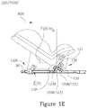
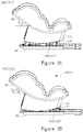
- FIGs 1C-1E schematically illustrate impact handling system 100 at normal (no-impact) state 101 ( Figure 1C ) and at impacted states 102A, 102B, namely under frontal impact 80A ( Figure 1D ) and under impact 80B from the rear ( Figure 1E , also Figure 1B ).
- connections 130 and 130A move to control the trajectory of dynamic element 131 and dynamic part 95 in a way that, in addition to restraining the movement of dynamic part 95 relative to static part 90, also converts at least a part of a horizontal component of impacts 80A or 80B, respectively, into a vertical force component applied to dynamic part 95 in order to prevent or reduce damage to a person on dynamic part 95 upon the respective impact by redirecting the stress applied upon the person to comply better with the person's anatomical structure and tolerances. For example, changing the person's orientation may reduce compression forces applied to the spine due to the impact and to which the spine is more vulnerable than to tensile forces.
- restraining the movement as well as redirecting the forces may be utilized to redesign static part 90 and/or dynamic part 95 to improve their energy absorbing capability as well, and/or to reduce their respective weights or design them according to the anticipated force application, as regulated by impact handling system 100.
- impact handling system 100 and connections 130, 130A may be configured to exhibit angles ⁇ 0 , ⁇ 1 (A), ⁇ 1 (B) and ⁇ 0 , ⁇ 1 (A), ⁇ 1 (B) that control ⁇ to increase from ⁇ 0 to ⁇ 1 (A) and ⁇ 1 (B) (i.e., ⁇ 0 ⁇ ⁇ 1 (A), ⁇ 1 (B)) upon impact, e.g., from ⁇ 0 ⁇ 30° to ⁇ 1 (A), ⁇ 1 (B) ⁇ 40°
- Angles ⁇ 0 , ⁇ 1 (A), ⁇ 1 (B) and ⁇ 0 , ⁇ 1 (A), ⁇ 1 (B) are determined by the configurations of connections 130, 130A, and specifically by the spatial configuration of the attachment points of static and dynamic elements 135, 131, 132 and of energy absorbing elements 120A, 120B thereto, which may be configured and adapted according to requirements.
- energy absorbing elements 120A, 120B are connected to connection 130 via limiting tracks 123A, 123B respectively which determine the directions and extents of enables movements of the connection points between respective energy absorbing elements 120A, 120B and dynamic elements 132.
- Figures 2A-2E schematically illustrate non-limiting embodiments of impact handling system 100 having a single and central energy absorbing element 120, or two lateral energy absorbing elements 120, connecting static part 90 to dynamic element(s) 131 (and/or 132 ) via connection 130 having arm 136 connecting upper dynamic element 131 connected to dynamic part 95 and lower dynamic element 132 connected to central energy absorbing element 120.
- Figures 2A and 2C illustrate non-impacted state 101
- Figures 2B , 2E illustrate an impacted state 102
- Figure 2D illustrates system 100 's response to smaller impact 80A and/or to an intermediate state of system 100 upon stronger impact 80A.
- Such configurations may be realized by other arrangements of one or more energy absorbing elements 120.
- FIGS 3A-3C are high level illustrations of force calculations and principles of spatial configuration applicable to impact handling system 100. While one or two energy absorbing elements 120, 120A are illustrated in these figures for explanatory reasons, any configuration of energy absorbing elements 120 that is arranged according to the illustrated principles is considered to be included within the scope of the present disclosure.
- FIG. 3A schematically illustrates impact handling system 100 having two sets of connections 130, 130A.
- static element(s) 135 comprises pivot(s) 135 and dynamic element(s) comprises arms 138, 139 hingedly connected to pivot(s) 135 to form a fixed specified angle ⁇ .
- Arm 138 is further connected to energy absorbing element(s) 120 and arm 139 is further connected to dynamic element 131 attached to dynamic part 95 and determines trajectory 140 thereof.
- impact handling system 100 further comprises one or more different sets of connections (130A), in which static element 135 comprises respective pivot 135A and dynamic element 131A comprises one arm 137 hingedly connected to pivot 135A and to dynamic element 131A attached to dynamic part 95 and determines trajectory 140A thereof.
- static element(s) 133, 133A may be at least one track 133, 133A shaped to determine trajectory 140, 140A of dynamic element 131, 131A, respectively, and possibly also convert at least a part of the horizontal component of impact 80 into a vertical force component applied to dynamic part 95 to increase its inclination angle ⁇ .
- the conversion may be carried out by the angular positioning of energy absorbing element(s) 120.
- Figure 3C illustrates energy absorbing element(s) 120 attached directly to dynamic element 131, 131A, which simultaneously restrain dynamic element 131, 131A and attached dynamic part 95, and control respective trajectories 140, 140A thereof to increase its inclination angle ⁇ .
- Tracks 133, 133A may comprise, e.g., groove(s), ridge(s) or cam(s), to guide dynamic elements 131, 131A, respectively.
- the slideway may comprise a plurality of rails configured for sliding the slide in a plurality of directions angularly different from each other.
- Connections 130, 130A may comprise a turning arrangement configured for a smooth rotation of the displaceable member.
- Connections 130, 130A may comprise a six-bar-hinged sub-arrangement configured for controllable linear displacement, having a sub-arrangement with an axis of symmetry passing through two opposite hinges, and with energy absorbing element(s) 120 connecting the opposite hinges.
- At least one of dynamic elements 131, 131A may be a pivoted cam, configured to control forces delivered to dynamic part 95 and its orientation according to similar principles.
- energy absorbing element(s) 120 may operate using various mechanical principles, and absorb some, most or all energy mechanically, by deformation or electromagnetically. Energy absorbing element(s) 120 may be produced by any of casting, injecting, eroding, molding, wire twining, machining, cutting, forming, bending and any combination thereof.
- Energy absorbing element(s) 120 may comprise any of: an elongated spiral, a crushable column, a rolling torus, an inversion tube, a cutting shock absorber, a slitting shock absorber, a tube-and-die absorber, a rolling absorber, a flattening-tube absorber, a strap bender absorber, a rod bender absorber, a wire bender absorber, a wire-through-platen absorber, a deformable link absorber, an elongating a tube/strap/cable absorber, a tube flaring, a housed coiled cable absorber, a bar-through-die absorber, a hydraulic absorber, a pneumatic absorber and combinations thereof.
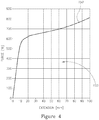
- Figure 4 is an example for an extension-force diagram that characterizes energy absorbing element(s) 120.
- Curve 150 presenting the force applied by energy absorbing element 120 as a function of its extension (or displacement of its connection point to dynamic element 132 ) may be controlled and modified by configuring e.g., the dimensions of energy absorbing element(s) 120 such as length, width, thickness, form, type of cut and parameters of spiral windings, in case energy absorbing element(s) 120 are configured according to WIPO Publication No. 2013046200 (see below).
- Curve 150 denotes the force S applied by energy absorbing element(s) 120 onto connection 130 (see Figure 3A ) and configuring curve 150 enables control of the changes of the angles in impact handling system 100 upon varying impacts, as well control of strength requirements applicable to static part 90 and dynamic part 95. Furthermore, area 155 below curve 150 schematically illustrates the energy absorbed by energy absorbing element(s) 120 as it extends, and hence the reduction in impact energy. Specifically, either or both static part 90 and dynamic part 95 may be designed to take reduced forces and absorbed energy into account, to relief structural requirements thereupon.
- Curve 150 may be modified according to the specific application scenarios, including number and positioning of energy absorbing element(s) 120, characteristics of person occupying the seat (e.g., grown up, child or baby) etc.
- Curve 150 may also be adapted according to auxiliary energy absorption mechanisms which are involved, e.g., the positions and specifications of seat belts.
- Figures 5A-5C are high level schematic illustrations of impact handling system 100.
- Figures 5A-5C schematically illustrates impact handling principles and a variety of schematic configurations, the details of which may be adapted to specific circumstances.
- Figures 5A-5C generalize the more specific yet non-limiting embodiments illustrated above.
- Impact handling system 100 comprises dynamic part 95 mounted on static part 90 and at least one energy absorbing element 120 configured to restrain a movement of dynamic part 95 relative to static part 90 upon impact 80 (see Figure 3A ).
- System 100 further comprises at least one connection 130 between static and dynamic parts 90, 95 (respectively).
- Connection(s) 130 (and 130A ) has static element(s) 135 attached to static part 90 and dynamic element(s) 131 (and 132 ) attached to dynamic part 95.
- Energy absorbing element(s) 120 120A, 120B) is connecting static part 90 to dynamic element(s) 131 (and/or 132 ).
- Static element(s) 135 is configured to control a trajectory 140 (and 140A, see Figures 3A-3C ) of dynamic element(s) 131 in a way that converts at least a part of a horizontal component of the impact into a vertical force component applied to dynamic part 95 (see Figure 3A ).
- Dynamic part 95 may be a seat and static part 90 may be a basis (e.g., an ISOFIX basis) onto which the seat is mounted (as illustrated above, and see e.g., Figures 5A, 5C ) or dynamic part 95 may be a seat back and static part 90 may be a seat base (see e.g., Figure 5B ).
- basis e.g., an ISOFIX basis
- dynamic part 95 may be a seat back and static part 90 may be a seat base (see e.g., Figure 5B ).
- Configuration of impact handling system 100 and specifically of connections 130, 130A may be carried out with respect to available free volumes around static and dynamic parts 90, 95, such as components of a seat system.
- FIGS 5A-5B schematically illustrate conceptual configurations, with dynamic element(s) 131 represented by a circle which is optionally connected by an extension 136 to other dynamic element(s) 132 (represented by another circle) at a different location.
- the relative positions of dynamic elements 131, 132 and the nature and form of extension 136 may be configured to control trajectories 140 of dynamic elements 131, 132 and therefor dynamic part 95 as well as to convert at least part of an horizontal component of the impact into a vertical force component acting on dynamic part 95 and causing e.g., a change of the angle of dynamic part 95 in order to accommodate the forces acting on a person sitting in the seat to be absorbed better by the person's body.
- FIG. 3A schematically illustrates impact handling system 100 having two sets of connections 130, 130A.
- static element(s) 135 comprises pivot(s) 135 and dynamic element(s) comprises arms 138, 139 hingedly connected to pivot(s) 135 to form a fixed specified angle.
- Arm 138 is further connected to energy absorbing element(s) 120 and arm 139 is further connected to dynamic element 131 attached to dynamic part 95 and determines trajectory 140 thereof.
- impact handling system 100 comprises multiple such sets.
- impact handling system 100 further comprises one or more different sets of connections (130A), in which static element 135 comprises respective pivot 135A and dynamic element 131 comprises one arm 137 hingedly connected to pivot 135A and to dynamic element 131A attached to dynamic part 95 and determines trajectory 140A thereof.
- Figure 5A schematically illustrates embodiments designed according to this principle in an abstract manner, showing extension 136 as representing arms 138, 139.
- extension 136 may be implemented in different ways, e.g., as a cam-like extension, as a multiple bar linkage, as a linear configuration (enabling linear and not angular motions) etc.
- Static element(s) 135 is configured to control a trajectory of dynamic element(s) 131 and the spatial relation between static and dynamic parts 90, 95 during their relative movement due to the impact, in a way that converts at least a part of a horizontal component of the impact into a vertical force component applied to dynamic part 95.
- FIG. 5C schematically illustrates certain embodiments, in which impact handling system 100 comprises two or more opposing energy absorbing elements 120A, 120B configured to restrain movements of dynamic part 95 relative to static part 90 upon impact in either of respective two opposite impact directions 80A, 80B, respectively.
- connection of energy absorbing elements 120A, 120B to static part 90 and to dynamic element 131 (and/or 132 ) may be at one or more connection points, and the spatial configuration of energy absorbing elements 120A, 120B and of static and dynamic elements 135, 131, 132 as well as of extension 136 may be configured to control the trajectory and orientation of dynamic part 95, restrain its movement, reduce the applied forces and convert at least part of an horizontal component of the impact into a vertical force component acting on dynamic part 95 and causing e.g., a change of the angle of dynamic part 95 in order to accommodate the forces acting on a person sitting in the seat to be absorbed better by the person's body.
- the present disclosure elaborates on, and introduces further developments with respect to the disclosure of WIPO Publication No. 2013046200 which teaches energy absorbing devices for carrying a passenger seat; the devices comprise a base fixed to a vehicle; a member displaceable from base; at least one energy-absorbing arrangement interconnecting base and displaceable member.
- the energy-absorbing arrangement comprises a plastically deformable absorbing element in response to stresses greater than a predetermined threshold stress.
- the plastically deformable absorbing element is a helically configured ribbon having spaced-apart ribbon laps.
- the plastically deformable absorbing element is compressible, and/or extendable.
- a method of attenuating the acceleration applied to a passenger due to impact comprises steps of: providing an energy absorbing device fixedly attaching the base to the vehicle; fixedly attaching the passenger seat to the base; accidently applying the impact to the vehicle; displacing the displaceable member relative to the base; attenuating the effect of the impact on the passenger.
- WIPO Publication No. 2013046200 is incorporated herein by reference in its entirety. Any of the presently disclosed principles may be applied to develop and enhance any of the embodiments taught by WIPO Publication No. 2013046200 . Such developments and enhancements are likewise considered part of the resent disclosure.
- energy absorbing elements 120 may comprise any embodiment of the plastically deformable absorbing element which is a helically configured ribbon having spaced-apart ribbon laps, as described in WIPO Publication No. 2013046200 .
- Energy absorbing elements 120 may comprise any other type of energy absorbing element, e.g., ones converting impact energy mechanically (e.g., plastically and/or elastically and in any deformation direction of the element), magnetically, electrically etc. and any combination thereof.
- Any configuration of the plastically deformable absorbing elements taught in WIPO Publication No. 2013046200 may be modified or enhanced according to the presently disclosed principles and embodiments.
- any form of connection 130 between energy absorbing elements 120 and dynamic part 95 (such as the seat of WIPO Publication No.
- connections 130 may be constructed by enhancing any of the mechanisms taught in figures 12-39 and the associated description of WIPO Publication No. 2013046200 according to the principles disclosed in the present invention, all such modifications and enhancements are thus included in the present disclosure.
- the energy absorption requirement for the safety seat system may be split between the seat, base and the absorbing elements, relaxing the energy absorption requirement for the seat and/or the base.
- using energy absorbing elements 120 may allow producing lighter seats, which nevertheless satisfy the safety requirements when used with energy absorbing elements 120.
- the seat and base may be reconfigured according to forces applied via absorbing elements 120 and thus improve the seat's responses to impacts, utilizing the fact that application of absorbing elements 120 also makes the directions of force application due to impact more predictable. Any seat and basis configuration that is designed and produced according to the disclosed principles is considered part of the present disclosure.
- FIG. 6 is a high level schematic flowchart, schematically illustrating an impact handling method 200.
- Impact handling method 200 may comprise connecting a static part (e.g., a basis or a seat base) to a dynamic part mounted thereupon (e.g., a seat or a seat back) by at least one static element connected to at least one dynamic element attached to the respective parts (stage 210 ), connecting the at least one dynamic element to the static part by at least one energy absorbing element (stage 220 ), configuring the energy absorbing element(s) to restrain, upon impact, a movement of the dynamic part relative to the static part (stage 230 ) and configuring the static element(s) to control a trajectory of the dynamic element(s) in a way that converts at least a part of a horizontal component of the impact into a vertical force component applied to the dynamic part (stage 240 ).
- a static part e.g., a basis or a seat base
- a dynamic part mounted thereupon e.g.,
- Method 200 may comprise configuring the static element(s) to comprise at least one pivot and the dynamic element(s) to comprise at least one pair of arms hingedly connected to the pivot(s) to form fixed specified angle(s) (stage 270 ).
- Method 200 may comprise connecting one arm of the pair(s) to the energy absorbing element(s) and another arm to the dynamic element(s) attached to the dynamic part to determine the trajectory thereof (stage 275 ).
- Method 200 may comprise configuring the static element(s) to comprise respective at least one pivot and the dynamic element(s) to comprise at least one arm hingedly connected to the pivot(s) and to the dynamic element(s) attached to the dynamic part to determine the trajectory thereof (stage 280 ).
- Method 200 may comprise connecting the dynamic element(s) to the static part by at least two energy absorbing elements configured to restrain a movement of the dynamic part relative to the static part upon impact in either of respective two opposite impact directions (stage 290 ).
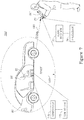
- dynamic part 95 may comprise a baby or child seat 95 or a vehicle seat 96, situated in a vehicle 60, as illustrated in the following Figure 7 .
- Embodiments comprise any combination of impact handling systems 100 and method 200 disclosed above, with ultrasound alerting systems 160 and methods 300 disclosed below.
- signal 190 may comprise a sequence of discrete signal elements (e.g., pulses), wherein any or both of the sequence and its elements may be modified to indicate the seat statuses, e.g., in a Morse-code-like fashion or according to any scheme that associates seat statuses with signal modulation patterns.
- sequence of discrete signal elements e.g., pulses
- any or both of the sequence and its elements may be modified to indicate the seat statuses, e.g., in a Morse-code-like fashion or according to any scheme that associates seat statuses with signal modulation patterns.
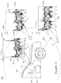
- Figure 8 is a high level schematic illustration of ultrasound signal detection at different distances, according to some embodiments of the invention.
- a transmission intensity of ultrasound transmitter 170 may be configured to be detectable by audio receiver 75 up to a specified range 180, in non-limiting examples, up to 10 meters.
- a signal to noise ratio may be design to fade away signal 190 in the surrounding noise beyond range 180.
- the transmission intensity may be configured to be detectable only within vehicle 60, and/or the transmission intensity may be configured to be undetectable outside vehicle 60 when the doors are shut.
- detection may be configured to depend ton vehicle status, e.g., whether vehicle doors are open or shut, whether vehicle 60 is locked, standing or moving etc. Delays may be introduced between signal detection, or detection failures, and the actual activation of alert 197, for example, a specified time period may be allowed between closing the vehicle doors and activation of alert 197.
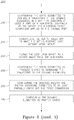
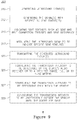
- Ultrasound alerting method 300 may comprise generating at least one ultrasound signal (stage 310 ), for example with respect to at least one seat status (stage 312 ), transmitting the generated at least one ultrasound signal at at least one specified frequency (stage 320 ), detecting, at an audio receiver of a user's communication device, the transmitted at least one ultrasound signal (stage 330 ), and indicating signal reception (stage 335 ) and/or generating at least one alert associated with a failure to detect the at least one ultrasound signal (stage 340 ).
- Method 300 may comprise indicating the seat status(es) (stage 345 ).
- Method 300 may further comprise selecting the at least one specified frequency to be receivable by the audio receiver.
- method 300 further comprises configuring a transmission intensity to be detectable by the device's audio receiver up to a specified range up to ten meters (stage 325 ), in some embodiments. In certain embodiments, method 300 comprises configuring the transmission intensity to be detectable only within the vehicle (stage 327 ) and/or configuring the transmission intensity to be undetectable outside the vehicle when the doors are shut (stage 328 ).
Landscapes
- Engineering & Computer Science (AREA)
- Mechanical Engineering (AREA)
- Transportation (AREA)
- Aviation & Aerospace Engineering (AREA)
- General Health & Medical Sciences (AREA)
- Child & Adolescent Psychology (AREA)
- Health & Medical Sciences (AREA)
- Business, Economics & Management (AREA)
- General Physics & Mathematics (AREA)
- Physics & Mathematics (AREA)
- Emergency Management (AREA)
- Computer Networks & Wireless Communication (AREA)
- Seats For Vehicles (AREA)
Description
- The present invention relates to the field of safety devices, and more particularly, to energy absorbing, impact handling systems associated with ultrasound-based children safety alerts.
- Impact energy is often harming and destructive. A special case is a seat system in a vehicle, onto which impacts due to accidents may prove life threatening.
- Proper use of vehicle seats, especially baby seats, as well as the need for assuring babies are not forgotten in vehicles are two major issues in vehicle-related children safety requirements. Known systems utilize communication channels such as cellular, WiFi and Bluetooth to communicate with a user's smartphone. For example,
U.S. Patent Publication No. 2013049955 , which is incorporated herein by reference in its entirety, discloses an approach for providing notifications to caregivers based on the detected presence of a child in a car seat is described. Physical presence of an object within a car seat is detected. A determination is made that a proximity threshold between a mobile device and the car seat is satisfied based on the presence information, range information associated with the mobile device, or a combination thereof. A notification message is generated in response to the detected physical presence of the object to indicate the presence of the object in the car seat based on the determination. Initiation of the transmission of the notification message to a mobile device within a predetermined proximity of the car seat is performed. -
U.S. Patent Publication No.: 2012/089299 discloses a vehicle with wireless sensors that includes a frame, at least one sensor assembly fixed to the frame and each including a sensor arranged to obtain data about a condition or property of the vehicle or part thereof, and a wireless transmission component coupled to the sensor for wirelessly transmitting a signal derived from the data obtained by the sensor, a receiver fixed to the frame arranged to receive signals from the wireless transmission component, and a reactive component for performing an action based on the data obtained by the sensor and transmitted from the wireless transmission component to the receiver. -
U.S. Patent Publication No.: 2006/208169 discloses a system and method for obtaining information about occupancy of a compartment in a movable object in which at least first and second optical imagers obtain images of a common area of the compartment and spaced apart from one another. A processing circuitry can be arranged to determine the distance of the feature from the imagers by triangulation. -
U.S. Patent Publication No.: 2008/157940 discloses a vehicle including a first substructure and a second substructure arranged such that an interior space is defined by or between the first and second substructures, and an arrangement for determining whether an object is present in the interior space. The arrangement includes ultrasonic transducers arranged on the second substructure and to transmit ultrasonic waves toward the first substructure and receive any waves reflected by objects in the interior space and a processor coupled to the ultrasonic transducers and arranged to determine whether an object is present in the interior space based on reception of waves by the ultrasonic transducers. -
U.S. Patent Publication No.: 20110095940 discloses an arrangement and method for monitoring inanimate objects in an interior thereof that includes a sensor system arranged to obtain data about the object by applying micropower impulse radar (MIR) transmissions into the interior of the asset. The communication system transmits the data about each object obtained by the sensor system and the location of the asset provided by the location determining system to one or more remote facilities, these remote facilities being those interested in the information about the objects in the asset being monitored. - International Patent Publication No.:
WO2006113734 discloses a wireless, self-activating, proximity warning system utilizes an on-board computer of an automobile and a GPS locating system to sending a warning signal to a vehicle operator that a child has been left buckled and unattended in an infant seat. A transmitter associated with the child seat transmits coded RF signals of certain strength to a receiver carried by the operator. The receiver triggers an alarm when the signal strength or time between transmitted signals indicates that the operator has gone beyond a permitted range.U.S. Patent Publication No.: 2007/085697 discloses a vehicular seat including a weight determining system for obtaining an indication of the weight of an occupying item in the seat includes a seat support structure, a cushion arranged on the seat support structure, and a sensor system arranged to sense the downward deflection of the cushion and convert the downward deflection into an indication of the weight of the occupying item. -
U.S. Patent Publication No.: 2008/189053 discloses an arrangement and method for analyzing weight of an occupying item in a seat that includes one or more weight sensors arranged to obtain a measurement of the force applied to the seat, a forcing function determination arrangement for measuring a forcing function of the seat and a processor coupled to the weight sensor(s) and forcing function determination arrangement for receiving the measurement of the force applied to the weight sensor(s) and the measurement of the forcing function from the forcing function measurement system and determining the weight of the occupying item based thereon. -
U.S. Patent Publication No.: 2005/192727 discloses a sensor assembly capable of obtaining and providing a measurement of a physical quantity that includes an antenna capable of receiving a radio frequency signal, a radio frequency identification (RFID) device coupled to the antenna, a sensor coupled to the RFID device, and a switch coupled to the RFID device. When the antenna receives the particular signal associated with the RFID device, the RFID device causes the switch to close and connect the sensor in the circuit with the antenna to enable the measurement generated by the sensor to be directed to and transmitted by the antenna. -
U.S. Patent Publication No.: 2013/033373 discloses a method and system for a car seat buckle with a transmitter to a portable alarm unit such as a key ring (D9, Abstract). The system may include an alarm generation module adapted to receive an engagement signal from the buckle and generate an alarm signal upon detection of an alarm condition. - The ultrasound alerting system according to the invention comprises an ultrasound transmitter (170) having a transmission intensity configured to be detectable within a specified range (180), the ultrasound transmitter (170) is configured to transmit at least one ultrasound signal at at least one specified frequency, wherein the at least one ultrasound signal is associated with at least one baby seat status of a baby seat (95) in a vehicle, a controller (175) associated with the baby seat (95) and configured to generate the at least one ultrasound signal with respect to at least one seat baby status and control the transmitter (170) accordingly, and an audio receiver configured to detect the at least one ultrasound signal when the audio receiver (75) is within the specified range (180) and to indicate failure to detect the at least one ultrasound signal, when the audio receiver (75) is outside the specified range (180) and after the detection thereof, to create a respective alert (197).
- These, additional, and/or other aspects and/or advantages of the present invention are set forth in the detailed description which follows; possibly inferable from the detailed description; and/or learnable by practice of the present invention.
- For a better understanding of embodiments of the invention and to show how the same may be carried into effect, reference will now be made, purely by way of example, to the accompanying drawings in which like numerals designate corresponding elements or sections throughout.
- In the accompanying drawings:
-
Figures 1A-1E and2A-2E are high level schematic illustrations of an impact handling system. -
Figures 3A-3C are high level illustrations of force calculations and principles of spatial configuration applicable to impact handling system. -
Figure 4 is an example for an extension-force diagram that characterizes energy absorbing element(s). -
Figures 5A-5B schematically illustrate conceptual configurations of the impact handling system. -
Figure 6 is a high level schematic flowchart, schematically illustrating an impact handling method. -
Figure 7 is a high level schematic illustration of an ultrasound alerting system, according to some embodiments of the invention. -
Figure 8 is a high level schematic illustration of ultrasound signal detection at different distances, according to some embodiments of the invention. -
Figure 9 is a high level schematic flowchart of an ultrasound alerting method, according to some embodiments of the invention. - Prior to the detailed description being set forth, it may be helpful to set forth definitions of certain terms that will be used hereinafter.
- The term "dynamic" as used in this application with respect to parts or elements refers to their ability to move in a controlled manner upon impact.
- With specific reference now to the drawings in detail, it is stressed that the particulars shown are by way of example and for purposes of illustrative discussion of the preferred embodiments of the present invention only, and are presented in the cause of providing what is believed to be the most useful and readily understood description of the principles and conceptual aspects of the invention. In this regard, no attempt is made to show structural details of the invention in more detail than is necessary for a fundamental understanding of the invention, the description taken with the drawings making apparent to those skilled in the art how the several forms of the invention may be embodied in practice.
- Before at least one embodiment of the invention is explained in detail, it is to be understood that the invention is not limited in its application to the details of construction and the arrangement of the components set forth in the following description or illustrated in the drawings. The invention is applicable to other embodiments or of being practiced or carried out in various ways. Also, it is to be understood that the phraseology and terminology employed herein is for the purpose of description and should not be regarded as limiting.
- Impact handling systems and respective methods are provided, which comprise a dynamic part mounted on a static part and energy absorbing element(s) configured to restrain a movement of the dynamic part relative to the static part upon impact. The system further comprises connection(s) between the static and dynamic parts which have static element(s) attached to the static part and dynamic element(s) attached to the dynamic part. The energy absorbing element(s) is connecting the static part to the dynamic element(s), and the static element(s) is configured to restrain a movement of the dynamic part relative to the static part upon impact in opposite impact directions and/or to control a trajectory of the dynamic element(s) in a way that converts at least a part of a horizontal component of the impact into a vertical force component applied to the dynamic part.
-
Figures 1A-1E and2A-2E are high level schematic illustrations of animpact handling system 100.Figures 3A-3C are high level illustrations of force calculations and principles of spatial configuration applicable toimpact handling system 100.Figures 3A-3C demonstrate in a non-limiting manner various embodiments and configuration principles forimpact handling system 100, whileFigures 1A-1E and2A-2E exemplify concrete yet non-limiting examples for implementations of some embodiments of these principles. -
Impact handling system 100 comprises a dynamic part 95 (such as a seat) mounted on a static part 90 (such as a basis) and at least oneenergy absorbing element 120 configured to restrain a movement ofdynamic part 95 relative tostatic part 90 upon impact 80 (seeFigure 3A ).System 100 further comprises at least oneconnection 130 between static anddynamic parts 90, 95 (respectively). Connection(s) 130 (and 130A) has static element(s) 135 attached tostatic part 90 and dynamic element(s) 131 (and 132) attached todynamic part 95. Energy absorbing element(s) 120 (120A, 120B) is connectingstatic part 90 to dynamic element(s) 131 (and/or 132), possibly, usingmovable connections 123, e.g.,connections Figures 3A-3C ) of dynamic element(s) 131 in a way that converts at least a part of a horizontal component of the impact into a vertical force component applied to dynamic part 95 (seeFigure 3A ). - For example,
Figures 1A and 1B schematically illustrateimpact handling system 100 having two sets ofconnections Connections 130A comprise static element(s) 135A, comprising respective pivot(s) 135A, and dynamic element(s) 131A (and 132A), hingedly connected to pivot(s) 135A and attached todynamic part 95.Connections 130 comprise static element(s) 135, comprising at least onepivot 135, and dynamic element(s) 131 (and 132), hingedly connected to pivot(s) 135 and toenergy absorbing elements static part 90. In the embodiments illustrated inFigures 1A and 1B ,energy absorbing elements dynamic part 95 relative tostatic part 90 upon impact in either of respective two opposite impact directions.Connections dynamic part 95 upon impact in either direction. As an illustration,Figures 1A and 1B schematically depict basis 110 (e.g.,basis 110 for seat 95) ofimpact handling system 100 before and after impact, asstates 111 and 112 respectively, withenergy absorbing elements non-extended states 121 andenergy absorbing element 120B inextended state 122 upon absorbingrear impact 80B. -
Figures 1C-1E schematically illustrateimpact handling system 100 at normal (no-impact) state 101 (Figure 1C ) and atimpacted states frontal impact 80A (Figure 1D ) and underimpact 80B from the rear (Figure 1E , alsoFigure 1B ). Under both impacts,connections dynamic element 131 anddynamic part 95 in a way that, in addition to restraining the movement ofdynamic part 95 relative tostatic part 90, also converts at least a part of a horizontal component ofimpacts dynamic part 95 in order to prevent or reduce damage to a person ondynamic part 95 upon the respective impact by redirecting the stress applied upon the person to comply better with the person's anatomical structure and tolerances. For example, changing the person's orientation may reduce compression forces applied to the spine due to the impact and to which the spine is more vulnerable than to tensile forces. - In certain embodiments, restraining the movement as well as redirecting the forces may be utilized to redesign
static part 90 and/ordynamic part 95 to improve their energy absorbing capability as well, and/or to reduce their respective weights or design them according to the anticipated force application, as regulated byimpact handling system 100. - Trajectory control, illustrated in
Figures 3A-3C below as well, is evident inFigures 1C-1E upon considering the orientations ofdynamic part 95 andconnections connection 130A, from δ0 instate 101 to δ1(A) and δ1(B) in forward and rear impact states 102A, 102B respectively; the changes in angle θ between the vertical andconnection 130, from θ0 instate 101 to θ1(A) and θ1(B) in forward and rear impact states 102A, 102B respectively; and the resulting changes in the inclination angle ε ofdynamic part 95 from ε0 instate 101 to ε1(A) and ε1(B) in forward and rear impact states 102A, 102B respectively (the angles are exemplified for certain impact values, and clearly depend thereupon - specific values may be configured according to specified ranges of impact forces). Specifically, in certain embodiments,impact handling system 100 andconnections - Angles δ0, δ1(A), δ1(B) and θ0, θ1(A), θ1(B) are determined by the configurations of
connections dynamic elements energy absorbing elements energy absorbing elements connection 130 via limitingtracks energy absorbing elements dynamic elements 132. For example, in the non-limiting illustrated example, the connection ofenergy absorbing element 120B todynamic element 132 is designed to rise whileenergy absorbing element 120B elongates upon energy absorption thereby, uponrear impact 80B (Figure 1E ) and thereby increase inclination angle ε ofdynamic part 95. In certain embodiments, illustrated below inFigures 2A-2E , the connection ofenergy absorbing element 120 todynamic element 132 is designed to sink upon energy absorption byenergy absorbing element 120 uponfrontal impact 80A (Figures 2B ,2E ) and thereby increase inclination angle ε ofdynamic part 95 from ε0 to ε1>ε0 (Figures 2A, 2B ). In a non-limiting example, ε0 may be around 25° while ε1 may reach 40°. The system configuration may be arranged to control the seat's trajectory to make the sitting posture more upright upon impact, e.g., by tilting the seat upon impact to a larger angle from the horizontal. -
Figures 2A-2E schematically illustrate non-limiting embodiments ofimpact handling system 100 having a single and centralenergy absorbing element 120, or two lateralenergy absorbing elements 120, connectingstatic part 90 to dynamic element(s) 131 (and/or 132) viaconnection 130 havingarm 136 connecting upperdynamic element 131 connected todynamic part 95 and lowerdynamic element 132 connected to centralenergy absorbing element 120.Figures 2A and2C illustratenon-impacted state 101,Figures 2B ,2E illustrate an impactedstate 102 andFigure 2D illustratessystem 100's response tosmaller impact 80A and/or to an intermediate state ofsystem 100 uponstronger impact 80A. Such configurations may be realized by other arrangements of one or moreenergy absorbing elements 120. - Central
energy absorbing element 120 plastically extends uponimpact 80A (Figures 2B ,2E ) to absorb energy and restrain the movement ofdynamic part 95 relative tostatic part 90, and is connected to increase inclination angle ε ofdynamic part 95 by controlling the trajectory ofdynamic element impact 80A into a vertical force component applied todynamic part 95. -
Figures 3A-3C are high level illustrations of force calculations and principles of spatial configuration applicable toimpact handling system 100. While one or twoenergy absorbing elements energy absorbing elements 120 that is arranged according to the illustrated principles is considered to be included within the scope of the present disclosure. -
Figure 3A schematically illustratesimpact handling system 100 having two sets ofconnections arms Arm 138 is further connected to energy absorbing element(s) 120 andarm 139 is further connected todynamic element 131 attached todynamic part 95 and determinestrajectory 140 thereof. In certain embodiments,impact handling system 100 further comprises one or more different sets of connections (130A), in whichstatic element 135 comprisesrespective pivot 135A anddynamic element 131A comprises onearm 137 hingedly connected to pivot 135A and todynamic element 131A attached todynamic part 95 and determinestrajectory 140A thereof. - On the basis of
Figure 3A , the following calculations and considerations are presented to illustrate the design principles ofimpact handling system 100. The following calculations serve illustration purposes and are hence simplified. Specifically, the illustrative calculations assume constantlyhorizontal impact 80, no friction and applies a quasi-static calculation. Referring todynamic part 95 alone, the quasi-static calculation assuming zero overall moment with respect to point R, ∑MR=0 implies F·(c-a·sin(α))=P·b·sin(β) according to dimension annotation of lengths and angles appearing inFigure 3A (F being impact 80 and P being the force applied atconnection 130A). Defining A as P/F=(c-a·sin(α))/b·sin(β), and assuming zero overall moment with respect to point J (135), ∑MJ=0 implies F·[c-a·sin(α)+d·cos(θ)]=P·1·sin(δ)+S·x·sin(γ) according to dimension annotation of lengths and angles appearing inFigure 3A (S being the force applied byenergy absorbing element 120 at connection 130). After substituting P for A·F, the following relation results: S=F·[c-a·sin(α)+d·cos(θ)-A·1·sin(δ)]/[x·sin(γ)]. This relation allows effecting α, θ and β by controlling the other angles and lengths inimpact handling system 100, to essentially increase inclination angle ε ofdynamic part 95 upon impact 80 (e.g. from ca. 25° to ca. 40° upon maximal impact). -
Figures 3B and 3C schematically illustrate additional configurations of static element(s) 133, 133A anddynamic elements impact handling system 100 and particularly additional embodiments of controllingtrajectories dynamic elements impact 80 into a vertical force component applied todynamic part 95.Dynamic elements Figure 3A as well asFigures 1A-1E ,Figures 2A- 2E andFigures 5A-5C below. - In certain embodiments, static element(s) 133, 133A may be at least one
track trajectory dynamic element impact 80 into a vertical force component applied todynamic part 95 to increase its inclination angle ε. Alternatively or additionally, the conversion may be carried out by the angular positioning of energy absorbing element(s) 120.Figure 3C illustrates energy absorbing element(s) 120 attached directly todynamic element dynamic element dynamic part 95, and controlrespective trajectories Tracks dynamic elements -
Connections 2013046200 . For example,connections Connections Connections - In certain embodiments (not shown), at least one of
dynamic elements dynamic part 95 and its orientation according to similar principles. In certain embodiments, energy absorbing element(s) 120 may operate using various mechanical principles, and absorb some, most or all energy mechanically, by deformation or electromagnetically. Energy absorbing element(s) 120 may be produced by any of casting, injecting, eroding, molding, wire twining, machining, cutting, forming, bending and any combination thereof. Energy absorbing element(s) 120 may comprise any of: an elongated spiral, a crushable column, a rolling torus, an inversion tube, a cutting shock absorber, a slitting shock absorber, a tube-and-die absorber, a rolling absorber, a flattening-tube absorber, a strap bender absorber, a rod bender absorber, a wire bender absorber, a wire-through-platen absorber, a deformable link absorber, an elongating a tube/strap/cable absorber, a tube flaring, a housed coiled cable absorber, a bar-through-die absorber, a hydraulic absorber, a pneumatic absorber and combinations thereof. -
Figure 4 is an example for an extension-force diagram that characterizes energy absorbing element(s) 120.Curve 150, presenting the force applied byenergy absorbing element 120 as a function of its extension (or displacement of its connection point to dynamic element 132) may be controlled and modified by configuring e.g., the dimensions of energy absorbing element(s) 120 such as length, width, thickness, form, type of cut and parameters of spiral windings, in case energy absorbing element(s) 120 are configured according to WIPO Publication No.2013046200 (see below).Curve 150 denotes the force S applied by energy absorbing element(s) 120 onto connection 130 (seeFigure 3A ) andconfiguring curve 150 enables control of the changes of the angles inimpact handling system 100 upon varying impacts, as well control of strength requirements applicable tostatic part 90 anddynamic part 95. Furthermore,area 155 belowcurve 150 schematically illustrates the energy absorbed by energy absorbing element(s) 120 as it extends, and hence the reduction in impact energy. Specifically, either or bothstatic part 90 anddynamic part 95 may be designed to take reduced forces and absorbed energy into account, to relief structural requirements thereupon. -
Curve 150 may be modified according to the specific application scenarios, including number and positioning of energy absorbing element(s) 120, characteristics of person occupying the seat (e.g., grown up, child or baby) etc. -
Curve 150 may also be adapted according to auxiliary energy absorption mechanisms which are involved, e.g., the positions and specifications of seat belts. -
Figures 5A-5C are high level schematic illustrations ofimpact handling system 100.Figures 5A-5C schematically illustrates impact handling principles and a variety of schematic configurations, the details of which may be adapted to specific circumstances.Figures 5A-5C generalize the more specific yet non-limiting embodiments illustrated above. -
Impact handling system 100 comprisesdynamic part 95 mounted onstatic part 90 and at least oneenergy absorbing element 120 configured to restrain a movement ofdynamic part 95 relative tostatic part 90 upon impact 80 (seeFigure 3A ).System 100 further comprises at least oneconnection 130 between static anddynamic parts 90, 95 (respectively). Connection(s) 130 (and 130A) has static element(s) 135 attached tostatic part 90 and dynamic element(s) 131 (and 132) attached todynamic part 95. Energy absorbing element(s) 120 (120A, 120B) is connectingstatic part 90 to dynamic element(s) 131 (and/or 132). Static element(s) 135 is configured to control a trajectory 140 (and 140A, seeFigures 3A-3C ) of dynamic element(s) 131 in a way that converts at least a part of a horizontal component of the impact into a vertical force component applied to dynamic part 95 (seeFigure 3A ). -
Dynamic part 95 may be a seat andstatic part 90 may be a basis (e.g., an ISOFIX basis) onto which the seat is mounted (as illustrated above, and see e.g.,Figures 5A, 5C ) ordynamic part 95 may be a seat back andstatic part 90 may be a seat base (see e.g.,Figure 5B ). - Configuration of
impact handling system 100 and specifically ofconnections dynamic parts -
Figures 5A-5B schematically illustrate conceptual configurations, with dynamic element(s) 131 represented by a circle which is optionally connected by anextension 136 to other dynamic element(s) 132 (represented by another circle) at a different location. The relative positions ofdynamic elements trajectories 140 ofdynamic elements dynamic part 95 as well as to convert at least part of an horizontal component of the impact into a vertical force component acting ondynamic part 95 and causing e.g., a change of the angle ofdynamic part 95 in order to accommodate the forces acting on a person sitting in the seat to be absorbed better by the person's body. - As shown above,
Figure 3A schematically illustratesimpact handling system 100 having two sets ofconnections arms Arm 138 is further connected to energy absorbing element(s) 120 andarm 139 is further connected todynamic element 131 attached todynamic part 95 and determinestrajectory 140 thereof. In certain embodiments,impact handling system 100 comprises multiple such sets. In certain embodiments,impact handling system 100 further comprises one or more different sets of connections (130A), in whichstatic element 135 comprisesrespective pivot 135A anddynamic element 131 comprises onearm 137 hingedly connected to pivot 135A and todynamic element 131A attached todynamic part 95 and determinestrajectory 140A thereof.Figure 5A schematically illustrates embodiments designed according to this principle in an abstract manner, showingextension 136 as representingarms extension 136 may be implemented in different ways, e.g., as a cam-like extension, as a multiple bar linkage, as a linear configuration (enabling linear and not angular motions) etc. -
Figure 5B schematically illustrates certain embodiments, in whichimpact handling system 100 connects seat base asstatic part 90 and seat back asdynamic part 95 and comprises one or more energy absorbing element(s) 120 configured to restrain a movement ofdynamic part 95 relative tostatic part 90 uponimpact 80. Connection(s) 130 has static element(s) 135 attached tostatic part 90 and dynamic element(s) 131 attached todynamic part 95. Energy absorbing element(s) 120 is connectingstatic part 90 to dynamic element(s) 131. Static element(s) 135 is configured to control a trajectory of dynamic element(s) 131 and the spatial relation between static anddynamic parts dynamic part 95. -
Figure 5C schematically illustrates certain embodiments, in whichimpact handling system 100 comprises two or more opposingenergy absorbing elements dynamic part 95 relative tostatic part 90 upon impact in either of respective twoopposite impact directions energy absorbing elements static part 90 and to dynamic element 131 (and/or 132) may be at one or more connection points, and the spatial configuration ofenergy absorbing elements dynamic elements extension 136 may be configured to control the trajectory and orientation ofdynamic part 95, restrain its movement, reduce the applied forces and convert at least part of an horizontal component of the impact into a vertical force component acting ondynamic part 95 and causing e.g., a change of the angle ofdynamic part 95 in order to accommodate the forces acting on a person sitting in the seat to be absorbed better by the person's body. - The present disclosure elaborates on, and introduces further developments with respect to the disclosure of WIPO Publication No.
2013046200 which teaches energy absorbing devices for carrying a passenger seat; the devices comprise a base fixed to a vehicle; a member displaceable from base; at least one energy-absorbing arrangement interconnecting base and displaceable member. The energy-absorbing arrangement comprises a plastically deformable absorbing element in response to stresses greater than a predetermined threshold stress. In some embodiments the plastically deformable absorbing element is a helically configured ribbon having spaced-apart ribbon laps. In other embodiments the plastically deformable absorbing element is compressible, and/or extendable. A method of attenuating the acceleration applied to a passenger due to impact is disclosed; the method comprises steps of: providing an energy absorbing device fixedly attaching the base to the vehicle; fixedly attaching the passenger seat to the base; accidently applying the impact to the vehicle; displacing the displaceable member relative to the base; attenuating the effect of the impact on the passenger. Hence, WIPO Publication No.2013046200 is incorporated herein by reference in its entirety. Any of the presently disclosed principles may be applied to develop and enhance any of the embodiments taught by WIPO Publication No.2013046200 . Such developments and enhancements are likewise considered part of the resent disclosure. - Furthermore,
energy absorbing elements 120 may comprise any embodiment of the plastically deformable absorbing element which is a helically configured ribbon having spaced-apart ribbon laps, as described in WIPO Publication No.2013046200 .Energy absorbing elements 120 may comprise any other type of energy absorbing element, e.g., ones converting impact energy mechanically (e.g., plastically and/or elastically and in any deformation direction of the element), magnetically, electrically etc. and any combination thereof. Any configuration of the plastically deformable absorbing elements taught in WIPO Publication No.2013046200 may be modified or enhanced according to the presently disclosed principles and embodiments. Furthermore, any form ofconnection 130 betweenenergy absorbing elements 120 and dynamic part 95 (such as the seat of WIPO Publication No.2013046200 ) may be adapted from and modified with respect to WIPO Publication No.2013046200 . For example,connections 130 may be constructed by enhancing any of the mechanisms taught in figures 12-39 and the associated description of WIPO Publication No.2013046200 according to the principles disclosed in the present invention, all such modifications and enhancements are thus included in the present disclosure. - Advantageously, the energy absorption requirement for the safety seat system may be split between the seat, base and the absorbing elements, relaxing the energy absorption requirement for the seat and/or the base. Thus, using
energy absorbing elements 120 may allow producing lighter seats, which nevertheless satisfy the safety requirements when used withenergy absorbing elements 120. Furthermore, the seat and base may be reconfigured according to forces applied via absorbingelements 120 and thus improve the seat's responses to impacts, utilizing the fact that application of absorbingelements 120 also makes the directions of force application due to impact more predictable. Any seat and basis configuration that is designed and produced according to the disclosed principles is considered part of the present disclosure. -
Figure 6 is a high level schematic flowchart, schematically illustrating animpact handling method 200.Impact handling method 200 may comprise connecting a static part (e.g., a basis or a seat base) to a dynamic part mounted thereupon (e.g., a seat or a seat back) by at least one static element connected to at least one dynamic element attached to the respective parts (stage 210), connecting the at least one dynamic element to the static part by at least one energy absorbing element (stage 220), configuring the energy absorbing element(s) to restrain, upon impact, a movement of the dynamic part relative to the static part (stage 230) and configuring the static element(s) to control a trajectory of the dynamic element(s) in a way that converts at least a part of a horizontal component of the impact into a vertical force component applied to the dynamic part (stage 240). - In certain embodiments,
method 200 may further comprise splitting the energy absorption requirement between the seat, base and the absorbing elements (stage 222), relaxing the energy absorption requirement for the seat and/or the base (stage 225) and reconfiguring the seat and base according to forces applied via the absorbing elements (stage 227). - In certain embodiments,
method 200 may further comprise: controlling the seat's trajectory to make the sitting posture more upright upon impact (stage 245) and tilting the seat upon impact to a larger angle from the horizontal (stage 247). -
Method 200 may further comprise configuring the static element(s) as track(s) shaped to determine the trajectory of the dynamic element(s) (stage 250), and possibly configuring the track(s) and/or the energy absorbing element(s) to at least partially carry out the force conversion (stage 255).Method 200 may further comprise configuring the dynamic element(s) as pivoted cam(s) (stage 260). -
Method 200 may comprise configuring the static element(s) to comprise at least one pivot and the dynamic element(s) to comprise at least one pair of arms hingedly connected to the pivot(s) to form fixed specified angle(s) (stage 270).Method 200 may comprise connecting one arm of the pair(s) to the energy absorbing element(s) and another arm to the dynamic element(s) attached to the dynamic part to determine the trajectory thereof (stage 275). -
Method 200 may comprise configuring the static element(s) to comprise respective at least one pivot and the dynamic element(s) to comprise at least one arm hingedly connected to the pivot(s) and to the dynamic element(s) attached to the dynamic part to determine the trajectory thereof (stage 280). - In certain embodiments,
method 200 may comprise combining two-armed and one-armed configurations to control the trajectory and the force conversion (stage 285). -
Method 200 may comprise connecting the dynamic element(s) to the static part by at least two energy absorbing elements configured to restrain a movement of the dynamic part relative to the static part upon impact in either of respective two opposite impact directions (stage 290). - In certain embodiments,
dynamic part 95 may comprise a baby orchild seat 95 or avehicle seat 96, situated in avehicle 60, as illustrated in the followingFigure 7 . Embodiments comprise any combination ofimpact handling systems 100 andmethod 200 disclosed above, withultrasound alerting systems 160 andmethods 300 disclosed below. -
Figure 7 is a high level schematic illustration of anultrasound alerting system 160, according to some embodiments of the invention.Figure 7 schematically illustrates non-limiting embodiments ofsystem 160 operating in association with ababy seat 95 mounted on avehicle seat 96 in avehicle 60. The term "vehicle seat" as used herein refers to any seat within a vehicle, including both any type of baby orchild seat 95 as well as adult vehicle seats 96. While a common purpose of certain embodiments is generating alerts in case of forgotten babies invehicle 60, orseats 95 attached or operated incorrectly, certain embodiments may comprise generating alerts in other cases, relating to adults using vehicle seats 96. - In certain embodiments,
ultrasound alerting system 160 may comprise anultrasound transmitter 170 configured to transmit at least oneultrasound signal 190 at at least one specified frequency, and anaudio receiver 75 configured to receive at least oneultrasound signal 190 and provide an indication of the signal reception. At least oneultrasound signal 190 may be associated with at least one seat status ofseat 95 and/or 96 invehicle 60.Audio receiver 75 may be further configured to indicate the at least one seat status associated with the received at least one ultrasound signal. The indication may be e.g., an audio signal, an optical signal, a control signal (e.g., to a user's device, to vehicle control elements such as locking control etc.) and/or a communication signal (e.g., to a user's device or to the user via vehicle-related indication elements such as lights or alarm).Audio receiver 75 may simply indicate the reception ofsignal 190, withtransmitter 170 being attached to the person sitting in the seat (e.g., a baby) and/or associated with the respective seat belt.Audio receiver 75 may indicate failure to receivesignal 190, type ofsignal 190 or any other signal related property. -
Ultrasound alerting system 160 may compriseultrasound transmitter 170 configured to transmit at least oneultrasound signal 190 at at least one specified frequency, and acontroller 175 associated withvehicle seat 95 and/or 96 and configured to generate ultrasound signal(s) 190 with respect to at least one seat status andcontrol transmitter 170 accordingly. -
Ultrasound alerting system 160 further comprises an application (e.g., run by a processor 76) installable on a user'scommunication device 70 to be associated with a device'saudio receiver 75 or with astandalone audio receiver 75. The application is configured to detect at least oneultrasound signal 190 and generate at least one alert 197 associated with a failure to detect at least oneultrasound signal 190. - Configurations of
system 160 may comprisetransmitter 170 and/orcontroller 175 associated or embedded inbaby seat 95 and/or invehicle seat 96. Configurations ofsystem 160 may compriseaudio receiver 75 and/orprocessor 76 associated or embedded in user'scommunication device 70 and/or be produced as independent unit(s). In certain embodiments,audio receiver 75 may be associated withvehicle 60 andprocessor 76 may be configured to generatealarm 197 according to a relation between the seat status(es) and the vehicle's state. For example, ifsignal 190 indicates a baby is still inseat 95 andvehicle 60 is not running for a specified duration,system 160 may generaterespective alarm 197 atvehicle 60 and/or at user'sdevice 70. - In certain embodiments,
controller 175 may be associated with any one of: a weight sensor, a belt sensor, a mechanical sensor and an electromagnetic sensor, any of which being configured to indicate respective seat statuses such as a connection status of a seat belt, a connection status ofbaby seat 95 to vehicle 60 (e.g., via vehicle seat 96), a seat occupancy status and any other status indication relating toseats -
Figure 8 is a high level schematic illustration of ultrasound signal detection at different distances, according to some embodiments of the invention. In certain embodiments, a transmission intensity ofultrasound transmitter 170 may be configured to be detectable byaudio receiver 75 up to a specifiedrange 180, in non-limiting examples, up to 10 meters. For example, a signal to noise ratio may be design to fade awaysignal 190 in the surrounding noise beyondrange 180. Alternatively or complementarily, the transmission intensity may be configured to be detectable only withinvehicle 60, and/or the transmission intensity may be configured to be undetectableoutside vehicle 60 when the doors are shut. -
Figure 8 schematically illustratesdisplays 195A-C of receivedsignals 190 with background noise at three different locations ofreceiver 75, as recorded in a demonstrative experiment. Withreceiver 75 withinvehicle 60, displayed receivedsignal 195A comprises aclear ultrasound signal 192A overbackground noise 191A. In the non-limiting illustrated example, ultrasound signals 190 were transmitted at ca. 19kHz and noise level was lower than -66dB while received signals in cases of detection were stronger than -66dB, their strength depending on the distance betweentransmitter 170 andreceiver 75 and vehicle status (e.g., doors open or closed). Withreceiver 75 outsidevehicle 60 but withinrange 180,ultrasound signal 192B is still detectable in displayed received signal 195B overbackground noise 191B. However, outsiderange 180, no clear ultrasound signal is detectable above noise 191C in displayed received signal 195C. Such failure to detect ultrasound signal after former detection thereof is configured to set offalert 197. By configuring the transmission intensity, a distinction between a user being close or invehicle 60 and a user moving away fromvehicle 60 can be made, and used to create respective alerts. In certain embodiments, detection may be configured to depend ton vehicle status, e.g., whether vehicle doors are open or shut, whethervehicle 60 is locked, standing or moving etc. Delays may be introduced between signal detection, or detection failures, and the actual activation ofalert 197, for example, a specified time period may be allowed between closing the vehicle doors and activation ofalert 197. - In certain embodiments,
different alerts 197 may be created for cases such as improper use (e.g., installation) ofseat 95 and/or 96, e.g., incomplete connection (or connection status) of a belt, of an isofix connection betweenseats vehicle 60.Alerts 197 may take any form and/or multiple forms, such as a visual signal (e.g., blinking), a message (e.g., a text message or an on-screen message), an audio signal and a call, e.g., associated with user'scommunication device 70. In case thatmultiple alerts 197 are applicable,system 160 may be configured to prioritizealerts 197 and/or to generate a sequence ofalerts 197 is a specified order, and possibly repeat the sequence. Sequence and alerts' durations may be configured as specified. - In certain embodiments,
processor 76 may fuse data fromaudio receiver 75 and sensors associated withdevice 70 to createcertain alerts 197. For example, alert 197 may be set off upon detection of a seat status such as unbuckled belt and present baby and detection of vehicle movement by the sensors ofdevice 70. - The at least one specified frequency of ultrasound signal(s) 190 is selected to be receivable by
audio receiver 75. Certain embodiments utilize the ability ofaudio receivers 75 such as microphones ofcommunication devices 70 to actually sense audio frequencies much higher than the audible range. For example, ultrasound signal(s) 190 may be at frequencies between 18-24 kHz, between 24-44 kHz and/or around 22 kHz. - Advantageously,
ultrasound alerting system 160 overcomes the prevalent difficulties in electromagnetically-based alerting systems, such as systems operating with cellular communication channels, WiFi or Bluetooth in that it avoids compatibility issues, does not require a bidirectional channel, is much more reliable and uses significantly less energy, which enables more efficient implementation. -
Figure 9 is a high level schematic flowchart of anultrasound alerting method 300, according to some embodiments of the invention. Data processing stages ofmethod 300 may be implemented byprocessor 76 and certain embodiments comprise respective processors, software components and algorithms configured to carry out at least part of the respective stages. -
Ultrasound alerting method 300 may comprise generating at least one ultrasound signal (stage 310), for example with respect to at least one seat status (stage 312), transmitting the generated at least one ultrasound signal at at least one specified frequency (stage 320), detecting, at an audio receiver of a user's communication device, the transmitted at least one ultrasound signal (stage 330), and indicating signal reception (stage 335) and/or generating at least one alert associated with a failure to detect the at least one ultrasound signal (stage 340).Method 300 may comprise indicating the seat status(es) (stage 345).Method 300 may further comprise selecting the at least one specified frequency to be receivable by the audio receiver. - In certain embodiments, the at least one seat status may comprise at least one of: a connection status of a seat belt, a connection status of the seat to the vehicle in case of the seat being a baby seat, and a seat occupancy status.
Method 300 may further comprise modulating the at least one ultrasound signal (stage 317) to indicate any of the at least one seat status (stage 315) such as seat and belt connection statuses and seat occupancy. - In certain embodiments,
method 300 further comprises configuring a transmission intensity to be detectable by the device's audio receiver up to a specified range up to ten meters (stage 325), in some embodiments. In certain embodiments,method 300 comprises configuring the transmission intensity to be detectable only within the vehicle (stage 327) and/or configuring the transmission intensity to be undetectable outside the vehicle when the doors are shut (stage 328). - In certain embodiments,
method 300 may comprise indicating seat statuses with respect to vehicle statuses (stage 347). - Certain embodiments comprise a computer program product comprising a computer readable storage medium having computer readable program embodied therewith, the computer readable program configured to detect, at an audio receiver of a user's communication device, at least one ultrasound signal and generate at least one alert associated with a failure to detect the at least one ultrasound signal. The computer readable program may be further configured to generate, at a vehicle seat, the at least one ultrasound signal with respect to at least one seat status. The computer readable program may be further configured to modulate the at least one ultrasound signal to indicate at least one of: a connection status of a seat belt, a connection status of the seat to the vehicle in case of the seat being a baby seat, and a seat occupancy status.
- In the above description, an embodiment is an example or implementation of the invention. The various appearances of "one embodiment", "an embodiment", "certain embodiments" or "some embodiments" do not necessarily all refer to the same embodiments.
- Although various features of the invention may be described in the context of a single embodiment, the features may also be provided separately or in any suitable combination. Conversely, although the invention may be described herein in the context of separate embodiments for clarity, the invention may also be implemented in a single embodiment.
- Certain embodiments of the invention may include features from different embodiments disclosed above, and certain embodiments may incorporate elements from other embodiments disclosed above. The disclosure of elements of the invention in the context of a specific embodiment is not to be taken as limiting their used in the specific embodiment alone.
- Furthermore, it is to be understood that the invention can be carried out or practiced in various ways and that the invention can be implemented in certain embodiments other than the ones outlined in the description above.
- The invention is not limited to those diagrams or to the corresponding descriptions. For example, flow need not move through each illustrated box or state, or in exactly the same order as illustrated and described.
- Meanings of technical and scientific terms used herein are to be commonly understood as by one of ordinary skill in the art to which the invention belongs, unless otherwise defined.
- While the invention has been described with respect to a limited number of embodiments, these should not be construed as limitations on the scope of the invention, but rather as exemplifications of some of the preferred embodiments. Other possible variations, modifications, and applications are also within the scope of the invention. Accordingly, the scope of the invention should not be limited by what has thus far been described, but by the appended claims and their legal equivalents.
Claims (13)
- An ultrasound alerting system (160) comprising:an ultrasound transmitter (170) having a transmission intensity configured to be detectable within a specified range (180), the ultrasound transmitter (170) being configured to transmit at least one ultrasound signal at at least one specified frequency, wherein the at least one ultrasound signal is associated with at least one baby seat status of a baby seat (95) in a vehicle,a controller (175) associated with the baby seat (95) and configured to generate the at least one ultrasound signal with respect to at least one seat baby status of the baby seat and to control the transmitter (170) accordingly,an audio receiver (75) configured to detect the at least one ultrasound signal when the audio receiver (75) is within the specified range (180) and to indicate failure to detect the at least one ultrasound signal, when the audio receiver (75) is outside the specified range (180) and after the detection thereof, to create a respective alert (197).
- The ultrasound alerting system of claim 1, wherein the at least one alert (197) comprises at least one of: visual signal, an on-screen message, a text message, an audio signal and a call, associated with a user's communication device.
- The ultrasound alerting system of claim 1, wherein the audio receiver (75) and the processor (76) are part of a user's communication device (70) and the application is installable on the user's communication device.
- The ultrasound alerting system of claim 1, wherein the audio receiver and the processor are part of a standalone device arranged to generate the at least one alert. (197).
- The ultrasound alerting system of claim 1, wherein the controller is associated with at least one of: a weight sensor, a belt sensor, a mechanical sensor and an electromagnetic sensor, the respective sensor configured to indicate the at least one seat status.
- The ultrasound alerting system of claim 1, wherein the at least one ultrasound signal is modulated to indicate any of a plurality of seat statuses.
- The ultrasound alerting system of claim 1, wherein the at least one seat status comprises at least one of: a connection status of a seat belt of the baby seat and a seat occupancy status of the baby seat.
- The ultrasound alerting system of any one of claims 1-7, wherein the specified range is up to 10 meters.
- The ultrasound alerting system of any one of claims 1-7, wherein the transmission intensity of the ultrasound transmitter is configured to be detectable by the audio receiver only within a vehicle containing the ultrasound transmitter and the audio receiver.
- The ultrasound alerting system of any one of claims 1-7, wherein the transmission intensity of the ultrasound transmitter is configured to be undetectable by the audio receiver outside a vehicle containing the ultrasound transmitter when all vehicle doors are shut.
- The ultrasound alerting system of any one of claims 1-10, wherein the at least one specified frequency is at least one of: between 18-24 kHz, between 24-44 kHz and 22 kHz.
- An ultrasound alerting method comprising:controlling an ultrasound transmitter (170) by a controller (175) associated with a baby seat (95) to generate at least one ultrasound signal with respect to at least one seat status of the baby seat (95),configuring a transmission intensity of the ultrasound transmitter (170) to be detectable within a specified range (180),transmitting, by the ultrasound transmitter (170), the at least one ultrasound signal, wherein the at least one ultrasound signal is associated with at least one seat status of the baby seat (95) in a vehicle,detecting, by an audio receiver (75), the at least one ultrasound signal when the audio receiver (75) is within the specified range (180),indicating, by the audio receiver (75), failure to detect the at least one ultrasound signal, when the audio receiver (75) is outside the specified range (180) and after the detection thereof, andcreating a respective alert (197).
- A computer program product comprising:
a computer readable storage medium having computer readable program embodied therewith, the computer readable program configured to control an ultrasound transmitter (170) having a transmission intensity configured to be detectable within a specified range (180) and associated with a baby seat (95) to generate at least one ultrasound signal with respect to at least one seat status of the baby seat (95), to detect, at an audio receiver (75) of a user's communication device, the at least one ultrasound signal when the audio receiver (75) is within the specified range (180) and to indicate failure to detect the at least one ultrasound signal by the audio receiver (75) when the audio receiver (75) is outside the specified range (180) and after the detection thereof, and to create a respective alert (197), wherein the at least one ultrasound signal is associated with at least one seat status of the baby seat (95) in a vehicle.
Applications Claiming Priority (4)
| Application Number | Priority Date | Filing Date | Title |
|---|---|---|---|
| US201462013016P | 2014-06-17 | 2014-06-17 | |
| US201462028368P | 2014-07-24 | 2014-07-24 | |
| US201462067472P | 2014-10-23 | 2014-10-23 | |
| PCT/IL2015/050602 WO2015193884A1 (en) | 2014-06-17 | 2015-06-15 | Impact handling and ultrasound alerting methods |
Publications (3)
| Publication Number | Publication Date |
|---|---|
| EP3158358A1 EP3158358A1 (en) | 2017-04-26 |
| EP3158358A4 EP3158358A4 (en) | 2018-03-07 |
| EP3158358B1 true EP3158358B1 (en) | 2020-12-16 |
Family
ID=54934948
Family Applications (1)
| Application Number | Title | Priority Date | Filing Date |
|---|---|---|---|
| EP15809030.8A Active EP3158358B1 (en) | 2014-06-17 | 2015-06-15 | Impact handling and ultrasound alerting methods |
Country Status (5)
| Country | Link |
|---|---|
| US (1) | US10176697B2 (en) |
| EP (1) | EP3158358B1 (en) |
| CN (1) | CN106922174B (en) |
| IL (1) | IL249630B (en) |
| WO (1) | WO2015193884A1 (en) |
Families Citing this family (12)
| Publication number | Priority date | Publication date | Assignee | Title |
|---|---|---|---|---|
| ES2886574T3 (en) * | 2016-09-28 | 2021-12-20 | Britax Roemer Kindersicherheit Gmbh | Apparatus for use in a child safety seat |
| US10276016B2 (en) | 2016-10-04 | 2019-04-30 | Baby Trend, Inc. | Child abandonment monitor |
| US10274335B2 (en) | 2017-01-03 | 2019-04-30 | Honda Motor Co., Ltd. | System for providing a notification of a presence of an occupant in a vehicle through historical patterns and method thereof |
| EP3446917B1 (en) * | 2017-08-15 | 2022-01-26 | Baby Trend, Inc. | Child abandonment monitor |
| CA3047971C (en) * | 2018-07-05 | 2023-06-27 | Britax Child Safety, Inc. | Multi-functional energy absorber |
| WO2020142853A1 (en) * | 2019-01-10 | 2020-07-16 | Clek Inc. | Child safety seat with energy absorber |
| CN110371338B (en) * | 2019-08-19 | 2024-03-26 | 成都顺利华自动化设备有限公司 | Automatic pipe rack unloading and automatic pipe bagging equipment |
| WO2021090313A1 (en) | 2019-11-04 | 2021-05-14 | Mobius Protection Systems Ltd. | Car seat base with installation guidance and locking anti-rebounding mechanism |
| WO2021090315A1 (en) * | 2019-11-04 | 2021-05-14 | Babyark Ltd | Methods and systems for safety seat |
| WO2021090316A1 (en) | 2019-11-04 | 2021-05-14 | Babyark Ltd | Methods and systems for generating training and executing a model for detecting safety seat events |
| CN114981124B (en) | 2019-11-04 | 2025-02-25 | 婴儿方舟有限公司 | Side impact safety seat |
| KR102950391B1 (en) * | 2023-05-02 | 2026-04-09 | 세종대학교산학협력단 | Vehicle event information generation and storage device |
Family Cites Families (23)
| Publication number | Priority date | Publication date | Assignee | Title |
|---|---|---|---|---|
| US7164117B2 (en) * | 1992-05-05 | 2007-01-16 | Automotive Technologies International, Inc. | Vehicular restraint system control system and method using multiple optical imagers |
| US5449218A (en) * | 1988-01-07 | 1995-09-12 | Life Force, Inc. | Vehicle safety device |
| US5442343A (en) * | 1993-06-21 | 1995-08-15 | International Business Machines Corporation | Ultrasonic shelf label method and apparatus |
| US20050192727A1 (en) | 1994-05-09 | 2005-09-01 | Automotive Technologies International Inc. | Sensor Assemblies |
| US20080189053A1 (en) | 1995-06-07 | 2008-08-07 | Automotive Technologies International, Inc. | Apparatus and Method for Analyzing Weight of an Occupying Item of a Vehicular Seat |
| US7523803B2 (en) * | 1995-06-07 | 2009-04-28 | Automotive Technologies International, Inc. | Weight determining systems and methods for vehicular seats |
| US8054203B2 (en) | 1995-06-07 | 2011-11-08 | Automotive Technologies International, Inc. | Apparatus and method for determining presence of objects in a vehicle |
| US8169311B1 (en) | 1999-12-15 | 2012-05-01 | Automotive Technologies International, Inc. | Wireless transmission system for vehicular component control and monitoring |
| US6847302B2 (en) * | 2001-09-28 | 2005-01-25 | Seatsignal, Inc. | Object-proximity monitoring and alarm system |
| US7009522B2 (en) * | 2001-09-28 | 2006-03-07 | Seatsignal, Inc. | Object-proximity monitoring and alarm system |
| US20030122662A1 (en) | 2002-01-02 | 2003-07-03 | Quinonez David R. | Baby car seat alert and range alarm |
| US8115620B2 (en) * | 2002-06-11 | 2012-02-14 | Intelligent Technologies International, Inc. | Asset monitoring using micropower impulse radar |
| US20090079557A1 (en) | 2005-04-19 | 2009-03-26 | Steven Miner | Warning system for signaling to vehicle operator that a child has been left Unattended In An Infant Seat |
| JP2007326511A (en) * | 2006-06-09 | 2007-12-20 | Mazda Motor Corp | Mounting structure for vehicle seat |
| US20080073141A1 (en) * | 2006-09-25 | 2008-03-27 | Jaunarena-Ferrari Jose Rafael | Occupant Protection System and Method |
| US20130201013A1 (en) * | 2007-12-14 | 2013-08-08 | Cars-N-Kids Llc | Systems and Methods for Notifying a Caregiver of the Condition of a Child in a Vehicular Child Safety Restraint |
| US8348337B2 (en) * | 2010-03-17 | 2013-01-08 | Britax Child Safety, Inc. | Child safety seat with energy absorbing apparatus |
| EP2691259B1 (en) * | 2011-03-28 | 2018-10-31 | Adient Luxembourg Holding S.à r.l. | Energy management feature for vehicle seating |
| DE102011107596A1 (en) * | 2011-07-16 | 2013-01-17 | GM Global Technology Operations LLC (n. d. Gesetzen des Staates Delaware) | Adapter device, vehicle seat, motor vehicle and method for this purpose |
| US20130033373A1 (en) * | 2011-08-03 | 2013-02-07 | Sherine Elizabeth Thomas | Child car seat safety system and method |
| US8907785B2 (en) * | 2011-08-10 | 2014-12-09 | Honeywell International Inc. | Locator system using disparate locator signals |
| US8816845B2 (en) | 2011-08-30 | 2014-08-26 | Verizon Patent And Licensing Inc. | Method and system for generating an alert based on car seat use detection |
| EP2760700B1 (en) | 2011-09-27 | 2016-11-02 | Mobius Protection Systems Ltd. | Safety seat |
-
2015
- 2015-06-15 US US15/319,821 patent/US10176697B2/en active Active
- 2015-06-15 EP EP15809030.8A patent/EP3158358B1/en active Active
- 2015-06-15 WO PCT/IL2015/050602 patent/WO2015193884A1/en not_active Ceased
- 2015-06-15 CN CN201580043340.5A patent/CN106922174B/en active Active
-
2016
- 2016-12-18 IL IL249630A patent/IL249630B/en active IP Right Grant
Non-Patent Citations (1)
| Title |
|---|
| None * |
Also Published As
| Publication number | Publication date |
|---|---|
| US10176697B2 (en) | 2019-01-08 |
| EP3158358A1 (en) | 2017-04-26 |
| EP3158358A4 (en) | 2018-03-07 |
| IL249630A0 (en) | 2017-02-28 |
| CN106922174A (en) | 2017-07-04 |
| WO2015193884A1 (en) | 2015-12-23 |
| CN106922174B (en) | 2021-03-12 |
| IL249630B (en) | 2019-07-31 |
| US20170140634A1 (en) | 2017-05-18 |
Similar Documents
| Publication | Publication Date | Title |
|---|---|---|
| US10176697B2 (en) | Impact handling and ultrasound alerting methods | |
| US11380205B2 (en) | Proximity detection system and method and collision avoidance system and method using proximity detection | |
| US20220203926A1 (en) | Locking harness | |
| EP3831647B1 (en) | Vehicle occupant detection device | |
| CA3087347C (en) | Proximity detection system with concurrent rf and magnetic fields | |
| US9403501B2 (en) | Carrier system and method thereof | |
| JP4899599B2 (en) | Vehicle obstacle detection device | |
| US6516258B1 (en) | Method for determining control data for deploying restraint elements in a vehicle prior to a collision | |
| US9154893B1 (en) | Sound sensing techniques | |
| JP2005126006A (en) | Vehicle occupant protection device | |
| JP4817282B2 (en) | Sensor for sending and receiving electromagnetic signals | |
| WO1997044216B1 (en) | System for minimizing automobile collision damage and personal injury | |
| US20110095940A1 (en) | Asset Monitoring Using Micropower Impulse Radar | |
| US12315359B2 (en) | Method for determining the position and vital parameters of an occupant of a transportation vehicle and transportation vehicle | |
| US20020186146A1 (en) | Crash alarm system | |
| WO2004090830A1 (en) | Collision avoidance method and system | |
| JP2005113417A (en) | Vehicle periphery monitoring device | |
| EP3187381B1 (en) | Pedestrian and vehicle protection system | |
| US6832137B2 (en) | Leaky cable based method and system for automotive parking aid, reversing aid, and pre-collision sensing | |
| KR101533614B1 (en) | Collision alarm for heavy equipment | |
| KR102041405B1 (en) | System for preventing safety-accident and method for controlling the same | |
| EP2799279A1 (en) | A safety system for a detachable seat of a vehicle | |
| KR102965451B1 (en) | Intrusion detection radar system for vehicle and radar signal processing method thereof | |
| JP2008143429A (en) | Collision prediction device | |
| KR20140113795A (en) | Antitheft system using movable senser for vehicle and method thereof |
Legal Events
| Date | Code | Title | Description |
|---|---|---|---|
| STAA | Information on the status of an ep patent application or granted ep patent |
Free format text: STATUS: THE INTERNATIONAL PUBLICATION HAS BEEN MADE |
|
| PUAI | Public reference made under article 153(3) epc to a published international application that has entered the european phase |
Free format text: ORIGINAL CODE: 0009012 |
|
| STAA | Information on the status of an ep patent application or granted ep patent |
Free format text: STATUS: REQUEST FOR EXAMINATION WAS MADE |
|
| 17P | Request for examination filed |
Effective date: 20161222 |
|
| AK | Designated contracting states |
Kind code of ref document: A1 Designated state(s): AL AT BE BG CH CY CZ DE DK EE ES FI FR GB GR HR HU IE IS IT LI LT LU LV MC MK MT NL NO PL PT RO RS SE SI SK SM TR |
|
| AX | Request for extension of the european patent |
Extension state: BA ME |
|
| DAV | Request for validation of the european patent (deleted) | ||
| DAX | Request for extension of the european patent (deleted) | ||
| A4 | Supplementary search report drawn up and despatched |
Effective date: 20180207 |
|
| RIC1 | Information provided on ipc code assigned before grant |
Ipc: G08B 21/02 20060101ALI20180201BHEP Ipc: G08B 21/24 20060101ALI20180201BHEP Ipc: G08B 21/22 20060101ALI20180201BHEP Ipc: B60N 2/28 20060101ALI20180201BHEP Ipc: B60N 2/00 20060101ALI20180201BHEP Ipc: G01S 11/14 20060101AFI20180201BHEP |
|
| GRAP | Despatch of communication of intention to grant a patent |
Free format text: ORIGINAL CODE: EPIDOSNIGR1 |
|
| STAA | Information on the status of an ep patent application or granted ep patent |
Free format text: STATUS: GRANT OF PATENT IS INTENDED |
|
| INTG | Intention to grant announced |
Effective date: 20200929 |
|
| GRAS | Grant fee paid |
Free format text: ORIGINAL CODE: EPIDOSNIGR3 |
|
| GRAA | (expected) grant |
Free format text: ORIGINAL CODE: 0009210 |
|
| STAA | Information on the status of an ep patent application or granted ep patent |
Free format text: STATUS: THE PATENT HAS BEEN GRANTED |
|
| AK | Designated contracting states |
Kind code of ref document: B1 Designated state(s): AL AT BE BG CH CY CZ DE DK EE ES FI FR GB GR HR HU IE IS IT LI LT LU LV MC MK MT NL NO PL PT RO RS SE SI SK SM TR |
|
| RAP1 | Party data changed (applicant data changed or rights of an application transferred) |
Owner name: MOBIUS PROTECTION SYSTEMS LTD. |
|
| REG | Reference to a national code |
Ref country code: GB Ref legal event code: FG4D |
|
| REG | Reference to a national code |
Ref country code: IE Ref legal event code: FG4D |
|
| REG | Reference to a national code |
Ref country code: DE Ref legal event code: R096 Ref document number: 602015063625 Country of ref document: DE |
|
| REG | Reference to a national code |
Ref country code: AT Ref legal event code: REF Ref document number: 1346094 Country of ref document: AT Kind code of ref document: T Effective date: 20210115 |
|
| REG | Reference to a national code |
Ref country code: CH Ref legal event code: NV Representative=s name: DENNEMEYER AG, CH |
|
| REG | Reference to a national code |
Ref country code: SE Ref legal event code: TRGR |
|
| PG25 | Lapsed in a contracting state [announced via postgrant information from national office to epo] |
Ref country code: NO Free format text: LAPSE BECAUSE OF FAILURE TO SUBMIT A TRANSLATION OF THE DESCRIPTION OR TO PAY THE FEE WITHIN THE PRESCRIBED TIME-LIMIT Effective date: 20210316 Ref country code: FI Free format text: LAPSE BECAUSE OF FAILURE TO SUBMIT A TRANSLATION OF THE DESCRIPTION OR TO PAY THE FEE WITHIN THE PRESCRIBED TIME-LIMIT Effective date: 20201216 Ref country code: RS Free format text: LAPSE BECAUSE OF FAILURE TO SUBMIT A TRANSLATION OF THE DESCRIPTION OR TO PAY THE FEE WITHIN THE PRESCRIBED TIME-LIMIT Effective date: 20201216 Ref country code: GR Free format text: LAPSE BECAUSE OF FAILURE TO SUBMIT A TRANSLATION OF THE DESCRIPTION OR TO PAY THE FEE WITHIN THE PRESCRIBED TIME-LIMIT Effective date: 20210317 |
|
| REG | Reference to a national code |
Ref country code: AT Ref legal event code: MK05 Ref document number: 1346094 Country of ref document: AT Kind code of ref document: T Effective date: 20201216 |
|
| REG | Reference to a national code |
Ref country code: NL Ref legal event code: MP Effective date: 20201216 |
|
| PG25 | Lapsed in a contracting state [announced via postgrant information from national office to epo] |
Ref country code: BG Free format text: LAPSE BECAUSE OF FAILURE TO SUBMIT A TRANSLATION OF THE DESCRIPTION OR TO PAY THE FEE WITHIN THE PRESCRIBED TIME-LIMIT Effective date: 20210316 Ref country code: LV Free format text: LAPSE BECAUSE OF FAILURE TO SUBMIT A TRANSLATION OF THE DESCRIPTION OR TO PAY THE FEE WITHIN THE PRESCRIBED TIME-LIMIT Effective date: 20201216 |
|
| PG25 | Lapsed in a contracting state [announced via postgrant information from national office to epo] |
Ref country code: NL Free format text: LAPSE BECAUSE OF FAILURE TO SUBMIT A TRANSLATION OF THE DESCRIPTION OR TO PAY THE FEE WITHIN THE PRESCRIBED TIME-LIMIT Effective date: 20201216 Ref country code: HR Free format text: LAPSE BECAUSE OF FAILURE TO SUBMIT A TRANSLATION OF THE DESCRIPTION OR TO PAY THE FEE WITHIN THE PRESCRIBED TIME-LIMIT Effective date: 20201216 |
|
| REG | Reference to a national code |
Ref country code: LT Ref legal event code: MG9D |
|
| PG25 | Lapsed in a contracting state [announced via postgrant information from national office to epo] |
Ref country code: LT Free format text: LAPSE BECAUSE OF FAILURE TO SUBMIT A TRANSLATION OF THE DESCRIPTION OR TO PAY THE FEE WITHIN THE PRESCRIBED TIME-LIMIT Effective date: 20201216 Ref country code: RO Free format text: LAPSE BECAUSE OF FAILURE TO SUBMIT A TRANSLATION OF THE DESCRIPTION OR TO PAY THE FEE WITHIN THE PRESCRIBED TIME-LIMIT Effective date: 20201216 Ref country code: SK Free format text: LAPSE BECAUSE OF FAILURE TO SUBMIT A TRANSLATION OF THE DESCRIPTION OR TO PAY THE FEE WITHIN THE PRESCRIBED TIME-LIMIT Effective date: 20201216 Ref country code: PT Free format text: LAPSE BECAUSE OF FAILURE TO SUBMIT A TRANSLATION OF THE DESCRIPTION OR TO PAY THE FEE WITHIN THE PRESCRIBED TIME-LIMIT Effective date: 20210416 Ref country code: CZ Free format text: LAPSE BECAUSE OF FAILURE TO SUBMIT A TRANSLATION OF THE DESCRIPTION OR TO PAY THE FEE WITHIN THE PRESCRIBED TIME-LIMIT Effective date: 20201216 Ref country code: EE Free format text: LAPSE BECAUSE OF FAILURE TO SUBMIT A TRANSLATION OF THE DESCRIPTION OR TO PAY THE FEE WITHIN THE PRESCRIBED TIME-LIMIT Effective date: 20201216 Ref country code: SM Free format text: LAPSE BECAUSE OF FAILURE TO SUBMIT A TRANSLATION OF THE DESCRIPTION OR TO PAY THE FEE WITHIN THE PRESCRIBED TIME-LIMIT Effective date: 20201216 |
|
| PG25 | Lapsed in a contracting state [announced via postgrant information from national office to epo] |
Ref country code: AT Free format text: LAPSE BECAUSE OF FAILURE TO SUBMIT A TRANSLATION OF THE DESCRIPTION OR TO PAY THE FEE WITHIN THE PRESCRIBED TIME-LIMIT Effective date: 20201216 Ref country code: PL Free format text: LAPSE BECAUSE OF FAILURE TO SUBMIT A TRANSLATION OF THE DESCRIPTION OR TO PAY THE FEE WITHIN THE PRESCRIBED TIME-LIMIT Effective date: 20201216 |
|
| REG | Reference to a national code |
Ref country code: DE Ref legal event code: R097 Ref document number: 602015063625 Country of ref document: DE |
|
| PG25 | Lapsed in a contracting state [announced via postgrant information from national office to epo] |
Ref country code: IS Free format text: LAPSE BECAUSE OF FAILURE TO SUBMIT A TRANSLATION OF THE DESCRIPTION OR TO PAY THE FEE WITHIN THE PRESCRIBED TIME-LIMIT Effective date: 20210416 |
|
| PLBE | No opposition filed within time limit |
Free format text: ORIGINAL CODE: 0009261 |
|
| STAA | Information on the status of an ep patent application or granted ep patent |
Free format text: STATUS: NO OPPOSITION FILED WITHIN TIME LIMIT |
|
| PG25 | Lapsed in a contracting state [announced via postgrant information from national office to epo] |
Ref country code: AL Free format text: LAPSE BECAUSE OF FAILURE TO SUBMIT A TRANSLATION OF THE DESCRIPTION OR TO PAY THE FEE WITHIN THE PRESCRIBED TIME-LIMIT Effective date: 20201216 Ref country code: IT Free format text: LAPSE BECAUSE OF FAILURE TO SUBMIT A TRANSLATION OF THE DESCRIPTION OR TO PAY THE FEE WITHIN THE PRESCRIBED TIME-LIMIT Effective date: 20201216 |
|
| 26N | No opposition filed |
Effective date: 20210917 |
|
| PG25 | Lapsed in a contracting state [announced via postgrant information from national office to epo] |
Ref country code: DK Free format text: LAPSE BECAUSE OF FAILURE TO SUBMIT A TRANSLATION OF THE DESCRIPTION OR TO PAY THE FEE WITHIN THE PRESCRIBED TIME-LIMIT Effective date: 20201216 Ref country code: ES Free format text: LAPSE BECAUSE OF FAILURE TO SUBMIT A TRANSLATION OF THE DESCRIPTION OR TO PAY THE FEE WITHIN THE PRESCRIBED TIME-LIMIT Effective date: 20201216 |
|
| PG25 | Lapsed in a contracting state [announced via postgrant information from national office to epo] |
Ref country code: MC Free format text: LAPSE BECAUSE OF FAILURE TO SUBMIT A TRANSLATION OF THE DESCRIPTION OR TO PAY THE FEE WITHIN THE PRESCRIBED TIME-LIMIT Effective date: 20201216 |
|
| REG | Reference to a national code |
Ref country code: GB Ref legal event code: 732E Free format text: REGISTERED BETWEEN 20220127 AND 20220202 |
|
| PG25 | Lapsed in a contracting state [announced via postgrant information from national office to epo] |
Ref country code: SI Free format text: LAPSE BECAUSE OF FAILURE TO SUBMIT A TRANSLATION OF THE DESCRIPTION OR TO PAY THE FEE WITHIN THE PRESCRIBED TIME-LIMIT Effective date: 20201216 |
|
| REG | Reference to a national code |
Ref country code: BE Ref legal event code: MM Effective date: 20210630 |
|
| PG25 | Lapsed in a contracting state [announced via postgrant information from national office to epo] |
Ref country code: LU Free format text: LAPSE BECAUSE OF NON-PAYMENT OF DUE FEES Effective date: 20210615 |
|
| PG25 | Lapsed in a contracting state [announced via postgrant information from national office to epo] |
Ref country code: IE Free format text: LAPSE BECAUSE OF NON-PAYMENT OF DUE FEES Effective date: 20210615 |
|
| PG25 | Lapsed in a contracting state [announced via postgrant information from national office to epo] |
Ref country code: IS Free format text: LAPSE BECAUSE OF FAILURE TO SUBMIT A TRANSLATION OF THE DESCRIPTION OR TO PAY THE FEE WITHIN THE PRESCRIBED TIME-LIMIT Effective date: 20210416 |
|
| PG25 | Lapsed in a contracting state [announced via postgrant information from national office to epo] |
Ref country code: BE Free format text: LAPSE BECAUSE OF NON-PAYMENT OF DUE FEES Effective date: 20210630 |
|
| REG | Reference to a national code |
Ref country code: DE Ref legal event code: R081 Ref document number: 602015063625 Country of ref document: DE Owner name: BABYARK LTD, IL Free format text: FORMER OWNER: MOBIUS PROTECTION SYSTEMS LTD., MODIIN, IL |
|
| PG25 | Lapsed in a contracting state [announced via postgrant information from national office to epo] |
Ref country code: HU Free format text: LAPSE BECAUSE OF FAILURE TO SUBMIT A TRANSLATION OF THE DESCRIPTION OR TO PAY THE FEE WITHIN THE PRESCRIBED TIME-LIMIT; INVALID AB INITIO Effective date: 20150615 |
|
| PG25 | Lapsed in a contracting state [announced via postgrant information from national office to epo] |
Ref country code: CY Free format text: LAPSE BECAUSE OF FAILURE TO SUBMIT A TRANSLATION OF THE DESCRIPTION OR TO PAY THE FEE WITHIN THE PRESCRIBED TIME-LIMIT Effective date: 20201216 |
|
| PG25 | Lapsed in a contracting state [announced via postgrant information from national office to epo] |
Ref country code: MK Free format text: LAPSE BECAUSE OF FAILURE TO SUBMIT A TRANSLATION OF THE DESCRIPTION OR TO PAY THE FEE WITHIN THE PRESCRIBED TIME-LIMIT Effective date: 20201216 |
|
| PG25 | Lapsed in a contracting state [announced via postgrant information from national office to epo] |
Ref country code: MT Free format text: LAPSE BECAUSE OF FAILURE TO SUBMIT A TRANSLATION OF THE DESCRIPTION OR TO PAY THE FEE WITHIN THE PRESCRIBED TIME-LIMIT Effective date: 20201216 |
|
| REG | Reference to a national code |
Ref country code: DE Ref legal event code: R082 Ref document number: 602015063625 Country of ref document: DE Representative=s name: DENNEMEYER & ASSOCIATES RECHTSANWALTSGESELLSCH, DE |
|
| PGFP | Annual fee paid to national office [announced via postgrant information from national office to epo] |
Ref country code: DE Payment date: 20250618 Year of fee payment: 11 |
|
| PGFP | Annual fee paid to national office [announced via postgrant information from national office to epo] |
Ref country code: GB Payment date: 20250618 Year of fee payment: 11 |
|
| PGFP | Annual fee paid to national office [announced via postgrant information from national office to epo] |
Ref country code: FR Payment date: 20250625 Year of fee payment: 11 |
|
| PGFP | Annual fee paid to national office [announced via postgrant information from national office to epo] |
Ref country code: SE Payment date: 20250618 Year of fee payment: 11 |
|
| PGFP | Annual fee paid to national office [announced via postgrant information from national office to epo] |
Ref country code: CH Payment date: 20250701 Year of fee payment: 11 |
|
| PG25 | Lapsed in a contracting state [announced via postgrant information from national office to epo] |
Ref country code: TR Free format text: LAPSE BECAUSE OF FAILURE TO SUBMIT A TRANSLATION OF THE DESCRIPTION OR TO PAY THE FEE WITHIN THE PRESCRIBED TIME-LIMIT Effective date: 20201216 |