EP3157475B1 - Nasal dilator devices - Google Patents
Nasal dilator devices Download PDFInfo
- Publication number
- EP3157475B1 EP3157475B1 EP14895038.9A EP14895038A EP3157475B1 EP 3157475 B1 EP3157475 B1 EP 3157475B1 EP 14895038 A EP14895038 A EP 14895038A EP 3157475 B1 EP3157475 B1 EP 3157475B1
- Authority
- EP
- European Patent Office
- Prior art keywords
- nasal dilator
- dilator device
- cantilever rib
- nasal
- rib members
- Prior art date
- Legal status (The legal status is an assumption and is not a legal conclusion. Google has not performed a legal analysis and makes no representation as to the accuracy of the status listed.)
- Active
Links
Images






Classifications
-
- A—HUMAN NECESSITIES
- A61—MEDICAL OR VETERINARY SCIENCE; HYGIENE
- A61F—FILTERS IMPLANTABLE INTO BLOOD VESSELS; PROSTHESES; DEVICES PROVIDING PATENCY TO, OR PREVENTING COLLAPSING OF, TUBULAR STRUCTURES OF THE BODY, e.g. STENTS; ORTHOPAEDIC, NURSING OR CONTRACEPTIVE DEVICES; FOMENTATION; TREATMENT OR PROTECTION OF EYES OR EARS; BANDAGES, DRESSINGS OR ABSORBENT PADS; FIRST-AID KITS
- A61F5/00—Orthopaedic methods or devices for non-surgical treatment of bones or joints; Nursing devices ; Anti-rape devices
- A61F5/01—Orthopaedic devices, e.g. long-term immobilising or pressure directing devices for treating broken or deformed bones such as splints, casts or braces
- A61F5/08—Devices for correcting deformities of the nose ; Devices for enlarging the nostril, e.g. for breathing improvement
-
- A—HUMAN NECESSITIES
- A61—MEDICAL OR VETERINARY SCIENCE; HYGIENE
- A61F—FILTERS IMPLANTABLE INTO BLOOD VESSELS; PROSTHESES; DEVICES PROVIDING PATENCY TO, OR PREVENTING COLLAPSING OF, TUBULAR STRUCTURES OF THE BODY, e.g. STENTS; ORTHOPAEDIC, NURSING OR CONTRACEPTIVE DEVICES; FOMENTATION; TREATMENT OR PROTECTION OF EYES OR EARS; BANDAGES, DRESSINGS OR ABSORBENT PADS; FIRST-AID KITS
- A61F5/00—Orthopaedic methods or devices for non-surgical treatment of bones or joints; Nursing devices ; Anti-rape devices
- A61F5/56—Devices for preventing snoring
-
- A—HUMAN NECESSITIES
- A61—MEDICAL OR VETERINARY SCIENCE; HYGIENE
- A61M—DEVICES FOR INTRODUCING MEDIA INTO, OR ONTO, THE BODY; DEVICES FOR TRANSDUCING BODY MEDIA OR FOR TAKING MEDIA FROM THE BODY; DEVICES FOR PRODUCING OR ENDING SLEEP OR STUPOR
- A61M15/00—Inhalators
- A61M15/0001—Details of inhalators; Constructional features thereof
- A61M15/0011—Details of inhalators; Constructional features thereof with microcapsules, e.g. several in one dose
-
- A—HUMAN NECESSITIES
- A61—MEDICAL OR VETERINARY SCIENCE; HYGIENE
- A61M—DEVICES FOR INTRODUCING MEDIA INTO, OR ONTO, THE BODY; DEVICES FOR TRANSDUCING BODY MEDIA OR FOR TAKING MEDIA FROM THE BODY; DEVICES FOR PRODUCING OR ENDING SLEEP OR STUPOR
- A61M15/00—Inhalators
- A61M15/08—Inhaling devices inserted into the nose
-
- A—HUMAN NECESSITIES
- A61—MEDICAL OR VETERINARY SCIENCE; HYGIENE
- A61M—DEVICES FOR INTRODUCING MEDIA INTO, OR ONTO, THE BODY; DEVICES FOR TRANSDUCING BODY MEDIA OR FOR TAKING MEDIA FROM THE BODY; DEVICES FOR PRODUCING OR ENDING SLEEP OR STUPOR
- A61M15/00—Inhalators
- A61M15/08—Inhaling devices inserted into the nose
- A61M15/085—Fixing means therefor
-
- A—HUMAN NECESSITIES
- A61—MEDICAL OR VETERINARY SCIENCE; HYGIENE
- A61M—DEVICES FOR INTRODUCING MEDIA INTO, OR ONTO, THE BODY; DEVICES FOR TRANSDUCING BODY MEDIA OR FOR TAKING MEDIA FROM THE BODY; DEVICES FOR PRODUCING OR ENDING SLEEP OR STUPOR
- A61M21/00—Other devices or methods to cause a change in the state of consciousness; Devices for producing or ending sleep by mechanical, optical, or acoustical means, e.g. for hypnosis
- A61M21/02—Other devices or methods to cause a change in the state of consciousness; Devices for producing or ending sleep by mechanical, optical, or acoustical means, e.g. for hypnosis for inducing sleep or relaxation, e.g. by direct nerve stimulation, hypnosis, analgesia
-
- A—HUMAN NECESSITIES
- A61—MEDICAL OR VETERINARY SCIENCE; HYGIENE
- A61M—DEVICES FOR INTRODUCING MEDIA INTO, OR ONTO, THE BODY; DEVICES FOR TRANSDUCING BODY MEDIA OR FOR TAKING MEDIA FROM THE BODY; DEVICES FOR PRODUCING OR ENDING SLEEP OR STUPOR
- A61M29/00—Dilators with or without means for introducing media, e.g. remedies
-
- A—HUMAN NECESSITIES
- A61—MEDICAL OR VETERINARY SCIENCE; HYGIENE
- A61M—DEVICES FOR INTRODUCING MEDIA INTO, OR ONTO, THE BODY; DEVICES FOR TRANSDUCING BODY MEDIA OR FOR TAKING MEDIA FROM THE BODY; DEVICES FOR PRODUCING OR ENDING SLEEP OR STUPOR
- A61M31/00—Devices for introducing or retaining media, e.g. remedies, in cavities of the body
-
- A—HUMAN NECESSITIES
- A62—LIFE-SAVING; FIRE-FIGHTING
- A62B—DEVICES, APPARATUS OR METHODS FOR LIFE-SAVING
- A62B23/00—Filters for breathing-protection purposes
- A62B23/06—Nose filters
-
- H—ELECTRICITY
- H04—ELECTRIC COMMUNICATION TECHNIQUE
- H04W—WIRELESS COMMUNICATION NETWORKS
- H04W4/00—Services specially adapted for wireless communication networks; Facilities therefor
- H04W4/24—Accounting or billing
-
- A—HUMAN NECESSITIES
- A61—MEDICAL OR VETERINARY SCIENCE; HYGIENE
- A61M—DEVICES FOR INTRODUCING MEDIA INTO, OR ONTO, THE BODY; DEVICES FOR TRANSDUCING BODY MEDIA OR FOR TAKING MEDIA FROM THE BODY; DEVICES FOR PRODUCING OR ENDING SLEEP OR STUPOR
- A61M21/00—Other devices or methods to cause a change in the state of consciousness; Devices for producing or ending sleep by mechanical, optical, or acoustical means, e.g. for hypnosis
- A61M2021/0005—Other devices or methods to cause a change in the state of consciousness; Devices for producing or ending sleep by mechanical, optical, or acoustical means, e.g. for hypnosis by the use of a particular sense, or stimulus
- A61M2021/0016—Other devices or methods to cause a change in the state of consciousness; Devices for producing or ending sleep by mechanical, optical, or acoustical means, e.g. for hypnosis by the use of a particular sense, or stimulus by the smell sense
-
- A—HUMAN NECESSITIES
- A61—MEDICAL OR VETERINARY SCIENCE; HYGIENE
- A61M—DEVICES FOR INTRODUCING MEDIA INTO, OR ONTO, THE BODY; DEVICES FOR TRANSDUCING BODY MEDIA OR FOR TAKING MEDIA FROM THE BODY; DEVICES FOR PRODUCING OR ENDING SLEEP OR STUPOR
- A61M2205/00—General characteristics of the apparatus
- A61M2205/75—General characteristics of the apparatus with filters
-
- A—HUMAN NECESSITIES
- A61—MEDICAL OR VETERINARY SCIENCE; HYGIENE
- A61M—DEVICES FOR INTRODUCING MEDIA INTO, OR ONTO, THE BODY; DEVICES FOR TRANSDUCING BODY MEDIA OR FOR TAKING MEDIA FROM THE BODY; DEVICES FOR PRODUCING OR ENDING SLEEP OR STUPOR
- A61M2210/00—Anatomical parts of the body
- A61M2210/06—Head
- A61M2210/0618—Nose
Definitions
- Described embodiments generally relate to nasal dilator devices for facilitating respiration, and in particular to nasal dilator devices which are more comfortable to wear and achieve a more natural or better anatomical fit. Some embodiments relate to nasal dilator devices to be fitted to the nose to facilitate or improve respiration during sleeping and/or sporting activities and/or for general day-to-day wear. Some embodiments relate to nasal dilator devices including filtration mechanisms to filter airflow during respiration and other embodiments relate to nasal dilator devices including agent delivery mechanisms for delivery of fragrances and/medicaments to the nose during respiration.
- Nasal dilator devices are worn by users to dilate their nasal cavities when sleeping and/or partaking in sporting activities to thereby facilitate respiration.
- many nasal dilator devices are uncomfortable to wear and/or become easily dislodged from a user's nose during such activities.
- the first and second intermediate sections are arranged, in use, to extend along a length of the septum and the first and second cantilever rib members may be each arranged, in use, to extend from a floor of a respective nasal orifice to an inner wall of the nostrils.
- Figure 3A is a perspective view of a user, generally indicated at 300, wearing or donning the nasal dilator device 100 of Figure 1A and Figure 3B is a cross sectional view taken along a midline A-A of the nose of the user of Figure 3A .
- the filters 902a, 902b may be replaceable and may be arranged to be removeably connected to the first and second loop structures 811a, 811b respectively.
- the filters 902a, 902b may be configured to "snap-fit" into the first and second loop structures 811a, 811b respectively.
- an overall width of the nasal dilator device 100, 200, 400, 600, 700, 800, 900, 1000 may be in a range of approximately 20mm to 35mm when fully closed and approximately 25mm to 40mm when fully open, a length of the central portion 102, 802 may be in a range of approximately 5mm to 10mm, a length of the leg members 106a, 106b, 806a, 806b may be within a range of approximately 5mm to 12mm, and a length of the intermediate sections 108a, 108b, 808a, 808b may be in a range of approximately 7mm to 15mm and the rib members 110a, 110b, 810a, 810b may be in a range of approximately 15mm to 30mm.
Landscapes
- Health & Medical Sciences (AREA)
- Engineering & Computer Science (AREA)
- General Health & Medical Sciences (AREA)
- Life Sciences & Earth Sciences (AREA)
- Veterinary Medicine (AREA)
- Public Health (AREA)
- Biomedical Technology (AREA)
- Heart & Thoracic Surgery (AREA)
- Animal Behavior & Ethology (AREA)
- Anesthesiology (AREA)
- Hematology (AREA)
- Otolaryngology (AREA)
- Pulmonology (AREA)
- Orthopedic Medicine & Surgery (AREA)
- Nursing (AREA)
- Vascular Medicine (AREA)
- Bioinformatics & Cheminformatics (AREA)
- Physics & Mathematics (AREA)
- Pain & Pain Management (AREA)
- Acoustics & Sound (AREA)
- Psychology (AREA)
- Business, Economics & Management (AREA)
- Emergency Management (AREA)
- Accounting & Taxation (AREA)
- Computer Networks & Wireless Communication (AREA)
- Signal Processing (AREA)
- Orthopedics, Nursing, And Contraception (AREA)
- Surgical Instruments (AREA)
- Respiratory Apparatuses And Protective Means (AREA)
- Thermotherapy And Cooling Therapy Devices (AREA)
Description
- Described embodiments generally relate to nasal dilator devices for facilitating respiration, and in particular to nasal dilator devices which are more comfortable to wear and achieve a more natural or better anatomical fit. Some embodiments relate to nasal dilator devices to be fitted to the nose to facilitate or improve respiration during sleeping and/or sporting activities and/or for general day-to-day wear. Some embodiments relate to nasal dilator devices including filtration mechanisms to filter airflow during respiration and other embodiments relate to nasal dilator devices including agent delivery mechanisms for delivery of fragrances and/medicaments to the nose during respiration.
- Nasal dilator devices are worn by users to dilate their nasal cavities when sleeping and/or partaking in sporting activities to thereby facilitate respiration. However, many nasal dilator devices are uncomfortable to wear and/or become easily dislodged from a user's nose during such activities.
- It is desired to address or ameliorate one or more shortcomings of prior nasal dilator devices, or to at least provide a useful alternative thereto.
- Throughout this specification the word "comprise", or variations such as "comprises" or "comprising", will be understood to imply the inclusion of a stated element, integer or step, or group of elements, integers or steps, but not the exclusion of any other element, integer or step, or group of elements, integers or steps.
- Any discussion of documents, acts, materials, devices, articles or the like which has been included in the present specification is not to be taken as an admission that any or all of these matters form part of the prior art base or were common general knowledge in the field relevant to the present disclosure as it existed before the priority date of each claim of this application.
US2012330345 (A1) describes a mechanical dilator (1), which can be inserted in the nasal cavities through the nostrils to aid air flow, including two elastic elements (2), having an elongate arched shape, and a fork (3), having arms (4) which are connected by a bridge (5), the arms supporting the elastic elements (2), cantilever-style, on two sides of the fork (3), extending outwards from the arms.
AU2013205674 (A1
EP2114326 (A1 ) describes apparatus (2) for assisting breathing through a person's nose (4), which apparatus (2) in use comprises a first member (6) for fitting in a first nostril of the nose (4), a second member (8) for fitting in a second nostril of the nose (4), and a connecting member (10) which connects the first and second members (6, 8) together and which prevents the first and second members (6, 8) being pushed too far into the nose (4).
US1481581A discloses a nostril expander having a central U -shaped portion and similar opposite members which extend from the legs of the central U-shaped portion, wherein in use of the expander when the expander is donned by a user, the legs of the central U-shaped portion extend away from each other on opposite sides of the septum of the nose, but do not press against the sides of the septum. The front extremity of this central U -shaped portion is bent downward to form a middle bend, wherein in use of the expander when the expander is donned by the user this middle bend is up against the columella of the nose, and the similar opposite members of the device extend from the legs of the central U-shaped portion upward and into the nostril cavities. - The present disclosure provides a nasal dilator device as detailed in claim 1. Advantageous features are provided in dependent claims.
- A nasal dilator device comprising: a substantially U-shaped body including: a central portion arranged to span a septum of a nose when worn by a user; and first and second leg members extending from the central portion in a first plane; a first cantilever rib member extending outward from the U-shaped body in a second plane; a second cantilever rib member extending outward from the U-shaped body in a third plane; wherein the first and second cantilever rib members extend away from each other; a first intermediate section connecting an end of the first leg member to a proximal end of the first cantilever rib member, wherein the first intermediate section extends between the first plane and second plane; and a second intermediate section connecting an end of the second leg member to a proximal end of the second cantilever rib member, wherein the second intermediate section extends between the first plane and the third plane; wherein the first, second and third planes are different from each other, or wherein the second and third planes are the same plane and are different to the first plane, or wherein the second and third planes are converging; wherein the first and second intermediate sections are arcuate intermediate sections, each having a curvature along its length; and wherein said nasal dilator device is characterised in that: the first and second leg members are inclined towards each other such that a relatively greater distance is provided between the first and second leg members towards the central portion accommodate a columella of a nose when donned by the user; the first and second intermediate sections are inclined away from each other to assist in urging the respective first and second cantilever rib members against inner walls of respective nostrils when the device is worn by the user; the first and second intermediate sections extend obtusely from the ends of the first and second leg members, and wherein each of the second and third planes forms an obtuse angle with the first plane; and wherein the first and second intermediate sections, in use, extend along a length of the septum and each of the first and second cantilever rib members, in use, extends from a floor of a respective nasal passage to an inner wall of the nostrils.
- In some embodiments, the first and second cantilever rib members may be arcuate cantilever rib members, each having a curvature along its length. The first and second intermediate sections are arcuate intermediate sections, each having a curvature along its length.
- The first and second intermediate sections are arranged, in use, to extend along a length of the septum and the first and second cantilever rib members may be each arranged, in use, to extend from a floor of a respective nasal orifice to an inner wall of the nostrils.
- In some embodiments, the first and second intermediate sections extend obtusely from the ends of the first and second leg members. The second and third planes may be converging planes. In some embodiments, the first and second cantilever rib members may exhibit an elongate arched profile which approximates at least a portion of one of a circle, ellipse or parabola.
- The first and second leg members are inclined towards each other such that a relatively greater distance is provided between the first and second leg members towards the central portion to accommodate a columella of a nose when donned by the user. The first and second intermediate sections are inclined away from each other to assist in urging the respective first and second cantilever rib members against inner walls of respective nostrils when worn by the user.
- The first and second cantilever rib members may comprise respective first and second nostril engaging elements for engaging with an inner wall of a respective nostril. The first and second nostril engaging elements may be disposed at distal ends of the first and second cantilever rib members, respectively. Enlarged pads may be disposed on the first and second nostril engaging elements to engage with inner walls of the nostrils.
- In some embodiments, the nasal dilator device may further comprise a first and second releasable attachment mechanism for releasably attaching the first and second cantilever rib members, respectively, to the U-shaped body. For example, the releasable attachment mechanisms may be arranged to releasably attach the first and second nostril engaging elements to the first and second leg members, respectively. In some embodiments, the releasable attachment mechanisms may be arranged to releasably attach the first and second nostril engaging elements to the first and second intermediate sections, respectively.
- The releasable attachment mechanisms may each comprise an arm and a socket arranged to receive and engage the arm. A stopper may be disposed at an end of the arm to hinder the arm from withdrawing from the socket. In one embodiment, the arms may be disposed on an inner surface of first and second nostril engaging elements of the first and second cantilever rib members, respectively, and the sockets may be disposed on the first and second leg members. In another embodiment, the arms may be disposed on an inner surface of first and second nostril engaging elements of the first and second cantilever rib members, respectively, and the sockets may be disposed on the first and second intermediate sections. In another embodiment, the sockets may be disposed on an inner surface of first and second nostril engaging elements of the first and second cantilever rib members, respectively, and the arms may be disposed on the first and second leg members. In another embodiment, the sockets may be disposed on an inner surface of first and second nostril engaging elements of the first and second cantilever rib members, respectively, and the arms may be disposed on the first and second intermediate sections.
- In some embodiments, a capsule may be provided within the socket and may be arranged to be activated by the arm when the arm is received by the socket. The capsule may include at least one of a medicament or compound. The arm may comprise a coating disposed thereon arranged to release a scent in response to abrasion of the coating. An aperture may be disposed in each of the first and second nostril engaging elements. The aperture may be arranged to receive at least one of a compound, a medicament, and a capsule comprising a medicament or compound emanating a scent.
- Some embodiments not according to the invention and are provided for illustration purpose only relate to a nasal dilator device comprising: a substantially U-shaped body including: a central portion arranged to span a septum of a nose when worn by a user; and first and second leg members extending from the central portion in a first plane; a first closed loop structure extending outward from a longitudinal axis of the U-shaped body in a second plane and defining a first aperture; a second closed loop structure extending outward from a longitudinal axis of the U-shaped body in a third plane and defining a second aperture; wherein the first and second closed loop structures extend away from each other; a first intermediate section connecting an end of the first leg member to a proximal end of the first loop structure, wherein the first intermediate section extends between the first plane and second plane; and a second intermediate section connecting an end of the second leg member to a proximal end of the second loop structure, wherein the second intermediate section extends between the first plane and the third plane.
- In some embodiments not according to the invention and are provided for illustration purpose only, the first loop structure may comprise a first flange portion and the second loop structure may comprise a second flange portion, wherein the first and second flange portions are arranged to form a seal with the walls nasal passage in use.
- In some embodiments not according to the invention and are provided for illustration purpose only, the first and second loop structures may each comprise a filter spanning the first and second apertures defined by the first and second loop structures. The filters may be arranged to snap fit into the first and second loop structures. The filters may be welded to the first and second loop structures.
- The first and second intermediate sections are arcuate intermediate sections, each having a curvature along its length. The first and second intermediate portions extend obtusely from the ends of the first and second leg members.
- In some embodiments not according to the invention and which are provided for illustration purpose only, the first and second intermediate sections may be arranged, in use, to extend along a length of the septum and the first and second loop structures may be each arranged, in use, to extend from a floor of a respective nasal orifice along an inner wall of the nostrils such that the first and second apertures are aligned with a nasal passage of the nose.
- In some embodiments, the second and third planes may be converging planes.
- In some embodiments not according to the invention and which are provided for illustration purpose only, the first and second leg members are inclined towards each other such that a relatively greater distance is provided between the first and second leg members towards the central portion to accommodate a columella of a nose when donned by the user. The first and second intermediate sections may be inclined away from each other to assist in urging the respective first and second loop structures against inner walls of respective nostrils when worn by the user.
- In some embodiments, the nasal dilator device may further comprise a film disposed on a surface of the nasal dilator and a removable seal provided on the film to mitigate release of a compound from the film.
- In some embodiments, the nasal dilator device may further comprise an overmould disposed on at least one of the central portion, the leg members, the intermediate sections and the arcuate cantilever rib members. The overmould may be infused with a compound, a medicament, a fragrance or an aroma. The nasal dilator device may be composed of a substrate material infused with a medicament, a fragrance or an aromatic agent.
- In some embodiments, the central portion comprises a tab extending in a direction substantially opposite to the first and second leg members to assist with insertion, removal and/or placement of the nasal dilator device. The tab may be removeable from the nasal dilator device.
- Some embodiments relate to a nasal dilator device comprising a substantially U-shaped body including: a central portion arranged to span a septum of a nose when worn by a user; and first and second leg members extending from the central portion; first and second cantilever rib members extending outward from a longitudinal axis of the U-shaped body and away from one another; a first intermediate section connecting an end of the first leg member to a proximal end of the first cantilever rib member; and a second intermediate section connecting an end of the second leg member to a proximal end of the second cantilever rib member; wherein the first and second leg members are arranged, in use, to extend inward of respective nasal orifices along the septum, the first and second intermediate sections are arranged, in use, to extend along a length of the septum behind the columella and alar fibrofatty tissue of the nose and the first and second cantilever rib members are each arranged, in use, to extend from a floor of the respective nasal orifices to an inner wall of the nostrils.
- The following examples/aspects/embodiments not falling within the scope of the appended claims are not according to the invention and are present for illustration purposes only.
- Embodiments are described in further detail below, by way of example, with reference to the accompanying drawings, in which:
-
Figure 1A is front perspective view of a nasal dilator device according to some embodiments; -
Figure 1B is a further front perspective view of the nasal dilator device ofFigure 1A ; -
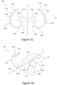
Figure 1C is a front view of the nasal dilator device ofFigure 1A ; -
Figure 1D is a rear perspective view of the nasal dilator device ofFigure 1A ; -
Figure 1E is a partial side view of the nasal dilator device ofFigure 1A ; -
Figure 2 is a front perspective view of a nasal dilator device including fin-like structures disposed thereon, according to some embodiments; -
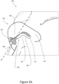
Figure 3A is a perspective view of a user donning the nasal dilator device ofFigures 1A to 1E ; -
Figure 3B is a side view of the user ofFigure 3A ; -
Figure 4A is a rear perspective view of a nasal dilator device according to some embodiments; -
Figure 4B is a front perspective view of the nasal dilator device ofFigure 4A ; -
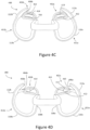
Figure 4C is a front view of the nasal dilator device ofFigure 4A in a closed configuration; -
Figure 4D is a front view of the nasal dilator device ofFigure 4A in a partially closed configuration; -
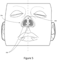
Figure 5 is a front perspective view of a user donning the nasal dilator device ofFigures 4A to 4D ; -
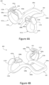
Figure 6A is a front view of a nasal dilator device in a partially closed configuration, wherein the nasal dilator device includes a capsule, according to some embodiments; -
Figure 6B is a front view of a nasal dilator device ofFigure 6A in a closed configuration; -
Figure 7A is a front view of a nasal dilator device including a film according to some embodiments; -
Figure 7B is a front perspective view of the nasal dilator device ofFigure 7A ; -
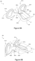
Figure 8A is a front perspective view of a nasal dilator device according to some embodiments not forming part of the invention and are provided for illustration purposes only; -
Figure 8B is a further front perspective view of the nasal dilator device ofFigure 8A ; -
Figure 8C is a top view of the nasal dilator device ofFigure 8A ; -
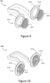
Figure 9 is a rear perspective view of a nasal dilator device with an attachable filter, according to some embodiments not forming part of the invention and are provided for illustration purposes only; and -
Figure 10 is a rear perspective view of a nasal dilator device including a filter, according to some embodiments not forming part of the invention and are provided for illustration purposes only. - Described embodiments generally relate to nasal dilator devices for facilitating respiration. Some embodiments relate to nasal dilator devices to be fitted to the nose to facilitate or improve respiration during sleeping and/or sporting activities and/or for general day-to-day wear. Some embodiments relate to nasal dilator devices including filtration mechanisms to filter airflow during respiration and other embodiments relate to nasal dilator devices including agent delivery mechanisms for delivery of fragrances and/medicaments to the nose during respiration.
- Referring to
Figure 1A to 1E , there is illustrated a nasal dilator device, generally indicated at 100 and substantially symmetrical about a longitudinal axis L, according to some embodiments. Thenasal dilator device 100 comprises a generallyU-shaped body 102 having acentral portion 104 and first and second leg members, 106a and 106b, respectively, extending from thecentral portion 104 in a first plane P1. - The nasal dilator device comprises a first
intermediate section 108a extending from anend 107a of thefirst leg member 106a and a secondintermediate section 108b extending from anend 107b of thesecond leg member 106b. As depicted inFigures 1A to 1E , the first and secondintermediate portions intermediate portions intermediate portions second ends intermediate sections - Referring again to
Figures 1A to 1E , thenasal dilator device 100 comprises afirst rib member 110a projecting from the firstintermediate section 108a in a second plane P2 and asecond rib member 110b projecting from the secondintermediate section 108b in a third plane P3. In some embodiments, the first andsecond rib members U-shaped body 102. The first andsecond rib members intermediate sections second rib members arcuate rib members cantilever rib members - In some embodiments, the first and
second rib members second rib members - The first and
second rib members intermediate sections second rib members Figures 3A and3B . As best depicted inFigures 1A and 1B , the firstintermediate section 108a may extend or transition between the first plane P1 and the second plane P2 to interconnect theend 107a of thefirst leg member 106a to aproximal end 109a of thefirst rib member 110a and the secondintermediate section 108b may extend or transition between the first plane and the third plane to interconnect theend 107b of thesecond leg member 106b to aproximal end 109b of thesecond rib member 110b. - In some embodiments, the configuration of the first and second
intermediate sections second rib members U-shaped body 104. For example, the configuration of the first and secondintermediate sections intermediate sections 108a 108b take the form of obtuse arcuate sections. In some embodiments, the first, second and third planes, P1, P2, P3 may be different from each other and in some embodiments, the second and third planes, P2, P3 may be the same plane and may be different to the first plane P1. - The first and second
intermediate sections second rib members - As depicted in
Figures 1A to 1E , the first andsecond rib members nasal dilator device 100 may comprise respective first and second nostril engaging elements, 112a and 112b, disposed atdistal ends arcuate rib members large surface areas arcuate rib members - In some embodiments, the first and second
nostril engaging elements pads pads major surface areas arcuate rib members - Referring now to
Figure 2 , there is illustrated a nasal dilator device, generally indicated at 200, according to some embodiments. Thenasal dilator device 200 may comprise similar components and elements to those ofnasal dilator device 100 depicted inFigures 1A to 1E and accordingly those similar components and elements are denoted like numerals. - In some embodiments, as depicted in
Figure 2 , thepads nasal dilator device 200 may be composed of a relatively soft overmould material, for example a polymer material such as thermoplastic elastomer (TPE) and/or may be provided with a series of protrusions, fins or fin-like structures 220 to provide a comfortable and/or grippable surface for engaging with the inner walls of the nostrils. In some embodiments, such an overmould material may be provided on at least a portion of therib members 110a, 110, and/or on at least a portion of theintermediate sections - The
nasal dilator device nostril engaging elements nasal passage 308, as discussed in more detail with reference toFigures 3A and3B below. -
Figure 3A is a perspective view of a user, generally indicated at 300, wearing or donning thenasal dilator device 100 ofFigure 1A andFigure 3B is a cross sectional view taken along a midline A-A of the nose of the user ofFigure 3A . - As depicted in
Figures 3A and3B , thenasal dilator device 100 is configured to be orientated such that thecentral portion 104 spans aseptum 302, and in particular, a columella 310 (the terminal section or fleshy external end of the septum) of anose 304 and is positioned toward atip 306 of thenose 304 and the first andsecond leg members nasal passage 308. For example, the first andsecond leg members nose 304. The first and secondintermediate sections septum 302 behind thecolumella 310 and thefibrofatty tissue 305 or bulbous region around the base of thenostrils 314 and the first andsecond rib members floor 312 of thenasal passage 308 behind thecolumella 310 and thefibrofatty tissue 305 or bulbous region around the base of thenostrils 314 to an inner wall (not shown) of thenostrils 314. In this way, thenasal dilator device 100 may be securely retained within thenose 304 with little or no pinching of or pressure being exerted on theseptum 302. Furthermore, the ergonomic shape of theintermediate portions columellas 310. - In some embodiments, the first and
second rib members nasal dilator device 100 are composed of a flexible material and are generally squeezed or compressed by a user into a compressed state to allow insertion into thenasal passages 308 of thenose 304. The first andsecond rib members nasal passage 308, the first andsecond rib members nostril 314 and on thefloor 312 of thenose 304, to thereby dilate thenasal passage 308. Thus, as opposed to exerting pressure on theseptum 302 to dilate thenasal passage 308, theintermediate portions nasal dilator device 100 are effective to cause the first andsecond rib members floor 312 of thenose 304 as a support structure for dilation of thenostrils 314. By using thefloor 312 of thenose 304 as a support structure or anchor from which the first andsecond rib members - The
nasal dilator device 100 is configured to cooperate with internal contours of thenose 304 and sit securely and comfortably in the nose, whilst mitigating obstruction of air flow through thenasal passage 308. For example, therib members nose 304 and provide a more comfortable fit. The first andsecond leg members second leg members central portion 104 in order to accommodate thecolumella 310 and to assist in holding thenasal dilator device 100 in place when worn. - Referring now to
Figures 4A to 4D , there is illustrated a nasal dilator device, generally indicated at 400, according to some embodiments. Thenasal dilator device 400 may comprise similar components and elements to those ofnasal dilator device 100 depicted inFigures 1A to 1E and accordingly those similar components and elements are denoted like numerals. - In addition to those similar components and elements of
nasal dilator device 100,nasal dilator device 400 may comprise a first and secondreleasable attachment mechanism releasable attachment mechanism U-shaped body 102, to thereby define first and second adjustable looped structures, 411a, and 411b, respectively. - In some embodiments, the first and second
releasable attachment mechanisms respective arms inner surfaces nostril engaging elements releasable attachment mechanisms respective sockets respective arms releasable attachment mechanisms second rib members U-shaped body 102. - For example, and as best illustrated in
Figures 4C and 4D , thearms protrusions 410 arranged to engage with at least one of or a series of grooves orridges 412 provided on or within thesockets ridges 412 may extend downwardly from aupper jaw portion 414 of thesockets lower jaw portion 416. - Application of sufficient force by a user to the first and second
releasable attachment mechanisms arms sockets detents 410 and thegrooves 412 to allow thedetents 410 and/or thegrooves 412 to deform and the degree or level of dilation to be adjusted. The engagement of thedetents 410 with thegrooves 412 may provide a sufficient restrictive force to hold thearms nose 304, as depicted inFigure 5 . - The
arms stoppers 414 at their ends to prevent or hinder thearms respective sockets arms sockets stoppers 414 may be arrow shaped. - In some embodiments, the
sockets intermediate sections respective arms releasable attachment mechanisms nostril engaging elements intermediate sections - In other embodiments, the
sockets second leg members respective arms releasable attachment mechanisms nostril engaging elements second leg members - In other embodiments, the
sockets second rib members respective arms attachment mechanisms nostril engaging elements second rib members - In other embodiments, the first and second
releasable attachment mechanisms respective sockets inner surfaces nostril engaging elements respective arms intermediate sections second leg members second rib members - As illustrated in
Figure 4C , thearms respective sockets nasal dilator device 400 to adopt or assume a fully closed or substantially fully closed state, to thereby tighten or contract the loopedstructures - As illustrated in
Figure 4D , thearms sockets nasal dilator device 400 to adopt or assume a partially closed state, to provide for looser or less tight loopedstructures - Referring to
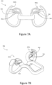
Figures 6A and 6B , there is depicted anasal dilator device 600 according to some embodiments. Thenasal dilator device 600 may comprise similar components and elements to those ofnasal dilator device 400 depicted inFigures 4A to 4D and accordingly those similar components and elements are denoted like numerals. - The
nasal dilator device 600 comprises at least onecapsule 602 disposed withinrespective sockets capsule 602 may include an agent such as a medicament and/or a fragrance or aromatic agent. As depicted inFigure 6B , thearms capsules 602 to release the agent, medicament and/or fragrance or aromatic agent when inserted into thesockets capsule 602 is activated, pierced or burst, thereby increasing a longevity or "shelf-life" and/or protecting the integrity of the medicament and/or aromatic agent. For example, the agent may be an aromatic scent such as an essential oil blend or synthetic fragrance blend to provide an olfactory and/or physiological response such as decongesting the nasal passages 318, promoting relaxation, promoting sleepiness, suppressing appetite or a medicament such as a drug to reduce pain such as a migraine. - Referring to
Figures 7A and 7B , there is depicted thenasal dilator device 700 according to some embodiments. Thenasal dilator device 700 may comprise similar components and elements to those ofnasal dilator device 400 depicted inFigures 4A to 4D and accordingly those similar components and elements are denoted like numerals. Thenasal dilator device 700 comprises at least one coating orfilm 702 arranged to release a fragrance, aroma or medicament. In some embodiments, thefilm 702 is arranged to release a fragrance, aroma or medicament in response to abrasion, such as scratching, scraping. Thefilm 702 may be provided with an outer cover, seal orstrip 704 to protect thefilm 702 from unintended abrasion, as depicted inFigures 7A and 7B at two separate stages of removal from thenasal dilator device 400. - In other embodiments, the coating or
film 700 may be arranged to release a fragrance, aroma or medicament in response to the removal or peeling off of the outer cover, strip orseal 704. In some embodiments, a fragrance, aroma or medicament may be provided or retained between two strips orfilms 702 forming a blister. - The coating or
film 702 may be comprise a polymer or a fibre. The coating orfilm 702 may be in the form of a "scratch and sniff" technology or peel off technology. - In some embodiments, as depicted in
Figures 7A and 7B , the coating orfilm 702 may be disposed on a surface of at least one of theattachment mechanisms structures film 702 may be disposed on thecentral portion 102, the first andsecond leg members intermediate sections rib members nostril engaging elements - In some embodiments, an aperture (not shown) is disposed in each of the first and second nostril engaging elements and is arranged to receive an agent, a compound, a medicament, a capsule, and/or a housing or compact arranged to receive an agent, medicament and/or a fragrance or aromatic agent. The agent may be absorbed by the inner walls of the nostrils transdermally and/or may be absorbed by mucosa in the
nostrils 314. - The following embodiments and examples referring to
Figures 8A, 8B ,8C ,9 and 10 are not according to the invention and are present for illustration purposes only. - Referring to
Figures 8A and 8B , there is depicted a nasal dilator device, generally indicated at 800 and substantially symmetrical about a longitudinal axis L, according to some embodiments. Thenasal dilator device 800 may comprise a generallyU-shaped body 802 having acentral portion 804 and first and second leg members, 806a and 806b, respectively, extending from thecentral portion 804 in a first plane P1. - The
nasal dilator device 800 comprises a firstintermediate section 808a extending from anend 807a of thefirst leg member 806a and a secondintermediate section 808b extending from anend 807b of thesecond leg member 806b. As depicted inFigures 8A and 8B , the first and secondintermediate portions intermediate portions intermediate portions second ends - As depicted in
Figures 8A to 8C , thenasal dilator device 800 comprises afirst loop structure 811a projecting from the firstintermediate section 808a in a second plane P2 and asecond loop structure 811b projecting from the secondintermediate section 808b in a third plane P3. In some embodiments, the first andsecond loop structures U-shaped body 802 and away from one another. In some embodiments, the loopedstructure - In some embodiments, the first
intermediate section 808a may extend or transition between the first plane P1 and the second plane P2 to interconnect theend 807a of thefirst leg member 806a to aproximal end 809a of thefirst loop structure 811b and the secondintermediate section 808b may extend or transition between the first plane P1 and the third plane P3 to interconnect theend 807b of thesecond leg member 806b to a proximal end 809b of thesecond loop structure 811b. - In some embodiments, the configuration of the first and second
intermediate sections second loop structures U-shaped body 804. For example, the configuration of the first and secondintermediate sections intermediate sections 108a 108b take the form of obtuse arcuate sections. In some embodiments, the first, second and third planes, P1, P2, P3 may be different from each other and in some embodiments, the second and third planes, P2, P3 may be the same plane and may be different to the first plane P1. - The first and
second leg members second leg members central portion 804 in order to accommodate thecolumella 310 and to assist in holding thenasal dilator device 800 in place when worn. - The first and second
intermediate sections second loop structures - In some embodiments, the first and second looped
structures flanged portions structures flanged portions structures - Referring to
Figure 9 , there is depicted thenasal dilator device 900 according to some embodiments. Thenasal dilator device 900 may comprise similar components and elements to those ofnasal dilator device 800 depicted inFigures 8A to 8C and accordingly those similar components and elements are denoted like numerals. - The first and
second loop structures nasal dilator device 900 may be each arranged to receive afilter filters second loop structures - The
filters filters - In some embodiments, as depicted in
Figure 9 , thefilters second loop structures filters second loop structures - Referring to
Figure 10 , there is depicted thenasal dilator device 1000 according to some embodiments. Thenasal dilator device 1000 may comprise similar components and elements to those ofnasal dilator device 800 depicted inFigures 8A to 8C and accordingly those similar components and elements are denoted like numerals. - The
filters nasal dilator device 1000 may be fixed to the first andsecond loop structures filters structures second loop structures - In some embodiments, the
nasal dilator device - In some embodiments, the
nasal dilator devices nasal dilator device central portion - The
U-shaped body intermediate sections rib members structure U-shaped body 102 and/or theintermediate sections rib members U-shaped body 102 and/or theintermediate sections rib members rib members U-shaped body 102 and/or theintermediate sections rib members - In some embodiments, an overall width of the
nasal dilator device central portion leg members intermediate sections rib members nasal dilator device leg members nasal dilator device leg members nasal dilator device leg members - It will be appreciated by persons skilled in the art that numerous variations and/or modifications may be made to the above-described embodiments,. The present embodiments are, therefore, to be considered in all respects as illustrative and not restrictive.
Claims (14)
- A nasal dilator device (100, 200, 300, 400, 500, 600, 700) comprising:
a substantially U-shaped body (102) including:a central portion (104) arranged to span a septum (302) of a nose (304) when worn by a user; and
first and second leg members (106a, 106b) extending from the central portion in a first plane (P1);a first cantilever rib member (110a) extending outward from the U-shaped body in a second plane (P2);a second cantilever rib member (110b) extending outward from the U-shaped body in a third plane (P3);wherein the first and second cantilever rib members (110a, 110b) extend away from each other;a first intermediate section (108a) connecting an end (107a) of the first leg member to a proximal end (109a) of the first cantilever rib member, wherein the first intermediate section extends between the first plane and second plane; anda second intermediate section (108b) connecting an end (107b) of the second leg member to a proximal end (109b) of the second cantilever rib member, wherein the second intermediate section extends between the first plane and the third plane;wherein the first, second and third planes are different from each other, or wherein the second and third planes are the same plane and are different to the first plane, or wherein the second and third planes are converging;wherein the first and second intermediate sections are arcuate intermediate sections, each having a curvature along its length;and wherein:the first and second leg members (106a, 106b) are inclined towards each other such that a relatively greater distance is provided between the first and second leg members towards the central portion to accommodate a columella (310) of a nose (304) when donned by the user;the first and second intermediate sections (108a, 108b) are inclined away from each other to assist in urging the respective first and second cantilever rib members (110a, 110b) against inner walls of respective nostrils when the device is worn by the user;the first and second intermediate sections (108a, 108b) extend obtusely from the ends of the first and second leg members (106a, 106b), and wherein each of the second and third planes (P2, P3) forms an obtuse angle with the first plane (P1);and wherein the first and second intermediate sections, in use, extend along a length of the septum and each of the first and second cantilever rib members, in use, extends from a floor (312) of a respective nasal passage (308) to an inner wall of the nostrils (314). - The nasal dilator device of claim 1, wherein in use the first and second intermediate sections (108a, 108b) extend along a length of the septum (302) behind the columella (310) and the fibrofatty tissue (305) or bulbous region around the base of the nostrils (314), and the first and second cantilever rib members (110a, 110b) each extend from a floor (312) of the nasal passage (308) behind the columella (310) and the fibrofatty tissue (305) or bulbous region around the base of the nostrils (314) to an inner wall of the nostrils.
- The nasal dilator device of claim 1 or claim 2, wherein in use the intermediate portions (108a, 108b) of said nasal dilator device cause the first and second cantilever rib members (110a, 110b) to use the floor (312) of the nose (304) as a support structure for dilation of the nostrils (314); preferably wherein in use the first and second cantilever rib members (110a, 110b) each exerts an outward force on the inner wall of the nostril (314) and on the floor (312) of the nose (304) to thereby dilate the nasal passage (308) of the nose (304).
- The nasal dilator device of any preceding claim, wherein the first and second cantilever rib members (110a, 110b) are arcuate cantilever rib members, each having a curvature along its length; and preferably exhibit an elongate arched profile which approximates at least a portion of one of a circle, ellipse or parabola; preferably the first and second cantilever rib members (110a, 110b) are curved or arcuate along their length to correspond with the internal contours of the nose (304).
- The nasal dilator device of any preceding claim, wherein the second and third planes are converging planes each forms an obtuse angle of 95° to 130° with the first plane such that the first and second intermediate sections (108a 108b) are obtuse arcuate sections; or wherein said nasal device is substantially symmetrical about a longitudinal axis (L) and the first and second intermediate sections (108a, 108b) extend from the first and second ends (107a, 107b) substantially at an angle between 95 degrees and 130 degrees to the longitudinal axis (L).
- The nasal dilator device of any preceding claim, wherein the first and second cantilever rib members (110a, 110b) comprise respective first and second nostril engaging elements (112a, 112b) for engaging with an inner wall of a respective nostril; preferably wherein the first and second nostril engaging elements are disposed at distal ends (114a, 114b) of the first and second cantilever rib members, respectively; further preferably enlarged pads (118a, 118b) are disposed on the first and second nostril engaging elements to engage with inner walls of the nostrils; and further preferably wherein in use said device is configured to be orientated in the nose such that the first and second nostril engaging elements (112a, 112b) are positioned at a junction of the greater alar cartilage and lateral nasal cartilage.
- The nasal dilator device of any preceding claim, further comprising a first and second releasable attachment mechanism (402a, 402b) for releasably attaching the first and second cantilever rib members (110a, 110b), respectively, to the U-shaped body (102).
- The nasal dilator device of claim 6, comprising a first and second releasable attachment mechanism (402a, 402b) for releasably attaching the first and second cantilever rib members (110a, 110b), respectively, to the U-shaped body (102), and wherein the releasable attachment mechanisms are arranged to releasably attach the first and second nostril engaging elements (112a, 112b) to the first and second leg members (106a, 106b), respectively; or wherein the releasable attachment mechanisms are arranged to releasably attach the first and second nostril engaging elements to the first and second intermediate sections (108a, 108b), respectively.
- The nasal dilator device of claim 7 or claim 8, wherein the releasable attachment mechanisms (402a, 402b) each comprise an arm (404a, 404b) and a socket (408a, 408b) arranged to receive and engage the arm; preferably wherein a stopper (414) is disposed at an end of the arm to hinder the arm from withdrawing from the socket.
- The nasal dilator device of claim 9, wherein the arms (404a, 404b) are disposed on an inner surface (406a, 406b) of first and second nostril engaging elements (112a, 112b) of the first and second cantilever rib members (110a, 110b), respectively, and the sockets are disposed on the first and second leg members (106a, 106b) or on the first and second intermediate sections (108a, 108b).
- The nasal dilator device of claim 9, wherein the sockets (408a, 408b) are disposed on an inner surface (406a, 406b) of first and second nostril engaging elements (112a, 112b) of the first and second cantilever rib members (110a, 110b), respectively, and the arms (404a, 404b) are disposed on the first and second leg members (106a, 106b) or on first and second intermediate sections (108a, 108b).
- The nasal dilator device of any one of claims 7 to 11, wherein the first and second releasable attachment mechanisms (402a, 402b) are configured to allow a user to selectively adjust a degree of dilation or expansion and contraction of the first and second cantilever rib members (110a, 110b) with respect to the U-shaped body (102).
- The nasal dilator device of any preceding claim, wherein the first and second cantilever rib members (110a, 110b) of the nasal dilator device (100) are composed of a flexible material and are generally squeezed or compressed by a user into a compressed state to allow insertion into the nasal passages (308) of the nose (304); preferably, wherein the first and second cantilever rib members (110a, 110b) are biased to reform or revert to their an uncompressed state and once inserted into the nasal passage (308).
- The nasal dilator device of any preceding claim wherein:(A) said device further comprising:(i) a film (702) disposed on a surface of the nasal dilator and a removable seal (704) provided on the film to mitigate release of a compound from the film; and/or(ii) an overmould disposed on at least one of the central portion (104), the leg members (106a, 106b), the intermediate sections (108a, 108b) and the arcuate cantilever rib members (110a, 110b), preferably wherein the overmould is infused with a compound, further preferably the overmould is infused with a medicament, a fragrance or an aroma; and/or(B) wherein the central portion (104) comprises a tab extending in a direction substantially opposite to the first and second leg members (106a, 106b) to assist with insertion, removal and/or placement of the nasal dilator device; preferably wherein the tab is removeable from the nasal dilator device.
Applications Claiming Priority (1)
| Application Number | Priority Date | Filing Date | Title |
|---|---|---|---|
| PCT/AU2014/000649 WO2015192162A1 (en) | 2014-06-20 | 2014-06-20 | Nasal dilator devices |
Publications (4)
| Publication Number | Publication Date |
|---|---|
| EP3157475A1 EP3157475A1 (en) | 2017-04-26 |
| EP3157475A4 EP3157475A4 (en) | 2018-04-18 |
| EP3157475B1 true EP3157475B1 (en) | 2025-03-12 |
| EP3157475C0 EP3157475C0 (en) | 2025-03-12 |
Family
ID=54934559
Family Applications (2)
| Application Number | Title | Priority Date | Filing Date |
|---|---|---|---|
| EP14895038.9A Active EP3157475B1 (en) | 2014-06-20 | 2014-06-20 | Nasal dilator devices |
| EP15809245.2A Pending EP3157476A4 (en) | 2014-06-20 | 2015-01-30 | Nasal dilator devices |
Family Applications After (1)
| Application Number | Title | Priority Date | Filing Date |
|---|---|---|---|
| EP15809245.2A Pending EP3157476A4 (en) | 2014-06-20 | 2015-01-30 | Nasal dilator devices |
Country Status (14)
| Country | Link |
|---|---|
| US (6) | US11712361B2 (en) |
| EP (2) | EP3157475B1 (en) |
| JP (2) | JP6537535B2 (en) |
| KR (2) | KR102313500B1 (en) |
| CN (2) | CN106572917B (en) |
| AU (2) | AU2014398172B2 (en) |
| BR (2) | BR112016029675B1 (en) |
| CA (2) | CA2952261C (en) |
| ES (1) | ES3026057T3 (en) |
| MY (1) | MY188121A (en) |
| NZ (1) | NZ629495A (en) |
| RU (2) | RU2668464C2 (en) |
| TW (2) | TWI698233B (en) |
| WO (2) | WO2015192162A1 (en) |
Families Citing this family (37)
| Publication number | Priority date | Publication date | Assignee | Title |
|---|---|---|---|---|
| KR102313500B1 (en) * | 2014-06-20 | 2021-10-15 | 에이에스에이피 브리드어시씨스트 피티와이 엘티디 | Nasal dilator devices |
| JP6656227B2 (en) | 2014-08-26 | 2020-03-04 | スピロックス, インク.Spirox, Inc. | Nasal implants, use systems and methods of use |
| AU2016326676B2 (en) | 2015-09-25 | 2021-07-08 | Stryker Corporation | Nasal implants and systems and method of use |
| USD819205S1 (en) * | 2016-05-05 | 2018-05-29 | Tru-Breathe, Inc. | Nasal dilator |
| USD868248S1 (en) * | 2016-05-05 | 2019-11-26 | Tru-Breathe, Inc. | Nasal dilator |
| CN108348350B (en) * | 2016-06-01 | 2020-08-04 | 王雷 | a nasal dilator |
| WO2018125868A1 (en) * | 2016-12-30 | 2018-07-05 | Spirox, Inc. | Nasal implants and methods of use |
| JP7173986B2 (en) | 2017-04-13 | 2022-11-17 | スピロックス,インク. | Nasal implants, delivery tools, systems, and methods of use |
| CN107928854B (en) * | 2017-11-13 | 2024-01-05 | 深圳市福生医疗器械有限公司 | Small column retention clip for cracked lips |
| GB2576007B (en) * | 2018-07-31 | 2022-04-20 | Minks Wendy | A nose clamp |
| WO2020039095A1 (en) * | 2018-08-24 | 2020-02-27 | Nasal Medical Limited | Nasal apparatus and method of drug delivery using said nasal apparatus |
| WO2020044271A2 (en) * | 2018-08-30 | 2020-03-05 | Bti Therapeutics, Inc | A delivery system for dispensing oils |
| US10413686B2 (en) * | 2018-10-22 | 2019-09-17 | Clifford S. Aboff | Columella nasal clip / dilator for aromatic substances |
| USD889647S1 (en) * | 2018-11-05 | 2020-07-07 | Thomas D. Smith | Nasal insert |
| TWI673076B (en) * | 2018-12-28 | 2019-10-01 | 蔡淑真 | Nasal inserter |
| EP4684822A3 (en) | 2019-01-25 | 2026-03-04 | ASAP Breatheassist Pty Ltd | Nasal devices |
| KR102007253B1 (en) * | 2019-04-12 | 2019-08-06 | 주식회사 에어랩 | Apparatus for preventing snoring |
| TWD206924S (en) * | 2019-06-13 | 2020-09-01 | 澳大利亞商Asap呼吸援助有限公司 | Nasal dilator device |
| CN110538393B (en) * | 2019-08-07 | 2021-06-15 | 焦作大学 | A nose-plugged professional long-distance running dustproof device |
| WO2021041228A1 (en) * | 2019-08-23 | 2021-03-04 | Garcia Rojas Alejandro | Nasal dilator apparatus |
| KR20210156629A (en) | 2020-06-18 | 2021-12-27 | 이해영 | Apparatus for inducing deep sleep |
| WO2022020877A1 (en) * | 2020-07-13 | 2022-02-03 | Asap Breatheassist Pty Ltd | Sample collection device, sample collection kit, sample collection system, diagnostic device, and associated methods |
| IT202000022144A1 (en) * | 2020-09-18 | 2022-03-18 | FKS Holding Srl | NASAL BALANCER DEVICE |
| KR102470587B1 (en) | 2020-12-22 | 2022-11-25 | 김영규 | Nasal cavity dilator |
| CN117279683A (en) * | 2021-04-29 | 2023-12-22 | 王雷 | A sustained-release device that slowly releases a compound within the nasal passage |
| ES2936757A1 (en) * | 2021-09-20 | 2023-03-21 | Diaz Gamez Valeriano | ACTIVABLE NASAL FILTER (Machine-translation by Google Translate, not legally binding) |
| GB2616634A (en) * | 2022-03-15 | 2023-09-20 | Aria Healthcare Ltd | Nasal dilator |
| US20240016650A1 (en) * | 2022-07-15 | 2024-01-18 | Aso Llc | External Nasal Dilator for Delivering Scent to the Nose |
| USD1077219S1 (en) | 2022-07-17 | 2025-05-27 | Aso Llc | Nasal dilator with arms |
| KR102688053B1 (en) | 2022-09-16 | 2024-07-23 | 이동훈 | Adjustable snoring prevention device |
| US12403032B2 (en) | 2023-10-11 | 2025-09-02 | Pei Yuan Wu | Nasal dilator |
| US20250161090A1 (en) * | 2023-11-20 | 2025-05-22 | Breathewave Technologies Inc. | Nasal dilator system |
| WO2025120376A1 (en) | 2023-12-04 | 2025-06-12 | Saeidi Fatemeh Sadat | Nose shaping and lifting mask |
| US20250255745A1 (en) * | 2024-02-13 | 2025-08-14 | Breathewave Technologies Inc. | Personalized-fit nasal dilator |
| TW202545488A (en) * | 2024-02-14 | 2025-12-01 | 歐德溫 博喬治 | Nasal dilator and method of manufacturing a nasal dilator |
| KR102734661B1 (en) | 2024-02-28 | 2024-11-26 | 성동연 | Variable nasal dilator |
| USD1117746S1 (en) | 2025-04-09 | 2026-03-10 | Job Santoyo | Insertable nasal device |
Citations (1)
| Publication number | Priority date | Publication date | Assignee | Title |
|---|---|---|---|---|
| US1481581A (en) * | 1922-10-18 | 1924-01-22 | Henry R Woodward | Nostril expander |
Family Cites Families (91)
| Publication number | Priority date | Publication date | Assignee | Title |
|---|---|---|---|---|
| US851048A (en) * | 1906-08-01 | 1907-04-23 | Henry R Woodward | Nostril-expander. |
| US1034566A (en) | 1911-01-14 | 1912-08-06 | Alfred Allen Barratt | Nostril-distending apparatus. |
| US1077574A (en) * | 1913-01-15 | 1913-11-04 | Henry R Woodward | Nostril-expander. |
| US1255578A (en) * | 1917-02-27 | 1918-02-05 | George Boxley | Nasal appliance. |
| US2243360A (en) * | 1938-12-30 | 1941-05-27 | Slatis Abraham | Filter or medicament casing |
| ES149951Y (en) | 1969-06-30 | 1970-06-01 | Ramos Caballero | DEVICE TO FACILITATE NASAL BREATHING. |
| US3722509A (en) | 1971-01-05 | 1973-03-27 | J Nebel | Nasal filters |
| US3905335A (en) | 1974-03-21 | 1975-09-16 | Gerald J Kapp | Nasal air filter |
| US4592357A (en) | 1981-05-21 | 1986-06-03 | Ersek Robert A | Septal splint |
| US4414977A (en) * | 1981-07-20 | 1983-11-15 | Wisconsin Alumni Research Foundation | Nasal dilator |
| US4576168A (en) | 1983-01-05 | 1986-03-18 | Jalowayski Alfredo A | Nasal dilator |
| SU1344315A1 (en) * | 1986-05-13 | 1987-10-15 | Севастопольская Детская Городская Больница | Dilator of inferior nasal passage |
| GB8627600D0 (en) * | 1986-11-19 | 1986-12-17 | Petruson B | Nasal device |
| US4759365A (en) | 1987-03-27 | 1988-07-26 | Leo Askinazy | Spring coil wire device |
| JPH04501212A (en) | 1987-05-29 | 1992-03-05 | ニュー・サウス・ウェールズ州 | medical test equipment |
| US5059193A (en) | 1989-11-20 | 1991-10-22 | Spine-Tech, Inc. | Expandable spinal implant and surgical method |
| JP3390431B2 (en) | 1991-02-22 | 2003-03-24 | マドハヴァン、ピシャロディ | Centrally expandable disc implant and method |
| NZ242881A (en) * | 1991-06-10 | 1994-11-25 | Creative Integration & Design | Nasal dilator: flexible strip attached across front of nose |
| JPH0633938Y2 (en) * | 1991-11-25 | 1994-09-07 | 弥栄子 朝岡 | Nasal congestion prevention tool |
| US5423858A (en) | 1993-09-30 | 1995-06-13 | United States Surgical Corporation | Septoplasty fasteners and device for applying same |
| AUPM765994A0 (en) | 1994-08-26 | 1994-09-15 | University Of Sydney, The | Nasal filters |
| AUPM765894A0 (en) | 1994-08-26 | 1994-09-15 | University Of Sydney, The | Particle detection and identification |
| US5683465A (en) | 1996-03-18 | 1997-11-04 | Shinn; Gary Lee | Artificial intervertebral disk prosthesis |
| FR2753368B1 (en) | 1996-09-13 | 1999-01-08 | Chauvin Jean Luc | EXPANSIONAL OSTEOSYNTHESIS CAGE |
| US5931852A (en) * | 1997-06-04 | 1999-08-03 | Brennan; H. George | Nose airway device |
| US5895409A (en) | 1997-09-16 | 1999-04-20 | Mehdizadeh; Hamid | Nasal dilator |
| JPH11192251A (en) | 1997-12-29 | 1999-07-21 | Hidetoshi Araki | Preventive method and preventive device of snore |
| AUPP131098A0 (en) | 1998-01-13 | 1998-02-05 | Bellon Pty Limited | Identification of particles and macromolecular species |
| US6270512B1 (en) | 1998-01-22 | 2001-08-07 | Jean V Rittmann | Internal nasal dilator |
| BR9805340B1 (en) | 1998-12-14 | 2009-01-13 | variable expansion insert for spinal stabilization. | |
| AUPQ582100A0 (en) | 2000-02-24 | 2000-03-16 | Irm Technologies Pty Ltd | Nasal filter and sampler |
| US6821298B1 (en) | 2000-04-18 | 2004-11-23 | Roger P. Jackson | Anterior expandable spinal fusion cage system |
| US6561188B1 (en) | 2000-08-21 | 2003-05-13 | Ellis Alan D | Nasal breathing apparatus and methods |
| US6626179B1 (en) | 2000-09-29 | 2003-09-30 | Philip Pedley | Breathing valve for improving oxygen absorption |
| WO2002031465A1 (en) | 2000-10-13 | 2002-04-18 | Inhalix Pty Ltd | Collection of particles to be analysed by assay systems |
| AUPR271901A0 (en) | 2001-01-25 | 2001-02-22 | Inhalix Pty Ltd | Collection and analysis of particles |
| US6562057B2 (en) | 2001-05-22 | 2003-05-13 | Ernest Santin | Nasal breathing assist devices |
| US8403954B2 (en) | 2001-05-22 | 2013-03-26 | Sanostec Corp. | Nasal congestion, obstruction relief, and drug delivery |
| US7390331B2 (en) | 2001-05-22 | 2008-06-24 | Sanostec Corp | Nasal inserts |
| US20030086825A1 (en) * | 2001-11-02 | 2003-05-08 | Brennan H. George | Nose airway device for detecting airborne contaminants |
| US6863066B2 (en) | 2002-01-28 | 2005-03-08 | Ronald Jack Ogle | Adjustable nasal dilator filter |
| WO2004026391A1 (en) * | 2002-09-18 | 2004-04-01 | Asap Breathe Assist Pty Ltd | A nasal cavity dilator |
| US20140246023A1 (en) * | 2006-02-28 | 2014-09-04 | Paz Maryanka | Nasal cavity dilator device |
| US7108198B2 (en) * | 2002-10-25 | 2006-09-19 | Altadonna Jr James | Nasal aromatherapy dispenser clip |
| ES1053382Y (en) * | 2002-12-09 | 2003-07-16 | Ruiz Jose Francisco Padilla | DILATATING PROTECTION OF THE NASAL VESTIBLE. |
| US7156098B2 (en) * | 2004-03-19 | 2007-01-02 | Dolezal Creative Innovations, Llc | Breathing air filtration system |
| US8833369B2 (en) | 2004-03-19 | 2014-09-16 | Airware, Inc. | Breathing air filtration devices |
| US7297162B2 (en) | 2004-06-09 | 2007-11-20 | Zimmer Spine, Inc. | Expandable helical cage |
| AU2004100927B4 (en) * | 2004-11-01 | 2005-03-24 | Richard Benson | Snorenomore (anti-snoring device) |
| US8491622B2 (en) * | 2005-02-24 | 2013-07-23 | Thomas Brown | Multi-layer internal nasal dilator with tubular expanders and compound delivery protrusions |
| US7055523B1 (en) * | 2005-02-24 | 2006-06-06 | Brown Thomas W | Internal nasal dilator and delivery mechanism |
| US6978781B1 (en) | 2005-03-11 | 2005-12-27 | John Jordan | Nasal dilator |
| US6971388B1 (en) * | 2005-03-21 | 2005-12-06 | Santa Barbara Medco, Inc. | Internal nasal dilator filter |
| US20060266367A1 (en) * | 2005-05-27 | 2006-11-30 | Alisa Noce | Nasal dilator |
| JP3787636B1 (en) | 2005-08-26 | 2006-06-21 | 国立大学法人 岡山大学 | Nostril plug for improving articulation disorder |
| FR2890567B1 (en) | 2005-09-13 | 2008-05-30 | Centre Nat Rech Scient | PER-OPERATIVE DETECTION HEAD COUPLED TO AN EXERSE TOOL |
| US20070107731A1 (en) * | 2005-11-15 | 2007-05-17 | Reed Glen B | Clip-in nostril expander |
| GB0607533D0 (en) | 2006-04-13 | 2006-05-24 | James Lawrence C W | Apparatus for assisting breathing through a persons nose |
| USD652143S1 (en) * | 2006-05-22 | 2012-01-10 | Thomas Brown | Multi-layer internal nasal dilator with tubular expanders and compound delivery protrusions |
| GB0610171D0 (en) | 2006-05-23 | 2006-06-28 | Robitaille Jean Pierre | Valved nasal canula |
| RU2009111263A (en) * | 2006-08-30 | 2010-10-10 | Дэвид Уилльям СМИТ (US) | METHOD FOR GIVING ONE-AXIS OR MULTI-AXIS RIGIDITY TO EXTRUDED MATERIALS, AND ALSO PRODUCTS PRODUCED FROM THEM |
| CN101534755A (en) | 2006-11-16 | 2009-09-16 | 科里·C·穆尔 | Nasal cavity dilating device |
| US7563271B2 (en) * | 2007-01-04 | 2009-07-21 | Howard Laurence E | Breathing aid device that decreases incidence of snoring |
| US20080178873A1 (en) | 2007-01-25 | 2008-07-31 | Alpers Adam L | Device for prevention of snoring |
| WO2008092198A1 (en) | 2007-01-31 | 2008-08-07 | Euan Roger Tovey | A collection device for sampling exhaled airstreams |
| US8641852B2 (en) * | 2007-02-06 | 2014-02-04 | Corbett Lair Inc. | Nasal dilator and methods of fabricating medical devices |
| USD575397S1 (en) * | 2007-02-08 | 2008-08-19 | Alisa A. Noce | Nasal dilator |
| TW200836781A (en) | 2007-03-07 | 2008-09-16 | Ventus Medical Inc | Nasal devices |
| US8834512B1 (en) * | 2007-12-12 | 2014-09-16 | International Patent Development Group, Llc | Nasal dilator comprising joined legs with end pads and air passages |
| US20090198268A1 (en) | 2008-02-01 | 2009-08-06 | Ernest Jerold Case | Nasal dilation apparatus |
| WO2009124567A1 (en) | 2008-04-11 | 2009-10-15 | Adactive Marketing Ab | Nose-dilating device with recess |
| US20100042134A1 (en) | 2008-04-18 | 2010-02-18 | Abraham Wien | Nostril dilator |
| KR100893945B1 (en) | 2008-09-10 | 2009-04-22 | 민경일 | Snoring Mechanism |
| IT1398484B1 (en) | 2010-02-24 | 2013-03-01 | Mistro | NASAL ANATOMIC DILATOR. |
| ES2343350B1 (en) | 2010-05-17 | 2011-06-15 | Yang, S.L. | "NASAL DE QUITA Y PON DEVICE". |
| SE535611C2 (en) * | 2010-06-24 | 2012-10-16 | Nose Option Ab | Näsplugg |
| US9604024B2 (en) | 2010-09-17 | 2017-03-28 | Salter Labs | Divided cannula with each nare communicating with each flow path |
| ITBO20110182A1 (en) * | 2011-04-07 | 2012-10-08 | Gaetano Libra | DEVICE FOR RESTRICTING THE COLUMELLA AND TO DILUTE THE NASAL VALVE |
| WO2012151095A1 (en) | 2011-05-04 | 2012-11-08 | First Defense Holdings Llc | Nasal filter structure |
| US20130144325A1 (en) * | 2011-06-02 | 2013-06-06 | Ludwig A. Allegra | Nasal dilator |
| WO2013046013A1 (en) | 2011-09-29 | 2013-04-04 | Trudell Medical International | Nasal insert and cannula and methods for the use thereof |
| AU2013205673A1 (en) * | 2012-07-27 | 2014-02-13 | Asap Breatheassist Pty Ltd | Improvements relating to devices for dilating the nostrils and/or releasing an agent within the nose |
| US20150314088A1 (en) * | 2012-07-27 | 2015-11-05 | Nicholas Jon Ede | Device for improving air flow through a nasal cavity during physical activity such as sporting pursuits |
| AU2013204827B2 (en) | 2012-07-27 | 2014-11-06 | Asap Breatheassist Pty Ltd | Improvements relating to nasal dilators |
| AU350709S (en) | 2013-01-21 | 2013-09-09 | Asap Breatheassist Pty Ltd | Nasal dilator device |
| RU131295U1 (en) * | 2013-03-18 | 2013-08-20 | Лев Михайлович Мнацаканов | DEVICE FOR IMPROVING NOSE RESPIRATION |
| WO2014183966A1 (en) | 2013-05-13 | 2014-11-20 | Anthonius Fredericus Maria Bende | Nasal dilator |
| US20150000675A1 (en) * | 2013-06-28 | 2015-01-01 | James Kallikounis | Nasal breathing aid |
| CN103520815B (en) | 2013-10-08 | 2015-10-07 | 魏永祥 | Positive end expiratory pressure nasal devices |
| KR102313500B1 (en) * | 2014-06-20 | 2021-10-15 | 에이에스에이피 브리드어시씨스트 피티와이 엘티디 | Nasal dilator devices |
| USD819205S1 (en) * | 2016-05-05 | 2018-05-29 | Tru-Breathe, Inc. | Nasal dilator |
-
2014
- 2014-06-20 KR KR1020177001614A patent/KR102313500B1/en active Active
- 2014-06-20 AU AU2014398172A patent/AU2014398172B2/en active Active
- 2014-06-20 RU RU2017101211A patent/RU2668464C2/en active
- 2014-06-20 ES ES14895038T patent/ES3026057T3/en active Active
- 2014-06-20 EP EP14895038.9A patent/EP3157475B1/en active Active
- 2014-06-20 CA CA2952261A patent/CA2952261C/en active Active
- 2014-06-20 US US15/319,940 patent/US11712361B2/en active Active
- 2014-06-20 BR BR112016029675-3A patent/BR112016029675B1/en active IP Right Grant
- 2014-06-20 CN CN201480080589.9A patent/CN106572917B/en active Active
- 2014-06-20 NZ NZ629495A patent/NZ629495A/en unknown
- 2014-06-20 JP JP2016574088A patent/JP6537535B2/en active Active
- 2014-06-20 WO PCT/AU2014/000649 patent/WO2015192162A1/en not_active Ceased
-
2015
- 2015-01-30 CN CN201580033229.8A patent/CN106470647B/en active Active
- 2015-01-30 WO PCT/AU2015/050032 patent/WO2015192173A1/en not_active Ceased
- 2015-01-30 MY MYPI2016704618A patent/MY188121A/en unknown
- 2015-01-30 AU AU2015278239A patent/AU2015278239B2/en active Active
- 2015-01-30 BR BR112016029914-0A patent/BR112016029914B1/en active IP Right Grant
- 2015-01-30 EP EP15809245.2A patent/EP3157476A4/en active Pending
- 2015-01-30 CA CA2952265A patent/CA2952265C/en active Active
- 2015-01-30 JP JP2016574177A patent/JP6626014B2/en active Active
- 2015-01-30 KR KR1020177001486A patent/KR102444472B1/en active Active
- 2015-01-30 RU RU2017100406A patent/RU2676429C2/en active
- 2015-01-30 US US15/319,941 patent/US11717432B2/en active Active
- 2015-06-18 TW TW104119734A patent/TWI698233B/en active
- 2015-06-18 TW TW104119729A patent/TWI698232B/en active
-
2023
- 2023-06-15 US US18/210,185 patent/US12544251B2/en active Active
- 2023-06-15 US US18/210,184 patent/US12485032B2/en active Active
-
2025
- 2025-11-07 US US19/382,718 patent/US20260060832A1/en active Pending
- 2025-11-26 US US19/402,039 patent/US20260076816A1/en active Pending
Patent Citations (1)
| Publication number | Priority date | Publication date | Assignee | Title |
|---|---|---|---|---|
| US1481581A (en) * | 1922-10-18 | 1924-01-22 | Henry R Woodward | Nostril expander |
Also Published As
Similar Documents
| Publication | Publication Date | Title |
|---|---|---|
| US12485032B2 (en) | Nasal dilator devices | |
| CA2986934C (en) | Nasal dilators | |
| HK1233483B (en) | Nasal dilator devices | |
| HK1233483A1 (en) | Nasal dilator devices | |
| NZ727784B2 (en) | Nasal dilator devices |
Legal Events
| Date | Code | Title | Description |
|---|---|---|---|
| STAA | Information on the status of an ep patent application or granted ep patent |
Free format text: STATUS: THE INTERNATIONAL PUBLICATION HAS BEEN MADE |
|
| PUAI | Public reference made under article 153(3) epc to a published international application that has entered the european phase |
Free format text: ORIGINAL CODE: 0009012 |
|
| STAA | Information on the status of an ep patent application or granted ep patent |
Free format text: STATUS: REQUEST FOR EXAMINATION WAS MADE |
|
| 17P | Request for examination filed |
Effective date: 20161208 |
|
| AK | Designated contracting states |
Kind code of ref document: A1 Designated state(s): AL AT BE BG CH CY CZ DE DK EE ES FI FR GB GR HR HU IE IS IT LI LT LU LV MC MK MT NL NO PL PT RO RS SE SI SK SM TR |
|
| AX | Request for extension of the european patent |
Extension state: BA ME |
|
| DAX | Request for extension of the european patent (deleted) | ||
| REG | Reference to a national code |
Ref country code: HK Ref legal event code: DE Ref document number: 1233483 Country of ref document: HK |
|
| A4 | Supplementary search report drawn up and despatched |
Effective date: 20180321 |
|
| RIC1 | Information provided on ipc code assigned before grant |
Ipc: A61F 5/56 20060101ALI20180315BHEP Ipc: A61F 5/08 20060101AFI20180315BHEP |
|
| STAA | Information on the status of an ep patent application or granted ep patent |
Free format text: STATUS: EXAMINATION IS IN PROGRESS |
|
| 17Q | First examination report despatched |
Effective date: 20200406 |
|
| RAP3 | Party data changed (applicant data changed or rights of an application transferred) |
Owner name: ASAP BREATHEASSIST PTY LTD |
|
| GRAP | Despatch of communication of intention to grant a patent |
Free format text: ORIGINAL CODE: EPIDOSNIGR1 |
|
| STAA | Information on the status of an ep patent application or granted ep patent |
Free format text: STATUS: GRANT OF PATENT IS INTENDED |
|
| INTG | Intention to grant announced |
Effective date: 20231207 |
|
| GRAJ | Information related to disapproval of communication of intention to grant by the applicant or resumption of examination proceedings by the epo deleted |
Free format text: ORIGINAL CODE: EPIDOSDIGR1 |
|
| STAA | Information on the status of an ep patent application or granted ep patent |
Free format text: STATUS: EXAMINATION IS IN PROGRESS |
|
| GRAP | Despatch of communication of intention to grant a patent |
Free format text: ORIGINAL CODE: EPIDOSNIGR1 |
|
| STAA | Information on the status of an ep patent application or granted ep patent |
Free format text: STATUS: GRANT OF PATENT IS INTENDED |
|
| INTC | Intention to grant announced (deleted) | ||
| INTG | Intention to grant announced |
Effective date: 20240709 |
|
| RAP3 | Party data changed (applicant data changed or rights of an application transferred) |
Owner name: ASAP BREATHEASSIST PTY LTD |
|
| GRAS | Grant fee paid |
Free format text: ORIGINAL CODE: EPIDOSNIGR3 |
|
| GRAA | (expected) grant |
Free format text: ORIGINAL CODE: 0009210 |
|
| STAA | Information on the status of an ep patent application or granted ep patent |
Free format text: STATUS: THE PATENT HAS BEEN GRANTED |
|
| AK | Designated contracting states |
Kind code of ref document: B1 Designated state(s): AL AT BE BG CH CY CZ DE DK EE ES FI FR GB GR HR HU IE IS IT LI LT LU LV MC MK MT NL NO PL PT RO RS SE SI SK SM TR |
|
| REG | Reference to a national code |
Ref country code: GB Ref legal event code: FG4D |
|
| REG | Reference to a national code |
Ref country code: CH Ref legal event code: EP |
|
| REG | Reference to a national code |
Ref country code: DE Ref legal event code: R096 Ref document number: 602014091678 Country of ref document: DE |
|
| REG | Reference to a national code |
Ref country code: IE Ref legal event code: FG4D |
|
| U01 | Request for unitary effect filed |
Effective date: 20250409 |
|
| U07 | Unitary effect registered |
Designated state(s): AT BE BG DE DK EE FI FR IT LT LU LV MT NL PT RO SE SI Effective date: 20250415 |
|
| REG | Reference to a national code |
Ref country code: ES Ref legal event code: FG2A Ref document number: 3026057 Country of ref document: ES Kind code of ref document: T3 Effective date: 20250610 |
|
| PG25 | Lapsed in a contracting state [announced via postgrant information from national office to epo] |
Ref country code: RS Free format text: LAPSE BECAUSE OF FAILURE TO SUBMIT A TRANSLATION OF THE DESCRIPTION OR TO PAY THE FEE WITHIN THE PRESCRIBED TIME-LIMIT Effective date: 20250612 |
|
| PGFP | Annual fee paid to national office [announced via postgrant information from national office to epo] |
Ref country code: GB Payment date: 20250624 Year of fee payment: 12 |
|
| PG25 | Lapsed in a contracting state [announced via postgrant information from national office to epo] |
Ref country code: NO Free format text: LAPSE BECAUSE OF FAILURE TO SUBMIT A TRANSLATION OF THE DESCRIPTION OR TO PAY THE FEE WITHIN THE PRESCRIBED TIME-LIMIT Effective date: 20250612 |
|
| PG25 | Lapsed in a contracting state [announced via postgrant information from national office to epo] |
Ref country code: HR Free format text: LAPSE BECAUSE OF FAILURE TO SUBMIT A TRANSLATION OF THE DESCRIPTION OR TO PAY THE FEE WITHIN THE PRESCRIBED TIME-LIMIT Effective date: 20250312 |
|
| PG25 | Lapsed in a contracting state [announced via postgrant information from national office to epo] |
Ref country code: GR Free format text: LAPSE BECAUSE OF FAILURE TO SUBMIT A TRANSLATION OF THE DESCRIPTION OR TO PAY THE FEE WITHIN THE PRESCRIBED TIME-LIMIT Effective date: 20250613 |
|
| PGFP | Annual fee paid to national office [announced via postgrant information from national office to epo] |
Ref country code: IE Payment date: 20250624 Year of fee payment: 12 |
|
| U20 | Renewal fee for the european patent with unitary effect paid |
Year of fee payment: 12 Effective date: 20250625 |
|
| PG25 | Lapsed in a contracting state [announced via postgrant information from national office to epo] |
Ref country code: SM Free format text: LAPSE BECAUSE OF FAILURE TO SUBMIT A TRANSLATION OF THE DESCRIPTION OR TO PAY THE FEE WITHIN THE PRESCRIBED TIME-LIMIT Effective date: 20250312 |
|
| PGFP | Annual fee paid to national office [announced via postgrant information from national office to epo] |
Ref country code: ES Payment date: 20250718 Year of fee payment: 12 |
|
| PG25 | Lapsed in a contracting state [announced via postgrant information from national office to epo] |
Ref country code: PL Free format text: LAPSE BECAUSE OF FAILURE TO SUBMIT A TRANSLATION OF THE DESCRIPTION OR TO PAY THE FEE WITHIN THE PRESCRIBED TIME-LIMIT Effective date: 20250312 |
|
| PG25 | Lapsed in a contracting state [announced via postgrant information from national office to epo] |
Ref country code: CZ Free format text: LAPSE BECAUSE OF FAILURE TO SUBMIT A TRANSLATION OF THE DESCRIPTION OR TO PAY THE FEE WITHIN THE PRESCRIBED TIME-LIMIT Effective date: 20250312 |
|
| PG25 | Lapsed in a contracting state [announced via postgrant information from national office to epo] |
Ref country code: SK Free format text: LAPSE BECAUSE OF FAILURE TO SUBMIT A TRANSLATION OF THE DESCRIPTION OR TO PAY THE FEE WITHIN THE PRESCRIBED TIME-LIMIT Effective date: 20250312 |
|
| PG25 | Lapsed in a contracting state [announced via postgrant information from national office to epo] |
Ref country code: IS Free format text: LAPSE BECAUSE OF FAILURE TO SUBMIT A TRANSLATION OF THE DESCRIPTION OR TO PAY THE FEE WITHIN THE PRESCRIBED TIME-LIMIT Effective date: 20250712 |
|
| PLBE | No opposition filed within time limit |
Free format text: ORIGINAL CODE: 0009261 |
|
| STAA | Information on the status of an ep patent application or granted ep patent |
Free format text: STATUS: NO OPPOSITION FILED WITHIN TIME LIMIT |
|
| REG | Reference to a national code |
Ref country code: CH Ref legal event code: L10 Free format text: ST27 STATUS EVENT CODE: U-0-0-L10-L00 (AS PROVIDED BY THE NATIONAL OFFICE) Effective date: 20260121 |
|
| REG | Reference to a national code |
Ref country code: CH Ref legal event code: H13 Free format text: ST27 STATUS EVENT CODE: U-0-0-H10-H13 (AS PROVIDED BY THE NATIONAL OFFICE) Effective date: 20260127 |
|
| PG25 | Lapsed in a contracting state [announced via postgrant information from national office to epo] |
Ref country code: MC Free format text: LAPSE BECAUSE OF FAILURE TO SUBMIT A TRANSLATION OF THE DESCRIPTION OR TO PAY THE FEE WITHIN THE PRESCRIBED TIME-LIMIT Effective date: 20250312 |
|
| 26N | No opposition filed |
Effective date: 20251215 |
|
| PG25 | Lapsed in a contracting state [announced via postgrant information from national office to epo] |
Ref country code: CH Free format text: LAPSE BECAUSE OF NON-PAYMENT OF DUE FEES Effective date: 20250630 |