EP3157210A2 - Class-aware load balancing using data-plane protocol in a loop-free multiple edge network topology - Google Patents
Class-aware load balancing using data-plane protocol in a loop-free multiple edge network topology Download PDFInfo
- Publication number
- EP3157210A2 EP3157210A2 EP16175949.3A EP16175949A EP3157210A2 EP 3157210 A2 EP3157210 A2 EP 3157210A2 EP 16175949 A EP16175949 A EP 16175949A EP 3157210 A2 EP3157210 A2 EP 3157210A2
- Authority
- EP
- European Patent Office
- Prior art keywords
- traffic
- routing
- edge
- network device
- identified
- Prior art date
- Legal status (The legal status is an assumption and is not a legal conclusion. Google has not performed a legal analysis and makes no representation as to the accuracy of the status listed.)
- Granted
Links
- 238000000034 method Methods 0.000 claims abstract description 24
- 230000000977 initiatory effect Effects 0.000 claims abstract description 16
- 230000004044 response Effects 0.000 claims description 15
- 238000007726 management method Methods 0.000 description 82
- 238000012508 change request Methods 0.000 description 33
- 238000011144 upstream manufacturing Methods 0.000 description 7
- 230000002457 bidirectional effect Effects 0.000 description 6
- 238000004891 communication Methods 0.000 description 6
- 230000002441 reversible effect Effects 0.000 description 6
- 238000013459 approach Methods 0.000 description 4
- 125000002015 acyclic group Chemical group 0.000 description 3
- 230000005540 biological transmission Effects 0.000 description 3
- 238000001514 detection method Methods 0.000 description 3
- 230000003287 optical effect Effects 0.000 description 3
- 230000000644 propagated effect Effects 0.000 description 3
- 238000007493 shaping process Methods 0.000 description 3
- 238000012358 sourcing Methods 0.000 description 3
- 238000001057 Duncan's new multiple range test Methods 0.000 description 2
- 238000003491 array Methods 0.000 description 2
- 230000015572 biosynthetic process Effects 0.000 description 2
- 238000012423 maintenance Methods 0.000 description 2
- 230000000737 periodic effect Effects 0.000 description 2
- HRULVFRXEOZUMJ-UHFFFAOYSA-K potassium;disodium;2-(4-chloro-2-methylphenoxy)propanoate;methyl-dioxido-oxo-$l^{5}-arsane Chemical compound [Na+].[Na+].[K+].C[As]([O-])([O-])=O.[O-]C(=O)C(C)OC1=CC=C(Cl)C=C1C HRULVFRXEOZUMJ-UHFFFAOYSA-K 0.000 description 2
- 238000007796 conventional method Methods 0.000 description 1
- 238000010586 diagram Methods 0.000 description 1
- 210000005069 ears Anatomy 0.000 description 1
- 230000005684 electric field Effects 0.000 description 1
- 238000003780 insertion Methods 0.000 description 1
- 230000037431 insertion Effects 0.000 description 1
- 238000000638 solvent extraction Methods 0.000 description 1
- 238000012384 transportation and delivery Methods 0.000 description 1
- 230000001960 triggered effect Effects 0.000 description 1
Images







Classifications
-
- H—ELECTRICITY
- H04—ELECTRIC COMMUNICATION TECHNIQUE
- H04L—TRANSMISSION OF DIGITAL INFORMATION, e.g. TELEGRAPHIC COMMUNICATION
- H04L47/00—Traffic control in data switching networks
- H04L47/10—Flow control; Congestion control
- H04L47/11—Identifying congestion
-
- H—ELECTRICITY
- H04—ELECTRIC COMMUNICATION TECHNIQUE
- H04L—TRANSMISSION OF DIGITAL INFORMATION, e.g. TELEGRAPHIC COMMUNICATION
- H04L47/00—Traffic control in data switching networks
- H04L47/10—Flow control; Congestion control
- H04L47/12—Avoiding congestion; Recovering from congestion
- H04L47/125—Avoiding congestion; Recovering from congestion by balancing the load, e.g. traffic engineering
Definitions
- the present disclosure generally relates to class-aware load balancing using a data plane protocol in a loop-free multiple edge network topology.
- a data network routes network traffic in the form of data packets to and from one or more destination devices via network links.
- a network topology is established that identifies one or more paths for reaching a destination device, enabling the data packets to be forwarded along the one or more paths.
- Particular concerns in deploying an effective network topology include ensuring that the network topology is resilient to link failures without the formation of loops, and ensuring that network traffic can be controlled based on effective load balancing techniques.
- One proposed loop-free routing topology includes routing arcs that provide resilience to link failures: the routing arcs enable the network traffic to be routed along any of two ends of any routing arc; the routing arcs also enable instantaneous rerouting of network traffic to a destination device in response to a detected failure of a data link, based on reversing an identified reversible link within the routing arc.
- Load balancing in the loop-free routing topology is based on "intra-arc” traffic management within a routing arc by an "arc cursor” node having exclusive authority for determining the direction of data traffic within the routing arc, and "inter-arc” management between routing arcs based on propagation of backpressure commands by a given routing arc to a "parent" routing arc supplying data traffic to the given routing arc.
- a method comprises detecting a traffic condition by a network device in a loop-free routing topology comprising routing arcs for reaching a destination device, each routing arc comprising a first edge, a second edge, and at least a third network device configured for routing any network traffic along the routing arc toward the destination device and exiting via any one of the first or second edges of the routing arc, the traffic condition proximate to the first edge of at least one of the routing arcs in which the network device is positioned; and the network device initiating load balancing based on sending a management frame over a data plane of the at least one routing arc toward the corresponding second edge, the management frame requesting a change in load balancing for at least one of an identified traffic class based on the detected traffic condition.
- an apparatus comprises a processor circuit and a device interface circuit.
- the processor circuit is configured for detecting a traffic condition in a loop-free routing topology comprising routing arcs for reaching a destination device.
- Each routing arc comprises a first edge, a second edge, and at least a third network device configured for routing any network traffic along the routing arc toward the destination device and exiting via any one of the first or second edges of the routing arc.
- the traffic condition is proximate to the first edge of at least one of the routing arcs in which the apparatus is positioned as a network device.
- the processor circuit further is configured for initiating load balancing based on generating a management frame requesting a change in load balancing for at least one of an identified traffic class based on the detected traffic condition.
- the device interface circuit is configured for sending the management frame over a data plane of the at least one routing arc toward the corresponding second edge, for initiating of the load balancing.
- non-transitory tangible media is encoded with logic for execution by a machine and when executed by the machine operable for: detecting a traffic condition by the machine implemented as a network device in a loop-free routing topology comprising routing arcs for reaching a destination device, each routing arc comprising a first edge, a second edge, and at least a third network device configured for routing any network traffic along the routing arc toward the destination device and exiting via any one of the first or second edges of the routing arc, the traffic condition proximate to the first edge of at least one of the routing arcs in which the network device is positioned; and the network device initiating load balancing based on sending a management frame over a data plane of the at least one routing arc toward the corresponding second edge, the management frame requesting a change in load balancing for at least one of an identified traffic class based on the detected traffic condition.
- Particular embodiments enable load balancing of identified traffic classes in a loop-free routing topology using management frames sent over routing arcs according to a data-plane protocol.
- the loop-free routing topology is created for reaching a destination device, and comprises plural routing arcs for reaching the destination device via any one of first or second edges of each routing arc.
- the exchange of management frames according to the data-plane protocol enables each network device in a routing arc to participate in implementing load-balancing decisions for the propagation of the identified traffic classes through the routing arc for exiting via either of the first or second edges.
- the exchange of management frames over the data plane of a routing arc enables identified traffic classes, and even selected subsets (i.e., "ranges") of the identified traffic classes, to be propagated to either edge of the routing arc based on negotiation and implementation of traffic policies between the network devices in the routing arc, independent of any arc cursor in the routing arc that would otherwise be used to control network traffic in the routing arc.
- an identified traffic class (or selected subset thereof) can be redirected through a routing arc by the network devices, independent of any arc cursor, based on negotiated traffic policies.
- Example traffic policies can include redirecting lower-priority (e.g., low Quality of Service (QoS)) traffic, allocation of bandwidth or throughput among the selected subsets of the identified traffic classes, traffic shaping among the selected subsets of the identified traffic classes (e.g., due to data bursts, etc.), etc.
- QoS Quality of Service
- the example embodiments can provide traffic shaping in the loop-free routing topology, independent of any arc cursor, based on exchange of management frames over the data plane of one or more routing arcs for negotiation and implementation of traffic polices.
- the traffic shaping provided by the example embodiments can minimize dropped packets due to congestion or backpressure commands, since network devices in a routing arc can "tune" traffic flows based on the management frames.
- Figure 1 is a diagram illustrating an example data network of network devices, where the data network has a loop-free routing topology 10 comprising routing arcs 12 for reaching a destination device 14 based on class-aware load balancing provided by data-plane management frames 16, according to an example embodiment.
- the data network can be a stand-alone network or a subnetwork of a larger network such as a local area network (LAN), a Wide Area Network (WAN), etc.
- the data network can be implemented via any type of data link layer protocol, for example a low-power wireless network (e.g., a Low-Power and Lossy Network), a wired network, etc.
- the network devices 18 of the data network can be connected by wired or wireless data links (e.g., a mesh network), and a routing topology overlying the data links can be constructed for reaching a corresponding network device 18.
- the "destination device” 14 can be any network device in the data network; hence, each network device in a data network can have its own corresponding loop-free routing topology 10 constructed to ensure reachability to the "destination" device 14 via its own set of routing arcs 12.
- Each routing arc 12 comprises a plurality of network devices 18 each having at least two data links for reaching adjacent network nodes (for simplicity, Figure 1 illustrates only one of the multiple network devices 18 as network device "X" 18).
- Each routing arc 12 has at least two edges 20, illustrated as “arrowheads” 20 in Figure 1 , where network traffic can be routed along any routing arc 12 toward the destination device 14, and exit the routing arc 12, via any one of the first or second edges 20 of the routing arc 12.
- two edges 20 of the routing arc 12a and routing arc 12b exit at the destination device 14; one edge 20 of the routing arc 12c exits at the destination device 14 while another edge 20 of the routing arc 12c exits at the routing arc 12b; two edges 20 of the routing arc 12d exit at the routing arc 12a; and one edge 20 of the routing arc 12e exits at the routing arc 12a while another edge 20 of the routing arc 12e exits at the routing arc 12b.
- each routing arc 12 provides an exit point for data traffic from the routing arc 12 to either a "downstream" arc or the destination device 14.
- a routing arc 12 can have more than two edges 20 (in which the third edge 20 can be based on a buttressing arc that converts a routing arc into a comb structure), illustrated for example in U.S. Patent Publication No. 2013/0301470 .
- the loop-free routing topology 10 guarantees that any network device 18 along any point of any arc routing 12 (e.g., network device "X" in Figure 1 ) has at least two non-congruent paths for reaching the destination device 14, guaranteeing reachability to the destination device 14 even if a link failure is encountered in the loop-free routing topology 10.
- node in the specification and claims refers to a network device (i.e., apparatus, machine, etc.) that is assigned an identifiable position within the routing topology 10.
- the loop-free routing topology 10 for each destination device 14 can be constructed based on operations executed by one or more network routers, a centralized server, a network management entity, etc.
- a network controller device 36 can at least initially establish the loop-free routing topology 10 and provide high-level control of the loop-free routing topology 10 based on sending control plane Operations, Administration, and Maintenance (OAM) messages to each of the network devices 18 in the data network.
- OAM Operations, Administration, and Maintenance
- the OAM messages are also referred to herein as "OAM frames".
- the routing arcs 12 forming the loop-free routing topology 10 can be constructed from one or more directed acyclic graphs (DAGs), one or more a tree-based topologies (e.g., a maximally-redundant tree (MRT)), split-ring topologies, etc.). Additional example techniques for creating the loop-free routing topology 10 are described in U.S. Patent Publication No. 2012/0300668 , U.S. Patent Publication No. 2013/0301470 , U.S. Patent Publication No. 2014/0078927 , U.S. Patent Publication No. 2015/0163091 , and/or U.S. Patent No. 8,897,135 .
- DAGs directed acyclic graphs
- MRT maximally-redundant tree
- each routing arc 12 includes one and only one arc cursor that provides exclusive control of directing the network traffic along the corresponding routing arc and away from any network device having possession of the arc cursor; hence, these prior descriptions of the loop-free routing topology describe that network traffic in a routing arc is controlled exclusively by the network device having possession of the arc cursor, such that any change in control in a routing arc is based on transferring possession of the arc cursor from the network device having possession thereof to another network device within the routing arc.
- FIG 2 illustrates an exchange of data-plane management frames 16 (e.g., 16a, 16b, 16c, and 16d) for initiating load balancing of identified traffic classes within example routing arcs (e.g., 12e and 12f) of the loop-free routing topology 10 of Figure 1 , according to an example embodiment.
- load balancing in the loop-free routing topology 10 can be executed between network devices (18 of Figures 1 and 2 ) based on the network devices 18 exchanging management frames 16 over a data plane of at least one routing arc 12, the data-plane management frames 16 specifying load-balancing information for identified traffic classes.
- control messages e.g., OAM messages
- a source device e.g., a management entity device 36
- a targeted device e.g., a managed device such as "E1" 18
- control messages are parsed and interpreted only by the targeted device and are otherwise opaque to the intermediate network devices, i.e., no network device forwarding a control message from the source device 36 to the targeted device (e.g., "E1" 18) would parse or interpret the control message.
- the network devices 18 can receive and forward network traffic (e.g., data packets) along a routing arc 12 via their associated data links 22 (i.e., intra-arc links). Since network devices 18 "forward" network traffic to each other toward the destination device 14, the network devices 18 are deemed to forward the network traffic in a "forwarding plane" of the routing arcs 12 of the loop-free routing topology 10.
- the "forwarding plane” and the “data plane” are synonymous and may be used interchangeably.
- the data-plane management frames 16 exchanged between network devices 18, also referred to as Joint Operation and Automation of the Network (JOAN) frames enable each network device 18 receiving the data-plane management frame 16 to parse and interpret the received data-plane management frame 16 for selective execution of load balancing operations on at least one of an identified traffic class.
- a JOAN frame is a management frame that is sent over the data plane of at least one routing arc 12, and that can be parsed and interpreted by any network device 18 receiving the data-plane management frame 16.
- a data-plane management frame 16 can be generated and output by any network device 18 in any routing arc 12 at any time as appropriate, for example on a periodic basis and/or a triggering event.
- a data-plane management frame 16 can be output or sent by a network device 18 over the data plane of a routing arc 12 (i.e., a data plane path 26) toward an edge 20 of the routing arc 12, enabling two or more network devices 18 in one or more routing arcs 12 to negotiate and implement traffic policies between the network devices 18 in the routing arc 12, independent of any arc cursor in the routing arc 12 that would otherwise be used to control network traffic in the routing arc.
- the exchange of data-plane management frames 16 between network devices 18 enable the network devices 18 to negotiate and implement traffic policies as a substitute for an arc cursor.
- the exchange of data-plane management frames 16 between network devices 18 can be used in combination with an arc cursor.
- the network devices "E5" 18 and “E1" 18 can exchange respective data-plane management frames 16a and 16b for initiation, negotiation, and implementation of load balancing of one or more identified traffic classes of network traffic that are forwarded along the intra-arc links 22 of the routing arc 12e.
- the network devices “E4" 18 and B2" 18 also can exchange respective data-plane management frames 16c and 16d for initiation, negotiation, and implementation of load balancing of one or more identified traffic classes of network traffic, that are forwarded from the network device "F1" (e.g., from a network device in an "upstream” routing arc (not shown in Figure 2 )), along one or more of the intra-arc links 22 of the collapsed routing arc 12f to the routing arc 12e or the routing arc 12b.
- the network device "F1" e.g., from a network device in an "upstream” routing arc (not shown in Figure 2 )
- the intra-arc links 22 of the collapsed routing arc 12f to the routing arc 12e or the routing arc 12b.
- the "edge" 20 of a first routing arc 12 refers to an "end” point where a data packet exits the first routing arc 12 and either enters a second "downstream” routing arc 12, or enters an "edge link” 24 that couples the first routing arc 12 to either another (third) "downstream” routing arc 12 or to the destination device 14.
- an “edge” 20 can refer to any one of an edge link 24, an edge junction (e.g., junction node “B2" or “E4") that belongs to a collapsed routing arc (e.g., 12f) and another routing arc 12, or an edge node (e.g., "E1", E5") that output data traffic to another routing arc (e.g., 12a or 12b) via an edge link 24.
- the collapsed routing arc 12f has only network devices "F1" 18 for receiving network traffic from an "upstream” routing arc (not shown) via an edge link 24, an edge junction "E4" that enables the network traffic of the collapsed routing arc 12f to exit into the routing arc 12e, and an edge junction "B2" that enables the network traffic of the collapsed routing arc 12f to exit into the routing arc 12b.
- the edge junctions "E4" and “B2" can generate and transmit respective data-plane management frames 16c and 16d for load balancing of identified traffic classes in the collapsed routing arc 12f.
- An edge junction can belong to one or more collapsed routing arcs.
- the routing arc 12e comprises network devices "E1", “E2”, “E3”, “E4", and "E5", where the edge nodes “E1” and “E5" can generate and transmit respective data-plane management frames 16a and 16b for load balancing of identified traffic classes in the routing arc 12e.
- the network devices “A1” and “B1” are not edge nodes of the routing arc 12e because they will not participate in load balancing within the routing arc 12; however, the network device “A1” is an edge node of routing arc 12a and network device “B1” is an edge node of routing arc 12b.
- the intermediate network devices "E2", “E3”, and “E4" i.e., intermediate junction nodes
- the edge nodes "E1" and "E5" also can generate and transmit a data-plane management frame 16, as appropriate.
- junction node refers generally to a junction node: a junction node is defined as a network node (i.e., a network device identified based on its relative position within a network topology) that has at least two data links providing respective non-congruent paths for reaching the destination device: the term "non-congruent" in this specification and the attached claims requires that the paths from a junction node do not share any common data link for reaching the destination device 14, rather each link belonging to one path (from the junction node to the destination device) is distinct and independent of any link belonging to the second non-congruent path (from the junction node to the destination device).
- An intermediate junction is defined as a junction node (or “junction network device”) that terminates two and only two bidirectional links, where all other links coupled to the intermediate junction are oriented inwards to avoid loops: a link can be safely reversed towards an intermediate junction.
- an intermediate junction consists of two bidirectional (or reversible if needed) links and zero or more inward oriented links from any other network node.
- a collapsed arc does not have any intermediate junction, and an edge junction can belong to one or more collapsed arcs.
- An edge link 24 is a "one-way" wired or wireless data link that forwards data traffic in only one identified direction
- an intra-arc link 22 is a bidirectional wired or wireless data link that can forward data traffic in either direction (e.g., "left” or “right”, “up” or “down”, etc.).
- An intra-arc link 22 is distinct from a “reversible” link (as described in U.S. Patent Pub. 2012/0300668 ) in that a "reversible” link relied on the relative position of an arc cursor to "reverse" its direction; in contrast, the intra-arc 22 is bidirectional (i.e., both directions can be used simultaneously) because different data flows may flow in different directions simultaneously along a given routing arc 12.
- An “heir” network node is a network device (e.g., "A1" or “B1" of Figure 2 ) that is directly connected to the destination device 14.
- the destination device 14 also can be referred to as a "root” network node.
- a destination device 14 in any loop-free routing topology 10 comprising routing arcs must have at least two heir network nodes (e.g. network nodes "A1" and "B1") that are directly connected to the destination device 14: if an intended destination network device has only one heir node, then the only-one heir network node is designated as the new root node (based on the definition of a root network node as having no second path to reach a resource).
- the heir network node is used to identify a "safe" network node: if a network node can reach the root node alternatively via either a first heir network node or a second heir network node, then the network node is considered a safe network node because it can route a packet to the root via two non-congruent paths, namely either via the first heir network node or via the second heir network node, guaranteeing reachability if one of the links toward the root node is broken.
- a network device 18 in a routing arc (e.g., 12e) can detect a traffic condition proximate to (i.e., near) a "first" edge (e.g., 20a) of the routing arc (e.g., at the edge node “E5" of the routing arc 12e or at the edge link 24 terminating at the node “B1" of routing arc 12b): the traffic condition can be based on the network device 18 comparing a traffic value with a traffic policy for an identified traffic class.
- the network device (e.g., "E5") 18 also can respond to the detected traffic condition at the edge 20 of the routing arc 12e based on initiating load balancing within the routing arc 12e: the initiating of load balancing is based on the "requesting" network device (e.g., "E5") 18 sending a data-plane management frame 16 over a data plane path 26a of the routing arc 12 (e.g., 12e) that requests a change in load balancing for the identified traffic class.
- the "requesting" network device (e.g., "E5") 18 sending a data-plane management frame 16 over a data plane path 26a of the routing arc 12 (e.g., 12e) that requests a change in load balancing for the identified traffic class.
- the "responding" edge node (e.g., "E1") 18 receiving the data-plane management frame 16a (via the data plane path 26a) accepts the change in load balancing
- the "responding" edge node (e.g., "E1") 18 can output to the requesting network device "E5" (via the data plane path 26b along the routing arc 12e) a data-plane management frame 16b specifying that the change in load balancing is accepted.
- Each intermediate network device 18 (e.g., "E2", “E3”, and “E4") along the data plane path 26b can implement the accepted change (or refusal thereof) based on parsing and interpreting the data-plane management frame 16b in response to receipt and forwarding thereof toward the requesting edge node "E5" 18; if the data-plane management frame 16b specifies a change in load balancing is refused by the responding network device "E1", each intermediate network device 18 can update its forwarding table (84 of Figure 3 ) to drop the identified traffic class and reroute (“push back") the identified traffic class on its incoming link; if the data-plane management frame 16b specifies a change in load balancing is accepted by the responding network device "E1", each intermediate network device 18 can update its forwarding table (84 of Figure 3 ) to forward the identified traffic class toward the responding edge node E1".
- the network devices 18 in a routing arc 12 can negotiate and implement changes in load balancing for one or more identified traffic classes. Load balancing changes also can be propagated "upward" to upstream routing arcs 12, if needed.
- the load balancing can include rerouting identified traffic classes for congestion avoidance, ensuring guaranteed QoS of prioritized traffic flows based on rerouting lower-QoS traffic classes, temporary rerouting of identified traffic flows due to bursty traffic, etc.
- Figure 3 illustrates an example apparatus implemented as any one of the network devices 14, 18 or 36 of Figures 1 , 2 , or 5A-5C , according to an example embodiment.
- the apparatus 14, 18 or 36 is a physical machine (i.e., a hardware device) configured for implementing network communications with other physical machines 18 via the loop-free routing topology 10.
- the network controller 36 can be configured for communicating with the destination device 14 and each network device 18 using OAM frames in the control plane for configuration and network management operations, including creating the loop-free routing topology 10 for reaching an identified destination device 14.
- Each network device 18 is configured for exchanging data plane management frames 16 for load balancing of identified traffic classes destined for the destination device 14.
- each apparatus 14, 18 or 36 is a network-enabled machine implementing network communications via the network loop-free routing topology 10.
- Each apparatus 14, 18 or 36 can include a device interface circuit 30, a processor circuit 32, and a memory circuit 34.
- the device interface circuit 30 can include one or more distinct physical layer transceivers for communication with any one of the other devices 18; the device interface circuit 30 also can include an IEEE based Ethernet transceiver for communications with the devices of Figure 1 via any of the links 22 and/or 24 (e.g., a wired or wireless link, an optical link, etc.).
- the processor circuit 32 can be configured for executing any of the operations described herein, and the memory circuit 34 can be configured for storing any data or data packets as described herein.
- any of the disclosed circuits of the devices 14, 18 or 36 can be implemented in multiple forms.
- Example implementations of the disclosed circuits include hardware logic that is implemented in a logic array such as a programmable logic array (PLA), a field programmable gate array (FPGA), and/or by mask programming of integrated circuits such as an application-specific integrated circuit (ASIC).
- PLA programmable logic array
- FPGA field programmable gate array
- ASIC application-specific integrated circuit
- any of these circuits also can be implemented using a software-based executable resource that is executed by a corresponding internal processor circuit such as a microprocessor circuit (not shown) and implemented using one or more integrated circuits, where execution of executable code stored in an internal memory circuit (e.g., within the memory circuit 34) causes the integrated circuit(s) implementing the processor circuit to store application state variables in processor memory, creating an executable application resource (e.g., an application instance) that performs the operations of the circuit as described herein.
- a software-based executable resource that is executed by a corresponding internal processor circuit such as a microprocessor circuit (not shown) and implemented using one or more integrated circuits, where execution of executable code stored in an internal memory circuit (e.g., within the memory circuit 34) causes the integrated circuit(s) implementing the processor circuit to store application state variables in processor memory, creating an executable application resource (e.g., an application instance) that performs the operations of the circuit as described herein.
- an executable application resource e.g
- circuit refers to both a hardware-based circuit implemented using one or more integrated circuits and that includes logic for performing the described operations, or a software-based circuit that includes a processor circuit (implemented using one or more integrated circuits), the processor circuit including a reserved portion of processor memory for storage of application state data and application variables that are modified by execution of the executable code by a processor circuit.
- the memory circuit 34 can be implemented, for example, using a non-volatile memory such as a programmable read only memory (PROM) or an EPROM, and/or a volatile memory such as a DRAM, etc.
- any reference to "outputting a message” or “outputting a packet” can be implemented based on creating the message/packet in the form of a data structure and storing that data structure in a non-transitory tangible memory medium in the disclosed apparatus (e.g., in a transmit buffer).
- Any reference to "outputting a message” or “outputting a packet” (or the like) also can include electrically transmitting (e.g., via wired electric current or wireless electric field, as appropriate) the message/packet stored in the non-transitory tangible memory medium to another network node via a communications medium (e.g., a wired or wireless link, as appropriate) (optical transmission also can be used, as appropriate).
- any reference to "receiving a message” or “receiving a packet” can be implemented based on the disclosed apparatus detecting the electrical (or optical) transmission of the message/packet on the communications medium, and storing the detected transmission as a data structure in a non-transitory tangible memory medium in the disclosed apparatus (e.g., in a receive buffer).
- the memory circuit 34 can be implemented dynamically by the processor circuit 32, for example based on memory address assignment and partitioning executed by the processor circuit 32.
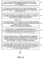
- Figures 4A and 4B summarize an example method of exchanging data plane management frames for load balancing of identified traffic classes in the loop-free routing topology of Figure 1 , according to an example embodiment.
- the operations described with respect to any of the Figures can be implemented as executable code stored on a computer or machine readable non-transitory tangible storage medium (e.g., floppy disk, hard disk, ROM, EEPROM, nonvolatile RAM, CD-ROM, etc.) that are completed based on execution of the code by a processor circuit implemented using one or more integrated circuits; the operations described herein also can be implemented as executable logic that is encoded in one or more non-transitory tangible media for execution (e.g., programmable logic arrays or devices, field programmable gate arrays, programmable array logic, application specific integrated circuits, etc.).
- one or more non-transitory tangible media can be encoded with logic for execution by a machine, and when executed by the machine operable for the operations described herein.
- the network controller 36 in operation 40 can create a loop-free routing topology 10 for each network device 18 in the data network; in other words, the creation of a loop-free routing topology 10 in operation 40 by the network controller 36 can be repeated for each network device 18 in the data network.
- the loop-free routing topology 10 comprising routing arcs 12 can be created by the processor circuit 32 of the network controller 36 based on various techniques, for example as described in U.S. Patent Publication No. 2012/0300668 , U.S. Patent No. 8,897,135 , etc., for example based on directed acyclic graphs, MRTs, etc.
- the network controller 36 also can construct a loop-free routing topology 10 based on split-ring topologies as described for example in U.S. Patent Publication No. U.S. Patent Publication No. 2014/0078927 .
- the network controller 36 in operation 40 can at least initially establish the loop-free routing topology 10 and provide high-level control of the loop-free routing topology 10 based on sending control plane Operations, Administration, and Maintenance (OAM) messages to each of the network devices 18 in the data network.
- OAM Operations, Administration, and Maintenance
- a loop-free routing topology 10 can be created in operation 40 based the network controller 36 attempting to establish every network node, except the root network node and the heir network nodes, as junction nodes, in order to guarantee that every network node has a shortest path and an alternate path to a destination device (i.e., the root network node) 14. This guarantee is established by creating routing arcs 12 that terminate at safe network nodes.
- the example embodiments enable a link to be reversed in response to a detected failure in a network node or network link, enabling immediate rerouting of data traffic without route recalculation and without the formation of any loops in the topology.
- the network controller 36 in operation 40 can establish a loop-free routing topology of routing arcs for reaching a root network node, the loop-free routing topology consisting of a root network node, two or more heir network nodes coupled to the root network node, junction nodes, and zero or more leaf network nodes.
- Leaf network nodes are not shown in the attached Figures to reduce unnecessary complexity in the figures; hence, leaf network nodes can be attached to network devices 18 of the loop-free routing topology 10 even though not shown in the Figures.
- the loop-free routing topology 10 can be created by the network controller 36 in operation 40 based on: generating a first directed acyclic graph for reaching the destination device 14; identifying (within the first directed acyclic graph) junction nodes that have non-congruent paths for reaching the destination device 14; identifying links between the junction nodes that can be bidirectional links 22, or reversed if needed ("reversible links"), along the non-congruent paths, and that do not introduce or create a loop in the loop-free routing topology 10; and identifying at least one second directed acyclic graph within the first directed acyclic graph (also referred to as a "subDAG”) for reaching one of the junction nodes, the second directed acyclic graph including an identified new junction node having a new non-congruent path for reaching the destination device.
- a first directed acyclic graph for reaching the destination device 14
- the network controller 36 in operation 36 can construct a first of the infrastructure arcs (e.g., 12a and/or 12b) comprising two or more of the junction nodes and one or more bidirectional links 22, the first of the infrastructure arcs having the corresponding first end terminating at the destination device; the network controller 36 also can construct a second of the routing arcs (e.g., 12c, 12d, and/or 12e) can be after the first of the routing arcs (e.g., 12a and/or 12b) and having the corresponding first end 20 terminating at the first of the routing arcs.
- a first of the infrastructure arcs e.g., 12a and/or 12b
- a second of the routing arcs e.g., 12c, 12d, and/or 12e
- the loop-free routing topology 10 has a plurality of the routing arcs 12 and can consist of the destination device 14, zero or more leaf nodes each having only one data link, and the plurality of junction nodes (e.g., edge junctions "B2" or “E4", edge nodes “E1” or “E5", collapsed-arc center junction nodes “F1", or intermediate junctions "E2", “E3”, or “E4").
- junction nodes e.g., edge junctions "B2" or “E4", edge nodes “E1” or “E5", collapsed-arc center junction nodes "F1", or intermediate junctions "E2", "E3", or “E4".
- Other techniques for constructing the loop-free routing topology 10 can be used.
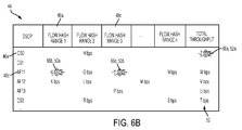
- the network controller 36 in operation 42 can send to each network device 18 an OAM message (in the control plane) specifying parameters for storing a traffic table (44 of Figure 3 and 6A ) that can identify one or more traffic classes (46 of Figure 6A-6F ) and can identify one or more hash-based ranges (48 of Figure 6A-F ) for each of the identified traffic class (e.g., 46a, 46b, 46c, 46d, 46e, or 46f).
- the number of identified traffic classes 46 can be chosen by the network controller 36 to optimize the "granularity" (i.e., precision) required to distinguish between different traffic flows for a given identified traffic class 46.
- the memory circuit 34 of each network device 18 in operation 42 can store in its memory circuit 34 the traffic table 44 that comprises a range-specific traffic value 50 for a corresponding identified traffic class 46 and hash-based range 48, and a class-based traffic value 52 that aggregates all the range-specific traffic values 50 for all the hash-based ranges 48 of a given identified traffic class 46.
- Other techniques can be used for storing the traffic table 44.
- Each identified traffic class 46 can be identified based on various attributes for identification of network traffic (e.g., network "flows"), for example as Differentiated Services (“DiffServ") based on class selector (CS) code point (e.g., 46a, 46b, and/or 46f), assured forwarding (AF) class (e.g., 46c, 46d, and/or 46e), etc.
- DiffServ Differentiated Services
- CS class selector
- AF assured forwarding
- Other techniques for identifying traffic can be used, for example according to RFC 7011.
- Each hash-based range 48 can be generated using various techniques, for example according to RFC 7014.
- the processor circuit 32 of each network device 18 is configured for storing in operation 54 traffic policies for each identified traffic class 46 and hash-based ranges 48 in a traffic policy table 56 stored in the memory circuit 34.
- the traffic policy table 56 can specify, for each hash-based range 48 of an identified traffic class 46, one or more traffic policies associated with the corresponding hash-based range 48 of the identified traffic class 46.
- Example traffic policies can include QoS priority values, guaranteed QoS parameters, minimum (or maximum) guaranteed bandwidth values (e.g., bits per second (bps)), jitter values, etc.
- the traffic policies can be supplied by an OAM message from the network controller 36; other techniques can be used by the network device 18 for storing the traffic policies in the traffic policy table 56.
- the processor circuit 32 of each network device 18 can detect traffic conditions in operation 60 for one or more identified traffic classes 46 based on received data packets that are received by the corresponding device interface circuit 30.
- the processor circuit 32 can identify the identified traffic class 46 and hash-based range 48 of each received data packet, for example based on executing traffic classification, or by parsing a label specifying the identified traffic class 46 and hash-based range 48 (which can be added by an ingress network device in the data network).
- the processor circuit 32 of the network device 18 e.g., "E5") receiving a data packet can store or update in operation 60 the appropriate range-specific traffic value 50, illustrated for example in Figure 6A as a certain value of bits per second (bps).
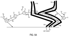
- Figure 5A illustrates the generation and output of the data-plane management frame 16a by the network device "E5" 18 based one or more detected traffic conditions caused by one or more example identified flows of data packets 58a, 58b, and 58c propagated in the routing arc 12e, according to an example embodiment.
- the identified flow 58a is identified in the traffic table 44 of the network device "E5" as belonging to the hash-based range "Flow Hash range 2" 48b within the identified traffic class "CS0" 46a; the identified flow 58b is identified in the traffic table 44 of the network device “E5" as belonging to the hash-based range "Flow Hash range 1" 48a within the identified traffic class "AF11” 46c; and the identified flow 58c is identified in the traffic table 44 of the network device "E5" as belonging to the hash-based range "Flow Hash range 3" 48c within the identified traffic class "AF11” 46c.
- the identified flow 58a enters the routing arc 12e via the edge link 24 into the network device "E3" 18, and via the edge link 24 entering into the network device "F1" 18 of the collapsed routing arc 12f which forwards the identified flow 58a to the edge junction "E4" 18.
- the identified flow 58b enters the routing arc 12e via the edge link 24 into the network device "E3” 18.
- the identified flow 58c enters the routing arc 12e via the edge link 24 entering into the network device "F1" 18 of the collapsed routing arc 12f which forwards the identified flow 58a to the edge junction "E4" 18.
- the edge junction "E4" 18 forwards the identified flows 58a, 58b, and 58c to the next-hop edge node "E5" 18.
- the processor circuit 32 In response to the device interface circuit 30 of the edge node "E5" 18 receiving in operation 60 each of the identified flows 58a, 58b, and 58c, the processor circuit 32 (e.g., a forwarding ASIC in the network device 18) can update the respective range-specific traffic values 50 in the traffic table 44 stored in the memory circuit 34 of the edge node "E5".
- the range-specific traffic values 50 can be stored as traffic statistics, etc. indexed by the traffic class 46 and hash-based range 48.
- the processor circuit 32 of the edge node “E5" 18 can determine or detect in operation 62 whether there is a load balancing change event that affects the proximate (i.e., nearest) routing arc edge 20a, for example that affects the edge node "E5" itself or that affects the adjacent edge link 24 that supplies data traffic from the edge node E5" 18 to the network device "B1" 18.
- the processor circuit 32 of the edge node “E5" 18 can detect a load balancing change event based on whether any one of the range-specific traffic values 50 exceeds a corresponding policy value specified in the traffic policy table 56 (e.g., due to burst traffic or an identification of higher-priority data traffic or data traffic requiring a higher QoS).
- the processor circuit 32 of the edge node "E5" 18 also can detect a load balancing change event based actual or potential overflows, for example based on DSCP-based detection such as random early detection (RED) and/or explicit congestion notification (ECN) relative to policies stored in the traffic policy table 56.
- a policy stored in the traffic policy table 56 can identify overload levels based on DSCP classification, for example per hash-based range 48 of a class-based traffic value 52, per a group of hash-based ranges 48 for identified traffic class 46, for an entire identified traffic class 46, and/or for a global aggregate value for aggregate traffic output by the network device 18.
- the processor circuit 32 of the edge node "E5" 18 also can detect a load balancing change event based on a deteriorated condition in the edge link 24, for example due to a degraded wireless data link due to radio frequency (RF) interference, etc.
- RF radio frequency
- the load balancing change event detection in operation 62 by the processor circuit 32 of the edge node "E5" 18 can be based on rules stored in the traffic policy table 56 and associated with the policies for each of the identified traffic classes 46, each of the hash-based ranges 48 or group thereof for an identified traffic class 46, etc.
- the rules stored in the traffic policy table 56 can indicate relative priorities or precedence for selection of data flows that should be marked as "overflow", e.g., DSCPs that can be rerouted; for example, whether an assured forwarding class (AF) due to a large amount of traffic, or whether a CS class should be rerouted during instances of low traffic.
- the processor circuit 32 of the edge node "E5" 18 can determine or detect in operation 62 with respect to the traffic policy table 56: the load balancing change event 66a in Figure 6B with respect to the class-based traffic value "Z bps" 52a for the identified traffic class "CS0" 46 of the identified flow 58a of Figure 5A ; the load balancing change event 66b in Figure 6B with respect to the range-specific traffic value "X bps" 50a for the identified flow 58b; and the load balancing change event 66c in Figure 6B with respect to the range-specific traffic value "Y bps" 50b for the identified flow 58c.
- the processor circuit 32 of the edge node "E5" 18 can determine in operation 62 that it wishes to reroute the associated identified flows 58a, 58b, and 58c away from the "proximate" edge 20a (e.g., away from itself and/or the connecting edge link 24) and toward a "second" edge 20b.
- the processor circuit 32 can determine in operation 62 whether there is a load balancing change event on a periodic basis and/or a triggered event.
- the processor circuit 32 of the edge node "E5" 18 in operation 68 can generate and send a data-plane management frame 16a, implemented for example as a JOAN frame, specifying one or more requests for changes in load balancing (e.g., 70a, 70b, and/or 70c of Figure 6C ) for rerouting the identified traffic classes from the edge 20a toward the edge 20b.
- the data-plane management frame 16a also can be referred to as a load balancing request message.
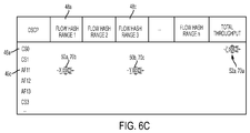
- Figure 6C illustrates specifies change requests 70a, 70b, and 70c that are generated by the processor circuit 32 of the requesting edge node "E5" 18 with respect to the respective load balancing change events 66a, 66b, and 66c, for insertion into the data-plane management frame 16a.
- the processor circuit 32 of the requesting edge node "E5" 18 can specify within the data-plane management frame 16a the change request 70a for rerouting all traffic flows (58a of Figures 5A-5C ) from the edge 20a (as in Figure 5A ) toward the edge 20b (as in Figures 5B and 5C ) for the identified traffic class "CS0" 46a (having a class-based traffic value 52a of "Z bps"); the processor circuit 32 of the requesting edge node "E5" also can specify within the data-plane management frame 16a the change request 70b for rerouting, from the edge 20a toward the edge 20b, the traffic flow (58b of Figure 5A ) associated with the hash-based range "Flow Hash Range 1" 48a having the range-specific traffic value "X bps" 50a for the identified traffic class "AF11” 46c; the processor circuit 32 of the edge node "E5" also can specify within the data-plane management frame 16a the change request 70c for rerouting
- each change request 70 can specify the traffic limit expected as part of the change request, e.g., "Z bps" 52a for the change request 70a, "X bps" 50a for the change request 70b, and "Y bps" 50b for the change request 70c.
- the data-plane management frame 16a need not necessarily have the format as illustrated in Figure 6C , but can at least identify the change requests 70 and a target address for the second edge node "E1" 18 serving the second edge 20b.
- the device interface circuit 30 of the requesting edge node "E5" 18 is configured for sending or outputting in operation 68 the data-plane management frame 16a via the data plane path 26a of the routing arc 12e toward the edge 20b (illustrated in Figure 2 ), for initiating of the load balancing based on negotiation with the edge node "E1" 18. Additional details with respect to JOAN frames can be found in U.S. Publication No. 2015/0163091 .
- each intermediate network device e.g., "E4", "E3", and "E2" 18 in the data plane path 26a can receive, parse and interpret the data-plane management frame 16a prior to forwarding the data-plane management frame 16a along the data plane path 26a.
- Each intermediate network device in the data plane path 26a can compare each of the change requests (e.g., 70a, 70b, and 70c) specified in the received data-plane management frame 16a with its traffic table 44 and traffic policy table 56 to determine whether it can accept the change requests 70.
- the processor circuit 32 of the network device "E2" 18 determines that it cannot accept (and must reject) one or more of the change requests (e.g.,70c) (referred to as an intermediate-rejected change request)
- the processor circuit 32 of the network device "E2" 18 in response can send a reject response (e.g., as a JOAN frame) back to the requesting edge node "E5" 18 having originated the data-plane management frame 16a indicating at least rejection of the intermediate-rejected change request.
- the intermediate network device (e.g., "E2") 18 that is "upstream" of the target edge device “E1" 18 can drop the data-plane management frame 16 and respond to the requesting network device "E5" 18 if the intermediate network device 18 cannot accept one or more of the change requests (e.g., 70c) (i.e., one or more intermediate-rejected change requests); the intermediate network device 18 also can send a "courtesy" notice message (e.g., as a JOAN frame) to the target edge device "E1" indicating that the data-plane management frame 16a was rejected.
- a "courtesy" notice message e.g., as a JOAN frame
- the processor circuit 32 of the intermediate network device (e.g., "E2") 18 having rejected the one or more intermediate-rejected change requests (e.g., 70c) can forward toward the edge device "E1" 18 a modified data-plane management frame 16 that includes the non-rejected change requests (e.g., 70a, 70b) and that does not include the intermediate-rejected change request (e.g., 70c) that was rejected by the intermediate network device (e.g., "E2").
- the intermediate network device can respond to the intermediate-rejected change request (e.g., 70c) by sending a reject response back to the requesting edge node "E5" specifying the rejection of the intermediate-rejected change request (e.g., 70c).
- the reject response also can specify a counter-request generated by the intermediate network device (e.g., "E2").
- device interface circuit 30 of the second edge "E1"18 in operation 74 can receive the data-plane management frame 16a from the data plane path 26a.
- the processor circuit 32 of the second edge device “E1"18 in operation 74 can determine whether any identified traffic in the change requests 70 specified in the data-plane management frame 16a can be accepted, based on comparing the change requests 70 with the current traffic flows identified in its traffic table 44 (e.g., the range-specific traffic values 50 and the class-based traffic values 52) relative to the policies in its traffic policy table 56.
- the processor circuit 32 of the second edge device "E1" 18 in operation 76 can generate and send a second data-plane management frame 16b toward the requesting edge device "E5" 18 via the data plane path 26b.
- the processor circuit 32 of the second edge device "E1" 18 in operation 76 can determine and generate at least one of an acceptance 78, a rejection 80, or a counter-request 82 associated with one or more of the change requests 70 specified in the data-plane management frame 16a.
- the data-plane management frame 16b generated by the processor circuit 32 of the second edge device "E1" can specify the acceptance 78a relative to the change request 70a, the acceptance 78b relative to the change request 70b, and a rejection 80 relative to the change request 70c.
- the processor circuit 32 of the second edge device “E1" also can generate a new request, referred to as a "counter-request” 82, that can be either responsive to the data-plane management frame 16a or independent of the data-plane management frame 16a.
- the data-plane management frame 16b output by the device interface circuit 30 of the second edge device “E1" 18 via the data plane path 26b for delivery to the requesting network device "E5" can specify the acceptances 78a and 78b, the rejection 80, and/or the counter-request 82.
- the processor circuit 32 of the second edge device "E1" 18 in operation 76 also can update its forwarding table (84 of Figure 3 ) to specify that the identified flow 58a associated with the acceptance 78a, and the identified flow 58b associated with the acceptance 78b should be forwarded to the next-hop node "A1" 18 via the edge link 24 (as illustrated in Figure 5B ) (e.g., change forwarding table entry from "right” to "left"), and that flows associated with the counter-request 82 should be dropped and pushed back on the incoming link (e.g., intra-arc link 22 between network devices "E1" and "E2").
- the forwarding table 84 of Figure 3
- the intermediate network devices "E2", “E3”, and “E4" along the data plane path 26b also can respond in operation 84 to the second data-plane management frame 16b based on the acceptance 78a, the acceptance 78b, and the rejection 80, prior to forwarding the data-plane management frame 16b toward the requesting edge device "E5" 18.
- the processor circuit 32 of the intermediate network device “E3” can implement in operation 84a the acceptance 78a and the acceptance 78b based on updating the respective forwarding table entries in its forwarding table 84 to specify that the respective associated flows 58a and 58b should be forwarded toward the edge 20b (e.g., via the edge device "E1" or "left"), illustrated in Figure 5B .
- each intermediate network device “E2", “E3”, and “E4" 18 can specify that the forwarding table entry in the forwarding table 84 for the identified flow 58a should be changed from “right” (toward the edge 20a) to "left” (toward the edge 20b), enabling each of the intermediate network devices “E2", “E3”, and “E4" to redirect/reroute the identified flow 58a and the identified flow 58b away from the edge 20a and toward the edge 20b as in Figure 5B .
- each intermediate network device “E2", “E3” and “E4" 18 in operation 84b also can implement the rejection 80 based on updating the forwarding table entry in its forwarding table 84 to specify that the identified flow 58c should be dropped (illustrated as blockage 86 of Figure 5B ), and pushed back onto the incoming link toward the sourcing network device, described below.
- the data-plane management frame 16b is forwarded toward the requesting network device "E5" 18.
- the processor circuit 32 of the requesting network device "E5" 18 in operation 94 updates the local flow components in its forwarding table 84, for example specifying that the flows 58a and 59b are to be sent "left" toward the edge 20b, and depending on implementation that the identified flow 58c is either maintained (e.g., to the "right” toward edge 20) or dropped (based on the rejection 80).
- the processor circuit 32 of the requesting network device "E5" 18 in operation 94 also can respond to the counter-request 82 with a counter-response, for example another acceptance 78, a rejection 80, or another counter-request 82.
- the edge junction "E4" 18 is an incoming edge for the upstream arc 12f sourcing the identified flow 58c (received by the network device "F1" via the edge link 24 of Figure 2 ).
- the processor circuit 32 of the edge junction "E4" 18 in operation 90 can respond to the rejection 80 by generating its own data-plane management frame 16c (shown in Figure 2 ) specifying the change request 70c, and outputting the data-plane management frame 16c toward the distant junction node "B2" 18 via the data plane path 26c.
- the processor circuit 32 of the edge junction "E4" 18 can treat the rejection 80 as a new load balancing change event in operations 62, 68 and "recurse” or “propagate” the rejected change request 70c as a new change request 70c' (illustrated in Figure 6E ) into the upstream arc 12f toward the source of the identified flow 58c, to enable searching for an alternative route for the identified flow 58c.
- the edge junction "B2" 18 can respond to the data-plane management frame 16c based on generating and output a data-plane management frame 16d (operations 74, 76) via the data plane path 26d.
- the network device "F1" can redirect/reroute the identified flow 58c based on updating its forwarding table 84 to specify that the identified flow 58c should be sent "right” to the network device "B2" 18; the edge junction "E4" 18 can update its forwarding table 84 to remove the blockage 86 and specify that any receipt of the identified flow 58c should be "pushed back" toward the network device "F1” for rerouting by the network device "F1" toward the network device "B2" of routing arc 12b, as illustrated in Figure 5C .
- class-aware load balancing can be implemented using a data-plane protocol in a loop-free multiple edge network topology, without the necessary of transferring any arc cursor that otherwise claims exclusive authority for routing network traffic in a routing arc.
- the loop-free routing topology can be constructed using various techniques, for example based on directed acyclic graphs (DAGs), outer paths of MRTs (also referred to as "ears"), etc.
- Management frames can be forwarded between network devices in the data-plane protocol, enabling network devices to negotiate load-balancing decisions for rerouting of network traffic according to identified traffic classes based on identified policies, without the intervention of a network manager operating or network controller on a control plane.
- the load balancing as described herein can be initiated by any network device in the loop-free routing topology that is not a leaf node.
- a method comprises detecting a traffic condition by a network device in a loop-free routing topology comprising routing arcs for reaching a destination device, each routing arc comprising a first edge, a second edge, and at least a third network device configured for routing any network traffic along the routing arc toward the destination device and exiting via any one of the first or second edges of the routing arc, the traffic condition proximate to the first edge of at least one of the routing arcs in which the network device is positioned; and the network device initiating load balancing based on sending a management frame over a data plane of the at least one routing arc toward the corresponding second edge, the management frame requesting a change in load balancing for at least one of an identified traffic class based on the detected traffic condition.
Landscapes
- Engineering & Computer Science (AREA)
- Computer Networks & Wireless Communication (AREA)
- Signal Processing (AREA)
- Data Exchanges In Wide-Area Networks (AREA)
Abstract
Description
- The present disclosure generally relates to class-aware load balancing using a data plane protocol in a loop-free multiple edge network topology.
- This section describes approaches that could be employed, but are not necessarily approaches that have been previously conceived or employed. Hence, unless explicitly specified otherwise, any approaches described in this section are not prior art to the claims in this application, and any approaches described in this section are not admitted to be prior art by inclusion in this section.
- A data network routes network traffic in the form of data packets to and from one or more destination devices via network links. A network topology is established that identifies one or more paths for reaching a destination device, enabling the data packets to be forwarded along the one or more paths. Particular concerns in deploying an effective network topology include ensuring that the network topology is resilient to link failures without the formation of loops, and ensuring that network traffic can be controlled based on effective load balancing techniques.
- One proposed loop-free routing topology includes routing arcs that provide resilience to link failures: the routing arcs enable the network traffic to be routed along any of two ends of any routing arc; the routing arcs also enable instantaneous rerouting of network traffic to a destination device in response to a detected failure of a data link, based on reversing an identified reversible link within the routing arc. Load balancing in the loop-free routing topology is based on "intra-arc" traffic management within a routing arc by an "arc cursor" node having exclusive authority for determining the direction of data traffic within the routing arc, and "inter-arc" management between routing arcs based on propagation of backpressure commands by a given routing arc to a "parent" routing arc supplying data traffic to the given routing arc.
- Aspects and examples of the present invention are set out in the appended claims.
- Reference is made to the attached drawings, wherein elements having the same reference numeral designations represent like elements throughout and wherein:
-
Figure 1 illustrates an example loop-free routing topology comprising a plurality of routing arcs for reaching a destination device based on class-aware load balancing of an identified traffic class, according to an example embodiment. -
Figure 2 illustrates an exchange of data plane management frames, specifying load-balancing information for identified traffic classes, within an example routing arc from the loop-free routing topology ofFigure 1 according to an example embodiment. -
Figure 3 illustrates an example apparatus implemented as any one of the network devices ofFigures 1 or2 and configured for exchanging data plane management frames for load balancing of identified traffic classes, according to an example embodiment. -
Figures 4A and4B summarize an example method of exchanging data plane management frames for load balancing of identified traffic classes in the loop-free routing topology ofFigure 1 , according to an example embodiment. -
Figures 5A-5C illustrate load balancing identified traffic classes in the example routing arc ofFigure 2 based on exchange of data plane management frames, according to an example embodiment. -
Figures 6A-6F illustrate example data structures generated by the network devices for load balancing of identified traffic classes in the loop-free routing topology ofFigure 1 , according to an example embodiment. - In one embodiment, a method comprises detecting a traffic condition by a network device in a loop-free routing topology comprising routing arcs for reaching a destination device, each routing arc comprising a first edge, a second edge, and at least a third network device configured for routing any network traffic along the routing arc toward the destination device and exiting via any one of the first or second edges of the routing arc, the traffic condition proximate to the first edge of at least one of the routing arcs in which the network device is positioned; and the network device initiating load balancing based on sending a management frame over a data plane of the at least one routing arc toward the corresponding second edge, the management frame requesting a change in load balancing for at least one of an identified traffic class based on the detected traffic condition.
- In another embodiment, an apparatus comprises a processor circuit and a device interface circuit. The processor circuit is configured for detecting a traffic condition in a loop-free routing topology comprising routing arcs for reaching a destination device. Each routing arc comprises a first edge, a second edge, and at least a third network device configured for routing any network traffic along the routing arc toward the destination device and exiting via any one of the first or second edges of the routing arc. The traffic condition is proximate to the first edge of at least one of the routing arcs in which the apparatus is positioned as a network device. The processor circuit further is configured for initiating load balancing based on generating a management frame requesting a change in load balancing for at least one of an identified traffic class based on the detected traffic condition. The device interface circuit is configured for sending the management frame over a data plane of the at least one routing arc toward the corresponding second edge, for initiating of the load balancing.
- In another embodiment, or more non-transitory tangible media is encoded with logic for execution by a machine and when executed by the machine operable for: detecting a traffic condition by the machine implemented as a network device in a loop-free routing topology comprising routing arcs for reaching a destination device, each routing arc comprising a first edge, a second edge, and at least a third network device configured for routing any network traffic along the routing arc toward the destination device and exiting via any one of the first or second edges of the routing arc, the traffic condition proximate to the first edge of at least one of the routing arcs in which the network device is positioned; and the network device initiating load balancing based on sending a management frame over a data plane of the at least one routing arc toward the corresponding second edge, the management frame requesting a change in load balancing for at least one of an identified traffic class based on the detected traffic condition.
- Particular embodiments enable load balancing of identified traffic classes in a loop-free routing topology using management frames sent over routing arcs according to a data-plane protocol. The loop-free routing topology is created for reaching a destination device, and comprises plural routing arcs for reaching the destination device via any one of first or second edges of each routing arc. The exchange of management frames according to the data-plane protocol enables each network device in a routing arc to participate in implementing load-balancing decisions for the propagation of the identified traffic classes through the routing arc for exiting via either of the first or second edges.
- Hence, the exchange of management frames over the data plane of a routing arc enables identified traffic classes, and even selected subsets (i.e., "ranges") of the identified traffic classes, to be propagated to either edge of the routing arc based on negotiation and implementation of traffic policies between the network devices in the routing arc, independent of any arc cursor in the routing arc that would otherwise be used to control network traffic in the routing arc. Hence, an identified traffic class (or selected subset thereof) can be redirected through a routing arc by the network devices, independent of any arc cursor, based on negotiated traffic policies. Example traffic policies can include redirecting lower-priority (e.g., low Quality of Service (QoS)) traffic, allocation of bandwidth or throughput among the selected subsets of the identified traffic classes, traffic shaping among the selected subsets of the identified traffic classes (e.g., due to data bursts, etc.), etc.
- Hence, the example embodiments can provide traffic shaping in the loop-free routing topology, independent of any arc cursor, based on exchange of management frames over the data plane of one or more routing arcs for negotiation and implementation of traffic polices. The traffic shaping provided by the example embodiments can minimize dropped packets due to congestion or backpressure commands, since network devices in a routing arc can "tune" traffic flows based on the management frames.
-
Figure 1 is a diagram illustrating an example data network of network devices, where the data network has a loop-free routing topology 10 comprisingrouting arcs 12 for reaching adestination device 14 based on class-aware load balancing provided by data-plane management frames 16, according to an example embodiment. The data network can be a stand-alone network or a subnetwork of a larger network such as a local area network (LAN), a Wide Area Network (WAN), etc. The data network can be implemented via any type of data link layer protocol, for example a low-power wireless network (e.g., a Low-Power and Lossy Network), a wired network, etc. Thenetwork devices 18 of the data network can be connected by wired or wireless data links (e.g., a mesh network), and a routing topology overlying the data links can be constructed for reaching acorresponding network device 18. The "destination device" 14 can be any network device in the data network; hence, each network device in a data network can have its own corresponding loop-free routing topology 10 constructed to ensure reachability to the "destination"device 14 via its own set ofrouting arcs 12. - Each
routing arc 12 comprises a plurality ofnetwork devices 18 each having at least two data links for reaching adjacent network nodes (for simplicity,Figure 1 illustrates only one of themultiple network devices 18 as network device "X" 18). Eachrouting arc 12 has at least twoedges 20, illustrated as "arrowheads" 20 inFigure 1 , where network traffic can be routed along anyrouting arc 12 toward thedestination device 14, and exit therouting arc 12, via any one of the first orsecond edges 20 of therouting arc 12. As illustrated inFigure 1 , twoedges 20 of therouting arc 12a androuting arc 12b exit at thedestination device 14; oneedge 20 of therouting arc 12c exits at thedestination device 14 while anotheredge 20 of therouting arc 12c exits at therouting arc 12b; twoedges 20 of therouting arc 12d exit at therouting arc 12a; and oneedge 20 of therouting arc 12e exits at therouting arc 12a while anotheredge 20 of therouting arc 12e exits at therouting arc 12b. - Hence, the
edge 20 of eachrouting arc 12 provides an exit point for data traffic from therouting arc 12 to either a "downstream" arc or thedestination device 14. Although not shown inFigure 1 , arouting arc 12 can have more than two edges 20 (in which thethird edge 20 can be based on a buttressing arc that converts a routing arc into a comb structure), illustrated for example inU.S. Patent Publication No. 2013/0301470 . - As apparent from
Figure 1 , the loop-free routing topology 10 guarantees that anynetwork device 18 along any point of any arc routing 12 (e.g., network device "X" inFigure 1 ) has at least two non-congruent paths for reaching thedestination device 14, guaranteeing reachability to thedestination device 14 even if a link failure is encountered in the loop-free routing topology 10. The term "node" in the specification and claims refers to a network device (i.e., apparatus, machine, etc.) that is assigned an identifiable position within therouting topology 10. - The loop-
free routing topology 10 for eachdestination device 14 can be constructed based on operations executed by one or more network routers, a centralized server, a network management entity, etc. For example, anetwork controller device 36 can at least initially establish the loop-free routing topology 10 and provide high-level control of the loop-free routing topology 10 based on sending control plane Operations, Administration, and Maintenance (OAM) messages to each of thenetwork devices 18 in the data network. The OAM messages are also referred to herein as "OAM frames". Therouting arcs 12 forming the loop-free routing topology 10 can be constructed from one or more directed acyclic graphs (DAGs), one or more a tree-based topologies (e.g., a maximally-redundant tree (MRT)), split-ring topologies, etc.). Additional example techniques for creating the loop-free routing topology 10 are described inU.S. Patent Publication No. 2012/0300668 ,U.S. Patent Publication No. 2013/0301470 ,U.S. Patent Publication No. 2014/0078927 ,U.S. Patent Publication No. 2015/0163091 , and/orU.S. Patent No. 8,897,135 . - The loop-free routing topology as described in each of
U.S. Patent Publication No. 2012/0300668 ,U.S. Patent Publication No. 2013/0301470 ,U.S. Patent Publication No. 2014/0078927 ,U.S. Patent Publication No. 2015/0163091 , and/orU.S. Patent No. 8,897,135 , is based on an assumption that eachrouting arc 12 includes one and only one arc cursor that provides exclusive control of directing the network traffic along the corresponding routing arc and away from any network device having possession of the arc cursor; hence, these prior descriptions of the loop-free routing topology describe that network traffic in a routing arc is controlled exclusively by the network device having possession of the arc cursor, such that any change in control in a routing arc is based on transferring possession of the arc cursor from the network device having possession thereof to another network device within the routing arc. -
Figure 2 illustrates an exchange of data-plane management frames 16 (e.g., 16a, 16b, 16c, and 16d) for initiating load balancing of identified traffic classes within example routing arcs (e.g., 12e and 12f) of the loop-free routing topology 10 ofFigure 1 , according to an example embodiment. According to example embodiments, load balancing in the loop-free routing topology 10 can be executed between network devices (18 ofFigures 1 and2 ) based on thenetwork devices 18 exchangingmanagement frames 16 over a data plane of at least onerouting arc 12, the data-plane management frames 16 specifying load-balancing information for identified traffic classes. In particular, control messages (e.g., OAM messages) sent in the control plane typically are unicast from a source device (e.g., a management entity device 36) to a targeted device (e.g., a managed device such as "E1" 18), such the control messages are parsed and interpreted only by the targeted device and are otherwise opaque to the intermediate network devices, i.e., no network device forwarding a control message from thesource device 36 to the targeted device (e.g., "E1" 18) would parse or interpret the control message. - In contrast, the
network devices 18 can receive and forward network traffic (e.g., data packets) along arouting arc 12 via their associated data links 22 (i.e., intra-arc links). Sincenetwork devices 18 "forward" network traffic to each other toward thedestination device 14, thenetwork devices 18 are deemed to forward the network traffic in a "forwarding plane" of therouting arcs 12 of the loop-free routing topology 10. The "forwarding plane" and the "data plane" are synonymous and may be used interchangeably. - According to an example embodiment, the data-
plane management frames 16 exchanged betweennetwork devices 18, also referred to as Joint Operation and Automation of the Network (JOAN) frames, enable eachnetwork device 18 receiving the data-plane management frame 16 to parse and interpret the received data-plane management frame 16 for selective execution of load balancing operations on at least one of an identified traffic class. A JOAN frame is a management frame that is sent over the data plane of at least onerouting arc 12, and that can be parsed and interpreted by anynetwork device 18 receiving the data-plane management frame 16. A data-plane management frame 16 can be generated and output by anynetwork device 18 in anyrouting arc 12 at any time as appropriate, for example on a periodic basis and/or a triggering event. - A data-
plane management frame 16 can be output or sent by anetwork device 18 over the data plane of a routing arc 12 (i.e., a data plane path 26) toward anedge 20 of therouting arc 12, enabling two ormore network devices 18 in one or more routing arcs 12 to negotiate and implement traffic policies between thenetwork devices 18 in therouting arc 12, independent of any arc cursor in therouting arc 12 that would otherwise be used to control network traffic in the routing arc. - Hence, the exchange of data-plane management frames 16 between
network devices 18 enable thenetwork devices 18 to negotiate and implement traffic policies as a substitute for an arc cursor. Alternatively, the exchange of data-plane management frames 16 betweennetwork devices 18 can be used in combination with an arc cursor. - As described in further detail below, the network devices "E5" 18 and "E1" 18 can exchange respective data-plane management frames 16a and 16b for initiation, negotiation, and implementation of load balancing of one or more identified traffic classes of network traffic that are forwarded along the
intra-arc links 22 of therouting arc 12e. The network devices "E4" 18 and B2" 18 also can exchange respective data-plane management frames 16c and 16d for initiation, negotiation, and implementation of load balancing of one or more identified traffic classes of network traffic, that are forwarded from the network device "F1" (e.g., from a network device in an "upstream" routing arc (not shown inFigure 2 )), along one or more of theintra-arc links 22 of the collapsedrouting arc 12f to therouting arc 12e or therouting arc 12b. - The "edge" 20 of a
first routing arc 12 as used in this specification and the claims refers to an "end" point where a data packet exits thefirst routing arc 12 and either enters a second "downstream" routingarc 12, or enters an "edge link" 24 that couples thefirst routing arc 12 to either another (third) "downstream" routingarc 12 or to thedestination device 14. As described in further detail, an "edge" 20 can refer to any one of anedge link 24, an edge junction (e.g., junction node "B2" or "E4") that belongs to a collapsed routing arc (e.g., 12f) and anotherrouting arc 12, or an edge node (e.g., "E1", E5") that output data traffic to another routing arc (e.g., 12a or 12b) via anedge link 24. For example, thecollapsed routing arc 12f has only network devices "F1" 18 for receiving network traffic from an "upstream" routing arc (not shown) via anedge link 24, an edge junction "E4" that enables the network traffic of the collapsedrouting arc 12f to exit into therouting arc 12e, and an edge junction "B2" that enables the network traffic of the collapsedrouting arc 12f to exit into therouting arc 12b. Hence, the edge junctions "E4" and "B2" can generate and transmit respective data-plane management frames 16c and 16d for load balancing of identified traffic classes in the collapsedrouting arc 12f. An edge junction can belong to one or more collapsed routing arcs. - In contrast, the
routing arc 12e comprises network devices "E1", "E2", "E3", "E4", and "E5", where the edge nodes "E1" and "E5" can generate and transmit respective data-plane management frames 16a and 16b for load balancing of identified traffic classes in therouting arc 12e. The network devices "A1" and "B1" are not edge nodes of therouting arc 12e because they will not participate in load balancing within therouting arc 12; however, the network device "A1" is an edge node ofrouting arc 12a and network device "B1" is an edge node ofrouting arc 12b. As described below, the intermediate network devices "E2", "E3", and "E4" (i.e., intermediate junction nodes) in between the edge nodes "E1" and "E5" also can generate and transmit a data-plane management frame 16, as appropriate. - A "junction" refers generally to a junction node: a junction node is defined as a network node (i.e., a network device identified based on its relative position within a network topology) that has at least two data links providing respective non-congruent paths for reaching the destination device: the term "non-congruent" in this specification and the attached claims requires that the paths from a junction node do not share any common data link for reaching the
destination device 14, rather each link belonging to one path (from the junction node to the destination device) is distinct and independent of any link belonging to the second non-congruent path (from the junction node to the destination device). An intermediate junction is defined as a junction node (or "junction network device") that terminates two and only two bidirectional links, where all other links coupled to the intermediate junction are oriented inwards to avoid loops: a link can be safely reversed towards an intermediate junction. Hence, an intermediate junction consists of two bidirectional (or reversible if needed) links and zero or more inward oriented links from any other network node. A collapsed arc does not have any intermediate junction, and an edge junction can belong to one or more collapsed arcs. - An
edge link 24 is a "one-way" wired or wireless data link that forwards data traffic in only one identified direction, whereas anintra-arc link 22 is a bidirectional wired or wireless data link that can forward data traffic in either direction (e.g., "left" or "right", "up" or "down", etc.). An intra-arc link 22 is distinct from a "reversible" link (as described inU.S. Patent Pub. 2012/0300668 ) in that a "reversible" link relied on the relative position of an arc cursor to "reverse" its direction; in contrast, the intra-arc 22 is bidirectional (i.e., both directions can be used simultaneously) because different data flows may flow in different directions simultaneously along a givenrouting arc 12. - An "heir" network node (or "heir" network device) is a network device (e.g., "A1" or "B1" of
Figure 2 ) that is directly connected to thedestination device 14. Thedestination device 14 also can be referred to as a "root" network node. In other words, adestination device 14 in any loop-free routing topology 10 comprising routing arcs must have at least two heir network nodes (e.g. network nodes "A1" and "B1") that are directly connected to the destination device 14: if an intended destination network device has only one heir node, then the only-one heir network node is designated as the new root node (based on the definition of a root network node as having no second path to reach a resource). The heir network node is used to identify a "safe" network node: if a network node can reach the root node alternatively via either a first heir network node or a second heir network node, then the network node is considered a safe network node because it can route a packet to the root via two non-congruent paths, namely either via the first heir network node or via the second heir network node, guaranteeing reachability if one of the links toward the root node is broken. - As described in further detail below, a network device 18 (e.g., "E5") in a routing arc (e.g., 12e) can detect a traffic condition proximate to (i.e., near) a "first" edge (e.g., 20a) of the routing arc (e.g., at the edge node "E5" of the
routing arc 12e or at theedge link 24 terminating at the node "B1" ofrouting arc 12b): the traffic condition can be based on thenetwork device 18 comparing a traffic value with a traffic policy for an identified traffic class. The network device (e.g., "E5") 18 also can respond to the detected traffic condition at theedge 20 of therouting arc 12e based on initiating load balancing within therouting arc 12e: the initiating of load balancing is based on the "requesting" network device (e.g., "E5") 18 sending a data-plane management frame 16 over adata plane path 26a of the routing arc 12 (e.g., 12e) that requests a change in load balancing for the identified traffic class. As described in further detail below, if the "responding" edge node (e.g., "E1") 18 receiving the data-plane management frame 16a (via thedata plane path 26a) accepts the change in load balancing, the "responding" edge node (e.g., "E1") 18 can output to the requesting network device "E5" (via thedata plane path 26b along therouting arc 12e) a data-plane management frame 16b specifying that the change in load balancing is accepted. - Each intermediate network device 18 (e.g., "E2", "E3", and "E4") along the
data plane path 26b can implement the accepted change (or refusal thereof) based on parsing and interpreting the data-plane management frame 16b in response to receipt and forwarding thereof toward the requesting edge node "E5" 18; if the data-plane management frame 16b specifies a change in load balancing is refused by the responding network device "E1", eachintermediate network device 18 can update its forwarding table (84 ofFigure 3 ) to drop the identified traffic class and reroute ("push back") the identified traffic class on its incoming link; if the data-plane management frame 16b specifies a change in load balancing is accepted by the responding network device "E1", eachintermediate network device 18 can update its forwarding table (84 ofFigure 3 ) to forward the identified traffic class toward the responding edge node E1". - Hence, the
network devices 18 in arouting arc 12 can negotiate and implement changes in load balancing for one or more identified traffic classes. Load balancing changes also can be propagated "upward" to upstream routing arcs 12, if needed. The load balancing can include rerouting identified traffic classes for congestion avoidance, ensuring guaranteed QoS of prioritized traffic flows based on rerouting lower-QoS traffic classes, temporary rerouting of identified traffic flows due to bursty traffic, etc. -
Figure 3 illustrates an example apparatus implemented as any one of thenetwork devices Figures 1 ,2 , or5A-5C , according to an example embodiment. Theapparatus physical machines 18 via the loop-free routing topology 10. Thenetwork controller 36 can be configured for communicating with thedestination device 14 and eachnetwork device 18 using OAM frames in the control plane for configuration and network management operations, including creating the loop-free routing topology 10 for reaching an identifieddestination device 14. Eachnetwork device 18 is configured for exchanging data plane management frames 16 for load balancing of identified traffic classes destined for thedestination device 14. The term "configured for" or "configured to" as used herein with respect to a specified operation refers to a device and/or machine that is physically constructed and arranged to perform the specified operation. Hence, eachapparatus free routing topology 10. - Each
apparatus device interface circuit 30, aprocessor circuit 32, and amemory circuit 34. Thedevice interface circuit 30 can include one or more distinct physical layer transceivers for communication with any one of theother devices 18; thedevice interface circuit 30 also can include an IEEE based Ethernet transceiver for communications with the devices ofFigure 1 via any of thelinks 22 and/or 24 (e.g., a wired or wireless link, an optical link, etc.). Theprocessor circuit 32 can be configured for executing any of the operations described herein, and thememory circuit 34 can be configured for storing any data or data packets as described herein. - Any of the disclosed circuits of the
devices device interface circuit 30, theprocessor circuit 32, thememory circuit 34, and their associated components) can be implemented in multiple forms. Example implementations of the disclosed circuits include hardware logic that is implemented in a logic array such as a programmable logic array (PLA), a field programmable gate array (FPGA), and/or by mask programming of integrated circuits such as an application-specific integrated circuit (ASIC). Any of these circuits also can be implemented using a software-based executable resource that is executed by a corresponding internal processor circuit such as a microprocessor circuit (not shown) and implemented using one or more integrated circuits, where execution of executable code stored in an internal memory circuit (e.g., within the memory circuit 34) causes the integrated circuit(s) implementing the processor circuit to store application state variables in processor memory, creating an executable application resource (e.g., an application instance) that performs the operations of the circuit as described herein. Hence, use of the term "circuit" in this specification refers to both a hardware-based circuit implemented using one or more integrated circuits and that includes logic for performing the described operations, or a software-based circuit that includes a processor circuit (implemented using one or more integrated circuits), the processor circuit including a reserved portion of processor memory for storage of application state data and application variables that are modified by execution of the executable code by a processor circuit. Thememory circuit 34 can be implemented, for example, using a non-volatile memory such as a programmable read only memory (PROM) or an EPROM, and/or a volatile memory such as a DRAM, etc.. - Further, any reference to "outputting a message" or "outputting a packet" (or the like) can be implemented based on creating the message/packet in the form of a data structure and storing that data structure in a non-transitory tangible memory medium in the disclosed apparatus (e.g., in a transmit buffer). Any reference to "outputting a message" or "outputting a packet" (or the like) also can include electrically transmitting (e.g., via wired electric current or wireless electric field, as appropriate) the message/packet stored in the non-transitory tangible memory medium to another network node via a communications medium (e.g., a wired or wireless link, as appropriate) (optical transmission also can be used, as appropriate). Similarly, any reference to "receiving a message" or "receiving a packet" (or the like) can be implemented based on the disclosed apparatus detecting the electrical (or optical) transmission of the message/packet on the communications medium, and storing the detected transmission as a data structure in a non-transitory tangible memory medium in the disclosed apparatus (e.g., in a receive buffer). Also note that the
memory circuit 34 can be implemented dynamically by theprocessor circuit 32, for example based on memory address assignment and partitioning executed by theprocessor circuit 32. -
Figures 4A and4B summarize an example method of exchanging data plane management frames for load balancing of identified traffic classes in the loop-free routing topology ofFigure 1 , according to an example embodiment. The operations described with respect to any of the Figures can be implemented as executable code stored on a computer or machine readable non-transitory tangible storage medium (e.g., floppy disk, hard disk, ROM, EEPROM, nonvolatile RAM, CD-ROM, etc.) that are completed based on execution of the code by a processor circuit implemented using one or more integrated circuits; the operations described herein also can be implemented as executable logic that is encoded in one or more non-transitory tangible media for execution (e.g., programmable logic arrays or devices, field programmable gate arrays, programmable array logic, application specific integrated circuits, etc.). Hence, one or more non-transitory tangible media can be encoded with logic for execution by a machine, and when executed by the machine operable for the operations described herein. - In addition, the operations described with respect to any of the Figures can be performed in any suitable order, or at least some of the operations in parallel. Execution of the operations as described herein is by way of illustration only; as such, the operations do not necessarily need to be executed by the machine-based hardware components as described herein; to the contrary, other machine-based hardware components can be used to execute the disclosed operations in any appropriate order, or at least some of the operations in parallel.
- Referring to
Figure 4A , thenetwork controller 36 inoperation 40 can create a loop-free routing topology 10 for eachnetwork device 18 in the data network; in other words, the creation of a loop-free routing topology 10 inoperation 40 by thenetwork controller 36 can be repeated for eachnetwork device 18 in the data network. The loop-free routing topology 10 comprising routing arcs 12 can be created by theprocessor circuit 32 of thenetwork controller 36 based on various techniques, for example as described inU.S. Patent Publication No. 2012/0300668 ,U.S. Patent No. 8,897,135 , etc., for example based on directed acyclic graphs, MRTs, etc. Thenetwork controller 36 also can construct a loop-free routing topology 10 based on split-ring topologies as described for example in U.S. Patent Publication No.U.S. Patent Publication No. 2014/0078927 . - The
network controller 36 inoperation 40 can at least initially establish the loop-free routing topology 10 and provide high-level control of the loop-free routing topology 10 based on sending control plane Operations, Administration, and Maintenance (OAM) messages to each of thenetwork devices 18 in the data network. - As illustrated in the
U.S. Patent Publication No. 2012/0300668 , a loop-free routing topology 10 can be created inoperation 40 based thenetwork controller 36 attempting to establish every network node, except the root network node and the heir network nodes, as junction nodes, in order to guarantee that every network node has a shortest path and an alternate path to a destination device (i.e., the root network node) 14. This guarantee is established by creating routing arcs 12 that terminate at safe network nodes. Since conventional techniques for generating a directed acyclic graph (DAG) do not guarantee that every node within a directed acyclic graph can be a junction, the example embodiments enable a link to be reversed in response to a detected failure in a network node or network link, enabling immediate rerouting of data traffic without route recalculation and without the formation of any loops in the topology. - Hence, the
network controller 36 inoperation 40 can establish a loop-free routing topology of routing arcs for reaching a root network node, the loop-free routing topology consisting of a root network node, two or more heir network nodes coupled to the root network node, junction nodes, and zero or more leaf network nodes. Leaf network nodes are not shown in the attached Figures to reduce unnecessary complexity in the figures; hence, leaf network nodes can be attached tonetwork devices 18 of the loop-free routing topology 10 even though not shown in the Figures. - The loop-
free routing topology 10 can be created by thenetwork controller 36 inoperation 40 based on: generating a first directed acyclic graph for reaching thedestination device 14; identifying (within the first directed acyclic graph) junction nodes that have non-congruent paths for reaching thedestination device 14; identifying links between the junction nodes that can bebidirectional links 22, or reversed if needed ("reversible links"), along the non-congruent paths, and that do not introduce or create a loop in the loop-free routing topology 10; and identifying at least one second directed acyclic graph within the first directed acyclic graph (also referred to as a "subDAG") for reaching one of the junction nodes, the second directed acyclic graph including an identified new junction node having a new non-congruent path for reaching the destination device. - The
network controller 36 inoperation 36 can construct a first of the infrastructure arcs (e.g., 12a and/or 12b) comprising two or more of the junction nodes and one or morebidirectional links 22, the first of the infrastructure arcs having the corresponding first end terminating at the destination device; thenetwork controller 36 also can construct a second of the routing arcs (e.g., 12c, 12d, and/or 12e) can be after the first of the routing arcs (e.g., 12a and/or 12b) and having the correspondingfirst end 20 terminating at the first of the routing arcs. Hence, the loop-free routing topology 10 has a plurality of the routing arcs 12 and can consist of thedestination device 14, zero or more leaf nodes each having only one data link, and the plurality of junction nodes (e.g., edge junctions "B2" or "E4", edge nodes "E1" or "E5", collapsed-arc center junction nodes "F1", or intermediate junctions "E2", "E3", or "E4"). Other techniques for constructing the loop-free routing topology 10 can be used. - The
network controller 36 inoperation 42 can send to eachnetwork device 18 an OAM message (in the control plane) specifying parameters for storing a traffic table (44 ofFigure 3 and6A ) that can identify one or more traffic classes (46 ofFigure 6A-6F ) and can identify one or more hash-based ranges (48 ofFigure 6A-F ) for each of the identified traffic class (e.g., 46a, 46b, 46c, 46d, 46e, or 46f). The number of identifiedtraffic classes 46 can be chosen by thenetwork controller 36 to optimize the "granularity" (i.e., precision) required to distinguish between different traffic flows for a given identifiedtraffic class 46. - As illustrated in
Figure 6A , thememory circuit 34 of eachnetwork device 18 inoperation 42 can store in itsmemory circuit 34 the traffic table 44 that comprises a range-specific traffic value 50 for a corresponding identifiedtraffic class 46 and hash-basedrange 48, and a class-basedtraffic value 52 that aggregates all the range-specific traffic values 50 for all the hash-basedranges 48 of a given identifiedtraffic class 46. Other techniques can be used for storing the traffic table 44. Each identifiedtraffic class 46 can be identified based on various attributes for identification of network traffic (e.g., network "flows"), for example as Differentiated Services ("DiffServ") based on class selector (CS) code point (e.g., 46a, 46b, and/or 46f), assured forwarding (AF) class (e.g., 46c, 46d, and/or 46e), etc. Other techniques for identifying traffic can be used, for example according to RFC 7011. Each hash-basedrange 48 can be generated using various techniques, for example according to RFC 7014. - The
processor circuit 32 of eachnetwork device 18 is configured for storing inoperation 54 traffic policies for each identifiedtraffic class 46 and hash-basedranges 48 in a traffic policy table 56 stored in thememory circuit 34. The traffic policy table 56 can specify, for each hash-basedrange 48 of an identifiedtraffic class 46, one or more traffic policies associated with the corresponding hash-basedrange 48 of the identifiedtraffic class 46. Example traffic policies can include QoS priority values, guaranteed QoS parameters, minimum (or maximum) guaranteed bandwidth values (e.g., bits per second (bps)), jitter values, etc. The traffic policies can be supplied by an OAM message from thenetwork controller 36; other techniques can be used by thenetwork device 18 for storing the traffic policies in the traffic policy table 56. - The
processor circuit 32 of each network device 18 (or at least the routing arc edges (e.g., E1, E5) can detect traffic conditions inoperation 60 for one or more identifiedtraffic classes 46 based on received data packets that are received by the correspondingdevice interface circuit 30. Theprocessor circuit 32 can identify the identifiedtraffic class 46 and hash-basedrange 48 of each received data packet, for example based on executing traffic classification, or by parsing a label specifying the identifiedtraffic class 46 and hash-based range 48 (which can be added by an ingress network device in the data network). Theprocessor circuit 32 of the network device 18 (e.g., "E5") receiving a data packet can store or update inoperation 60 the appropriate range-specific traffic value 50, illustrated for example inFigure 6A as a certain value of bits per second (bps). -
Figure 5A illustrates the generation and output of the data-plane management frame 16a by the network device "E5" 18 based one or more detected traffic conditions caused by one or more example identified flows ofdata packets routing arc 12e, according to an example embodiment. The identifiedflow 58a is identified in the traffic table 44 of the network device "E5" as belonging to the hash-based range "Flow Hash range 2" 48b within the identified traffic class "CS0" 46a; the identifiedflow 58b is identified in the traffic table 44 of the network device "E5" as belonging to the hash-based range "Flow Hash range 1" 48a within the identified traffic class "AF11" 46c; and the identifiedflow 58c is identified in the traffic table 44 of the network device "E5" as belonging to the hash-based range "Flow Hash range 3" 48c within the identified traffic class "AF11" 46c. The identifiedflow 58a enters therouting arc 12e via theedge link 24 into the network device "E3" 18, and via theedge link 24 entering into the network device "F1" 18 of the collapsedrouting arc 12f which forwards the identifiedflow 58a to the edge junction "E4" 18. The identifiedflow 58b enters therouting arc 12e via theedge link 24 into the network device "E3" 18. The identifiedflow 58c enters therouting arc 12e via theedge link 24 entering into the network device "F1" 18 of the collapsedrouting arc 12f which forwards the identifiedflow 58a to the edge junction "E4" 18. Hence, the edge junction "E4" 18 forwards the identifiedflows - In response to the
device interface circuit 30 of the edge node "E5" 18 receiving inoperation 60 each of the identifiedflows specific traffic values 50 in the traffic table 44 stored in thememory circuit 34 of the edge node "E5". The range-specific traffic values 50 can be stored as traffic statistics, etc. indexed by thetraffic class 46 and hash-basedrange 48. - The
processor circuit 32 of the edge node "E5" 18 can determine or detect inoperation 62 whether there is a load balancing change event that affects the proximate (i.e., nearest) routingarc edge 20a, for example that affects the edge node "E5" itself or that affects theadjacent edge link 24 that supplies data traffic from the edge node E5" 18 to the network device "B1" 18. For example, theprocessor circuit 32 of the edge node "E5" 18 can detect a load balancing change event based on whether any one of the range-specific traffic values 50 exceeds a corresponding policy value specified in the traffic policy table 56 (e.g., due to burst traffic or an identification of higher-priority data traffic or data traffic requiring a higher QoS). Theprocessor circuit 32 of the edge node "E5" 18 also can detect a load balancing change event based actual or potential overflows, for example based on DSCP-based detection such as random early detection (RED) and/or explicit congestion notification (ECN) relative to policies stored in the traffic policy table 56. As one example, a policy stored in the traffic policy table 56 can identify overload levels based on DSCP classification, for example per hash-basedrange 48 of a class-basedtraffic value 52, per a group of hash-basedranges 48 for identifiedtraffic class 46, for an entire identifiedtraffic class 46, and/or for a global aggregate value for aggregate traffic output by thenetwork device 18. Theprocessor circuit 32 of the edge node "E5" 18 also can detect a load balancing change event based on a deteriorated condition in theedge link 24, for example due to a degraded wireless data link due to radio frequency (RF) interference, etc. - The load balancing change event detection in
operation 62 by theprocessor circuit 32 of the edge node "E5" 18 can be based on rules stored in the traffic policy table 56 and associated with the policies for each of the identifiedtraffic classes 46, each of the hash-basedranges 48 or group thereof for an identifiedtraffic class 46, etc. The rules stored in the traffic policy table 56 can indicate relative priorities or precedence for selection of data flows that should be marked as "overflow", e.g., DSCPs that can be rerouted; for example, whether an assured forwarding class (AF) due to a large amount of traffic, or whether a CS class should be rerouted during instances of low traffic. - For example, the
processor circuit 32 of the edge node "E5" 18 can determine or detect inoperation 62 with respect to the traffic policy table 56: the load balancingchange event 66a inFigure 6B with respect to the class-based traffic value "Z bps" 52a for the identified traffic class "CS0" 46 of the identifiedflow 58a ofFigure 5A ; the load balancingchange event 66b inFigure 6B with respect to the range-specific traffic value "X bps" 50a for the identifiedflow 58b; and the load balancingchange event 66c inFigure 6B with respect to the range-specific traffic value "Y bps" 50b for the identifiedflow 58c. In other words, theprocessor circuit 32 of the edge node "E5" 18 can determine inoperation 62 that it wishes to reroute the associated identifiedflows edge 20a (e.g., away from itself and/or the connecting edge link 24) and toward a "second"edge 20b. - The
processor circuit 32 can determine inoperation 62 whether there is a load balancing change event on a periodic basis and/or a triggered event. - In response to determining one or more load balancing change events 66 the
processor circuit 32 of the edge node "E5" 18 inoperation 68 can generate and send a data-plane management frame 16a, implemented for example as a JOAN frame, specifying one or more requests for changes in load balancing (e.g., 70a, 70b, and/or 70c ofFigure 6C ) for rerouting the identified traffic classes from theedge 20a toward theedge 20b. The data-plane management frame 16a also can be referred to as a load balancing request message. -
Figure 6C illustrates specifieschange requests processor circuit 32 of the requesting edge node "E5" 18 with respect to the respective load balancingchange events plane management frame 16a. In particular, the processor circuit 32 of the requesting edge node "E5" 18 can specify within the data-plane management frame 16a the change request 70a for rerouting all traffic flows (58a ofFigures 5A-5C ) from the edge 20a (as inFigure 5A ) toward the edge 20b (as inFigures 5B and5C ) for the identified traffic class "CS0" 46a (having a class-based traffic value 52a of "Z bps"); the processor circuit 32 of the requesting edge node "E5" also can specify within the data-plane management frame 16a the change request 70b for rerouting, from the edge 20a toward the edge 20b, the traffic flow (58b ofFigure 5A ) associated with the hash-based range "Flow Hash Range 1" 48a having the range-specific traffic value "X bps" 50a for the identified traffic class "AF11" 46c; the processor circuit 32 of the edge node "E5" also can specify within the data-plane management frame 16a the change request 70c for rerouting, from the edge 20a toward the edge 20b, the traffic flow associated with the hash-based range "Flow Hash Range 3" 48c having the range-specific traffic value "Y bps" 50b for the identified traffic class "AF11" 46c. As illustrated inFigure 6C , each change request 70 can specify the traffic limit expected as part of the change request, e.g., "Z bps" 52a for thechange request 70a, "X bps" 50a for thechange request 70b, and "Y bps" 50b for thechange request 70c. - The data-
plane management frame 16a need not necessarily have the format as illustrated inFigure 6C , but can at least identify the change requests 70 and a target address for the second edge node "E1" 18 serving thesecond edge 20b. Thedevice interface circuit 30 of the requesting edge node "E5" 18 is configured for sending or outputting inoperation 68 the data-plane management frame 16a via thedata plane path 26a of therouting arc 12e toward theedge 20b (illustrated inFigure 2 ), for initiating of the load balancing based on negotiation with the edge node "E1" 18. Additional details with respect to JOAN frames can be found inU.S. Publication No. 2015/0163091 . - As illustrated in
Figure 2 andoperation 72 ofFigure 4A , theprocessor circuit 32 of each intermediate network device (e.g., "E4", "E3", and "E2") 18 in thedata plane path 26a can receive, parse and interpret the data-plane management frame 16a prior to forwarding the data-plane management frame 16a along thedata plane path 26a. Each intermediate network device in thedata plane path 26a can compare each of the change requests (e.g., 70a, 70b, and 70c) specified in the received data-plane management frame 16a with its traffic table 44 and traffic policy table 56 to determine whether it can accept the change requests 70. For example, if theprocessor circuit 32 of the network device "E2" 18 determines that it cannot accept (and must reject) one or more of the change requests (e.g.,70c) (referred to as an intermediate-rejected change request), theprocessor circuit 32 of the network device "E2" 18 in response can send a reject response (e.g., as a JOAN frame) back to the requesting edge node "E5" 18 having originated the data-plane management frame 16a indicating at least rejection of the intermediate-rejected change request. - In one example embodiment, the intermediate network device (e.g., "E2") 18 that is "upstream" of the target edge device "E1" 18 can drop the data-
plane management frame 16 and respond to the requesting network device "E5" 18 if theintermediate network device 18 cannot accept one or more of the change requests (e.g., 70c) (i.e., one or more intermediate-rejected change requests); theintermediate network device 18 also can send a "courtesy" notice message (e.g., as a JOAN frame) to the target edge device "E1" indicating that the data-plane management frame 16a was rejected. - In an alternate example embodiment, the
processor circuit 32 of the intermediate network device (e.g., "E2") 18 having rejected the one or more intermediate-rejected change requests (e.g., 70c) can forward toward the edge device "E1" 18 a modified data-plane management frame 16 that includes the non-rejected change requests (e.g., 70a, 70b) and that does not include the intermediate-rejected change request (e.g., 70c) that was rejected by the intermediate network device (e.g., "E2"). If preferred, the intermediate network device (e.g., "E2") can respond to the intermediate-rejected change request (e.g., 70c) by sending a reject response back to the requesting edge node "E5" specifying the rejection of the intermediate-rejected change request (e.g., 70c). As described in further detail below, the reject response also can specify a counter-request generated by the intermediate network device (e.g., "E2"). - Referring to
Figure 4B ,device interface circuit 30 of the second edge "E1"18 inoperation 74 can receive the data-plane management frame 16a from thedata plane path 26a. Theprocessor circuit 32 of the second edge device "E1"18 inoperation 74 can determine whether any identified traffic in the change requests 70 specified in the data-plane management frame 16a can be accepted, based on comparing the change requests 70 with the current traffic flows identified in its traffic table 44 (e.g., the range-specific traffic values 50 and the class-based traffic values 52) relative to the policies in its traffic policy table 56. In response to determining whether any of the change requests 70 can be accepted, theprocessor circuit 32 of the second edge device "E1" 18 inoperation 76 can generate and send a second data-plane management frame 16b toward the requesting edge device "E5" 18 via thedata plane path 26b. - As illustrated in
Figure 6D , theprocessor circuit 32 of the second edge device "E1" 18 inoperation 76 can determine and generate at least one of an acceptance 78, arejection 80, or a counter-request 82 associated with one or more of the change requests 70 specified in the data-plane management frame 16a. For example, the data-plane management frame 16b generated by theprocessor circuit 32 of the second edge device "E1" can specify theacceptance 78a relative to thechange request 70a, theacceptance 78b relative to thechange request 70b, and arejection 80 relative to thechange request 70c. Theprocessor circuit 32 of the second edge device "E1" also can generate a new request, referred to as a "counter-request" 82, that can be either responsive to the data-plane management frame 16a or independent of the data-plane management frame 16a. Hence, the data-plane management frame 16b output by thedevice interface circuit 30 of the second edge device "E1" 18 via thedata plane path 26b for delivery to the requesting network device "E5" can specify theacceptances rejection 80, and/or the counter-request 82. - The
processor circuit 32 of the second edge device "E1" 18 inoperation 76 also can update its forwarding table (84 ofFigure 3 ) to specify that the identifiedflow 58a associated with theacceptance 78a, and the identifiedflow 58b associated with theacceptance 78b should be forwarded to the next-hop node "A1" 18 via the edge link 24 (as illustrated inFigure 5B ) (e.g., change forwarding table entry from "right" to "left"), and that flows associated with the counter-request 82 should be dropped and pushed back on the incoming link (e.g.,intra-arc link 22 between network devices "E1" and "E2"). - The intermediate network devices "E2", "E3", and "E4" along the
data plane path 26b also can respond inoperation 84 to the second data-plane management frame 16b based on theacceptance 78a, theacceptance 78b, and therejection 80, prior to forwarding the data-plane management frame 16b toward the requesting edge device "E5" 18. For example, theprocessor circuit 32 of the intermediate network device "E3" can implement inoperation 84a theacceptance 78a and theacceptance 78b based on updating the respective forwarding table entries in its forwarding table 84 to specify that the respective associatedflows edge 20b (e.g., via the edge device "E1" or "left"), illustrated inFigure 5B . For example, thememory circuit 34 of each intermediate network device "E2", "E3", and "E4" 18 can specify that the forwarding table entry in the forwarding table 84 for the identifiedflow 58a should be changed from "right" (toward theedge 20a) to "left" (toward theedge 20b), enabling each of the intermediate network devices "E2", "E3", and "E4" to redirect/reroute the identifiedflow 58a and the identifiedflow 58b away from theedge 20a and toward theedge 20b as inFigure 5B . - The
memory circuit 34 of each intermediate network device "E2", "E3" and "E4" 18 inoperation 84b also can implement therejection 80 based on updating the forwarding table entry in its forwarding table 84 to specify that the identifiedflow 58c should be dropped (illustrated asblockage 86 ofFigure 5B ), and pushed back onto the incoming link toward the sourcing network device, described below. - Assuming in operation 88 that there are no intermediate nodes that serve as an incoming edge for an upstream arc sourcing the data traffic, the data-
plane management frame 16b is forwarded toward the requesting network device "E5" 18. In response to the requesting network device "E5" 18 receiving inoperation 92 the data-plane management frame 16b, theprocessor circuit 32 of the requesting network device "E5" 18 inoperation 94 updates the local flow components in its forwarding table 84, for example specifying that theflows 58a and 59b are to be sent "left" toward theedge 20b, and depending on implementation that the identifiedflow 58c is either maintained (e.g., to the "right" toward edge 20) or dropped (based on the rejection 80). Theprocessor circuit 32 of the requesting network device "E5" 18 inoperation 94 also can respond to the counter-request 82 with a counter-response, for example another acceptance 78, arejection 80, or another counter-request 82. - As illustrated in
Figures 4B and5B with respect to operation 88, the edge junction "E4" 18 is an incoming edge for theupstream arc 12f sourcing the identifiedflow 58c (received by the network device "F1" via theedge link 24 ofFigure 2 ). Hence, theprocessor circuit 32 of the edge junction "E4" 18 inoperation 90 can respond to therejection 80 by generating its own data-plane management frame 16c (shown inFigure 2 ) specifying thechange request 70c, and outputting the data-plane management frame 16c toward the distant junction node "B2" 18 via thedata plane path 26c. Hence, theprocessor circuit 32 of the edge junction "E4" 18 can treat therejection 80 as a new load balancing change event inoperations change request 70c as anew change request 70c' (illustrated inFigure 6E ) into theupstream arc 12f toward the source of the identifiedflow 58c, to enable searching for an alternative route for the identifiedflow 58c. The edge junction "B2" 18 can respond to the data-plane management frame 16c based on generating and output a data-plane management frame 16d (operations 74, 76) via thedata plane path 26d. Assuming the data-plane management frame 16d specifies an acceptance (78c ofFigure 6F ) that the edge device "B2" 18 accepted thechange request 70c', the network device "F1" can redirect/reroute the identifiedflow 58c based on updating its forwarding table 84 to specify that the identifiedflow 58c should be sent "right" to the network device "B2" 18; the edge junction "E4" 18 can update its forwarding table 84 to remove theblockage 86 and specify that any receipt of the identifiedflow 58c should be "pushed back" toward the network device "F1" for rerouting by the network device "F1" toward the network device "B2" ofrouting arc 12b, as illustrated inFigure 5C . - According to example embodiments, class-aware load balancing can be implemented using a data-plane protocol in a loop-free multiple edge network topology, without the necessary of transferring any arc cursor that otherwise claims exclusive authority for routing network traffic in a routing arc. The loop-free routing topology can be constructed using various techniques, for example based on directed acyclic graphs (DAGs), outer paths of MRTs (also referred to as "ears"), etc. Management frames can be forwarded between network devices in the data-plane protocol, enabling network devices to negotiate load-balancing decisions for rerouting of network traffic according to identified traffic classes based on identified policies, without the intervention of a network manager operating or network controller on a control plane.
- Although the example embodiments illustrated initiating of load balancing by an edge device, the load balancing as described herein can be initiated by any network device in the loop-free routing topology that is not a leaf node.
- In one embodiment, a method comprises detecting a traffic condition by a network device in a loop-free routing topology comprising routing arcs for reaching a destination device, each routing arc comprising a first edge, a second edge, and at least a third network device configured for routing any network traffic along the routing arc toward the destination device and exiting via any one of the first or second edges of the routing arc, the traffic condition proximate to the first edge of at least one of the routing arcs in which the network device is positioned; and the network device initiating load balancing based on sending a management frame over a data plane of the at least one routing arc toward the corresponding second edge, the management frame requesting a change in load balancing for at least one of an identified traffic class based on the detected traffic condition.
- While the example embodiments in the present disclosure have been described in connection with what is presently considered to be the best mode for carrying out the subject matter specified in the appended claims, it is to be understood that the example embodiments are only illustrative, and are not to restrict the subject matter specified in the appended claims.
Claims (15)
- A method comprising:detecting a traffic condition by a network device in a loop-free routing topology comprising routing arcs for reaching a destination device, each routing arc comprising a first edge, a second edge, and at least a third network device configured for routing any network traffic along the routing arc toward the destination device and exiting via any one of the first or second edges of the routing arc, the traffic condition proximate to the first edge of at least one of the routing arcs in which the network device is positioned; andthe network device initiating load balancing based on sending a management frame over a data plane of the at least one routing arc toward the corresponding second edge, the management frame requesting a change in load balancing for at least one of an identified traffic class based on the detected traffic condition.
- The method of claim 1, wherein the network device is a junction node between the first edge of the at least one routing arc and a second routing arc downstream of the at least one routing arc, the detected traffic condition based on receiving, in the second routing arc, a second management frame rejecting a second change in load balancing in the second routing arc.
- The method of claim 2, wherein the change in load balancing for the at least one identified traffic class is based on the second change rejected in the second management frame specifying the identified traffic class.
- The method of claim 3, wherein the change in load balancing further specifies a traffic limit for one or more hash-based ranges for the at least one identified traffic class.
- The method of claim 2, 3 or 4 further comprising redirecting a second identified traffic class from the first edge of the second routing arc to the second edge of the second routing arc in response to the second management frame accepting a third change in load balancing the second identified traffic class in the second routing arc.
- The method of any preceding claim, further comprising:storing in the network device a traffic table specifying a plurality of identified traffic classes of the network traffic, and a plurality of hash-based ranges for each of the identified traffic classes; andupdating an entry in the traffic table based on classifying the network traffic received by the network device into one of the hash-based ranges of one of the identified traffic classes, and updating the corresponding entry in the traffic table associated with the one hash-based range for the one identified traffic class with a traffic value;the detecting of the traffic condition based on a comparison of the traffic value with a corresponding traffic policy associated with the one hash-based range for the one identified traffic class with a traffic value.
- The method of any preceding claim, wherein the management frame specifies the change in load balancing for one or more identified hash-based ranges of the identified traffic class according to a corresponding one or more traffic parameter.
- The method of any preceding claim, further comprising at least one second network device, along the at least one routing arc between the network device and the corresponding second edge, responding to the management frame based on outputting to the network device a response specifying whether the change in load balancing can be executed to reduce traffic in the network device, independent of any corresponding arc cursor of the at least one routing arc.
- The method of any of claims 1 to 7, further comprising at least one second network device, along the at least one routing arc between the network device and the corresponding second edge, accepting and implementing the change based on redirecting the identified traffic class toward the corresponding second edge, independent of any corresponding arc cursor of the at least one routing arc.
- An apparatus comprising:a processor circuit configured for detecting a traffic condition in a loop-free routing topology comprising routing arcs for reaching a destination device, each routing arc comprising a first edge, a second edge, and at least a third network device configured for routing any network traffic along the routing arc toward the destination device and exiting via any one of the first or second edges of the routing arc, the traffic condition proximate to the first edge of at least one of the routing arcs in which the apparatus is positioned as a network device, the processor circuit further configured for initiating load balancing based on generating a management frame requesting a change in load balancing for at least one of an identified traffic class based on the detected traffic condition; anda device interface circuit configured for sending the management frame over a data plane of the at least one routing arc toward the corresponding second edge, for initiating of the load balancing.
- The apparatus of claim 10, wherein the apparatus is a junction node between the first edge of the at least one routing arc and a second routing arc downstream of the at least one routing arc, the processor circuit configured for detecting the detected traffic condition based on receiving, in the second routing arc, a second management frame rejecting a second change in load balancing in the second routing arc; optionally wherein the processor circuit is configured for requesting the change in load balancing for the at least one identified traffic class is based on the second change rejected in the second management frame specifying the identified traffic class; optionally wherein the processor circuit is configured for specifying in the change in load balancing a traffic limit for one or more hash-based ranges for the at least one identified traffic class.
- The apparatus of claim 11, wherein the processor circuit is configured for redirecting a second identified traffic class from the first edge of the second routing arc to the second edge of the second routing arc in response to the second management frame accepting a third change in load balancing the second identified traffic class in the second routing arc.
- The apparatus of any of claims 10 to 12, wherein:the apparatus further comprises a memory circuit configured for storing a traffic table specifying a plurality of identified traffic classes of the network traffic, and a plurality of hash-based ranges for each of the identified traffic classes;the processor circuit further configured for updating an entry in the traffic table based on classifying the network traffic received by the network device into one of the hash-based ranges of one of the identified traffic classes, the processor circuit configured for updating the corresponding entry in the traffic table associated with the one hash-based range for the one identified traffic class with a traffic value;the processor circuit configured for detecting the traffic condition based on a comparison of the traffic value with a corresponding traffic policy associated with the one hash-based range for the one identified traffic class with a traffic value.
- The apparatus of any of claims 10 to 13:wherein the processor circuit is configured for specifying, within the management frame, the change in load balancing for one or more identified hash-based ranges of the identified traffic class according to a corresponding one or more traffic parameter; and/orwherein the management frame causes at least one second network device, along the at least one routing arc between the network device and the corresponding second edge, to respond whether the change in load balancing can be executed to reduce traffic in the network device, independent of any corresponding arc cursor of the at least one routing arc; and/orwherein the management frame causes at least one second network device, along the at least one routing arc between the network device and the corresponding second edge, to accept and implement the change based on redirecting the identified traffic class toward the corresponding second edge, independent of any corresponding arc cursor of the at least one routing arc.
- One or more non-transitory tangible media encoded with logic for execution by a machine and when executed by the machine operable to carry out the method of any of claims 1 to 9.
Applications Claiming Priority (1)
| Application Number | Priority Date | Filing Date | Title |
|---|---|---|---|
| US14/754,922 US9813340B2 (en) | 2015-06-30 | 2015-06-30 | Class-aware load balancing using data-plane protocol in a loop-free multiple edge network topology |
Publications (3)
| Publication Number | Publication Date |
|---|---|
| EP3157210A2 true EP3157210A2 (en) | 2017-04-19 |
| EP3157210A3 EP3157210A3 (en) | 2017-05-24 |
| EP3157210B1 EP3157210B1 (en) | 2018-08-22 |
Family
ID=56263548
Family Applications (1)
| Application Number | Title | Priority Date | Filing Date |
|---|---|---|---|
| EP16175949.3A Not-in-force EP3157210B1 (en) | 2015-06-30 | 2016-06-23 | Class-aware load balancing using data-plane protocol in a loop-free multiple edge network topology |
Country Status (3)
| Country | Link |
|---|---|
| US (1) | US9813340B2 (en) |
| EP (1) | EP3157210B1 (en) |
| CN (1) | CN106330749B (en) |
Families Citing this family (13)
| Publication number | Priority date | Publication date | Assignee | Title |
|---|---|---|---|---|
| CN112838984A (en) * | 2015-11-26 | 2021-05-25 | 华为技术有限公司 | A method and apparatus for implementing load sharing |
| US10523598B2 (en) * | 2016-04-04 | 2019-12-31 | Futurewei Technologies, Inc. | Multi-path virtual switching |
| CN111801914B (en) * | 2017-12-21 | 2023-04-14 | 瑞典爱立信有限公司 | Method and apparatus for forwarding network traffic over maximally disjoint paths |
| CN109379225A (en) * | 2018-10-22 | 2019-02-22 | 北京邮电大学 | A data request processing method and device between edge networks |
| US10999173B2 (en) | 2018-11-19 | 2021-05-04 | Cisco Technology, Inc. | Active targeted data plane traffic monitoring for wired networks |
| US11159386B2 (en) * | 2019-03-14 | 2021-10-26 | Cisco Technology, Inc. | Enriched flow data for network analytics |
| WO2021042173A1 (en) * | 2019-09-05 | 2021-03-11 | Canopus Networks Pty Ltd | Apparatus and process for detecting, identifying, and estimating user experience of online games |
| US11671455B2 (en) * | 2019-09-18 | 2023-06-06 | Nxp B.V. | Ethernet communications device and method for operating an ethernet communications device |
| US12034642B2 (en) * | 2021-09-16 | 2024-07-09 | A5G Networks, Inc. | Dynamic network slicing management in a mesh network |
| CN114584392B (en) * | 2022-03-29 | 2023-11-17 | 江苏省未来网络创新研究院 | Industrial Internet platform access side protection method based on source end flow dyeing |
| US12598186B2 (en) | 2022-05-16 | 2026-04-07 | Bank Of America Corporation | Intelligent resource allocation based on security profile of edge device network |
| US12375410B2 (en) | 2022-05-20 | 2025-07-29 | Cisco Technology, Inc. | Position aware load balancing in a ring network |
| CN115665039B (en) * | 2022-09-08 | 2024-09-13 | 安天科技集团股份有限公司 | Method and device for searching optimal root node of undirected tree graph and electronic equipment |
Citations (5)
| Publication number | Priority date | Publication date | Assignee | Title |
|---|---|---|---|---|
| US20120300668A1 (en) | 2011-05-23 | 2012-11-29 | Cisco Technology, Inc. | Generating a loop-free routing topology using routing arcs |
| US20130301470A1 (en) | 2012-05-09 | 2013-11-14 | Cisco Technology, Inc. | Generating a loop-free routing topology based on merging buttressing arcs into routing arcs |
| US20140078927A1 (en) | 2012-09-14 | 2014-03-20 | Cisco Technology, Inc. | Hierarchal label distribution and route installation in a loop-free routing topology using routing arcs at multiple hierarchal levels for ring topologies |
| US8897135B2 (en) | 2012-02-10 | 2014-11-25 | Cisco Technology, Inc. | Recursive load balancing in a loop-free routing topology using routing arcs |
| US20150163091A1 (en) | 2013-12-09 | 2015-06-11 | Cisco Technology, Inc. | Repair of Failed Network Routing Arcs Using Data Plane Protocol |
Family Cites Families (9)
| Publication number | Priority date | Publication date | Assignee | Title |
|---|---|---|---|---|
| US20040254984A1 (en) * | 2003-06-12 | 2004-12-16 | Sun Microsystems, Inc | System and method for coordinating cluster serviceability updates over distributed consensus within a distributed data system cluster |
| EP2652918B1 (en) | 2010-12-15 | 2016-03-09 | Telefonaktiebolaget LM Ericsson (publ) | Segment recovery in connection-oriented network |
| CN103023771A (en) * | 2011-09-28 | 2013-04-03 | 华为技术有限公司 | Method and device for processing fault of ring topological network and routing equipment |
| US8861340B1 (en) | 2012-03-12 | 2014-10-14 | Juniper Networks, Inc. | Fast reroute using maximally redundant trees |
| US9246794B2 (en) | 2012-08-03 | 2016-01-26 | Cisco Technology, Inc. | Label distribution and route installation in a loop-free routing topology using routing arcs |
| US9112788B2 (en) | 2012-10-10 | 2015-08-18 | Cisco Technology, Inc. | Bicasting using non-congruent paths in a loop-free routing topology having routing arcs |
| US9258208B2 (en) | 2012-10-30 | 2016-02-09 | Cisco Technology, Inc. | Multiple path availability between walkable clusters |
| US9264243B2 (en) | 2013-02-19 | 2016-02-16 | Cisco Technology, Inc. | Flooding and multicasting in a loop-free routing topology using routing arcs |
| US9954770B2 (en) * | 2014-10-07 | 2018-04-24 | At&T Intellectual Property I, L.P. | Rerouting tunnel traffic in communication networks |
-
2015
- 2015-06-30 US US14/754,922 patent/US9813340B2/en not_active Expired - Fee Related
-
2016
- 2016-06-21 CN CN201610454448.XA patent/CN106330749B/en not_active Expired - Fee Related
- 2016-06-23 EP EP16175949.3A patent/EP3157210B1/en not_active Not-in-force
Patent Citations (5)
| Publication number | Priority date | Publication date | Assignee | Title |
|---|---|---|---|---|
| US20120300668A1 (en) | 2011-05-23 | 2012-11-29 | Cisco Technology, Inc. | Generating a loop-free routing topology using routing arcs |
| US8897135B2 (en) | 2012-02-10 | 2014-11-25 | Cisco Technology, Inc. | Recursive load balancing in a loop-free routing topology using routing arcs |
| US20130301470A1 (en) | 2012-05-09 | 2013-11-14 | Cisco Technology, Inc. | Generating a loop-free routing topology based on merging buttressing arcs into routing arcs |
| US20140078927A1 (en) | 2012-09-14 | 2014-03-20 | Cisco Technology, Inc. | Hierarchal label distribution and route installation in a loop-free routing topology using routing arcs at multiple hierarchal levels for ring topologies |
| US20150163091A1 (en) | 2013-12-09 | 2015-06-11 | Cisco Technology, Inc. | Repair of Failed Network Routing Arcs Using Data Plane Protocol |
Also Published As
| Publication number | Publication date |
|---|---|
| EP3157210A3 (en) | 2017-05-24 |
| CN106330749A (en) | 2017-01-11 |
| CN106330749B (en) | 2019-11-19 |
| US20170006497A1 (en) | 2017-01-05 |
| US9813340B2 (en) | 2017-11-07 |
| EP3157210B1 (en) | 2018-08-22 |
Similar Documents
| Publication | Publication Date | Title |
|---|---|---|
| EP3157210B1 (en) | Class-aware load balancing using data-plane protocol in a loop-free multiple edge network topology | |
| US8489765B2 (en) | Dynamic directed acyclic graph (DAG) adjustment | |
| US9143557B2 (en) | Feedback loop for service engineered paths | |
| US10454834B2 (en) | Network traffic control during limited power situations | |
| US7636781B2 (en) | System and method for realizing the resource distribution in the communication network | |
| US8605619B2 (en) | Dynamic TE-LSP priority and preemption | |
| US10623326B2 (en) | Jitter compensation along multiple-path deterministic network segment | |
| US8406153B2 (en) | Affecting node association through load partitioning | |
| Tomovic et al. | Performance comparison of QoS routing algorithms applicable to large-scale SDN networks | |
| JP2004236198A (en) | Transmission band control device | |
| EP3884616B1 (en) | Segment routing network | |
| EP1776813A2 (en) | Method for forwarding traffic having a predetermined category of transmission service in a connectionless communications network | |
| US9124524B2 (en) | System and method for priority based flow control between nodes | |
| WO2014044821A1 (en) | Method and system for supporting dynamic resource management in a backhaul network | |
| WO2010000202A1 (en) | Method and system for ensuring the consistency of differentiated services-aware traffic engineeing network configuration parameters | |
| CN108966039A (en) | A kind of method of multicasting and equipment | |
| Hu et al. | Path selection with joint latency and packet loss for edge computing in SDN | |
| Lim et al. | Differentiated link based QoS routing algorithms for multimedia traffic in MPLS networks | |
| Wang et al. | QoS Management In Disadvantaged Tactical Environments | |
| Gous et al. | A Comparison of Approaches for Traffic Engineering in IP and MPLS Networks | |
| Rahim-Amoud et al. | An autonomic MPLS DiffServ-TE domain | |
| Ikenaga et al. | Effectiveness and issues of rerouting algorithms for QoS networks | |
| Phang et al. | Traffic engineering with rerouting in diffserv mpls networks | |
| Safaeei | Quality of Service Routing in MPLS Networks Using Delay and Bandwidth Constraints | |
| Amin et al. | A Closed-Loop Control Traffic Engineering System for the Dynamic Load Balancing of Inter-AS Traffic |
Legal Events
| Date | Code | Title | Description |
|---|---|---|---|
| PUAI | Public reference made under article 153(3) epc to a published international application that has entered the european phase |
Free format text: ORIGINAL CODE: 0009012 |
|
| STAA | Information on the status of an ep patent application or granted ep patent |
Free format text: STATUS: THE APPLICATION HAS BEEN PUBLISHED |
|
| AK | Designated contracting states |
Kind code of ref document: A2 Designated state(s): AL AT BE BG CH CY CZ DE DK EE ES FI FR GB GR HR HU IE IS IT LI LT LU LV MC MK MT NL NO PL PT RO RS SE SI SK SM TR |
|
| AX | Request for extension of the european patent |
Extension state: BA ME |
|
| PUAL | Search report despatched |
Free format text: ORIGINAL CODE: 0009013 |
|
| AK | Designated contracting states |
Kind code of ref document: A3 Designated state(s): AL AT BE BG CH CY CZ DE DK EE ES FI FR GB GR HR HU IE IS IT LI LT LU LV MC MK MT NL NO PL PT RO RS SE SI SK SM TR |
|
| AX | Request for extension of the european patent |
Extension state: BA ME |
|
| RIC1 | Information provided on ipc code assigned before grant |
Ipc: H04W 28/08 20090101ALI20170419BHEP Ipc: H04L 12/743 20130101AFI20170419BHEP Ipc: H04L 12/751 20130101ALI20170419BHEP Ipc: H04L 12/801 20130101ALI20170419BHEP Ipc: H04L 12/803 20130101ALI20170419BHEP |
|
| STAA | Information on the status of an ep patent application or granted ep patent |
Free format text: STATUS: REQUEST FOR EXAMINATION WAS MADE |
|
| 17P | Request for examination filed |
Effective date: 20171122 |
|
| RBV | Designated contracting states (corrected) |
Designated state(s): AL AT BE BG CH CY CZ DE DK EE ES FI FR GB GR HR HU IE IS IT LI LT LU LV MC MK MT NL NO PL PT RO RS SE SI SK SM TR |
|
| GRAP | Despatch of communication of intention to grant a patent |
Free format text: ORIGINAL CODE: EPIDOSNIGR1 |
|
| STAA | Information on the status of an ep patent application or granted ep patent |
Free format text: STATUS: GRANT OF PATENT IS INTENDED |
|
| INTG | Intention to grant announced |
Effective date: 20180314 |
|
| GRAS | Grant fee paid |
Free format text: ORIGINAL CODE: EPIDOSNIGR3 |
|
| GRAA | (expected) grant |
Free format text: ORIGINAL CODE: 0009210 |
|
| STAA | Information on the status of an ep patent application or granted ep patent |
Free format text: STATUS: THE PATENT HAS BEEN GRANTED |
|
| AK | Designated contracting states |
Kind code of ref document: B1 Designated state(s): AL AT BE BG CH CY CZ DE DK EE ES FI FR GB GR HR HU IE IS IT LI LT LU LV MC MK MT NL NO PL PT RO RS SE SI SK SM TR |
|
| REG | Reference to a national code |
Ref country code: GB Ref legal event code: FG4D |
|
| REG | Reference to a national code |
Ref country code: CH Ref legal event code: EP |
|
| REG | Reference to a national code |
Ref country code: AT Ref legal event code: REF Ref document number: 1033766 Country of ref document: AT Kind code of ref document: T Effective date: 20180915 |
|
| REG | Reference to a national code |
Ref country code: IE Ref legal event code: FG4D |
|
| REG | Reference to a national code |
Ref country code: DE Ref legal event code: R096 Ref document number: 602016004927 Country of ref document: DE |
|
| REG | Reference to a national code |
Ref country code: NL Ref legal event code: MP Effective date: 20180822 |
|
| REG | Reference to a national code |
Ref country code: LT Ref legal event code: MG4D |
|
| PG25 | Lapsed in a contracting state [announced via postgrant information from national office to epo] |
Ref country code: GR Free format text: LAPSE BECAUSE OF FAILURE TO SUBMIT A TRANSLATION OF THE DESCRIPTION OR TO PAY THE FEE WITHIN THE PRESCRIBED TIME-LIMIT Effective date: 20181123 Ref country code: NO Free format text: LAPSE BECAUSE OF FAILURE TO SUBMIT A TRANSLATION OF THE DESCRIPTION OR TO PAY THE FEE WITHIN THE PRESCRIBED TIME-LIMIT Effective date: 20181122 Ref country code: RS Free format text: LAPSE BECAUSE OF FAILURE TO SUBMIT A TRANSLATION OF THE DESCRIPTION OR TO PAY THE FEE WITHIN THE PRESCRIBED TIME-LIMIT Effective date: 20180822 Ref country code: LT Free format text: LAPSE BECAUSE OF FAILURE TO SUBMIT A TRANSLATION OF THE DESCRIPTION OR TO PAY THE FEE WITHIN THE PRESCRIBED TIME-LIMIT Effective date: 20180822 Ref country code: IS Free format text: LAPSE BECAUSE OF FAILURE TO SUBMIT A TRANSLATION OF THE DESCRIPTION OR TO PAY THE FEE WITHIN THE PRESCRIBED TIME-LIMIT Effective date: 20181222 Ref country code: NL Free format text: LAPSE BECAUSE OF FAILURE TO SUBMIT A TRANSLATION OF THE DESCRIPTION OR TO PAY THE FEE WITHIN THE PRESCRIBED TIME-LIMIT Effective date: 20180822 Ref country code: BG Free format text: LAPSE BECAUSE OF FAILURE TO SUBMIT A TRANSLATION OF THE DESCRIPTION OR TO PAY THE FEE WITHIN THE PRESCRIBED TIME-LIMIT Effective date: 20181122 Ref country code: FI Free format text: LAPSE BECAUSE OF FAILURE TO SUBMIT A TRANSLATION OF THE DESCRIPTION OR TO PAY THE FEE WITHIN THE PRESCRIBED TIME-LIMIT Effective date: 20180822 Ref country code: SE Free format text: LAPSE BECAUSE OF FAILURE TO SUBMIT A TRANSLATION OF THE DESCRIPTION OR TO PAY THE FEE WITHIN THE PRESCRIBED TIME-LIMIT Effective date: 20180822 |
|
| REG | Reference to a national code |
Ref country code: AT Ref legal event code: MK05 Ref document number: 1033766 Country of ref document: AT Kind code of ref document: T Effective date: 20180822 |
|
| PG25 | Lapsed in a contracting state [announced via postgrant information from national office to epo] |
Ref country code: LV Free format text: LAPSE BECAUSE OF FAILURE TO SUBMIT A TRANSLATION OF THE DESCRIPTION OR TO PAY THE FEE WITHIN THE PRESCRIBED TIME-LIMIT Effective date: 20180822 Ref country code: AL Free format text: LAPSE BECAUSE OF FAILURE TO SUBMIT A TRANSLATION OF THE DESCRIPTION OR TO PAY THE FEE WITHIN THE PRESCRIBED TIME-LIMIT Effective date: 20180822 Ref country code: HR Free format text: LAPSE BECAUSE OF FAILURE TO SUBMIT A TRANSLATION OF THE DESCRIPTION OR TO PAY THE FEE WITHIN THE PRESCRIBED TIME-LIMIT Effective date: 20180822 |
|
| PG25 | Lapsed in a contracting state [announced via postgrant information from national office to epo] |
Ref country code: PL Free format text: LAPSE BECAUSE OF FAILURE TO SUBMIT A TRANSLATION OF THE DESCRIPTION OR TO PAY THE FEE WITHIN THE PRESCRIBED TIME-LIMIT Effective date: 20180822 Ref country code: EE Free format text: LAPSE BECAUSE OF FAILURE TO SUBMIT A TRANSLATION OF THE DESCRIPTION OR TO PAY THE FEE WITHIN THE PRESCRIBED TIME-LIMIT Effective date: 20180822 Ref country code: IT Free format text: LAPSE BECAUSE OF FAILURE TO SUBMIT A TRANSLATION OF THE DESCRIPTION OR TO PAY THE FEE WITHIN THE PRESCRIBED TIME-LIMIT Effective date: 20180822 Ref country code: ES Free format text: LAPSE BECAUSE OF FAILURE TO SUBMIT A TRANSLATION OF THE DESCRIPTION OR TO PAY THE FEE WITHIN THE PRESCRIBED TIME-LIMIT Effective date: 20180822 Ref country code: AT Free format text: LAPSE BECAUSE OF FAILURE TO SUBMIT A TRANSLATION OF THE DESCRIPTION OR TO PAY THE FEE WITHIN THE PRESCRIBED TIME-LIMIT Effective date: 20180822 Ref country code: RO Free format text: LAPSE BECAUSE OF FAILURE TO SUBMIT A TRANSLATION OF THE DESCRIPTION OR TO PAY THE FEE WITHIN THE PRESCRIBED TIME-LIMIT Effective date: 20180822 Ref country code: CZ Free format text: LAPSE BECAUSE OF FAILURE TO SUBMIT A TRANSLATION OF THE DESCRIPTION OR TO PAY THE FEE WITHIN THE PRESCRIBED TIME-LIMIT Effective date: 20180822 |
|
| REG | Reference to a national code |
Ref country code: DE Ref legal event code: R097 Ref document number: 602016004927 Country of ref document: DE |
|
| PG25 | Lapsed in a contracting state [announced via postgrant information from national office to epo] |
Ref country code: DK Free format text: LAPSE BECAUSE OF FAILURE TO SUBMIT A TRANSLATION OF THE DESCRIPTION OR TO PAY THE FEE WITHIN THE PRESCRIBED TIME-LIMIT Effective date: 20180822 Ref country code: SM Free format text: LAPSE BECAUSE OF FAILURE TO SUBMIT A TRANSLATION OF THE DESCRIPTION OR TO PAY THE FEE WITHIN THE PRESCRIBED TIME-LIMIT Effective date: 20180822 Ref country code: SK Free format text: LAPSE BECAUSE OF FAILURE TO SUBMIT A TRANSLATION OF THE DESCRIPTION OR TO PAY THE FEE WITHIN THE PRESCRIBED TIME-LIMIT Effective date: 20180822 |
|
| PLBE | No opposition filed within time limit |
Free format text: ORIGINAL CODE: 0009261 |
|
| STAA | Information on the status of an ep patent application or granted ep patent |
Free format text: STATUS: NO OPPOSITION FILED WITHIN TIME LIMIT |
|
| 26N | No opposition filed |
Effective date: 20190523 |
|
| PG25 | Lapsed in a contracting state [announced via postgrant information from national office to epo] |
Ref country code: SI Free format text: LAPSE BECAUSE OF FAILURE TO SUBMIT A TRANSLATION OF THE DESCRIPTION OR TO PAY THE FEE WITHIN THE PRESCRIBED TIME-LIMIT Effective date: 20180822 |
|
| PG25 | Lapsed in a contracting state [announced via postgrant information from national office to epo] |
Ref country code: MC Free format text: LAPSE BECAUSE OF FAILURE TO SUBMIT A TRANSLATION OF THE DESCRIPTION OR TO PAY THE FEE WITHIN THE PRESCRIBED TIME-LIMIT Effective date: 20180822 |
|
| REG | Reference to a national code |
Ref country code: CH Ref legal event code: PL |
|
| REG | Reference to a national code |
Ref country code: BE Ref legal event code: MM Effective date: 20190630 |
|
| PG25 | Lapsed in a contracting state [announced via postgrant information from national office to epo] |
Ref country code: TR Free format text: LAPSE BECAUSE OF FAILURE TO SUBMIT A TRANSLATION OF THE DESCRIPTION OR TO PAY THE FEE WITHIN THE PRESCRIBED TIME-LIMIT Effective date: 20180822 |
|
| PG25 | Lapsed in a contracting state [announced via postgrant information from national office to epo] |
Ref country code: IE Free format text: LAPSE BECAUSE OF NON-PAYMENT OF DUE FEES Effective date: 20190623 |
|
| PG25 | Lapsed in a contracting state [announced via postgrant information from national office to epo] |
Ref country code: BE Free format text: LAPSE BECAUSE OF NON-PAYMENT OF DUE FEES Effective date: 20190630 Ref country code: LU Free format text: LAPSE BECAUSE OF NON-PAYMENT OF DUE FEES Effective date: 20190623 Ref country code: CH Free format text: LAPSE BECAUSE OF NON-PAYMENT OF DUE FEES Effective date: 20190630 Ref country code: LI Free format text: LAPSE BECAUSE OF NON-PAYMENT OF DUE FEES Effective date: 20190630 |
|
| PG25 | Lapsed in a contracting state [announced via postgrant information from national office to epo] |
Ref country code: PT Free format text: LAPSE BECAUSE OF FAILURE TO SUBMIT A TRANSLATION OF THE DESCRIPTION OR TO PAY THE FEE WITHIN THE PRESCRIBED TIME-LIMIT Effective date: 20181222 |
|
| PGFP | Annual fee paid to national office [announced via postgrant information from national office to epo] |
Ref country code: DE Payment date: 20200629 Year of fee payment: 5 Ref country code: FR Payment date: 20200625 Year of fee payment: 5 |
|
| PGFP | Annual fee paid to national office [announced via postgrant information from national office to epo] |
Ref country code: GB Payment date: 20200629 Year of fee payment: 5 |
|
| PG25 | Lapsed in a contracting state [announced via postgrant information from national office to epo] |
Ref country code: CY Free format text: LAPSE BECAUSE OF FAILURE TO SUBMIT A TRANSLATION OF THE DESCRIPTION OR TO PAY THE FEE WITHIN THE PRESCRIBED TIME-LIMIT Effective date: 20180822 |
|
| PG25 | Lapsed in a contracting state [announced via postgrant information from national office to epo] |
Ref country code: HU Free format text: LAPSE BECAUSE OF FAILURE TO SUBMIT A TRANSLATION OF THE DESCRIPTION OR TO PAY THE FEE WITHIN THE PRESCRIBED TIME-LIMIT; INVALID AB INITIO Effective date: 20160623 Ref country code: MT Free format text: LAPSE BECAUSE OF FAILURE TO SUBMIT A TRANSLATION OF THE DESCRIPTION OR TO PAY THE FEE WITHIN THE PRESCRIBED TIME-LIMIT Effective date: 20180822 |
|
| REG | Reference to a national code |
Ref country code: DE Ref legal event code: R079 Ref document number: 602016004927 Country of ref document: DE Free format text: PREVIOUS MAIN CLASS: H04L0012743000 Ipc: H04L0045745300 |
|
| REG | Reference to a national code |
Ref country code: DE Ref legal event code: R119 Ref document number: 602016004927 Country of ref document: DE |
|
| GBPC | Gb: european patent ceased through non-payment of renewal fee |
Effective date: 20210623 |
|
| PG25 | Lapsed in a contracting state [announced via postgrant information from national office to epo] |
Ref country code: GB Free format text: LAPSE BECAUSE OF NON-PAYMENT OF DUE FEES Effective date: 20210623 Ref country code: DE Free format text: LAPSE BECAUSE OF NON-PAYMENT OF DUE FEES Effective date: 20220101 |
|
| PG25 | Lapsed in a contracting state [announced via postgrant information from national office to epo] |
Ref country code: FR Free format text: LAPSE BECAUSE OF NON-PAYMENT OF DUE FEES Effective date: 20210630 |
|
| PG25 | Lapsed in a contracting state [announced via postgrant information from national office to epo] |
Ref country code: MK Free format text: LAPSE BECAUSE OF FAILURE TO SUBMIT A TRANSLATION OF THE DESCRIPTION OR TO PAY THE FEE WITHIN THE PRESCRIBED TIME-LIMIT Effective date: 20180822 |
|
| P01 | Opt-out of the competence of the unified patent court (upc) registered |
Effective date: 20230525 |