EP3157180A1 - Fiber nonlinearities compensation - Google Patents
Fiber nonlinearities compensation Download PDFInfo
- Publication number
- EP3157180A1 EP3157180A1 EP15306613.9A EP15306613A EP3157180A1 EP 3157180 A1 EP3157180 A1 EP 3157180A1 EP 15306613 A EP15306613 A EP 15306613A EP 3157180 A1 EP3157180 A1 EP 3157180A1
- Authority
- EP
- European Patent Office
- Prior art keywords
- circuit
- sequences
- nonlinear
- sequence
- samples
- Prior art date
- Legal status (The legal status is an assumption and is not a legal conclusion. Google has not performed a legal analysis and makes no representation as to the accuracy of the status listed.)
- Withdrawn
Links
- 239000000835 fiber Substances 0.000 title description 21
- 230000003287 optical effect Effects 0.000 claims abstract description 75
- 230000009021 linear effect Effects 0.000 claims abstract description 48
- 230000010287 polarization Effects 0.000 claims description 60
- 230000001427 coherent effect Effects 0.000 claims description 14
- 238000000034 method Methods 0.000 claims description 10
- 230000005540 biological transmission Effects 0.000 claims description 6
- 230000004044 response Effects 0.000 claims description 5
- 238000004590 computer program Methods 0.000 claims description 2
- 239000006185 dispersion Substances 0.000 description 9
- 230000006870 function Effects 0.000 description 6
- 238000001208 nuclear magnetic resonance pulse sequence Methods 0.000 description 6
- 238000004891 communication Methods 0.000 description 5
- 238000004422 calculation algorithm Methods 0.000 description 4
- 238000004364 calculation method Methods 0.000 description 4
- 239000000654 additive Substances 0.000 description 3
- 230000000996 additive effect Effects 0.000 description 3
- 238000013459 approach Methods 0.000 description 3
- 238000012545 processing Methods 0.000 description 3
- 230000005374 Kerr effect Effects 0.000 description 2
- 238000010586 diagram Methods 0.000 description 2
- 230000001939 inductive effect Effects 0.000 description 2
- 238000013507 mapping Methods 0.000 description 2
- 230000009022 nonlinear effect Effects 0.000 description 2
- 239000013307 optical fiber Substances 0.000 description 2
- 230000005624 perturbation theories Effects 0.000 description 2
- 230000021615 conjugation Effects 0.000 description 1
- 238000012937 correction Methods 0.000 description 1
- 230000003111 delayed effect Effects 0.000 description 1
- 230000000694 effects Effects 0.000 description 1
- 230000005684 electric field Effects 0.000 description 1
- 238000007689 inspection Methods 0.000 description 1
- 230000010363 phase shift Effects 0.000 description 1
- 230000000135 prohibitive effect Effects 0.000 description 1
- 238000004088 simulation Methods 0.000 description 1
- 230000002269 spontaneous effect Effects 0.000 description 1
Images


Classifications
-
- H—ELECTRICITY
- H04—ELECTRIC COMMUNICATION TECHNIQUE
- H04B—TRANSMISSION
- H04B10/00—Transmission systems employing electromagnetic waves other than radio-waves, e.g. infrared, visible or ultraviolet light, or employing corpuscular radiation, e.g. quantum communication
- H04B10/60—Receivers
- H04B10/61—Coherent receivers
- H04B10/616—Details of the electronic signal processing in coherent optical receivers
- H04B10/6163—Compensation of non-linear effects in the fiber optic link, e.g. self-phase modulation [SPM], cross-phase modulation [XPM], four wave mixing [FWM]
-
- H—ELECTRICITY
- H04—ELECTRIC COMMUNICATION TECHNIQUE
- H04B—TRANSMISSION
- H04B10/00—Transmission systems employing electromagnetic waves other than radio-waves, e.g. infrared, visible or ultraviolet light, or employing corpuscular radiation, e.g. quantum communication
- H04B10/25—Arrangements specific to fibre transmission
- H04B10/2507—Arrangements specific to fibre transmission for the reduction or elimination of distortion or dispersion
- H04B10/2543—Arrangements specific to fibre transmission for the reduction or elimination of distortion or dispersion due to fibre non-linearities, e.g. Kerr effect
Definitions
- the present invention relates to the field of optical communication networks. More particularly, the present invention relates to the compensation, at a transmitter or coherent optical receiver for optical communication networks, of distortions induced on optical signals by fiber nonlinearities.
- optical communication networks digital data are transmitted along optical fiber links in the form of optical signals with modulated amplitude and/or phase.
- modulated amplitude and/or phase For instance, in QPSK (Quadrature Phase Shift Keying) the phase is modulated, whereas in QAM (Quadrature Amplitude Modulation) both amplitude and phase are modulated.
- QPSK Quadrature Phase Shift Keying
- QAM Quadrature Amplitude Modulation
- M log 2
- At the transmitter each pattern of m bits of the digital data to be transmitted is mapped into the symbol whose label matches the m bits of the pattern. Then, the symbol complex amplitude is used for modulating an optical carrier for a symbol time ⁇ .
- a modulated optical signal is then typically in the form of a sequence of pulses of duration ⁇ , each pulse carrying a respective symbol and having a respective normalized complex amplitude.
- the normalized complex amplitude of each pulse of the received modulated optical signal is recovered and demapped into a corresponding label of m bits.
- Polarization multiplexing modulation schemes are also known, such as PM-QPSK (Polarization-Multiplexed QPSK) or PM-QAM (Polarization-Multiplexed QAM), which provide for transmitting digital data using two polarization components x and y of a same optical signal. Each polarization component carries a respective sequence of symbols.
- the incoming polarization-multiplexed optical signal is mixed by means of a polarization and phase diversity optical front-end with the signal emitted by a local laser.
- the optical front-end recovers the polarization components x and y of the received optical signal.
- These recovered components basically correspond to the polarization components of the optical signal as originally transmitted, except for noise and distortions introduced by propagation along the optical link and/or by processing of the received optical signal at the receiver itself.
- the recovered polarization components are converted into corresponding electric analog signals and then into corresponding digital signals (one per each polarization x and y) by an ADC (Analog to Digital Converter).
- ADC Analog to Digital Converter
- Channel equalization typically compensates the distortions introduced by linear effects occurring in the optical link as the polarization-multiplexed optical signal propagates therethrough, such as chromatic dispersion, polarization rotations and polarization mode dispersion (PMD).
- PMD polarization mode dispersion
- the Kerr effect consists in a dependency of the refractive index of the optical mean on the intensity of the optical signal. This dependency results in distortions of the optical signal, such as SPM (Self Phase Modulation), intra-channel XPM (Cross Phase Modulation) and intra-channel FWM (Four Wave Mixing), which alter the normalized complex amplitude of the pulses and accordingly impair demodulation.
- the approaches for compensating nonlinearities are based on the assumption that the NLSE is invertible both in its linear and nonlinear operators.
- an arbitrary section of an optical link with chromatic dispersion and nonlinearities has a corresponding perturbation model whereby nonlinearity on the two polarizations x and y is modelled as an additive perturbation term [ ⁇ u x , ⁇ u y ] T , whereas chromatic dispersion is concentrated on lumped chromatic dispersion blocks.
- P 0 is the input power of the optical signal
- a m/n,x/y is the normalized complex amplitude of the pulses
- n and m are pulse indexes
- C m,n are the nonline
- the nonlinear coefficient C 0,0 corresponds to the SPM
- the coefficients C m,0 and C 0,n correspond to the intra-channel XPM
- the coefficients C m,n (with m ⁇ 0, n ⁇ 0) correspond to the intra-channel FWM.
- the perturbation term calculated according to equations [2a], [2b] includes two dimensional summations of three product terms and it therefore quite complex.
- the circuit implementing the above equations [2a], [2b] e.g. as a pre-compensation at the transmitter comprises two perturbation calculation blocks, a look up table and two adders.
- the look up table stores the values of the nonlinear coefficients C m,n , which are pre-calculated according to the above equations [3a], [3b], [3c].
- Each perturbation calculation block receives two inputs, namely the pulse sequence carried by the polarization component x and the pulse sequence carried by the polarization component y.
- each perturbation calculation block uses the received pulse sequences and the nonlinear coefficients C m,n retrieved from the lookup table in order to calculate the perturbation term [ ⁇ u x , ⁇ u y ] T according to equations [2a], [2b].
- the adders then subtract the calculated perturbation term [ ⁇ u x , ⁇ u y ] T from the pulse sequences carried by the polarization components x, y.
- the pulse indexes n and m should run from - ⁇ to + ⁇
- the complexity (namely, the number of operations per symbol) of the above circuit implementing the above equations [2a], [2b] as described above therefore mainly depends on the number N, and scales as O((2N) 2 ).
- the physical implementation of a circuit compensating fiber nonlinearities by plainly implementing the above equations [2a], [2b] is therefore prohibitive.
- reducing N in order to reduce complexity to a lower degree allowing physical implementation of the circuit leads to significant penalties on the accuracy of the estimated perturbation term [ ⁇ u x , ⁇ u y ] T .
- the expression "nonlinear operation on pulses complex amplitudes" will designate an operation comprising at least one multiplication between two complex amplitudes of either a same pulse sequence (for example x t x t - n * , y t y t - n * ) or two different pulse sequences (for example x t y t - n * ).
- the present invention provides an apparatus for compensating nonlinear distortions induced on an optical signal during propagation along an optical link, the apparatus comprising a cascade of:
- N is comprised between 80 and 120, more preferably is equal to 100.
- K is comprised between 3 and 10
- each one of the number of linear filters is a FIR filter implemented in the frequency domain as a cascade of an FFT block, a multiplier and an IFFT block.
- the present invention provides a transmitter for an optical coherent transmission system comprising an apparatus for compensating nonlinear distortions as set forth above.
- the present invention provides a receiver for an optical coherent transmission system comprising an apparatus for compensating nonlinear distortions as set forth above.
- the present invention provides a method for compensating nonlinear distortions induced on an optical signal during propagation along an optical link, the method comprising:
- the present invention provides a computer program product comprising computer-executable instructions for performing, when the program is run on a computer, the steps of the method set forth above.
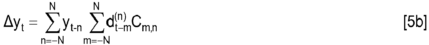
- this term is a digital linear filter with input d t n and impulse response c m,n . So, ⁇ x t and ⁇ y t can be computed as the weighted sum of 2N+1 linear filters outputs. This is advantageous because FIR filters can be efficiently implemented in frequency domain, as it will be discussed in detail herein after.
- the outputs of the FIR filters with positive values of index n may be easily obtained from the outputs of the FIR filters with negative n, with a delay and a conjugation. This advantageously reduces the number of FIR filters needed from 2N+1 to N+1 only.
- Figure 1 schematically shows an apparatus 1 for compensating fiber nonlinearities according to a first embodiment of the present invention, which estimates the perturbation term [ ⁇ x t , ⁇ y t ] T by implementing equations [5a], [5b].
- the apparatus 1 may be implemented either at an optical transmitter (where it pre-compensate fiber nonlinearities before they occur) or at an optical coherent receiver (where it compensate fiber nonlinearities after they have occurred).
- the apparatus 1 preferably comprises a cascade of a first circuit 2, a second circuit 3 and a third circuit 4.
- the first circuit 2 preferably comprises at least two memory circuits.
- the first memory circuit is suitable for storing the digitalized and normalized complex amplitudes x t-N , x t-N+1 ..., x t-2 , x t-1 , x t of a block of consecutive symbols carried by the polarization x, while a second memory circuit is suitable for storing the digitalized and normalized complex amplitudes y t-N , y t-N+1 ..., y t-2 , y t-1 , y t of a block of consecutive symbols carried by the polarization y.
- the second circuit 3 preferably comprises N+1 linear filters 30, 31, 32 ..., 3N, each linear filter 30, 31, 32 ..., 3N being configured to receive and linearly filter a respective sequence of samples d t 0 , d t 1 , d t 2 , ... d t N according to equation [8].
- each linear filter 30, 31, 32 ..., 3N has a filter length 2N+1.
- Each linear filter 30, 31, 32 ..., 3N is preferably implemented in the frequency domain, namely it is implemented as a cascade of a FFT (Fast Fourier Transform) block, a multiplier and an inverse FFT block. This allows reducing the complexity of each single filter, and then of the whole second circuit 3 (and, ultimately, of the whole apparatus 1), as it will be discussed in detail herein after.
- FFT Fast Fourier Transform
- the two weighted sums differ in the weights, which are the symbols x t originally received on polarization x for ⁇ x t (equation [9a]) and the symbols y t originally received on polarization y for ⁇ y t (equation [9b]).
- the third circuit 4 is capable of computing these summations starting from only N+1 terms o t 0 , o t 1 , o t 2 , ... o t N received from the second circuit 2.
- the apparatus 1 finally comprise due adders 51, 52 which subtract the perturbation term [ ⁇ x t , ⁇ y t ] T calculated for each pair of symbols x t , y t at the time t from the complex amplitudes of the symbols themselves, so as to provide a pair of compensated symbols x t C , y t C .
- the complexity of the apparatus 1 according to the first embodiment of the present invention is advantageously much lower than the complexity of a known circuit calculating the perturbation term [ ⁇ x t , ⁇ y t ] T by plainly implementing equations [2a], [2b].
- the overall complexity C1 of the apparatus 1 is indeed equal to C2+C3+C4, wherein C2 is the complexity of the first circuit 2, C3 is the complexity of the second linear circuit 3 and C4 is the complexity of the third circuit 4.
- the complexities C2 and C4 scale with the number of parallel filters in the first circuit 2, and is thus O(N).
- the complexity C3 of the linear circuit 3 is (N+1)log 2 (2N) ⁇ 770. Considering that C3 is the major contributor to the overall circuit complexity, the number of operations per sample is therefore reduced by orders of magnitude.
- the apparatus 1 according to the first embodiment of the present invention is much less complex than a circuit calculating the perturbation term [ ⁇ x t , ⁇ y t ] T by plainly implementing equations [2a], [2b]. Hence, it may be practically implemented at either an optical transmitter or an optical coherent receiver, as it will be described in detail herein after.
- the inventors have noticed that the complexity C3 of the linear circuit 3 (and hence of the whole apparatus 1) may be further reduced.
- the values shown in Figure 2 are normalized relative to the value of C 0,0 and are represented in logarithmic scale. It can be seen that for large
- K (which will be termed herein after also “domain restriction parameter") being an integer number lower than N.
- Equation [10] basically defines in the n,m plane a cross-shaped domain restriction which is schematically depicted in Figure 3(a) .
- the perturbation term [ ⁇ x t , ⁇ y t ] T may be therefore advantageously computed using 4K+4 linear filters instead of N+1.
- K ⁇ N the complexity of the linear circuit 2 may be accordingly particularly reduced, as it will be discussed in detail herein after.
- Figure 4 schematically shows an apparatus 1' for compensating fiber nonlinearities according to a second embodiment of the present invention, which estimates the perturbation term [ ⁇ x t , ⁇ y t ] T by implementing equations [12a], [12b].
- the apparatus 1' may be implemented either at an optical transmitter (where it pre-compensate fiber nonlinearities before they occur) or at an optical coherent receiver (where it compensate fiber nonlinearities after they have occurred).
- the apparatus 1' preferably comprises a cascade of a first circuit 2', a second circuit 3' and a third circuit 4'.
- the first circuit 2' preferably comprises memory circuits.
- the first memory circuit is suitable for storing the digitalized and normalized complex amplitudes x t-K , x t-K+1 ..., x t-2 , x t-1 , x t of a block of consecutive symbols carried by the polarization x, while a second memory circuit is suitable for storing the digitalized and normalized complex amplitudes y t-K , y t-K+1 ..., y t-2 , y t-1 , y t of a block of consecutive symbols carried by the polarization y.
- Each linear filter 310, 320, 330, 340 ... 31 K, 32K, 33K, 34K has a filter length 2N+1.
- Each linear filter 310, 320, 330, 340 ... 31 K, 32K, 33K, 34K is preferably implemented in the frequency domain, namely it is implemented as a cascade of a FFT (Fast Fourier Transform) block, a multiplier and an inverse FFT block. This allows reducing the complexity of each single filter, and then of the whole second circuit 3' (and, ultimately, of the whole apparatus 1), as discussed above.
- FFT Fast Fourier Transform
- the apparatus 1' finally comprise due adders 51', 52' which subtract the perturbation term [ ⁇ x t , ⁇ y t ] T calculated for each pair of symbols x t , y t at the time t from the complex amplitudes of the symbols themselves, so as to provide a pair of compensated symbols x t C , y t C .
- the complexity of the apparatus 1' according to this second embodiment is much lower than the complexity of a known circuit calculating the perturbation term [ ⁇ x t , ⁇ y t ] T by plainly implementing equations [2a], [2b], and even much lower than the complexity of the apparatus 1 shown in Figure 1 .
- the overall complexity C1' of the apparatus 1' is indeed equal to C2'+C3'+C4', wherein C2' is the complexity of the first nonlinear circuit 2', C3' is the complexity of the second linear circuit 3' and C4' is the complexity of the third nonlinear circuit 4'.
- the complexities C2' and C4' scales as O(N).
- the inventors have performed numerical simulations of nonlinear propagation, with a domain restrictive perturbative nonlinear pre-compensation algorithm carried out at the transmitter side.
- the domain restriction parameter K is then preferably comprised between 3 and 10, more preferably between 3 and 5, even more preferably it is equal to 4.
- the apparatuses 1 and 1' according to the first and second embodiments of the present invention are both much less complex than a circuit calculating the perturbation term [ ⁇ x t , ⁇ y t ] T by plainly implementing equations [2a], [2b]. Hence, they may be practically implemented at either an optical transmitter or an optical coherent receiver, as it will be described in detail herein after with reference to Figures 6a and 6b .
- Figure 6a in particular shows an optical transmitter TX comprising an encoding block, a symbol mapping block, a nonlinear equalizer, a digital to analog converter (DAC) and a mapper.
- TX comprising an encoding block, a symbol mapping block, a nonlinear equalizer, a digital to analog converter (DAC) and a mapper.
- DAC digital to analog converter
- the encoding block receives two sequences of bits to be transmitted (one per each polarization component x, y) and encodes them, e.g. using a FEC coding algorithm.
- the symbol mapping block maps each pattern of m encoded bits into a corresponding symbol having a certain complex amplitude.
- the nonlinear equalizer preferably comprises the apparatus 1 or the apparatus 1'.
- the nonlinear equalizer preferably calculates a perturbation term [ ⁇ x t , ⁇ y t ] T for each pair of symbols on the two polarization components x, y as described above and subtracts it from their complex amplitudes. This allows implementing a pre-compensation of the nonlinear distortions which the pulses carrying those symbols on the two polarizations x, y will undergo during propagation.
- Pre-compensating the nonlinear distortion which each pulse will undergo during propagation along the optical link advantageously allows calculating the perturbation term [ ⁇ x t , ⁇ y t ] T in absence of ASE (Amplified Spontaneous Emission) noise. The calculation is accordingly more accurate.
- the DAC converts the pre-compensated complex amplitudes of the two symbols into an analog electric signal.
- the modulator uses the analog, pre-compensated complex amplitudes of the two symbols for modulating the optical carrier on its two polarization components x, y.
- the optical signal output by the transmitter TX therefore carries two sequences of symbols as two sequences of pulses, one per each polarization component x, y.
- Figure 6b shows an optical coherent receiver RX comprising an optical front end, an analog to digital converter (ADC), a linear equalizer, a demodulator, a nonlinear equalizer and a decoder.
- ADC analog to digital converter
- the optical front end receives the optical signal carrying two sequences of symbols as two sequences of pulses on its two polarization components x, y and converts it into two electrical signals.
- the ADC converts the electrical signals in a digital format.
- the linear equalizer preferably compensates the distortion which the optical signal undergoes due to linear effects (chromatic dispersion, PMD, etc.) occurring during its propagation along the optical link.
- the demodulator recovers the complex amplitude of each pulse of the compensated electrical signals.
- the nonlinear equalizer preferably comprises the apparatus 1 or the apparatus 1'.
- the nonlinear equalizer preferably calculates a perturbation term [ ⁇ x t , ⁇ y t ] T for each pair of pulses on the two polarization components x, y as described above, and subtracts it from their complex amplitudes.
- Implementing the nonlinear equalizer after the demodulator advantageously allows calculating the perturbation term [ ⁇ x t , ⁇ y t ] T at one sample per symbol.
- the perturbation term [ ⁇ x t , ⁇ y t ] T calculated for each pair of pulses is subtracted from the complex amplitudes of the pulses before FEC decoding performed by the decoder.
- the perturbation term [ ⁇ x t , ⁇ y t ] T is directly input to the decoder, which uses it in the computation of the symbol Log-Likelihood Ratio (LLR).
- any functional blocks referred to as “device”, “unit”, “block”, “module”, “circuit” or “processing unit” may be provided through the use of dedicated hardware as well as hardware capable of executing software in association with appropriate software.
- the functions may be provided by a single dedicated processor, by a single shared processor, or by a plurality of individual processors, some of which may be shared.
- processing unit should not be construed to refer exclusively to hardware capable of executing software, and may implicitly include, without limitation, digital signal processor (DSP) hardware, network processor, application specific integrated circuit (ASIC), field programmable gate array (FPGA), read only memory (ROM) for storing software, random access memory (RAM), and non volatile storage.
- DSP digital signal processor
- ASIC application specific integrated circuit
- FPGA field programmable gate array
- ROM read only memory
- RAM random access memory
- non volatile storage Other hardware, conventional and/or custom, may also be included.
Landscapes
- Physics & Mathematics (AREA)
- Nonlinear Science (AREA)
- Electromagnetism (AREA)
- Engineering & Computer Science (AREA)
- Computer Networks & Wireless Communication (AREA)
- Signal Processing (AREA)
- Optical Communication System (AREA)
Abstract
Description
- The present invention relates to the field of optical communication networks. More particularly, the present invention relates to the compensation, at a transmitter or coherent optical receiver for optical communication networks, of distortions induced on optical signals by fiber nonlinearities.
- As known, in optical communication networks digital data are transmitted along optical fiber links in the form of optical signals with modulated amplitude and/or phase. For instance, in QPSK (Quadrature Phase Shift Keying) the phase is modulated, whereas in QAM (Quadrature Amplitude Modulation) both amplitude and phase are modulated.
- A modulation format is typically defined by a constellation, namely a set of M symbols which may be represented as M points in a complex plane (or I-Q plane). Each symbol has a certain complex amplitude (phase and modulus) and is associated with a respective label of m=log2(M) bits. At the transmitter, each pattern of m bits of the digital data to be transmitted is mapped into the symbol whose label matches the m bits of the pattern. Then, the symbol complex amplitude is used for modulating an optical carrier for a symbol time τ. A modulated optical signal is then typically in the form of a sequence of pulses of duration τ, each pulse carrying a respective symbol and having a respective normalized complex amplitude. On the other hand, at the receiver side the normalized complex amplitude of each pulse of the received modulated optical signal is recovered and demapped into a corresponding label of m bits.
- Polarization multiplexing modulation schemes are also known, such as PM-QPSK (Polarization-Multiplexed QPSK) or PM-QAM (Polarization-Multiplexed QAM), which provide for transmitting digital data using two polarization components x and y of a same optical signal. Each polarization component carries a respective sequence of symbols.
- In an intra-dyne polarization diversity coherent receiver, the incoming polarization-multiplexed optical signal is mixed by means of a polarization and phase diversity optical front-end with the signal emitted by a local laser. The optical front-end recovers the polarization components x and y of the received optical signal. These recovered components basically correspond to the polarization components of the optical signal as originally transmitted, except for noise and distortions introduced by propagation along the optical link and/or by processing of the received optical signal at the receiver itself. Then, the recovered polarization components are converted into corresponding electric analog signals and then into corresponding digital signals (one per each polarization x and y) by an ADC (Analog to Digital Converter). The digital signals are then digitally processed for channel equalization and finally demodulated.
- Channel equalization typically compensates the distortions introduced by linear effects occurring in the optical link as the polarization-multiplexed optical signal propagates therethrough, such as chromatic dispersion, polarization rotations and polarization mode dispersion (PMD).
- However, as the polarization-multiplexed optical signal propagates, it also undergoes distortions due to nonlinear effects occurring in the optical link, in particular the Kerr effect. As known, the Kerr effect consists in a dependency of the refractive index of the optical mean on the intensity of the optical signal. This dependency results in distortions of the optical signal, such as SPM (Self Phase Modulation), intra-channel XPM (Cross Phase Modulation) and intra-channel FWM (Four Wave Mixing), which alter the normalized complex amplitude of the pulses and accordingly impair demodulation.
- Currently, noise and distortions induced by nonlinear effects are both handled by demodulation and FEC (Forward Error Correction) algorithms, which treat them all as white Gaussian noise. However, differently from noise, distortions due to fiber nonlinearities are predictable based on known equations. Therefore, in principle they may be estimated and compensated at the receiver, or even pre-compensated at the transmitter.
- Theoretical approaches are known for compensating fiber nonlinearities, which start from the assumption that propagation of optical signals in an optical fiber at the presence of nonlinearities is governed by the Non Linear Schroedinger Equation (NLSE):

- One of these approaches is based on the known "back-propagation" algorithm, which however exhibits a high complexity and is accordingly not suitable for a practical implementation at the transmitter or receiver of an optical communication network.
- Z. Tao et al., "Complexity-reduced digital nonlinear compensation for coherent optical system", Proc. Next-Generation Optical Communication: Components, Sub-Systems, and Systems II (SPIE 2013), Vol. 8647, 86470k-1, 5 February 2013 describes a digital nonlinear compensation having a complexity reduced in comparison to back propagation, which makes use of a perturbation analysis. According to the perturbation analysis, an arbitrary section of an optical link with chromatic dispersion and nonlinearities has a corresponding perturbation model whereby nonlinearity on the two polarizations x and y is modelled as an additive perturbation term [Δux, Δuy]T, whereas chromatic dispersion is concentrated on lumped chromatic dispersion blocks. Under the assumption of large chromatic dispersion and Gaussian input pulse, the additive perturbation term [Δux, Δuy]T is:


- β 2 is the group velocity dispersion;
- γ is the nonlinear coefficient;
- r is the pulse width;
- T is the inverse of the pulse rate;
- Leff is the effective length;
- L is the transmission distance; and
- E1(·) is the exponential integral function.
- The nonlinear coefficient C0,0 corresponds to the SPM, the coefficients Cm,0 and C0,n correspond to the intra-channel XPM and the coefficients Cm,n (with m≠0, n≠0) correspond to the intra-channel FWM.
- Further, the nonlinear coefficients Cm,n have the following two properties:


- The perturbation term calculated according to equations [2a], [2b] includes two dimensional summations of three product terms and it therefore quite complex. The circuit implementing the above equations [2a], [2b] e.g. as a pre-compensation at the transmitter comprises two perturbation calculation blocks, a look up table and two adders. The look up table stores the values of the nonlinear coefficients Cm,n, which are pre-calculated according to the above equations [3a], [3b], [3c]. Each perturbation calculation block receives two inputs, namely the pulse sequence carried by the polarization component x and the pulse sequence carried by the polarization component y. Then, each perturbation calculation block uses the received pulse sequences and the nonlinear coefficients Cm,n retrieved from the lookup table in order to calculate the perturbation term [Δux, Δuy]T according to equations [2a], [2b]. The adders then subtract the calculated perturbation term [Δux, Δuy]T from the pulse sequences carried by the polarization components x, y.
- Though in principle, according to the perturbation theory, in the two dimensional summations of the above equations [2a], [2b] the pulse indexes n and m should run from -∞ to +∞, the two dimensional summations may be truncated to n, m=-N, ...N, N being a finite integer number. The complexity (namely, the number of operations per symbol) of the above circuit implementing the above equations [2a], [2b] as described above therefore mainly depends on the number N, and scales as O((2N)2).
- A value of e.g. N=100 induces negligible penalties on the accuracy of the perturbation term [Δux, Δuy]T estimated using equations [2a], [2b]. However, with N=100 the complexity of the circuit is still very high, since (2N)2=40.000 operations per symbol are required. This complexity is orders of magnitude larger than the complexity of the other digital blocks of a transmitter or receiver (e.g. of the linear equalizer of the receiver). The physical implementation of a circuit compensating fiber nonlinearities by plainly implementing the above equations [2a], [2b] is therefore prohibitive. On the other hand, reducing N in order to reduce complexity to a lower degree allowing physical implementation of the circuit leads to significant penalties on the accuracy of the estimated perturbation term [Δux, Δuy]T.
- In view of the above, it is an object of the present invention to provide an apparatus and a method for compensating, at a transmitter or at a coherent optical receiver, the distortions induced by fiber nonlinearities, whose complexity is much reduced in comparison to the above known circuit and which, at the same time, substantially does not introduce performance penalties.
- In the present description and in the claims, the expression "nonlinear operation on pulses complex amplitudes" will designate an operation comprising at least one multiplication between two complex amplitudes of either a same pulse sequence (for example


- According to a first aspect, the present invention provides an apparatus for compensating nonlinear distortions induced on an optical signal during propagation along an optical link, the apparatus comprising a cascade of:
- (i) a first circuit configured to receive a sequence of first complex amplitudes xt of consecutive pulses carried by a first polarization component x of the optical signal, the first circuit being configured to calculate a number of sequences of samples by carrying out at least one nonlinear operation on the first complex amplitudes xt;
- (ii) a second circuit comprising a number of linear filters configured to receive and linearly filter the number of sequences of samples so as to provide a number of corresponding sequences of linearly filtered samples;
- (iii) a third circuit configured to calculate a sequence of first polarization components Δxt of a perturbation nonlinear term [Δxt, Δyt]T as a first weighted sum of the number of sequences of linearly filtered samples by using the first complex amplitudes xt as weights of the first weighted sum; and
- (iv) at least one adder configured to compensate the nonlinear distortions by subtracting the sequence of first polarization components Δxt of the perturbation nonlinear term [Δxt, Δyt]T from the sequence of first complex amplitudes xt.
- Preferably, in the apparatus:
- the first circuit is further configured to receive a sequence of second complex amplitudes yt of consecutive pulses carried by a second polarization component (y) of the optical signal, the first circuit being configured to calculate the number of sequences of samples by carrying out the at least one nonlinear operation on the first complex amplitudes xt and on the second complex amplitudes yt;
- the third circuit is further configured to calculate a sequence of second polarization components Δyt of the perturbation nonlinear term [Δxt, Δyt]T as a second weighted sum of the number of sequences of linearly filtered samples by using the second complex amplitudes yt as weights of the second weighted sum; and
- the at least one adder is further configured to compensate the nonlinear distortions by subtracting the sequence of second polarization components Δyt of the perturbation nonlinear term [Δxt, Δyt]T from the sequence of second complex amplitudes yt.
- According to a first embodiment, the first circuit is configured to calculate N+1 sequences of samples


- Preferably, N is comprised between 80 and 120, more preferably is equal to 100.
- Preferably, second circuit comprises N+1 linear filters configured to receive the N+1 sequences of samples


- Preferably, the third circuit is configured to calculate the sequence of first polarization components Δxt of the perturbation nonlinear term [Δxt, Δyt]T and the second polarization components Δyt of the perturbation nonlinear term [Δxt, Δyt]T as:


- According to a second embodiment, the first circuit is configured to calculate 4K+4 sequences of samples


- Preferably, K is comprised between 3 and 10
- Preferably, the second circuit comprises 4K+4 linear filters configured to receive the sequences of samples


- Preferably, the third circuit is configured to calculate the sequence of first polarization components Δxt of the perturbation nonlinear term [Δxt, Δyt]T and the second polarization components Δyt of the perturbation nonlinear term [Δxt, Δyt]T as:


- Preferably, each one of the number of linear filters is a FIR filter implemented in the frequency domain as a cascade of an FFT block, a multiplier and an IFFT block.
- According to a second aspect, the present invention provides a transmitter for an optical coherent transmission system comprising an apparatus for compensating nonlinear distortions as set forth above.
- According to a third aspect, the present invention provides a receiver for an optical coherent transmission system comprising an apparatus for compensating nonlinear distortions as set forth above.
- According to a fourth aspect, the present invention provides a method for compensating nonlinear distortions induced on an optical signal during propagation along an optical link, the method comprising:
- (i) receiving a sequence of first complex amplitudes xt of consecutive pulses carried by a first polarization component x of the optical signal, and calculating a number of sequences of samples by carrying out at least one nonlinear operation on the first complex amplitudes xt;
- (ii) receive and linearly filter the number of sequences of samples so as to provide a number of corresponding sequences of linearly filtered samples;
- (iii) calculating a sequence of first polarization components Δxt of a perturbation nonlinear term [Δxt, Δyt]T as a first weighted sum of the number of sequences of linearly filtered samples by using the first complex amplitudes xt as weights of the first weighted sum; and
- (iv) compensating the nonlinear distortions by subtracting the sequence of first polarization components Δxt of the perturbation nonlinear term [Δxt, Δyt]T from the sequence of first complex amplitudes xt.
- According to a fourth aspect, the present invention provides a computer program product comprising computer-executable instructions for performing, when the program is run on a computer, the steps of the method set forth above.
- The present invention will become clearer by reading the following detailed description, given by way of example and not of limitation, to be read by referring to the accompanying drawings, wherein:
-
Figure 1 schematically shows an apparatus for compensating fiber nonlinearities according to a first embodiment of the present invention; -
Figure 2 is a diagram of the values of the nonlinear coefficients Cm,n as a function of the pulse indexes n, m; -
Figure 3 schematically shows two different domain restrictions operated on the nonlinear coefficients Cm,n, according to preferred variants of the present invention; -
Figure 4 schematically shows an apparatus for compensating fiber nonlinearities according to a second embodiment of the present invention; -
Figure 5 is a diagram showing the gain of Q-factor as a function of the domain restriction parameter K; and -
Figures 6a and 6b show an optical transmitter and an optical coherent receiver, respectively, including an apparatus for compensating fiber nonlinearities according to embodiments of the present invention. - Equations [2a], [2b] providing the additive perturbation term [Δux, Δuy]T on the two polarizations x and y may be written to include for time dependency:


- It shall be noticed that the same term


- Moreover, since as mentioned above Cm,n = -Cm,n* and


- Further, since the FIR filters are time invariant,


- In other words, the outputs of the FIR filters with positive values of index n may be easily obtained from the outputs of the FIR filters with negative n, with a delay and a conjugation. This advantageously reduces the number of FIR filters needed from 2N+1 to N+1 only.
-
Figure 1 schematically shows anapparatus 1 for compensating fiber nonlinearities according to a first embodiment of the present invention, which estimates the perturbation term [Δxt, Δyt]T by implementing equations [5a], [5b]. - As it will be discussed in detail herein after, the
apparatus 1 may be implemented either at an optical transmitter (where it pre-compensate fiber nonlinearities before they occur) or at an optical coherent receiver (where it compensate fiber nonlinearities after they have occurred). - The
apparatus 1 preferably comprises a cascade of afirst circuit 2, asecond circuit 3 and athird circuit 4. - The
first circuit 2 is configured to receive two sequences of symbols xt, yt (one sequence per each polarization component x, y) and to process them to calculate N+1 sequences of samples
- In particular, the
first circuit 2 preferably comprises at least two memory circuits. The first memory circuit is suitable for storing the digitalized and normalized complex amplitudes xt-N, xt-N+1 ..., xt-2, xt-1, xt of a block of consecutive symbols carried by the polarization x, while a second memory circuit is suitable for storing the digitalized and normalized complex amplitudes yt-N, yt-N+1 ..., yt-2, yt-1, yt of a block of consecutive symbols carried by the polarization y. - The
first circuit 2 then comprises a plurality of adders, multipliers and complex conjugate elements which combine the content of the memory circuits so as to provide N+1 sequences of samples


- The
second circuit 3 preferably is a linear circuit suitable for receiving the N+1 sequences of samples


- In particular, the
second circuit 3 preferably comprises N+1linear filters linear filter samples 
linear filter 

- Each
linear filter linear filter length 2N+ 1. Eachlinear filter - The
third circuit 4 preferably is configured to implement two different weighted sums of the filter outputs


- The two weighted sums differ in the weights, which are the symbols xt originally received on polarization x for Δxt (equation [9a]) and the symbols yt originally received on polarization y for Δyt (equation [9b]).
- It may be noticed that - though the summations of equations [9a] and [9b] implemented by the
third circuit 4 comprise 2N+1 terms (since n ranges from -N to N), thethird circuit 4 is capable of computing these summations starting from only N+1terms 
second circuit 2. As mentioned above, the other N terms


- The
apparatus 1 finally comprisedue adders - The complexity of the
apparatus 1 according to the first embodiment of the present invention is advantageously much lower than the complexity of a known circuit calculating the perturbation term [Δxt, Δyt]T by plainly implementing equations [2a], [2b]. - The overall complexity C1 of the
apparatus 1 is indeed equal to C2+C3+C4, wherein C2 is the complexity of thefirst circuit 2, C3 is the complexity of the secondlinear circuit 3 and C4 is the complexity of thethird circuit 4. The complexities C2 and C4 scale with the number of parallel filters in thefirst circuit 2, and is thus O(N). As to C3, as mentioned above, thelinear circuit 3 comprises N+1linear filters - Assuming e.g. N=100 (which, as discussed above, is a value inducing negligible penalties on the accuracy of the perturbation term due to truncation of the double running summations of equations [2a], [2b]), the known circuit implementing equations [2a], [2b] has a complexity which scales as O((2N)2), thus for N= 100 this equal to 40.000. For the same value of N, the complexity C3 of the
linear circuit 3 is (N+1)log2(2N) ≅ 770. Considering that C3 is the major contributor to the overall circuit complexity, the number of operations per sample is therefore reduced by orders of magnitude. - Hence, the
apparatus 1 according to the first embodiment of the present invention is much less complex than a circuit calculating the perturbation term [Δxt, Δyt]T by plainly implementing equations [2a], [2b]. Hence, it may be practically implemented at either an optical transmitter or an optical coherent receiver, as it will be described in detail herein after. - Furthermore, advantageously, no penalties are introduced in the estimation of the perturbation term [Δxt, Δyt]T, because equations [5a], [5b] are directly derived from equations [2a], [2b] by means of simple algebraic passages, without introducing any approximation.
- The inventors have noticed that the complexity C3 of the linear circuit 3 (and hence of the whole apparatus 1) may be further reduced.
- The inventors have indeed noticed that in the summations of equations [4a], [4b] not all the terms provide a significant contribution, because the values of the nonlinear coefficients Cm,n depend on the values of the pulse indexes m,n.
-
Figure 2 shows a contour plot of exemplary values of the nonlinear coefficients Cm,n for a typical optical link, as a function of the pulse indexes n, m with N=100, β 2 =20 ps2/km, γ =1.3 (WKm)-1, T=30 ps, Leff = 20 km and L=1500 km. The values shown inFigure 2 are normalized relative to the value of C0,0 and are represented in logarithmic scale. It can be seen that for large |nm|, i.e. far from the axes n=0 and m=0, the nonlinear coefficients Cm,n have close to zero value. As a consequence, their contribute to the above sums can be discarded without effects. - More particularly, according to advantageous variants, the nonlinear coefficients Cm,n (n,m=-N, ... N) are subjected to a domain restriction, meaning that a certain area is identified in the n,m plane, which comprises the nonlinear coefficients Cm,n whose value is less significant and is accordingly set equal to zero. Since, as discussed above, the nonlinear coefficients Cm,n decrease from C0,0 as the distance from the axes n=0, m=0 increases, according to an advantageous variant the domain restriction is defined as follows:

- K (which will be termed herein after also "domain restriction parameter") being an integer number lower than N.
- Equation [10] basically defines in the n,m plane a cross-shaped domain restriction which is schematically depicted in
Figure 3(a) . The black areas comprise the values of n, m fulfilling the condition set by equation [10], under the assumption that K=4. The nonlinear coefficients Cm,n whose pulse indexes n, m fulfil equation [10] are then set equal to zero, meaning that the summations of equations [4a], [4b] are truncated at n, m=-K ...K. Equation [10] is not limiting, since other domain restrictions are possible.Figure 3(b) shows a further exemplary domain restriction, wherein the boundaries between the areas comprising the less significant nonlinear coefficients and the area close to the axes n=0, m=0 which comprises the more significant coefficients are more refined than inFigure 3(a) . - Referring again to
Figure 3(a) , equations [4a], [4b] with the truncation to n, m=-K, ... K may be rewritten as follows:

- Equations [11 a], [11 b] may be further rewritten as follows:


- Under these assumptions, the perturbation term [Δxt, Δyt]T may be therefore advantageously computed using 4K+4 linear filters instead of N+1. By choosing K<<N, the complexity of the
linear circuit 2 may be accordingly particularly reduced, as it will be discussed in detail herein after. -
Figure 4 schematically shows an apparatus 1' for compensating fiber nonlinearities according to a second embodiment of the present invention, which estimates the perturbation term [Δxt, Δyt]T by implementing equations [12a], [12b]. - As it will be discussed in detail herein after, also the apparatus 1' may be implemented either at an optical transmitter (where it pre-compensate fiber nonlinearities before they occur) or at an optical coherent receiver (where it compensate fiber nonlinearities after they have occurred).
- Similarly to the
apparatus 1 shown inFigure 1 , the apparatus 1' preferably comprises a cascade of a first circuit 2', a second circuit 3' and a third circuit 4'. - Under the domain restriction condition of equation [10], the first circuit 2' is a nonlinear circuit configured to receive two sequences of symbols xt, yt (one sequence per each polarization x, y) and to process them to calculate 4K+4 sequences of samples


- In particular, the first circuit 2' preferably comprises memory circuits. The first memory circuit is suitable for storing the digitalized and normalized complex amplitudes xt-K, xt-K+1 ..., xt-2, xt-1, xt of a block of consecutive symbols carried by the polarization x, while a second memory circuit is suitable for storing the digitalized and normalized complex amplitudes yt-K, yt-K+1 ..., yt-2, yt-1, yt of a block of consecutive symbols carried by the polarization y.
- The first circuit 2' then comprises a plurality of adders, multipliers and complex conjugate elements which combine the content of the memory circuits so as to provide 4K+4 sequences of samples


- The second circuit 3' preferably is a linear circuit suitable for receiving the 4K+4 sequences of samples


- In particular, the second circuit 3' preferably comprises 4K+4
linear filters 


- Each
linear filter length 2N+ 1. Eachlinear filter - The third circuit 4' preferably is a nonlinear circuit configured to implement a weighted sum of the filter outputs


- It may be noticed that - though the sums of equation [15a] and [15b] implemented by the third circuit 4' comprise 8K+4 terms (since n ranges from -K to K) - the third circuit 4' is capable of computing these summations starting from only 4K+4 terms


- The apparatus 1' finally comprise due adders 51', 52' which subtract the perturbation term [Δxt, Δyt]T calculated for each pair of symbols xt, yt at the time t from the complex amplitudes of the symbols themselves, so as to provide a pair of compensated symbols xt C, yt C.
- The complexity of the apparatus 1' according to this second embodiment is much lower than the complexity of a known circuit calculating the perturbation term [Δxt, Δyt]T by plainly implementing equations [2a], [2b], and even much lower than the complexity of the
apparatus 1 shown inFigure 1 . - The overall complexity C1' of the apparatus 1' is indeed equal to C2'+C3'+C4', wherein C2' is the complexity of the first nonlinear circuit 2', C3' is the complexity of the second linear circuit 3' and C4' is the complexity of the third nonlinear circuit 4'. The complexities C2' and C4' scales as O(N). As to C3', as mentioned above the linear circuit 3' comprises 4K+4 linear filters, each filter having length L=2N+1. Assuming that each filter is implemented in the frequency domain as explained above, the complexity of each single linear filter scales as O(logN).
- Assuming e.g. N=100 (which, as discussed above, is a value inducing negligible penalties on the accuracy of the perturbation term due to truncation of the double running summations of equations [2a], [2b]) and assuming e.g. K=4, the complexity C3' of the linear circuit 3' is (4K+4)(log22N)≅150, which is two orders of magnitude lower than the complexity of a known circuit plainly implementing equations [2a], [2b].
- It may also be noticed that, due to symmetries evident from algebraic inspection, the term with n=0 can be realized with 2 filters instead of 4, meaning that according to a particularly preferred variant the circuit 3' comprises 4K+2 filters, instead of 4K+4. The complexity C3' according to this variant is accordingly (4K+2)(log22N). With N=100 and K=4, the complexity C3' is accordingly (4K+2)(log22N)≅137.
- Furthermore, advantageously, the domain restriction parameter K may be selected so as to minimize the penalties which the further truncation of the summations in equations [2a], [2b] to n,m=-K, ... K induces on the estimation of the nonlinear term [Δxt, Δyt]T.
- In particular, the inventors have performed numerical simulations of nonlinear propagation, with a domain restrictive perturbative nonlinear pre-compensation algorithm carried out at the transmitter side. A 3-
channel 32 GBaud PDM-16QAM WDM transmission over 20 spans of standard SMF fiber has been simulated (β 2 =20 ps2/km, γ =1.3 (WKm)-1, T=30 ps, Leff = 20 km and L=1500 km). - In order to model fiber nonlinearity, a standard split-step Fourier method has been used. The Q-factor (which as known is a measure of the optical signal to noise ratio and is related to the BER as BER = 1/2erfc(Q/sqrt(2)) has been calculated in two scenarios, namely (i) without fiber nonlinearities compensation and (ii) with fiber nonlinearities pre-compensation based on the above perturbation theory. Then, the gain of Q-factor due to application of the fiber nonlinearities pre-compensation has been calculated. The domain restriction was based on the above equation [10] (cross-shaped domain restriction), and the gain of Q-factor has been calculated for K=1, 2, ... 10. Also the gain in case of fiber nonlinearities pre-compensation without domain restriction has been calculated, and was found to be ≈ 0.7.
- The graph of
Figure 5 shows the calculated gain of Q-factor vs K. It may be appreciated from the graph that the gain of Q-factor firstly increases as K increases, and then reaches a sort of plateau in the range K=4 to K=10. In this plateau, the gain of Q-factor is of 0.65-0.7 dB about, namely it is as high as the domain unrestricted case. Hence, a value of K=4 basically provides the same gain of Q-factor as the unrestricted case and, at the same time, allows minimizing the complexity of the apparatus which calculates the perturbation term [Δxt, Δyt]T. The domain restriction parameter K is then preferably comprised between 3 and 10, more preferably between 3 and 5, even more preferably it is equal to 4. - As discussed above, the
apparatuses 1 and 1' according to the first and second embodiments of the present invention are both much less complex than a circuit calculating the perturbation term [Δxt, Δyt]T by plainly implementing equations [2a], [2b]. Hence, they may be practically implemented at either an optical transmitter or an optical coherent receiver, as it will be described in detail herein after with reference toFigures 6a and 6b . -
Figure 6a in particular shows an optical transmitter TX comprising an encoding block, a symbol mapping block, a nonlinear equalizer, a digital to analog converter (DAC) and a mapper. - The encoding block receives two sequences of bits to be transmitted (one per each polarization component x, y) and encodes them, e.g. using a FEC coding algorithm.
- For each polarization component x, y, the symbol mapping block maps each pattern of m encoded bits into a corresponding symbol having a certain complex amplitude.
- The nonlinear equalizer preferably comprises the
apparatus 1 or the apparatus 1'. In particular, the nonlinear equalizer preferably calculates a perturbation term [Δxt, Δyt]T for each pair of symbols on the two polarization components x, y as described above and subtracts it from their complex amplitudes. This allows implementing a pre-compensation of the nonlinear distortions which the pulses carrying those symbols on the two polarizations x, y will undergo during propagation. Pre-compensating the nonlinear distortion which each pulse will undergo during propagation along the optical link advantageously allows calculating the perturbation term [Δxt, Δyt]T in absence of ASE (Amplified Spontaneous Emission) noise. The calculation is accordingly more accurate. - The DAC converts the pre-compensated complex amplitudes of the two symbols into an analog electric signal. The modulator uses the analog, pre-compensated complex amplitudes of the two symbols for modulating the optical carrier on its two polarization components x, y. The optical signal output by the transmitter TX therefore carries two sequences of symbols as two sequences of pulses, one per each polarization component x, y.
-
Figure 6b shows an optical coherent receiver RX comprising an optical front end, an analog to digital converter (ADC), a linear equalizer, a demodulator, a nonlinear equalizer and a decoder. - The optical front end receives the optical signal carrying two sequences of symbols as two sequences of pulses on its two polarization components x, y and converts it into two electrical signals. The ADC converts the electrical signals in a digital format.
- The linear equalizer preferably compensates the distortion which the optical signal undergoes due to linear effects (chromatic dispersion, PMD, etc.) occurring during its propagation along the optical link. The demodulator recovers the complex amplitude of each pulse of the compensated electrical signals.
- The nonlinear equalizer preferably comprises the
apparatus 1 or the apparatus 1'. In particular, the nonlinear equalizer preferably calculates a perturbation term [Δxt, Δyt]T for each pair of pulses on the two polarization components x, y as described above, and subtracts it from their complex amplitudes. Implementing the nonlinear equalizer after the demodulator advantageously allows calculating the perturbation term [Δxt, Δyt]T at one sample per symbol. - Then, in case of hard-decision FEC decoding, the perturbation term [Δxt, Δyt]T calculated for each pair of pulses is subtracted from the complex amplitudes of the pulses before FEC decoding performed by the decoder. Otherwise, in case of soft-decision FEC decoding, the perturbation term [Δxt, Δyt]T is directly input to the decoder, which uses it in the computation of the symbol Log-Likelihood Ratio (LLR).
- Even though the above described embodiments relate to a polarization multiplexing modulation schemes, the above principles may be applied also to single polarization modulation schemes, where they also advantageously allow reducing complexity of the circuits comprised in the nonlinear equalizer.
- The functions of the various elements shown in
Figures 1 and4 , including any functional blocks referred to as "device", "unit", "block", "module", "circuit" or "processing unit", may be provided through the use of dedicated hardware as well as hardware capable of executing software in association with appropriate software. When provided by a processor, the functions may be provided by a single dedicated processor, by a single shared processor, or by a plurality of individual processors, some of which may be shared. Moreover, explicit use of the terms "processing unit", "device", "block", "module", "circuit" or "unit" should not be construed to refer exclusively to hardware capable of executing software, and may implicitly include, without limitation, digital signal processor (DSP) hardware, network processor, application specific integrated circuit (ASIC), field programmable gate array (FPGA), read only memory (ROM) for storing software, random access memory (RAM), and non volatile storage. Other hardware, conventional and/or custom, may also be included.
Claims (15)
- An apparatus (1, 1') for compensating nonlinear distortions induced on an optical signal during propagation along an optical link, said apparatus comprising a cascade of:(i) a first circuit (2, 2') configured to receive a sequence of first complex amplitudes xt of consecutive pulses carried by a first polarization component x of said optical signal, said first circuit (2, 2') being configured to calculate a number of sequences of samples
 (ii) a second circuit (3, 3') comprising a number of linear filters (30, 31, ... 3N; 310, 320, 330, 340 ... 31 K, 32K, 33K, 34K) configured to receive and linearly filter said number of sequences of samples
 (iii) a third circuit (4, 4') configured to calculate a sequence of first polarization components Δxt of a perturbation nonlinear term [Δxt, Δyt]T as a first weighted sum of said number of sequences of linearly filtered samples
 (iv) at least one adder (51, 52; 51', 52') configured to compensate said nonlinear distortions by subtracting said sequence of first polarization components Δxt of said perturbation nonlinear term [Δxt, Δyt]T from said sequence of first complex amplitudes xt.
 - An apparatus (1, 1') according to claim 1, wherein:• said first circuit (2, 2') is further configured to receive a sequence of second complex amplitudes yt of consecutive pulses carried by a second polarization component (y) of said optical signal, said first circuit (2, 2') being configured to calculate said number of sequences of samples
 • said third circuit (4, 4') is further configured to calculate a sequence of second polarization components Δyt of said perturbation nonlinear term [Δxt, Δyt]T as a second weighted sum of said number of sequences of linearly filtered samples
 • said at least one adder (51, 52; 51', 52') is further configured to compensate said nonlinear distortions by subtracting said sequence of second polarization components Δyt of said perturbation nonlinear term [Δxt, Δyt]T from said sequence of second complex amplitudes yt.
 - The apparatus (1) according to claim 2, wherein said first circuit (2) is configured to calculate N+1 sequences of samples


where n is an index ranging between 0 and N and N is an integer number. - The apparatus (1) according to claim 3, where N is comprised between 80 and 120.
- The apparatus (1) according to claim 3 or 4, wherein said second circuit (2) comprises N+1 linear filters (30, 31, ... 3N) configured to receive said N+1 sequences of samples


where Cm,n with m=-N... N is the impulse response of said linear filter. - The apparatus (1) according to claim 5, wherein said third circuit (4) is configured to calculate said sequence of first polarization components Δxt of said perturbation nonlinear term [Δxt, Δyt]T and said second polarization components Δyt of said perturbation nonlinear term [Δxt, Δyt]T as:


- The apparatus (1') according to claim 2, wherein said first circuit (2') is configured to calculate 4K+4 sequences of samples


where n is an index ranging between 0 and K and K is an integer number. - The apparatus (1') according to claim 7, wherein K is comprised between 3 and 10.
- The apparatus (1') according to claim 8, wherein said second circuit (3') comprises 4K+4 linear filters (310, 320, 330, 340 ... 31 K, 32K, 33K, 34K) configured to receive said sequences of samples


where Cm,n with m=-N... N are the impulse response of said linear filters. - The apparatus (1) according to claim 9, wherein said third circuit (4') is configured to calculate said sequence of first polarization components Δxt of said perturbation nonlinear term [Δxt, Δyt]T and said second polarization components Δyt of said perturbation nonlinear term [Δxt, Δyt]T as:


- The apparatus (1, 1') according to any of the preceding claims, wherein each one of said number of linear filters is a FIR filter implemented in the frequency domain as a cascade of an FFT block, a multiplier and an IFFT block.
- A transmitter (TX) for an optical coherent transmission system comprising an apparatus for compensating nonlinear distortions according to any of claims 1 to 11.
- A receiver (RX) for an optical coherent transmission system comprising an apparatus for compensating nonlinear distortions according to any of claims 1 to 11.
- A method for compensating nonlinear distortions induced on an optical signal during propagation along an optical link, said method comprising:(i) receiving a sequence of first complex amplitudes xt of consecutive pulses carried by a first polarization component x of said optical signal, and calculating a number of sequences of samples
 (ii) receive and linearly filter said number of sequences of samples

 (iii) calculating a sequence of first polarization components Δxt of a perturbation nonlinear term [Δxt, Δyt]T as a first weighted sum of said number of sequences of linearly filtered samples
 (iv) compensating said nonlinear distortions by subtracting said sequence of first polarization components Δxt of said perturbation nonlinear term [Δxt, Δyt]T from said sequence of first complex amplitudes xt.
 - A computer program product comprising computer-executable instructions for performing, when the program is run on a computer, the steps of the method of claim 14.
Priority Applications (1)
| Application Number | Priority Date | Filing Date | Title |
|---|---|---|---|
| EP15306613.9A EP3157180A1 (en) | 2015-10-13 | 2015-10-13 | Fiber nonlinearities compensation |
Applications Claiming Priority (1)
| Application Number | Priority Date | Filing Date | Title |
|---|---|---|---|
| EP15306613.9A EP3157180A1 (en) | 2015-10-13 | 2015-10-13 | Fiber nonlinearities compensation |
Publications (1)
| Publication Number | Publication Date |
|---|---|
| EP3157180A1 true EP3157180A1 (en) | 2017-04-19 |
Family
ID=54360369
Family Applications (1)
| Application Number | Title | Priority Date | Filing Date |
|---|---|---|---|
| EP15306613.9A Withdrawn EP3157180A1 (en) | 2015-10-13 | 2015-10-13 | Fiber nonlinearities compensation |
Country Status (1)
| Country | Link |
|---|---|
| EP (1) | EP3157180A1 (en) |
Cited By (3)
| Publication number | Priority date | Publication date | Assignee | Title |
|---|---|---|---|---|
| US10756822B1 (en) | 2019-08-27 | 2020-08-25 | Nokia Solutions And Networks Oy | Digital fiber nonlinearity compensation |
| US10887022B2 (en) | 2017-06-15 | 2021-01-05 | Nokia Of America Corporation | Backward propagation with compensation of some nonlinear effects of polarization mode dispersion |
| EP4407895A1 (en) | 2023-01-26 | 2024-07-31 | Nokia Solutions and Networks Oy | Perturbation-based hard-decision nonlinearity compensation |
Citations (2)
| Publication number | Priority date | Publication date | Assignee | Title |
|---|---|---|---|---|
| EP2629471A2 (en) * | 2012-02-20 | 2013-08-21 | Fujitsu Limited | Nonlinear Compensating Apparatus and Method and Transmitter |
| US20150071652A1 (en) * | 2013-09-09 | 2015-03-12 | Ciena Corporation | Methods and systems for reduced complexity nonlinear compensation |
-
2015
- 2015-10-13 EP EP15306613.9A patent/EP3157180A1/en not_active Withdrawn
Patent Citations (2)
| Publication number | Priority date | Publication date | Assignee | Title |
|---|---|---|---|---|
| EP2629471A2 (en) * | 2012-02-20 | 2013-08-21 | Fujitsu Limited | Nonlinear Compensating Apparatus and Method and Transmitter |
| US20150071652A1 (en) * | 2013-09-09 | 2015-03-12 | Ciena Corporation | Methods and systems for reduced complexity nonlinear compensation |
Non-Patent Citations (2)
| Title |
|---|
| EZRA IP: "Complexity reduction algorithms for nonlinear compensation using digital backpropagation", PHOTONICS CONFERENCE (IPC), 2012 IEEE, IEEE, 23 September 2012 (2012-09-23), pages 388 - 389, XP032269123, ISBN: 978-1-4577-0731-5, DOI: 10.1109/IPCON.2012.6358655 * |
| Z. TAO ET AL.: "Complexity-reduced digital nonlinear compensation for coherent optical system", PROC. NEXT-GENERATION OPTICAL COMMUNICATION: COMPONENTS, SUB-SYSTEMS, AND SYSTEMS II (SPIE 2013, vol. 8647, 5 February 2013 (2013-02-05), pages 86470K - 1 |
Cited By (4)
| Publication number | Priority date | Publication date | Assignee | Title |
|---|---|---|---|---|
| US10887022B2 (en) | 2017-06-15 | 2021-01-05 | Nokia Of America Corporation | Backward propagation with compensation of some nonlinear effects of polarization mode dispersion |
| US11356181B2 (en) | 2017-06-15 | 2022-06-07 | Nokia Of America Corporation | Backward propagation with compensation of some nonlinear effects of polarization mode dispersion |
| US10756822B1 (en) | 2019-08-27 | 2020-08-25 | Nokia Solutions And Networks Oy | Digital fiber nonlinearity compensation |
| EP4407895A1 (en) | 2023-01-26 | 2024-07-31 | Nokia Solutions and Networks Oy | Perturbation-based hard-decision nonlinearity compensation |
Similar Documents
| Publication | Publication Date | Title |
|---|---|---|
| Redyuk et al. | Compensation of nonlinear impairments using inverse perturbation theory with reduced complexity | |
| US10637569B2 (en) | Optical transmission characteristic estimation method, optical transmission characteristic compensation method, optical transmission characteristic estimation system and optical transmission characteristic compensation system | |
| US9973277B2 (en) | Reduced complexity nonlinear compensation | |
| US10270537B2 (en) | Method and system for nonlinear interference mitigation | |
| US10193593B2 (en) | Signal processing device, communication system, and signal processing method | |
| US9425900B2 (en) | Chromatic dispersion processing apparatus and method | |
| US20120263454A1 (en) | Crosstalk-Free High-Dimensional Constellations for Dual-Polarized Nonlinear Fiber-Optic Communications | |
| Kumar et al. | Enhanced regular perturbation-based nonlinearity compensation technique for optical transmission systems | |
| EP3352387B1 (en) | Digital multi-channel nonlinearity compensation scheme for optical coherent communication | |
| Xu et al. | Analysis of chromatic dispersion compensation and carrier phase recovery in long-haul optical transmission system influenced by equalization enhanced phase noise | |
| US20170149510A1 (en) | Adaptive Equalizer with Coefficients Determined Using Groups of Symbols to Compensate for Nonlinear Distortions in Optical Fiber Communications | |
| da Silva et al. | Widely linear blind adaptive equalization for transmitter IQ-imbalance/skew compensation in multicarrier systems | |
| US7321734B2 (en) | Digital synthesis of readily compensated optical signals | |
| EP3157180A1 (en) | Fiber nonlinearities compensation | |
| US11356181B2 (en) | Backward propagation with compensation of some nonlinear effects of polarization mode dispersion | |
| JP6355465B2 (en) | Optical receiver, transmitter / receiver, optical communication system, and waveform distortion compensation method | |
| Mohamed et al. | DSP-based dispersion compensation: Survey and simulation | |
| EP3345314B1 (en) | Phase retrieval for compensation of chromatic dispersion-induced inter-symbol interference | |
| Liang et al. | Perturbation-assisted DBP for nonlinear compensation in polarization multiplexed systems | |
| US9515745B2 (en) | Adaptive equalization in coherent receivers using a Stokes space update algorithm | |
| Gao et al. | Electrical post-compensation of intrachannel nonlinearities in 10GBaud coherent QPSK transmission systems | |
| WO2022201763A1 (en) | Light waveform distortion correction method and device, and optical signal reception device | |
| JP7771236B2 (en) | Perturbation-based hard-decision nonlinearity compensation | |
| Li et al. | Antialiased transmitter-side digital backpropagation | |
| WO2023143624A1 (en) | Apparatuses and methods of far-end transmitter skew monitoring in digital subcarrier multiplexing systems |
Legal Events
| Date | Code | Title | Description |
|---|---|---|---|
| PUAI | Public reference made under article 153(3) epc to a published international application that has entered the european phase |
Free format text: ORIGINAL CODE: 0009012 |
|
| STAA | Information on the status of an ep patent application or granted ep patent |
Free format text: STATUS: THE APPLICATION HAS BEEN PUBLISHED |
|
| AK | Designated contracting states |
Kind code of ref document: A1 Designated state(s): AL AT BE BG CH CY CZ DE DK EE ES FI FR GB GR HR HU IE IS IT LI LT LU LV MC MK MT NL NO PL PT RO RS SE SI SK SM TR |
|
| AX | Request for extension of the european patent |
Extension state: BA ME |
|
| STAA | Information on the status of an ep patent application or granted ep patent |
Free format text: STATUS: REQUEST FOR EXAMINATION WAS MADE |
|
| 17P | Request for examination filed |
Effective date: 20171019 |
|
| RBV | Designated contracting states (corrected) |
Designated state(s): AL AT BE BG CH CY CZ DE DK EE ES FI FR GB GR HR HU IE IS IT LI LT LU LV MC MK MT NL NO PL PT RO RS SE SI SK SM TR |
|
| STAA | Information on the status of an ep patent application or granted ep patent |
Free format text: STATUS: EXAMINATION IS IN PROGRESS |
|
| 17Q | First examination report despatched |
Effective date: 20180307 |
|
| RAP1 | Party data changed (applicant data changed or rights of an application transferred) |
Owner name: ALCATEL LUCENT |
|
| GRAP | Despatch of communication of intention to grant a patent |
Free format text: ORIGINAL CODE: EPIDOSNIGR1 |
|
| STAA | Information on the status of an ep patent application or granted ep patent |
Free format text: STATUS: GRANT OF PATENT IS INTENDED |
|
| INTG | Intention to grant announced |
Effective date: 20201022 |
|
| STAA | Information on the status of an ep patent application or granted ep patent |
Free format text: STATUS: THE APPLICATION IS DEEMED TO BE WITHDRAWN |
|
| 18D | Application deemed to be withdrawn |
Effective date: 20210302 |