EP3156673A1 - Bearing with sealing shield - Google Patents
Bearing with sealing shield Download PDFInfo
- Publication number
- EP3156673A1 EP3156673A1 EP15306663.4A EP15306663A EP3156673A1 EP 3156673 A1 EP3156673 A1 EP 3156673A1 EP 15306663 A EP15306663 A EP 15306663A EP 3156673 A1 EP3156673 A1 EP 3156673A1
- Authority
- EP
- European Patent Office
- Prior art keywords
- shield
- groove
- ring
- bearing according
- toroidal
- Prior art date
- Legal status (The legal status is an assumption and is not a legal conclusion. Google has not performed a legal analysis and makes no representation as to the accuracy of the status listed.)
- Withdrawn
Links
Images


Classifications
-
- F—MECHANICAL ENGINEERING; LIGHTING; HEATING; WEAPONS; BLASTING
- F16—ENGINEERING ELEMENTS AND UNITS; GENERAL MEASURES FOR PRODUCING AND MAINTAINING EFFECTIVE FUNCTIONING OF MACHINES OR INSTALLATIONS; THERMAL INSULATION IN GENERAL
- F16C—SHAFTS; FLEXIBLE SHAFTS; ELEMENTS OR CRANKSHAFT MECHANISMS; ROTARY BODIES OTHER THAN GEARING ELEMENTS; BEARINGS
- F16C33/00—Parts of bearings; Special methods for making bearings or parts thereof
- F16C33/72—Sealings
- F16C33/76—Sealings of ball or roller bearings
- F16C33/78—Sealings of ball or roller bearings with a diaphragm, disc, or ring, with or without resilient members
- F16C33/784—Sealings of ball or roller bearings with a diaphragm, disc, or ring, with or without resilient members mounted to a groove in the inner surface of the outer race and extending toward the inner race
- F16C33/7859—Sealings of ball or roller bearings with a diaphragm, disc, or ring, with or without resilient members mounted to a groove in the inner surface of the outer race and extending toward the inner race with a further sealing element
- F16C33/7863—Sealings of ball or roller bearings with a diaphragm, disc, or ring, with or without resilient members mounted to a groove in the inner surface of the outer race and extending toward the inner race with a further sealing element mounted to the inner race, e.g. a flinger to use centrifugal effect
-
- F—MECHANICAL ENGINEERING; LIGHTING; HEATING; WEAPONS; BLASTING
- F16—ENGINEERING ELEMENTS AND UNITS; GENERAL MEASURES FOR PRODUCING AND MAINTAINING EFFECTIVE FUNCTIONING OF MACHINES OR INSTALLATIONS; THERMAL INSULATION IN GENERAL
- F16C—SHAFTS; FLEXIBLE SHAFTS; ELEMENTS OR CRANKSHAFT MECHANISMS; ROTARY BODIES OTHER THAN GEARING ELEMENTS; BEARINGS
- F16C33/00—Parts of bearings; Special methods for making bearings or parts thereof
- F16C33/30—Parts of ball or roller bearings
- F16C33/58—Raceways; Race rings
- F16C33/583—Details of specific parts of races
- F16C33/586—Details of specific parts of races outside the space between the races, e.g. end faces or bore of inner ring
-
- F—MECHANICAL ENGINEERING; LIGHTING; HEATING; WEAPONS; BLASTING
- F16—ENGINEERING ELEMENTS AND UNITS; GENERAL MEASURES FOR PRODUCING AND MAINTAINING EFFECTIVE FUNCTIONING OF MACHINES OR INSTALLATIONS; THERMAL INSULATION IN GENERAL
- F16C—SHAFTS; FLEXIBLE SHAFTS; ELEMENTS OR CRANKSHAFT MECHANISMS; ROTARY BODIES OTHER THAN GEARING ELEMENTS; BEARINGS
- F16C33/00—Parts of bearings; Special methods for making bearings or parts thereof
- F16C33/72—Sealings
- F16C33/76—Sealings of ball or roller bearings
- F16C33/78—Sealings of ball or roller bearings with a diaphragm, disc, or ring, with or without resilient members
- F16C33/7886—Sealings of ball or roller bearings with a diaphragm, disc, or ring, with or without resilient members mounted outside the gap between the inner and outer races, e.g. sealing rings mounted to an end face or outer surface of a race
-
- F—MECHANICAL ENGINEERING; LIGHTING; HEATING; WEAPONS; BLASTING
- F16—ENGINEERING ELEMENTS AND UNITS; GENERAL MEASURES FOR PRODUCING AND MAINTAINING EFFECTIVE FUNCTIONING OF MACHINES OR INSTALLATIONS; THERMAL INSULATION IN GENERAL
- F16C—SHAFTS; FLEXIBLE SHAFTS; ELEMENTS OR CRANKSHAFT MECHANISMS; ROTARY BODIES OTHER THAN GEARING ELEMENTS; BEARINGS
- F16C19/00—Bearings with rolling contact, for exclusively rotary movement
- F16C19/02—Bearings with rolling contact, for exclusively rotary movement with bearing balls essentially of the same size in one or more circular rows
- F16C19/04—Bearings with rolling contact, for exclusively rotary movement with bearing balls essentially of the same size in one or more circular rows for radial load mainly
- F16C19/06—Bearings with rolling contact, for exclusively rotary movement with bearing balls essentially of the same size in one or more circular rows for radial load mainly with a single row or balls
-
- F—MECHANICAL ENGINEERING; LIGHTING; HEATING; WEAPONS; BLASTING
- F16—ENGINEERING ELEMENTS AND UNITS; GENERAL MEASURES FOR PRODUCING AND MAINTAINING EFFECTIVE FUNCTIONING OF MACHINES OR INSTALLATIONS; THERMAL INSULATION IN GENERAL
- F16C—SHAFTS; FLEXIBLE SHAFTS; ELEMENTS OR CRANKSHAFT MECHANISMS; ROTARY BODIES OTHER THAN GEARING ELEMENTS; BEARINGS
- F16C2300/00—Application independent of particular apparatuses
- F16C2300/02—General use or purpose, i.e. no use, purpose, special adaptation or modification indicated or a wide variety of uses mentioned
-
- F—MECHANICAL ENGINEERING; LIGHTING; HEATING; WEAPONS; BLASTING
- F16—ENGINEERING ELEMENTS AND UNITS; GENERAL MEASURES FOR PRODUCING AND MAINTAINING EFFECTIVE FUNCTIONING OF MACHINES OR INSTALLATIONS; THERMAL INSULATION IN GENERAL
- F16C—SHAFTS; FLEXIBLE SHAFTS; ELEMENTS OR CRANKSHAFT MECHANISMS; ROTARY BODIES OTHER THAN GEARING ELEMENTS; BEARINGS
- F16C33/00—Parts of bearings; Special methods for making bearings or parts thereof
- F16C33/72—Sealings
- F16C33/76—Sealings of ball or roller bearings
- F16C33/78—Sealings of ball or roller bearings with a diaphragm, disc, or ring, with or without resilient members
- F16C33/784—Sealings of ball or roller bearings with a diaphragm, disc, or ring, with or without resilient members mounted to a groove in the inner surface of the outer race and extending toward the inner race
- F16C33/7859—Sealings of ball or roller bearings with a diaphragm, disc, or ring, with or without resilient members mounted to a groove in the inner surface of the outer race and extending toward the inner race with a further sealing element
- F16C33/7866—Sealings of ball or roller bearings with a diaphragm, disc, or ring, with or without resilient members mounted to a groove in the inner surface of the outer race and extending toward the inner race with a further sealing element with sealing lips
Definitions
- the present invention relates to bearings.
- one or more seals or sealing devices are generally used to keep the lubricant, such as grease, inside the bearing and to prevent ingress of foreign matter.
- WO-A1-2011/121385 discloses a rolling bearing comprising an inner ring, an outer ring and two sealing devices to close the radial space existing between the rings.
- Each sealing device comprises a seal radially disposed between the rings and an annular shield fixed to the inner ring and arranged laterally to the seal so as to define a gap therebetween.
- An inner portion of the shield is arranged inside an annular groove made in the bore of said ring. The groove has a frustoconical form.
- the dimensions of the slope of such groove may be changed in axial and radial directions. This leads to an increase of controls in production to ensure that the anchorage of each shield on the inner ring is done accurately.
- One aim of the present invention is to overcome this drawback.
- the bearing comprises an inner ring, an outer ring and at least one shield provided with an anchorage portion fixed into a groove formed on one of the rings.
- Said groove comprises a toroidal portion axially offset inwards with respect to a frontal surface of the said ring and in contact with the anchorage portion of the shield.
- Said groove also comprises an inner axial portion extending inwards said toroidal portion.
- the contact area with the shield is increased with respect to a groove having a frustoconical form.
- the toroidal portion of the groove corresponds to this contact area with the shield.
- the anchorage of the shield on the ring is done in a sure way. Besides, the tolerances applied on the anchorage groove may be increased.
- the anchorage portion of the shield comprises a toroidal surface in contact with the toroidal portion of said groove. Accordingly, the contact zone between the shield and the groove is further increased.
- the radius R1 of the toroidal portion of said groove and the radius R2 of the anchorage portion of the shield in a free state of said shield are defined by: 0.7 ⁇ R 1 R 2 ⁇ 1.5.
- said radii are equal.
- the axial distance X1 between the frontal surface of the said ring and the centre of the toroidal portion of said groove, and the axial distance X2 between an inner face of the shield and the centre of the anchorage portion in a free state of said shield are defined by: 0.9 ⁇ X 1 X 2 ⁇ 1.8.
- the diameter D2 of the anchorage portion in a free state of said shield and the diameter D1 of the outer axial portion of said groove are defined by: 0.9 ⁇ D 2 D 1 ⁇ 1.1.
- said diameters are equal.
- said groove may further comprise an outer axial portion extending outwards the toroidal portion.
- the outer axial portion may extend directly from the toroidal portion.
- the shield may comprise a radial abutment portion, the anchorage portion extending from said abutment portion axially towards said ring.
- the radial abutment portion of the shield is in axial direct contact with the frontal surface of the said ring.
- the shield may be made in one part.
- the bearing further comprises at least an additional seal mounted on the other ring and which applies a dynamic sealing with said ring.
- Said additional seal may comprise at least a lip in friction contact with the shield.
- said rolling bearing comprises an outer ring 14, an inner ring 16, a plurality of rolling elements 18, which in this case are balls, interposed between the rings, and a cage 20 for maintaining said rolling elements circumferentially spaced apart.
- the rolling bearing 10 further comprises on each side an annular seal 22 and an annular sealing flinger or shield 24 to close the radial space that exists between the rings 14, 16.
- the inner and outer rings 14, 16 are concentric and symmetric with respect to the transverse radial plane passing through the centre of the rolling bearing 10.
- the rings are of the solid type. One of the rings rotates while the other is fixed or also rotates.
- the inner ring 16 comprises a cylindrical bore 16a and an outer cylindrical surface 16b from which a toroidal circular raceway for the rolling elements 18 is formed, said raceway being directed radially outwards.
- the inner ring 16 further comprises two opposite radial lateral frontal surfaces 16c, 16d which axially delimit the bore 16a and the outer surface 16b of said ring.
- the inner ring 16 further comprises two annular recesses or grooves 25, 26 formed on the bore 16a.
- the groove 25, 26 is respectively situated in a radial plane containing a corresponding groove of the outer ring 14.
- the grooves 25, 26 are identical to one another. As will be described later, each groove 25, 26 is shaped in order to obtain a good and stable anchorage of the associated shield 24 on the inner ring.
- Each seal 22 is arranged radially between the outer and inner rings 14 and 16, fixed to said outer ring and arranged laterally to the rolling elements 18.
- Each seal 22 is provided with a rigid insert or core member 27 made of metal or thermoplastic and with an elastic sealing member 28 made of rubber, synthetic resin, polymer or the like, which partially covers the core member 27.
- the sealing member 28 covers the core member 27 and forms two radially opposed peripheral sealing portions applying respectively a static sealing with the outer ring 14 and a dynamic sealing with the inner ring 16.
- the inner sealing portion of the elastic member 28 is provided with first and second inner sealing lips 30 and 32, which are concentric with each other.
- the second lip 32 bears against a groove made on the outer surface of the inner ring.
- the first lip 30 delimits together with the inner ring 16 a labyrinth seal.
- the inner sealing portion further comprises an outer sealing lip 34 extending towards the outside of the rolling bearing 10 and bearing against an inner surface of the shield 24 to create a sealed axial chamber (not referenced).
- the chamber may define a tank for grease.
- Each shield 24 is coupled to the inner ring 16.
- Each shield 24 has an annular cup form and is arranged laterally to the associated inner seal 22.
- the shields 24 may be formed from a rigid material.
- the shields 24 may be formed for example from a metal steel sheet or from another metallic material or from plastic material by molding.
- Each shield 24 extends radially towards the outer ring 14 and comes into axial direct contact with the inner ring 16.
- a sealing element may be axially interposed between the inner ring 16 and each shield 24.
- Each shield 24 comprises an annular radial abutment portion 24a in contact with the associated radial surface 16c, 16d of the inner ring, and an annular inner anchorage portion 24b extending axially inwards from a small-diameter edge of said radial portion.
- the abutment portion 24a of each shield comprises an inner face 36 in contact with the associated radial surface 16c, 16d of the inner ring.
- the sealing lip 34 of the seal comes into friction contact with the inner face 36.
- each shield is fixed into the associated groove 25, 26 of the inner ring, for instance by force-fitting.
- the anchorage portion 24b of each shield has an annular outer toroidal surface 38.
- the anchorage portion 24b has a bended form.
- the thickness of each shield 24 is constant.
- the groove 26 comprises an annular concave toroidal portion 26a and an inner cylindrical axial portion 26b extending axially inwards said toroidal portion.
- the toroidal portion 26a is axially offset inwards with respect to the frontal surface 16d of the inner ring.
- the toroidal portion 26a is oriented axially inwards.
- the toroidal portion 26a is oriented radially inwards.
- the toroidal portion 26a has in cross-section an arc of circle profile with a centre C1 and a radius R1 of curvature ( Figure 3 ).
- the outer toroidal surface 38 of the anchorage portion 24b of the shield comes into contact with the toroidal portion 26a of the groove.
- the inner axial portion 26b of the groove extends axially a large-diameter edge of the toroidal portion 26a.
- the groove 26 also comprises a radial wall 26c delimiting axially said groove and connected to the inner axial portion 26b axially on the side opposite to the toroidal portion 26a.
- the wall 26c extends radially inwards and is connected to the bore 16a of the inner ring.
- the groove 26 further comprises an outer cylindrical axial portion 26d extending axially outwards the toroidal portion 26a on the side opposite to the inner axial portion 26b.
- the diameter of the outer axial portion 26d is smaller than the diameter D1 ( Figure 3 ) of the inner axial portion 26b.
- the outer axial portion 26d extends the small-diameter edge of the toroidal portion 26a.
- a chamfer may be provided between said toroidal portion 26a and said axial portion 26d.
- the outer axial portion 26d is connected to the frontal surface 16d of the inner ring by a chamfer.
- the outer axial portion 26d may extend directly from the frontal surface 16d.
- the outer surface 38 of the anchorage portion 24b has in cross-section an arc of circle profile with a centre C2 and a radius R2 of curvature.
- the radius R2 of the anchorage portion 24b of the shield and the radius R1 of the toroidal portion 26a of the groove are defined by: 0.7 ⁇ R 1 R 2 ⁇ 1.5.
- the axial distance X1 between the frontal surface 16d of the inner ring and the centre C1 of the toroidal portion 26a of the groove of said ring, and the axial distance X2 between the inner face 36 of the shield and the centre C2 of the anchorage portion 24b in a free state of said shield are defined by: 0.9 ⁇ X 1 X 2 ⁇ 1.8.
- the diameter D2 of the anchorage portion 24b in a free state of the shield and the diameter D1 of the outer axial portion 26 of the groove of the inner ring are defined by: 0.9 ⁇ D 2 D 1 ⁇ 1.1.
- each shield is fixed on the inner ring.
- each anchorage groove is formed on the outer surface of the outer ring.
- the bearing is provided with two seals cooperating with the shields. Alternatively, the bearing may be deprived of such seals.
- the invention has been illustrated on the basis of a rolling bearing provided with at least one row of rolling elements radially disposed between the inner and outer rings.
- the bearing may be a plain bearing or a sliding bearing comprising two rings.
Landscapes
- Engineering & Computer Science (AREA)
- General Engineering & Computer Science (AREA)
- Mechanical Engineering (AREA)
- Rolling Contact Bearings (AREA)
- Sealing Of Bearings (AREA)
Abstract
The bearing comprises an inner ring 16, an outer ring and at least one shield 24 provided with an anchorage portion 24b fixed into a groove 26 formed on one of the rings. Said groove comprises a toroidal portion 26a axially offset inwards with respect to a frontal surface 16d of the said ring and in contact with the anchorage portion 24b of the shield, and an inner axial portion 26b extending inwards said toroidal portion.
Description
- The present invention relates to bearings.
- In a bearing, one or more seals or sealing devices are generally used to keep the lubricant, such as grease, inside the bearing and to prevent ingress of foreign matter.
- International patent application
WO-A1-2011/121385 (SKF) discloses a rolling bearing comprising an inner ring, an outer ring and two sealing devices to close the radial space existing between the rings. Each sealing device comprises a seal radially disposed between the rings and an annular shield fixed to the inner ring and arranged laterally to the seal so as to define a gap therebetween. An inner portion of the shield is arranged inside an annular groove made in the bore of said ring. The groove has a frustoconical form. - With manufacturing defects or large tolerances as well as grinding variations, the dimensions of the slope of such groove may be changed in axial and radial directions. This leads to an increase of controls in production to ensure that the anchorage of each shield on the inner ring is done accurately.
- One aim of the present invention is to overcome this drawback.
- It is a particular object of the present invention to provide a bearing which is simple to manufacture and to assembly while guaranteeing good anchorage properties of the shield(s).
- In one embodiment, the bearing comprises an inner ring, an outer ring and at least one shield provided with an anchorage portion fixed into a groove formed on one of the rings. Said groove comprises a toroidal portion axially offset inwards with respect to a frontal surface of the said ring and in contact with the anchorage portion of the shield. Said groove also comprises an inner axial portion extending inwards said toroidal portion.
- With such design of the groove, the contact area with the shield is increased with respect to a groove having a frustoconical form. As a matter of fact, the toroidal portion of the groove corresponds to this contact area with the shield. The anchorage of the shield on the ring is done in a sure way. Besides, the tolerances applied on the anchorage groove may be increased.
- Preferably, the anchorage portion of the shield comprises a toroidal surface in contact with the toroidal portion of said groove. Accordingly, the contact zone between the shield and the groove is further increased.
- In one embodiment, the radius R1 of the toroidal portion of said groove and the radius R2 of the anchorage portion of the shield in a free state of said shield are defined by:

- Advantageously, the axial distance X1 between the frontal surface of the said ring and the centre of the toroidal portion of said groove, and the axial distance X2 between an inner face of the shield and the centre of the anchorage portion in a free state of said shield are defined by:

- In one embodiment, the diameter D2 of the anchorage portion in a free state of said shield and the diameter D1 of the outer axial portion of said groove are defined by:

- In one embodiment, said groove may further comprise an outer axial portion extending outwards the toroidal portion. The outer axial portion may extend directly from the toroidal portion.
- The shield may comprise a radial abutment portion, the anchorage portion extending from said abutment portion axially towards said ring. In one embodiment, the radial abutment portion of the shield is in axial direct contact with the frontal surface of the said ring. The shield may be made in one part.
- In one embodiment, the bearing further comprises at least an additional seal mounted on the other ring and which applies a dynamic sealing with said ring. Said additional seal may comprise at least a lip in friction contact with the shield.
- The present invention and its advantages will be better understood by studying the detailed description of a specific embodiment given by way of a non-limiting example and illustrated by the appended drawings in which:
-
Figure 1 shows an axial half-section of a rolling bearing according to an example of the invention, -
Figure 2 is a detail view showing an inner ring and a shield of the rolling bearing ofFigure 1 , and -
Figure 3 is an exploded view ofFigure 2 showing the shield in a free state, i.e. not mounted on the inner ring. - As illustrated on
Figure 1 , which illustrates an embodiment of a rollingbearing 10 according to an example of the invention, said rolling bearing, with anaxis 12, comprises anouter ring 14, aninner ring 16, a plurality ofrolling elements 18, which in this case are balls, interposed between the rings, and acage 20 for maintaining said rolling elements circumferentially spaced apart. The rolling bearing 10 further comprises on each side anannular seal 22 and an annular sealing flinger orshield 24 to close the radial space that exists between therings - The inner and
outer rings - The
inner ring 16 comprises acylindrical bore 16a and an outercylindrical surface 16b from which a toroidal circular raceway for therolling elements 18 is formed, said raceway being directed radially outwards. Theinner ring 16 further comprises two opposite radial lateralfrontal surfaces bore 16a and theouter surface 16b of said ring. - The
inner ring 16 further comprises two annular recesses orgrooves bore 16a. Thegroove outer ring 14. Thegrooves groove shield 24 on the inner ring. - Each
seal 22 is arranged radially between the outer andinner rings rolling elements 18. Eachseal 22 is provided with a rigid insert orcore member 27 made of metal or thermoplastic and with anelastic sealing member 28 made of rubber, synthetic resin, polymer or the like, which partially covers thecore member 27. The sealingmember 28 covers thecore member 27 and forms two radially opposed peripheral sealing portions applying respectively a static sealing with theouter ring 14 and a dynamic sealing with theinner ring 16. - The inner sealing portion of the
elastic member 28 is provided with first and secondinner sealing lips second lip 32 bears against a groove made on the outer surface of the inner ring. Thefirst lip 30 delimits together with theinner ring 16 a labyrinth seal. The inner sealing portion further comprises anouter sealing lip 34 extending towards the outside of the rolling bearing 10 and bearing against an inner surface of theshield 24 to create a sealed axial chamber (not referenced). The chamber may define a tank for grease. - Each
shield 24 is coupled to theinner ring 16. Eachshield 24 has an annular cup form and is arranged laterally to the associatedinner seal 22. Theshields 24 may be formed from a rigid material. Theshields 24 may be formed for example from a metal steel sheet or from another metallic material or from plastic material by molding. - Each
shield 24 extends radially towards theouter ring 14 and comes into axial direct contact with theinner ring 16. Alternatively, a sealing element may be axially interposed between theinner ring 16 and eachshield 24. Eachshield 24 comprises an annularradial abutment portion 24a in contact with the associatedradial surface inner anchorage portion 24b extending axially inwards from a small-diameter edge of said radial portion. Theabutment portion 24a of each shield comprises aninner face 36 in contact with the associatedradial surface lip 34 of the seal comes into friction contact with theinner face 36. Theanchorage portion 24b of each shield is fixed into the associatedgroove anchorage portion 24b of each shield has an annular outertoroidal surface 38. In the illustrated example, theanchorage portion 24b has a bended form. In the illustrated example, the thickness of eachshield 24 is constant. - As shown more clearly on
Figure 2 , thegroove 26 comprises an annular concavetoroidal portion 26a and an inner cylindricalaxial portion 26b extending axially inwards said toroidal portion. Thetoroidal portion 26a is axially offset inwards with respect to thefrontal surface 16d of the inner ring. Thetoroidal portion 26a is oriented axially inwards. In this example, thetoroidal portion 26a is oriented radially inwards. Thetoroidal portion 26a has in cross-section an arc of circle profile with a centre C1 and a radius R1 of curvature (Figure 3 ). The outertoroidal surface 38 of theanchorage portion 24b of the shield comes into contact with thetoroidal portion 26a of the groove. - The inner
axial portion 26b of the groove extends axially a large-diameter edge of thetoroidal portion 26a. Thegroove 26 also comprises aradial wall 26c delimiting axially said groove and connected to the inneraxial portion 26b axially on the side opposite to thetoroidal portion 26a. Thewall 26c extends radially inwards and is connected to thebore 16a of the inner ring. - The
groove 26 further comprises an outer cylindricalaxial portion 26d extending axially outwards thetoroidal portion 26a on the side opposite to the inneraxial portion 26b. The diameter of the outeraxial portion 26d is smaller than the diameter D1 (Figure 3 ) of the inneraxial portion 26b. In the illustrated example, the outeraxial portion 26d extends the small-diameter edge of thetoroidal portion 26a. Alternatively, a chamfer may be provided between saidtoroidal portion 26a and saidaxial portion 26d. The outeraxial portion 26d is connected to thefrontal surface 16d of the inner ring by a chamfer. In another embodiment, the outeraxial portion 26d may extend directly from thefrontal surface 16d. - As shown on
Figure 3 , in a free state of theshield 24, theouter surface 38 of theanchorage portion 24b has in cross-section an arc of circle profile with a centre C2 and a radius R2 of curvature. - To be able to absorb more manufacturing variations, the following rules of design have been determined by the inventors. The radius R2 of the
anchorage portion 24b of the shield and the radius R1 of thetoroidal portion 26a of the groove are defined by: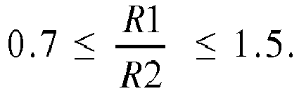
- The axial distance X1 between the
frontal surface 16d of the inner ring and the centre C1 of thetoroidal portion 26a of the groove of said ring, and the axial distance X2 between theinner face 36 of the shield and the centre C2 of theanchorage portion 24b in a free state of said shield are defined by:
- The diameter D2 of the
anchorage portion 24b in a free state of the shield and the diameter D1 of the outeraxial portion 26 of the groove of the inner ring are defined by:
- In the disclosed example, each shield is fixed on the inner ring. Alternatively, it could be possible to fix each shield on the outer ring. In this case, each anchorage groove is formed on the outer surface of the outer ring. In the disclosed example, the bearing is provided with two seals cooperating with the shields. Alternatively, the bearing may be deprived of such seals.
- The invention has been illustrated on the basis of a rolling bearing provided with at least one row of rolling elements radially disposed between the inner and outer rings. Alternatively, the bearing may be a plain bearing or a sliding bearing comprising two rings.
Claims (14)
- Bearing comprising an inner ring (16), an outer ring (14) and at least one shield (24) provided with an anchorage portion (24b) fixed into a groove (26) formed on one of the rings, characterized in that said groove comprises a toroidal portion (26a) axially offset inwards with respect to a frontal surface (16d) of the said ring and in contact with the anchorage portion (24b) of the shield, and an inner axial portion (26b) extending inwards said toroidal portion.
- Bearing according to claim 1, wherein the anchorage portion (24b) of the shield comprises a toroidal surface (38) in contact with the toroidal portion (26a) of said groove.
- Bearing according to claim 2, wherein the radius (R1) of the toroidal portion (26a) of said groove and the radius (R2) of the anchorage portion (24b) of the shield in a free state of said shield are defined by:

- Bearing according to claim 3, wherein said radii are equal.
- Bearing according to claim 3 or 4, wherein the axial distance (X1) between the frontal surface (16d) of the said ring and the centre (C1) of the toroidal portion (26a) of said groove, and the axial distance (X2) between an inner face (36) of the shield and the centre (C2) of the anchorage portion (24b) in a free state of said shield are defined by:

- Bearing according to any of the preceding claims, wherein the diameter (D2) of the anchorage portion (24b) in a free state of said shield and the diameter (D1) of the outer axial portion (25d) of said groove are defined by:

- Bearing according to claim 6, wherein said diameters are equal.
- Bearing according to any of the preceding claims, wherein said groove further comprises an outer axial portion (26d) extending outwards the toroidal portion (26a).
- Bearing according to claim 8, wherein the outer axial portion (26d) extends directly from the toroidal portion (26a).
- Bearing according to any of the preceding claims, wherein the shield (24) comprises a radial abutment portion (24a), the anchorage portion (24b) extending from said abutment portion axially towards said ring (16).
- Bearing according to any of the preceding claims, wherein the radial abutment portion (24a) of the shield (24) is in axial direct contact with the frontal surface (16d) of the said ring.
- Bearing according to any of the preceding claims, wherein the shield (24) is made in one part.
- Bearing according to any of the preceding claims, further comprising at least an additional seal (22) mounted on the other ring and which applies a dynamic sealing with said ring.
- Bearing according to claim 13, wherein said additional seal (22) comprises at least a lip (34) in friction contact with the shield.
Priority Applications (1)
| Application Number | Priority Date | Filing Date | Title |
|---|---|---|---|
| EP15306663.4A EP3156673A1 (en) | 2015-10-16 | 2015-10-16 | Bearing with sealing shield |
Applications Claiming Priority (1)
| Application Number | Priority Date | Filing Date | Title |
|---|---|---|---|
| EP15306663.4A EP3156673A1 (en) | 2015-10-16 | 2015-10-16 | Bearing with sealing shield |
Publications (1)
| Publication Number | Publication Date |
|---|---|
| EP3156673A1 true EP3156673A1 (en) | 2017-04-19 |
Family
ID=54337714
Family Applications (1)
| Application Number | Title | Priority Date | Filing Date |
|---|---|---|---|
| EP15306663.4A Withdrawn EP3156673A1 (en) | 2015-10-16 | 2015-10-16 | Bearing with sealing shield |
Country Status (1)
| Country | Link |
|---|---|
| EP (1) | EP3156673A1 (en) |
Citations (7)
| Publication number | Priority date | Publication date | Assignee | Title |
|---|---|---|---|---|
| US3519316A (en) * | 1967-06-16 | 1970-07-07 | Skf Svenska Kullagerfab Ab | Rolling bearing unit |
| SE331006B (en) * | 1967-06-16 | 1970-12-07 | Skf Svenska Kullagerfab Ab | |
| DE1750844A1 (en) * | 1967-06-16 | 1971-09-30 | Skf Svenska Kullagerfab Ab | Bearing arrangement in roller bearings |
| FR2515288A1 (en) * | 1981-10-22 | 1983-04-29 | Skf Cie Applic Mecanique | Roller bearing with sealed housing - has fixed deflectors with triple leaf seals and rotating deflectors |
| WO2011121385A1 (en) | 2010-04-02 | 2011-10-06 | Aktiebolaget Skf | Rolling bearing comprising a sealing gasket and an annular shield |
| DE102010051230A1 (en) * | 2010-11-12 | 2012-05-16 | Schaeffler Technologies Gmbh & Co. Kg | Sealed rolling bearing |
| FR3018568A1 (en) * | 2014-03-11 | 2015-09-18 | Skf Ab | BEARING BEARING COMPRISING AN ENVELOPE FOR MAINTAINING ONE OF THE RINGS AND A DEVICE FOR SEALING |
-
2015
- 2015-10-16 EP EP15306663.4A patent/EP3156673A1/en not_active Withdrawn
Patent Citations (7)
| Publication number | Priority date | Publication date | Assignee | Title |
|---|---|---|---|---|
| US3519316A (en) * | 1967-06-16 | 1970-07-07 | Skf Svenska Kullagerfab Ab | Rolling bearing unit |
| SE331006B (en) * | 1967-06-16 | 1970-12-07 | Skf Svenska Kullagerfab Ab | |
| DE1750844A1 (en) * | 1967-06-16 | 1971-09-30 | Skf Svenska Kullagerfab Ab | Bearing arrangement in roller bearings |
| FR2515288A1 (en) * | 1981-10-22 | 1983-04-29 | Skf Cie Applic Mecanique | Roller bearing with sealed housing - has fixed deflectors with triple leaf seals and rotating deflectors |
| WO2011121385A1 (en) | 2010-04-02 | 2011-10-06 | Aktiebolaget Skf | Rolling bearing comprising a sealing gasket and an annular shield |
| DE102010051230A1 (en) * | 2010-11-12 | 2012-05-16 | Schaeffler Technologies Gmbh & Co. Kg | Sealed rolling bearing |
| FR3018568A1 (en) * | 2014-03-11 | 2015-09-18 | Skf Ab | BEARING BEARING COMPRISING AN ENVELOPE FOR MAINTAINING ONE OF THE RINGS AND A DEVICE FOR SEALING |
Similar Documents
| Publication | Publication Date | Title |
|---|---|---|
| KR20160055064A (en) | Sealing device | |
| CN103201528B (en) | sealed rolling bearings | |
| KR102490203B1 (en) | Rolling bearing comprising a sealing flange | |
| KR20160111959A (en) | Rolling bearing with seal | |
| US10330156B2 (en) | Axle roller bearing seal shroud | |
| US20150377299A1 (en) | Rolling bearing with sealing subassembly | |
| EP2085666B1 (en) | Sealing device and rolling bearing device | |
| US11982311B2 (en) | Rolling bearing | |
| US20160017926A1 (en) | Bearing device with sealing device | |
| US20150345562A1 (en) | Rolling bearing with sealing subassembly | |
| CN106499734B (en) | Sealing device for roller bearing unit | |
| US20180149203A1 (en) | Sealing device, notably for a rolling bearing | |
| EP2500592A1 (en) | Sealing device, notably for a rolling bearing | |
| KR101734691B1 (en) | A Flinger For Bearing Having Preventing Means for Bending | |
| US10584742B2 (en) | Rolling bearing | |
| US9644680B2 (en) | Rolling bearing comprising a sealing flange | |
| EP3034899B1 (en) | Seal for self aligning roller bearing | |
| US9810265B2 (en) | Bearing having a sealing flange | |
| WO2025057737A1 (en) | Seal member and rolling bearing with seal | |
| JP2014101968A (en) | Rolling bearing and slide door | |
| JP2014005904A (en) | Bearing device for axle | |
| JP2017215020A (en) | Rolling bearing |
Legal Events
| Date | Code | Title | Description |
|---|---|---|---|
| PUAI | Public reference made under article 153(3) epc to a published international application that has entered the european phase |
Free format text: ORIGINAL CODE: 0009012 |
|
| AK | Designated contracting states |
Kind code of ref document: A1 Designated state(s): AL AT BE BG CH CY CZ DE DK EE ES FI FR GB GR HR HU IE IS IT LI LT LU LV MC MK MT NL NO PL PT RO RS SE SI SK SM TR |
|
| AX | Request for extension of the european patent |
Extension state: BA ME |
|
| STAA | Information on the status of an ep patent application or granted ep patent |
Free format text: STATUS: THE APPLICATION IS DEEMED TO BE WITHDRAWN |
|
| 18D | Application deemed to be withdrawn |
Effective date: 20171020 |