EP3156670A1 - Sealing system for fasteners - Google Patents
Sealing system for fasteners Download PDFInfo
- Publication number
- EP3156670A1 EP3156670A1 EP16193123.3A EP16193123A EP3156670A1 EP 3156670 A1 EP3156670 A1 EP 3156670A1 EP 16193123 A EP16193123 A EP 16193123A EP 3156670 A1 EP3156670 A1 EP 3156670A1
- Authority
- EP
- European Patent Office
- Prior art keywords
- housing
- fastener
- sealing assembly
- fuel tank
- base
- Prior art date
- Legal status (The legal status is an assumption and is not a legal conclusion. Google has not performed a legal analysis and makes no representation as to the accuracy of the status listed.)
- Granted
Links
Images



Classifications
-
- F—MECHANICAL ENGINEERING; LIGHTING; HEATING; WEAPONS; BLASTING
- F16—ENGINEERING ELEMENTS AND UNITS; GENERAL MEASURES FOR PRODUCING AND MAINTAINING EFFECTIVE FUNCTIONING OF MACHINES OR INSTALLATIONS; THERMAL INSULATION IN GENERAL
- F16J—PISTONS; CYLINDERS; SEALINGS
- F16J15/00—Sealings
- F16J15/02—Sealings between relatively-stationary surfaces
-
- F—MECHANICAL ENGINEERING; LIGHTING; HEATING; WEAPONS; BLASTING
- F16—ENGINEERING ELEMENTS AND UNITS; GENERAL MEASURES FOR PRODUCING AND MAINTAINING EFFECTIVE FUNCTIONING OF MACHINES OR INSTALLATIONS; THERMAL INSULATION IN GENERAL
- F16B—DEVICES FOR FASTENING OR SECURING CONSTRUCTIONAL ELEMENTS OR MACHINE PARTS TOGETHER, e.g. NAILS, BOLTS, CIRCLIPS, CLAMPS, CLIPS OR WEDGES; JOINTS OR JOINTING
- F16B37/00—Nuts or like thread-engaging members
- F16B37/14—Cap nuts; Nut caps or bolt caps
-
- B—PERFORMING OPERATIONS; TRANSPORTING
- B64—AIRCRAFT; AVIATION; COSMONAUTICS
- B64D—EQUIPMENT FOR FITTING IN OR TO AIRCRAFT; FLIGHT SUITS; PARACHUTES; ARRANGEMENT OR MOUNTING OF POWER PLANTS OR PROPULSION TRANSMISSIONS IN AIRCRAFT
- B64D37/00—Arrangements in connection with fuel supply for power plant
- B64D37/02—Tanks
- B64D37/06—Constructional adaptations thereof
-
- B—PERFORMING OPERATIONS; TRANSPORTING
- B64—AIRCRAFT; AVIATION; COSMONAUTICS
- B64D—EQUIPMENT FOR FITTING IN OR TO AIRCRAFT; FLIGHT SUITS; PARACHUTES; ARRANGEMENT OR MOUNTING OF POWER PLANTS OR PROPULSION TRANSMISSIONS IN AIRCRAFT
- B64D45/00—Aircraft indicators or protectors not otherwise provided for
- B64D45/02—Lightning protectors; Static dischargers
-
- F—MECHANICAL ENGINEERING; LIGHTING; HEATING; WEAPONS; BLASTING
- F16—ENGINEERING ELEMENTS AND UNITS; GENERAL MEASURES FOR PRODUCING AND MAINTAINING EFFECTIVE FUNCTIONING OF MACHINES OR INSTALLATIONS; THERMAL INSULATION IN GENERAL
- F16B—DEVICES FOR FASTENING OR SECURING CONSTRUCTIONAL ELEMENTS OR MACHINE PARTS TOGETHER, e.g. NAILS, BOLTS, CIRCLIPS, CLAMPS, CLIPS OR WEDGES; JOINTS OR JOINTING
- F16B33/00—Features common to bolt and nut
- F16B33/004—Sealing; Insulation
-
- F—MECHANICAL ENGINEERING; LIGHTING; HEATING; WEAPONS; BLASTING
- F16—ENGINEERING ELEMENTS AND UNITS; GENERAL MEASURES FOR PRODUCING AND MAINTAINING EFFECTIVE FUNCTIONING OF MACHINES OR INSTALLATIONS; THERMAL INSULATION IN GENERAL
- F16B—DEVICES FOR FASTENING OR SECURING CONSTRUCTIONAL ELEMENTS OR MACHINE PARTS TOGETHER, e.g. NAILS, BOLTS, CIRCLIPS, CLAMPS, CLIPS OR WEDGES; JOINTS OR JOINTING
- F16B47/00—Suction cups for attaching purposes; Equivalent means using adhesives
-
- F—MECHANICAL ENGINEERING; LIGHTING; HEATING; WEAPONS; BLASTING
- F16—ENGINEERING ELEMENTS AND UNITS; GENERAL MEASURES FOR PRODUCING AND MAINTAINING EFFECTIVE FUNCTIONING OF MACHINES OR INSTALLATIONS; THERMAL INSULATION IN GENERAL
- F16B—DEVICES FOR FASTENING OR SECURING CONSTRUCTIONAL ELEMENTS OR MACHINE PARTS TOGETHER, e.g. NAILS, BOLTS, CIRCLIPS, CLAMPS, CLIPS OR WEDGES; JOINTS OR JOINTING
- F16B5/00—Joining sheets or plates, e.g. panels, to one another or to strips or bars parallel to them
- F16B5/02—Joining sheets or plates, e.g. panels, to one another or to strips or bars parallel to them by means of fastening members using screw-thread
-
- F—MECHANICAL ENGINEERING; LIGHTING; HEATING; WEAPONS; BLASTING
- F16—ENGINEERING ELEMENTS AND UNITS; GENERAL MEASURES FOR PRODUCING AND MAINTAINING EFFECTIVE FUNCTIONING OF MACHINES OR INSTALLATIONS; THERMAL INSULATION IN GENERAL
- F16J—PISTONS; CYLINDERS; SEALINGS
- F16J15/00—Sealings
- F16J15/02—Sealings between relatively-stationary surfaces
- F16J15/06—Sealings between relatively-stationary surfaces with solid packing compressed between sealing surfaces
-
- F—MECHANICAL ENGINEERING; LIGHTING; HEATING; WEAPONS; BLASTING
- F16—ENGINEERING ELEMENTS AND UNITS; GENERAL MEASURES FOR PRODUCING AND MAINTAINING EFFECTIVE FUNCTIONING OF MACHINES OR INSTALLATIONS; THERMAL INSULATION IN GENERAL
- F16B—DEVICES FOR FASTENING OR SECURING CONSTRUCTIONAL ELEMENTS OR MACHINE PARTS TOGETHER, e.g. NAILS, BOLTS, CIRCLIPS, CLAMPS, CLIPS OR WEDGES; JOINTS OR JOINTING
- F16B47/00—Suction cups for attaching purposes; Equivalent means using adhesives
- F16B47/003—Suction cups for attaching purposes; Equivalent means using adhesives using adhesives for attaching purposes
Definitions
- an apparatus comprising a housing.
- the housing has a base and a cap.
- the cap is configured to cover a portion of a fastener extending through a surface.
- the housing is configured to apply suction to the surface.
- components such as fasteners, hoses, tubing, or other components that extend into the wing
- components can be sealed to exclude the outside from the inside, or covered to reduce or eliminate the buildup of electrical charge on conductive surfaces.
- These components can extend through structures within the fuel tank, such as stringers, or between bays of the fuel tank via holes in the structures forming the fuel tank, such as ribs or other supporting structures.
- components and the holes through which they extend may be sealed to reduce leaking or seepage of the fuel tank formed in the wing.
- aircraft 100 has wing 102 and wing 104 attached to body 106.
- Aircraft 100 includes engine 108 attached to wing 102 and engine 110 attached to wing 104.
- Pressure sensitive adhesive 258 may be a permanent or temporary adhesive. For example, pressure sensitive adhesive 258 may continue to hold housing 230 in place over fastener 215 throughout use of platform 201. In other illustrative examples, pressure sensitive adhesive 258 may temporarily hold housing 230 in place over fastener 215.
- adhesive 260 may be present between base 233 and surface 229. In this example, pressure sensitive adhesive 258 may hold housing 230 in place as adhesive 260 cures. After adhesive 260 is cured, at least one of adhesive 260 and suction 232 may hold housing 230 in place over fastener 215.
- adhesive 260 may be the primary component holding housing 230 in place over fastener 215. Adhesive 260 may be optional.
- Process 900 may press a housing over an end of the fastener such that a portion of the housing conforms to a portion of the fastener, the housing including a base and a cap (operation 902 ).
- pressing the housing over the end of the fastener comprises applying the housing over the end of the fastener such that a space between the housing and the surface has a lower air pressure than an air pressure outside of the housing.
Landscapes
- Engineering & Computer Science (AREA)
- General Engineering & Computer Science (AREA)
- Mechanical Engineering (AREA)
- Aviation & Aerospace Engineering (AREA)
- Gasket Seals (AREA)
- Slide Fasteners, Snap Fasteners, And Hook Fasteners (AREA)
- Connection Of Plates (AREA)
Abstract
Description
- The present disclosure relates generally to protection for fasteners. In particular, the present disclosure relates to a method and apparatus for sealing fasteners.
- In composite structures, the sealing of metal surfaces and the holes that penetrate the structure may have a number of purposes, including the reduction of fuel leakage, with respect to fuel leaking out of the tank, the reduction of other fluids entering or exiting the fuel tank, the coverage of metal components that can have a propensity to accumulate electrical charge, or the prevention of galvanic corrosion.
- Components, such as metallic fasteners, may be sealed. Sealant in the form of seal caps may cover these fasteners. A "seal cap" is a structure that covers an end of a metallic component. The metallic component may be a fastener. The end may be the head fastener or the threaded end of the fastener with a nut. The fastener may be, for example, a bolt, a screw, or some other type of fastener.
- For example, a seal cap may be attached to the end of a fastener that extends into the interior of the fuel tank. This seal cap is configured to provide a seal against the flow of fuel out of the fuel tank. The seal cap may also reduce or eliminate the accumulation of electrical charge on the surface of the exposed fastener.
- Seal caps are often comprised of materials that retain sealing properties when submerged in fuel and/or when left dry for different periods of time. For example, molded polymeric seal caps may be used in fuel tanks for aircraft. These types of seal caps may fit over the protruding end of a fastener on the interior of the fuel tank. Sealants may be placed into the seal caps prior to the seal caps being placed on the fastener. The sealant may be in the form of a plastic forming material.
- For example, a seal cap may have an interior that is partially filled with an uncured sealant. This seal cap with the sealant is then pressed into place on the fastener. When in this position, excess sealant extrudes from around the bottom of the cap. This sealant may be blended around and onto the exterior of the cap. The sealant is then allowed to cure to form the final sealant material.
- However, installing molded seal caps may take an undesirable amount of time. For example, molded seal caps may be placed over fasteners manually. Manual installation may take an undesirable amount of time. Further, molded seal caps may be manually inspected for voids prior to installation over fasteners. Yet further, blending extruded sealant may be performed manually and require training to meet desired tolerances.
- Therefore, it would be desirable to have a method and apparatus that take into account at least some of the issues discussed above, as well as possibly other issues.
- In one illustrative embodiment, an apparatus is provided. The apparatus comprises a housing. The housing has a base and a cap. The cap is configured to cover a portion of a fastener extending through a surface. The housing is configured to apply suction to the surface.
- A further illustrative embodiment of the present disclosure provides an apparatus. The apparatus comprises a surface, a fastener, and a housing. The fastener has an end extending from the surface. The housing covers the end of the fastener. The housing is formed of a flexible material selected to apply suction to the surface after pressing the housing against the fastener. The housing includes a base and a cap.
- A yet further illustrative embodiment of the present disclosure provides a method of sealing a fastener that extends through a surface. A housing is pressed over an end of the fastener such that a portion of the housing conforms to a portion of the fastener. The housing includes a base and a cap. The housing is held over the fastener with suction applied by the housing to the surface.
- The features and functions can be achieved independently in various embodiments of the present disclosure or may be combined in yet other embodiments in which further details can be seen with reference to the following description and drawings.
- Further, the disclosure comprises embodiments according to the following clauses:
- Clause A1. An apparatus comprising: a surface; a fastener having an end extending from the surface; and a housing covering the end of the fastener, wherein the housing is formed of a flexible material selected to apply suction to the surface after pressing the housing against the fastener, the housing including a base and a cap.
- Clause A2. The apparatus of clause A1, wherein a space between the housing and the surface has a lower air pressure than an air pressure outside of the housing.
- Clause A3. The apparatus of clause A1-A2, wherein a first cross-section of the cap is larger than a second cross-section of the cap.
- Clause A4. The apparatus of clause A1-A3, wherein the first cross-section is closer to the base of the housing than the second cross-section.
- Clause A5. The apparatus of clause A1-A4 further comprising: an adhesive between the base of the housing and the surface.
- The novel features believed characteristic of the illustrative embodiments are set forth in the appended claims. The illustrative embodiments, however, as well as a preferred mode of use, further objectives, and features thereof will best be understood by reference to the following detailed description of an illustrative embodiment of the present disclosure when read in conjunction with the accompanying drawings, wherein:
-
Figure 1 is an illustration of an aircraft in accordance with an illustrative embodiment; -
Figure 2 is an illustration of a block diagram of a manufacturing environment in accordance with an illustrative embodiment; -
Figure 3 is an illustration of a cross-sectional view of a sealing assembly in accordance with an illustrative embodiment; -
Figure 4 is an illustration of a cross-sectional view of a sealing assembly in accordance with an illustrative embodiment; -
Figure 5 is an illustration of a cross-sectional view of a sealing assembly in accordance with an illustrative embodiment; -
Figure 6 is an illustration of a cross-sectional view of a sealing assembly in accordance with an illustrative embodiment; -
Figure 7 is an illustration of an isometric view of an installed sealing assembly in accordance with an illustrative embodiment; -
Figure 8 is an illustration of a cross-sectional view of an installed sealing assembly in accordance with an illustrative embodiment; -
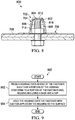
Figure 9 is an illustration of a flowchart of a method for sealing a fastener that extends through a surface in accordance with an illustrative embodiment; -
Figure 10 is an illustration of an aircraft manufacturing and service method in the form of a block diagram in accordance with an illustrative embodiment; and -
Figure 11 is an illustration of an aircraft in the form of a block diagram in which an illustrative embodiment may be implemented. - The different illustrative embodiments recognize and take into account one or more considerations. For example, the illustrative embodiments recognize and take into account that fuel tanks in aircraft are often integral structures to the aircraft. For example, the wing structure of an aircraft may be sealed. The internal cavities of the sealed wing structure may be used as a fuel tank. These types of wings are also referred to as "wet wings."
- The illustrative embodiments recognize and take into account that with a wet wing, components, such as fasteners, hoses, tubing, or other components that extend into the wing, can be sealed to exclude the outside from the inside, or covered to reduce or eliminate the buildup of electrical charge on conductive surfaces. These components can extend through structures within the fuel tank, such as stringers, or between bays of the fuel tank via holes in the structures forming the fuel tank, such as ribs or other supporting structures. In conventional fuel tanks made from metal, components and the holes through which they extend may be sealed to reduce leaking or seepage of the fuel tank formed in the wing.
- The illustrative embodiments also recognize and take into account that currently used sealing systems may employ seal caps that are configured to reduce the transfer of energy into a fuel tank system caused by an electromagnetic event. The transfer of energy may involve a spark, a static discharge, a gas under pressure, a heated gas, a mechanical force, or some other transfer of energy that may be undesirable within a fuel tank system.
- The illustrative embodiments also recognize and take into account that seal caps may add an undesired amount of time to manufacturing the structure. Yet further, the illustrative embodiments recognize and take into account that a fuel tank system may have restricted space. Movement within the fuel tank system may be limited by the size of the fuel tank system. Further, the distances between a number of fasteners in the fuel tank system may be small. The illustrative embodiments recognize and take into account that an apparatus for applying sealant in a fuel tank system should be sufficiently compact to move within the fuel tank system. Thus, the illustrative embodiments provide a method and apparatus for reducing manufacturing time for sealing fasteners in a fuel tank system, reducing a transfer of energy in a fuel tank system, or a combination of the two.
- An illustrative embodiment of the present disclosure may provide a fuel tank system. The fuel tank system may comprise a fuel tank, a number of fasteners, and a number of housings. The number of fasteners may have a number of ends extending into an interior of the fuel tank. The number of housings is configured to cover the number of ends of the number of fasteners. A housing in the number of housings is configured to cover an end of a fastener in the number of ends. The housing has a base and a cap. The housing is formed of a flexible material selected to apply suction to the fuel tank after the housing has been pressed against the fastener.
- With reference now to the figures and, in particular, with reference to
Figure 1 , an illustration of an aircraft is depicted in accordance with an illustrative embodiment. In this illustrative example,aircraft 100 haswing 102 andwing 104 attached tobody 106.Aircraft 100 includesengine 108 attached towing 102 andengine 110 attached towing 104. -
Body 106 hastail section 112.Horizontal stabilizer 114,horizontal stabilizer 116, andvertical stabilizer 118 are attached totail section 112 ofbody 106. As depicted,aircraft 100 also includesfuel tank system 120. As depicted,fuel tank system 120 includesfuel tank 122 andfuel tank 124. -
Fuel tank 122 is located inwing 102, andfuel tank 124 is located inwing 104 infuel tank system 120. In these illustrative examples,fuel tank 122 andfuel tank 124 are formed by sealing structures inside ofwing 102 andwing 104, respectively. A sealing system for fasteners infuel tank system 120 may be implemented in accordance with an illustrative embodiment. - With reference next to
Figure 2 , an illustration of a block diagram of a manufacturing environment is depicted in accordance with an illustrative embodiment. In this illustrative example,manufacturing environment 200 may be used to seal fasteners inplatform 201.Aircraft 100 ofFigure 1 is an example of a physical implementation ofplatform 201 inFigure 2 . -
Platform 201 may includefuel tank system 202.Fuel tank system 120 inFigure 1 is an example of an implementation forfuel tank system 202 inFigure 2 .Fuel tank system 202 includes number offuel tanks 203. As used herein, a "number of," when used with reference to items, means one or more items. For example, "number offuel tanks 203" is one or more fuel tanks.Fuel tank 122 andfuel tank 124 inFigure 1 are examples of fuel tanks that may be in number offuel tanks 203. A fuel tank in number offuel tanks 203 also may be in locations other than inwing 102 andwing 104 ofaircraft 100. For example, a fuel tank may be located inbody 106 ofaircraft 100. - In some illustrative examples, number of
fasteners 204 may be installed infuel tank 205 in number offuel tanks 203. In particular, number offasteners 204 may be installed in number ofholes 206 formed instructures 207.Structures 207 may be structures forming or supportingfuel tank 205.Structures 207 may include at least one of a number of ribs, a number of spars, a number of skins, or other structures. Number offasteners 204 may have a large quantity of fasteners. For example, number offasteners 204 may include between 20,000 and 80,000 fasteners. When number offasteners 204 includes a large quantity of fasteners, even small increases in time for an individual fastener related to manufacturing, sealing, or inspecting may increase overall manufacturing time by a large amount of time. - Number of
fasteners 204 has number of first ends 208 and number of second ends 209. Number of first ends 208 may extend intointerior 210 offuel tank 205. In these illustrative examples, number of second ends 209 is onexterior 211 offuel tank 205. - In this illustrative example, sealing
assembly 212 may be used infuel tank 205 in number offuel tanks 203.Sealing assembly 212 may be one of plurality of sealingassemblies 213. - Plurality of sealing
assemblies 213 may be used to seal number offasteners 204 installed infuel tank 205. More particularly, plurality of sealingassemblies 213 may be used to seal number ofholes 206 instructures 207 offuel tank 205 with number offasteners 204 installed in number ofholes 206. - In particular, sealing
assembly 212 may be used to seal a fastener in number offasteners 204 installed infuel tank 205. More specifically, sealingassembly 212 may be used to seal a hole in number ofholes 206 instructures 207 offuel tank 205 with number offasteners 204 installed in number ofholes 206. -
Sealing assembly 212 may be designed for coveringfirst end 214 offastener 215. In some illustrative examples, sealingassembly 212 may be the same as other sealing assemblies of plurality of sealingassemblies 213. In other illustrative examples, sealingassembly 212 may be different from other sealing assemblies of plurality of sealingassemblies 213. - For example, plurality of sealing
assemblies 213 may be designed to seal number of first ends 208 of number offasteners 204. In some illustrative examples, number offasteners 204 may be of a variety of sizes. For example, number offasteners 204 may have a variety of diameters. Plurality of sealingassemblies 213 may have a variety of at least one of shapes or sizes to desirably seal number offasteners 204 having a variety of diameters. - As another example, number of first ends 208 may have a variety of lengths. Plurality of sealing
assemblies 213 may have a variety of at least one of shapes or sizes to desirably cover and seal number of first ends 208 of number offasteners 204. - As depicted, sealing
assembly 212 may be configured to coverfirst end 214 offastener 215 in number offasteners 204.Sealing assembly 212 may form a barrier betweenfirst end 214 offastener 215 andinterior 210 offuel tank 205. -
First end 214 offastener 215 is an end within number of first ends 208 that extends intointerior 210 offuel tank 205 fromstructures 207. In these illustrative examples,fastener 215 is installed inhole 216 within number ofholes 206 infuel tank 205. - In the illustrative examples, sealing
assembly 212 is configured to reduce effects resulting fromelectromagnetic event 217. In particular, sealingassembly 212 may be configured to reduce the transfer ofenergy 218 into or withininterior 210 offuel tank 205. The transfer ofenergy 218 may be intointerior 210 offuel tank 205 from current caused byelectromagnetic event 217. The transfer ofenergy 218 may be withininterior 210 offuel tank 205 from electrostatic charge that builds up on metal components withininterior 210 offuel tank 205. - In the illustrative examples,
electromagnetic event 217 may be, for example, without limitation, a lightning strike, electrostatic discharge, or other types of discharge forplatform 201.Electromagnetic event 217 may transferenergy 218 toplatform 201. - In these illustrative examples,
energy 218 may take a number of different forms. For example,energy 218 may be at least one of a spark, an electrostatic discharge, heat, a mechanical force, a moving particle, or some other form of energy that may be undesirable withininterior 210 offuel tank 205. As used herein, the phrase "at least one of," when used with a list of items, means different combinations of one or more of the listed items may be used, and only one of each item in the list may be needed. For example, "at least one of item A, item B, and item C" may include, without limitation, item A, or item A and item B. This example also may include item A, item B, and item C, or item B and item C. - In an illustrative example, energetic particles may originate from one or more of number of first ends 208 of number of
fasteners 204 in response toelectromagnetic event 217. In the illustrative examples, sealingassembly 212 is configured to reduce and/or preventenergy 218 from being transferred into or withininterior 210 offuel tank 205.Sealing assembly 212 is configured to containenergy 218, absorbenergy 218, or a combination of the two. By containingenergy 218, absorbingenergy 218, or a combination of the two, the amount ofenergy 218 reachinginterior 210 offuel tank 205 may be reduced, prevented, or both. In these illustrative examples, containingenergy 218 means that the amount ofenergy 218 reachinginterior 210 offuel tank 205 is reduced, prevented, or both. -
Material 220 of sealingassembly 212 may be selected to provide desirable characteristics. In the illustrative examples,material 220 of sealingassembly 212 may be selected as one that does not retain undesired amounts of electric charges.Material 220 of sealingassembly 212 may be selected as one that is electrostatically conductive. In some illustrative examples,material 220 may bepolymeric material 222. In some illustrative examples, whenmaterial 220 ispolymeric material 222, sealingassembly 212 may be thermoset 224 or thermoplasticelastomeric material 226. - A thermoset material may become hard when heated. A thermoplastic material may become soft upon heating and may harden upon cooling. A thermoplastic material may be able to be repeatedly heated and cooled.
- As another example,
material 220 of sealingassembly 212 may be selected as having properties configured to containenergy 218 in the form of thermal energy. The thermal energy may be, for example, in the form of a spark or heated gas. -
Material 220 of sealingassembly 212 may be selected for desirable inspection or application properties. For example,material 220 of sealingassembly 212 may be selected such that sealingassembly 212 is substantially transparent 228 after curing. When sealingassembly 212 is substantially transparent 228 after curing, sealingassembly 212 may be visually inspected for voids. - Number of
fasteners 204 may extend throughsurface 229 ofplatform 201. When number offasteners 204 is present infuel tank system 202,fastener 215 may extend throughsurface 229 infuel tank system 202. - Although number of
fasteners 204 has been discussed as being present infuel tank system 202, number offasteners 204 may be used in other locations other thanfuel tank system 202. In these other illustrative examples,surface 229 may be any desirable surface other than insidefuel tank system 202. For example,surface 229 may be an exterior surface ofplatform 201. In another illustrative example,surface 229 may be an interior surface ofplatform 201. -
Sealing assembly 212 takes the form ofhousing 230.Housing 230 is formed prior to installation over a fastener.Housing 230 may be formed using injection molding, thermos-molding, or any other desirable form of manufacturing. -
Housing 230 may be positioned such thathousing 230 coversfirst end 214 offastener 215 extending fromsurface 229.Housing 230 is configured to applysuction 232 tosurface 229.Housing 230 hasbase 233 andcap 234.Base 233 may take the form offlange 236. When sealingassembly 212 is assembled overfastener 215, base 233 contacts surface 229 ofplatform 201. -
Cap 234 is configured to cover a portion offastener 215 extending throughsurface 229. More specifically,cap 234 may coverfirst end 214 offastener 215.Cap 234 hasfirst cross-section 240 andsecond cross-section 242.First cross-section 240 is closer to base 233 ofhousing 230 thansecond cross-section 242.First cross-section 240 is larger thansecond cross-section 242. - In some illustrative examples,
cap 234 may be referred to asdome 244. In some illustrative examples,dome 244 may have a generally rounded end. In other illustrative examples,dome 244 may have a substantially flat end. In some illustrative examples,dome 244 may be substantially conical. -
Cap 234 hasinternal cavity 246.Internal cavity 246 may be designed to coverfirst end 214 offastener 215. Shape 248 ofinternal cavity 246 may be designed based onfastener 215. Shape 248 of internal cavity may be designed based on at least one of the size, shape, or length offirst end 214 offastener 215. -
Internal cavity 246 may be designed such that a portion ofinternal cavity 246contacts fastener 215 when sealingassembly 212 is assembled overfastener 215.Internal cavity 246 may be designed such thatspace 250 betweeninternal cavity 246 andfastener 215 is desirable.Space 250 may be a total amount of volume betweeninternal cavity 246 ofcap 234 andfastener 215. For example, it may be desirable to minimizespace 250 withininternal cavity 246 when sealingassembly 212 is installed overfastener 215. -
Sealing assembly 212 may be positioned overfastener 215. After positioning sealingassembly 212 overfastener 215, pressure may be applied to cap 234 to presshousing 230 overfirst end 214 offastener 215 such that a portion ofhousing 230 conforms to a portion offastener 215. - When housing 230 is pressed over
first end 214 offastener 215,housing 230 is held overfastener 215 bysuction 232 applied byhousing 230 tosurface 229.Housing 230 may be described as acting as a suction cup. -
Material 220 ofhousing 230 may be flexible 252 such thathousing 230 acts as a suction cup. Whenmaterial 220 ofhousing 230 is flexible 252, a portion ofcap 234 may conform to a portion offastener 215. - When housing 230 is held against
surface 229 bysuction 232,air pressure 254 withinspace 250 is lower thanair pressure 256 outside ofhousing 230. Whenair pressure 254 is lower thanair pressure 256,air pressure 254 may be referred to as negative pressure.Air pressure 256 outside ofhousing 230 may be about atmospheric pressure. In some illustrative examples,space 250 may be referred as a space withinhousing 230. In other illustrative examples,space 250 may be referred to as a space betweenhousing 230 andsurface 229. - When
air pressure 254 is lower thanair pressure 256 outside ofhousing 230,housing 230 may have desirable characteristics during operation ofplatform 201. For example, whenplatform 201 is an aircraft such asaircraft 100 ofFigure 1 ,air pressure 256 may be lower when the aircraft is flying than when the aircraft is on the ground. Asair pressure 256 lowers below atmospheric pressure,housing 230 may still havesuction 232. Ifair pressure 254 andair pressure 256 were both about atmospheric pressure,housing 230 may come off offastener 215 asair pressure 256 decreases during flight. - When
platform 201 is an aircraft, air withinhousing 230 will expand when the aircraft is at a cruising altitude. Ifair pressure 254 was atmospheric pressure, the air insidehousing 230 may expand during flight and push againsthousing 230. By pushing againsthousing 230, the air insidehousing 230 may break the seal ofhousing 230. Byair pressure 254 being lower thanair pressure 256, the air withinhousing 230 may not provide an undesirable amount of pressure againsthousing 230. - In some illustrative examples,
suction 232 alone may holdhousing 230 overfastener 215. In some other illustrative examples, additional holding components may holdhousing 230 overfastener 215. For example, pressuresensitive adhesive 258 may be present ininternal cavity 246. When pressuresensitive adhesive 258 is present, both pressuresensitive adhesive 258 andsuction 232 may holdhousing 230 in place overfastener 215. - Pressure
sensitive adhesive 258 may be a permanent or temporary adhesive. For example, pressuresensitive adhesive 258 may continue to holdhousing 230 in place overfastener 215 throughout use ofplatform 201. In other illustrative examples, pressuresensitive adhesive 258 may temporarily holdhousing 230 in place overfastener 215. In one example, adhesive 260 may be present betweenbase 233 andsurface 229. In this example, pressuresensitive adhesive 258 may holdhousing 230 in place as adhesive 260 cures. After adhesive 260 is cured, at least one ofadhesive 260 andsuction 232 may holdhousing 230 in place overfastener 215. For example, adhesive 260 may be the primarycomponent holding housing 230 in place overfastener 215. Adhesive 260 may be optional. - In some illustrative examples, sealing
assembly 212 may further include number of self-lockingflanges 262. Number of self-lockingflanges 262 may also be formed ofmaterial 220. Number of self-lockingflanges 262 may extend fromhousing 230 intointerior 264 ofhousing 230. Pressinghousing 230 overfirst end 214 offastener 215 may include applyinghousing 230 such that number of self-lockingflanges 262 engagefastener 215. - In some illustrative examples, number of self-locking
flanges 262 may provide supplementary holding forhousing 230. In some illustrative examples, number of self-lockingflanges 262 may provide primary holding forhousing 230. In some illustrative examples, number of self-lockingflanges 262 may be used in conjunction with other holding components such as at least one ofsuction 232, pressuresensitive adhesive 258, or adhesive 260. - Number of self-locking
flanges 262 may centerhousing 230 relative tofastener 215. By centeringhousing 230 relative tofastener 215, number of self-lockingflanges 262 may minimizespace 250. - In other illustrative examples,
material 220 may provide holding forhousing 230. For example, whenbase 233 is formed of thermoplasticelastomeric material 226,base 233 may be heated. Byheating base 233, thermoplasticelastomeric material 226 may become pliable and sticky. Byheating base 233, thermoplasticelastomeric material 226 may bond to surface 229. -
Sealing assembly 212 may be installed overfastener 215 in any desirable fashion. In some illustrative examples, sealingassembly 212 may be pressed ontofastener 215 manually. In another illustrative example,robotic arm 266 may move sealingassembly 212 withinfuel tank system 202.Robotic arm 266 may install sealingassembly 212 onto a fastener in number offasteners 204, such asfastener 215. - The illustration of
manufacturing environment 200 inFigure 2 is not meant to imply physical or architectural limitations to the manner in which an illustrative embodiment may be implemented. Other components in addition to or in place of the ones illustrated may be used. Some components may be unnecessary. Also, the blocks are presented to illustrate some functional components. One or more of these blocks may be combined, divided, or combined and divided into different blocks when implemented in an illustrative embodiment. - For example, each of number of self-locking
flanges 262, adhesive 260, and pressuresensitive adhesive 258 may be optional. In some illustrative examples, sealingassembly 212 may include at least one of heated thermoplasticelastomeric material 226 ofbase 233, number of self-lockingflanges 262, adhesive 260, or pressuresensitive adhesive 258. Further, in some illustrative examples, sealingassembly 212 may include none of heated thermoplasticelastomeric material 226 ofbase 233, number of self-lockingflanges 262, adhesive 260, or pressuresensitive adhesive 258. - Turning now to
Figure 3 , an illustration of a cross-sectional view of a sealing assembly is depicted in accordance with an illustrative embodiment.Sealing assembly 300 may be a physical implementation of sealingassembly 212 ofFigure 2 .Sealing assembly 300 includeshousing 302 placed overfastener 304.First end 306 offastener 304 extends throughsurface 308. As depicted,housing 302 is in an uninstalled position. To sealfastener 304 usinghousing 302,housing 302 may be pressed indirection 310 ontofastener 304. When housing 302 is pressed indirection 310,housing 302 may be placed into an installed position. -
Housing 302 includescap 312 andbase 314. As depicted, number of self-lockingflanges 315 extends fromhousing 302 intointerior 316 ofhousing 302. Additionally, adhesive 318 is positioned betweenbase 314 andsurface 308. - When housing 302 is pressed in
direction 310, suction created byhousing 302 may holdhousing 302 in place relative to surface 308 andfastener 304 while adhesive 318 cures. When housing 302 is installed overfastener 304, at least one of number of self-lockingflanges 315, adhesive 318, or suction may holdhousing 302 in place relative to surface 308 andfastener 304. - Turning now to
Figure 4 , an illustration of a cross-sectional view of a sealing assembly is depicted in accordance with an illustrative embodiment.Sealing assembly 400 may be a physical implementation of sealingassembly 212 ofFigure 2 .Sealing assembly 400 includeshousing 402 placed overfastener 404.First end 406 offastener 404 extends throughsurface 408. As depicted,housing 402 is in an uninstalled position. To sealfastener 404 usinghousing 402,housing 402 may be pressed indirection 410 ontofastener 404. -
Housing 402 includescap 412 andbase 414. As depicted, adhesive 416 is positioned betweenbase 414 andsurface 408. - When housing 402 is pressed in
direction 410, suction created byhousing 402 may holdhousing 402 in place relative to surface 408 andfastener 404 while adhesive 416 cures. When housing 402 is installed overfastener 404, at least one of adhesive 416 or suction may holdhousing 402 in place relative to surface 408 andfastener 404. - Turning now to
Figure 5 , an illustration of a cross-sectional view of a sealing assembly is depicted in accordance with an illustrative embodiment.Sealing assembly 500 may be a physical implementation of sealingassembly 212 ofFigure 2 .Sealing assembly 500 includeshousing 502 placed overfastener 504.First end 506 offastener 504 extends throughsurface 508. As depicted,housing 502 is in an uninstalled position. To sealfastener 504 usinghousing 502,housing 502 may be pressed indirection 510 ontofastener 504. -
Housing 502 includescap 512 andbase 514. As depicted, number of self-lockingflanges 515 extends fromhousing 502 intointerior 516 ofhousing 502. When housing 502 is installed overfastener 504, at least one of number of self-lockingflanges 515 or suction may holdhousing 502 in place relative to surface 508 andfastener 504. - Turning now to
Figure 6 , an illustration of a cross-sectional view of a sealing assembly is depicted in accordance with an illustrative embodiment.Sealing assembly 600 may be a physical implementation of sealingassembly 212 ofFigure 2 .Sealing assembly 600 includeshousing 602 placed overfastener 604.First end 606 offastener 604 extends throughsurface 608. As depicted,housing 602 is in an uninstalled position. To sealfastener 604 usinghousing 602,housing 602 may be pressed indirection 610 ontofastener 604. -
Housing 602 includescap 612 andbase 614. When housing 602 is pressed indirection 610, suction created byhousing 602 may holdhousing 602 in place relative to surface 608 andfastener 604. - Turning now to
Figure 7 , an illustration of an isometric view of an installed sealing assembly is depicted in accordance with an illustrative embodiment. Installed sealingassembly 700 may be a physical implementation of sealingassembly 212 ofFigure 2 . Installed sealingassembly 700 may be an example of either sealingassembly 400 ofFigure 4 or sealingassembly 600 ofFigure 6 in an installed state. - Installed sealing
assembly 700 includeshousing 702, havingcap 704 andbase 706. In this installed state,base 706 is substantially flat againstsurface 708. - Installed sealing
assembly 700 may be held in place overfastener 714 by at least one of suction or adhesive positioned betweenbase 706 andsurface 708. As depicted,fastener 716 is not yet sealed. In some illustrative examples, a sealant assembly substantially the same as installed sealingassembly 700 may be used to sealfastener 716. In other illustrative examples,fastener 714 andfastener 716 may be different. For example, a length offastener 716 extending fromsurface 708 may be greater than a length offastener 714 extending fromsurface 708. In another illustrative example,fastener 714 andfastener 716 may have different diameters. Whenfastener 714 andfastener 716 are different, a sealing assembly to sealfastener 716 may be different than sealingassembly 700. For example, at least one of the base size, cap shape, interior cavity shape, or other desirable characteristic of the sealing assembly may be different from sealingassembly 700. - As depicted,
housing 702 of sealingassembly 700 is transparent 718. When housing 702 is transparent 718, inspection ofhousing 702 may be faster than ifhousing 702 were not transparent 718. For example, out of tolerance conditions may be visible throughhousing 702 whenhousing 702 is transparent 718. - Turning now to
Figure 8 , an illustration of a cross-sectional view of an installed sealing assembly is depicted in accordance with an illustrative embodiment. View 800 may be a cross-sectional view of sealingassembly 700 along 8 ofFigure 7 . - As depicted,
portion 802 ofhousing 702contacts portion 804 offastener 714.Space 806 betweenhousing 702 andsurface 708 is desirably small. Minimizingspace 806 may also minimize the amount of air withininterior cavity 808 ofcap 704.Space 806 withininterior cavity 808 ofcap 704 also desirably has an air pressure below atmospheric pressure. - The different components shown in
Figures 1 and3 -8 may be combined with components inFigure 2 , used with components inFigure 2 , or a combination of the two. Additionally, some of the components inFigures 1 and3 -8 may be illustrative examples of how components shown in block form inFigure 2 can be implemented as physical structures. - Turning now to
Figure 9 , an illustration of a flowchart of a method of sealing a fastener that extends through a surface is depicted in accordance with an illustrative embodiment.Process 900 may be a process of sealingfastener 215 ofFigure 2 .Process 900 may be a process of sealing a fastener inaircraft 100 ofFigure 1 . -
Process 900 may press a housing over an end of the fastener such that a portion of the housing conforms to a portion of the fastener, the housing including a base and a cap (operation 902). In some illustrative examples, pressing the housing over the end of the fastener comprises applying the housing over the end of the fastener such that a space between the housing and the surface has a lower air pressure than an air pressure outside of the housing. - In some illustrative examples, a number of self-locking flanges extend from the housing into an interior of the housing, and pressing the housing over the end of the fastener comprises applying the housing such that the number of self-locking flanges engages the fastener. In some illustrative examples, the number of self-locking flanges engaging the fastener holds the housing relative to the fastener while an adhesive between the housing and the surface cures.
-
Process 900 may then hold the housing over the fastener with suction applied by the housing to the surface (operation 904). Afterwards the process terminates. In some illustrative examples, the suction holds the housing relative to the fastener while an adhesive between the housing and the surface cures. - The flowcharts and block diagrams in the different depicted embodiments illustrate the architecture, functionality, and operation of some possible implementations of apparatuses and methods in an illustrative embodiment. In this regard, each block in the flowcharts or block diagrams may represent a module, a segment, a function, and/or a portion of an operation or step.
- In some alternative implementations of an illustrative embodiment, the function or functions noted in the blocks may occur out of the order noted in the Figures. For example, in some cases, two blocks shown in succession may be executed substantially concurrently, or the blocks may sometimes be performed in the reverse order, depending upon the functionality involved. Also, other blocks may be added in addition to the illustrated blocks in a flowchart or block diagram. Further, some blocks may not be implemented. For example,
Process 900 may further comprise applying an adhesive to the base of the housing. - The illustrative embodiments of the disclosure may be described in the context of aircraft manufacturing and
service method 1000 as shown inFigure 10 andaircraft 1100 as shown inFigure 11 . Turning first toFigure 10 , an illustration of a block diagram of an aircraft manufacturing and service method is depicted in accordance with an illustrative embodiment. During pre-production, aircraft manufacturing andservice method 1000 may include specification anddesign 1002 ofaircraft 1100 inFigure 11 andmaterial procurement 1004. - During production, component and
subassembly manufacturing 1006 andsystem integration 1008 ofaircraft 1100 inFigure 11 takes place. Thereafter,aircraft 1100 inFigure 11 may go through certification anddelivery 1010 in order to be placed inservice 1012. While inservice 1012 by a customer,aircraft 1100 inFigure 11 is scheduled for routine maintenance andservice 1014, which may include modification, reconfiguration, refurbishment, and other maintenance or service. - Each of the processes of aircraft manufacturing and
service method 1000 may be performed or carried out by a system integrator, a third party, and/or an operator. In these examples, the operator may be a customer. For the purposes of this description, a system integrator may include, without limitation, any number of aircraft manufacturers and major-system subcontractors; a third party may include, without limitation, any number of vendors, subcontractors, and suppliers; and an operator may be an airline, a leasing company, a military entity, a service organization, and so on. - With reference now to
Figure 11 , an illustration of a block diagram of an aircraft is depicted in which an illustrative embodiment may be implemented. In this example,aircraft 1100 is produced by aircraft manufacturing andservice method 1000 inFigure 10 and may includeairframe 1102 with a plurality ofsystems 1104 and interior 1106. Examples ofsystems 1104 include one or more ofpropulsion system 1108,electrical system 1110,hydraulic system 1112, andenvironmental system 1114. Any number of other systems may be included. Although an aerospace example is shown, different illustrative embodiments may be applied to other industries, such as the automotive industry. - The method and apparatus embodied herein may be employed during at least one of the stages of aircraft manufacturing and
service method 1000 inFigure 10 . One or more illustrative embodiments may be used during component andsubassembly manufacturing 1006. For example, sealingassembly 212 ofFigure 2 may be used to seal a fastener during component andsubassembly manufacturing 1006. Further, sealingassembly 212 may also be used to seal a fastener during maintenance andservice 1014. - The method and apparatus presented may reduce the amount of time needed to seal a fastener. Yet further, the presented sealing assembly may reduce the training or experience to seal a fastener. A sealing assembly may seal a fastener by being pressed over the fastener. Pressing a sealing assembly over a fastener may be performed manually or by a robotic system in less than a minute. In some illustrative examples, a sealing assembly may be pressed over a fastener in ten seconds or less.
- By using a pre-formed housing, excess sealant may not occur. As a result, the presented sealing assembly may not have sealant shaping, blending, or sealant removal steps. By eliminating sealant shaping, blending, or sealant removal steps, sealing a fastener may have a lower sealing time.
- The method and apparatus presented may also reduce the amount of time to manufacture a fuel tank system. A sealing assembly may be applied over an end of a fastener. By using a sealing assembly such as a pre-molded housing, a fastener may be sealed in less time than manually applying conventional seal caps. Manually applying conventional seal caps may take up to twenty minutes each. The time required to apply a conventional seal cap may be related to at least one of the location within the fuel tank system, the size of the end to be covered, the desired surface treatments, or other factors.
- By using a sealing assembly, the application processes may be reduced to less than a minute for each fastener. Thus, sealing time for the fasteners may also be reduced. By reducing sealing time, manufacturing time of the fuel tank system may be reduced. By reducing sealing time, manufacturing time of the fuel tank system may be reduced by hundreds of hours. In some illustrative examples, manufacturing time of the fuel tank system may be reduced by more than 1,000 hours.
- Still further, by providing transparent sealing assemblies, inspection time may be reduced. By reducing inspection time, manufacturing time may be further reduced.
- The description of the different illustrative embodiments has been presented for purposes of illustration and description and is not intended to be exhaustive or limited to the embodiments in the form disclosed. Many modifications and variations will be apparent to those of ordinary skill in the art. Further, different illustrative embodiments may provide different features as compared to other illustrative embodiments. The embodiment or embodiments selected are chosen and described in order to best explain the principles of the embodiments, the practical application, and to enable others of ordinary skill in the art to understand the disclosure for various embodiments with various modifications as are suited to the particular use contemplated.
Claims (15)
- An apparatus comprising:a housing having a base and a cap, wherein the cap is configured to cover a portion of a fastener extending through a surface, and wherein the housing is configured to apply suction to the surface.
- The apparatus of claim 1, wherein the housing is formed of a thermoplastic elastomeric material.
- The apparatus of claims 1-2 further comprising:the fastener extending through the surface, wherein the housing is positioned such that the housing covers an end of the fastener extending from the surface.
- The apparatus of claim 3, wherein a space between the housing and the surface has a lower air pressure than an air pressure outside of the housing.
- The apparatus of claims 3-4 further comprising:a number of self-locking flanges extending from the housing into an interior of the housing.
- The apparatus of claim 5, wherein the number of self-locking flanges engages the fastener to hold the housing in place relative to the fastener.
- The apparatus of claims 5-6, wherein the number of self-locking flanges engages the fastener and centers the housing relative to the fastener.
- The apparatus of claims 1-7 further comprising:an adhesive between the base of the housing and the surface.
- The apparatus of claims 1-8, wherein the housing is formed of a polymeric material selected to protect the fastener from energy caused by an electromagnetic event.
- A method of sealing a fastener that extends through a surface, the method comprising:pressing a housing over an end of the fastener such that a portion of the housing conforms to a portion of the fastener, the housing including a base and a cap; andholding the housing over the fastener with suction applied by the housing to the surface.
- The method of claim 10 further comprising:applying an adhesive to the base of the housing.
- The method of claim 11, wherein the suction holds the housing relative to the fastener while the adhesive between the housing and the surface cures.
- The method of claim 10-12, wherein a number of self-locking flanges extends from the housing into an interior of the housing, and wherein pressing the housing over the end of the fastener comprises applying the housing such that the number of self-locking flanges engages the fastener.
- The method of claim 13, wherein the number of self-locking flanges engaging the fastener holds the housing relative to the fastener while an adhesive between the housing and the surface cures.
- The method of claims 10-14 further comprising:heating the base such that a thermoplastic elastomeric material of the base bonds to the surface.
Applications Claiming Priority (1)
| Application Number | Priority Date | Filing Date | Title |
|---|---|---|---|
| US14/882,645 US9939006B2 (en) | 2015-10-14 | 2015-10-14 | Sealing system for fasteners |
Publications (2)
| Publication Number | Publication Date |
|---|---|
| EP3156670A1 true EP3156670A1 (en) | 2017-04-19 |
| EP3156670B1 EP3156670B1 (en) | 2020-07-22 |
Family
ID=57288125
Family Applications (1)
| Application Number | Title | Priority Date | Filing Date |
|---|---|---|---|
| EP16193123.3A Active EP3156670B1 (en) | 2015-10-14 | 2016-10-10 | Sealing system for fasteners |
Country Status (10)
| Country | Link |
|---|---|
| US (1) | US9939006B2 (en) |
| EP (1) | EP3156670B1 (en) |
| JP (1) | JP7001338B2 (en) |
| KR (1) | KR102883143B1 (en) |
| CN (1) | CN106641253A (en) |
| AU (1) | AU2016204078B2 (en) |
| BR (1) | BR102016017838B1 (en) |
| CA (1) | CA2936594C (en) |
| ES (1) | ES2824152T3 (en) |
| RU (1) | RU2660096C2 (en) |
Cited By (3)
| Publication number | Priority date | Publication date | Assignee | Title |
|---|---|---|---|---|
| CN109578411A (en) * | 2018-12-07 | 2019-04-05 | 西安飞机工业(集团)有限责任公司 | A kind of metal cap monaural seal traveling self-locking nut |
| EP3466808A1 (en) * | 2017-10-03 | 2019-04-10 | Airbus Operations S.L. | Fitting for the transport of an industrial part |
| EP3492389A3 (en) * | 2017-11-29 | 2019-08-07 | Airbus Operations Limited | Spark containment cap |
Families Citing this family (28)
| Publication number | Priority date | Publication date | Assignee | Title |
|---|---|---|---|---|
| US11260945B1 (en) * | 2015-03-06 | 2022-03-01 | Robert S Patterson | Propeller nut |
| US10512805B2 (en) | 2015-07-21 | 2019-12-24 | The Boeing Company | Ignition-quenching systems, apparatuses, and methods |
| US9939006B2 (en) | 2015-10-14 | 2018-04-10 | The Boeing Company | Sealing system for fasteners |
| US10556665B2 (en) * | 2016-06-20 | 2020-02-11 | The Boeing Company | Apparatuses and methods for improved sealing |
| GB2557962A (en) * | 2016-12-20 | 2018-07-04 | Airbus Operations Ltd | Cap for a fastener |
| KR102527266B1 (en) * | 2017-04-03 | 2023-04-28 | 케메탈 게엠베하 | Plastic cap filled with sealing compound as combined protection against fuel and hydraulic oil and lightning |
| US20180339788A1 (en) * | 2017-05-26 | 2018-11-29 | Joe A. Garcia | Protective cap and nut gauge for an aircraft fuel tank fastener system |
| US10501202B2 (en) | 2017-08-23 | 2019-12-10 | The Boeing Company | Ignition-quenching systems, apparatuses, and methods |
| US10969015B2 (en) * | 2017-10-19 | 2021-04-06 | The Boeing Company | Seal system for variable geometry gaps in aircraft systems |
| CN109898273B (en) * | 2017-12-07 | 2023-01-06 | 青岛海尔洗涤电器有限公司 | Fixing mechanism for washing machine and washing machine |
| CN108223543A (en) * | 2017-12-15 | 2018-06-29 | 杨志武 | Color steel bolt seal tarpaulin |
| NL2020722B1 (en) * | 2018-04-05 | 2019-10-14 | Asco Controls Bv | A valve with a locked set screw that is covered with a cap having a rotation space fitting freely over a nut and a female threaded portion screwed onto the set screw. |
| JP6487586B1 (en) * | 2018-04-25 | 2019-03-20 | 株式会社Ihiインフラ建設 | Transparent bolt nut cap |
| US11336977B2 (en) * | 2018-05-02 | 2022-05-17 | Nortek Security & Control Llc | Fixation methods and devices for a panel mounted device |
| US11022164B2 (en) * | 2018-09-11 | 2021-06-01 | The Boeing Company | Double shell fastener caps |
| US11174042B2 (en) * | 2018-10-09 | 2021-11-16 | The Boeing Company | Wing join system and method for a wing assembly |
| US11788573B2 (en) * | 2019-05-23 | 2023-10-17 | The Boeing Company | Multi-component melt electromagnetic effect protection cap system |
| RU2709632C1 (en) * | 2019-05-24 | 2019-12-19 | Публичное акционерное общество (ПАО) "Туполев" | Anchor floating nut with cap for tight containers assembly |
| JP7200072B2 (en) * | 2019-08-30 | 2023-01-06 | デンカ株式会社 | Bolt nut cap, method for manufacturing bolt nut cap, method for protecting or repairing bolt nut, and method for protecting or repairing steel structure |
| WO2021055391A1 (en) * | 2019-09-17 | 2021-03-25 | Clarcorp Industrial Sales, Inc. | Reinforced cap head screws |
| US11466719B2 (en) | 2019-12-20 | 2022-10-11 | Spirit Aerosystems, Inc. | Cap for temporary fastener |
| US20210231159A1 (en) * | 2020-01-29 | 2021-07-29 | Novaria Holdings, LLC | One-piece nut cap |
| CN112259972B (en) * | 2020-09-25 | 2022-04-01 | 中国直升机设计研究所 | Composite material and aluminum structural member lap joint anti-corrosion conductive structure and processing method |
| US12024310B2 (en) | 2021-04-08 | 2024-07-02 | The Boeing Company | Ignition-suppressing devices for shielding fasteners, aircraft fuel tanks having fasteners shielded by ignition-suppressing devices, and methods of installing ignition-suppressing devices in aircraft fuel tanks |
| GB2608394A (en) * | 2021-06-29 | 2023-01-04 | Airbus Operations Ltd | Spark containment cap |
| GB202114707D0 (en) | 2021-08-28 | 2021-12-01 | Airbus Sas | Landing system and method |
| US11858623B2 (en) | 2021-09-13 | 2024-01-02 | The Boeing Company | Aircraft fuel tank joints and methods of assembling the same |
| CN114892704A (en) * | 2022-04-24 | 2022-08-12 | 郑州市市政工程勘测设计研究院 | Steel pipe type street lamp basis |
Citations (5)
| Publication number | Priority date | Publication date | Assignee | Title |
|---|---|---|---|---|
| US5044852A (en) * | 1978-08-24 | 1991-09-03 | Theodore Sweeney & Company, Inc. | Vacuum fixed adhesively secured fastener |
| WO1997029289A1 (en) * | 1996-02-09 | 1997-08-14 | Romilly International Pte. Ltd. | Protective caps for bolts with nuts |
| US20070022703A1 (en) * | 2005-07-27 | 2007-02-01 | The Dyson Corporation | Method and structure for an anchor rod cap |
| EP2860411A1 (en) * | 2013-09-23 | 2015-04-15 | The Boeing Company | Systems and methods for use in covering a portion of a fastener protruding from a surface |
| EP3059170A1 (en) * | 2015-02-20 | 2016-08-24 | Airbus Operations Limited | Cap with injected sealant |
Family Cites Families (26)
| Publication number | Priority date | Publication date | Assignee | Title |
|---|---|---|---|---|
| US2417262A (en) * | 1945-06-25 | 1947-03-11 | Adel Prec Products Corp | Sealing nut |
| US4830558A (en) * | 1978-08-24 | 1989-05-16 | Theodore J. Sweeney & Co. | Adhesively securable fastener |
| US4756654A (en) * | 1984-06-13 | 1988-07-12 | Trw Inc. | Fastening device |
| US5048898A (en) * | 1990-07-06 | 1991-09-17 | Del-Met Corporation | Wheel cover twist fastener system |
| US5129770A (en) * | 1991-07-15 | 1992-07-14 | Coleman Kirby D | Armadillo tamper resistant bolt and head protector |
| JP3021104U (en) | 1995-07-28 | 1996-02-16 | 大東電材株式会社 | Anti-rust cap for bolts and nuts |
| US5642973A (en) * | 1995-12-26 | 1997-07-01 | Pretty; Daniel Glenn | Plumbing cleanout cover |
| US5810532A (en) * | 1997-05-09 | 1998-09-22 | Grand General Accessories Manufacturing Inc. | Vehicle lug nut covers |
| DE19823624C1 (en) * | 1998-05-27 | 2000-02-10 | Radolid Thiel Gmbh | Protective cap for wheel nut has internal spring grip to secure to wheel nut and to enable cover to be pulled off |
| CA2565469C (en) | 2004-05-03 | 2013-04-16 | Poetters, Gert | Suction-type holding device |
| CN2703166Y (en) * | 2004-05-24 | 2005-06-01 | 陈军权 | Sealing ring |
| EP1677587B1 (en) * | 2004-12-30 | 2008-10-08 | Sony Ericsson Mobile Communications AB | A sealed chassis, a seal and a method of assembling and disassembling a sealed chassis |
| US20100140437A1 (en) * | 2007-08-28 | 2010-06-10 | John Orban | Suction cup |
| US8002508B2 (en) * | 2008-09-26 | 2011-08-23 | Griptight Bolt Cover Co. | Protective cover for fasteners |
| JP5619446B2 (en) | 2010-03-23 | 2014-11-05 | 三菱重工業株式会社 | Cap, fastening structure using the cap, and aircraft having the fastening structure |
| CA2707556A1 (en) * | 2010-06-10 | 2011-12-10 | Bud-Eze Systems Inc. | Protective cover adapted for a visual aid |
| JP2012102808A (en) | 2010-11-10 | 2012-05-31 | Kitagawa Ind Co Ltd | Sealing cap |
| JP5931458B2 (en) | 2012-01-17 | 2016-06-08 | 三菱航空機株式会社 | How to install lightning-resistant fasteners and lightning-resistant fasteners |
| US10301033B2 (en) | 2012-02-01 | 2019-05-28 | The Boeing Company | Foamed energy absorptive fastener seal cap |
| CN102678927A (en) * | 2012-05-22 | 2012-09-19 | 西安飞机工业(集团)有限责任公司 | Sealing method of fastener |
| GB201305459D0 (en) | 2013-01-30 | 2013-05-08 | Short Brothers Plc | Electrical protector |
| EP2989335B1 (en) * | 2013-04-22 | 2018-04-04 | PRC-Desoto International, Inc. | Sealant caps including internal barrier rings |
| US9188226B2 (en) * | 2013-07-15 | 2015-11-17 | The Boeing Company | Apparatus for installing a seal cap |
| US9541118B2 (en) * | 2013-09-23 | 2017-01-10 | The Boeing Company | Systems and methods for use in covering a portion of a fastener protruding from a surface |
| CN203784283U (en) * | 2014-03-04 | 2014-08-20 | 鼎向科研股份有限公司 | Sealing strip structure |
| US9939006B2 (en) | 2015-10-14 | 2018-04-10 | The Boeing Company | Sealing system for fasteners |
-
2015
- 2015-10-14 US US14/882,645 patent/US9939006B2/en active Active
-
2016
- 2016-06-15 RU RU2016123451A patent/RU2660096C2/en active
- 2016-06-17 AU AU2016204078A patent/AU2016204078B2/en active Active
- 2016-07-19 CA CA2936594A patent/CA2936594C/en active Active
- 2016-08-01 BR BR102016017838-0A patent/BR102016017838B1/en active IP Right Grant
- 2016-10-07 JP JP2016198865A patent/JP7001338B2/en active Active
- 2016-10-08 CN CN201610876728.XA patent/CN106641253A/en active Pending
- 2016-10-10 EP EP16193123.3A patent/EP3156670B1/en active Active
- 2016-10-10 ES ES16193123T patent/ES2824152T3/en active Active
- 2016-10-14 KR KR1020160133425A patent/KR102883143B1/en active Active
Patent Citations (6)
| Publication number | Priority date | Publication date | Assignee | Title |
|---|---|---|---|---|
| US5044852A (en) * | 1978-08-24 | 1991-09-03 | Theodore Sweeney & Company, Inc. | Vacuum fixed adhesively secured fastener |
| US5044852B1 (en) * | 1978-08-24 | 1995-04-04 | Sweeney Theodore Co | Vacuum fixed adhesively secured fastener |
| WO1997029289A1 (en) * | 1996-02-09 | 1997-08-14 | Romilly International Pte. Ltd. | Protective caps for bolts with nuts |
| US20070022703A1 (en) * | 2005-07-27 | 2007-02-01 | The Dyson Corporation | Method and structure for an anchor rod cap |
| EP2860411A1 (en) * | 2013-09-23 | 2015-04-15 | The Boeing Company | Systems and methods for use in covering a portion of a fastener protruding from a surface |
| EP3059170A1 (en) * | 2015-02-20 | 2016-08-24 | Airbus Operations Limited | Cap with injected sealant |
Cited By (5)
| Publication number | Priority date | Publication date | Assignee | Title |
|---|---|---|---|---|
| EP3466808A1 (en) * | 2017-10-03 | 2019-04-10 | Airbus Operations S.L. | Fitting for the transport of an industrial part |
| EP3492389A3 (en) * | 2017-11-29 | 2019-08-07 | Airbus Operations Limited | Spark containment cap |
| US11254443B2 (en) | 2017-11-29 | 2022-02-22 | Airbus Operations Limited | Spark containment cap |
| US12060162B2 (en) | 2017-11-29 | 2024-08-13 | Airbus Operations Limited | Spark containment cap |
| CN109578411A (en) * | 2018-12-07 | 2019-04-05 | 西安飞机工业(集团)有限责任公司 | A kind of metal cap monaural seal traveling self-locking nut |
Also Published As
| Publication number | Publication date |
|---|---|
| CA2936594C (en) | 2022-08-30 |
| EP3156670B1 (en) | 2020-07-22 |
| ES2824152T3 (en) | 2021-05-11 |
| RU2660096C2 (en) | 2018-07-04 |
| KR20170054235A (en) | 2017-05-17 |
| JP7001338B2 (en) | 2022-01-19 |
| BR102016017838B1 (en) | 2022-01-11 |
| US20170108029A1 (en) | 2017-04-20 |
| KR102883143B1 (en) | 2025-11-06 |
| CA2936594A1 (en) | 2017-04-14 |
| JP2017106619A (en) | 2017-06-15 |
| US9939006B2 (en) | 2018-04-10 |
| AU2016204078A1 (en) | 2017-05-04 |
| RU2016123451A (en) | 2017-12-20 |
| CN106641253A (en) | 2017-05-10 |
| BR102016017838A2 (en) | 2017-05-30 |
| AU2016204078B2 (en) | 2020-09-17 |
Similar Documents
| Publication | Publication Date | Title |
|---|---|---|
| EP3156670B1 (en) | Sealing system for fasteners | |
| US10051767B2 (en) | Method and apparatus for covering a fastener system | |
| JP6971080B2 (en) | Wings and manufacturing method | |
| KR102205687B1 (en) | Self-centering sealant applicator | |
| EP3078866B1 (en) | Systems and methods for use in covering a portion of a fastener protruding from a surface | |
| CA2869658C (en) | Method and system for installing fasteners with electromagnetic effect protection | |
| CN105599217A (en) | In-situ injection molded fastener cap seal using thermoplastic elastomer materials | |
| US10301033B2 (en) | Foamed energy absorptive fastener seal cap | |
| US11167310B2 (en) | Sealing assembly for forming sealant coating on a fastener, the sealing assembly comprising a light generator and a forming cup associated with the light generator | |
| US20240301905A1 (en) | Blind Fasteners with EME Protection and Sealing | |
| CN104039652B (en) | Charge dissipation system for aircraft |
Legal Events
| Date | Code | Title | Description |
|---|---|---|---|
| PUAI | Public reference made under article 153(3) epc to a published international application that has entered the european phase |
Free format text: ORIGINAL CODE: 0009012 |
|
| STAA | Information on the status of an ep patent application or granted ep patent |
Free format text: STATUS: REQUEST FOR EXAMINATION WAS MADE |
|
| 17P | Request for examination filed |
Effective date: 20161010 |
|
| AK | Designated contracting states |
Kind code of ref document: A1 Designated state(s): AL AT BE BG CH CY CZ DE DK EE ES FI FR GB GR HR HU IE IS IT LI LT LU LV MC MK MT NL NO PL PT RO RS SE SI SK SM TR |
|
| AX | Request for extension of the european patent |
Extension state: BA ME |
|
| STAA | Information on the status of an ep patent application or granted ep patent |
Free format text: STATUS: EXAMINATION IS IN PROGRESS |
|
| 17Q | First examination report despatched |
Effective date: 20190724 |
|
| GRAP | Despatch of communication of intention to grant a patent |
Free format text: ORIGINAL CODE: EPIDOSNIGR1 |
|
| STAA | Information on the status of an ep patent application or granted ep patent |
Free format text: STATUS: GRANT OF PATENT IS INTENDED |
|
| RIC1 | Information provided on ipc code assigned before grant |
Ipc: F16B 37/14 20060101AFI20200120BHEP Ipc: F16B 33/00 20060101ALN20200120BHEP Ipc: F16B 47/00 20060101ALN20200120BHEP Ipc: B64D 45/02 20060101ALN20200120BHEP |
|
| INTG | Intention to grant announced |
Effective date: 20200219 |
|
| GRAS | Grant fee paid |
Free format text: ORIGINAL CODE: EPIDOSNIGR3 |
|
| GRAA | (expected) grant |
Free format text: ORIGINAL CODE: 0009210 |
|
| STAA | Information on the status of an ep patent application or granted ep patent |
Free format text: STATUS: THE PATENT HAS BEEN GRANTED |
|
| AK | Designated contracting states |
Kind code of ref document: B1 Designated state(s): AL AT BE BG CH CY CZ DE DK EE ES FI FR GB GR HR HU IE IS IT LI LT LU LV MC MK MT NL NO PL PT RO RS SE SI SK SM TR |
|
| REG | Reference to a national code |
Ref country code: GB Ref legal event code: FG4D |
|
| REG | Reference to a national code |
Ref country code: CH Ref legal event code: EP |
|
| REG | Reference to a national code |
Ref country code: DE Ref legal event code: R096 Ref document number: 602016040302 Country of ref document: DE |
|
| REG | Reference to a national code |
Ref country code: AT Ref legal event code: REF Ref document number: 1293658 Country of ref document: AT Kind code of ref document: T Effective date: 20200815 |
|
| REG | Reference to a national code |
Ref country code: IE Ref legal event code: FG4D |
|
| REG | Reference to a national code |
Ref country code: LT Ref legal event code: MG4D |
|
| REG | Reference to a national code |
Ref country code: AT Ref legal event code: MK05 Ref document number: 1293658 Country of ref document: AT Kind code of ref document: T Effective date: 20200722 |
|
| PG25 | Lapsed in a contracting state [announced via postgrant information from national office to epo] |
Ref country code: BG Free format text: LAPSE BECAUSE OF FAILURE TO SUBMIT A TRANSLATION OF THE DESCRIPTION OR TO PAY THE FEE WITHIN THE PRESCRIBED TIME-LIMIT Effective date: 20201022 Ref country code: SE Free format text: LAPSE BECAUSE OF FAILURE TO SUBMIT A TRANSLATION OF THE DESCRIPTION OR TO PAY THE FEE WITHIN THE PRESCRIBED TIME-LIMIT Effective date: 20200722 Ref country code: AT Free format text: LAPSE BECAUSE OF FAILURE TO SUBMIT A TRANSLATION OF THE DESCRIPTION OR TO PAY THE FEE WITHIN THE PRESCRIBED TIME-LIMIT Effective date: 20200722 Ref country code: NO Free format text: LAPSE BECAUSE OF FAILURE TO SUBMIT A TRANSLATION OF THE DESCRIPTION OR TO PAY THE FEE WITHIN THE PRESCRIBED TIME-LIMIT Effective date: 20201022 Ref country code: GR Free format text: LAPSE BECAUSE OF FAILURE TO SUBMIT A TRANSLATION OF THE DESCRIPTION OR TO PAY THE FEE WITHIN THE PRESCRIBED TIME-LIMIT Effective date: 20201023 Ref country code: FI Free format text: LAPSE BECAUSE OF FAILURE TO SUBMIT A TRANSLATION OF THE DESCRIPTION OR TO PAY THE FEE WITHIN THE PRESCRIBED TIME-LIMIT Effective date: 20200722 Ref country code: PT Free format text: LAPSE BECAUSE OF FAILURE TO SUBMIT A TRANSLATION OF THE DESCRIPTION OR TO PAY THE FEE WITHIN THE PRESCRIBED TIME-LIMIT Effective date: 20201123 Ref country code: HR Free format text: LAPSE BECAUSE OF FAILURE TO SUBMIT A TRANSLATION OF THE DESCRIPTION OR TO PAY THE FEE WITHIN THE PRESCRIBED TIME-LIMIT Effective date: 20200722 Ref country code: LT Free format text: LAPSE BECAUSE OF FAILURE TO SUBMIT A TRANSLATION OF THE DESCRIPTION OR TO PAY THE FEE WITHIN THE PRESCRIBED TIME-LIMIT Effective date: 20200722 |
|
| PG25 | Lapsed in a contracting state [announced via postgrant information from national office to epo] |
Ref country code: LV Free format text: LAPSE BECAUSE OF FAILURE TO SUBMIT A TRANSLATION OF THE DESCRIPTION OR TO PAY THE FEE WITHIN THE PRESCRIBED TIME-LIMIT Effective date: 20200722 Ref country code: PL Free format text: LAPSE BECAUSE OF FAILURE TO SUBMIT A TRANSLATION OF THE DESCRIPTION OR TO PAY THE FEE WITHIN THE PRESCRIBED TIME-LIMIT Effective date: 20200722 Ref country code: RS Free format text: LAPSE BECAUSE OF FAILURE TO SUBMIT A TRANSLATION OF THE DESCRIPTION OR TO PAY THE FEE WITHIN THE PRESCRIBED TIME-LIMIT Effective date: 20200722 Ref country code: IS Free format text: LAPSE BECAUSE OF FAILURE TO SUBMIT A TRANSLATION OF THE DESCRIPTION OR TO PAY THE FEE WITHIN THE PRESCRIBED TIME-LIMIT Effective date: 20201122 |
|
| PG25 | Lapsed in a contracting state [announced via postgrant information from national office to epo] |
Ref country code: NL Free format text: LAPSE BECAUSE OF FAILURE TO SUBMIT A TRANSLATION OF THE DESCRIPTION OR TO PAY THE FEE WITHIN THE PRESCRIBED TIME-LIMIT Effective date: 20200722 |
|
| REG | Reference to a national code |
Ref country code: DE Ref legal event code: R097 Ref document number: 602016040302 Country of ref document: DE |
|
| PG25 | Lapsed in a contracting state [announced via postgrant information from national office to epo] |
Ref country code: DK Free format text: LAPSE BECAUSE OF FAILURE TO SUBMIT A TRANSLATION OF THE DESCRIPTION OR TO PAY THE FEE WITHIN THE PRESCRIBED TIME-LIMIT Effective date: 20200722 Ref country code: CZ Free format text: LAPSE BECAUSE OF FAILURE TO SUBMIT A TRANSLATION OF THE DESCRIPTION OR TO PAY THE FEE WITHIN THE PRESCRIBED TIME-LIMIT Effective date: 20200722 Ref country code: SM Free format text: LAPSE BECAUSE OF FAILURE TO SUBMIT A TRANSLATION OF THE DESCRIPTION OR TO PAY THE FEE WITHIN THE PRESCRIBED TIME-LIMIT Effective date: 20200722 Ref country code: RO Free format text: LAPSE BECAUSE OF FAILURE TO SUBMIT A TRANSLATION OF THE DESCRIPTION OR TO PAY THE FEE WITHIN THE PRESCRIBED TIME-LIMIT Effective date: 20200722 Ref country code: EE Free format text: LAPSE BECAUSE OF FAILURE TO SUBMIT A TRANSLATION OF THE DESCRIPTION OR TO PAY THE FEE WITHIN THE PRESCRIBED TIME-LIMIT Effective date: 20200722 |
|
| REG | Reference to a national code |
Ref country code: ES Ref legal event code: FG2A Ref document number: 2824152 Country of ref document: ES Kind code of ref document: T3 Effective date: 20210511 |
|
| PLBE | No opposition filed within time limit |
Free format text: ORIGINAL CODE: 0009261 |
|
| STAA | Information on the status of an ep patent application or granted ep patent |
Free format text: STATUS: NO OPPOSITION FILED WITHIN TIME LIMIT |
|
| PG25 | Lapsed in a contracting state [announced via postgrant information from national office to epo] |
Ref country code: AL Free format text: LAPSE BECAUSE OF FAILURE TO SUBMIT A TRANSLATION OF THE DESCRIPTION OR TO PAY THE FEE WITHIN THE PRESCRIBED TIME-LIMIT Effective date: 20200722 |
|
| REG | Reference to a national code |
Ref country code: CH Ref legal event code: PL |
|
| 26N | No opposition filed |
Effective date: 20210423 |
|
| PG25 | Lapsed in a contracting state [announced via postgrant information from national office to epo] |
Ref country code: MC Free format text: LAPSE BECAUSE OF FAILURE TO SUBMIT A TRANSLATION OF THE DESCRIPTION OR TO PAY THE FEE WITHIN THE PRESCRIBED TIME-LIMIT Effective date: 20200722 Ref country code: LU Free format text: LAPSE BECAUSE OF NON-PAYMENT OF DUE FEES Effective date: 20201010 Ref country code: SK Free format text: LAPSE BECAUSE OF FAILURE TO SUBMIT A TRANSLATION OF THE DESCRIPTION OR TO PAY THE FEE WITHIN THE PRESCRIBED TIME-LIMIT Effective date: 20200722 |
|
| REG | Reference to a national code |
Ref country code: BE Ref legal event code: MM Effective date: 20201031 |
|
| PG25 | Lapsed in a contracting state [announced via postgrant information from national office to epo] |
Ref country code: BE Free format text: LAPSE BECAUSE OF NON-PAYMENT OF DUE FEES Effective date: 20201031 Ref country code: CH Free format text: LAPSE BECAUSE OF NON-PAYMENT OF DUE FEES Effective date: 20201031 Ref country code: SI Free format text: LAPSE BECAUSE OF FAILURE TO SUBMIT A TRANSLATION OF THE DESCRIPTION OR TO PAY THE FEE WITHIN THE PRESCRIBED TIME-LIMIT Effective date: 20200722 Ref country code: LI Free format text: LAPSE BECAUSE OF NON-PAYMENT OF DUE FEES Effective date: 20201031 |
|
| REG | Reference to a national code |
Ref country code: NL Ref legal event code: MP Effective date: 20200722 |
|
| PG25 | Lapsed in a contracting state [announced via postgrant information from national office to epo] |
Ref country code: IE Free format text: LAPSE BECAUSE OF NON-PAYMENT OF DUE FEES Effective date: 20201010 |
|
| PG25 | Lapsed in a contracting state [announced via postgrant information from national office to epo] |
Ref country code: TR Free format text: LAPSE BECAUSE OF FAILURE TO SUBMIT A TRANSLATION OF THE DESCRIPTION OR TO PAY THE FEE WITHIN THE PRESCRIBED TIME-LIMIT Effective date: 20200722 Ref country code: MT Free format text: LAPSE BECAUSE OF FAILURE TO SUBMIT A TRANSLATION OF THE DESCRIPTION OR TO PAY THE FEE WITHIN THE PRESCRIBED TIME-LIMIT Effective date: 20200722 Ref country code: CY Free format text: LAPSE BECAUSE OF FAILURE TO SUBMIT A TRANSLATION OF THE DESCRIPTION OR TO PAY THE FEE WITHIN THE PRESCRIBED TIME-LIMIT Effective date: 20200722 |
|
| PG25 | Lapsed in a contracting state [announced via postgrant information from national office to epo] |
Ref country code: MK Free format text: LAPSE BECAUSE OF FAILURE TO SUBMIT A TRANSLATION OF THE DESCRIPTION OR TO PAY THE FEE WITHIN THE PRESCRIBED TIME-LIMIT Effective date: 20200722 |
|
| P01 | Opt-out of the competence of the unified patent court (upc) registered |
Effective date: 20230516 |
|
| PGFP | Annual fee paid to national office [announced via postgrant information from national office to epo] |
Ref country code: DE Payment date: 20251029 Year of fee payment: 10 |
|
| PGFP | Annual fee paid to national office [announced via postgrant information from national office to epo] |
Ref country code: GB Payment date: 20251027 Year of fee payment: 10 |
|
| PGFP | Annual fee paid to national office [announced via postgrant information from national office to epo] |
Ref country code: IT Payment date: 20251021 Year of fee payment: 10 |
|
| PGFP | Annual fee paid to national office [announced via postgrant information from national office to epo] |
Ref country code: FR Payment date: 20251027 Year of fee payment: 10 |
|
| PGFP | Annual fee paid to national office [announced via postgrant information from national office to epo] |
Ref country code: ES Payment date: 20251103 Year of fee payment: 10 |