EP3156641A1 - Injector for injecting fluid - Google Patents
Injector for injecting fluid Download PDFInfo
- Publication number
- EP3156641A1 EP3156641A1 EP15189699.0A EP15189699A EP3156641A1 EP 3156641 A1 EP3156641 A1 EP 3156641A1 EP 15189699 A EP15189699 A EP 15189699A EP 3156641 A1 EP3156641 A1 EP 3156641A1
- Authority
- EP
- European Patent Office
- Prior art keywords
- injector
- tip
- valve needle
- valve seat
- projecting part
- Prior art date
- Legal status (The legal status is an assumption and is not a legal conclusion. Google has not performed a legal analysis and makes no representation as to the accuracy of the status listed.)
- Ceased
Links
Images

Classifications
-
- F—MECHANICAL ENGINEERING; LIGHTING; HEATING; WEAPONS; BLASTING
- F02—COMBUSTION ENGINES; HOT-GAS OR COMBUSTION-PRODUCT ENGINE PLANTS
- F02M—SUPPLYING COMBUSTION ENGINES IN GENERAL WITH COMBUSTIBLE MIXTURES OR CONSTITUENTS THEREOF
- F02M61/00—Fuel-injectors not provided for in groups F02M39/00 - F02M57/00 or F02M67/00
- F02M61/16—Details not provided for in, or of interest apart from, the apparatus of groups F02M61/02 - F02M61/14
- F02M61/18—Injection nozzles, e.g. having valve seats; Details of valve member seated ends, not otherwise provided for
- F02M61/1866—Valve seats or member ends having multiple cones
-
- F—MECHANICAL ENGINEERING; LIGHTING; HEATING; WEAPONS; BLASTING
- F02—COMBUSTION ENGINES; HOT-GAS OR COMBUSTION-PRODUCT ENGINE PLANTS
- F02M—SUPPLYING COMBUSTION ENGINES IN GENERAL WITH COMBUSTIBLE MIXTURES OR CONSTITUENTS THEREOF
- F02M51/00—Fuel-injection apparatus characterised by being operated electrically
- F02M51/06—Injectors peculiar thereto with means directly operating the valve needle
- F02M51/061—Injectors peculiar thereto with means directly operating the valve needle using electromagnetic operating means
- F02M51/0625—Injectors peculiar thereto with means directly operating the valve needle using electromagnetic operating means characterised by arrangement of mobile armatures
- F02M51/0635—Injectors peculiar thereto with means directly operating the valve needle using electromagnetic operating means characterised by arrangement of mobile armatures having a plate-shaped or undulated armature not entering the winding
- F02M51/0642—Injectors peculiar thereto with means directly operating the valve needle using electromagnetic operating means characterised by arrangement of mobile armatures having a plate-shaped or undulated armature not entering the winding the armature having a valve attached thereto
- F02M51/0653—Injectors peculiar thereto with means directly operating the valve needle using electromagnetic operating means characterised by arrangement of mobile armatures having a plate-shaped or undulated armature not entering the winding the armature having a valve attached thereto the valve being an elongated body, e.g. a needle valve
-
- F—MECHANICAL ENGINEERING; LIGHTING; HEATING; WEAPONS; BLASTING
- F02—COMBUSTION ENGINES; HOT-GAS OR COMBUSTION-PRODUCT ENGINE PLANTS
- F02M—SUPPLYING COMBUSTION ENGINES IN GENERAL WITH COMBUSTIBLE MIXTURES OR CONSTITUENTS THEREOF
- F02M61/00—Fuel-injectors not provided for in groups F02M39/00 - F02M57/00 or F02M67/00
- F02M61/16—Details not provided for in, or of interest apart from, the apparatus of groups F02M61/02 - F02M61/14
- F02M61/18—Injection nozzles, e.g. having valve seats; Details of valve member seated ends, not otherwise provided for
- F02M61/1873—Valve seats or member ends having circumferential grooves or ridges, e.g. toroidal
-
- F—MECHANICAL ENGINEERING; LIGHTING; HEATING; WEAPONS; BLASTING
- F02—COMBUSTION ENGINES; HOT-GAS OR COMBUSTION-PRODUCT ENGINE PLANTS
- F02M—SUPPLYING COMBUSTION ENGINES IN GENERAL WITH COMBUSTIBLE MIXTURES OR CONSTITUENTS THEREOF
- F02M61/00—Fuel-injectors not provided for in groups F02M39/00 - F02M57/00 or F02M67/00
- F02M61/16—Details not provided for in, or of interest apart from, the apparatus of groups F02M61/02 - F02M61/14
- F02M61/18—Injection nozzles, e.g. having valve seats; Details of valve member seated ends, not otherwise provided for
- F02M61/188—Spherical or partly spherical shaped valve member ends
-
- F—MECHANICAL ENGINEERING; LIGHTING; HEATING; WEAPONS; BLASTING
- F02—COMBUSTION ENGINES; HOT-GAS OR COMBUSTION-PRODUCT ENGINE PLANTS
- F02M—SUPPLYING COMBUSTION ENGINES IN GENERAL WITH COMBUSTIBLE MIXTURES OR CONSTITUENTS THEREOF
- F02M61/00—Fuel-injectors not provided for in groups F02M39/00 - F02M57/00 or F02M67/00
- F02M61/16—Details not provided for in, or of interest apart from, the apparatus of groups F02M61/02 - F02M61/14
- F02M61/18—Injection nozzles, e.g. having valve seats; Details of valve member seated ends, not otherwise provided for
- F02M61/1886—Details of valve seats not covered by groups F02M61/1866 - F02M61/188
-
- F—MECHANICAL ENGINEERING; LIGHTING; HEATING; WEAPONS; BLASTING
- F02—COMBUSTION ENGINES; HOT-GAS OR COMBUSTION-PRODUCT ENGINE PLANTS
- F02M—SUPPLYING COMBUSTION ENGINES IN GENERAL WITH COMBUSTIBLE MIXTURES OR CONSTITUENTS THEREOF
- F02M2200/00—Details of fuel-injection apparatus, not otherwise provided for
- F02M2200/80—Fuel injection apparatus manufacture, repair or assembly
- F02M2200/8053—Fuel injection apparatus manufacture, repair or assembly involving mechanical deformation of the apparatus or parts thereof
Definitions
- the invention relates to an injector for injecting fluid and particularly relates to an injector for injecting fuel into an internal combustion engine.
- Injectors are in widespread use, in particular for internal combustion engines where they may be arranged in order to dose the fluid into an intake manifold of the internal combustion engine or directly into the combustion chamber of a cylinder of the internal combustion engine.
- injectors may be also called injections valves and are manufactured in various forms in order to satisfy the various needs for the various combustion engines. Therefore, for example, their length, diameter as well as various elements of the injector, which are responsible for the way the fluid is dosed, may vary within a wide range.
- injectors may accommodate an actuator for actuating a valve needle, which may, for example, be an electromagnetic actuator.
- the respective injection valve may be suited to dose fluids under very high pressure.
- the pressure may be, for example in the case of a gasoline engine, in the range of up to 400 bar, and in the case of diesel engines in the range of up to 3,500 bar.
- One object of the invention is to create an injector for injecting fluid that contributes to a precise and reliable injection of fluid.
- an injector for injecting fluid comprises an injector body and a valve needle.
- the injector body extends between a fluid outlet end and a fluid inlet end along a central longitudinal axis.
- the injector body has a cavity and a valve seat.
- the valve needle is arranged axially movable relative to the injector body in the cavity.
- the valve needle is operable to seal the injector in a closed position in which a tip of the valve needle is in contact with the valve seat.
- the valve needle is axially displaceable away from the closed position to unseal the injector.
- the valve seat comprises an inner wall facing the tip.
- the inner wall comprises a projecting part with a convex shape.
- the inner wall of the valve seat comprises the projecting part with the convex shape.
- the geometry of the inner wall has an annular ring that forms the convex shape.
- the smaller contact area of the inner wall with the convex shape with the tip of the valve needle allows a higher contact pressure at an equivalent load. This leads to a better sealing and to a reduced leakage. Further, the higher contact pressure allows a fast and effective plastic shape adjustment during run-in.
- the run-in is conducted at the factory for each injector before delivery to a customer.
- the projecting part comprises a shape of a torus segment.
- the geometry of the inner wall comprises a shape of approximately one quarter of a torus in a cross-section along the longitudinal axis.
- the injector body comprises a first recessed part with a concave shape.
- the first recessed part is arranged outwards besides the projecting part.
- the injector body comprises a second recessed part with a concave shape.
- the second recessed part is arranged inwards beside the projecting part.
- the projecting part is arranged between the first recessed part and the second recessed part in a direction transverse to the longitudinal axis.
- the injector comprises a spring element with a given spring force.
- the spring element is arranged to exert a preload force on the valve needle to urge the valve needle in the closed position.
- the spring force is given dependent on the convex shape. Due to the convex shape of the inner wall, it is possible to reduce the preload force of the spring element due to the increased contact pressure. The tip sealing performance remains the same compared to conventional injectors even with a reduced spring load when the inner wall comprises the projecting part with the convex shape.
- the tip of the valve needle comprises a shape of a sphere segment.
- the tip of the valve needle is formed as at least a part of a sphere or a ball.
- the contact pressure between the tip and the valve seat is small and hence the contact pressure is as high as desired.
- Figure 1 schematically shows an injector 100 for injecting fuel.
- the injector 100 is designed for injecting fuel into a cylinder of an internal combustion engine of a vehicle and particularly an automobile.
- the fluid injector 100 has a longitudinal axis 105 and extends between a fluid inlet end 104 and a fluid outlet end 103 of an injector body 101.
- the injector body 101 surrounds a cavity 106.
- a valve needle 102 is arranged in the cavity 106.
- the valve needle 102 is axially movable with respect to the injector body 101.
- the injector body 102 comprises a valve seat 107 that is arranged at the fluid outlet end 103. Further details of the valve seat 107 are explained with respect to Figure 2 below.
- the valve needle 102 comprises a tip 108.
- the tip 108 faces the valve seat 107 at the fluid outlet end 103.
- the tip 108 is formed as a ball.
- the tip 108 of the valve needle 102 sealingly rests on the valve seat 107.
- a fluid flow through an injector nozzle (not explicitly shown) at the valve seat 107 is prevented.
- a fluid injector through the injector nozzle is permitted when the valve needle 102 is in further positions in which the tip 108 is spaced apart from the inner wall 109.
- the injector 100 may comprise an electromagnetic actuator or a piezo actuator for moving the valve needle 102 along the longitudinal axis 105 in at least one direction.
- a spring element 113 is arranged for moving the valve needle 102 in the opposite direction.
- the valve needle is pressed against the valve seat 107 by the spring element 113, when the actuator is not energized.
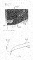
- Figure 2 schematically shows a cross-sectional view of the tip 108 and the inner wall 109 of the valve seat 107.
- Figure 2 only shows one half of the complete cross-section. The other half is designed correspondingly.
- the tip 108 comprises the shape of a sphere.
- the tip 108 of the valve needle 102 has the form of a ball with a round outer surface.
- the inner wall 109 of the valve seat 107 faces the tip 108.
- the inner wall 109 comprises a projecting part 110.
- the projecting part 110 has a surface that is in contact with the tip 108 in the closed position.
- the projecting part 110 is arranged between a first recessed part 111 and a second recessed part 112 along a transverse direction 114. Beginning at the central longitudinal axis 105, along the direction 114 the first recessed part 111 is arranged first, then the projecting part 110 and then the second recessed part 112 behind the projecting part 110.
- the projecting part 110 comprises the form of a sphere, especially a sphere segment.
- the inner wall 109 is formed convex in the projecting part 110.
- the inner wall 109 extends outward in the projecting part 110.
- the inner wall 109 hollows inward in the recessed parts 111 and 112.
- the tip 108 that has the shape of a sphere and the inner wall 109 in the projecting part 110 that has a shape of a torus segment are in contact with each other.
- the geometry of the valve seat 107, especially of the inner wall 109, at the projecting part 110 comprises an annular ring with the shape of approximately one quarter of the torus to form the convex shape.
- the use of the tip 108 with the shape of a sphere and the valve seat 107 with the convex inner wall 109 allows a desired sealing.
- the leakage of the injector 100 is reduced when compared to conventional injectors that have a flat or cone-shaped inner wall, which is in contact with the tip of the valve needle.
- the projecting part 110 of the inner wall 109 it is possible to have a tip leakage in the closed position below 1 mm 3 per minute at 50 bar in standard test fluid.
- the projecting part 110 of the inner wall 109 it is possible to have a tip leakage in the closed position below 1 mm 3 per minute with a minimum process capability index of 2.
- the contact area established under a certain load between the tip 108 and the inner wall 109 is smaller than the area established under a same load by conventional injectors.
- the contact area is approximately 30% less in the case of the same radius for the tip 108 and the valve seat 107.
- the contact pressure between the valve seat 107 and the tip 108 is higher and the sealing is better.
- the injector 100 it is possible to increase the maximum working pressure of the injector 100. It is possible to reduce the spring load of the spring element 113 without worsening the tip sealing performances due to the increased contact pressure that is achieved by the convex shape of the projecting part 110. For example, it is possible to reduce the spring load by approximately 30% and in doing so having the same sealing and leakage as conventional injectors. On the other hand it is possible to have a reduced leakage with the same spring load as with conventional injectors. For example, it is possible to have sufficient sealing performances with a reduced spring load and hence have an increased maximum working pressure of 50 bar compared to conventional injectors.
- the tip 108 has a spherical shape and the projecting part 110 has the shape of the torus segment. Therefore, the contact is in theory just one point or a circular line respectively.
- the contact pressure between the tip 108 and the valve seat 107 is high. Due to the high contact pressure it is possible to use cheaper materials with a lower quality, for example with a higher roughness at the surfaces before the run-in. During the run-in with the high contact pressure between the valve seat 107 and the tip 108 the deformation of the contact areas is fast and efficient and thus the roughness is sufficiently compensated.
- Figure 3 shows a diagram that compares the contact area of the injector 100 according to the present application with the contact area of a conventional injector.
- the curve 201 shows the contact area of the conventional injector that has a flat inner wall of the valve seat.
- the inner wall of the conventional injector comprises the shape of a cone segment especially at the area, where the tip of the valve needle contacts the inner wall in the closed position. With higher forces, the contact area increases very fast.
- a curve 202 shows the contact area of the injector 100 with the projecting part 110 of the inner wall 109.
- the contact area between the valve seat 107 and the tip 108 increases to a lesser extent when the force increases compared to the conventional injector.
- the sphere to torus type of interaction between the valve seat 107 and the tip 108 leads to a reduction of the tip leak due to the higher contact pressure between the ball of the tip 108 and the inner wall 109 of the valve seat 107. Furthermore, a higher correlation between the micro-profiles of the tip 108 and the inner wall 109 is achieved, in particular under plastic deformation. During run-in, a faster and more effective plastic shape adjustment of the inner wall 109 and the tip 108 is possible.
Landscapes
- Engineering & Computer Science (AREA)
- Chemical & Material Sciences (AREA)
- Combustion & Propulsion (AREA)
- Mechanical Engineering (AREA)
- General Engineering & Computer Science (AREA)
- Physics & Mathematics (AREA)
- Electromagnetism (AREA)
- Fuel-Injection Apparatus (AREA)
Abstract
- the injector body (5) extending between a fluid outlet end (5a) and a fluid inlet end (5b) along a central longitudinal axis (3) and having a cavity (7) and a valve seat,
- the valve needle (9) being arranged axially movable relative to the injector body (5) in the cavity (7), being operable to seal the injector in a closed position, in which a tip of the valve needle is in contact with the valve seat, and being axially displaceable away from the closed position to unseal the injector, and
- the valve seat comprising an inner wall facing the tip, the inner wall comprising a projecting part with a convex shape.
Description
- The invention relates to an injector for injecting fluid and particularly relates to an injector for injecting fuel into an internal combustion engine.
- Injectors are in widespread use, in particular for internal combustion engines where they may be arranged in order to dose the fluid into an intake manifold of the internal combustion engine or directly into the combustion chamber of a cylinder of the internal combustion engine.
- Injectors may be also called injections valves and are manufactured in various forms in order to satisfy the various needs for the various combustion engines. Therefore, for example, their length, diameter as well as various elements of the injector, which are responsible for the way the fluid is dosed, may vary within a wide range. In addition to that, injectors may accommodate an actuator for actuating a valve needle, which may, for example, be an electromagnetic actuator.
- In order to enhance the combustion process with regard to the reduction of unwanted emissions, the respective injection valve may be suited to dose fluids under very high pressure. The pressure may be, for example in the case of a gasoline engine, in the range of up to 400 bar, and in the case of diesel engines in the range of up to 3,500 bar.
- One object of the invention is to create an injector for injecting fluid that contributes to a precise and reliable injection of fluid.
- According to an aspect of the invention, an injector for injecting fluid comprises an injector body and a valve needle. The injector body extends between a fluid outlet end and a fluid inlet end along a central longitudinal axis. The injector body has a cavity and a valve seat. The valve needle is arranged axially movable relative to the injector body in the cavity. The valve needle is operable to seal the injector in a closed position in which a tip of the valve needle is in contact with the valve seat. The valve needle is axially displaceable away from the closed position to unseal the injector. The valve seat comprises an inner wall facing the tip. The inner wall comprises a projecting part with a convex shape.
- The injector has a leakage even in the closed position. This leakage should be reduced to a given value. Therefore, the inner wall of the valve seat comprises the projecting part with the convex shape. The geometry of the inner wall has an annular ring that forms the convex shape. Hence, the contact area of the tip of the valve needle and the valve seat is small, in particular smaller than in conventional injectors that have a flat inner wall of the valve seat.
- The smaller contact area of the inner wall with the convex shape with the tip of the valve needle allows a higher contact pressure at an equivalent load. This leads to a better sealing and to a reduced leakage. Further, the higher contact pressure allows a fast and effective plastic shape adjustment during run-in. The run-in is conducted at the factory for each injector before delivery to a customer.
- For example, it is possible to have better tip seal results due to the higher contact pressure. Alternatively or in addition, it is possible to have a shorter run-in because less cycles are necessary to have a sufficient plastic shape adjustment.
- Particularly, the projecting part comprises a shape of a torus segment. For example, the geometry of the inner wall comprises a shape of approximately one quarter of a torus in a cross-section along the longitudinal axis.
- According to further embodiments the injector body comprises a first recessed part with a concave shape. The first recessed part is arranged outwards besides the projecting part.
- Alternatively or in addition, according to further embodiments, the injector body comprises a second recessed part with a concave shape. The second recessed part is arranged inwards beside the projecting part. In particular, the projecting part is arranged between the first recessed part and the second recessed part in a direction transverse to the longitudinal axis.
- According to further embodiments, the injector comprises a spring element with a given spring force. The spring element is arranged to exert a preload force on the valve needle to urge the valve needle in the closed position. The spring force is given dependent on the convex shape. Due to the convex shape of the inner wall, it is possible to reduce the preload force of the spring element due to the increased contact pressure. The tip sealing performance remains the same compared to conventional injectors even with a reduced spring load when the inner wall comprises the projecting part with the convex shape.
- According to further embodiments, the tip of the valve needle comprises a shape of a sphere segment. For example, the tip of the valve needle is formed as at least a part of a sphere or a ball. When the tip comprises the shape of the sphere segment at least in the area where it is in contact with the valve seat in the closed position, the contact pressure between the tip and the valve seat is small and hence the contact pressure is as high as desired.
- Various embodiments of the present invention will be described with reference to the attached drawings. Elements of the same construction or function can have the same reference sign throughout the figures.
-
Figure 1 schematically shows an injector according to an embodiment; -
Figure 2 schematically shows a cross-sectional view of a detail of the injector according to an embodiment; and -
Figure 3 schematically shows a diagram of contact areas according an embodiment. -
Figure 1 schematically shows aninjector 100 for injecting fuel. Particularly, theinjector 100 is designed for injecting fuel into a cylinder of an internal combustion engine of a vehicle and particularly an automobile. Thefluid injector 100 has alongitudinal axis 105 and extends between a fluid inlet end 104 and afluid outlet end 103 of aninjector body 101. Theinjector body 101 surrounds acavity 106. A valve needle 102 is arranged in thecavity 106. The valve needle 102 is axially movable with respect to theinjector body 101. - The injector body 102 comprises a
valve seat 107 that is arranged at thefluid outlet end 103. Further details of thevalve seat 107 are explained with respect toFigure 2 below. - The valve needle 102 comprises a
tip 108. Thetip 108 faces thevalve seat 107 at thefluid outlet end 103. Thetip 108 is formed as a ball. - In a closed position of the
injector 100, in which a fluid flow through theinjector 100 is inhibited, thetip 108 of the valve needle 102 sealingly rests on thevalve seat 107. When thetip 108 is in contact with thevalve seat 107, particularly with an inner wall 109 (Figure 2 ) of thevalve seat 107 in a closed position, a fluid flow through an injector nozzle (not explicitly shown) at thevalve seat 107 is prevented. A fluid injector through the injector nozzle is permitted when the valve needle 102 is in further positions in which thetip 108 is spaced apart from theinner wall 109. - The
injector 100 may comprise an electromagnetic actuator or a piezo actuator for moving the valve needle 102 along thelongitudinal axis 105 in at least one direction. - A
spring element 113 is arranged for moving the valve needle 102 in the opposite direction. The valve needle is pressed against thevalve seat 107 by thespring element 113, when the actuator is not energized. -
Figure 2 schematically shows a cross-sectional view of thetip 108 and theinner wall 109 of thevalve seat 107.Figure 2 only shows one half of the complete cross-section. The other half is designed correspondingly. - The
tip 108 comprises the shape of a sphere. In particular, thetip 108 of the valve needle 102 has the form of a ball with a round outer surface. - The
inner wall 109 of thevalve seat 107 faces thetip 108. Theinner wall 109 comprises a projecting part 110. The projecting part 110 has a surface that is in contact with thetip 108 in the closed position. The projecting part 110 is arranged between a first recessed part 111 and a second recessed part 112 along a transverse direction 114. Beginning at the centrallongitudinal axis 105, along the direction 114 the first recessed part 111 is arranged first, then the projecting part 110 and then the second recessed part 112 behind the projecting part 110. - The projecting part 110 comprises the form of a sphere, especially a sphere segment. The
inner wall 109 is formed convex in the projecting part 110. Theinner wall 109 extends outward in the projecting part 110. Theinner wall 109 hollows inward in the recessed parts 111 and 112. - In the closed position the
tip 108 that has the shape of a sphere and theinner wall 109 in the projecting part 110 that has a shape of a torus segment are in contact with each other. The geometry of thevalve seat 107, especially of theinner wall 109, at the projecting part 110 comprises an annular ring with the shape of approximately one quarter of the torus to form the convex shape. Hence, for sealing theinjector 100 thetip 108 is pressed against the projecting part 110 by thebias spring element 113. Additionally, the hydraulic load of the fluid may press thetip 108 against the projecting part 110. - The use of the
tip 108 with the shape of a sphere and thevalve seat 107 with the convexinner wall 109 allows a desired sealing. For example, the leakage of theinjector 100 is reduced when compared to conventional injectors that have a flat or cone-shaped inner wall, which is in contact with the tip of the valve needle. For example, with the projecting part 110 of theinner wall 109 it is possible to have a tip leakage in the closed position below 1 mm3 per minute at 50 bar in standard test fluid. For example, with the projecting part 110 of theinner wall 109 it is possible to have a tip leakage in the closed position below 1 mm3 per minute with a minimum process capability index of 2. - The contact area established under a certain load between the
tip 108 and theinner wall 109 is smaller than the area established under a same load by conventional injectors. For example, the contact area is approximately 30% less in the case of the same radius for thetip 108 and thevalve seat 107. The contact pressure between thevalve seat 107 and thetip 108 is higher and the sealing is better. - During run-in of the
injector 100 the higher contact pressure of thetip 108 at the projecting part 110 at the equivalent load leads to a faster and effective plastic shape adjustment compared to conventional injectors. For example, it is possible to reduce the run-in cycles and have the same sealing result. On the other hand it is possible to have the same cycles for run-in and have better sealing results. - Furthermore, it is possible to increase the maximum working pressure of the
injector 100. It is possible to reduce the spring load of thespring element 113 without worsening the tip sealing performances due to the increased contact pressure that is achieved by the convex shape of the projecting part 110. For example, it is possible to reduce the spring load by approximately 30% and in doing so having the same sealing and leakage as conventional injectors. On the other hand it is possible to have a reduced leakage with the same spring load as with conventional injectors. For example, it is possible to have sufficient sealing performances with a reduced spring load and hence have an increased maximum working pressure of 50 bar compared to conventional injectors. - In theory the
tip 108 has a spherical shape and the projecting part 110 has the shape of the torus segment. Therefore, the contact is in theory just one point or a circular line respectively. Hence, the contact pressure between thetip 108 and thevalve seat 107 is high. Due to the high contact pressure it is possible to use cheaper materials with a lower quality, for example with a higher roughness at the surfaces before the run-in. During the run-in with the high contact pressure between thevalve seat 107 and thetip 108 the deformation of the contact areas is fast and efficient and thus the roughness is sufficiently compensated. -
Figure 3 shows a diagram that compares the contact area of theinjector 100 according to the present application with the contact area of a conventional injector. Thecurve 201 shows the contact area of the conventional injector that has a flat inner wall of the valve seat. For example, the inner wall of the conventional injector comprises the shape of a cone segment especially at the area, where the tip of the valve needle contacts the inner wall in the closed position. With higher forces, the contact area increases very fast. - A
curve 202 shows the contact area of theinjector 100 with the projecting part 110 of theinner wall 109. The contact area between thevalve seat 107 and thetip 108 increases to a lesser extent when the force increases compared to the conventional injector. - The sphere to torus type of interaction between the
valve seat 107 and thetip 108 leads to a reduction of the tip leak due to the higher contact pressure between the ball of thetip 108 and theinner wall 109 of thevalve seat 107. Furthermore, a higher correlation between the micro-profiles of thetip 108 and theinner wall 109 is achieved, in particular under plastic deformation. During run-in, a faster and more effective plastic shape adjustment of theinner wall 109 and thetip 108 is possible. -
- 100
- Injector
- 101
- valve body
- 102
- valve needle
- 103
- fluid outlet end
- 104
- fluid inlet end
- 105
- central longitudinal axis
- 106
- cavity
- 107
- valve seat
- 108
- tip
- 109
- inner wall
- 110
- projecting part
- 111
- first recessed part
- 112
- second recessed part
- 113
- spring element
- 114
- transverse direction
- 201
- curve
- 202
- curve
Claims (7)
- Injector (1) for injecting fluid comprising an injector body (5) and a valve needle (9),- the injector body (5) extending between a fluid outlet end (5a) and a fluid inlet end (5b) along a central longitudinal axis (3) and having a cavity (7) and a valve seat,- the valve needle (9) being arranged axially movable relative to the injector body (5) in the cavity (7), being operable to seal the injector in a closed position, in which a tip of the valve needle is in contact with the valve seat, and being axially displaceable away from the closed position to unseal the injector, and- the valve seat comprising an inner wall facing the tip, the inner wall comprising a projecting part with a convex shape.
- Injector according to claim 1, wherein the projecting part comprises a shape of a torus segment.
- Injector according to claim 1 or 2, the injector body comprising a first recessed part with a concave shape, the first recessed part being arranged outwards besides the projecting part.
- Injector according to any of claims 1 to 3, the injector body comprising a second recessed part with a concave shape, the second recessed part being arranged inwards besides the projecting part.
- Injector according to claims 3 and 4, the projecting part being arranged between the first recessed part and the second recessed part.
- Injector according to any of claims 1 to 5, comprising- a spring element (SE) with a given spring force being arranged to exert a preload force (PF) on the valve needle (VN) acting to urge the valve needle (VN) in the closed position, the spring force being given dependent on the convex shape.
- Injector according to any of claims 1 to 6, wherein the tip of the valve needle comprises a shape of a sphere segment.
Priority Applications (1)
| Application Number | Priority Date | Filing Date | Title |
|---|---|---|---|
| EP15189699.0A EP3156641A1 (en) | 2015-10-14 | 2015-10-14 | Injector for injecting fluid |
Applications Claiming Priority (1)
| Application Number | Priority Date | Filing Date | Title |
|---|---|---|---|
| EP15189699.0A EP3156641A1 (en) | 2015-10-14 | 2015-10-14 | Injector for injecting fluid |
Publications (1)
| Publication Number | Publication Date |
|---|---|
| EP3156641A1 true EP3156641A1 (en) | 2017-04-19 |
Family
ID=54324875
Family Applications (1)
| Application Number | Title | Priority Date | Filing Date |
|---|---|---|---|
| EP15189699.0A Ceased EP3156641A1 (en) | 2015-10-14 | 2015-10-14 | Injector for injecting fluid |
Country Status (1)
| Country | Link |
|---|---|
| EP (1) | EP3156641A1 (en) |
Citations (9)
| Publication number | Priority date | Publication date | Assignee | Title |
|---|---|---|---|---|
| DE19726991A1 (en) * | 1997-06-25 | 1999-01-07 | Bosch Gmbh Robert | Valve and method for manufacturing a valve seat for a valve |
| EP1321661A2 (en) * | 2001-12-22 | 2003-06-25 | Robert Bosch Gmbh | Fuel injection valve for internal combustion engines |
| DE10307932A1 (en) * | 2003-02-25 | 2004-10-28 | Robert Bosch Gmbh | Fuel injection valve for petrol engine, has valve plug with end surface facing valve seat with groove including array of spray openings |
| DE10341790A1 (en) * | 2003-09-10 | 2005-04-21 | Bosch Gmbh Robert | Fuel injector valve and nozzle for internal combustion engine has electromagnetic coil moving valve needle with spherical end engaging nozzle lining with thickened portions round nozzle bores |
| DE102004050046A1 (en) * | 2004-10-14 | 2006-04-20 | Robert Bosch Gmbh | Fuel injection valve for internal combustion engines |
| DE102007013247A1 (en) * | 2007-03-20 | 2008-09-25 | Robert Bosch Gmbh | Sealing edge for conical seat valve |
| US20090090794A1 (en) * | 2007-10-04 | 2009-04-09 | Visteon Global Technologies, Inc. | Low pressure fuel injector |
| DE102008054840A1 (en) * | 2007-12-21 | 2009-06-25 | Robert Bosch Gmbh | Fuel injector |
| DE112013004206T5 (en) * | 2012-08-27 | 2015-06-25 | Hitachi Automotive Systems, Ltd. | Fuel injection valve |
-
2015
- 2015-10-14 EP EP15189699.0A patent/EP3156641A1/en not_active Ceased
Patent Citations (9)
| Publication number | Priority date | Publication date | Assignee | Title |
|---|---|---|---|---|
| DE19726991A1 (en) * | 1997-06-25 | 1999-01-07 | Bosch Gmbh Robert | Valve and method for manufacturing a valve seat for a valve |
| EP1321661A2 (en) * | 2001-12-22 | 2003-06-25 | Robert Bosch Gmbh | Fuel injection valve for internal combustion engines |
| DE10307932A1 (en) * | 2003-02-25 | 2004-10-28 | Robert Bosch Gmbh | Fuel injection valve for petrol engine, has valve plug with end surface facing valve seat with groove including array of spray openings |
| DE10341790A1 (en) * | 2003-09-10 | 2005-04-21 | Bosch Gmbh Robert | Fuel injector valve and nozzle for internal combustion engine has electromagnetic coil moving valve needle with spherical end engaging nozzle lining with thickened portions round nozzle bores |
| DE102004050046A1 (en) * | 2004-10-14 | 2006-04-20 | Robert Bosch Gmbh | Fuel injection valve for internal combustion engines |
| DE102007013247A1 (en) * | 2007-03-20 | 2008-09-25 | Robert Bosch Gmbh | Sealing edge for conical seat valve |
| US20090090794A1 (en) * | 2007-10-04 | 2009-04-09 | Visteon Global Technologies, Inc. | Low pressure fuel injector |
| DE102008054840A1 (en) * | 2007-12-21 | 2009-06-25 | Robert Bosch Gmbh | Fuel injector |
| DE112013004206T5 (en) * | 2012-08-27 | 2015-06-25 | Hitachi Automotive Systems, Ltd. | Fuel injection valve |
Similar Documents
| Publication | Publication Date | Title |
|---|---|---|
| US20170321636A1 (en) | Gas injector including an outwardly opening valve closure element | |
| US10094348B2 (en) | Valve assembly arrangement for an injection valve and injection valve | |
| EP2103804A1 (en) | Coupling arrangement | |
| US20080173734A1 (en) | Fuel injection device inhibiting abrasion | |
| US6666388B2 (en) | Plug pin for an internal combustion engine fuel injector nozzle | |
| US6789783B2 (en) | Fuel injection valve for internal combustion engines | |
| JP2004502074A (en) | Fuel injection valve for internal combustion engine | |
| CN105020057A (en) | Directly injecting gas valve | |
| CN102625878B (en) | fuel injection valve | |
| KR102274062B1 (en) | Nozzle assembly for a fuel injector, and fuel injector | |
| CN102282354A (en) | Fuel injectors for internal combustion engines | |
| US9394868B2 (en) | Valve assembly and injection valve | |
| EP2905457B1 (en) | Valve assembly and fluid injector for a combustion engine | |
| US8689760B1 (en) | Control valve | |
| EP3156641A1 (en) | Injector for injecting fluid | |
| US10519910B2 (en) | Valve for metering a fluid, especially a fuel injector | |
| KR101950577B1 (en) | Valve assembly comprising a valve closure member with an elastomeric seal and fluid injector | |
| US20060138255A1 (en) | Injector | |
| US10330062B2 (en) | Injector for injecting fluid | |
| JP6409068B2 (en) | Fuel injection nozzle | |
| JP2008008281A (en) | Fuel injection valve | |
| KR102082589B1 (en) | Piezoelectric Injectors for Fuel Injection | |
| US20160230723A1 (en) | Fuel Injector and Fuel-Injection System | |
| US9624885B2 (en) | Valve assembly with a guiding element and fluid injector | |
| US10570864B2 (en) | Fluid-injection device for internal combustion engines |
Legal Events
| Date | Code | Title | Description |
|---|---|---|---|
| PUAI | Public reference made under article 153(3) epc to a published international application that has entered the european phase |
Free format text: ORIGINAL CODE: 0009012 |
|
| AK | Designated contracting states |
Kind code of ref document: A1 Designated state(s): AL AT BE BG CH CY CZ DE DK EE ES FI FR GB GR HR HU IE IS IT LI LT LU LV MC MK MT NL NO PL PT RO RS SE SI SK SM TR |
|
| AX | Request for extension of the european patent |
Extension state: BA ME |
|
| 17P | Request for examination filed |
Effective date: 20171019 |
|
| RBV | Designated contracting states (corrected) |
Designated state(s): AL AT BE BG CH CY CZ DE DK EE ES FI FR GB GR HR HU IE IS IT LI LT LU LV MC MK MT NL NO PL PT RO RS SE SI SK SM TR |
|
| 17Q | First examination report despatched |
Effective date: 20181106 |
|
| RAP1 | Party data changed (applicant data changed or rights of an application transferred) |
Owner name: VITESCO TECHNOLOGIES GMBH |
|
| STAA | Information on the status of an ep patent application or granted ep patent |
Free format text: STATUS: THE APPLICATION HAS BEEN REFUSED |
|
| 18R | Application refused |
Effective date: 20200906 |