EP3156629A1 - Sensor snubber block for a gas turbine engine - Google Patents
Sensor snubber block for a gas turbine engine Download PDFInfo
- Publication number
- EP3156629A1 EP3156629A1 EP16193544.0A EP16193544A EP3156629A1 EP 3156629 A1 EP3156629 A1 EP 3156629A1 EP 16193544 A EP16193544 A EP 16193544A EP 3156629 A1 EP3156629 A1 EP 3156629A1
- Authority
- EP
- European Patent Office
- Prior art keywords
- snubber block
- sensor
- fuel
- manifold
- recited
- Prior art date
- Legal status (The legal status is an assumption and is not a legal conclusion. Google has not performed a legal analysis and makes no representation as to the accuracy of the status listed.)
- Granted
Links
Images




Classifications
-
- F—MECHANICAL ENGINEERING; LIGHTING; HEATING; WEAPONS; BLASTING
- F02—COMBUSTION ENGINES; HOT-GAS OR COMBUSTION-PRODUCT ENGINE PLANTS
- F02C—GAS-TURBINE PLANTS; AIR INTAKES FOR JET-PROPULSION PLANTS; CONTROLLING FUEL SUPPLY IN AIR-BREATHING JET-PROPULSION PLANTS
- F02C7/00—Features, components parts, details or accessories, not provided for in, or of interest apart form groups F02C1/00 - F02C6/00; Air intakes for jet-propulsion plants
- F02C7/22—Fuel supply systems
- F02C7/222—Fuel flow conduits, e.g. manifolds
-
- F—MECHANICAL ENGINEERING; LIGHTING; HEATING; WEAPONS; BLASTING
- F02—COMBUSTION ENGINES; HOT-GAS OR COMBUSTION-PRODUCT ENGINE PLANTS
- F02C—GAS-TURBINE PLANTS; AIR INTAKES FOR JET-PROPULSION PLANTS; CONTROLLING FUEL SUPPLY IN AIR-BREATHING JET-PROPULSION PLANTS
- F02C7/00—Features, components parts, details or accessories, not provided for in, or of interest apart form groups F02C1/00 - F02C6/00; Air intakes for jet-propulsion plants
- F02C7/22—Fuel supply systems
- F02C7/232—Fuel valves; Draining valves or systems
-
- F—MECHANICAL ENGINEERING; LIGHTING; HEATING; WEAPONS; BLASTING
- F05—INDEXING SCHEMES RELATING TO ENGINES OR PUMPS IN VARIOUS SUBCLASSES OF CLASSES F01-F04
- F05D—INDEXING SCHEME FOR ASPECTS RELATING TO NON-POSITIVE-DISPLACEMENT MACHINES OR ENGINES, GAS-TURBINES OR JET-PROPULSION PLANTS
- F05D2220/00—Application
- F05D2220/30—Application in turbines
- F05D2220/32—Application in turbines in gas turbines
-
- F—MECHANICAL ENGINEERING; LIGHTING; HEATING; WEAPONS; BLASTING
- F05—INDEXING SCHEMES RELATING TO ENGINES OR PUMPS IN VARIOUS SUBCLASSES OF CLASSES F01-F04
- F05D—INDEXING SCHEME FOR ASPECTS RELATING TO NON-POSITIVE-DISPLACEMENT MACHINES OR ENGINES, GAS-TURBINES OR JET-PROPULSION PLANTS
- F05D2300/00—Materials; Properties thereof
- F05D2300/10—Metals, alloys or intermetallic compounds
- F05D2300/12—Light metals
- F05D2300/121—Aluminium
Definitions
- the present disclosure relates to a sensor for a gas turbine engine and, more particularly, to a snubber block to minimize pump pulsations to the sensor.
- Gas turbine engines such as those that power modem commercial and military aircraft, include a compressor section to pressurize a supply of air, a combustor section to burn a hydrocarbon fuel in the presence of the pressurized air, and a turbine section to extract energy from the resultant combustion gases and generate thrust.
- a fuel supply system for a gas turbine often includes multiple fuel supply manifolds that deliver fuel to multiple areas of the gas turbine engine.
- the main fuel manifold includes a fuel filter.
- the pressure differential between fuel going into the filter and fuel coming out is measured by the Fuel Filter Delta Pressure Sensor (FFDP).
- FFDP Fuel Filter Delta Pressure Sensor
- the FFDP sensor As the FFDP sensor is mounted to the fuel manifold, the FFDP sensor may be subject to fuel pump pressure pulsations through the internal passages of the fuel manifold. These pulsations generate a throbbing effect on the sensor's diaphragm that, over time, may result in failure.
- a snubber block can include a body with at least one passage with a respective flow restrictive orifice, the body operable to receive a sensor.
- a further embodiment of the present disclosure may include a male section that extends from the body, the male section receivable within a manifold.
- a further embodiment of any of the embodiments of the present disclosure may include, wherein a radial seal mounted to the male section.
- a further embodiment of any of the embodiments of the present disclosure may include, wherein a pinch seal mounted around the male section.
- a further embodiment of any of the embodiments of the present disclosure may include, wherein the male section is geometrically equivalent to a male section of a sensor that is receivable within the body.
- a further embodiment of any of the embodiments of the present disclosure may include, wherein the body defines a first and a second fastener aperture to mount the body to a fuel manifold.
- a further embodiment of any of the embodiments of the present disclosure may include, wherein the first and the second fastener aperture are geometrically arranged to be equivalent to a first and a second fastener aperture in the body to mount the sensor to the body.
- a manifold assembly for a gas turbine engine can include a fuel manifold; a snubber block mounted to the fuel manifold; and a sensor mounted to the snubber block.
- a further embodiment of any of the embodiments of the present disclosure may include, wherein the sensor is a Fuel Filter Delta Pressure Sensor.
- a further embodiment of any of the embodiments of the present disclosure may include, wherein at least one passage with a respective flow restrictive orifices.
- a further embodiment of any of the embodiments of the present disclosure may include, wherein the at least one passage is in communication with a fuel filter.
- a further embodiment of any of the embodiments of the present disclosure may include, wherein the fuel filter is mounted to the fuel manifold.
- a further embodiment of any of the embodiments of the present disclosure may include, wherein a first and a second flow passage with a respective flow restrictive orifice in each of the first and second passage, the first and second passage in communication with a fuel filter.
- a further embodiment of any of the embodiments of the present disclosure may include, wherein a first and a second fastener aperture to mount the snubber block to the fuel manifold is geometrically equivalent to a first and a second fastener aperture to mount the sensor to the snubber block.
- a further embodiment of any of the embodiments of the present disclosure may include, wherein an interface to mount the snubber block to the fuel manifold is geometrically equivalent to an interface to mount the sensor to the snubber block.
- a further embodiment of any of the embodiments of the present disclosure may include, wherein the snubber block is manufactured of aluminum.
- a method of assembling a sensor to a gas turbine engine according to another disclosed non-limiting embodiment of the present disclosure can include mounting a snubber block between a component of the gas turbine engine and a sensor.
- a further embodiment of any of the embodiments of the present disclosure may include, wherein the snubber block restricts a fuel flow to and from the sensor.
- a further embodiment of any of the embodiments of the present disclosure may include, wherein the snubber block restricts a fuel flow to and from the sensor and a fuel filter.
- a further embodiment of any of the embodiments of the present disclosure may include, wherein an interface between the snubber block and the component of the gas turbine engine is geometrically equivalent is geometrically equivalent to an interface between the snubber block and the sensor, the component of the gas turbine engine including a fuel manifold.
- FIG. 1 schematically illustrates a gas turbine engine 20.
- the gas turbine engine 20 is disclosed herein as a two-spool turbofan that generally incorporates a fan section 22, a compressor section 24, a combustor section 26 and a turbine section 28.
- Alternative engines might include an augmentor section among other systems or features.
- the fan section 22 drives air into the compressor section 24 and along a bypass flowpath while the compressor section 24 drives air along a core flowpath for compression and communication into the combustor section 26 then expansion through the turbine section 28.
- turbofan gas turbine engine in the disclosed non-limiting embodiment, it should be understood that the concepts described herein are not limited to use with turbofans as the teachings may be applied to other types of turbine engines, for example, but not limited to, a three-spool (plus fan) engine.
- the engine 20 generally includes a low spool 30 and a high spool 32 mounted for rotation about an engine central longitudinal axis A relative to an engine case structure 36 via several bearing structures 38.
- the low spool 30 generally includes an inner shaft 40 that interconnects a fan 42, a low pressure compressor (“LPC”) 44 and a low pressure turbine (“LPT”) 46.
- the inner shaft 40 drives the fan 42 directly or through a geared architecture 48 to drive the fan 42 at a lower speed than the low spool 30.
- An example reduction transmission is an epicyclic transmission, namely a planetary or star gear system.
- the high spool 32 includes an outer shaft 50 that interconnects a high pressure compressor (“HPC”) 52 and high pressure turbine (“HPT”) 54.
- a combustor 56 is arranged between the HPC 52 and the HPT 54.
- the inner shaft 40 and the outer shaft 50 are concentric and rotate about the engine central longitudinal axis A that is collinear with their longitudinal axes.
- Core airflow is compressed by the LPC 44 then the HPC 52, mixed with the fuel and burned in the combustor 56, then expanded through the HPT 54 and LPT 46.
- the LPT 46 and HPT 54 rotationally drive the respective low spool 30 and high spool 32 in response to the expansion.
- a manifold assembly 60 generally includes at least one fuel manifold 62, which may be a cast component such as that mounted to a diffuser case module 64 of the combustor 56.
- This cast manifold is an externally mounted manifold, which may be located according to externals architecture and packaging requirements. It should be appreciated that various other structures, such as Thermal Management Systems, Fuel Oil System manifolds and other fluid transport devices will benefit herefrom.
- the fuel manifold 62 may include a Fuel Filter Delta Pressure Sensor (FFDP Sensor) 70 that senses fuel flow through a fuel filter 72.
- FFDP Sensor Fuel Filter Delta Pressure Sensor
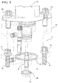
- the FFDP sensor 70 in the depicted embodiment is mounted to the fuel manifold 62 via a snubber block 74 (also shown in Figures 4 , 5 , 6A-6D , and 7 ).
- the FFDP sensor 70 is mounted to the snubber block 74 to minimize pressure pulsations communicated to the FFDP sensor 70.
- the snubber block 74 contains passages 76, 78 with respective flow restrictive orifices 80, 82 installed therein to reduce pump pulse sensations that may otherwise cause sensor failure. It should be appreciated that various flow restrictive orifices 80, 82 may be utilized depending upon, for example only, the source of the pulsations and the sensor.
- the passages 76, 78 ( Figure 5 ) may be cross-drilled or otherwise formed such as via additive manufacturing.
- the flow restrictive orifices 80, 82 dampen the effects of the pulsations on the FFDP Sensor 70 as the flow restrictive orifices 80, 82 restrict the respective high side and low side of the pressure gradient.
- the snubber block 74 is manufactured of aluminum or stainless steel.
- the snubber block 74 includes a body 83 from which extends a male section 84 that is shaped similar to a male end 86 of the sensor 70 such that the snubber block 74 installs into the fuel manifold 62 without modification thereto ( Figure 7 ). That is, in the disclosed embodiment, the interface between the snubber block 74 and the fuel manifold 62 is geometrically equivalent to the interface between the sensor 70 and the snubber block 74 such that a direct installation of the snubber block 74 is provided without modification to the fuel manifold 62.
- a radial seal 88 is located on the male section 84 of the snubber block 74 and an axial pinch seal 90 is mounted around the male section to seal with the surface of the fuel manifold 62 when the snubber block 74 is fastened to the fuel manifold via bolts 92, 94.
- a first and second aperture 96, 98 are arranged in the body 83 for respective bolts 92, 94 that are threaded into threaded apertures 100, 102 formed in the manifold 62 are geometrically arranged as are a first and second aperture 104, 106 in the sensor 70 for respective bolts 108, 110 that are threaded into threaded apertures 112, 114 formed in the snubber block 74. That is, the apertures are geometrically arranged such that the snubber block 74 is readily installed with minimal modification to either the sensor 70 or the manifold 62. For example the fuel manifold 62 may require only a more refined localized surface finish to facilitate an effective seal with the axial pinch seal 90.
- the snubber block 74 thereby reduces fuel pump pulse sensations to increase the service life of the sensor 70.
Landscapes
- Engineering & Computer Science (AREA)
- Chemical & Material Sciences (AREA)
- Combustion & Propulsion (AREA)
- Mechanical Engineering (AREA)
- General Engineering & Computer Science (AREA)
- Measuring Fluid Pressure (AREA)
Abstract
Description
- The present disclosure relates to a sensor for a gas turbine engine and, more particularly, to a snubber block to minimize pump pulsations to the sensor.
- Gas turbine engines, such as those that power modem commercial and military aircraft, include a compressor section to pressurize a supply of air, a combustor section to burn a hydrocarbon fuel in the presence of the pressurized air, and a turbine section to extract energy from the resultant combustion gases and generate thrust.
- A fuel supply system for a gas turbine often includes multiple fuel supply manifolds that deliver fuel to multiple areas of the gas turbine engine. The main fuel manifold includes a fuel filter. The pressure differential between fuel going into the filter and fuel coming out is measured by the Fuel Filter Delta Pressure Sensor (FFDP).
- As the FFDP sensor is mounted to the fuel manifold, the FFDP sensor may be subject to fuel pump pressure pulsations through the internal passages of the fuel manifold. These pulsations generate a throbbing effect on the sensor's diaphragm that, over time, may result in failure.
- A snubber block according to one disclosed non-limiting embodiment of the present disclosure can include a body with at least one passage with a respective flow restrictive orifice, the body operable to receive a sensor.
- A further embodiment of the present disclosure may include a male section that extends from the body, the male section receivable within a manifold.
- A further embodiment of any of the embodiments of the present disclosure may include, wherein a radial seal mounted to the male section.
- A further embodiment of any of the embodiments of the present disclosure may include, wherein a pinch seal mounted around the male section.
- A further embodiment of any of the embodiments of the present disclosure may include, wherein the male section is geometrically equivalent to a male section of a sensor that is receivable within the body.
- A further embodiment of any of the embodiments of the present disclosure may include, wherein the body defines a first and a second fastener aperture to mount the body to a fuel manifold.
- A further embodiment of any of the embodiments of the present disclosure may include, wherein the first and the second fastener aperture are geometrically arranged to be equivalent to a first and a second fastener aperture in the body to mount the sensor to the body.
- A manifold assembly for a gas turbine engine, according to another disclosed non-limiting embodiment of the present disclosure can include a fuel manifold; a snubber block mounted to the fuel manifold; and a sensor mounted to the snubber block.
- A further embodiment of any of the embodiments of the present disclosure may include, wherein the sensor is a Fuel Filter Delta Pressure Sensor.
- A further embodiment of any of the embodiments of the present disclosure may include, wherein at least one passage with a respective flow restrictive orifices.
- A further embodiment of any of the embodiments of the present disclosure may include, wherein the at least one passage is in communication with a fuel filter.
- A further embodiment of any of the embodiments of the present disclosure may include, wherein the fuel filter is mounted to the fuel manifold.
- A further embodiment of any of the embodiments of the present disclosure may include, wherein a first and a second flow passage with a respective flow restrictive orifice in each of the first and second passage, the first and second passage in communication with a fuel filter.
- A further embodiment of any of the embodiments of the present disclosure may include, wherein a first and a second fastener aperture to mount the snubber block to the fuel manifold is geometrically equivalent to a first and a second fastener aperture to mount the sensor to the snubber block.
- A further embodiment of any of the embodiments of the present disclosure may include, wherein an interface to mount the snubber block to the fuel manifold is geometrically equivalent to an interface to mount the sensor to the snubber block.
- A further embodiment of any of the embodiments of the present disclosure may include, wherein the snubber block is manufactured of aluminum.
- A method of assembling a sensor to a gas turbine engine according to another disclosed non-limiting embodiment of the present disclosure can include mounting a snubber block between a component of the gas turbine engine and a sensor.
- A further embodiment of any of the embodiments of the present disclosure may include, wherein the snubber block restricts a fuel flow to and from the sensor.
- A further embodiment of any of the embodiments of the present disclosure may include, wherein the snubber block restricts a fuel flow to and from the sensor and a fuel filter.
- A further embodiment of any of the embodiments of the present disclosure may include, wherein an interface between the snubber block and the component of the gas turbine engine is geometrically equivalent is geometrically equivalent to an interface between the snubber block and the sensor, the component of the gas turbine engine including a fuel manifold.
- The foregoing features and elements may be combined in various combinations without exclusivity, unless expressly indicated otherwise. These features and elements as well as the operation thereof will become more apparent in light of the following description and the accompanying drawings. It should be understood, however, the following description and drawings are intended to be exemplary in nature and non-limiting.
- Various features will become apparent to those skilled in the art from the following detailed description of the disclosed non-limiting embodiment. The drawings that accompany the detailed description can be briefly described as follows:
-
Figure 1 is a schematic cross-section of an example of a gas turbine engine; -
Figure 2 is a perspective view of an example fuel supply manifold assembly; -
Figure 3 is a schematic block view of a fuel supply manifold assembly with a snubber block according to one disclosed non-limiting embodiment; -
Figure 4 is a perspective view of the snubber block; -
Figure 5 is a partial phantom view of the snubber block; -
Figure 6A is a perspective view of the snubber block; -
Figure 6B is a sectional view of the snubber block; -
Figure 6C is a perspective view of the snubber block; -
Figure 6D is a sectional view of the snubber block transverse to the sectional view ofFigure 6B ; and -
Figure 7 is a sectional view of the snubber block installed in the manifold assembly. -
Figure 1 schematically illustrates agas turbine engine 20. Thegas turbine engine 20 is disclosed herein as a two-spool turbofan that generally incorporates afan section 22, acompressor section 24, acombustor section 26 and aturbine section 28. Alternative engines might include an augmentor section among other systems or features. Thefan section 22 drives air into thecompressor section 24 and along a bypass flowpath while thecompressor section 24 drives air along a core flowpath for compression and communication into thecombustor section 26 then expansion through theturbine section 28. Although depicted as a turbofan gas turbine engine in the disclosed non-limiting embodiment, it should be understood that the concepts described herein are not limited to use with turbofans as the teachings may be applied to other types of turbine engines, for example, but not limited to, a three-spool (plus fan) engine. - The
engine 20 generally includes alow spool 30 and ahigh spool 32 mounted for rotation about an engine central longitudinal axis A relative to anengine case structure 36 via several bearingstructures 38. Thelow spool 30 generally includes aninner shaft 40 that interconnects afan 42, a low pressure compressor ("LPC") 44 and a low pressure turbine ("LPT") 46. Theinner shaft 40 drives thefan 42 directly or through a gearedarchitecture 48 to drive thefan 42 at a lower speed than thelow spool 30. An example reduction transmission is an epicyclic transmission, namely a planetary or star gear system. - The
high spool 32 includes anouter shaft 50 that interconnects a high pressure compressor ("HPC") 52 and high pressure turbine ("HPT") 54. Acombustor 56 is arranged between theHPC 52 and theHPT 54. Theinner shaft 40 and theouter shaft 50 are concentric and rotate about the engine central longitudinal axis A that is collinear with their longitudinal axes. - Core airflow is compressed by the
LPC 44 then theHPC 52, mixed with the fuel and burned in thecombustor 56, then expanded through theHPT 54 andLPT 46. TheLPT 46 andHPT 54 rotationally drive the respectivelow spool 30 andhigh spool 32 in response to the expansion. - With reference to
Figure 2 , amanifold assembly 60 generally includes at least onefuel manifold 62, which may be a cast component such as that mounted to adiffuser case module 64 of thecombustor 56. This cast manifold is an externally mounted manifold, which may be located according to externals architecture and packaging requirements. It should be appreciated that various other structures, such as Thermal Management Systems, Fuel Oil System manifolds and other fluid transport devices will benefit herefrom. - With reference to
Figure 3 , thefuel manifold 62 may include a Fuel Filter Delta Pressure Sensor (FFDP Sensor) 70 that senses fuel flow through afuel filter 72. TheFFDP sensor 70 in the depicted embodiment is mounted to thefuel manifold 62 via a snubber block 74 (also shown inFigures 4 ,5 ,6A-6D , and7 ). TheFFDP sensor 70 is mounted to thesnubber block 74 to minimize pressure pulsations communicated to theFFDP sensor 70. - The
snubber block 74 containspassages restrictive orifices restrictive orifices passages 76, 78 (Figure 5 ) may be cross-drilled or otherwise formed such as via additive manufacturing. The flowrestrictive orifices FFDP Sensor 70 as the flowrestrictive orifices - With reference to
Figure 5 , in one embodiment, thesnubber block 74 is manufactured of aluminum or stainless steel. Thesnubber block 74 includes abody 83 from which extends amale section 84 that is shaped similar to amale end 86 of thesensor 70 such that thesnubber block 74 installs into thefuel manifold 62 without modification thereto (Figure 7 ). That is, in the disclosed embodiment, the interface between thesnubber block 74 and thefuel manifold 62 is geometrically equivalent to the interface between thesensor 70 and thesnubber block 74 such that a direct installation of thesnubber block 74 is provided without modification to thefuel manifold 62. - Various seals such as O-rings may be utilized to facilitate a seal of the fluid flow. In one embodiment, a
radial seal 88 is located on themale section 84 of thesnubber block 74 and anaxial pinch seal 90 is mounted around the male section to seal with the surface of thefuel manifold 62 when thesnubber block 74 is fastened to the fuel manifold viabolts - A first and
second aperture body 83 forrespective bolts apertures second aperture sensor 70 forrespective bolts apertures snubber block 74. That is, the apertures are geometrically arranged such that thesnubber block 74 is readily installed with minimal modification to either thesensor 70 or the manifold 62. For example thefuel manifold 62 may require only a more refined localized surface finish to facilitate an effective seal with theaxial pinch seal 90. - The
snubber block 74 thereby reduces fuel pump pulse sensations to increase the service life of thesensor 70. - The use of the terms "a," "an," "the," and similar references in the context of description (especially in the context of the following claims) are to be construed to cover both the singular and the plural, unless otherwise indicated herein or specifically contradicted by context. The modifier "about" used in connection with a quantity is inclusive of the stated value and has the meaning dictated by the context (e.g., it includes the degree of error associated with measurement of the particular quantity). All ranges disclosed herein are inclusive of the endpoints, and the endpoints are independently combinable with each other. It should be appreciated that relative positional terms such as "forward," "aft," "upper," "lower," "above," "below," and the like are with reference to normal operational attitude and should not be considered otherwise limiting.
- Although the different non-limiting embodiments have specific illustrated components, the embodiments of this invention are not limited to those particular combinations. It is possible to use some of the components or features from any of the non-limiting embodiments in combination with features or components from any of the other non-limiting embodiments.
- It should be appreciated that like reference numerals identify corresponding or similar elements throughout the several drawings. It should also be appreciated that although a particular component arrangement is disclosed in the illustrated embodiment, other arrangements will benefit herefrom.
- Although particular step sequences are shown, described, and claimed, it should be understood that steps may be performed in any order, separated or combined unless otherwise indicated and will still benefit from the present disclosure.
- The foregoing description is exemplary rather than defined by the limitations within. Various non-limiting embodiments are disclosed herein, however, one of ordinary skill in the art would recognize that various modifications and variations in light of the above teachings will fall within the scope of the appended claims. It is therefore to be understood that within the scope of the appended claims, the disclosure may be practiced other than as specifically described. For that reason the appended claims should be studied to determine true scope and content.
Claims (15)
- A snubber block, comprising:a body with at least one passage with a respective flow restrictive orifice, the body operable to receive a sensor.
- The snubber block as recited in claim 1, further comprising a male section that extends from the body, the male section receivable within a manifold.
- The snubber block as recited in claims 1 or 2, further comprising a radial seal mounted to the male section, and preferably further comprising a pinch seal mounted around the male section.
- The snubber block as recited in any preceding claim, wherein the male section is geometrically equivalent to a male section of a sensor that is receivable within the body.
- The snubber block as recited in any preceding claim, wherein the body defines a first and a second fastener aperture to mount the body to a fuel manifold, and preferably wherein the first and the second fastener aperture are geometrically arranged to be equivalent to a first and a second fastener aperture in the body to mount the sensor to the body.
- A manifold assembly for a gas turbine engine, comprising:a fuel manifold;a snubber block mounted to the fuel manifold; anda sensor mounted to the snubber block.
- The manifold assembly as recited in claim 6, wherein the sensor is a Fuel Filter Delta Pressure Sensor.
- The manifold assembly as recited in claims 6 or 7, further comprising at least one passage with a respective flow restrictive orifices, and preferably wherein the at least one passage is in communication with a fuel filter, and more preferably wherein the fuel filter is mounted to the fuel manifold.
- The manifold assembly as recited in any of claims 6-8, further comprising a first and a second flow passage with a respective flow restrictive orifice in each of the first and second passage, the first and second passage in communication with a fuel filter.
- The manifold assembly as recited in any of claims 6-9, wherein a first and a second fastener aperture to mount the snubber block to the fuel manifold is geometrically equivalent to a first and a second fastener aperture to mount the sensor to the snubber block.
- The manifold assembly as recited in any of claims 6-10, wherein an interface to mount the snubber block to the fuel manifold is geometrically equivalent to an interface to mount the sensor to the snubber block.
- A method of assembling a sensor to a gas turbine engine comprising:mounting a snubber block between a component of the gas turbine engine and a sensor.
- The method as recited in claim 12, wherein the snubber block restricts a fuel flow to and from the sensor.
- The method as recited in claim 12, wherein the snubber block restricts a fuel flow to and from the sensor and a fuel filter.
- The method as recited in claim 12, wherein an interface between the snubber block and the component of the gas turbine engine is geometrically equivalent is geometrically equivalent to an interface between the snubber block and the sensor, the component of the gas turbine engine including a fuel manifold.
Applications Claiming Priority (1)
| Application Number | Priority Date | Filing Date | Title |
|---|---|---|---|
| US201562240616P | 2015-10-13 | 2015-10-13 |
Publications (2)
| Publication Number | Publication Date |
|---|---|
| EP3156629A1 true EP3156629A1 (en) | 2017-04-19 |
| EP3156629B1 EP3156629B1 (en) | 2020-11-25 |
Family
ID=57137878
Family Applications (1)
| Application Number | Title | Priority Date | Filing Date |
|---|---|---|---|
| EP16193544.0A Active EP3156629B1 (en) | 2015-10-13 | 2016-10-12 | Sensor snubber block for a gas turbine engine and a corresponding method |
Country Status (2)
| Country | Link |
|---|---|
| US (1) | US11022041B2 (en) |
| EP (1) | EP3156629B1 (en) |
Cited By (3)
| Publication number | Priority date | Publication date | Assignee | Title |
|---|---|---|---|---|
| US11156164B2 (en) | 2019-05-21 | 2021-10-26 | General Electric Company | System and method for high frequency accoustic dampers with caps |
| US11174792B2 (en) | 2019-05-21 | 2021-11-16 | General Electric Company | System and method for high frequency acoustic dampers with baffles |
| US12312279B2 (en) | 2019-12-24 | 2025-05-27 | Rolls-Royce Corporation | Silica-rich barrier coatings |
Citations (7)
| Publication number | Priority date | Publication date | Assignee | Title |
|---|---|---|---|---|
| US4761957A (en) * | 1983-03-01 | 1988-08-09 | Solar Turbines Incorporated | Indirectly heated gas turbine engine |
| EP0428373A2 (en) * | 1989-11-13 | 1991-05-22 | Control Techtronics, Inc. | Acoustical burner control system and method |
| EP0953749A2 (en) * | 1998-04-29 | 1999-11-03 | General Electric Company | Pressure compensated fuel delivery system for the combustors of gas turbines |
| US20050284149A1 (en) * | 2004-06-18 | 2005-12-29 | Jansen Harvey B | Fuel control module |
| US20070130911A1 (en) * | 2005-12-13 | 2007-06-14 | Hamilton Sundstrand Corporation | Smart fuel control system |
| EP2031230A2 (en) * | 2007-08-31 | 2009-03-04 | Denso Corporation | Fuel injection characteristic sensing device and fuel injection command correcting device |
| EP2187023A1 (en) * | 2008-11-18 | 2010-05-19 | General Electric Company | Fuel control system for gas turbine and feed forward control method |
Family Cites Families (20)
| Publication number | Priority date | Publication date | Assignee | Title |
|---|---|---|---|---|
| US4582089A (en) * | 1984-10-31 | 1986-04-15 | General Screw Products Company | Valve manifold having a removable flange |
| US4920626A (en) * | 1989-04-07 | 1990-05-01 | Precision General, Inc. | Stabilized connector flange for interconnecting an instrument manifold with an orifice plate assembly |
| US5036884A (en) * | 1990-11-19 | 1991-08-06 | Keystone International Holdings Corp. | Mounting means for fluid pressure transmitters |
| GB9525370D0 (en) | 1995-12-12 | 1996-02-14 | Lucas Ind Plc | Flow sensor and fuel control system |
| DE19648689A1 (en) | 1996-11-25 | 1998-05-28 | Bosch Gmbh Robert | Method and device for testing and / or adjusting valves |
| US5895844A (en) | 1997-05-29 | 1999-04-20 | Outboard Marine Corporation | Precise fuel flow measurement with modified fluid control valve |
| US5987975A (en) | 1997-12-18 | 1999-11-23 | Rafei; Iraj | Machine lubrication system monitor |
| US6094904A (en) | 1998-07-16 | 2000-08-01 | United Technologies Corporation | Fuel injector with a replaceable sensor |
| DE50008726D1 (en) | 1999-08-21 | 2004-12-30 | Rolls Royce Deutschland | Method for adapting the operating state of a stepped combustion chamber for gas turbines |
| US6429020B1 (en) | 2000-06-02 | 2002-08-06 | The United States Of America As Represented By The United States Department Of Energy | Flashback detection sensor for lean premix fuel nozzles |
| US6672145B2 (en) | 2001-09-21 | 2004-01-06 | Honeywell International, Inc. | Apparatus and method for testing jet engine fuel manifold flow distribution |
| GB2385095B (en) * | 2002-01-23 | 2005-11-09 | Alstom | Fluidic apparatuses |
| US6996970B2 (en) * | 2003-09-30 | 2006-02-14 | Honeywell International Inc. | High accuracy fuel metering system for turbine engines |
| JP4059511B2 (en) | 2004-10-27 | 2008-03-12 | 株式会社デンソー | Flow rate measuring device and flow rate measuring method |
| US7637096B2 (en) | 2004-11-25 | 2009-12-29 | Rolls-Royce Plc | Pulse jet engine having pressure sensor means for controlling fuel delivery into a combustion chamber |
| US7784487B2 (en) | 2007-10-24 | 2010-08-31 | Honeywell International Inc. | Fuel metering valve assembly including thermal compensation mechanism |
| US20090114295A1 (en) * | 2007-11-06 | 2009-05-07 | Ultra Clean Holdings, Inc. | Gas-panel assembly |
| US8572985B2 (en) | 2009-06-26 | 2013-11-05 | Pratt & Whitney Canada Corp. | Air filtration system for gas turbine engine pneumatic system |
| US9133772B2 (en) | 2011-02-24 | 2015-09-15 | Hamilton Sundstrand Corporation | Fuel system |
| US8863580B2 (en) * | 2011-05-05 | 2014-10-21 | Rosemount Inc. | Process fluid pressure transmitter with replaceable atmospheric vent filter |
-
2016
- 2016-10-10 US US15/289,496 patent/US11022041B2/en active Active
- 2016-10-12 EP EP16193544.0A patent/EP3156629B1/en active Active
Patent Citations (7)
| Publication number | Priority date | Publication date | Assignee | Title |
|---|---|---|---|---|
| US4761957A (en) * | 1983-03-01 | 1988-08-09 | Solar Turbines Incorporated | Indirectly heated gas turbine engine |
| EP0428373A2 (en) * | 1989-11-13 | 1991-05-22 | Control Techtronics, Inc. | Acoustical burner control system and method |
| EP0953749A2 (en) * | 1998-04-29 | 1999-11-03 | General Electric Company | Pressure compensated fuel delivery system for the combustors of gas turbines |
| US20050284149A1 (en) * | 2004-06-18 | 2005-12-29 | Jansen Harvey B | Fuel control module |
| US20070130911A1 (en) * | 2005-12-13 | 2007-06-14 | Hamilton Sundstrand Corporation | Smart fuel control system |
| EP2031230A2 (en) * | 2007-08-31 | 2009-03-04 | Denso Corporation | Fuel injection characteristic sensing device and fuel injection command correcting device |
| EP2187023A1 (en) * | 2008-11-18 | 2010-05-19 | General Electric Company | Fuel control system for gas turbine and feed forward control method |
Cited By (3)
| Publication number | Priority date | Publication date | Assignee | Title |
|---|---|---|---|---|
| US11156164B2 (en) | 2019-05-21 | 2021-10-26 | General Electric Company | System and method for high frequency accoustic dampers with caps |
| US11174792B2 (en) | 2019-05-21 | 2021-11-16 | General Electric Company | System and method for high frequency acoustic dampers with baffles |
| US12312279B2 (en) | 2019-12-24 | 2025-05-27 | Rolls-Royce Corporation | Silica-rich barrier coatings |
Also Published As
| Publication number | Publication date |
|---|---|
| US20170101934A1 (en) | 2017-04-13 |
| US11022041B2 (en) | 2021-06-01 |
| EP3156629B1 (en) | 2020-11-25 |
Similar Documents
| Publication | Publication Date | Title |
|---|---|---|
| US9856746B2 (en) | Heatshield discourager seal for a gas turbine engine | |
| US9726031B2 (en) | Piston ring coated carbon seal | |
| US10352191B2 (en) | Gas turbine engine with air-oil cooler oil tank | |
| EP2809908B1 (en) | Mid-turbine frame buffer system | |
| US12168959B2 (en) | Gas turbine fan drive gear system | |
| US9016068B2 (en) | Mid-turbine frame with oil system mounts | |
| US20210017870A1 (en) | Curvic Seal for Gas Turbine Engine | |
| EP2880275B1 (en) | Forward compartment service system for a geared architecture gas turbine engine | |
| EP2971677B1 (en) | Triple flange arrangement for a gas turbine engine | |
| US10267406B2 (en) | Inseparable machined lubricant manifold | |
| US9765649B2 (en) | Borescope inspection port fitting | |
| US20130283756A1 (en) | Manifold for gas turbine engine | |
| EP3004568A2 (en) | Gas turbine engine with dove-tailed tobi vane | |
| US11022041B2 (en) | Sensor snubber block for a gas turbine engine | |
| US10156158B2 (en) | Integrated oil supply tube and check valve | |
| EP3470630A1 (en) | Double wall service tube with annular airflow passage | |
| US11066953B2 (en) | Multi-ply heat shield assembly with integral band clamp for a gas turbine engine |
Legal Events
| Date | Code | Title | Description |
|---|---|---|---|
| PUAI | Public reference made under article 153(3) epc to a published international application that has entered the european phase |
Free format text: ORIGINAL CODE: 0009012 |
|
| STAA | Information on the status of an ep patent application or granted ep patent |
Free format text: STATUS: THE APPLICATION HAS BEEN PUBLISHED |
|
| AK | Designated contracting states |
Kind code of ref document: A1 Designated state(s): AL AT BE BG CH CY CZ DE DK EE ES FI FR GB GR HR HU IE IS IT LI LT LU LV MC MK MT NL NO PL PT RO RS SE SI SK SM TR |
|
| AX | Request for extension of the european patent |
Extension state: BA ME |
|
| STAA | Information on the status of an ep patent application or granted ep patent |
Free format text: STATUS: REQUEST FOR EXAMINATION WAS MADE |
|
| 17P | Request for examination filed |
Effective date: 20171018 |
|
| RBV | Designated contracting states (corrected) |
Designated state(s): AL AT BE BG CH CY CZ DE DK EE ES FI FR GB GR HR HU IE IS IT LI LT LU LV MC MK MT NL NO PL PT RO RS SE SI SK SM TR |
|
| STAA | Information on the status of an ep patent application or granted ep patent |
Free format text: STATUS: EXAMINATION IS IN PROGRESS |
|
| 17Q | First examination report despatched |
Effective date: 20180921 |
|
| GRAP | Despatch of communication of intention to grant a patent |
Free format text: ORIGINAL CODE: EPIDOSNIGR1 |
|
| STAA | Information on the status of an ep patent application or granted ep patent |
Free format text: STATUS: GRANT OF PATENT IS INTENDED |
|
| INTG | Intention to grant announced |
Effective date: 20200103 |
|
| GRAJ | Information related to disapproval of communication of intention to grant by the applicant or resumption of examination proceedings by the epo deleted |
Free format text: ORIGINAL CODE: EPIDOSDIGR1 |
|
| STAA | Information on the status of an ep patent application or granted ep patent |
Free format text: STATUS: EXAMINATION IS IN PROGRESS |
|
| GRAP | Despatch of communication of intention to grant a patent |
Free format text: ORIGINAL CODE: EPIDOSNIGR1 |
|
| STAA | Information on the status of an ep patent application or granted ep patent |
Free format text: STATUS: GRANT OF PATENT IS INTENDED |
|
| INTC | Intention to grant announced (deleted) | ||
| INTG | Intention to grant announced |
Effective date: 20200519 |
|
| GRAS | Grant fee paid |
Free format text: ORIGINAL CODE: EPIDOSNIGR3 |
|
| GRAA | (expected) grant |
Free format text: ORIGINAL CODE: 0009210 |
|
| STAA | Information on the status of an ep patent application or granted ep patent |
Free format text: STATUS: THE PATENT HAS BEEN GRANTED |
|
| AK | Designated contracting states |
Kind code of ref document: B1 Designated state(s): AL AT BE BG CH CY CZ DE DK EE ES FI FR GB GR HR HU IE IS IT LI LT LU LV MC MK MT NL NO PL PT RO RS SE SI SK SM TR |
|
| REG | Reference to a national code |
Ref country code: GB Ref legal event code: FG4D |
|
| REG | Reference to a national code |
Ref country code: CH Ref legal event code: EP |
|
| REG | Reference to a national code |
Ref country code: AT Ref legal event code: REF Ref document number: 1338575 Country of ref document: AT Kind code of ref document: T Effective date: 20201215 |
|
| REG | Reference to a national code |
Ref country code: DE Ref legal event code: R096 Ref document number: 602016048455 Country of ref document: DE |
|
| REG | Reference to a national code |
Ref country code: IE Ref legal event code: FG4D |
|
| RAP2 | Party data changed (patent owner data changed or rights of a patent transferred) |
Owner name: RAYTHEON TECHNOLOGIES CORPORATION |
|
| REG | Reference to a national code |
Ref country code: AT Ref legal event code: MK05 Ref document number: 1338575 Country of ref document: AT Kind code of ref document: T Effective date: 20201125 |
|
| REG | Reference to a national code |
Ref country code: NL Ref legal event code: MP Effective date: 20201125 |
|
| PG25 | Lapsed in a contracting state [announced via postgrant information from national office to epo] |
Ref country code: GR Free format text: LAPSE BECAUSE OF FAILURE TO SUBMIT A TRANSLATION OF THE DESCRIPTION OR TO PAY THE FEE WITHIN THE PRESCRIBED TIME-LIMIT Effective date: 20210226 Ref country code: FI Free format text: LAPSE BECAUSE OF FAILURE TO SUBMIT A TRANSLATION OF THE DESCRIPTION OR TO PAY THE FEE WITHIN THE PRESCRIBED TIME-LIMIT Effective date: 20201125 Ref country code: NO Free format text: LAPSE BECAUSE OF FAILURE TO SUBMIT A TRANSLATION OF THE DESCRIPTION OR TO PAY THE FEE WITHIN THE PRESCRIBED TIME-LIMIT Effective date: 20210225 Ref country code: RS Free format text: LAPSE BECAUSE OF FAILURE TO SUBMIT A TRANSLATION OF THE DESCRIPTION OR TO PAY THE FEE WITHIN THE PRESCRIBED TIME-LIMIT Effective date: 20201125 Ref country code: PT Free format text: LAPSE BECAUSE OF FAILURE TO SUBMIT A TRANSLATION OF THE DESCRIPTION OR TO PAY THE FEE WITHIN THE PRESCRIBED TIME-LIMIT Effective date: 20210325 |
|
| PG25 | Lapsed in a contracting state [announced via postgrant information from national office to epo] |
Ref country code: AT Free format text: LAPSE BECAUSE OF FAILURE TO SUBMIT A TRANSLATION OF THE DESCRIPTION OR TO PAY THE FEE WITHIN THE PRESCRIBED TIME-LIMIT Effective date: 20201125 Ref country code: BG Free format text: LAPSE BECAUSE OF FAILURE TO SUBMIT A TRANSLATION OF THE DESCRIPTION OR TO PAY THE FEE WITHIN THE PRESCRIBED TIME-LIMIT Effective date: 20210225 Ref country code: IS Free format text: LAPSE BECAUSE OF FAILURE TO SUBMIT A TRANSLATION OF THE DESCRIPTION OR TO PAY THE FEE WITHIN THE PRESCRIBED TIME-LIMIT Effective date: 20210325 Ref country code: PL Free format text: LAPSE BECAUSE OF FAILURE TO SUBMIT A TRANSLATION OF THE DESCRIPTION OR TO PAY THE FEE WITHIN THE PRESCRIBED TIME-LIMIT Effective date: 20201125 Ref country code: LV Free format text: LAPSE BECAUSE OF FAILURE TO SUBMIT A TRANSLATION OF THE DESCRIPTION OR TO PAY THE FEE WITHIN THE PRESCRIBED TIME-LIMIT Effective date: 20201125 Ref country code: SE Free format text: LAPSE BECAUSE OF FAILURE TO SUBMIT A TRANSLATION OF THE DESCRIPTION OR TO PAY THE FEE WITHIN THE PRESCRIBED TIME-LIMIT Effective date: 20201125 |
|
| REG | Reference to a national code |
Ref country code: LT Ref legal event code: MG9D |
|
| PG25 | Lapsed in a contracting state [announced via postgrant information from national office to epo] |
Ref country code: HR Free format text: LAPSE BECAUSE OF FAILURE TO SUBMIT A TRANSLATION OF THE DESCRIPTION OR TO PAY THE FEE WITHIN THE PRESCRIBED TIME-LIMIT Effective date: 20201125 |
|
| PG25 | Lapsed in a contracting state [announced via postgrant information from national office to epo] |
Ref country code: CZ Free format text: LAPSE BECAUSE OF FAILURE TO SUBMIT A TRANSLATION OF THE DESCRIPTION OR TO PAY THE FEE WITHIN THE PRESCRIBED TIME-LIMIT Effective date: 20201125 Ref country code: EE Free format text: LAPSE BECAUSE OF FAILURE TO SUBMIT A TRANSLATION OF THE DESCRIPTION OR TO PAY THE FEE WITHIN THE PRESCRIBED TIME-LIMIT Effective date: 20201125 Ref country code: LT Free format text: LAPSE BECAUSE OF FAILURE TO SUBMIT A TRANSLATION OF THE DESCRIPTION OR TO PAY THE FEE WITHIN THE PRESCRIBED TIME-LIMIT Effective date: 20201125 Ref country code: SM Free format text: LAPSE BECAUSE OF FAILURE TO SUBMIT A TRANSLATION OF THE DESCRIPTION OR TO PAY THE FEE WITHIN THE PRESCRIBED TIME-LIMIT Effective date: 20201125 Ref country code: SK Free format text: LAPSE BECAUSE OF FAILURE TO SUBMIT A TRANSLATION OF THE DESCRIPTION OR TO PAY THE FEE WITHIN THE PRESCRIBED TIME-LIMIT Effective date: 20201125 Ref country code: RO Free format text: LAPSE BECAUSE OF FAILURE TO SUBMIT A TRANSLATION OF THE DESCRIPTION OR TO PAY THE FEE WITHIN THE PRESCRIBED TIME-LIMIT Effective date: 20201125 |
|
| REG | Reference to a national code |
Ref country code: DE Ref legal event code: R097 Ref document number: 602016048455 Country of ref document: DE |
|
| PG25 | Lapsed in a contracting state [announced via postgrant information from national office to epo] |
Ref country code: DK Free format text: LAPSE BECAUSE OF FAILURE TO SUBMIT A TRANSLATION OF THE DESCRIPTION OR TO PAY THE FEE WITHIN THE PRESCRIBED TIME-LIMIT Effective date: 20201125 |
|
| PLBE | No opposition filed within time limit |
Free format text: ORIGINAL CODE: 0009261 |
|
| STAA | Information on the status of an ep patent application or granted ep patent |
Free format text: STATUS: NO OPPOSITION FILED WITHIN TIME LIMIT |
|
| PG25 | Lapsed in a contracting state [announced via postgrant information from national office to epo] |
Ref country code: NL Free format text: LAPSE BECAUSE OF FAILURE TO SUBMIT A TRANSLATION OF THE DESCRIPTION OR TO PAY THE FEE WITHIN THE PRESCRIBED TIME-LIMIT Effective date: 20201125 Ref country code: IT Free format text: LAPSE BECAUSE OF FAILURE TO SUBMIT A TRANSLATION OF THE DESCRIPTION OR TO PAY THE FEE WITHIN THE PRESCRIBED TIME-LIMIT Effective date: 20201125 Ref country code: AL Free format text: LAPSE BECAUSE OF FAILURE TO SUBMIT A TRANSLATION OF THE DESCRIPTION OR TO PAY THE FEE WITHIN THE PRESCRIBED TIME-LIMIT Effective date: 20201125 |
|
| 26N | No opposition filed |
Effective date: 20210826 |
|
| PG25 | Lapsed in a contracting state [announced via postgrant information from national office to epo] |
Ref country code: SI Free format text: LAPSE BECAUSE OF FAILURE TO SUBMIT A TRANSLATION OF THE DESCRIPTION OR TO PAY THE FEE WITHIN THE PRESCRIBED TIME-LIMIT Effective date: 20201125 Ref country code: ES Free format text: LAPSE BECAUSE OF FAILURE TO SUBMIT A TRANSLATION OF THE DESCRIPTION OR TO PAY THE FEE WITHIN THE PRESCRIBED TIME-LIMIT Effective date: 20201125 |
|
| REG | Reference to a national code |
Ref country code: CH Ref legal event code: PL |
|
| PG25 | Lapsed in a contracting state [announced via postgrant information from national office to epo] |
Ref country code: IS Free format text: LAPSE BECAUSE OF FAILURE TO SUBMIT A TRANSLATION OF THE DESCRIPTION OR TO PAY THE FEE WITHIN THE PRESCRIBED TIME-LIMIT Effective date: 20210325 |
|
| REG | Reference to a national code |
Ref country code: BE Ref legal event code: MM Effective date: 20211031 |
|
| PG25 | Lapsed in a contracting state [announced via postgrant information from national office to epo] |
Ref country code: MC Free format text: LAPSE BECAUSE OF FAILURE TO SUBMIT A TRANSLATION OF THE DESCRIPTION OR TO PAY THE FEE WITHIN THE PRESCRIBED TIME-LIMIT Effective date: 20201125 |
|
| PG25 | Lapsed in a contracting state [announced via postgrant information from national office to epo] |
Ref country code: LU Free format text: LAPSE BECAUSE OF NON-PAYMENT OF DUE FEES Effective date: 20211012 Ref country code: BE Free format text: LAPSE BECAUSE OF NON-PAYMENT OF DUE FEES Effective date: 20211031 |
|
| PG25 | Lapsed in a contracting state [announced via postgrant information from national office to epo] |
Ref country code: LI Free format text: LAPSE BECAUSE OF NON-PAYMENT OF DUE FEES Effective date: 20211031 Ref country code: CH Free format text: LAPSE BECAUSE OF NON-PAYMENT OF DUE FEES Effective date: 20211031 |
|
| PG25 | Lapsed in a contracting state [announced via postgrant information from national office to epo] |
Ref country code: IE Free format text: LAPSE BECAUSE OF NON-PAYMENT OF DUE FEES Effective date: 20211012 |
|
| PG25 | Lapsed in a contracting state [announced via postgrant information from national office to epo] |
Ref country code: HU Free format text: LAPSE BECAUSE OF FAILURE TO SUBMIT A TRANSLATION OF THE DESCRIPTION OR TO PAY THE FEE WITHIN THE PRESCRIBED TIME-LIMIT; INVALID AB INITIO Effective date: 20161012 |
|
| P01 | Opt-out of the competence of the unified patent court (upc) registered |
Effective date: 20230520 |
|
| PG25 | Lapsed in a contracting state [announced via postgrant information from national office to epo] |
Ref country code: CY Free format text: LAPSE BECAUSE OF FAILURE TO SUBMIT A TRANSLATION OF THE DESCRIPTION OR TO PAY THE FEE WITHIN THE PRESCRIBED TIME-LIMIT Effective date: 20201125 |
|
| PG25 | Lapsed in a contracting state [announced via postgrant information from national office to epo] |
Ref country code: MK Free format text: LAPSE BECAUSE OF FAILURE TO SUBMIT A TRANSLATION OF THE DESCRIPTION OR TO PAY THE FEE WITHIN THE PRESCRIBED TIME-LIMIT Effective date: 20201125 |
|
| PG25 | Lapsed in a contracting state [announced via postgrant information from national office to epo] |
Ref country code: TR Free format text: LAPSE BECAUSE OF FAILURE TO SUBMIT A TRANSLATION OF THE DESCRIPTION OR TO PAY THE FEE WITHIN THE PRESCRIBED TIME-LIMIT Effective date: 20201125 |
|
| PG25 | Lapsed in a contracting state [announced via postgrant information from national office to epo] |
Ref country code: MT Free format text: LAPSE BECAUSE OF FAILURE TO SUBMIT A TRANSLATION OF THE DESCRIPTION OR TO PAY THE FEE WITHIN THE PRESCRIBED TIME-LIMIT Effective date: 20201125 |
|
| REG | Reference to a national code |
Ref country code: DE Ref legal event code: R081 Ref document number: 602016048455 Country of ref document: DE Owner name: RTX CORPORATION (N.D.GES.D. STAATES DELAWARE),, US Free format text: FORMER OWNER: UNITED TECHNOLOGIES CORPORATION, FARMINGTON, CONN., US |
|
| PGFP | Annual fee paid to national office [announced via postgrant information from national office to epo] |
Ref country code: GB Payment date: 20250923 Year of fee payment: 10 |
|
| PGFP | Annual fee paid to national office [announced via postgrant information from national office to epo] |
Ref country code: FR Payment date: 20250924 Year of fee payment: 10 |
|
| PGFP | Annual fee paid to national office [announced via postgrant information from national office to epo] |
Ref country code: DE Payment date: 20250923 Year of fee payment: 10 |