EP3156620A1 - Method of determining the concentration of a chemical agent in a solution based on a pressure wave velocity and a system therefor - Google Patents
Method of determining the concentration of a chemical agent in a solution based on a pressure wave velocity and a system therefor Download PDFInfo
- Publication number
- EP3156620A1 EP3156620A1 EP15189624.8A EP15189624A EP3156620A1 EP 3156620 A1 EP3156620 A1 EP 3156620A1 EP 15189624 A EP15189624 A EP 15189624A EP 3156620 A1 EP3156620 A1 EP 3156620A1
- Authority
- EP
- European Patent Office
- Prior art keywords
- solution
- pressure
- chemical agent
- concentration
- dosing unit
- Prior art date
- Legal status (The legal status is an assumption and is not a legal conclusion. Google has not performed a legal analysis and makes no representation as to the accuracy of the status listed.)
- Granted
Links
Images


Classifications
-
- G—PHYSICS
- G01—MEASURING; TESTING
- G01N—INVESTIGATING OR ANALYSING MATERIALS BY DETERMINING THEIR CHEMICAL OR PHYSICAL PROPERTIES
- G01N29/00—Investigating or analysing materials by the use of ultrasonic, sonic or infrasonic waves; Visualisation of the interior of objects by transmitting ultrasonic or sonic waves through the object
- G01N29/02—Analysing fluids
- G01N29/024—Analysing fluids by measuring propagation velocity or propagation time of acoustic waves
-
- G—PHYSICS
- G01—MEASURING; TESTING
- G01N—INVESTIGATING OR ANALYSING MATERIALS BY DETERMINING THEIR CHEMICAL OR PHYSICAL PROPERTIES
- G01N29/00—Investigating or analysing materials by the use of ultrasonic, sonic or infrasonic waves; Visualisation of the interior of objects by transmitting ultrasonic or sonic waves through the object
- G01N29/22—Details, e.g. general constructional or apparatus details
- G01N29/222—Constructional or flow details for analysing fluids
-
- F—MECHANICAL ENGINEERING; LIGHTING; HEATING; WEAPONS; BLASTING
- F01—MACHINES OR ENGINES IN GENERAL; ENGINE PLANTS IN GENERAL; STEAM ENGINES
- F01N—GAS-FLOW SILENCERS OR EXHAUST APPARATUS FOR MACHINES OR ENGINES IN GENERAL; GAS-FLOW SILENCERS OR EXHAUST APPARATUS FOR INTERNAL-COMBUSTION ENGINES
- F01N11/00—Monitoring or diagnostic devices for exhaust-gas treatment apparatus
-
- F—MECHANICAL ENGINEERING; LIGHTING; HEATING; WEAPONS; BLASTING
- F01—MACHINES OR ENGINES IN GENERAL; ENGINE PLANTS IN GENERAL; STEAM ENGINES
- F01N—GAS-FLOW SILENCERS OR EXHAUST APPARATUS FOR MACHINES OR ENGINES IN GENERAL; GAS-FLOW SILENCERS OR EXHAUST APPARATUS FOR INTERNAL-COMBUSTION ENGINES
- F01N3/00—Exhaust or silencing apparatus having means for purifying, rendering innocuous, or otherwise treating exhaust
- F01N3/08—Exhaust or silencing apparatus having means for purifying, rendering innocuous, or otherwise treating exhaust for rendering innocuous
- F01N3/10—Exhaust or silencing apparatus having means for purifying, rendering innocuous, or otherwise treating exhaust for rendering innocuous by thermal or catalytic conversion of noxious components of exhaust
- F01N3/18—Exhaust or silencing apparatus having means for purifying, rendering innocuous, or otherwise treating exhaust for rendering innocuous by thermal or catalytic conversion of noxious components of exhaust characterised by methods of operation; Control
- F01N3/20—Exhaust or silencing apparatus having means for purifying, rendering innocuous, or otherwise treating exhaust for rendering innocuous by thermal or catalytic conversion of noxious components of exhaust characterised by methods of operation; Control specially adapted for catalytic conversion
- F01N3/206—Adding periodically or continuously substances to exhaust gases for promoting purification, e.g. catalytic material in liquid form, NOx reducing agents
- F01N3/2066—Selective catalytic reduction [SCR]
-
- G—PHYSICS
- G01—MEASURING; TESTING
- G01N—INVESTIGATING OR ANALYSING MATERIALS BY DETERMINING THEIR CHEMICAL OR PHYSICAL PROPERTIES
- G01N29/00—Investigating or analysing materials by the use of ultrasonic, sonic or infrasonic waves; Visualisation of the interior of objects by transmitting ultrasonic or sonic waves through the object
- G01N29/02—Analysing fluids
- G01N29/022—Fluid sensors based on microsensors, e.g. quartz crystal-microbalance [QCM], surface acoustic wave [SAW] devices, tuning forks, cantilevers, flexural plate wave [FPW] devices
-
- F—MECHANICAL ENGINEERING; LIGHTING; HEATING; WEAPONS; BLASTING
- F01—MACHINES OR ENGINES IN GENERAL; ENGINE PLANTS IN GENERAL; STEAM ENGINES
- F01N—GAS-FLOW SILENCERS OR EXHAUST APPARATUS FOR MACHINES OR ENGINES IN GENERAL; GAS-FLOW SILENCERS OR EXHAUST APPARATUS FOR INTERNAL-COMBUSTION ENGINES
- F01N2550/00—Monitoring or diagnosing the deterioration of exhaust systems
- F01N2550/05—Systems for adding substances into exhaust
-
- F—MECHANICAL ENGINEERING; LIGHTING; HEATING; WEAPONS; BLASTING
- F01—MACHINES OR ENGINES IN GENERAL; ENGINE PLANTS IN GENERAL; STEAM ENGINES
- F01N—GAS-FLOW SILENCERS OR EXHAUST APPARATUS FOR MACHINES OR ENGINES IN GENERAL; GAS-FLOW SILENCERS OR EXHAUST APPARATUS FOR INTERNAL-COMBUSTION ENGINES
- F01N2560/00—Exhaust systems with means for detecting or measuring exhaust gas components or characteristics
- F01N2560/08—Exhaust systems with means for detecting or measuring exhaust gas components or characteristics the means being a pressure sensor
-
- F—MECHANICAL ENGINEERING; LIGHTING; HEATING; WEAPONS; BLASTING
- F01—MACHINES OR ENGINES IN GENERAL; ENGINE PLANTS IN GENERAL; STEAM ENGINES
- F01N—GAS-FLOW SILENCERS OR EXHAUST APPARATUS FOR MACHINES OR ENGINES IN GENERAL; GAS-FLOW SILENCERS OR EXHAUST APPARATUS FOR INTERNAL-COMBUSTION ENGINES
- F01N2610/00—Adding substances to exhaust gases
- F01N2610/02—Adding substances to exhaust gases the substance being ammonia or urea
-
- F—MECHANICAL ENGINEERING; LIGHTING; HEATING; WEAPONS; BLASTING
- F01—MACHINES OR ENGINES IN GENERAL; ENGINE PLANTS IN GENERAL; STEAM ENGINES
- F01N—GAS-FLOW SILENCERS OR EXHAUST APPARATUS FOR MACHINES OR ENGINES IN GENERAL; GAS-FLOW SILENCERS OR EXHAUST APPARATUS FOR INTERNAL-COMBUSTION ENGINES
- F01N2900/00—Details of electrical control or of the monitoring of the exhaust gas treating apparatus
- F01N2900/06—Parameters used for exhaust control or diagnosing
- F01N2900/18—Parameters used for exhaust control or diagnosing said parameters being related to the system for adding a substance into the exhaust
- F01N2900/1806—Properties of reducing agent or dosing system
- F01N2900/1808—Pressure
-
- F—MECHANICAL ENGINEERING; LIGHTING; HEATING; WEAPONS; BLASTING
- F02—COMBUSTION ENGINES; HOT-GAS OR COMBUSTION-PRODUCT ENGINE PLANTS
- F02D—CONTROLLING COMBUSTION ENGINES
- F02D41/00—Electrical control of supply of combustible mixture or its constituents
- F02D41/22—Safety or indicating devices for abnormal conditions
- F02D2041/224—Diagnosis of the fuel system
-
- F—MECHANICAL ENGINEERING; LIGHTING; HEATING; WEAPONS; BLASTING
- F02—COMBUSTION ENGINES; HOT-GAS OR COMBUSTION-PRODUCT ENGINE PLANTS
- F02D—CONTROLLING COMBUSTION ENGINES
- F02D2200/00—Input parameters for engine control
- F02D2200/02—Input parameters for engine control the parameters being related to the engine
- F02D2200/06—Fuel or fuel supply system parameters
- F02D2200/0602—Fuel pressure
-
- F—MECHANICAL ENGINEERING; LIGHTING; HEATING; WEAPONS; BLASTING
- F02—COMBUSTION ENGINES; HOT-GAS OR COMBUSTION-PRODUCT ENGINE PLANTS
- F02D—CONTROLLING COMBUSTION ENGINES
- F02D2200/00—Input parameters for engine control
- F02D2200/02—Input parameters for engine control the parameters being related to the engine
- F02D2200/06—Fuel or fuel supply system parameters
- F02D2200/0614—Actual fuel mass or fuel injection amount
- F02D2200/0616—Actual fuel mass or fuel injection amount determined by estimation
-
- G—PHYSICS
- G01—MEASURING; TESTING
- G01N—INVESTIGATING OR ANALYSING MATERIALS BY DETERMINING THEIR CHEMICAL OR PHYSICAL PROPERTIES
- G01N2291/00—Indexing codes associated with group G01N29/00
- G01N2291/02—Indexing codes associated with the analysed material
- G01N2291/028—Material parameters
- G01N2291/02809—Concentration of a compound, e.g. measured by a surface mass change
-
- G—PHYSICS
- G01—MEASURING; TESTING
- G01N—INVESTIGATING OR ANALYSING MATERIALS BY DETERMINING THEIR CHEMICAL OR PHYSICAL PROPERTIES
- G01N2291/00—Indexing codes associated with group G01N29/00
- G01N2291/02—Indexing codes associated with the analysed material
- G01N2291/028—Material parameters
- G01N2291/02818—Density, viscosity
-
- G—PHYSICS
- G01—MEASURING; TESTING
- G01N—INVESTIGATING OR ANALYSING MATERIALS BY DETERMINING THEIR CHEMICAL OR PHYSICAL PROPERTIES
- G01N2291/00—Indexing codes associated with group G01N29/00
- G01N2291/02—Indexing codes associated with the analysed material
- G01N2291/028—Material parameters
- G01N2291/02827—Elastic parameters, strength or force
-
- G—PHYSICS
- G01—MEASURING; TESTING
- G01N—INVESTIGATING OR ANALYSING MATERIALS BY DETERMINING THEIR CHEMICAL OR PHYSICAL PROPERTIES
- G01N2291/00—Indexing codes associated with group G01N29/00
- G01N2291/02—Indexing codes associated with the analysed material
- G01N2291/028—Material parameters
- G01N2291/02863—Electric or magnetic parameters
Definitions
- the present invention relates to a method of determining the concentration of a chemical agent in a solution and a system therefor.
- AdBlue and DEF are trade names for a chemical agent corresponding substantially to aqueous urea solution 32.5%.
- This solution is injected into exhaust gases of modern diesel engines during a post-combustion process for treating engine exhaust gases for reducing a proportion of harmful nitrous oxide (NOx) present in these gases.
- AdBlue, DEF, "Adblu” is only ever used in conjunction with an SCR.
- vehicles which are equipped with an SCR will carry an AdBlue, DEF or "Adblu” storage tank in addition to a fuel tank. In operation, AdBlue, DEF, or “Adblu” is transferred from the storage tank and injected under pressure into exhaust gases where a series of chemical reactions occur.
- DE 19850799A1 discloses a sensor arrangement for detecting physical parameters of fluids, with electroacoustic converters, which generate and detect acoustic surface waves with given wave modes, a measure for physical properties of fluids, in particular, amongst other things the viscosity of the fluids being detectable from its propagation behaviour along a propagation path, characterised in that the sensor arrangement is located on a substrate on which conductor track structures of such a type are arranged, that alongside the viscosity, the temperature and also at least the dielectric constants of the fluid can be detected. It is a disadvantage of this system, that acoustic surface waves must be actively generated in order to measure the properties of the fluid.
- the precision with which propagation times can be measured enables the propagation speed of pressure waves in a hydraulic line to be used to estimate the concentration of a solution of a chemical agent, a variation of ca. 1 ms in a transit time of ca. 30 ms being observed for a variation in concentration of an aqueous solution of urea between 10% and 40% by weight..
- the propagation-speed of pressure waves (and accoustics) in a hydraulic line depends on the dimensions of the line, upon the Young modulus of the line material and of the ratio bulk modulus/density of the liquid in the line.
- there is a pump to provide the pressure (typically 5 bar) in the line an injector to spray the liquid in the exhaust pipe and a hydraulic line connecting both.
- This hydraulic line has a certain length. At the instance the injector is opened (closed), the pressure decreases (increases) locally.
- This expression reflects propagation through the line by two mechanisms: (i) the propagation of the deformation of the line, which will depend on the diameter, the wall thickness and the Young's modulus of the line, which parameters are in principle known; and (ii) the local compression and expansion of the liquid, which is detemined by two properties: the density and the Bulk modulus.
- Mechanism (ii) is the dominant mechanism if ( DB )/( eE ) « 1.
- a method of determining the concentration of a chemical agent in a solution comprising the steps of: providing a pressurized solution of said chemical agent upstream of a dosing unit, for example an injection valve, in a line; changing the opening condition of said dosing unit at a determinable time to to provide a dosing of said solution or a change in the dosing of said solution; determining the time, t p , at which the pressure wave in said line resulting from the pressure drop (due to release of pressure) upon changing the opening condition of said dosing unit is detected at a known distance, d, from said dosing unit; determining the velocity of wave propagation from said time interval t p - to and said known distance, d; and deriving the concentration of said chemical agent from said velocity of wave propagation.
- upstream is used with reference to the normal direction of flow of the fluid when the dosing unit (injector) is active; hence, a position “upstream of a dosing unit” refers to the non-injecting side of the dosing unit.
- pressurized refers to the fact that the pressure of the fluid upstream of the dosing unit is sufficiently high to cause fluid to flow into and through the dosing unit when the dosing unit is opened; in a particular embodiment, the fluid may be pressurized up to 3 bar, preferably even up to 5 bar.
- the line comprises a material having a Young's modulus of at least 69 GPa, preferably at least 100 GPa, most preferably at least 200 GPa.
- the concentration of said chemical agent is derived with the assistance of look-up tables or polynomials.
- a system for determining the concentration of a chemical agent in a solution, said system comprising a means of pressurizing said solution, a line arranged between said means of applying pressure and an dosing unit having different opening conditions, means for detecting a change in pressure at a known distance from said dosing unit, a means of establishing a time difference between a time at which the opening condition of said dosing unit changes and a time at which the pressure wave in said solution resulting therefrom is detected by said means for detecting a change in pressure, and a processing means configured to derive the concentration of said chemical agent from said time difference.
- the means for detecting a change in pressure comprises a pressure sensor such as for example a piezo-electric transducer (e.g., a piezoresistive sensor or a piezoelectric sensor), a capacitive sensor, or an electromagnetic sensor.
- the means for pressurizing said solution comprises a pump driven by an electrical current, and said means for detecting a change in pressure comprises a current sensor arranged on said pump.
- the use is provided of the second aspect of the present invention for checking the plausibility of the concentration of the chemical agent in the solution determined by another sensor present in the system.
- a vehicular selective catalytic reduction assembly comprising the system of the second aspect of the present invention.
- a motor vehicle comprising the system of the second aspect of the present invention.
- opening condition means fully open and any definable condition between fully open and completely shut.
- line means any means capable of transporting a solution and includes entities with a circular, elliptical, rectangular or square cross-section.
- a method of determining the concentration of a chemical agent in a solution comprising the steps of: providing a pressurized solution of said chemical agent upstream of a dosing unit in a line; changing the opening condition of said dosing unit at a determinable time to to provide a dosing of said solution or a change in the dosing of said solution; determining the time, t p , at which the pressure wave in said line resulting from the pressure drop upon changing the opening condition of said dosing unit is detected, for example by a pressure sensor, at a known distance, d, from said valve; determining the velocity of wave propagation from said time interval t p - to and said known distance, d; and deriving the concentration of said chemical agent from said velocity of wave propagation.
- the means of exactly establishing the time at which the valve opens may be a pressure sensor, the control signal changing the opening condition of the injector or an injector current pattern indicative of the injector opening.
- the pressure drop is detected by means of a pressure sensor in said line.
- the pressure drop is detected by reference to the motor current information of said pump.
- said chemical agent is urea.
- said solution is an aqueous urea solution.
- said chemical agent is ammonia.
- said solution is an aqueous ammonia solution.
- said line comprises a material having a Young's modulus of at least 69 GPa.
- said line comprises a material having a Young's modulus of at least 100 GPa.
- said line comprises a material having a Young's modulus of at least 200 GPa.
- said method further comprises the step of injecting said solution of said chemical agent into an exhaust line of a vehicle.
- said line comprises a material selected from the group consisting of aluminium, aramid, bronze, brass, titanium, copper, steel, molybdenum and graphene.
- said line comprises a material selected from the group consisting of aramid, bronze, brass, titanium, copper, steel, molybdenum and graphene.
- said line comprises a material selected from the group consisting of steel, molybdenum and graphene.
- said chemical agent is urea as an aqueous solution.
- said method further comprises the step of measuring the temperature of said chemical agent solution and the thereby measured temperature is taken into account in calculating said concentration of said chemical agent in said solution with the assistance of look-up tables.
- Figure 1 shows a simulated plot of pressure against time for an initial pressure of 5 bar applied by a rotary pump for urea concentrations varying between 10 and 40% by weight and the injector side (lower set of curves) and at the pump side (upper set of curves)
- Figure 2 shows a magnified part of Figure 1 between 99.124 and 99.130 s in which curves A, B, C and D are the characteristics for aqueous solutions with 10% by weight, 20% by weight, 30% by weight and 40% by weight of urea respectively at the pump side of the injector.
- the set of curves at the pump side exhibits a ca. 1 ms spread in a total wave propagation time of ca. 30.7 ms between concentrations of 10 and 40% by weight.
- the arrival time window of 1 ms is fairly small i.e. the spread in propagation wave arrival times for urea concentrations between 10 and 40% by weight, but in terms of the propagation time of about 30.7 ms is about 3% thereof, which taking the accuracy of time determination into account is accurately measureable. What is also clear from the ripple on these simulated plots is the presence of sinusoidal noise resulting from the action of the rotary pump.
- Noise can arise from different sources: from the pump applying the pressure, from imperfections in the piping walls, generated by the injection process and from the system. These are definable and hence can be filtered out.
- a system (1) for determining the concentration of a chemical agent in a solution, said system (1) comprising a means of pressurizing said solution (2), a line (3) arranged between said means of applying pressure (2) and a dosing unit having different opening conditions (4), a means for detecting a change in pressure (5) at a known distance from said dosing unit (4), a means of establishing a time difference (6) between a time at which the opening condition of said dosing unit (4), changes and the time at which the pressure wave in said solution resulting therefrom is detected by said means for detecting a change in pressure (5), and a processing means (7) configured to derive the concentration of said chemical agent from said time difference.
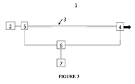
- Figure 3 shows a schematic drawing of a system (1), according to the present invention, in which (2) represents a means of applying pressure to the solution, (3) represents a line from which the solution is injected, (4) represents a dosing unit, (5) represents a pressure-wave detection means, (6) represents a means of establishing the time difference t p - to and (7) represents a processing means.
- the processing means may be implemented in dedicated hardware (e.g., ASIC), configurable hardware (e.g., FPGA), programmable components (e.g., a DSP or general purpose processor with appropriate software), or any combination thereof.
- ASIC application-specific integrated circuit
- FPGA field-programmable gate array
- programmable components e.g., a DSP or general purpose processor with appropriate software
- the same component(s) may also include other functions, and may for example form part of a vehicle's ECU.
- said system further comprises a means of calculating said concentration of a chemical agent in solution from the velocity of wave propagation of said pressure wave.
- Means for pressurizing a solution include rotary and piston pumps.
- said means of pressurizing comprises a rotary pump.
- the means of exactly establishing the time at which the valve opens may be a pressure sensor, the control signal changing the opening condition of the injector or an injector current pattern indicative of the injector opening.
- said means for detecting a change in pressure is a pressure sensor.
- any pressure sensor otherwise known as pressure transducers, pressure transmitters, pressure senders, pressure indicators and piezometers, known to persons skilled in the art may be used.
- Types include piezoresistive in which strain gauges using bonded or formed strain gauges are used to detect strain due to applied pressure, resistance increasing as pressure deforms the material; capacitive using a diaphragm and pressure cavity to create a variable capacitor to detect strain due to applied pressure, capacitance decreasing as pressure deforms the diaphragm; electromagnetic which measure the displacement of a diaphragm by means of changes in inductance (reluctance), LVDT, Hall Effect, or by eddy current principle; piezoelectric using the piezoelectric effect in certain materials such as quartz to measure the strain upon the sensing mechanism due to pressure.
- the means for pressurizing said solution comprises a pump driven by an electrical current
- said means for detecting a change in pressure (5) comprises a current sensor arranged on said pump.
- said line comprises a material having a Young's modulus of at least 69 GPa.
- said line comprises a material having a Young's modulus of at least 100 GPa.
- said line comprises a material having a Young's modulus of at least 200 GPa.
- said line comprises a material selected from the group consisting of aluminium, aramid, bronze, brass, titanium, copper, steel, molybdenum and graphene.
- said line comprises a material selected from the group consisting of steel, molybdenum and graphene.
- said chemical agent is urea as an aqueous solution.
- said chemical agent is ammonia as an aqueous solution.
- said system further comprises a means of maintaining the temperature of said chemical agent solution at a predetermined temperature.
- a temperature sensor is present in said line.
Landscapes
- Chemical & Material Sciences (AREA)
- Physics & Mathematics (AREA)
- Engineering & Computer Science (AREA)
- Health & Medical Sciences (AREA)
- Immunology (AREA)
- General Physics & Mathematics (AREA)
- Pathology (AREA)
- General Health & Medical Sciences (AREA)
- Biochemistry (AREA)
- Acoustics & Sound (AREA)
- Life Sciences & Earth Sciences (AREA)
- Analytical Chemistry (AREA)
- Chemical Kinetics & Catalysis (AREA)
- General Engineering & Computer Science (AREA)
- Combustion & Propulsion (AREA)
- Mechanical Engineering (AREA)
- Toxicology (AREA)
- Exhaust Gas After Treatment (AREA)
- Infusion, Injection, And Reservoir Apparatuses (AREA)
- Exhaust Gas Treatment By Means Of Catalyst (AREA)
Abstract
Description
- The present invention relates to a method of determining the concentration of a chemical agent in a solution and a system therefor.
- Legislation on vehicle and truck emissions stipulates, amongst other things, a reduction in the release of nitrogen oxides NOx into the atmosphere. One known way to achieve this objective is to use the SCR (Selective Catalytic Reduction) process which enables the reduction of nitrogen oxides by injection of a reducing agent, generally ammonia, into the exhaust line.
- SCR operation is improved by using chemical agents which are transported and/or stored on vehicles, marine facilities and industrial facilities. For example, "AdBlue" and "DEF" are trade names for a chemical agent corresponding substantially to aqueous urea solution 32.5%. This solution is injected into exhaust gases of modern diesel engines during a post-combustion process for treating engine exhaust gases for reducing a proportion of harmful nitrous oxide (NOx) present in these gases. AdBlue, DEF, "Adblu" is only ever used in conjunction with an SCR. Moreover, vehicles which are equipped with an SCR will carry an AdBlue, DEF or "Adblu" storage tank in addition to a fuel tank. In operation, AdBlue, DEF, or "Adblu" is transferred from the storage tank and injected under pressure into exhaust gases where a series of chemical reactions occur.
- An important factor in the injection of solutions of such chemical agents into exhaust gases is the concentration of that chemical agent in the solution. Since this concentration is crucial to the efficiency of the SCR process, multiple detection methods are typically required as a check to ensure that the system is operating as required, also to check the plausibility of the data from other detection methods.
-
DE 19850799A1 discloses a sensor arrangement for detecting physical parameters of fluids, with electroacoustic converters, which generate and detect acoustic surface waves with given wave modes, a measure for physical properties of fluids, in particular, amongst other things the viscosity of the fluids being detectable from its propagation behaviour along a propagation path, characterised in that the sensor arrangement is located on a substrate on which conductor track structures of such a type are arranged, that alongside the viscosity, the temperature and also at least the dielectric constants of the fluid can be detected. It is a disadvantage of this system, that acoustic surface waves must be actively generated in order to measure the properties of the fluid. - There is a need for compact and efficient systems for correctly detecting the concentration of the chemical agent in the injection system, so as so to improve control of the amount of agent to be injected.
- It is an object of the present invention to provide a system for correctly detecting the concentration of the chemical agent in the injection system, so as to improve control of the amount of agent to be injected, in particular under the form of a plausibility check on the reading of an existing concentration sensor.
- Surprisingly the precision with which propagation times can be measured enables the propagation speed of pressure waves in a hydraulic line to be used to estimate the concentration of a solution of a chemical agent, a variation of ca. 1 ms in a transit time of ca. 30 ms being observed for a variation in concentration of an aqueous solution of urea between 10% and 40% by weight..
- The propagation-speed of pressure waves (and accoustics) in a hydraulic line depends on the dimensions of the line, upon the Young modulus of the line material and of the ratio bulk modulus/density of the liquid in the line. In a typical SCR application, there is a pump to provide the pressure (typically 5 bar) in the line, an injector to spray the liquid in the exhaust pipe and a hydraulic line connecting both. This hydraulic line has a certain length. At the instance the injector is opened (closed), the pressure decreases (increases) locally. This pressure variation is given in the case of the line being a pipe by the expression:

where c is the speed of pressure propagation of the acoustic wave travelling backwards in the line material as a result of the opening of the valve, B is the bulk modulus of the liquid, ρ is the density of the liquid, D is the external diameter of the pipe, e is the thickness of the pipe and E is the Young's modulus of the pipe material. This expression reflects propagation through the line by two mechanisms: (i) the propagation of the deformation of the line, which will depend on the diameter, the wall thickness and the Young's modulus of the line, which parameters are in principle known; and (ii) the local compression and expansion of the liquid, which is detemined by two properties: the density and the Bulk modulus. Mechanism (ii) is the dominant mechanism if (DB)/(eE) « 1. Then determination of the speed of this pressure wave propagation (or the time for this propagation, since the length of the line is known) enables the determination of the Bulk modulus divided by the density according to the approximated equation:
If mechanism (ii) is not the dominant mechanism this equation does not hold and corrections have to be made. This is in part a function of the diameter and wall-thickness of the pipe, but is mainly determined by the Young's modulus of the wall material. - It is clear from the above that the approximated equation can be rendered applicable by a judicious choice of the material of the pipe, viz. by choosing a pipe material with a high Young's modules, such as steel (E = 200 GPa).
- The impact of the Young's modulus can be obtained by comparing the estimated wave propagation speed of different liquids through steel and PVC piping: the wave propagation speed in glycerol with a bulk modulus of 4.5 GPa is 1890 m/s which is reduced to 1400 m/s in steel piping (E = 200 GPa) and 380 m/s in PVC piping (E = 2.4 - 4.1 GPa); whereas the propagation speed in water with a bulk modulus of 2.2 GPa is 1480 m/s which is reduced to 1100 m/s in steel piping and 300 m/s in PVC piping. These data show that the ability of this method of determining the concentration of a chemical agent to distinguish concentration differences will increase with increasing Young's modulus of the pipe materials with maximum differentiation when the criterion (DB)/(eE) << 1 is fulfilled. However, the accuracy with which the concentration of a chemical agent in a solution needs to be determined is much lower for plausibility purposes (i.e., for checking the plausibility of a value obtained by using another sensor, whether an incorrect measurement or a defective sensor) than for other purposes.
- According to a first aspect of the present invention, a method of determining the concentration of a chemical agent in a solution is provided, the method comprising the steps of: providing a pressurized solution of said chemical agent upstream of a dosing unit, for example an injection valve, in a line; changing the opening condition of said dosing unit at a determinable time to to provide a dosing of said solution or a change in the dosing of said solution; determining the time, tp, at which the pressure wave in said line resulting from the pressure drop (due to release of pressure) upon changing the opening condition of said dosing unit is detected at a known distance, d, from said dosing unit; determining the velocity of wave propagation from said time interval tp - to and said known distance, d; and deriving the concentration of said chemical agent from said velocity of wave propagation.
- The term "upstream" is used with reference to the normal direction of flow of the fluid when the dosing unit (injector) is active; hence, a position "upstream of a dosing unit" refers to the non-injecting side of the dosing unit. The term "pressurized" refers to the fact that the pressure of the fluid upstream of the dosing unit is sufficiently high to cause fluid to flow into and through the dosing unit when the dosing unit is opened; in a particular embodiment, the fluid may be pressurized up to 3 bar, preferably even up to 5 bar.
- In an embodiment, the line comprises a material having a Young's modulus of at least 69 GPa, preferably at least 100 GPa, most preferably at least 200 GPa.
- In an embodiment, the concentration of said chemical agent is derived with the assistance of look-up tables or polynomials.
- According to a second aspect of the present invention a system is provided for determining the concentration of a chemical agent in a solution, said system comprising a means of pressurizing said solution, a line arranged between said means of applying pressure and an dosing unit having different opening conditions, means for detecting a change in pressure at a known distance from said dosing unit, a means of establishing a time difference between a time at which the opening condition of said dosing unit changes and a time at which the pressure wave in said solution resulting therefrom is detected by said means for detecting a change in pressure, and a processing means configured to derive the concentration of said chemical agent from said time difference.
- In an embodiment, the means for detecting a change in pressure comprises a pressure sensor such as for example a piezo-electric transducer (e.g., a piezoresistive sensor or a piezoelectric sensor), a capacitive sensor, or an electromagnetic sensor. In another embodiment, the means for pressurizing said solution comprises a pump driven by an electrical current, and said means for detecting a change in pressure comprises a current sensor arranged on said pump.
- According to a third aspect of the present invention, the use is provided of the second aspect of the present invention for checking the plausibility of the concentration of the chemical agent in the solution determined by another sensor present in the system.
- According to a fourth aspect of the present invention a vehicular selective catalytic reduction assembly is provided, said assembly comprising the system of the second aspect of the present invention.
- According to a fifth aspect of the present invention, a motor vehicle is provided comprising the system of the second aspect of the present invention.
- Particular and preferred aspects of the invention are set out in the accompanying independent and dependent claims. Features from the dependent claims may be combined with features of the independent claims and with features of other dependent claims as appropriate and not merely as explicitly set out in the claims.
- Although there has been constant improvement, change and evolution of devices in this field, the present concepts are believed to represent substantial new and novel improvements, including departures from prior practices, resulting in the provision of more efficient, stable and reliable devices of this nature.
- The above and other characteristics, features and advantages of the present invention will become apparent from the following detailed description, taken in conjunction with the accompanying drawings, which illustrate, by way of example, the principles of the invention. This description is given for the sake of example only, without limiting the scope of the invention. The reference figures quoted below refer to the attached drawings.
-
-
Figure 1 shows a simulated plot of pressure against time for an initial pressure of 5 bar for urea concentrations varying between 10 and 40% by weight and the injector side (lower set of curves) and at the pump side (upper set of curves). -
Figure 2 shows a magnified part ofFigure 1 between 99.124 and 99.130 s in which curves A, B, C and D are the characteristics for aqueous solutions with 10% by weight, 20% by weight, 30% by weight and 40% by weight of urea respectively. -
Figure 3 illustrates schematically a system for determining the concentration of a chemical agent in a solution, according to a particular embodiment of the present invention. - In the different figures, the same reference signs refer to the same or analogous elements.
- The term "opening condition", as used in disclosing the present invention, means fully open and any definable condition between fully open and completely shut.
- The term "line", as used in disclosing the present invention, means any means capable of transporting a solution and includes entities with a circular, elliptical, rectangular or square cross-section.
- The invention will now be described by a detailed description of several embodiments of the invention. It is clear that other embodiments of the invention can be configured according to the knowledge of persons skilled in the art without departing from the true spirit or technical teaching of the invention, the invention being limited only by the terms of the appended claims.
- It is to be understood that although preferred embodiments, specific constructions and configurations, as well as materials, have been discussed herein for devices according to the present invention, various changes or modifications in form and detail may be made without departing from the scope and spirit of this invention. Steps may be added or deleted to methods described within the scope of the present invention.
- While the invention is described hereinafter with reference to an SCR system, it is not limited thereto. In the following description, the reference to urea solutions is exemplary, and not intended to be limiting. The skilled person will appreciate that certain SCR systems operate with ammonia solutions, the concentration of which may also be determined by using embodiments of the present invention.
- According to a first aspect of the present invention, a method of determining the concentration of a chemical agent in a solution is provided, the method comprising the steps of: providing a pressurized solution of said chemical agent upstream of a dosing unit in a line; changing the opening condition of said dosing unit at a determinable time to to provide a dosing of said solution or a change in the dosing of said solution; determining the time, tp, at which the pressure wave in said line resulting from the pressure drop upon changing the opening condition of said dosing unit is detected, for example by a pressure sensor, at a known distance, d, from said valve; determining the velocity of wave propagation from said time interval tp - to and said known distance, d; and deriving the concentration of said chemical agent from said velocity of wave propagation.
- According to a preferred embodiment of the first aspect of the present invention, the means of exactly establishing the time at which the valve opens may be a pressure sensor, the control signal changing the opening condition of the injector or an injector current pattern indicative of the injector opening.
- According to another preferred embodiment of the first aspect of the present invention, the pressure drop is detected by means of a pressure sensor in said line.
- According to another preferred embodiment of the first aspect of the present invention, is the pressure drop is detected by reference to the motor current information of said pump.
- According to another preferred embodiment of the first aspect of the present invention, said chemical agent is urea.
- According to another preferred embodiment of the first aspect of the present invention, said solution is an aqueous urea solution.
- According to another preferred embodiment of the first aspect of the present invention, said chemical agent is ammonia.
- According to another preferred embodiment of the first aspect of the present invention, said solution is an aqueous ammonia solution.
- According to another preferred embodiment of the first aspect of the present invention, said line comprises a material having a Young's modulus of at least 69 GPa.
- According to another preferred embodiment of the first aspect of the present invention, said line comprises a material having a Young's modulus of at least 100 GPa.
- According to another preferred embodiment of the first aspect of the present invention, said line comprises a material having a Young's modulus of at least 200 GPa.
- According to another preferred embodiment of the first aspect of the present invention, said method further comprises the step of injecting said solution of said chemical agent into an exhaust line of a vehicle.
- According to another preferred embodiment of the first aspect of the present invention, said line comprises a material selected from the group consisting of aluminium, aramid, bronze, brass, titanium, copper, steel, molybdenum and graphene.
- According to another preferred embodiment of the first aspect of the present invention, said line comprises a material selected from the group consisting of aramid, bronze, brass, titanium, copper, steel, molybdenum and graphene.
- According to another preferred embodiment of the first aspect of the present invention, said line comprises a material selected from the group consisting of steel, molybdenum and graphene.
- According to another preferred embodiment of the first aspect of the present invention, said chemical agent is urea as an aqueous solution.
- According to another preferred embodiment of the first aspect of the present invention, when said solution of said chemical agent is maintained at a predetermined temperature.
- According to another preferred embodiment of the first aspect of the present invention, said method further comprises the step of measuring the temperature of said chemical agent solution and the thereby measured temperature is taken into account in calculating said concentration of said chemical agent in said solution with the assistance of look-up tables.
Figure 1 shows a simulated plot of pressure against time for an initial pressure of 5 bar applied by a rotary pump for urea concentrations varying between 10 and 40% by weight and the injector side (lower set of curves) and at the pump side (upper set of curves) and
Figure 2 shows a magnified part ofFigure 1 between 99.124 and 99.130 s in which curves A, B, C and D are the characteristics for aqueous solutions with 10% by weight, 20% by weight, 30% by weight and 40% by weight of urea respectively at the pump side of the injector. - The set of curves at the pump side exhibits a ca. 1 ms spread in a total wave propagation time of ca. 30.7 ms between concentrations of 10 and 40% by weight.
- The arrival time window of 1 ms is fairly small i.e. the spread in propagation wave arrival times for urea concentrations between 10 and 40% by weight, but in terms of the propagation time of about 30.7 ms is about 3% thereof, which taking the accuracy of time determination into account is accurately measureable. What is also clear from the ripple on these simulated plots is the presence of sinusoidal noise resulting from the action of the rotary pump.
- Noise can arise from different sources: from the pump applying the pressure, from imperfections in the piping walls, generated by the injection process and from the system. These are definable and hence can be filtered out.
- According to a second aspect of the present invention a system (1) is provided for determining the concentration of a chemical agent in a solution, said system (1) comprising a means of pressurizing said solution (2), a line (3) arranged between said means of applying pressure (2) and a dosing unit having different opening conditions (4), a means for detecting a change in pressure (5) at a known distance from said dosing unit (4), a means of establishing a time difference (6) between a time at which the opening condition of said dosing unit (4), changes and the time at which the pressure wave in said solution resulting therefrom is detected by said means for detecting a change in pressure (5), and a processing means (7) configured to derive the concentration of said chemical agent from said time difference.
-
Figure 3 shows a schematic drawing of a system (1), according to the present invention, in which (2) represents a means of applying pressure to the solution, (3) represents a line from which the solution is injected, (4) represents a dosing unit, (5) represents a pressure-wave detection means, (6) represents a means of establishing the time difference tp - to and (7) represents a processing means. - The processing means may be implemented in dedicated hardware (e.g., ASIC), configurable hardware (e.g., FPGA), programmable components (e.g., a DSP or general purpose processor with appropriate software), or any combination thereof. The same component(s) may also include other functions, and may for example form part of a vehicle's ECU.
- According to a preferred embodiment of the second aspect of the present invention, said system further comprises a means of calculating said concentration of a chemical agent in solution from the velocity of wave propagation of said pressure wave.
- Means for pressurizing a solution include rotary and piston pumps. According to a preferred embodiment of the second aspect of the present invention, said means of pressurizing comprises a rotary pump.
- The means of exactly establishing the time at which the valve opens may be a pressure sensor, the control signal changing the opening condition of the injector or an injector current pattern indicative of the injector opening.
- According to another preferred embodiment of the second aspect of the present invention, said means for detecting a change in pressure is a pressure sensor.
- Any pressure sensor, otherwise known as pressure transducers, pressure transmitters, pressure senders, pressure indicators and piezometers, known to persons skilled in the art may be used. Types include piezoresistive in which strain gauges using bonded or formed strain gauges are used to detect strain due to applied pressure, resistance increasing as pressure deforms the material; capacitive using a diaphragm and pressure cavity to create a variable capacitor to detect strain due to applied pressure, capacitance decreasing as pressure deforms the diaphragm; electromagnetic which measure the displacement of a diaphragm by means of changes in inductance (reluctance), LVDT, Hall Effect, or by eddy current principle; piezoelectric using the piezoelectric effect in certain materials such as quartz to measure the strain upon the sensing mechanism due to pressure.
- According to another preferred embodiment of the second aspect of the present invention, the means for pressurizing said solution comprises a pump driven by an electrical current, and said means for detecting a change in pressure (5) comprises a current sensor arranged on said pump.
- According to another preferred embodiment of the second aspect of the present invention, said line comprises a material having a Young's modulus of at least 69 GPa.
- According to another preferred embodiment of the second aspect of the present invention, said line comprises a material having a Young's modulus of at least 100 GPa.
- According to another preferred embodiment of the second aspect of the present invention, said line comprises a material having a Young's modulus of at least 200 GPa.
- According to another preferred embodiment of the second aspect of the present invention, said line comprises a material selected from the group consisting of aluminium, aramid, bronze, brass, titanium, copper, steel, molybdenum and graphene.
- According to another preferred embodiment of the second aspect of the present invention, said line comprises a material selected from the group consisting of steel, molybdenum and graphene.
- According to another preferred embodiment of the second aspect of the present invention, said chemical agent is urea as an aqueous solution.
- According to another preferred embodiment of the second aspect of the present invention, said chemical agent is ammonia as an aqueous solution.
- According to another preferred embodiment of the second aspect of the present invention, said system further comprises a means of maintaining the temperature of said chemical agent solution at a predetermined temperature.
- According to another preferred embodiment of the second aspect of the present invention, a temperature sensor is present in said line.
- While the invention has been described hereinabove with reference to specific embodiments, this was done to clarify and not to limit the invention. The skilled person will appreciate that various modifications and different combinations of disclosed features are possible without departing from the scope of the invention. In particular, details that have only been described with reference to the method embodiments may be applied mutatis mutandis to the system embodiments with the same technical effects, and vice versa.
Claims (12)
- A method of determining the concentration of a chemical agent in a solution the method comprising the steps of:providing a pressurized solution of said chemical agent upstream of a dosing unit in a line;changing the opening condition of said dosing unit at a determinable time to to provide a dosing of said solution or a change in the dosing of said solution;determining the time, tp, at which the pressure wave in said line resulting from the pressure drop upon changing the opening condition of said dosing unit is detected in said line at a known distance, d, from said dosing unit;determining the velocity of wave propagation from said time interval tp - to and said known distance, d; andderiving the concentration of said chemical agent from said velocity of wave propagation.
- The method according to claim 1, wherein the means of exactly establishing the time at which the valve opens may be a pressure sensor, the control signal changing the opening condition of the injector or an injector current pattern indicative of the injector opening.
- The method according to claim 1 or 2, wherein said chemical agent is urea.
- The method according to claim 3, wherein said solution is an aqueous urea solution.
- The method according to any of the preceding claims, further comprising the step of injecting said solution of said chemical agent into an exhaust line of a vehicle.
- A system (1) for determining the concentration of a chemical agent in a solution, said system comprising a means of pressurizing said solution (2), a line (3) arranged between said means of applying pressure (2) and a dosing unit having different opening conditions (4), means for detecting a change in pressure (5) at a known distance from said dosing unit (4), a means of establishing a time difference (6) between a time at which the opening condition of said dosing unit (4) changes and a time at which the pressure wave in said solution resulting therefrom is detected by said means for detecting a change in pressure (5), and processing means (7) configured to derive the concentration of said chemical agent from said time difference.
- The system (1) according to claim 6, wherein the means for detecting a change in pressure (5) comprises a pressure sensor.
- The system (1) according to claim 6, wherein the means for pressurizing said solution comprises a pump driven by an electrical current, and wherein said means for detecting a change in pressure (5) comprises a current sensor arranged on said pump.
- The system according to any one of claims 6 to 8, wherein said means of applying a pressure comprises a rotary pump.
- The use of a system according to any one of claims 6 to 9 for checking the plausibility of said concentration of said chemical agent in said solution determined by another sensor.
- A vehicular selective catalytic reduction assembly comprising a system according to any one of claims 6 to 9.
- A motor vehicle comprising a system according to any one of claims 6 to 9.
Priority Applications (8)
| Application Number | Priority Date | Filing Date | Title |
|---|---|---|---|
| EP15189624.8A EP3156620B1 (en) | 2015-10-13 | 2015-10-13 | Method of determining the concentration of a chemical agent in a solution based on a pressure wave velocity and a system therefor |
| EP16781451.6A EP3362655A1 (en) | 2015-10-13 | 2016-10-13 | Method of determining one physicochemical parameter of a chemical agent in a fluid and a system therefor |
| CN201680059647.9A CN108138628A (en) | 2015-10-13 | 2016-10-13 | Method and system for determining a physicochemical parameter of a chemical agent in a fluid |
| US15/767,792 US20180306754A1 (en) | 2015-10-13 | 2016-10-13 | Method of determining one physicochemical parameter of a chemical agent in a fluid and a system therefor |
| PCT/EP2016/074623 WO2017064204A1 (en) | 2015-10-13 | 2016-10-13 | Method of determining one physicochemical parameter of a chemical agent in a fluid and a system therefor |
| KR1020187012350A KR20180064447A (en) | 2015-10-13 | 2016-10-13 | Method for determining one physico-chemical parameter of a chemical agent in fluid and system therefor |
| BR112018007287A BR112018007287A2 (en) | 2015-10-13 | 2016-10-13 | method of determining a physicochemical parameter of a chemical agent in a fluid and a system for the same |
| JP2018519023A JP2019501367A (en) | 2015-10-13 | 2016-10-13 | Method and system for determining one physicochemical parameter of a chemical substance in a fluid |
Applications Claiming Priority (1)
| Application Number | Priority Date | Filing Date | Title |
|---|---|---|---|
| EP15189624.8A EP3156620B1 (en) | 2015-10-13 | 2015-10-13 | Method of determining the concentration of a chemical agent in a solution based on a pressure wave velocity and a system therefor |
Publications (2)
| Publication Number | Publication Date |
|---|---|
| EP3156620A1 true EP3156620A1 (en) | 2017-04-19 |
| EP3156620B1 EP3156620B1 (en) | 2018-09-12 |
Family
ID=54325406
Family Applications (2)
| Application Number | Title | Priority Date | Filing Date |
|---|---|---|---|
| EP15189624.8A Not-in-force EP3156620B1 (en) | 2015-10-13 | 2015-10-13 | Method of determining the concentration of a chemical agent in a solution based on a pressure wave velocity and a system therefor |
| EP16781451.6A Withdrawn EP3362655A1 (en) | 2015-10-13 | 2016-10-13 | Method of determining one physicochemical parameter of a chemical agent in a fluid and a system therefor |
Family Applications After (1)
| Application Number | Title | Priority Date | Filing Date |
|---|---|---|---|
| EP16781451.6A Withdrawn EP3362655A1 (en) | 2015-10-13 | 2016-10-13 | Method of determining one physicochemical parameter of a chemical agent in a fluid and a system therefor |
Country Status (7)
| Country | Link |
|---|---|
| US (1) | US20180306754A1 (en) |
| EP (2) | EP3156620B1 (en) |
| JP (1) | JP2019501367A (en) |
| KR (1) | KR20180064447A (en) |
| CN (1) | CN108138628A (en) |
| BR (1) | BR112018007287A2 (en) |
| WO (1) | WO2017064204A1 (en) |
Cited By (1)
| Publication number | Priority date | Publication date | Assignee | Title |
|---|---|---|---|---|
| GB2584476A (en) * | 2019-06-05 | 2020-12-09 | Delphi Tech Ip Ltd | A method of diagnosing a diesel exhaust fluid delivery system |
Families Citing this family (1)
| Publication number | Priority date | Publication date | Assignee | Title |
|---|---|---|---|---|
| CN116593579B (en) * | 2023-07-13 | 2023-11-03 | 湖北工业大学 | Method for estimating concentration of urea solution for vehicle |
Citations (3)
| Publication number | Priority date | Publication date | Assignee | Title |
|---|---|---|---|---|
| DE19850799A1 (en) | 1998-11-04 | 2000-05-11 | Bosch Gmbh Robert | Sensor arrangement for determining physical properties of liquids |
| EP1283332A2 (en) * | 2001-08-09 | 2003-02-12 | Robert Bosch Gmbh | Exhaust treatment unit and measuring device for determining the concentration of a urea and water solution |
| EP2826972A1 (en) * | 2013-07-15 | 2015-01-21 | Inergy Automotive Systems Research (Société Anonyme) | Method for monitoring urea quality of an SCR system |
Family Cites Families (6)
| Publication number | Priority date | Publication date | Assignee | Title |
|---|---|---|---|---|
| JP5533235B2 (en) * | 2010-05-17 | 2014-06-25 | いすゞ自動車株式会社 | NOx sensor diagnostic device and SCR system |
| FR2974903B1 (en) * | 2011-05-05 | 2014-08-29 | Continental Automotive France | DEVICE FOR MEASURING CHARACTERISTICS IN A UREA RESERVOIR |
| DE102011103272B4 (en) * | 2011-05-26 | 2014-05-22 | Continental Automotive Gmbh | Method and apparatus for operating an SCR system |
| CN102518496A (en) * | 2012-01-05 | 2012-06-27 | 潍柴动力股份有限公司 | Method and system for controlling urea injecting quantity |
| DE102012200917B4 (en) * | 2012-01-23 | 2023-06-29 | Robert Bosch Gmbh | Method for detecting clogging of a dosing valve of an SCR catalytic converter system |
| DE102013218897A1 (en) * | 2013-09-20 | 2015-03-26 | Robert Bosch Gmbh | Method for monitoring the quantity of a metering or injection system of an internal combustion engine, in particular of a motor vehicle |
-
2015
- 2015-10-13 EP EP15189624.8A patent/EP3156620B1/en not_active Not-in-force
-
2016
- 2016-10-13 WO PCT/EP2016/074623 patent/WO2017064204A1/en not_active Ceased
- 2016-10-13 JP JP2018519023A patent/JP2019501367A/en active Pending
- 2016-10-13 US US15/767,792 patent/US20180306754A1/en not_active Abandoned
- 2016-10-13 KR KR1020187012350A patent/KR20180064447A/en not_active Withdrawn
- 2016-10-13 EP EP16781451.6A patent/EP3362655A1/en not_active Withdrawn
- 2016-10-13 CN CN201680059647.9A patent/CN108138628A/en active Pending
- 2016-10-13 BR BR112018007287A patent/BR112018007287A2/en not_active Application Discontinuation
Patent Citations (3)
| Publication number | Priority date | Publication date | Assignee | Title |
|---|---|---|---|---|
| DE19850799A1 (en) | 1998-11-04 | 2000-05-11 | Bosch Gmbh Robert | Sensor arrangement for determining physical properties of liquids |
| EP1283332A2 (en) * | 2001-08-09 | 2003-02-12 | Robert Bosch Gmbh | Exhaust treatment unit and measuring device for determining the concentration of a urea and water solution |
| EP2826972A1 (en) * | 2013-07-15 | 2015-01-21 | Inergy Automotive Systems Research (Société Anonyme) | Method for monitoring urea quality of an SCR system |
Cited By (3)
| Publication number | Priority date | Publication date | Assignee | Title |
|---|---|---|---|---|
| GB2584476A (en) * | 2019-06-05 | 2020-12-09 | Delphi Tech Ip Ltd | A method of diagnosing a diesel exhaust fluid delivery system |
| WO2020245428A1 (en) * | 2019-06-05 | 2020-12-10 | Delphi Technologies Ip Limited | A method of diagnosing a diesel exhaust fluid delivery system |
| GB2584476B (en) * | 2019-06-05 | 2022-03-23 | Delphi Tech Ip Ltd | A method of diagnosing a diesel exhaust fluid delivery system |
Also Published As
| Publication number | Publication date |
|---|---|
| EP3362655A1 (en) | 2018-08-22 |
| WO2017064204A1 (en) | 2017-04-20 |
| JP2019501367A (en) | 2019-01-17 |
| CN108138628A (en) | 2018-06-08 |
| US20180306754A1 (en) | 2018-10-25 |
| EP3156620B1 (en) | 2018-09-12 |
| BR112018007287A2 (en) | 2018-10-23 |
| KR20180064447A (en) | 2018-06-14 |
Similar Documents
| Publication | Publication Date | Title |
|---|---|---|
| KR102230828B1 (en) | Method and apparatus for monitoring tank contents of storage tank of exhaust gas treatment system | |
| CN102713603B (en) | Quality sensor equipment | |
| US10287959B2 (en) | Method for determining the aging of an oxidation catalyst in an exhaust gas aftertreatment system of an internal combustion engine, method for detecting ash in a particle filter of an exhaust gas aftertreatment system, control device, and internal combustion engine | |
| EP2960484B1 (en) | System for detecting an air filter condition, in particular for combustion engines | |
| CN101929394B (en) | Fuel state sensing device | |
| US20090205418A1 (en) | Procedure for controlling a digital fuel level sensor | |
| CN105229285B (en) | upstream NOx estimation | |
| CN110195635B (en) | Method for monitoring an ammonia slip catalyst | |
| US11203960B2 (en) | Method and device for determining the injection quantity or the injection rate of a fluid injected into a reaction space by means of an injector | |
| EP3156620B1 (en) | Method of determining the concentration of a chemical agent in a solution based on a pressure wave velocity and a system therefor | |
| CN103547919A (en) | Method and device for operating an SCR system | |
| US12259291B2 (en) | Method and device for determining an amplitude of a pump-induced fluid pressure fluctuation of a fluid | |
| US9389112B2 (en) | Method and device for detecting the tank filling level in a motor vehicle | |
| US10995749B2 (en) | Method for monitoring the volumetric flow of a metering valve of a fluidic metering system of an internal combustion engine, in particular of a motor vehicle | |
| KR20140036319A (en) | Method and device for testing a liquid | |
| DE102012217891A1 (en) | Method for determining fill level of fuel in fuel tank mounted in motor vehicle, involves determining fill level of tank from propagation time of ultrasonic signal and inclination angle of tank based on intensities of ultrasonic signal | |
| EP3557017B1 (en) | Exhaust gas aftertreatment system for diesel engine and method of detecting abnormal injection | |
| CN113008979B (en) | Method for determining the concentration of a liquid | |
| US11808196B2 (en) | Method of detecting a need for regeneration of an exhaust particulate filter, and exhaust system | |
| Ning et al. | Detection of injected urea quantity and correction for SCR urea dosing control | |
| CN102954924B (en) | For determining equipment and the method for the quality of reductant solution | |
| Dekate et al. | Calibration and Optimization of OBD Strategies for Selective Catalytic Reduction Systems for BSVI Application | |
| CN110953051A (en) | Method for the quality detection of a reducing agent | |
| CN109838289A (en) | The pumpback process monitoring system and method for aqueous solution of urea spraying system |
Legal Events
| Date | Code | Title | Description |
|---|---|---|---|
| PUAI | Public reference made under article 153(3) epc to a published international application that has entered the european phase |
Free format text: ORIGINAL CODE: 0009012 |
|
| AK | Designated contracting states |
Kind code of ref document: A1 Designated state(s): AL AT BE BG CH CY CZ DE DK EE ES FI FR GB GR HR HU IE IS IT LI LT LU LV MC MK MT NL NO PL PT RO RS SE SI SK SM TR |
|
| AX | Request for extension of the european patent |
Extension state: BA ME |
|
| 17P | Request for examination filed |
Effective date: 20170906 |
|
| RBV | Designated contracting states (corrected) |
Designated state(s): AL AT BE BG CH CY CZ DE DK EE ES FI FR GB GR HR HU IE IS IT LI LT LU LV MC MK MT NL NO PL PT RO RS SE SI SK SM TR |
|
| REG | Reference to a national code |
Ref country code: DE Ref legal event code: R079 Ref document number: 602015016009 Country of ref document: DE Free format text: PREVIOUS MAIN CLASS: F01N0003200000 Ipc: G01N0029024000 |
|
| RIC1 | Information provided on ipc code assigned before grant |
Ipc: F01N 11/00 20060101ALI20180126BHEP Ipc: G01N 29/024 20060101AFI20180126BHEP Ipc: F01N 3/20 20060101ALI20180126BHEP Ipc: G01N 29/22 20060101ALI20180126BHEP |
|
| GRAP | Despatch of communication of intention to grant a patent |
Free format text: ORIGINAL CODE: EPIDOSNIGR1 |
|
| RAP1 | Party data changed (applicant data changed or rights of an application transferred) |
Owner name: PLASTIC OMNIUM ADVANCED INNOVATION AND RESEARCH |
|
| INTG | Intention to grant announced |
Effective date: 20180319 |
|
| GRAS | Grant fee paid |
Free format text: ORIGINAL CODE: EPIDOSNIGR3 |
|
| GRAA | (expected) grant |
Free format text: ORIGINAL CODE: 0009210 |
|
| AK | Designated contracting states |
Kind code of ref document: B1 Designated state(s): AL AT BE BG CH CY CZ DE DK EE ES FI FR GB GR HR HU IE IS IT LI LT LU LV MC MK MT NL NO PL PT RO RS SE SI SK SM TR |
|
| REG | Reference to a national code |
Ref country code: GB Ref legal event code: FG4D |
|
| REG | Reference to a national code |
Ref country code: CH Ref legal event code: EP |
|
| REG | Reference to a national code |
Ref country code: IE Ref legal event code: FG4D |
|
| REG | Reference to a national code |
Ref country code: DE Ref legal event code: R096 Ref document number: 602015016009 Country of ref document: DE |
|
| REG | Reference to a national code |
Ref country code: AT Ref legal event code: REF Ref document number: 1041212 Country of ref document: AT Kind code of ref document: T Effective date: 20181015 |
|
| REG | Reference to a national code |
Ref country code: FR Ref legal event code: PLFP Year of fee payment: 4 |
|
| REG | Reference to a national code |
Ref country code: NL Ref legal event code: MP Effective date: 20180912 |
|
| REG | Reference to a national code |
Ref country code: LT Ref legal event code: MG4D |
|
| PG25 | Lapsed in a contracting state [announced via postgrant information from national office to epo] |
Ref country code: NO Free format text: LAPSE BECAUSE OF FAILURE TO SUBMIT A TRANSLATION OF THE DESCRIPTION OR TO PAY THE FEE WITHIN THE PRESCRIBED TIME-LIMIT Effective date: 20181212 Ref country code: GR Free format text: LAPSE BECAUSE OF FAILURE TO SUBMIT A TRANSLATION OF THE DESCRIPTION OR TO PAY THE FEE WITHIN THE PRESCRIBED TIME-LIMIT Effective date: 20181213 Ref country code: SE Free format text: LAPSE BECAUSE OF FAILURE TO SUBMIT A TRANSLATION OF THE DESCRIPTION OR TO PAY THE FEE WITHIN THE PRESCRIBED TIME-LIMIT Effective date: 20180912 Ref country code: BG Free format text: LAPSE BECAUSE OF FAILURE TO SUBMIT A TRANSLATION OF THE DESCRIPTION OR TO PAY THE FEE WITHIN THE PRESCRIBED TIME-LIMIT Effective date: 20181212 Ref country code: LT Free format text: LAPSE BECAUSE OF FAILURE TO SUBMIT A TRANSLATION OF THE DESCRIPTION OR TO PAY THE FEE WITHIN THE PRESCRIBED TIME-LIMIT Effective date: 20180912 Ref country code: FI Free format text: LAPSE BECAUSE OF FAILURE TO SUBMIT A TRANSLATION OF THE DESCRIPTION OR TO PAY THE FEE WITHIN THE PRESCRIBED TIME-LIMIT Effective date: 20180912 Ref country code: RS Free format text: LAPSE BECAUSE OF FAILURE TO SUBMIT A TRANSLATION OF THE DESCRIPTION OR TO PAY THE FEE WITHIN THE PRESCRIBED TIME-LIMIT Effective date: 20180912 |
|
| PG25 | Lapsed in a contracting state [announced via postgrant information from national office to epo] |
Ref country code: AL Free format text: LAPSE BECAUSE OF FAILURE TO SUBMIT A TRANSLATION OF THE DESCRIPTION OR TO PAY THE FEE WITHIN THE PRESCRIBED TIME-LIMIT Effective date: 20180912 Ref country code: LV Free format text: LAPSE BECAUSE OF FAILURE TO SUBMIT A TRANSLATION OF THE DESCRIPTION OR TO PAY THE FEE WITHIN THE PRESCRIBED TIME-LIMIT Effective date: 20180912 Ref country code: HR Free format text: LAPSE BECAUSE OF FAILURE TO SUBMIT A TRANSLATION OF THE DESCRIPTION OR TO PAY THE FEE WITHIN THE PRESCRIBED TIME-LIMIT Effective date: 20180912 |
|
| REG | Reference to a national code |
Ref country code: AT Ref legal event code: MK05 Ref document number: 1041212 Country of ref document: AT Kind code of ref document: T Effective date: 20180912 |
|
| PG25 | Lapsed in a contracting state [announced via postgrant information from national office to epo] |
Ref country code: AT Free format text: LAPSE BECAUSE OF FAILURE TO SUBMIT A TRANSLATION OF THE DESCRIPTION OR TO PAY THE FEE WITHIN THE PRESCRIBED TIME-LIMIT Effective date: 20180912 Ref country code: NL Free format text: LAPSE BECAUSE OF FAILURE TO SUBMIT A TRANSLATION OF THE DESCRIPTION OR TO PAY THE FEE WITHIN THE PRESCRIBED TIME-LIMIT Effective date: 20180912 Ref country code: RO Free format text: LAPSE BECAUSE OF FAILURE TO SUBMIT A TRANSLATION OF THE DESCRIPTION OR TO PAY THE FEE WITHIN THE PRESCRIBED TIME-LIMIT Effective date: 20180912 Ref country code: IT Free format text: LAPSE BECAUSE OF FAILURE TO SUBMIT A TRANSLATION OF THE DESCRIPTION OR TO PAY THE FEE WITHIN THE PRESCRIBED TIME-LIMIT Effective date: 20180912 Ref country code: EE Free format text: LAPSE BECAUSE OF FAILURE TO SUBMIT A TRANSLATION OF THE DESCRIPTION OR TO PAY THE FEE WITHIN THE PRESCRIBED TIME-LIMIT Effective date: 20180912 Ref country code: ES Free format text: LAPSE BECAUSE OF FAILURE TO SUBMIT A TRANSLATION OF THE DESCRIPTION OR TO PAY THE FEE WITHIN THE PRESCRIBED TIME-LIMIT Effective date: 20180912 Ref country code: CZ Free format text: LAPSE BECAUSE OF FAILURE TO SUBMIT A TRANSLATION OF THE DESCRIPTION OR TO PAY THE FEE WITHIN THE PRESCRIBED TIME-LIMIT Effective date: 20180912 Ref country code: PL Free format text: LAPSE BECAUSE OF FAILURE TO SUBMIT A TRANSLATION OF THE DESCRIPTION OR TO PAY THE FEE WITHIN THE PRESCRIBED TIME-LIMIT Effective date: 20180912 Ref country code: IS Free format text: LAPSE BECAUSE OF FAILURE TO SUBMIT A TRANSLATION OF THE DESCRIPTION OR TO PAY THE FEE WITHIN THE PRESCRIBED TIME-LIMIT Effective date: 20190112 |
|
| PG25 | Lapsed in a contracting state [announced via postgrant information from national office to epo] |
Ref country code: SK Free format text: LAPSE BECAUSE OF FAILURE TO SUBMIT A TRANSLATION OF THE DESCRIPTION OR TO PAY THE FEE WITHIN THE PRESCRIBED TIME-LIMIT Effective date: 20180912 Ref country code: PT Free format text: LAPSE BECAUSE OF FAILURE TO SUBMIT A TRANSLATION OF THE DESCRIPTION OR TO PAY THE FEE WITHIN THE PRESCRIBED TIME-LIMIT Effective date: 20190112 Ref country code: SM Free format text: LAPSE BECAUSE OF FAILURE TO SUBMIT A TRANSLATION OF THE DESCRIPTION OR TO PAY THE FEE WITHIN THE PRESCRIBED TIME-LIMIT Effective date: 20180912 |
|
| REG | Reference to a national code |
Ref country code: CH Ref legal event code: PL |
|
| REG | Reference to a national code |
Ref country code: DE Ref legal event code: R097 Ref document number: 602015016009 Country of ref document: DE |
|
| REG | Reference to a national code |
Ref country code: BE Ref legal event code: MM Effective date: 20181031 |
|
| PG25 | Lapsed in a contracting state [announced via postgrant information from national office to epo] |
Ref country code: LU Free format text: LAPSE BECAUSE OF NON-PAYMENT OF DUE FEES Effective date: 20181013 |
|
| PLBE | No opposition filed within time limit |
Free format text: ORIGINAL CODE: 0009261 |
|
| STAA | Information on the status of an ep patent application or granted ep patent |
Free format text: STATUS: NO OPPOSITION FILED WITHIN TIME LIMIT |
|
| REG | Reference to a national code |
Ref country code: IE Ref legal event code: MM4A |
|
| PG25 | Lapsed in a contracting state [announced via postgrant information from national office to epo] |
Ref country code: MC Free format text: LAPSE BECAUSE OF FAILURE TO SUBMIT A TRANSLATION OF THE DESCRIPTION OR TO PAY THE FEE WITHIN THE PRESCRIBED TIME-LIMIT Effective date: 20180912 Ref country code: DK Free format text: LAPSE BECAUSE OF FAILURE TO SUBMIT A TRANSLATION OF THE DESCRIPTION OR TO PAY THE FEE WITHIN THE PRESCRIBED TIME-LIMIT Effective date: 20180912 |
|
| 26N | No opposition filed |
Effective date: 20190613 |
|
| PG25 | Lapsed in a contracting state [announced via postgrant information from national office to epo] |
Ref country code: CH Free format text: LAPSE BECAUSE OF NON-PAYMENT OF DUE FEES Effective date: 20181031 Ref country code: BE Free format text: LAPSE BECAUSE OF NON-PAYMENT OF DUE FEES Effective date: 20181031 Ref country code: SI Free format text: LAPSE BECAUSE OF FAILURE TO SUBMIT A TRANSLATION OF THE DESCRIPTION OR TO PAY THE FEE WITHIN THE PRESCRIBED TIME-LIMIT Effective date: 20180912 Ref country code: LI Free format text: LAPSE BECAUSE OF NON-PAYMENT OF DUE FEES Effective date: 20181031 |
|
| PG25 | Lapsed in a contracting state [announced via postgrant information from national office to epo] |
Ref country code: IE Free format text: LAPSE BECAUSE OF NON-PAYMENT OF DUE FEES Effective date: 20181013 |
|
| PG25 | Lapsed in a contracting state [announced via postgrant information from national office to epo] |
Ref country code: MT Free format text: LAPSE BECAUSE OF NON-PAYMENT OF DUE FEES Effective date: 20181013 |
|
| PG25 | Lapsed in a contracting state [announced via postgrant information from national office to epo] |
Ref country code: TR Free format text: LAPSE BECAUSE OF FAILURE TO SUBMIT A TRANSLATION OF THE DESCRIPTION OR TO PAY THE FEE WITHIN THE PRESCRIBED TIME-LIMIT Effective date: 20180912 |
|
| PG25 | Lapsed in a contracting state [announced via postgrant information from national office to epo] |
Ref country code: HU Free format text: LAPSE BECAUSE OF FAILURE TO SUBMIT A TRANSLATION OF THE DESCRIPTION OR TO PAY THE FEE WITHIN THE PRESCRIBED TIME-LIMIT; INVALID AB INITIO Effective date: 20151013 Ref country code: MK Free format text: LAPSE BECAUSE OF NON-PAYMENT OF DUE FEES Effective date: 20180912 Ref country code: CY Free format text: LAPSE BECAUSE OF FAILURE TO SUBMIT A TRANSLATION OF THE DESCRIPTION OR TO PAY THE FEE WITHIN THE PRESCRIBED TIME-LIMIT Effective date: 20180912 |
|
| GBPC | Gb: european patent ceased through non-payment of renewal fee |
Effective date: 20191013 |
|
| PG25 | Lapsed in a contracting state [announced via postgrant information from national office to epo] |
Ref country code: GB Free format text: LAPSE BECAUSE OF NON-PAYMENT OF DUE FEES Effective date: 20191013 |
|
| PGFP | Annual fee paid to national office [announced via postgrant information from national office to epo] |
Ref country code: FR Payment date: 20201030 Year of fee payment: 6 |
|
| PG25 | Lapsed in a contracting state [announced via postgrant information from national office to epo] |
Ref country code: FR Free format text: LAPSE BECAUSE OF NON-PAYMENT OF DUE FEES Effective date: 20211031 |
|
| P01 | Opt-out of the competence of the unified patent court (upc) registered |
Effective date: 20230515 |
|
| PGFP | Annual fee paid to national office [announced via postgrant information from national office to epo] |
Ref country code: DE Payment date: 20231020 Year of fee payment: 9 |
|
| REG | Reference to a national code |
Ref country code: DE Ref legal event code: R119 Ref document number: 602015016009 Country of ref document: DE |
|
| PG25 | Lapsed in a contracting state [announced via postgrant information from national office to epo] |
Ref country code: DE Free format text: LAPSE BECAUSE OF NON-PAYMENT OF DUE FEES Effective date: 20250501 |