EP3156613A2 - Blade outer air seal - Google Patents
Blade outer air seal Download PDFInfo
- Publication number
- EP3156613A2 EP3156613A2 EP16192466.7A EP16192466A EP3156613A2 EP 3156613 A2 EP3156613 A2 EP 3156613A2 EP 16192466 A EP16192466 A EP 16192466A EP 3156613 A2 EP3156613 A2 EP 3156613A2
- Authority
- EP
- European Patent Office
- Prior art keywords
- leading edge
- cooling passage
- aft
- main body
- outer air
- Prior art date
- Legal status (The legal status is an assumption and is not a legal conclusion. Google has not performed a legal analysis and makes no representation as to the accuracy of the status listed.)
- Granted
Links
Images


Classifications
-
- F—MECHANICAL ENGINEERING; LIGHTING; HEATING; WEAPONS; BLASTING
- F01—MACHINES OR ENGINES IN GENERAL; ENGINE PLANTS IN GENERAL; STEAM ENGINES
- F01D—NON-POSITIVE DISPLACEMENT MACHINES OR ENGINES, e.g. STEAM TURBINES
- F01D11/00—Preventing or minimising internal leakage of working-fluid, e.g. between stages
- F01D11/08—Preventing or minimising internal leakage of working-fluid, e.g. between stages for sealing space between rotor blade tips and stator
-
- F—MECHANICAL ENGINEERING; LIGHTING; HEATING; WEAPONS; BLASTING
- F01—MACHINES OR ENGINES IN GENERAL; ENGINE PLANTS IN GENERAL; STEAM ENGINES
- F01D—NON-POSITIVE DISPLACEMENT MACHINES OR ENGINES, e.g. STEAM TURBINES
- F01D11/00—Preventing or minimising internal leakage of working-fluid, e.g. between stages
- F01D11/02—Preventing or minimising internal leakage of working-fluid, e.g. between stages by non-contact sealings, e.g. of labyrinth type
-
- F—MECHANICAL ENGINEERING; LIGHTING; HEATING; WEAPONS; BLASTING
- F01—MACHINES OR ENGINES IN GENERAL; ENGINE PLANTS IN GENERAL; STEAM ENGINES
- F01D—NON-POSITIVE DISPLACEMENT MACHINES OR ENGINES, e.g. STEAM TURBINES
- F01D25/00—Component parts, details, or accessories, not provided for in, or of interest apart from, other groups
- F01D25/08—Cooling; Heating; Heat-insulation
- F01D25/12—Cooling
-
- F—MECHANICAL ENGINEERING; LIGHTING; HEATING; WEAPONS; BLASTING
- F16—ENGINEERING ELEMENTS AND UNITS; GENERAL MEASURES FOR PRODUCING AND MAINTAINING EFFECTIVE FUNCTIONING OF MACHINES OR INSTALLATIONS; THERMAL INSULATION IN GENERAL
- F16J—PISTONS; CYLINDERS; SEALINGS
- F16J15/00—Sealings
- F16J15/44—Free-space packings
-
- F—MECHANICAL ENGINEERING; LIGHTING; HEATING; WEAPONS; BLASTING
- F05—INDEXING SCHEMES RELATING TO ENGINES OR PUMPS IN VARIOUS SUBCLASSES OF CLASSES F01-F04
- F05D—INDEXING SCHEME FOR ASPECTS RELATING TO NON-POSITIVE-DISPLACEMENT MACHINES OR ENGINES, GAS-TURBINES OR JET-PROPULSION PLANTS
- F05D2220/00—Application
- F05D2220/30—Application in turbines
- F05D2220/32—Application in turbines in gas turbines
-
- F—MECHANICAL ENGINEERING; LIGHTING; HEATING; WEAPONS; BLASTING
- F05—INDEXING SCHEMES RELATING TO ENGINES OR PUMPS IN VARIOUS SUBCLASSES OF CLASSES F01-F04
- F05D—INDEXING SCHEME FOR ASPECTS RELATING TO NON-POSITIVE-DISPLACEMENT MACHINES OR ENGINES, GAS-TURBINES OR JET-PROPULSION PLANTS
- F05D2240/00—Components
- F05D2240/10—Stators
- F05D2240/11—Shroud seal segments
-
- F—MECHANICAL ENGINEERING; LIGHTING; HEATING; WEAPONS; BLASTING
- F05—INDEXING SCHEMES RELATING TO ENGINES OR PUMPS IN VARIOUS SUBCLASSES OF CLASSES F01-F04
- F05D—INDEXING SCHEME FOR ASPECTS RELATING TO NON-POSITIVE-DISPLACEMENT MACHINES OR ENGINES, GAS-TURBINES OR JET-PROPULSION PLANTS
- F05D2240/00—Components
- F05D2240/55—Seals
-
- F—MECHANICAL ENGINEERING; LIGHTING; HEATING; WEAPONS; BLASTING
- F05—INDEXING SCHEMES RELATING TO ENGINES OR PUMPS IN VARIOUS SUBCLASSES OF CLASSES F01-F04
- F05D—INDEXING SCHEME FOR ASPECTS RELATING TO NON-POSITIVE-DISPLACEMENT MACHINES OR ENGINES, GAS-TURBINES OR JET-PROPULSION PLANTS
- F05D2250/00—Geometry
- F05D2250/30—Arrangement of components
- F05D2250/31—Arrangement of components according to the direction of their main axis or their axis of rotation
- F05D2250/314—Arrangement of components according to the direction of their main axis or their axis of rotation the axes being inclined in relation to each other
-
- F—MECHANICAL ENGINEERING; LIGHTING; HEATING; WEAPONS; BLASTING
- F05—INDEXING SCHEMES RELATING TO ENGINES OR PUMPS IN VARIOUS SUBCLASSES OF CLASSES F01-F04
- F05D—INDEXING SCHEME FOR ASPECTS RELATING TO NON-POSITIVE-DISPLACEMENT MACHINES OR ENGINES, GAS-TURBINES OR JET-PROPULSION PLANTS
- F05D2260/00—Function
- F05D2260/20—Heat transfer, e.g. cooling
-
- Y—GENERAL TAGGING OF NEW TECHNOLOGICAL DEVELOPMENTS; GENERAL TAGGING OF CROSS-SECTIONAL TECHNOLOGIES SPANNING OVER SEVERAL SECTIONS OF THE IPC; TECHNICAL SUBJECTS COVERED BY FORMER USPC CROSS-REFERENCE ART COLLECTIONS [XRACs] AND DIGESTS
- Y02—TECHNOLOGIES OR APPLICATIONS FOR MITIGATION OR ADAPTATION AGAINST CLIMATE CHANGE
- Y02T—CLIMATE CHANGE MITIGATION TECHNOLOGIES RELATED TO TRANSPORTATION
- Y02T50/00—Aeronautics or air transport
- Y02T50/60—Efficient propulsion technologies, e.g. for aircraft
Definitions
- gas turbine engines and other turbomachines, include multiple sections, such as a fan section, a compressor section, a combustor section, a turbine section, and an exhaust section.
- Air moves into the engine through the fan section.
- Airfoil arrays in the compressor section rotate to compress the air, which is then mixed with fuel and combusted in the combustor section.
- the products of combustion are expanded to rotatably drive airfoil arrays in the turbine section. Rotating the airfoil arrays in the turbine section drives rotation of the fan and compressor sections.
- a blade outer air seal arrangement includes multiple blade outer air seals (BOAS) circumferentially disposed about at least a portion of the airfoil arrays.
- BOAS blade outer air seals
- a blade outer air seal assembly comprising: a main body portion that extends generally axially, with respect to a central axis, from a leading edge portion of the main body portion to a trailing edge portion of the main body portion, wherein the leading edge portion includes a leading edge wall having a undercut profile, along at least a portion of the leading edge wall; at least one attachment portion coupled to the main body portion, the at least one attachment portion configured for attachment to a receiving portion of the turbine, the at least one attachment portion comprising at least one leading attachment portion proximate the leading edge portion; and cooling passages defined within the main body portion, comprising a leading edge cooling passage adjacent to the leading edge wall, and at least one aft cooling passage axially aligned aft of the leading edge cooling passage, wherein the leading edge cooling passage has a leading edge periphery on a side of the leading edge cooling passage adjacent to the leading edge wall, wherein the leading edge periphery runs substantially parallel to the undercut profile of
- leading edge periphery is configured to substantially maintain a distance between the leading edge wall and the leading edge cooling passage of between 0.05 cm and 0.2 cm. In one embodiment, the leading edge periphery is configured to substantially maintain a constant distance between the leading edge wall and the leading edge cooling passage.
- the blade outer air seal assembly comprises a plurality of axially aligned aft cooling passages comprising top linear edges and bottom linear edges, wherein the top linear edges define a ceiling line of the plurality of aft cooling passages, and the bottom linear edges define a floor line of the plurality of aft cooling passages, wherein the leading edge cooling passage has at least a bottom edge which deviates from the floor line of the plurality of aft cooling passages.
- the aft cooling passages comprise an elongated geometry comprising at least one of a discorectangle rounded rectangle, or rectangle.
- the leading edge cooling passage comprises at least one of a tilted, undercut, or bent configuration with respect to the aft cooling passages. In one embodiment, the leading edge cooling passage is tilted with respect to the at least one aft cooling passage. In one embodiment, the leading edge cooling passage is bent with respect to the at least one aft cooling passage. In one embodiment, the leading edge cooling passage is undercut with respect to the at least one aft cooling passage. In one embodiment, the leading edge cooling passage is undercut and at least one of tilted or bent with respect to the at least one aft cooling passage.
- a blade outer air seal assembly for a turbine engine comprising: a main body portion that extends generally axially, with respect to a central axis of the turbine engine, from a leading edge portion of the main body portion to a trailing edge portion of the main body portion, wherein the leading edge portion includes a leading edge wall having a undercut profile, along at least a portion of the leading edge wall; and cooling passages defined within the main body portion, comprising a leading edge cooling passage adjacent to the leading edge wall, and at least one aft cooling passage axially aligned aft of the leading edge cooling passage, wherein the at least one aft cooling passage comprises a top linear edge define a ceiling line, and a bottom linear edge define a floor line, wherein the leading edge cooling passage deviates from the axial alignment of the at least one aft cooling passage, wherein the leading edge cooling passage has a leading edge periphery on a side of the leading edge cooling passage adjacent to the leading edge wall
- the leading edge periphery is configured to substantially maintain a distance between the leading edge wall and the leading edge cooling passage of between 60mm and 120mm. In one embodiment, the leading edge periphery is configured to substantially maintain a constant distance between the leading edge wall and the leading edge cooling passage.
- the blade outer air seal assembly comprises a plurality of axially aligned aft cooling passages, comprising top linear edges defining the ceiling line, and bottom linear edges defining the floor line, wherein the aft cooling passages comprise an elongated geometry comprising at least one of a discorectangle rounded rectangle, or rectangle.
- the leading edge cooling passage comprises at least one of a tilted, undercut, or bent configuration with respect to the at least one aft cooling passage. In one embodiment, the leading edge cooling passage projects above the ceiling line. In one embodiment, the leading edge cooling passage is undercut and at least one of tilted or bent with respect to the at least one aft cooling passage.
- a turbine engine comprising a blade outer air seal assembly
- the blade outer air seal assembly comprising: a main body portion that extends generally axially, with respect to a central axis of the turbine engine, from a leading edge portion of the main body portion to a trailing edge portion of the main body portion, wherein the leading edge portion includes a leading edge wall having a undercut profile, along at least a portion of the leading edge wall; and at least one cooling passage defined within the main body portion and adjacent to the leading edge wall, the at least one cooling passage having a leading edge periphery on a side adjacent to the leading edge wall which runs substantially parallel to the undercut profile of the leading edge wall, and maintains a generally constant distance between the leading edge periphery and the leading edge wall.
- the turbine engine further comprises a plurality of axially aligned aft cooling passages, comprising top linear edges defining a ceiling line, and bottom linear edges defining a floor line, wherein the aft cooling passages comprise an elongated geometry comprising at least one of a discorectangle rounded rectangle, or rectangle, wherein the at least one cooling passage having a leading edge periphery deviates from the axial alignment of the aft cooling passages, and comprises at least one of a tilted, undercut, or bent configuration with respect to the aft cooling passages.
- gas turbine engine 20 may be a two-spool turbofan that generally incorporates a fan section 22, a compressor section 24, a combustor section 26 and a turbine section 28, for example.
- Alternative engines might include an augmentor section (not shown) among other systems or features, according to various embodiments.
- the fan section 22 drives air along a bypass flowpath while the compressor section 24 drives air along a core flowpath for compression and communication into the combustor section 26 then expansion through the turbine section 28.
- turbofan gas turbine engine in the disclosed non-limiting embodiment, it should be understood that the concepts described herein are not limited to use with turbofans as the teachings may be applied to other types of turbine engines including three-spool architectures, non-geared turbine engines, and land-based turbines, according to various embodiments.
- gas turbine engine 20 may generally include a first spool 30 and a second spool 32 mounted for rotation about an engine central axis A relative to an engine static structure 36 via several bearing systems 38. It should be understood that various bearing systems 38 at various locations may alternatively or additionally be provided, according to various embodiments.
- the first spool 30 may generally include a first shaft 40 that interconnects a fan 42, a first compressor 43 and a first turbine 46.
- the first shaft 40 may be connected to the fan 42 through a gear assembly of a fan drive gear system 48 to drive the fan 42 at a lower speed than the first spool 30.
- the second spool 32 may include a second shaft 49 that interconnects a second compressor 52 and second turbine 55.
- the first spool 30 may run at a relatively lower pressure than the second spool 32. It is to be understood that "low pressure” and “high pressure” or variations thereof as used herein are relative terms indicating that the high pressure is greater than the low pressure.
- an annular combustor 57 may be arranged between the second compressor 52 and the second turbine 55.
- the first shaft 40 and the second shaft 49 may be concentric and rotate via bearing systems 38 about the engine central axis A which is collinear with their longitudinal axes, according to various embodiments.
- the core airflow may be compressed by the first compressor 43 then the second compressor 52, mixed and burned with fuel in the annular combustor 57, then expanded over the second turbine 55 and first turbine 46.
- the first turbine 46 and the second turbine 55 may rotationally drive, respectively, the first spool 30 and the second spool 32 in response to the expansion.
- gas turbine engine 20 may be a high-bypass geared aircraft engine that has a bypass ratio that is greater than about six (6), with an example embodiment being greater than ten (10).
- the gear assembly of the fan drive gear system 48 may be an epicyclic gear train, such as a planetary gear system or other gear system, with a gear reduction ratio of greater than about 2.3:1 and the first turbine 46 may have a pressure ratio that is greater than about 5, for example.
- the first turbine 46 pressure ratio is pressure measured prior to inlet of first turbine 46 as related to the pressure at the outlet of the first turbine 46 prior to an exhaust nozzle.
- first turbine 46 may have a maximum rotor diameter and the fan 42 may have a fan diameter such that a ratio of the maximum rotor diameter divided by the fan diameter is less than 0.6. It should be understood, however, that the above parameters are only exemplary.
- the fan section 22 of the gas turbine engine 20 may be designed for a particular flight condition-typically cruise at an airspeed of 0.8 Mach and altitude of 35,000 feet (10.67 km).
- fuel consumption is reduced to a common metric which is applicable to all types and sizes of turbojets and turbofans.
- the term that may be used to compare fuel consumption between engines is thrust specific fuel consumption, or TSFC. This is an engine's fuel consumption in pounds per hour divided by the net thrust.
- TSFC is the amount of fuel required to produce one pound of thrust.
- the TSFC unit is pounds per hour per pounds of thrust (lb/hr/lb Fn).
- SFC specific fuel consumption
- Low fan pressure ratio is the pressure ratio across the fan blade alone, without a fan exit guide Vane system.
- the low fan pressure ratio as disclosed herein according to one non-limiting embodiment is less than about 1.45.
- the "Low corrected fan tip speed” as disclosed herein according to one non-limiting embodiment may be less than about 1150 feet per second (350 m/s).
- FIG. 2 shows a blade outer air seal (BOAS) assembly 50 attached to an inner engine case structure 44 of the gas turbine engine 20 by a receiving portion 68 of the inner engine case structure 44.
- the BOAS assembly 50 may be located within the turbine section 28 of the gas turbine engine 20, for example.
- the BOAS assembly 50 faces turbine blade 51 to define a radial tip clearance 53 between the turbine blade 51 and the BOAS assembly 50.
- a number of BOAS assembly 50 may be arranged circumferentially about engine axis A to form a shroud, according to various embodiments.
- the BOAS assemblies 50 may alternatively be formed as a unitary BOAS structure, with the same features described herein.
- the BOAS assembly 50 may include a main body portion 54 that extends generally axially from a leading edge portion 56 to a trailing edge portion 58 and from a radially outward facing surface 62 at an outboard side of BOAS assembly 50 to a radially inward facing surface 64 at an inboard side of BOAS assembly 50.
- the BOAS assembly 50 also includes at least one leading attachment portion 60a (also referred to as "attachment portions 60a”) disposed at or near the leading edge portion 56 and at least one trailing attachment portion 60b (also referred to as "attachment portions 60b”) disposed at or near the trailing edge portion 58.
- each of the attachment portions 60a, 60b may define a flange 66.
- flange 66 of attachment portions 60a and/or 60b may extend in an axially aft direction, as shown in the figures.
- flange 66 of attachment portions 60a and/or 60b may alternatively extend in an axially fore direction.
- each axially extending flange 66 corresponds to the receiving portion 68 of the inner engine case structure 44 to support and attach the BOAS assembly 50 (Shown in FIG. 2 ).
- the attachment portions 60a may be circumferentially offset, circumferentially aligned, or a combination of both, from the attachment portions 60b in response to BOAS assembly 50 parameters.
- the leading edge portion 56 of BOAS assembly 50 includes a leading edge wall 56a having an undercut profile 56b, along at least a portion of the leading edge wall 56a, as shown in Figures 3A-D , and indicated by broken lines in Figure 2 .
- the undercut profile 56b which may have various configurations, deviates away from a 90 degree geometry 56c (indicated by broken lines in Figure 2 ).
- undercut profile 56b may include a beveled or chamfered profile (e.g. 30 degree chamfer, 45 degree chamfer, etc.), a radial or elliptical transition.
- the undercut profile 56b of leading edge wall 56a may improve gas flow transition across leading edge wall 56a, and to prevent a stagnation region at the leading edge portion 56.
- the BOAS assembly 50 further comprises cooling passages 86 defined within the main body portion 54.
- cooling passages 86 include a leading edge cooling passage 86a adjacent to the leading edge wall 56a, and aft cooling passages 86b axially aligned aft of the leading edge cooling passage 86a.
- aft cooling passages 86b each comprise an elongated geometry with a bottom linear edge 121 and a top linear edge 123, wherein bottom linear edges 121 generally defining a floor line 122 of the aft cooling passages 86b, and top linear edges 123, generally defining a ceiling line 124 of the aft cooling passages 86b.
- the elongated geometry of aft cooling passages 86b comprises rounded ends, and may include a discorectangle or stadium geometry, or rounded rectangle, according to various embodiments. Other similar geometries may include a rectangle geometry, according to various embodiments.
- leading edge cooling passage 86a has a leading edge periphery 87 (also referred to as "conforming periphery 87) which generally conforms to the undercut profile 56b of the leading edge wall 56a, on the side adjacent to the leading edge wall 56a.
- the conforming periphery 87 is configured to substantially maintain a distance between the leading edge wall 56a and leading edge cooling passage 86a, of between 60mm and 120mm, thus creating a desirable wall thickness between the leading edge wall 56a and leading edge cooling passage 86a, which would otherwise be compromised if the leading edge cooling passage 86a were to conform with the geometry and alignment of the aft cooling passages 86b.
- a distance d1 (with brief reference back to FIG. 2 ), between a portion of the leading edge wall 56a having the 90 degree geometry 56c may be shortened to a distance d2 at a portion of the leading edge wall 56a having the undercut profile 56b, as shown in Figure 2 . If d2 is too small, local wall thickness may decrease below a desirable a wall thickness. If d2 is too large, local wall thickness may exceed a desirable value. These are undesirable, as a reduced wall thickness may subject the BOAS assembly 50 to casting defects, while a high wall thickness may adversely affect the cooling efficiency of the BOAS assembly 50.
- a wall thickness may include a generally constant wall thickness between the leading edge periphery 87 and the leading edge wall 56a.
- leading edge cooling passage 86a may be tilted, undercut, and/or bent, in comparison to aft cooling passages 86b, such that the leading edge periphery 87 conforms to the undercut profile.
- leading edge cooling passage 86a may be tilted with respect to aft cooling passages 86b, as shown in Figure 3A , wherein its bottom linear edge 121 is angled with respect to floor line 122 formed by the aft cooling passages 86b.
- bottom linear edge 121 of leading edge cooling passage 86a runs substantially parallel to the undercut profile 56b of the leading edge wall 56a, forming the leading edge periphery 87.
- leading edge cooling passage 86a having a tilted configuration may have a geometric configuration similar to the elongated geometry of aft cooling passages 86b.
- leading edge cooling passage 86a having a tilted configuration may project above the ceiling line 124 formed by the top linear edge 123 of the aft cooling passages 86b.
- leading edge cooling passage 86a may be undercut with respect to aft cooling passages 86b, as shown in Figure 3B .
- leading edge cooling passage 86a may be coaxially aligned with aft cooling passages 86b, and diagonally undercut through its bottom linear edge 121, wherein the diagonal undercut is angled with respect to the floor line 122 formed by the aft cooling passages 86b.
- leading edge cooling passage 86a may be diagonally undercut through its bottom linear edge 121, wherein the diagonal undercut runs parallel or substantially parallel to the undercut profile 56b of the leading edge wall 56a, forming the leading edge periphery 87.
- leading edge cooling passage 86a having an undercut configuration may be confined within the ceiling line 124 and floor line 122 formed by the aft cooling passages 86b.
- the leading edge cooling passage 86a may be bent, with respect to aft cooling passages 86b, as shown in Figure 3C , such that only a portion of the leading edge cooling passage 86a is tilted.
- a segment of bottom linear edge 121 of leading edge cooling passage 86a is angled with respect to with respect to floor line 122 formed by the aft cooling passages 86b.
- leading edge cooling passage 86a having a bent configuration runs parallel or substantially parallel to the undercut profile 56b of the leading edge wall 56a, forming the leading edge periphery 87, while the remaining segment may be coaxially aligned with aft cooling passages 86b, as shown in the Figure.
- leading edge cooling passage 86a having a bent configuration may project above the ceiling line 124 formed by the top linear edge 123 of the aft cooling passages 86b.
- the leading edge cooling passage 86a may both tilted and undercut, as shown in Figure 3D , or both bent and undercut.
- bent or tilted cooling passage 86a may be undercut to eliminate its projection above ceiling line 124, such that it is confined within the ceiling line 124 and floor line 122 formed by the aft cooling passages 86b.
- bent or tilted cooling passage 86a may be undercut such that its projection above ceiling line 124 is reduced (as shown in Figure 3d , for a tilted configuration).
- the BOAS assembly 50 may be fabricated from a material such as an austenitic nickel-chromium-based alloy such as Inconel® which is available from Special Metals Corporation of New Hartford, New York, USA. According to various embodiments, the BOAS assembly 50 may be fabricated from such alloy having sulfur levels at or below 1 part per million (PPM), though other types of material may be used, according to various embodiments. According to various embodiments, a distance 118 between the floor line 122 of the plurality of cooling passages 86 and the radially inward facing surface 64 may be between 0.02 inches (0.05 cm) and 0.080 inches (0.2 cm). For example, the distance 118 may be about 0.027 inches (0.069 cm), according to various embodiments.
- an austenitic nickel-chromium-based alloy such as Inconel® which is available from Special Metals Corporation of New Hartford, New York, USA.
- the BOAS assembly 50 may be fabricated from such alloy having sulfur levels at or below 1 part per million (PPM), though other types of material may be used,
- the BOAS assembly 50 may include a thermal barrier coating (e.g., a metallic or based coating, multiple layers of coating such as a thermal layer and a bond layer, etc.) disposed on the radially inward facing surface 64 of the main body portion 54, according to various embodiments.
- a thermal barrier coating e.g., a metallic or based coating, multiple layers of coating such as a thermal layer and a bond layer, etc.
- the BOAS assembly 50 is subjected to different thermal loads and environmental conditions.
- the BOAS assembly 50 is in fluid communication with an airflow source, such as an upstream compressor in the compressor section 24 or other source, which provides cooling airflow, such as bleed compressor air. This provides varying levels of cooling to different areas of the BOAS assembly 50 and effectively communicate thermal energy away from the BOAS assembly 50 and the tip of the rotating turbine blade 51.
- references to "various embodiments”, “one embodiment”, “an embodiment”, “an example embodiment”, etc. indicate that the embodiment described may include a particular feature, structure, or characteristic, but every embodiment may not necessarily include the particular feature, structure, or characteristic. Moreover, such phrases are not necessarily referring to the same embodiment. Further, when a particular feature, structure, or characteristic is described in connection with an embodiment, it is submitted that it is within the knowledge of one skilled in the art to affect such feature, structure, or characteristic in connection with other embodiments whether or not explicitly described. After reading the description, it will be apparent to one skilled in the relevant art(s) how to implement the disclosure in alternative embodiments.
Landscapes
- Engineering & Computer Science (AREA)
- General Engineering & Computer Science (AREA)
- Mechanical Engineering (AREA)
- Turbine Rotor Nozzle Sealing (AREA)
- Structures Of Non-Positive Displacement Pumps (AREA)
Abstract
Description
- As known, gas turbine engines, and other turbomachines, include multiple sections, such as a fan section, a compressor section, a combustor section, a turbine section, and an exhaust section. Air moves into the engine through the fan section. Airfoil arrays in the compressor section rotate to compress the air, which is then mixed with fuel and combusted in the combustor section. The products of combustion are expanded to rotatably drive airfoil arrays in the turbine section. Rotating the airfoil arrays in the turbine section drives rotation of the fan and compressor sections.
- A blade outer air seal arrangement includes multiple blade outer air seals (BOAS) circumferentially disposed about at least a portion of the airfoil arrays. As known, the blade outer air seal environment is exposed to temperature extremes and other harsh environmental conditions, which may affect the integrity of the blade outer air seal. Thus, effective cooling is typically desired to protect the BOAS.
- In accordance with various embodiments, disclosed is a blade outer air seal assembly comprising: a main body portion that extends generally axially, with respect to a central axis, from a leading edge portion of the main body portion to a trailing edge portion of the main body portion, wherein the leading edge portion includes a leading edge wall having a undercut profile, along at least a portion of the leading edge wall; at least one attachment portion coupled to the main body portion, the at least one attachment portion configured for attachment to a receiving portion of the turbine, the at least one attachment portion comprising at least one leading attachment portion proximate the leading edge portion; and cooling passages defined within the main body portion, comprising a leading edge cooling passage adjacent to the leading edge wall, and at least one aft cooling passage axially aligned aft of the leading edge cooling passage, wherein the leading edge cooling passage has a leading edge periphery on a side of the leading edge cooling passage adjacent to the leading edge wall, wherein the leading edge periphery runs substantially parallel to the undercut profile of the leading edge wall. In one embodiment, the leading edge periphery is configured to substantially maintain a distance between the leading edge wall and the leading edge cooling passage of between 0.05 cm and 0.2 cm. In one embodiment, the leading edge periphery is configured to substantially maintain a constant distance between the leading edge wall and the leading edge cooling passage. In one embodiment, the blade outer air seal assembly comprises a plurality of axially aligned aft cooling passages comprising top linear edges and bottom linear edges, wherein the top linear edges define a ceiling line of the plurality of aft cooling passages, and the bottom linear edges define a floor line of the plurality of aft cooling passages, wherein the leading edge cooling passage has at least a bottom edge which deviates from the floor line of the plurality of aft cooling passages. In one embodiment, the aft cooling passages comprise an elongated geometry comprising at least one of a discorectangle rounded rectangle, or rectangle. In one embodiment, the leading edge cooling passage comprises at least one of a tilted, undercut, or bent configuration with respect to the aft cooling passages. In one embodiment, the leading edge cooling passage is tilted with respect to the at least one aft cooling passage. In one embodiment, the leading edge cooling passage is bent with respect to the at least one aft cooling passage. In one embodiment, the leading edge cooling passage is undercut with respect to the at least one aft cooling passage. In one embodiment, the leading edge cooling passage is undercut and at least one of tilted or bent with respect to the at least one aft cooling passage.
- In accordance with various embodiments, disclosed is a blade outer air seal assembly for a turbine engine comprising: a main body portion that extends generally axially, with respect to a central axis of the turbine engine, from a leading edge portion of the main body portion to a trailing edge portion of the main body portion, wherein the leading edge portion includes a leading edge wall having a undercut profile, along at least a portion of the leading edge wall; and cooling passages defined within the main body portion, comprising a leading edge cooling passage adjacent to the leading edge wall, and at least one aft cooling passage axially aligned aft of the leading edge cooling passage, wherein the at least one aft cooling passage comprises a top linear edge define a ceiling line, and a bottom linear edge define a floor line, wherein the leading edge cooling passage deviates from the axial alignment of the at least one aft cooling passage, wherein the leading edge cooling passage has a leading edge periphery on a side of the leading edge cooling passage adjacent to the leading edge wall, wherein the leading edge periphery generally conforms to the undercut profile of the leading edge wall. In one embodiment, the leading edge periphery is configured to substantially maintain a distance between the leading edge wall and the leading edge cooling passage of between 60mm and 120mm. In one embodiment, the leading edge periphery is configured to substantially maintain a constant distance between the leading edge wall and the leading edge cooling passage. In one embodiment, the blade outer air seal assembly comprises a plurality of axially aligned aft cooling passages, comprising top linear edges defining the ceiling line, and bottom linear edges defining the floor line, wherein the aft cooling passages comprise an elongated geometry comprising at least one of a discorectangle rounded rectangle, or rectangle. In one embodiment, the leading edge cooling passage comprises at least one of a tilted, undercut, or bent configuration with respect to the at least one aft cooling passage. In one embodiment, the leading edge cooling passage projects above the ceiling line. In one embodiment, the leading edge cooling passage is undercut and at least one of tilted or bent with respect to the at least one aft cooling passage.
- In accordance with various embodiments, disclosed is a turbine engine comprising a blade outer air seal assembly, the blade outer air seal assembly comprising: a main body portion that extends generally axially, with respect to a central axis of the turbine engine, from a leading edge portion of the main body portion to a trailing edge portion of the main body portion, wherein the leading edge portion includes a leading edge wall having a undercut profile, along at least a portion of the leading edge wall; and at least one cooling passage defined within the main body portion and adjacent to the leading edge wall, the at least one cooling passage having a leading edge periphery on a side adjacent to the leading edge wall which runs substantially parallel to the undercut profile of the leading edge wall, and maintains a generally constant distance between the leading edge periphery and the leading edge wall. In one embodiment, the generally constant distance is between 60mm and 120mm. In one embodiment, the turbine engine further comprises a plurality of axially aligned aft cooling passages, comprising top linear edges defining a ceiling line, and bottom linear edges defining a floor line, wherein the aft cooling passages comprise an elongated geometry comprising at least one of a discorectangle rounded rectangle, or rectangle, wherein the at least one cooling passage having a leading edge periphery deviates from the axial alignment of the aft cooling passages, and comprises at least one of a tilted, undercut, or bent configuration with respect to the aft cooling passages.
- The drawings described herein are for illustration purposes only and are not intended to limit the scope of the present disclosure in any way. The present disclosure will become more fully understood from the detailed description and the accompanying drawings wherein:
-
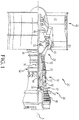
FIG. 1 shows a cross-section of gas turbine engine, according to various embodiments; -
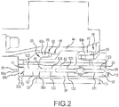
FIG. 2 shows a blade outer air seal (BOAS) assembly attached to an inner engine case structure of the gas turbine engine ofFIG. 1 , according to various embodiments; -
FIG. 3A shows a BOAS assembly having a tilted leading edge cooling passage, according to various embodiments; -
FIG. 3B shows a BOAS assembly having an undercut leading edge cooling passage, according to various embodiments; -
FIG. 3C shows a BOAS assembly having a bent leading edge cooling passage, according to various embodiments; and -
FIG. 3D shows a BOAS assembly having a tilted and undercut leading edge cooling passage, according to various embodiments. - All ranges and ratio limits disclosed herein may be combined. It is to be understood that unless specifically stated otherwise, references to "a," "an," and/or "the" may include one or more than one and that reference to an item in the singular may also include the item in the plural.
- The detailed description of exemplary embodiments herein makes reference to the accompanying drawings, which show exemplary embodiments by way of illustration and its best mode, and not of limitation. While these exemplary embodiments are described in sufficient detail to enable those skilled in the art to practice the invention, it should be understood that other embodiments may be realized and that logical, chemical and mechanical changes may be made without departing from the spirit and scope of the invention. For example, the steps recited in any of the method or process descriptions may be executed in any order and are not necessarily limited to the order presented. Moreover, many of the functions or steps may be outsourced to or performed by one or more third parties. Furthermore, any reference to singular includes plural embodiments, and any reference to more than one component or step may include a singular embodiment or step. Also, any reference to attached, fixed, connected or the like may include permanent, removable, temporary, partial, full and/or any other possible attachment option. Additionally, any reference to without contact (or similar phrases) may also include reduced contact or minimal contact.
- According to various embodiments, and with reference to
FIG. 1 , agas turbine engine 20 is schematically illustrated. According to various embodiments,gas turbine engine 20 may be a two-spool turbofan that generally incorporates afan section 22, acompressor section 24, acombustor section 26 and aturbine section 28, for example. Alternative engines might include an augmentor section (not shown) among other systems or features, according to various embodiments. According to various embodiments, thefan section 22 drives air along a bypass flowpath while thecompressor section 24 drives air along a core flowpath for compression and communication into thecombustor section 26 then expansion through theturbine section 28. Although depicted as a turbofan gas turbine engine in the disclosed non-limiting embodiment, it should be understood that the concepts described herein are not limited to use with turbofans as the teachings may be applied to other types of turbine engines including three-spool architectures, non-geared turbine engines, and land-based turbines, according to various embodiments. - According to various embodiments,
gas turbine engine 20 may generally include afirst spool 30 and asecond spool 32 mounted for rotation about an engine central axis A relative to an enginestatic structure 36 viaseveral bearing systems 38. It should be understood that various bearingsystems 38 at various locations may alternatively or additionally be provided, according to various embodiments. According to various embodiments, thefirst spool 30 may generally include afirst shaft 40 that interconnects afan 42, afirst compressor 43 and afirst turbine 46. According to various embodiments, thefirst shaft 40 may be connected to thefan 42 through a gear assembly of a fandrive gear system 48 to drive thefan 42 at a lower speed than thefirst spool 30. According to various embodiments, thesecond spool 32 may include asecond shaft 49 that interconnects asecond compressor 52 andsecond turbine 55. According to various embodiments, thefirst spool 30 may run at a relatively lower pressure than thesecond spool 32. It is to be understood that "low pressure" and "high pressure" or variations thereof as used herein are relative terms indicating that the high pressure is greater than the low pressure. According to various embodiments, anannular combustor 57 may be arranged between thesecond compressor 52 and thesecond turbine 55. According to various embodiments, thefirst shaft 40 and thesecond shaft 49 may be concentric and rotate via bearingsystems 38 about the engine central axis A which is collinear with their longitudinal axes, according to various embodiments. - According to various embodiments, the core airflow may be compressed by the
first compressor 43 then thesecond compressor 52, mixed and burned with fuel in theannular combustor 57, then expanded over thesecond turbine 55 andfirst turbine 46. According to various embodiments, thefirst turbine 46 and thesecond turbine 55 may rotationally drive, respectively, thefirst spool 30 and thesecond spool 32 in response to the expansion. According to various embodiments,gas turbine engine 20 may be a high-bypass geared aircraft engine that has a bypass ratio that is greater than about six (6), with an example embodiment being greater than ten (10). According to various embodiments, the gear assembly of the fandrive gear system 48 may be an epicyclic gear train, such as a planetary gear system or other gear system, with a gear reduction ratio of greater than about 2.3:1 and thefirst turbine 46 may have a pressure ratio that is greater than about 5, for example. According to various embodiments, thefirst turbine 46 pressure ratio is pressure measured prior to inlet offirst turbine 46 as related to the pressure at the outlet of thefirst turbine 46 prior to an exhaust nozzle. According to various embodiments,first turbine 46 may have a maximum rotor diameter and thefan 42 may have a fan diameter such that a ratio of the maximum rotor diameter divided by the fan diameter is less than 0.6. It should be understood, however, that the above parameters are only exemplary. - A significant amount of thrust may be provided by the bypass flow B due to the high bypass ratio. According to various embodiments, the
fan section 22 of thegas turbine engine 20 may be designed for a particular flight condition-typically cruise at an airspeed of 0.8 Mach and altitude of 35,000 feet (10.67 km). The flight condition of 0.8 Mach and 35,000 feet (10.67 km) engine operating at its best fuel consumption. To make an accurate comparison of fuel consumption between engines, fuel consumption is reduced to a common metric which is applicable to all types and sizes of turbojets and turbofans. The term that may be used to compare fuel consumption between engines is thrust specific fuel consumption, or TSFC. This is an engine's fuel consumption in pounds per hour divided by the net thrust. Stated another way, TSFC is the amount of fuel required to produce one pound of thrust. The TSFC unit is pounds per hour per pounds of thrust (lb/hr/lb Fn). When the reference is to a turbojet or turbofan engine, TSFC is often simply called specific fuel consumption, or SFC. "Low fan pressure ratio" is the pressure ratio across the fan blade alone, without a fan exit guide Vane system. The low fan pressure ratio as disclosed herein according to one non-limiting embodiment is less than about 1.45. "Low corrected fan tip speed" is the actual fan tip speed in feet per second divided by an industry standard temperature correction of [(Tram °R)/(518.7°R)]^0.5 (°R = K x 9/5). The "Low corrected fan tip speed" as disclosed herein according to one non-limiting embodiment may be less than about 1150 feet per second (350 m/s). - According to various embodiments,
FIG. 2 shows a blade outer air seal (BOAS)assembly 50 attached to an innerengine case structure 44 of thegas turbine engine 20 by a receivingportion 68 of the innerengine case structure 44. According to various embodiments, theBOAS assembly 50 may be located within theturbine section 28 of thegas turbine engine 20, for example. According to various embodiments, theBOAS assembly 50 facesturbine blade 51 to define aradial tip clearance 53 between theturbine blade 51 and theBOAS assembly 50. Although only oneBOAS assembly 50 is shown, a number ofBOAS assembly 50 may be arranged circumferentially about engine axis A to form a shroud, according to various embodiments. According to various embodiments, theBOAS assemblies 50 may alternatively be formed as a unitary BOAS structure, with the same features described herein. - According to various embodiments, and with reference to
FIGS. 2-3D , theBOAS assembly 50 may include a main body portion 54 that extends generally axially from aleading edge portion 56 to a trailingedge portion 58 and from a radially outward facingsurface 62 at an outboard side ofBOAS assembly 50 to a radially inward facingsurface 64 at an inboard side ofBOAS assembly 50. According to various embodiments, theBOAS assembly 50 also includes at least one leadingattachment portion 60a (also referred to as "attachment portions 60a") disposed at or near theleading edge portion 56 and at least one trailingattachment portion 60b (also referred to as "attachment portions 60b") disposed at or near the trailingedge portion 58. According to various embodiments, each of theattachment portions flange 66. According to various embodiments,flange 66 ofattachment portions 60a and/or 60b may extend in an axially aft direction, as shown in the figures. According to various embodiments,flange 66 ofattachment portions 60a and/or 60b may alternatively extend in an axially fore direction. - According to various embodiments, each axially extending
flange 66 corresponds to the receivingportion 68 of the innerengine case structure 44 to support and attach the BOAS assembly 50 (Shown inFIG. 2 ). According to various embodiments, theattachment portions 60a may be circumferentially offset, circumferentially aligned, or a combination of both, from theattachment portions 60b in response toBOAS assembly 50 parameters. - According to various embodiments, the leading
edge portion 56 ofBOAS assembly 50 includes aleading edge wall 56a having an undercutprofile 56b, along at least a portion of theleading edge wall 56a, as shown inFigures 3A-D , and indicated by broken lines inFigure 2 . The undercutprofile 56b, which may have various configurations, deviates away from a 90degree geometry 56c (indicated by broken lines inFigure 2 ). According to various embodiments, undercutprofile 56b may include a beveled or chamfered profile (e.g. 30 degree chamfer, 45 degree chamfer, etc.), a radial or elliptical transition. According to various embodiments, the undercutprofile 56b of leadingedge wall 56a, may improve gas flow transition across leadingedge wall 56a, and to prevent a stagnation region at theleading edge portion 56. - According to various embodiments, the
BOAS assembly 50 further comprises coolingpassages 86 defined within the main body portion 54. According to various embodiments, coolingpassages 86 include a leadingedge cooling passage 86a adjacent to theleading edge wall 56a, and aft coolingpassages 86b axially aligned aft of the leadingedge cooling passage 86a. According to various embodiments, aft coolingpassages 86b, each comprise an elongated geometry with a bottomlinear edge 121 and a toplinear edge 123, wherein bottomlinear edges 121 generally defining afloor line 122 of theaft cooling passages 86b, and toplinear edges 123, generally defining aceiling line 124 of theaft cooling passages 86b. According to various embodiments, the elongated geometry ofaft cooling passages 86b comprises rounded ends, and may include a discorectangle or stadium geometry, or rounded rectangle, according to various embodiments. Other similar geometries may include a rectangle geometry, according to various embodiments. - According to various embodiments, as shown in
Figures 3A-D , leadingedge cooling passage 86a has a leading edge periphery 87 (also referred to as "conforming periphery 87) which generally conforms to the undercutprofile 56b of theleading edge wall 56a, on the side adjacent to theleading edge wall 56a. According to various embodiments, the conformingperiphery 87 is configured to substantially maintain a distance between theleading edge wall 56a and leadingedge cooling passage 86a, of between 60mm and 120mm, thus creating a desirable wall thickness between theleading edge wall 56a and leadingedge cooling passage 86a, which would otherwise be compromised if the leadingedge cooling passage 86a were to conform with the geometry and alignment of theaft cooling passages 86b. This is due to the fact that the undercutprofile 56b creates an uneven distance distribution between theleading edge wall 56a and leadingedge cooling passage 86a. Consequently, a distance d1, (with brief reference back toFIG. 2 ), between a portion of theleading edge wall 56a having the 90degree geometry 56c may be shortened to a distance d2 at a portion of theleading edge wall 56a having the undercutprofile 56b, as shown inFigure 2 . If d2 is too small, local wall thickness may decrease below a desirable a wall thickness. If d2 is too large, local wall thickness may exceed a desirable value. These are undesirable, as a reduced wall thickness may subject theBOAS assembly 50 to casting defects, while a high wall thickness may adversely affect the cooling efficiency of theBOAS assembly 50. - According to various embodiments, a wall thickness may include a generally constant wall thickness between the
leading edge periphery 87 and theleading edge wall 56a. - According to various embodiments, and with reference to
Figures 3A-D , leadingedge cooling passage 86a may be tilted, undercut, and/or bent, in comparison toaft cooling passages 86b, such that theleading edge periphery 87 conforms to the undercut profile. - According to various embodiments, the leading
edge cooling passage 86a may be tilted with respect toaft cooling passages 86b, as shown inFigure 3A , wherein its bottomlinear edge 121 is angled with respect tofloor line 122 formed by theaft cooling passages 86b. According to various embodiments, bottomlinear edge 121 of leadingedge cooling passage 86a runs substantially parallel to the undercutprofile 56b of theleading edge wall 56a, forming theleading edge periphery 87. According to various embodiments, leadingedge cooling passage 86a having a tilted configuration may have a geometric configuration similar to the elongated geometry ofaft cooling passages 86b. According to various embodiments, leadingedge cooling passage 86a having a tilted configuration may project above theceiling line 124 formed by the toplinear edge 123 of theaft cooling passages 86b. - According to various embodiments, the leading
edge cooling passage 86a may be undercut with respect toaft cooling passages 86b, as shown inFigure 3B . According to various embodiments, leadingedge cooling passage 86a may be coaxially aligned withaft cooling passages 86b, and diagonally undercut through its bottomlinear edge 121, wherein the diagonal undercut is angled with respect to thefloor line 122 formed by theaft cooling passages 86b. According to various embodiments, leadingedge cooling passage 86a may be diagonally undercut through its bottomlinear edge 121, wherein the diagonal undercut runs parallel or substantially parallel to the undercutprofile 56b of theleading edge wall 56a, forming theleading edge periphery 87. According to various embodiments, leadingedge cooling passage 86a having an undercut configuration may be confined within theceiling line 124 andfloor line 122 formed by theaft cooling passages 86b. - According to various embodiments, the leading
edge cooling passage 86a may be bent, with respect toaft cooling passages 86b, as shown inFigure 3C , such that only a portion of the leadingedge cooling passage 86a is tilted. In a bent configuration, a segment of bottomlinear edge 121 of leadingedge cooling passage 86a, is angled with respect to with respect tofloor line 122 formed by theaft cooling passages 86b. According to various embodiments, the angled segment of bottomlinear edge 121 of leadingedge cooling passage 86a having a bent configuration, runs parallel or substantially parallel to the undercutprofile 56b of theleading edge wall 56a, forming theleading edge periphery 87, while the remaining segment may be coaxially aligned withaft cooling passages 86b, as shown in the Figure. According to various embodiments, leadingedge cooling passage 86a having a bent configuration may project above theceiling line 124 formed by the toplinear edge 123 of theaft cooling passages 86b. - According to various embodiments, the leading
edge cooling passage 86a may both tilted and undercut, as shown inFigure 3D , or both bent and undercut. According to various embodiments, bent or tiltedcooling passage 86a may be undercut to eliminate its projection aboveceiling line 124, such that it is confined within theceiling line 124 andfloor line 122 formed by theaft cooling passages 86b. According to various embodiments, bent or tiltedcooling passage 86a may be undercut such that its projection aboveceiling line 124 is reduced (as shown inFigure 3d , for a tilted configuration). - According to various embodiments, the
BOAS assembly 50 may be fabricated from a material such as an austenitic nickel-chromium-based alloy such as Inconel® which is available from Special Metals Corporation of New Hartford, New York, USA. According to various embodiments, theBOAS assembly 50 may be fabricated from such alloy having sulfur levels at or below 1 part per million (PPM), though other types of material may be used, according to various embodiments. According to various embodiments, adistance 118 between thefloor line 122 of the plurality ofcooling passages 86 and the radially inward facingsurface 64 may be between 0.02 inches (0.05 cm) and 0.080 inches (0.2 cm). For example, thedistance 118 may be about 0.027 inches (0.069 cm), according to various embodiments. According to various embodiments, theBOAS assembly 50 may include a thermal barrier coating (e.g., a metallic or based coating, multiple layers of coating such as a thermal layer and a bond layer, etc.) disposed on the radially inward facingsurface 64 of the main body portion 54, according to various embodiments. - With reference to
Figures 1 and2 , duringgas turbine engine 20 operation, theBOAS assembly 50 is subjected to different thermal loads and environmental conditions. TheBOAS assembly 50 is in fluid communication with an airflow source, such as an upstream compressor in thecompressor section 24 or other source, which provides cooling airflow, such as bleed compressor air. This provides varying levels of cooling to different areas of theBOAS assembly 50 and effectively communicate thermal energy away from theBOAS assembly 50 and the tip of therotating turbine blade 51. - Systems and methods are provided. In the detailed description herein, references to "various embodiments", "one embodiment", "an embodiment", "an example embodiment", etc., indicate that the embodiment described may include a particular feature, structure, or characteristic, but every embodiment may not necessarily include the particular feature, structure, or characteristic. Moreover, such phrases are not necessarily referring to the same embodiment. Further, when a particular feature, structure, or characteristic is described in connection with an embodiment, it is submitted that it is within the knowledge of one skilled in the art to affect such feature, structure, or characteristic in connection with other embodiments whether or not explicitly described. After reading the description, it will be apparent to one skilled in the relevant art(s) how to implement the disclosure in alternative embodiments.
- Benefits, other advantages, and solutions to problems have been described herein with regard to specific embodiments. However, the benefits, advantages, solutions to problems, and any elements that may cause any benefit, advantage, or solution to occur or become more pronounced are not to be construed as critical, required, or essential features or elements of the invention. The scope of the invention is accordingly to be limited by nothing other than the appended claims, in which reference to an element in the singular is not intended to mean "one and only one" unless explicitly so stated, but rather "one or more." Moreover, where a phrase similar to "at least one of A, B, or C" is used in the claims, it is intended that the phrase be interpreted to mean that A alone may be present in an embodiment, B alone may be present in an embodiment, C alone may be present in an embodiment, or that any combination of the elements A, B and C may be present in a single embodiment; for example, A and B, A and C, B and C, or A and B and C.
Claims (15)
- A blade outer air seal assembly (50) comprising:a main body portion (54) that extends generally axially, with respect to a central axis (A), from a leading edge portion (56) of the main body portion (54) to a trailing edge portion (58) of the main body portion (54), wherein the leading edge portion (56) includes a leading edge wall (56a) having an undercut profile (56b), along at least a portion of the leading edge wall (56a);at least one attachment portion (60a, 60b) coupled to the main body portion (54), the at least one attachment portion (60a, 60b) configured for attachment to a receiving portion (68), the at least one attachment portion (60a, 60b) comprising at least one leading attachment portion (60a) proximate the leading edge portion (56); andcooling passages (86) defined within the main body portion (54), comprising a leading edge cooling passage (86a) adjacent to the leading edge wall (56a), and at least one aft cooling passage (86b) axially aligned aft of the leading edge cooling passage (86a), wherein the leading edge cooling passage (86a) has a leading edge periphery (87) on a side of the leading edge cooling passage (86a) adjacent to the leading edge wall (56a), wherein the leading edge periphery (87) runs substantially parallel to the undercut profile (56b) of the leading edge wall (56a).
- The blade outer air seal assembly of claim 1, wherein the leading edge periphery (87) is configured to substantially maintain a distance between the leading edge wall (56a) and the leading edge cooling passage (86a) of between 0.05 cm and 0.2 cm.
- The blade outer air seal assembly of claim 1 or 2, wherein the leading edge periphery (87) is configured to substantially maintain a constant distance between the leading edge wall (56a) and the leading edge cooling passage (86a).
- The blade outer air seal assembly of any preceding claim, comprising a plurality of axially aligned aft cooling passages (86b) comprising top linear edges (123) and bottom linear edges (121), wherein the top linear edges (123) define a ceiling line (124) of the plurality of aft cooling passages (86b), and the bottom linear edges (121) define a floor line (122) of the plurality of aft cooling passages (86b), wherein the leading edge cooling passage (86a) has at least a bottom edge which deviates from the floor line (122) of the plurality of aft cooling passages (86b).
- The blade outer air seal assembly of claim 4, wherein the aft cooling passages (86b) comprise an elongated geometry comprising at least one of a discorectangle rounded rectangle, or rectangle; and/or wherein the leading edge cooling passage (86a) comprises at least one of a tilted, undercut, or bent configuration with respect to the aft cooling passages (86b).
- The blade outer air seal assembly of any preceding claim, wherein the leading edge cooling passage (86a) is tilted with respect to the at least one aft cooling passage (86b) and/or is bent with respect to the at least one aft cooling passage (86b), or is undercut with respect to the at least one aft cooling passage (86b), or is undercut and at least one of tilted or bent with respect to the at least one aft cooling (86b) passage.
- A blade outer air seal assembly (50) for a turbine engine (20) comprising:a main body portion (54) that extends generally axially, with respect to a central axis (A) of the turbine engine (20), from a leading edge portion (56) of the main body portion (54) to a trailing edge portion (58) of the main body portion (54), wherein the leading edge portion (56) includes a leading edge wall (56a) having a undercut profile (56b), along at least a portion of the leading edge wall (56a); andcooling passages (86) defined within the main body portion (54), comprising a leading edge cooling passage (86a) adjacent to the leading edge wall (56a), and at least one aft cooling passage (86b) axially aligned aft of the leading edge cooling passage (86a),wherein the at least one aft cooling passage (86b) comprises a top linear edge (123) define a ceiling line (124), and a bottom linear edge (121) define a floor line (122),wherein the leading edge cooling passage (86a) deviates from the axial alignment of the at least one aft cooling passage (86b),wherein the leading edge cooling passage (86a) has a leading edge periphery (87) on a side of the leading edge cooling passage (86a) adjacent to the leading edge wall (56a),wherein the leading edge periphery (87) generally conforms to the undercut profile (56b) of the leading edge wall (56a).
- The blade outer air seal assembly of claim 7, wherein the leading edge periphery (87) is configured to substantially maintain a distance between the leading edge wall (56a) and the leading edge cooling passage (86a) of between 0.05 cm and 0.2 cm, and/or wherein the leading edge periphery (87) is configured to substantially maintain a constant distance between the leading edge wall (56a) and the leading edge cooling passage (86a).
- The blade outer air seal assembly of claim 7 or 8, comprising a plurality of axially aligned aft cooling passages (86b), comprising top linear edges (123) defining the ceiling line (124), and bottom linear edges (121) defining the floor line (122), wherein the aft cooling passages (86b) comprise an elongated geometry comprising at least one of a discorectangle rounded rectangle, or rectangle.
- The blade outer air seal assembly of any of claims 7 to 9, wherein the leading edge cooling passage (86a) comprises at least one of a tilted, undercut, or bent configuration with respect to the at least one aft cooling passage (86b).
- The blade outer air seal assembly of any of claims 7 to 10, wherein the leading edge cooling passage (86a) projects above the ceiling line (124).
- The blade outer air seal assembly of any of claims 7 to 11, wherein the leading edge cooling passage (86a) is undercut and at least one of tilted or bent with respect to the at least one aft cooling passage.
- A turbine engine (20) comprising a blade outer air seal assembly (50), the blade outer air seal assembly (50) comprising:a main body portion (54) that extends generally axially, with respect to a central axis (A) of the turbine engine (20), from a leading edge portion (56) of the main body portion (54) to a trailing edge portion (58) of the main body portion (54), wherein the leading edge portion (56) includes a leading edge wall (56a) having a undercut profile (56b), along at least a portion of the leading edge wall (56a); andat least one cooling passage (86) defined within the main body portion (54) and adjacent to the leading edge wall (56a), the at least one cooling passage (86) having a leading edge periphery (87) on a side adjacent to the leading edge wall (56a) which runs substantially parallel to the undercut profile (56b) of the leading edge wall (56a), and maintains a generally constant distance between the leading edge periphery (87) and the leading edge wall (56a).
- The turbine engine of claim 13, wherein the generally constant distance is between 0.05 cm and 0.2 cm.
- The turbine engine of claim 13 or 14, further comprising a plurality of axially aligned aft cooling passages (86b), comprising top linear edges (123) defining a ceiling line (124), and bottom linear edges (121) defining a floor line (122), wherein the aft cooling passages (86b) comprise an elongated geometry comprising at least one of a discorectangle rounded rectangle, or rectangle, wherein the at least one cooling passage (86) having a leading edge periphery (87) deviates from the axial alignment of the aft cooling passages (86b), and comprises at least one of a tilted, undercut, or bent configuration with respect to the aft cooling passages (86b).
Applications Claiming Priority (1)
| Application Number | Priority Date | Filing Date | Title |
|---|---|---|---|
| US14/885,278 US10145257B2 (en) | 2015-10-16 | 2015-10-16 | Blade outer air seal |
Publications (3)
| Publication Number | Publication Date |
|---|---|
| EP3156613A2 true EP3156613A2 (en) | 2017-04-19 |
| EP3156613A3 EP3156613A3 (en) | 2017-06-14 |
| EP3156613B1 EP3156613B1 (en) | 2022-06-15 |
Family
ID=57083216
Family Applications (1)
| Application Number | Title | Priority Date | Filing Date |
|---|---|---|---|
| EP16192466.7A Active EP3156613B1 (en) | 2015-10-16 | 2016-10-05 | Blade outer air seal |
Country Status (2)
| Country | Link |
|---|---|
| US (1) | US10145257B2 (en) |
| EP (1) | EP3156613B1 (en) |
Cited By (1)
| Publication number | Priority date | Publication date | Assignee | Title |
|---|---|---|---|---|
| EP3192969B1 (en) * | 2016-01-15 | 2024-09-18 | RTX Corporation | Gas turbine engine component with optimized leading edge geometry |
Family Cites Families (8)
| Publication number | Priority date | Publication date | Assignee | Title |
|---|---|---|---|---|
| US5375973A (en) * | 1992-12-23 | 1994-12-27 | United Technologies Corporation | Turbine blade outer air seal with optimized cooling |
| US5584651A (en) * | 1994-10-31 | 1996-12-17 | General Electric Company | Cooled shroud |
| FR2857406B1 (en) * | 2003-07-10 | 2005-09-30 | Snecma Moteurs | COOLING THE TURBINE RINGS |
| US7665962B1 (en) * | 2007-01-26 | 2010-02-23 | Florida Turbine Technologies, Inc. | Segmented ring for an industrial gas turbine |
| US7704039B1 (en) | 2007-03-21 | 2010-04-27 | Florida Turbine Technologies, Inc. | BOAS with multiple trenched film cooling slots |
| US8556575B2 (en) * | 2010-03-26 | 2013-10-15 | United Technologies Corporation | Blade outer seal for a gas turbine engine |
| US8596963B1 (en) * | 2011-07-07 | 2013-12-03 | Florida Turbine Technologies, Inc. | BOAS for a turbine |
| US20140127006A1 (en) | 2012-11-05 | 2014-05-08 | United Technologies Corporation | Blade outer air seal |
-
2015
- 2015-10-16 US US14/885,278 patent/US10145257B2/en active Active
-
2016
- 2016-10-05 EP EP16192466.7A patent/EP3156613B1/en active Active
Non-Patent Citations (1)
| Title |
|---|
| None |
Cited By (1)
| Publication number | Priority date | Publication date | Assignee | Title |
|---|---|---|---|---|
| EP3192969B1 (en) * | 2016-01-15 | 2024-09-18 | RTX Corporation | Gas turbine engine component with optimized leading edge geometry |
Also Published As
| Publication number | Publication date |
|---|---|
| EP3156613A3 (en) | 2017-06-14 |
| US20170107841A1 (en) | 2017-04-20 |
| US10145257B2 (en) | 2018-12-04 |
| EP3156613B1 (en) | 2022-06-15 |
Similar Documents
| Publication | Publication Date | Title |
|---|---|---|
| EP3650657B1 (en) | Seal assembly with impingement seal plate | |
| EP2964934B1 (en) | Gas turbine engine component having variable width feather seal slot | |
| EP3044425B1 (en) | Blade outer air seal having angled retention hook | |
| EP3029278A1 (en) | Blade outer air seal support structure | |
| EP3587740B1 (en) | Seal assembly for a gas turbine engine and method of assembling | |
| EP2877709B1 (en) | Blade outer air seal for a gas turbine engine | |
| US11021986B2 (en) | Seal assembly for gas turbine engine | |
| EP3219934A1 (en) | Seal assembly for gas turbine engine | |
| EP3557004A1 (en) | Seal assembly for gas turbine engine | |
| EP2971548B1 (en) | Knife edge seal for a gas turbine engine, gas turbine engine and method of sealing a high pressure area from a low pressure area in a gas turbine engine | |
| EP2987960B1 (en) | Ceramic coating system and method | |
| EP3000968A2 (en) | Rotor disk assembly for a gas turbine engine | |
| EP3192969B1 (en) | Gas turbine engine component with optimized leading edge geometry | |
| EP3192976B1 (en) | Gas turbine engine component, corresponding blade outer air seal segment and gas turbine engine | |
| EP3819474A1 (en) | Platform seal for a gas turbine engine | |
| EP3255253A1 (en) | Seal assembly for a gas turbine engine, corresponding gas turbine engine and method of sealing | |
| EP4253726B1 (en) | Cmc vane mate face flanges with through-ply seal slots | |
| EP3156613B1 (en) | Blade outer air seal | |
| EP2890878B1 (en) | Blade outer air seal | |
| EP3034811B1 (en) | Slots for turbomachine structures | |
| EP3159492A1 (en) | Cooling passages for gas turbine engine component |
Legal Events
| Date | Code | Title | Description |
|---|---|---|---|
| PUAI | Public reference made under article 153(3) epc to a published international application that has entered the european phase |
Free format text: ORIGINAL CODE: 0009012 |
|
| STAA | Information on the status of an ep patent application or granted ep patent |
Free format text: STATUS: THE APPLICATION HAS BEEN PUBLISHED |
|
| AK | Designated contracting states |
Kind code of ref document: A2 Designated state(s): AL AT BE BG CH CY CZ DE DK EE ES FI FR GB GR HR HU IE IS IT LI LT LU LV MC MK MT NL NO PL PT RO RS SE SI SK SM TR |
|
| AX | Request for extension of the european patent |
Extension state: BA ME |
|
| PUAL | Search report despatched |
Free format text: ORIGINAL CODE: 0009013 |
|
| AK | Designated contracting states |
Kind code of ref document: A3 Designated state(s): AL AT BE BG CH CY CZ DE DK EE ES FI FR GB GR HR HU IE IS IT LI LT LU LV MC MK MT NL NO PL PT RO RS SE SI SK SM TR |
|
| AX | Request for extension of the european patent |
Extension state: BA ME |
|
| RIC1 | Information provided on ipc code assigned before grant |
Ipc: F01D 11/08 20060101AFI20170510BHEP Ipc: F01D 25/12 20060101ALI20170510BHEP |
|
| STAA | Information on the status of an ep patent application or granted ep patent |
Free format text: STATUS: REQUEST FOR EXAMINATION WAS MADE |
|
| 17P | Request for examination filed |
Effective date: 20171213 |
|
| RBV | Designated contracting states (corrected) |
Designated state(s): AL AT BE BG CH CY CZ DE DK EE ES FI FR GB GR HR HU IE IS IT LI LT LU LV MC MK MT NL NO PL PT RO RS SE SI SK SM TR |
|
| STAA | Information on the status of an ep patent application or granted ep patent |
Free format text: STATUS: EXAMINATION IS IN PROGRESS |
|
| 17Q | First examination report despatched |
Effective date: 20190131 |
|
| RAP1 | Party data changed (applicant data changed or rights of an application transferred) |
Owner name: RAYTHEON TECHNOLOGIES CORPORATION |
|
| GRAP | Despatch of communication of intention to grant a patent |
Free format text: ORIGINAL CODE: EPIDOSNIGR1 |
|
| STAA | Information on the status of an ep patent application or granted ep patent |
Free format text: STATUS: GRANT OF PATENT IS INTENDED |
|
| INTG | Intention to grant announced |
Effective date: 20220110 |
|
| RIN1 | Information on inventor provided before grant (corrected) |
Inventor name: BLANEY, KEN F. Inventor name: RYAN, KEVIN J. Inventor name: LUTJEN, PAUL M. Inventor name: ROMANOV, DMITRIY A. |
|
| GRAS | Grant fee paid |
Free format text: ORIGINAL CODE: EPIDOSNIGR3 |
|
| GRAA | (expected) grant |
Free format text: ORIGINAL CODE: 0009210 |
|
| STAA | Information on the status of an ep patent application or granted ep patent |
Free format text: STATUS: THE PATENT HAS BEEN GRANTED |
|
| AK | Designated contracting states |
Kind code of ref document: B1 Designated state(s): AL AT BE BG CH CY CZ DE DK EE ES FI FR GB GR HR HU IE IS IT LI LT LU LV MC MK MT NL NO PL PT RO RS SE SI SK SM TR |
|
| REG | Reference to a national code |
Ref country code: CH Ref legal event code: EP Ref country code: GB Ref legal event code: FG4D |
|
| REG | Reference to a national code |
Ref country code: IE Ref legal event code: FG4D |
|
| REG | Reference to a national code |
Ref country code: DE Ref legal event code: R096 Ref document number: 602016072814 Country of ref document: DE |
|
| REG | Reference to a national code |
Ref country code: AT Ref legal event code: REF Ref document number: 1498520 Country of ref document: AT Kind code of ref document: T Effective date: 20220715 |
|
| REG | Reference to a national code |
Ref country code: LT Ref legal event code: MG9D |
|
| REG | Reference to a national code |
Ref country code: NL Ref legal event code: MP Effective date: 20220615 |
|
| PG25 | Lapsed in a contracting state [announced via postgrant information from national office to epo] |
Ref country code: SE Free format text: LAPSE BECAUSE OF FAILURE TO SUBMIT A TRANSLATION OF THE DESCRIPTION OR TO PAY THE FEE WITHIN THE PRESCRIBED TIME-LIMIT Effective date: 20220615 Ref country code: NO Free format text: LAPSE BECAUSE OF FAILURE TO SUBMIT A TRANSLATION OF THE DESCRIPTION OR TO PAY THE FEE WITHIN THE PRESCRIBED TIME-LIMIT Effective date: 20220915 Ref country code: LT Free format text: LAPSE BECAUSE OF FAILURE TO SUBMIT A TRANSLATION OF THE DESCRIPTION OR TO PAY THE FEE WITHIN THE PRESCRIBED TIME-LIMIT Effective date: 20220615 Ref country code: HR Free format text: LAPSE BECAUSE OF FAILURE TO SUBMIT A TRANSLATION OF THE DESCRIPTION OR TO PAY THE FEE WITHIN THE PRESCRIBED TIME-LIMIT Effective date: 20220615 Ref country code: GR Free format text: LAPSE BECAUSE OF FAILURE TO SUBMIT A TRANSLATION OF THE DESCRIPTION OR TO PAY THE FEE WITHIN THE PRESCRIBED TIME-LIMIT Effective date: 20220916 Ref country code: FI Free format text: LAPSE BECAUSE OF FAILURE TO SUBMIT A TRANSLATION OF THE DESCRIPTION OR TO PAY THE FEE WITHIN THE PRESCRIBED TIME-LIMIT Effective date: 20220615 Ref country code: BG Free format text: LAPSE BECAUSE OF FAILURE TO SUBMIT A TRANSLATION OF THE DESCRIPTION OR TO PAY THE FEE WITHIN THE PRESCRIBED TIME-LIMIT Effective date: 20220915 |
|
| REG | Reference to a national code |
Ref country code: AT Ref legal event code: MK05 Ref document number: 1498520 Country of ref document: AT Kind code of ref document: T Effective date: 20220615 |
|
| PG25 | Lapsed in a contracting state [announced via postgrant information from national office to epo] |
Ref country code: RS Free format text: LAPSE BECAUSE OF FAILURE TO SUBMIT A TRANSLATION OF THE DESCRIPTION OR TO PAY THE FEE WITHIN THE PRESCRIBED TIME-LIMIT Effective date: 20220615 Ref country code: LV Free format text: LAPSE BECAUSE OF FAILURE TO SUBMIT A TRANSLATION OF THE DESCRIPTION OR TO PAY THE FEE WITHIN THE PRESCRIBED TIME-LIMIT Effective date: 20220615 |
|
| PG25 | Lapsed in a contracting state [announced via postgrant information from national office to epo] |
Ref country code: NL Free format text: LAPSE BECAUSE OF FAILURE TO SUBMIT A TRANSLATION OF THE DESCRIPTION OR TO PAY THE FEE WITHIN THE PRESCRIBED TIME-LIMIT Effective date: 20220615 |
|
| PG25 | Lapsed in a contracting state [announced via postgrant information from national office to epo] |
Ref country code: SM Free format text: LAPSE BECAUSE OF FAILURE TO SUBMIT A TRANSLATION OF THE DESCRIPTION OR TO PAY THE FEE WITHIN THE PRESCRIBED TIME-LIMIT Effective date: 20220615 Ref country code: SK Free format text: LAPSE BECAUSE OF FAILURE TO SUBMIT A TRANSLATION OF THE DESCRIPTION OR TO PAY THE FEE WITHIN THE PRESCRIBED TIME-LIMIT Effective date: 20220615 Ref country code: RO Free format text: LAPSE BECAUSE OF FAILURE TO SUBMIT A TRANSLATION OF THE DESCRIPTION OR TO PAY THE FEE WITHIN THE PRESCRIBED TIME-LIMIT Effective date: 20220615 Ref country code: PT Free format text: LAPSE BECAUSE OF FAILURE TO SUBMIT A TRANSLATION OF THE DESCRIPTION OR TO PAY THE FEE WITHIN THE PRESCRIBED TIME-LIMIT Effective date: 20221017 Ref country code: ES Free format text: LAPSE BECAUSE OF FAILURE TO SUBMIT A TRANSLATION OF THE DESCRIPTION OR TO PAY THE FEE WITHIN THE PRESCRIBED TIME-LIMIT Effective date: 20220615 Ref country code: EE Free format text: LAPSE BECAUSE OF FAILURE TO SUBMIT A TRANSLATION OF THE DESCRIPTION OR TO PAY THE FEE WITHIN THE PRESCRIBED TIME-LIMIT Effective date: 20220615 Ref country code: CZ Free format text: LAPSE BECAUSE OF FAILURE TO SUBMIT A TRANSLATION OF THE DESCRIPTION OR TO PAY THE FEE WITHIN THE PRESCRIBED TIME-LIMIT Effective date: 20220615 Ref country code: AT Free format text: LAPSE BECAUSE OF FAILURE TO SUBMIT A TRANSLATION OF THE DESCRIPTION OR TO PAY THE FEE WITHIN THE PRESCRIBED TIME-LIMIT Effective date: 20220615 |
|
| PG25 | Lapsed in a contracting state [announced via postgrant information from national office to epo] |
Ref country code: PL Free format text: LAPSE BECAUSE OF FAILURE TO SUBMIT A TRANSLATION OF THE DESCRIPTION OR TO PAY THE FEE WITHIN THE PRESCRIBED TIME-LIMIT Effective date: 20220615 Ref country code: IS Free format text: LAPSE BECAUSE OF FAILURE TO SUBMIT A TRANSLATION OF THE DESCRIPTION OR TO PAY THE FEE WITHIN THE PRESCRIBED TIME-LIMIT Effective date: 20221015 |
|
| REG | Reference to a national code |
Ref country code: DE Ref legal event code: R097 Ref document number: 602016072814 Country of ref document: DE |
|
| PG25 | Lapsed in a contracting state [announced via postgrant information from national office to epo] |
Ref country code: AL Free format text: LAPSE BECAUSE OF FAILURE TO SUBMIT A TRANSLATION OF THE DESCRIPTION OR TO PAY THE FEE WITHIN THE PRESCRIBED TIME-LIMIT Effective date: 20220615 |
|
| PLBE | No opposition filed within time limit |
Free format text: ORIGINAL CODE: 0009261 |
|
| STAA | Information on the status of an ep patent application or granted ep patent |
Free format text: STATUS: NO OPPOSITION FILED WITHIN TIME LIMIT |
|
| PG25 | Lapsed in a contracting state [announced via postgrant information from national office to epo] |
Ref country code: DK Free format text: LAPSE BECAUSE OF FAILURE TO SUBMIT A TRANSLATION OF THE DESCRIPTION OR TO PAY THE FEE WITHIN THE PRESCRIBED TIME-LIMIT Effective date: 20220615 |
|
| 26N | No opposition filed |
Effective date: 20230316 |
|
| PG25 | Lapsed in a contracting state [announced via postgrant information from national office to epo] |
Ref country code: SI Free format text: LAPSE BECAUSE OF FAILURE TO SUBMIT A TRANSLATION OF THE DESCRIPTION OR TO PAY THE FEE WITHIN THE PRESCRIBED TIME-LIMIT Effective date: 20220615 Ref country code: MC Free format text: LAPSE BECAUSE OF FAILURE TO SUBMIT A TRANSLATION OF THE DESCRIPTION OR TO PAY THE FEE WITHIN THE PRESCRIBED TIME-LIMIT Effective date: 20220615 |
|
| REG | Reference to a national code |
Ref country code: CH Ref legal event code: PL |
|
| REG | Reference to a national code |
Ref country code: BE Ref legal event code: MM Effective date: 20221031 |
|
| P01 | Opt-out of the competence of the unified patent court (upc) registered |
Effective date: 20230520 |
|
| PG25 | Lapsed in a contracting state [announced via postgrant information from national office to epo] |
Ref country code: LU Free format text: LAPSE BECAUSE OF NON-PAYMENT OF DUE FEES Effective date: 20221005 |
|
| PG25 | Lapsed in a contracting state [announced via postgrant information from national office to epo] |
Ref country code: LI Free format text: LAPSE BECAUSE OF NON-PAYMENT OF DUE FEES Effective date: 20221031 Ref country code: CH Free format text: LAPSE BECAUSE OF NON-PAYMENT OF DUE FEES Effective date: 20221031 |
|
| PG25 | Lapsed in a contracting state [announced via postgrant information from national office to epo] |
Ref country code: BE Free format text: LAPSE BECAUSE OF NON-PAYMENT OF DUE FEES Effective date: 20221031 |
|
| PG25 | Lapsed in a contracting state [announced via postgrant information from national office to epo] |
Ref country code: IE Free format text: LAPSE BECAUSE OF NON-PAYMENT OF DUE FEES Effective date: 20221005 |
|
| PG25 | Lapsed in a contracting state [announced via postgrant information from national office to epo] |
Ref country code: IT Free format text: LAPSE BECAUSE OF FAILURE TO SUBMIT A TRANSLATION OF THE DESCRIPTION OR TO PAY THE FEE WITHIN THE PRESCRIBED TIME-LIMIT Effective date: 20220615 |
|
| PG25 | Lapsed in a contracting state [announced via postgrant information from national office to epo] |
Ref country code: HU Free format text: LAPSE BECAUSE OF FAILURE TO SUBMIT A TRANSLATION OF THE DESCRIPTION OR TO PAY THE FEE WITHIN THE PRESCRIBED TIME-LIMIT; INVALID AB INITIO Effective date: 20161005 |
|
| PG25 | Lapsed in a contracting state [announced via postgrant information from national office to epo] |
Ref country code: CY Free format text: LAPSE BECAUSE OF FAILURE TO SUBMIT A TRANSLATION OF THE DESCRIPTION OR TO PAY THE FEE WITHIN THE PRESCRIBED TIME-LIMIT Effective date: 20220615 |
|
| PG25 | Lapsed in a contracting state [announced via postgrant information from national office to epo] |
Ref country code: MK Free format text: LAPSE BECAUSE OF FAILURE TO SUBMIT A TRANSLATION OF THE DESCRIPTION OR TO PAY THE FEE WITHIN THE PRESCRIBED TIME-LIMIT Effective date: 20220615 |
|
| PG25 | Lapsed in a contracting state [announced via postgrant information from national office to epo] |
Ref country code: TR Free format text: LAPSE BECAUSE OF FAILURE TO SUBMIT A TRANSLATION OF THE DESCRIPTION OR TO PAY THE FEE WITHIN THE PRESCRIBED TIME-LIMIT Effective date: 20220615 |
|
| PG25 | Lapsed in a contracting state [announced via postgrant information from national office to epo] |
Ref country code: MT Free format text: LAPSE BECAUSE OF FAILURE TO SUBMIT A TRANSLATION OF THE DESCRIPTION OR TO PAY THE FEE WITHIN THE PRESCRIBED TIME-LIMIT Effective date: 20220615 |
|
| PG25 | Lapsed in a contracting state [announced via postgrant information from national office to epo] |
Ref country code: BG Free format text: LAPSE BECAUSE OF FAILURE TO SUBMIT A TRANSLATION OF THE DESCRIPTION OR TO PAY THE FEE WITHIN THE PRESCRIBED TIME-LIMIT Effective date: 20220615 |
|
| PG25 | Lapsed in a contracting state [announced via postgrant information from national office to epo] |
Ref country code: BG Free format text: LAPSE BECAUSE OF FAILURE TO SUBMIT A TRANSLATION OF THE DESCRIPTION OR TO PAY THE FEE WITHIN THE PRESCRIBED TIME-LIMIT Effective date: 20220615 |
|
| REG | Reference to a national code |
Ref country code: DE Ref legal event code: R081 Ref document number: 602016072814 Country of ref document: DE Owner name: RTX CORPORATION (N.D.GES.D. STAATES DELAWARE),, US Free format text: FORMER OWNER: RAYTHEON TECHNOLOGIES CORPORATION, FARMINGTON, CT, US |
|
| PGFP | Annual fee paid to national office [announced via postgrant information from national office to epo] |
Ref country code: GB Payment date: 20250923 Year of fee payment: 10 |
|
| PGFP | Annual fee paid to national office [announced via postgrant information from national office to epo] |
Ref country code: FR Payment date: 20250924 Year of fee payment: 10 |
|
| PGFP | Annual fee paid to national office [announced via postgrant information from national office to epo] |
Ref country code: DE Payment date: 20250923 Year of fee payment: 10 |