EP3156357A1 - Exit roll assembly - Google Patents
Exit roll assembly Download PDFInfo
- Publication number
- EP3156357A1 EP3156357A1 EP16192111.9A EP16192111A EP3156357A1 EP 3156357 A1 EP3156357 A1 EP 3156357A1 EP 16192111 A EP16192111 A EP 16192111A EP 3156357 A1 EP3156357 A1 EP 3156357A1
- Authority
- EP
- European Patent Office
- Prior art keywords
- machine
- roller
- exit
- movable roller
- movable
- Prior art date
- Legal status (The legal status is an assumption and is not a legal conclusion. Google has not performed a legal analysis and makes no representation as to the accuracy of the status listed.)
- Withdrawn
Links
- 239000011800 void material Substances 0.000 claims abstract description 13
- 238000012545 processing Methods 0.000 claims description 7
- 230000000712 assembly Effects 0.000 description 15
- 238000000429 assembly Methods 0.000 description 15
- 230000006870 function Effects 0.000 description 7
- 238000010586 diagram Methods 0.000 description 5
- 108020003175 receptors Proteins 0.000 description 4
- 238000000034 method Methods 0.000 description 3
- 230000008569 process Effects 0.000 description 3
- 230000008859 change Effects 0.000 description 2
- 230000007423 decrease Effects 0.000 description 2
- 238000004519 manufacturing process Methods 0.000 description 2
- 239000000463 material Substances 0.000 description 2
- 230000015654 memory Effects 0.000 description 2
- 239000003990 capacitor Substances 0.000 description 1
- 238000006243 chemical reaction Methods 0.000 description 1
- 239000004744 fabric Substances 0.000 description 1
- 239000000976 ink Substances 0.000 description 1
- 238000009434 installation Methods 0.000 description 1
- 230000007246 mechanism Effects 0.000 description 1
- 239000002184 metal Substances 0.000 description 1
- 238000012986 modification Methods 0.000 description 1
- 230000004048 modification Effects 0.000 description 1
- 230000003287 optical effect Effects 0.000 description 1
- 230000002093 peripheral effect Effects 0.000 description 1
- 108091008695 photoreceptors Proteins 0.000 description 1
- 239000004033 plastic Substances 0.000 description 1
- 230000035755 proliferation Effects 0.000 description 1
- 239000007787 solid Substances 0.000 description 1
- 238000012546 transfer Methods 0.000 description 1
Images


Classifications
-
- B—PERFORMING OPERATIONS; TRANSPORTING
- B65—CONVEYING; PACKING; STORING; HANDLING THIN OR FILAMENTARY MATERIAL
- B65H—HANDLING THIN OR FILAMENTARY MATERIAL, e.g. SHEETS, WEBS, CABLES
- B65H29/00—Delivering or advancing articles from machines; Advancing articles to or into piles
- B65H29/12—Delivering or advancing articles from machines; Advancing articles to or into piles by means of the nip between two, or between two sets of, moving tapes or bands or rollers
-
- B—PERFORMING OPERATIONS; TRANSPORTING
- B65—CONVEYING; PACKING; STORING; HANDLING THIN OR FILAMENTARY MATERIAL
- B65H—HANDLING THIN OR FILAMENTARY MATERIAL, e.g. SHEETS, WEBS, CABLES
- B65H29/00—Delivering or advancing articles from machines; Advancing articles to or into piles
- B65H29/12—Delivering or advancing articles from machines; Advancing articles to or into piles by means of the nip between two, or between two sets of, moving tapes or bands or rollers
- B65H29/125—Delivering or advancing articles from machines; Advancing articles to or into piles by means of the nip between two, or between two sets of, moving tapes or bands or rollers between two sets of rollers
-
- B—PERFORMING OPERATIONS; TRANSPORTING
- B65—CONVEYING; PACKING; STORING; HANDLING THIN OR FILAMENTARY MATERIAL
- B65H—HANDLING THIN OR FILAMENTARY MATERIAL, e.g. SHEETS, WEBS, CABLES
- B65H29/00—Delivering or advancing articles from machines; Advancing articles to or into piles
- B65H29/12—Delivering or advancing articles from machines; Advancing articles to or into piles by means of the nip between two, or between two sets of, moving tapes or bands or rollers
- B65H29/14—Delivering or advancing articles from machines; Advancing articles to or into piles by means of the nip between two, or between two sets of, moving tapes or bands or rollers and introducing into a pile
-
- B—PERFORMING OPERATIONS; TRANSPORTING
- B65—CONVEYING; PACKING; STORING; HANDLING THIN OR FILAMENTARY MATERIAL
- B65H—HANDLING THIN OR FILAMENTARY MATERIAL, e.g. SHEETS, WEBS, CABLES
- B65H29/00—Delivering or advancing articles from machines; Advancing articles to or into piles
- B65H29/58—Article switches or diverters
-
- B—PERFORMING OPERATIONS; TRANSPORTING
- B65—CONVEYING; PACKING; STORING; HANDLING THIN OR FILAMENTARY MATERIAL
- B65H—HANDLING THIN OR FILAMENTARY MATERIAL, e.g. SHEETS, WEBS, CABLES
- B65H31/00—Pile receivers
- B65H31/22—Pile receivers removable or interchangeable
-
- B—PERFORMING OPERATIONS; TRANSPORTING
- B65—CONVEYING; PACKING; STORING; HANDLING THIN OR FILAMENTARY MATERIAL
- B65H—HANDLING THIN OR FILAMENTARY MATERIAL, e.g. SHEETS, WEBS, CABLES
- B65H2301/00—Handling processes for sheets or webs
- B65H2301/40—Type of handling process
- B65H2301/42—Piling, depiling, handling piles
- B65H2301/421—Forming a pile
- B65H2301/4212—Forming a pile of articles substantially horizontal
-
- B—PERFORMING OPERATIONS; TRANSPORTING
- B65—CONVEYING; PACKING; STORING; HANDLING THIN OR FILAMENTARY MATERIAL
- B65H—HANDLING THIN OR FILAMENTARY MATERIAL, e.g. SHEETS, WEBS, CABLES
- B65H2402/00—Constructional details of the handling apparatus
- B65H2402/10—Modular constructions, e.g. using preformed elements or profiles
-
- B—PERFORMING OPERATIONS; TRANSPORTING
- B65—CONVEYING; PACKING; STORING; HANDLING THIN OR FILAMENTARY MATERIAL
- B65H—HANDLING THIN OR FILAMENTARY MATERIAL, e.g. SHEETS, WEBS, CABLES
- B65H2404/00—Parts for transporting or guiding the handled material
- B65H2404/10—Rollers
- B65H2404/14—Roller pairs
- B65H2404/142—Roller pairs arranged on movable frame
- B65H2404/1421—Roller pairs arranged on movable frame rotating, pivoting or oscillating around an axis, e.g. parallel to the roller axis
- B65H2404/14211—Roller pairs arranged on movable frame rotating, pivoting or oscillating around an axis, e.g. parallel to the roller axis the axis being one the roller axis, i.e. orbiting roller
-
- B—PERFORMING OPERATIONS; TRANSPORTING
- B65—CONVEYING; PACKING; STORING; HANDLING THIN OR FILAMENTARY MATERIAL
- B65H—HANDLING THIN OR FILAMENTARY MATERIAL, e.g. SHEETS, WEBS, CABLES
- B65H2404/00—Parts for transporting or guiding the handled material
- B65H2404/10—Rollers
- B65H2404/15—Roller assembly, particular roller arrangement
- B65H2404/152—Arrangement of roller on a movable frame
- B65H2404/1521—Arrangement of roller on a movable frame rotating, pivoting or oscillating around an axis, e.g. parallel to the roller axis
-
- B—PERFORMING OPERATIONS; TRANSPORTING
- B65—CONVEYING; PACKING; STORING; HANDLING THIN OR FILAMENTARY MATERIAL
- B65H—HANDLING THIN OR FILAMENTARY MATERIAL, e.g. SHEETS, WEBS, CABLES
- B65H2511/00—Dimensions; Position; Numbers; Identification; Occurrences
- B65H2511/20—Location in space
-
- B—PERFORMING OPERATIONS; TRANSPORTING
- B65—CONVEYING; PACKING; STORING; HANDLING THIN OR FILAMENTARY MATERIAL
- B65H—HANDLING THIN OR FILAMENTARY MATERIAL, e.g. SHEETS, WEBS, CABLES
- B65H2511/00—Dimensions; Position; Numbers; Identification; Occurrences
- B65H2511/50—Occurence
- B65H2511/51—Presence
- B65H2511/514—Particular portion of element
-
- B—PERFORMING OPERATIONS; TRANSPORTING
- B65—CONVEYING; PACKING; STORING; HANDLING THIN OR FILAMENTARY MATERIAL
- B65H—HANDLING THIN OR FILAMENTARY MATERIAL, e.g. SHEETS, WEBS, CABLES
- B65H2511/00—Dimensions; Position; Numbers; Identification; Occurrences
- B65H2511/50—Occurence
- B65H2511/515—Absence
- B65H2511/518—Particular portion of element
-
- B—PERFORMING OPERATIONS; TRANSPORTING
- B65—CONVEYING; PACKING; STORING; HANDLING THIN OR FILAMENTARY MATERIAL
- B65H—HANDLING THIN OR FILAMENTARY MATERIAL, e.g. SHEETS, WEBS, CABLES
- B65H2801/00—Application field
- B65H2801/03—Image reproduction devices
- B65H2801/06—Office-type machines, e.g. photocopiers
-
- B—PERFORMING OPERATIONS; TRANSPORTING
- B65—CONVEYING; PACKING; STORING; HANDLING THIN OR FILAMENTARY MATERIAL
- B65H—HANDLING THIN OR FILAMENTARY MATERIAL, e.g. SHEETS, WEBS, CABLES
- B65H2801/00—Application field
- B65H2801/24—Post -processing devices
- B65H2801/27—Devices located downstream of office-type machines
Definitions
- Devices herein generally relate to those that utilize rollers to form nips for transporting sheets of media, and more particularly to components that have nips that direct sheets of media to exit a device.
- two or more flat, elongated rolls or rollers are positioned in a sheet feeding assembly to be in contact so as to form a nip that drives flat items, such as continuous-feed webs, or cut sheets, of print media (paper, transparencies, plastic, metal, cloth, etc.).
- An exit roll assembly e.g., an offset shuttle roll assembly
- a larger machine such as a printer, copier, scanner, multi-function printing device, etc.
- a sheet-handling machine can produce sheets that exit to more than one type of device.
- the sheets exiting a printing device can be driven by the nip of an exit roll assembly to a finisher transport (FT) device or a center tray (CT) device.
- FT finisher transport
- CT center tray
- Sheets are fed to finisher transport device at a different angle from sheets that are fed to a center tray device and, therefore, different offset shuttle roll assemblies are sometimes used in the same model sheet handling device based on whether that sheet handling device will be connected to a finisher transport device or a center tray device.
- Exemplary apparatuses herein include, among other components, a movable roller, a fixed-position roller contacting the movable roller to form an exit nip transporting planar media, biasing members operatively (meaning directly or indirectly) connected to the movable roller, and adjusters contacting the movable roller.
- the biasing members force the movable roller in a first direction relative to the fixed-position roller to move the movable roller from a first position to a second position.
- the adjusters move from the first position to the second position with the movable roller.
- the movable roller contacts the fixed-position roller in both the first position and the second position.
- the apparatus are connectable to a first machine or a second machine.
- the first machine has contact areas positioned to contact the adjusters when the apparatus is connected to the first machine.
- the contact areas hold the adjusters in the first position when the apparatus is connected to the first machine to position the movable roller in the first position resulting in the exit nip transporting the planar media in a first exit direction.
- the second machine instead has void areas positioned to allow movement of the adjusters in the first direction when the apparatus is connected to the second machine.
- the void areas allow the biasing members to position the adjusters in the second position when the apparatus is connected to the second machine to position the movable roller in the second position resulting in the exit nip transporting the planar media in a second exit direction different from the first exit direction.
- Different exemplary apparatuses include, among other components, a movable roller, a fixed-position roller contacting the movable roller to form an exit nip transporting planar media, movable mounting features connected to the movable roller, fixed mounting features connected to the fixed-position roller, biasing members connected to the movable mounting features, and adjusters (e.g., such as plungers) contacting the movable mounting features.
- the movable roller has a first axle connected to the movable mounting features about which the movable roller rotates and the fixed-position roller has a second axle connected to the fixed mounting features about which the fixed-position roller rotates.
- the apparatuses can include a motor, connected to or as part of the fixed mounting features that rotate the fixed-position roller.
- the biasing members force the movable mounting features in a first direction relative to the fixed mounting features, and the biasing members move the movable roller from a first position to a second position in the first direction by moving the movable mounting features. Both the movable mounting features and the adjusters move from the first position to the second position with the movable roller.
- the movable roller contacts the fixed-position roller in both the first position and the second position.
- the apparatus can be connected to a first machine (e.g., such as a center-tray machine) or a second machine (e.g., such as a finisher transport machine).
- the first machine has a different processing function from the second machine.
- Such structures can further include mounting points connecting the apparatus to the first machine and the second machine.
- the first machine and the second machine have identical receptor points connected to the mounting points, so the apparatus can easily be connected to either the first or second machine using the same mounting point and receptor point locations.
- the first machine has contact areas positioned to contact the adjusters when the apparatus is connected to the first machine.
- the contact areas hold the adjusters in the first position against biasing forces exerted by the biasing members.
- Such contact areas hold the adjusters in the first position when the apparatus is connected to the first machine to position the movable roller in the first position, which results in the exit nip transporting the planar media in a first exit direction.
- the second machine instead has void areas positioned to allow movement of the adjusters in the first direction when the apparatus is connected to the second machine. These void areas allow the biasing members to position the adjusters in the second position when the apparatus is connected to the second machine to position the movable roller in the second position, which results in the exit nip transporting the planar media in a second exit direction different from the first exit direction.
- the first exit direction is at a first angle relative to and outward from the planar exterior surface of the apparatus.
- the second exit direction is at a second angle relative to and outward from the planar exterior surface. The first angle is different from the second angle.
- sheets are fed to finisher transport (FT) device at a different angle from sheets that are fed to a center tray (CT) device (e.g., 0 degrees and 20 degrees respectively) and, therefore, different offset shuttle roll assemblies are used in sheet handling devices based on whether the sheet handling device will be connected to a finisher transport device or a center tray device.
- CT center tray
- incorrect assembly usage prevents proper device operation, which wastes time and device resources and decreases user satisfaction.
- the devices herein incorporate multiple sheet exit angle exit positions in a single type of self-setting/adjusting assembly. This allows only one type of assembly to be manufactured, and no further change of that assembly is made, regardless of the type of post-printing processing device that is connected to the large printing machine maintaining the assembly.
- the assemblies herein incorporate both positions (0 and 20 degrees) in a self-setting/adjusting roll assembly mechanism so that only one type of roll assembly is manufactured, and no further change of that roll assembly is made, regardless of whether the large machine maintaining the assembly is fitted to a finisher transport or center tray unit. While offset roll assemblies, finisher transport devices, and center tray devices are used in the examples herein, those ordinarily skilled in the art would understand that the features described herein are to be used with any type of driven-nip sheet-handling assembly and such structures are not limited to being used only with offset roll assemblies, finisher transport devices, center tray devices, etc.
- the roll assembly is outwardly sprung at a 20 degree angle position, sending the output sheets upwards by 20 degrees on the exit into a tray.
- the roll assembly is located with pressure exerted against two plungers, which push the sprung loaded roll assembly back to a stop, which leaves the rolls at a zero degree angle.
- Figure 1 illustrates a printing device 204, which can be used with devices herein and can comprise, for example, a printer, copier, multi-function machine, multi-function device (MFD), etc.
- the printing device 204 includes a controller/tangible processor 224 and a communications port (input/output) 214 operatively connected to the tangible processor 224 and to the computerized network external to the printing device 204.
- the printing device 204 can include at least one accessory functional component, such as a graphical user interface (GUI) assembly 212.
- GUI graphical user interface
- the input/output device 214 is used for communications to and from the printing device 204 and comprises a wired device or wireless device (of any form, whether currently known or developed in the future).
- the tangible processor 224 controls the various actions of the computerized device.
- a non-transitory, tangible, computer storage medium device 210 (which can be optical, magnetic, capacitor based, etc., and is different from a transitory signal) is readable by the tangible processor 224 and stores instructions that the tangible processor 224 executes to allow the computerized device to perform its various functions, such as those described herein.
- a body housing has one or more functional components that operate on power supplied from an alternating current (AC) source 220 by the power supply 218.
- the power supply 218 can comprise a common power conversion unit, power storage element (e.g., a battery, etc), etc.
- the printing device 204 also includes at least one marking device (printing engine(s)) 240 operatively connected to a specialized image processor 224 (that is different from a general purpose computer because it is specialized for processing image data), a media path 236 positioned to supply continuous media or sheets of media from a sheet supply 230 to the marking device(s) 240, etc. After receiving various markings from the printing engine(s) 240, the sheets of media can optionally pass to a finisher which can fold, staple, sort, etc., the various printed sheets. Also, the printing device 204 can include at least one accessory functional component (such as a scanner/document handler 280 (automatic document feeder (ADF)), etc.) that also operate on the power supplied from the external power source 220 (through the power supply 218).
- ADF automatic document feeder
- the one or more printing engines 240 are intended to illustrate any marking device that applies a marking material (toner, inks, etc.) to continuous media or sheets of media, whether currently known or developed in the future and can include, for example, devices that use a photoreceptor belt or an intermediate transfer belt, or devices that print directly to print media (e.g., inkjet printers, ribbon-based contact printers, etc.).
- a marking material toner, inks, etc.
- Figure 1 illustrates different machines connected to the printer 204 that receive printed sheets from a shuttle roll assembly 250 of the printer, and such machines can include, for example, a first machine 270 (e.g., such as a center-tray machine) or a second machine 272 (e.g., such as a finisher transport machine), etc.
- a first machine 270 e.g., such as a center-tray machine
- a second machine 272 e.g., such as a finisher transport machine
- the apparatus(es) 250 shown in Figure 1 include, among other components, a moveable roller 256, a fixed-position roller 252 contacting the moveable roller 256 to form an exit nip 266 transporting planar media 232, movable mounting feature(s) 262 connected to the moveable roller 256, fixed mounting feature(s) 254 connected to the fixed-position roller 252, biasing member(s) 260 (such as springs, elastic bands, pistons, biased beams, actuators, magnetic structures, electrically biased structures, etc.) connected to fixed mounting points 258 and the movable mounting features 262, and adjuster(s) 264 (e.g., such as (hollow or solid) plungers, cylinders, rods, needles, beams, posts, arms, connectors, etc.) contacting the movable mounting features 262.
- biasing member(s) 260 such as springs, elastic bands, pistons, biased beams, actuators, magnetic structures, electrically biased structures, etc.
- the moveable roller 256 has a first axle 268 connected to the movable mounting features 262 about which the moveable roller 256 rotates (as shown by the block arrow in the drawing) and the fixed-position roller 252 has a second axle 254 connected to the fixed mounting features 254 about which the fixed-position roller 252 rotates (as also shown by the block arrow in the drawing) to move the media sheet 232 in the direction shown by the block arrow.
- the second axle can include or be attached to a motor (that is connected to or is part of the fixed mounting features) that rotates the fixed-position roller 252; and for ease of illustration the fixed mounting feature, second axle, and motor are represented in the drawing as a single item 254.
- Figures 2 and 3 illustrate the same offset shuttle roll assembly 250; however, in Figure 3 the biasing member 260 is compressed, while in Figure 2 the biasing member 260 is expanded which moves the movable mounting features 262, the adjusters 264, and the movable roller 256.
- the biasing members 260 force the movable mounting features 262 in a first direction (shown by the block arrow in Figure 2 ) relative to the fixed mounting features 254.
- the biasing members 260 move the moveable roller 256 from a first position (shown in Figure 3 ) to a second position (shown in Figure 2 ) in a first direction (block arrow, Figure 2 ) by moving the movable mounting features 262.
- Both the movable mounting features 262 and the adjusters 264 move from the first position ( Figure 3 ) to the second position ( Figure 2 ) with the moveable roller 256.
- the moveable roller 256 contacts the fixed-position roller 252 in both the first position ( Figure 3 ) and the second position ( Figure 2 ).
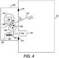
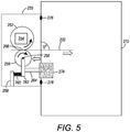
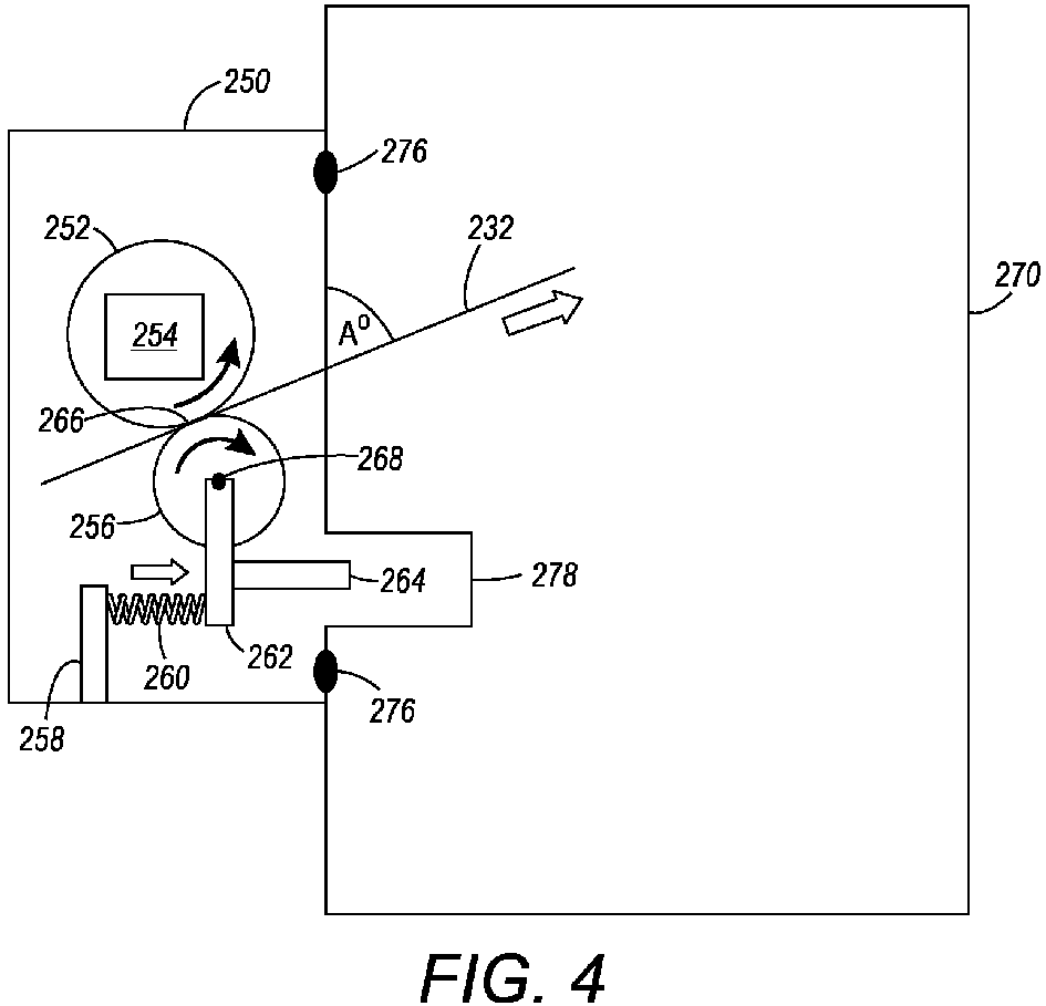
- Figures 4 and 5 illustrate the same offset shuttle roll assembly 250; however, in Figure 4 the offset shuttle roll assembly 250 is connected to a center-tray machine that requires planar media 232 be supplied at an upward angle (A°), while in Figure 5 the offset shuttle roll assembly 250 is connected to a finisher transport machine that requires planar media 232 be supplied at a flat angle (B°).
- a first exit direction at which the planar media 232 exits nip 266 is at a first angle relative to (and outward from) the planar exterior surface of the offset shuttle roll assembly 250 (e.g., upward angle (A°)) as shown in Figures 2 and 4 , and can be for example, any angle other than approximately 85°-95° (e.g., can be 0°-84° or 96°-180°).
- A° upward angle
- a second exit direction at which the planar media 232 exits nip 266 is at a second different angle relative to (and outward from) the planar exterior surface of the offset shuttle roll assembly 250 (e.g., flat angle (B°)) as shown in Figures 3 and 5 , and can be for example, approximately 85°-95°.
- the first and second exit directions can be any angles (0°-180°) relative to the planar exterior surface of the offset shuttle roll assembly 250, so long as the first and second exit directions are different by at least a minimum angular difference (e.g., 10°, 15°, 30°, 45° difference in angles A° and B°).
- the offset shuttle roll assembly 250 can be connected to a first machine 270 (e.g., such as a center-tray machine) or a second machine 272 (e.g., such as a finisher transport machine) without modifying the offset shuttle roll assembly 250 in any way.
- the first machine 270 and the second machine 272 can be any types of machines that have different processing functions and/or that require planar media 232 be supplied at different angles.
- Such structures can further include mounting points 276 connecting the offset shuttle roll assembly 250 to the first machine 270 and the second machine 272.
- the first machine 270 and the second machine 272 have identical receptor points (also shown using identification numeral 276) connected to the mounting points 276, so the offset shuttle roll assembly 250 can easily be connected to either the first or second machine using the same mounting point and receptor point locations 276.
- the first machine 270 has void areas 278 positioned to allow movement of the adjusters 264 in the first direction (as shown by the block arrows in Figure 4 ) when the offset shuttle roll assembly 250 is connected to the first machine 270.
- These void areas 278 allow the biasing members 260 to position the adjusters 264 in the second position ( Figure 4 ) when the offset shuttle roll assembly 250 is connected to the first machine 270 to also position the moveable roller 256 in the second position ( Figure 4 ), which results in the exit nip 266 transporting the planar media 232 in the second exit direction (e.g., upward angle (A°)).
- the second machine 272 has contact areas 274 positioned to contact the adjusters 264 when the offset shuttle roll assembly 250 is connected to the second machine 272.
- the contact areas 274 hold the adjusters 264 in the first position ( Figure 5 ) against biasing forces exerted by the biasing members 260, as shown by the block arrow in Figure 5 .
- Such contact areas 274 hold the adjusters 264 in the first position ( Figure 5 ) when the offset shuttle roll assembly 250 is connected to the second machine 272 to position the moveable roller 256 in the first position ( Figure 5 ), which results in the exit nip 266 transporting the planar media 232 in the first exit direction (e.g., flat angle (B°)) that is different from the second exit direction.
- Computerized devices that include chip-based central processing units (CPU's), input/output devices (including graphic user interfaces (GUI), memories, comparators, tangible processors, etc.) are well-known and readily available devices produced by manufacturers such as Dell Computers, Round Rock TX, USA and Apple Computer Co., Cupertino CA, USA.
- Such computerized devices commonly include input/output devices, power supplies, tangible processors, electronic storage memories, wiring, etc., the details of which are omitted herefrom to allow the reader to focus on the salient aspects of the devices described herein.
- printers, copiers, scanners and other similar peripheral equipment are available from Xerox Corporation, Norwalk, CT, USA and the details of such devices are not discussed herein for purposes of brevity and reader focus.
- printer or printing device encompasses any apparatus, such as a digital copier, bookmaking machine, facsimile machine, multi-function machine, etc., which performs a print outputting function for any purpose.
- the details of printers, printing engines, etc. are well-known and are not described in detail herein to keep this disclosure focused on the salient features presented.
- the devices herein can encompass devices that print in color, monochrome, or handle color or monochrome image data. All foregoing devices are specifically applicable to electrostatographic and/or xerographic machines and/or processes.
Landscapes
- Engineering & Computer Science (AREA)
- Mechanical Engineering (AREA)
- Delivering By Means Of Belts And Rollers (AREA)
Abstract


Description
- Devices herein generally relate to those that utilize rollers to form nips for transporting sheets of media, and more particularly to components that have nips that direct sheets of media to exit a device.
- Complex machines are formed of many diverse components, and often many individual components are combined into assemblies that perform a specific function. Assemblies can be interchangeably used in different device models, which adds efficiency to manufacturing operations.
- In one example of an assembly, two or more flat, elongated rolls or rollers (at least one of which is driven) are positioned in a sheet feeding assembly to be in contact so as to form a nip that drives flat items, such as continuous-feed webs, or cut sheets, of print media (paper, transparencies, plastic, metal, cloth, etc.). An exit roll assembly (e.g., an offset shuttle roll assembly) is often used as a component of a larger machine, such as a printer, copier, scanner, multi-function printing device, etc., to perform the function of causing printed flat print media to exit the larger sheet-handling machine.
- However, sometimes a sheet-handling machine can produce sheets that exit to more than one type of device. In one example, the sheets exiting a printing device can be driven by the nip of an exit roll assembly to a finisher transport (FT) device or a center tray (CT) device. Sheets are fed to finisher transport device at a different angle from sheets that are fed to a center tray device and, therefore, different offset shuttle roll assemblies are sometimes used in the same model sheet handling device based on whether that sheet handling device will be connected to a finisher transport device or a center tray device.
- The proliferation of different types of assemblies adds complexity, and can result in the wrong type of assembly being utilized. Incorrect assembly usage prevents proper device operation, which wastes time and device resources and decreases user satisfaction.
- Exemplary apparatuses herein include, among other components, a movable roller, a fixed-position roller contacting the movable roller to form an exit nip transporting planar media, biasing members operatively (meaning directly or indirectly) connected to the movable roller, and adjusters contacting the movable roller.
- The biasing members force the movable roller in a first direction relative to the fixed-position roller to move the movable roller from a first position to a second position. The adjusters move from the first position to the second position with the movable roller. The movable roller contacts the fixed-position roller in both the first position and the second position. The apparatus are connectable to a first machine or a second machine.
- The first machine has contact areas positioned to contact the adjusters when the apparatus is connected to the first machine. The contact areas hold the adjusters in the first position when the apparatus is connected to the first machine to position the movable roller in the first position resulting in the exit nip transporting the planar media in a first exit direction. The second machine instead has void areas positioned to allow movement of the adjusters in the first direction when the apparatus is connected to the second machine. The void areas allow the biasing members to position the adjusters in the second position when the apparatus is connected to the second machine to position the movable roller in the second position resulting in the exit nip transporting the planar media in a second exit direction different from the first exit direction.
- Different exemplary apparatuses (e.g., such as an offset shuttle roll assembly) herein include, among other components, a movable roller, a fixed-position roller contacting the movable roller to form an exit nip transporting planar media, movable mounting features connected to the movable roller, fixed mounting features connected to the fixed-position roller, biasing members connected to the movable mounting features, and adjusters (e.g., such as plungers) contacting the movable mounting features. The movable roller has a first axle connected to the movable mounting features about which the movable roller rotates and the fixed-position roller has a second axle connected to the fixed mounting features about which the fixed-position roller rotates. Additionally, the apparatuses can include a motor, connected to or as part of the fixed mounting features that rotate the fixed-position roller.
- The biasing members force the movable mounting features in a first direction relative to the fixed mounting features, and the biasing members move the movable roller from a first position to a second position in the first direction by moving the movable mounting features. Both the movable mounting features and the adjusters move from the first position to the second position with the movable roller. The movable roller contacts the fixed-position roller in both the first position and the second position.
- The apparatus can be connected to a first machine (e.g., such as a center-tray machine) or a second machine (e.g., such as a finisher transport machine). The first machine has a different processing function from the second machine. Such structures can further include mounting points connecting the apparatus to the first machine and the second machine. The first machine and the second machine have identical receptor points connected to the mounting points, so the apparatus can easily be connected to either the first or second machine using the same mounting point and receptor point locations.
- The first machine has contact areas positioned to contact the adjusters when the apparatus is connected to the first machine. The contact areas hold the adjusters in the first position against biasing forces exerted by the biasing members. Such contact areas hold the adjusters in the first position when the apparatus is connected to the first machine to position the movable roller in the first position, which results in the exit nip transporting the planar media in a first exit direction.
- The second machine instead has void areas positioned to allow movement of the adjusters in the first direction when the apparatus is connected to the second machine. These void areas allow the biasing members to position the adjusters in the second position when the apparatus is connected to the second machine to position the movable roller in the second position, which results in the exit nip transporting the planar media in a second exit direction different from the first exit direction.
- More specifically, the first exit direction is at a first angle relative to and outward from the planar exterior surface of the apparatus. The second exit direction is at a second angle relative to and outward from the planar exterior surface. The first angle is different from the second angle.
- These and other features are described in, or are apparent from, the following detailed description.
- Various exemplary devices are described in detail below, with reference to the attached drawing figures, in which:
-
Figure 1 is a schematic diagram illustrating devices herein; -
Figure 2 is a schematic diagram illustrating devices herein; -
Figure 3 is a schematic diagram illustrating devices herein; -
Figure 4 is a schematic diagram illustrating devices herein; and -
Figure 5 is a schematic diagram illustrating devices herein. - As mentioned above, sheets are fed to finisher transport (FT) device at a different angle from sheets that are fed to a center tray (CT) device (e.g., 0 degrees and 20 degrees respectively) and, therefore, different offset shuttle roll assemblies are used in sheet handling devices based on whether the sheet handling device will be connected to a finisher transport device or a center tray device. However, incorrect assembly usage prevents proper device operation, which wastes time and device resources and decreases user satisfaction.
- Instead of having different assemblies for different post-sheet exit configurations, the devices herein incorporate multiple sheet exit angle exit positions in a single type of self-setting/adjusting assembly. This allows only one type of assembly to be manufactured, and no further change of that assembly is made, regardless of the type of post-printing processing device that is connected to the large printing machine maintaining the assembly.
- In one non-limiting example, instead of having different offset roll assemblies for use with finisher transport and center tray post-printing devices, the assemblies herein incorporate both positions (0 and 20 degrees) in a self-setting/adjusting roll assembly mechanism so that only one type of roll assembly is manufactured, and no further change of that roll assembly is made, regardless of whether the large machine maintaining the assembly is fitted to a finisher transport or center tray unit. While offset roll assemblies, finisher transport devices, and center tray devices are used in the examples herein, those ordinarily skilled in the art would understand that the features described herein are to be used with any type of driven-nip sheet-handling assembly and such structures are not limited to being used only with offset roll assemblies, finisher transport devices, center tray devices, etc.
- Having different assemblies wastes installation time, and also leaves open the potential of incorrect assembly fitment by the rigger. However with the single self-setting assemblies described herein (that are added to the machine during original manufacture at the factory, and are not later fitted by an in-field rigger) many types of post-printing devices can be attached to a printing machine in the field by the rigger, without any adjustment of the sheet exit assembly being performed in the field because the sheet exit assemblies described herein self-set to the correct angle.
- With sheet exit assemblies described herein, for example, in center tray mode, the roll assembly is outwardly sprung at a 20 degree angle position, sending the output sheets upwards by 20 degrees on the exit into a tray. However, in finisher transport mode is to be fitted, the roll assembly is located with pressure exerted against two plungers, which push the sprung loaded roll assembly back to a stop, which leaves the rolls at a zero degree angle.
-
Figure 1 illustrates aprinting device 204, which can be used with devices herein and can comprise, for example, a printer, copier, multi-function machine, multi-function device (MFD), etc. Theprinting device 204 includes a controller/tangible processor 224 and a communications port (input/output) 214 operatively connected to thetangible processor 224 and to the computerized network external to theprinting device 204. Also, theprinting device 204 can include at least one accessory functional component, such as a graphical user interface (GUI)assembly 212. The user may receive messages, instructions, and menu options from, and enter instructions through, the graphical user interface orcontrol panel 212. - The input/
output device 214 is used for communications to and from theprinting device 204 and comprises a wired device or wireless device (of any form, whether currently known or developed in the future). Thetangible processor 224 controls the various actions of the computerized device. A non-transitory, tangible, computer storage medium device 210 (which can be optical, magnetic, capacitor based, etc., and is different from a transitory signal) is readable by thetangible processor 224 and stores instructions that thetangible processor 224 executes to allow the computerized device to perform its various functions, such as those described herein. Thus, as shown inFigure 1 , a body housing has one or more functional components that operate on power supplied from an alternating current (AC)source 220 by thepower supply 218. Thepower supply 218 can comprise a common power conversion unit, power storage element (e.g., a battery, etc), etc. - The
printing device 204 also includes at least one marking device (printing engine(s)) 240 operatively connected to a specialized image processor 224 (that is different from a general purpose computer because it is specialized for processing image data), amedia path 236 positioned to supply continuous media or sheets of media from asheet supply 230 to the marking device(s) 240, etc. After receiving various markings from the printing engine(s) 240, the sheets of media can optionally pass to a finisher which can fold, staple, sort, etc., the various printed sheets. Also, theprinting device 204 can include at least one accessory functional component (such as a scanner/document handler 280 (automatic document feeder (ADF)), etc.) that also operate on the power supplied from the external power source 220 (through the power supply 218). - The one or
more printing engines 240 are intended to illustrate any marking device that applies a marking material (toner, inks, etc.) to continuous media or sheets of media, whether currently known or developed in the future and can include, for example, devices that use a photoreceptor belt or an intermediate transfer belt, or devices that print directly to print media (e.g., inkjet printers, ribbon-based contact printers, etc.). - Additionally,
Figure 1 illustrates different machines connected to theprinter 204 that receive printed sheets from ashuttle roll assembly 250 of the printer, and such machines can include, for example, a first machine 270 (e.g., such as a center-tray machine) or a second machine 272 (e.g., such as a finisher transport machine), etc. - As shown in greater detail in
Figures 2-3 , the apparatus(es) 250 shown inFigure 1 (e.g., such as an offset shuttle roll assembly 250) include, among other components, amoveable roller 256, a fixed-position roller 252 contacting themoveable roller 256 to form an exit nip 266 transportingplanar media 232, movable mounting feature(s) 262 connected to themoveable roller 256, fixed mounting feature(s) 254 connected to the fixed-position roller 252, biasing member(s) 260 (such as springs, elastic bands, pistons, biased beams, actuators, magnetic structures, electrically biased structures, etc.) connected to fixed mountingpoints 258 and the movable mounting features 262, and adjuster(s) 264 (e.g., such as (hollow or solid) plungers, cylinders, rods, needles, beams, posts, arms, connectors, etc.) contacting the movable mounting features 262. - The
moveable roller 256 has afirst axle 268 connected to the movable mounting features 262 about which themoveable roller 256 rotates (as shown by the block arrow in the drawing) and the fixed-position roller 252 has asecond axle 254 connected to the fixed mounting features 254 about which the fixed-position roller 252 rotates (as also shown by the block arrow in the drawing) to move themedia sheet 232 in the direction shown by the block arrow. Additionally, the second axle can include or be attached to a motor (that is connected to or is part of the fixed mounting features) that rotates the fixed-position roller 252; and for ease of illustration the fixed mounting feature, second axle, and motor are represented in the drawing as asingle item 254. -
Figures 2 and 3 illustrate the same offsetshuttle roll assembly 250; however, inFigure 3 the biasingmember 260 is compressed, while inFigure 2 the biasingmember 260 is expanded which moves the movable mounting features 262, theadjusters 264, and themovable roller 256. Thus, the biasingmembers 260 force the movable mounting features 262 in a first direction (shown by the block arrow inFigure 2 ) relative to the fixed mounting features 254. As shown, the biasingmembers 260 move themoveable roller 256 from a first position (shown inFigure 3 ) to a second position (shown inFigure 2 ) in a first direction (block arrow,Figure 2 ) by moving the movable mounting features 262. Both the movable mounting features 262 and theadjusters 264 move from the first position (Figure 3 ) to the second position (Figure 2 ) with themoveable roller 256. Themoveable roller 256 contacts the fixed-position roller 252 in both the first position (Figure 3 ) and the second position (Figure 2 ). -
Figures 4 and5 illustrate the same offsetshuttle roll assembly 250; however, inFigure 4 the offsetshuttle roll assembly 250 is connected to a center-tray machine that requiresplanar media 232 be supplied at an upward angle (A°), while inFigure 5 the offsetshuttle roll assembly 250 is connected to a finisher transport machine that requiresplanar media 232 be supplied at a flat angle (B°). More specifically, a first exit direction at which theplanar media 232 exits nip 266 is at a first angle relative to (and outward from) the planar exterior surface of the offset shuttle roll assembly 250 (e.g., upward angle (A°)) as shown inFigures 2 and4 , and can be for example, any angle other than approximately 85°-95° (e.g., can be 0°-84° or 96°-180°). Also, a second exit direction at which theplanar media 232 exits nip 266 is at a second different angle relative to (and outward from) the planar exterior surface of the offset shuttle roll assembly 250 (e.g., flat angle (B°)) as shown inFigures 3 and5 , and can be for example, approximately 85°-95°. In other offsetshuttle roll assemblies 250 herein, the first and second exit directions can be any angles (0°-180°) relative to the planar exterior surface of the offsetshuttle roll assembly 250, so long as the first and second exit directions are different by at least a minimum angular difference (e.g., 10°, 15°, 30°, 45° difference in angles A° and B°). - Thus, as shown in
Figures 4-5 , the offsetshuttle roll assembly 250 can be connected to a first machine 270 (e.g., such as a center-tray machine) or a second machine 272 (e.g., such as a finisher transport machine) without modifying the offsetshuttle roll assembly 250 in any way. Thefirst machine 270 and thesecond machine 272 can be any types of machines that have different processing functions and/or that requireplanar media 232 be supplied at different angles. - Such structures can further include mounting
points 276 connecting the offsetshuttle roll assembly 250 to thefirst machine 270 and thesecond machine 272. Thefirst machine 270 and thesecond machine 272 have identical receptor points (also shown using identification numeral 276) connected to the mountingpoints 276, so the offsetshuttle roll assembly 250 can easily be connected to either the first or second machine using the same mounting point andreceptor point locations 276. - As shown in
Figure 4 , thefirst machine 270 has voidareas 278 positioned to allow movement of theadjusters 264 in the first direction (as shown by the block arrows inFigure 4 ) when the offsetshuttle roll assembly 250 is connected to thefirst machine 270. Thesevoid areas 278 allow the biasingmembers 260 to position theadjusters 264 in the second position (Figure 4 ) when the offsetshuttle roll assembly 250 is connected to thefirst machine 270 to also position themoveable roller 256 in the second position (Figure 4 ), which results in the exit nip 266 transporting theplanar media 232 in the second exit direction (e.g., upward angle (A°)). - As shown in
Figure 5 , thesecond machine 272 hascontact areas 274 positioned to contact theadjusters 264 when the offsetshuttle roll assembly 250 is connected to thesecond machine 272. Thecontact areas 274 hold theadjusters 264 in the first position (Figure 5 ) against biasing forces exerted by the biasingmembers 260, as shown by the block arrow inFigure 5 .Such contact areas 274 hold theadjusters 264 in the first position (Figure 5 ) when the offsetshuttle roll assembly 250 is connected to thesecond machine 272 to position themoveable roller 256 in the first position (Figure 5 ), which results in the exit nip 266 transporting theplanar media 232 in the first exit direction (e.g., flat angle (B°)) that is different from the second exit direction. - While some exemplary structures are illustrated in the attached drawings, those ordinarily skilled in the art would understand that the drawings are simplified schematic illustrations and that the claims presented below encompass many more features that are not illustrated (or potentially many less) but that are commonly utilized with such devices and systems. Therefore, Applicants do not intend for the claims presented below to be limited by the attached drawings, but instead the attached drawings are merely provided to illustrate a few ways in which the claimed features can be implemented.
- Many computerized devices are discussed above. Computerized devices that include chip-based central processing units (CPU's), input/output devices (including graphic user interfaces (GUI), memories, comparators, tangible processors, etc.) are well-known and readily available devices produced by manufacturers such as Dell Computers, Round Rock TX, USA and Apple Computer Co., Cupertino CA, USA. Such computerized devices commonly include input/output devices, power supplies, tangible processors, electronic storage memories, wiring, etc., the details of which are omitted herefrom to allow the reader to focus on the salient aspects of the devices described herein. Similarly, printers, copiers, scanners and other similar peripheral equipment are available from Xerox Corporation, Norwalk, CT, USA and the details of such devices are not discussed herein for purposes of brevity and reader focus.
- The terms printer or printing device as used herein encompasses any apparatus, such as a digital copier, bookmaking machine, facsimile machine, multi-function machine, etc., which performs a print outputting function for any purpose.
The details of printers, printing engines, etc., are well-known and are not described in detail herein to keep this disclosure focused on the salient features presented. The devices herein can encompass devices that print in color, monochrome, or handle color or monochrome image data. All foregoing devices are specifically applicable to electrostatographic and/or xerographic machines and/or processes. - In addition, terms such as "right", "left", "vertical", "horizontal", "top", "bottom", "upper", "lower", "under", "below", "underlying", "over", "overlying", "parallel", "perpendicular", etc., used herein are understood to be relative locations as they are oriented and illustrated in the drawings (unless otherwise indicated). Terms such as "touching", "on", "in direct contact", "abutting", "directly adjacent to", etc., mean that at least one element physically contacts another element (without other elements separating the described elements). Further, the terms automated or automatically mean that once a process is started (by a machine or a user); one or more machines perform the process without further input from any user. In the drawings herein, the same identification numeral identifies the same or similar item.
- It will be appreciated that the above-disclosed and other features and functions, or alternatives thereof, may be desirably combined into many other different systems or applications. Various presently unforeseen or unanticipated alternatives, modifications, variations, or improvements therein may be subsequently made by those skilled in the art which are also intended to be encompassed by the following claims. Unless specifically defined in a specific claim itself, steps or components of the devices herein cannot be implied or imported from any above example as limitations to any particular order, number, position, size, shape, angle, color, or material.
Claims (10)
- An apparatus comprising:a movable roller;a fixed-position roller contacting said movable roller to form an exit nip transporting planar media;biasing members operatively connected to said movable roller; andadjusters contacting said movable roller,said biasing members forcing said movable roller in a first direction relative to said fixed-position roller to move said movable roller from a first position to a second position,said adjusters moving from said first position to said second position with said movable roller,said movable roller contacting said fixed-position roller in both said first position and said second position,said apparatus being connectable to a first machine or to a second machine,said first machine having contact areas positioned to contact said adjusters when said apparatus is connected to said first machine,said contact areas holding said adjusters in said first position when said apparatus is connected to said first machine to position said movable roller in said first position resulting in said exit nip transporting said planar media in a first exit direction,said second machine having void areas positioned to allow movement of said adjusters in said first direction when said apparatus is connected to said second machine, andsaid void areas allowing said biasing members to position said adjusters in said second position when said apparatus is connected to said second machine to position said movable roller in said second position resulting in said exit nip transporting said planar media in a second exit direction different from said first exit direction.
- The apparatus according to claim 1, further comprising a planar exterior surface,
said first exit direction being at a first angle relative to and outward from said planar exterior surface,
said second exit direction being at a second angle relative to and outward from said planar exterior surface, and
said first angle being different from said second angle. - The apparatus according to claim 1, said contact areas holding said adjusters in said first position against biasing forces exerted by said biasing members.
- The apparatus according to claim 1, said first machine having a different processing function from said second machine.
- An apparatus comprising:a movable roller;a fixed-position roller contacting said movable roller to form an exit nip transporting planar media;movable mounting features connected to said movable roller;fixed mounting features connected to said fixed-position roller;biasing members connected to said movable mounting features; andadjusters contacting said movable mounting features,said biasing members forcing said movable mounting features in a first direction relative to said fixed mounting features,said biasing members moving said movable roller from a first position to a second position in said first direction by moving said movable mounting features,said movable mounting features and said adjusters moving from said first position to said second position with said movable roller,said movable roller contacting said fixed-position roller in both said first position and said second position,said apparatus being connectable to a first machine or to a second machine,said first machine having contact areas positioned to contact said adjusters when said apparatus is connected to said first machine,said contact areas holding said adjusters in said first position when said apparatus is connected to said first machine to position said movable roller in said first position resulting in said exit nip transporting said planar media in a first exit direction,said second machine having void areas positioned to allow movement of said adjusters in said first direction when said apparatus is connected to said second machine, andsaid void areas allowing said biasing members to position said adjusters in said second position when said apparatus is connected to said second machine to position said movable roller in said second position resulting in said exit nip transporting said planar media in a second exit direction different from said first exit direction.
- The apparatus according to claim 5, further comprising a planar exterior surface,
said first exit direction being at a first angle relative to and outward from said planar exterior surface,
said second exit direction being at a second angle relative to and outward from said planar exterior surface, and
said first angle being different from said second angle. - The apparatus according to claim 5, said contact areas holding said adjusters in said first position against biasing forces exerted by said biasing members.
- The apparatus according to claim 5, said first machine having a different processing function from said second machine.
- An offset shuttle roll assembly comprising:a movable roller;a fixed-position roller contacting said movable roller to form an exit nip transporting planar media;movable mounting features connected to said movable roller;fixed mounting features connected to said fixed-position roller;springs connected to said movable mounting features; andplungers contacting said movable mounting features,said springs forcing said movable mounting features in a first direction relative to said fixed mounting features,said springs moving said movable roller from a first position to a second position in said first direction by moving said movable mounting features,said movable mounting features and said plungers moving from said first position to said second position with said movable roller,said movable roller contacting said fixed-position roller in both said first position and said second position,said offset shuttle roll assembly being connectable to a center-tray machine or to a finisher transport machine,said center-tray machine having contact areas positioned to contact said plungers when said offset shuttle roll assembly is connected to said center-tray machine,said contact areas holding said plungers in said first position when said offset shuttle roll assembly is connected to said center-tray machine to position said movable roller in said first position resulting in said exit nip transporting said planar media in a first exit angle from said offset shuttle roll assembly,said finisher transport machine having void areas positioned to allow movement of said plungers in said first direction when said offset shuttle roll assembly is connected to said finisher transport machine, andsaid void areas allowing said springs to position said plungers in said second position when said offset shuttle roll assembly is connected to said finisher transport machine to position said movable roller in said second position resulting in said exit nip transporting said planar media in a second exit angle from said offset shuttle roll assembly different from said first exit angle from said offset shuttle roll assembly.
- The offset shuttle roll assembly according to claim 9, further comprising a planar exterior surface,
said first exit angle from said offset shuttle roll assembly being at a first angle relative to and outward from said planar exterior surface,
said second exit angle from said offset shuttle roll assembly being at a second angle relative to and outward from said planar exterior surface, and
said first angle being different from said second angle.
Applications Claiming Priority (1)
| Application Number | Priority Date | Filing Date | Title |
|---|---|---|---|
| US14/883,087 US9550647B1 (en) | 2015-10-14 | 2015-10-14 | Self-setting exit roll assembly |
Publications (1)
| Publication Number | Publication Date |
|---|---|
| EP3156357A1 true EP3156357A1 (en) | 2017-04-19 |
Family
ID=57047098
Family Applications (1)
| Application Number | Title | Priority Date | Filing Date |
|---|---|---|---|
| EP16192111.9A Withdrawn EP3156357A1 (en) | 2015-10-14 | 2016-10-03 | Exit roll assembly |
Country Status (3)
| Country | Link |
|---|---|
| US (1) | US9550647B1 (en) |
| EP (1) | EP3156357A1 (en) |
| JP (1) | JP2017075056A (en) |
Families Citing this family (1)
| Publication number | Priority date | Publication date | Assignee | Title |
|---|---|---|---|---|
| JP5976038B2 (en) * | 2014-06-04 | 2016-08-23 | 京セラドキュメントソリューションズ株式会社 | Sheet processing apparatus and image forming apparatus having the same |
Citations (2)
| Publication number | Priority date | Publication date | Assignee | Title |
|---|---|---|---|---|
| US5326093A (en) * | 1993-05-24 | 1994-07-05 | Xerox Corporation | Universal interface module interconnecting various copiers and printers with various sheet output processors |
| US20090190983A1 (en) * | 2008-01-29 | 2009-07-30 | Noritsu Koki Co., Ltd. | Decurling mechanism |
Family Cites Families (22)
| Publication number | Priority date | Publication date | Assignee | Title |
|---|---|---|---|---|
| US3848788A (en) | 1973-07-23 | 1974-11-19 | Paxon Machine Co | Continuous strip feeding self-alignment apparatus |
| US5210616A (en) * | 1989-06-30 | 1993-05-11 | Canon Kabushiki Kaisha | Sheet carrier apparatus and a picture image recording apparatus |
| US5014976A (en) | 1990-04-04 | 1991-05-14 | Xerox Corporation | Exit roller shield for duplex printing |
| US5215298A (en) * | 1992-06-24 | 1993-06-01 | Xerox Corporation | Orbiting nip sheet output with faceup or facedown stacking and integral gate |
| US5201517A (en) | 1992-06-24 | 1993-04-13 | Xerox Corporation | Orbiting nip plural mode sheet output with faceup or facedown stacking |
| US5273273A (en) | 1992-11-27 | 1993-12-28 | Eastman Kodak Company | Sheet inverting mechanism having dual drive assemblies |
| JP3058788B2 (en) | 1993-12-29 | 2000-07-04 | ニスカ株式会社 | Automatic document feeder |
| US6390287B2 (en) | 1999-06-10 | 2002-05-21 | The Robbins Company | Self-adjusting carrying idler assembly |
| US6431397B1 (en) | 2000-06-09 | 2002-08-13 | Sherman S. Fishman | Method and means for dispensing releasable labels from roll-stock substrate |
| JP4086525B2 (en) | 2001-04-16 | 2008-05-14 | 株式会社リコー | Sheet conveying apparatus and image forming apparatus |
| US7244072B2 (en) | 2004-10-29 | 2007-07-17 | Eastman Kodak Company | Sheet recording apparatus with dual nip transport |
| TWI252837B (en) * | 2005-03-11 | 2006-04-11 | Lite On Technology Corp | Paper feeding device and method for flipping paper for same |
| US7637490B2 (en) | 2005-10-03 | 2009-12-29 | Bowe Bell + Howell Company | Inserting systems and methods |
| JP2010037044A (en) * | 2008-08-04 | 2010-02-18 | Fuji Xerox Co Ltd | Medium ejecting device and image forming device |
| JP5705419B2 (en) | 2009-06-03 | 2015-04-22 | 株式会社リコー | Image forming apparatus |
| JP5523225B2 (en) * | 2010-07-05 | 2014-06-18 | 日本電産サンキョー株式会社 | Medium transport direction switching mechanism and medium issue / collection device |
| US8328195B2 (en) | 2010-10-07 | 2012-12-11 | Lexmark International, Inc. | Exit path assembly for an imaging device |
| US9079739B2 (en) | 2012-11-02 | 2015-07-14 | The Procter & Gamble Company | Apparatus for controlling the nip force/pressure between two rotating cylinders |
| CN104097965A (en) * | 2013-04-11 | 2014-10-15 | 致伸科技股份有限公司 | Deflection roller device for paper conveying and method for changing paper conveying path |
| JP2015182883A (en) * | 2014-03-26 | 2015-10-22 | 富士ゼロックス株式会社 | Recording material discharging device, and recording material processing apparatus using the same |
| US9132979B1 (en) * | 2014-05-06 | 2015-09-15 | Xerox Corporation | Shuttling nip set for media sheet inversion |
| JP6296903B2 (en) * | 2014-05-30 | 2018-03-20 | 理想科学工業株式会社 | Paper discharge device |
-
2015
- 2015-10-14 US US14/883,087 patent/US9550647B1/en not_active Expired - Fee Related
-
2016
- 2016-09-30 JP JP2016194800A patent/JP2017075056A/en active Pending
- 2016-10-03 EP EP16192111.9A patent/EP3156357A1/en not_active Withdrawn
Patent Citations (2)
| Publication number | Priority date | Publication date | Assignee | Title |
|---|---|---|---|---|
| US5326093A (en) * | 1993-05-24 | 1994-07-05 | Xerox Corporation | Universal interface module interconnecting various copiers and printers with various sheet output processors |
| US20090190983A1 (en) * | 2008-01-29 | 2009-07-30 | Noritsu Koki Co., Ltd. | Decurling mechanism |
Also Published As
| Publication number | Publication date |
|---|---|
| JP2017075056A (en) | 2017-04-20 |
| US9550647B1 (en) | 2017-01-24 |
Similar Documents
| Publication | Publication Date | Title |
|---|---|---|
| US8538306B2 (en) | Web feed system having compensation roll | |
| US10289050B2 (en) | Binding device including binders associated with different maximum bundle thicknesses and image forming apparatus incorporating same | |
| US9781283B1 (en) | Document handler having integrated platen and fully internal CVT path | |
| US9236677B2 (en) | Spring power contact having non-linear slot | |
| US9845218B2 (en) | Folding device, post-processing device and image forming apparatus | |
| US10022885B2 (en) | Punching device, image forming apparatus, and punching method | |
| JP6564724B2 (en) | Apparatus provided with conveying belt, sheet drying apparatus, and printing apparatus | |
| US11738959B2 (en) | Sheet registration using rotatable frame | |
| US9341466B1 (en) | Sheet height sensor using movable and stationary mirrors | |
| US20110188872A1 (en) | Fixing device and image forming apparatus | |
| US9550647B1 (en) | Self-setting exit roll assembly | |
| US9077939B1 (en) | Extension color gamut queue | |
| US9309074B1 (en) | Sheet height sensor and adjuster | |
| US9906665B1 (en) | Document handler having opposing belts maintaining constant sheet contact for scanning small and delicate sheets | |
| US8925458B2 (en) | Cleaning structure and method for friction roll feeders | |
| US9604478B1 (en) | Print media beam strength sensor | |
| US8695972B2 (en) | Inverter with adjustable reversing roll position | |
| US9938108B2 (en) | Sheet processing apparatus and image forming system | |
| US9971291B2 (en) | Media deskew using variable buckle based on printing characteristic | |
| US9110408B1 (en) | Adjusting tone reproduction curve and belt tension to control printing errors | |
| US8520272B1 (en) | Sheet feeder having curved calibration strip | |
| US11407605B2 (en) | Air-based photoreceptor sheet stripper | |
| US9551969B2 (en) | Deskew mechanism with linear motion | |
| US8844920B1 (en) | Stapler producing high precision alignment stacking of unstapled sheets | |
| US11338570B2 (en) | Sheet detection circuit using electrical elements contacting conductive vacuum belt |
Legal Events
| Date | Code | Title | Description |
|---|---|---|---|
| PUAI | Public reference made under article 153(3) epc to a published international application that has entered the european phase |
Free format text: ORIGINAL CODE: 0009012 |
|
| STAA | Information on the status of an ep patent application or granted ep patent |
Free format text: STATUS: THE APPLICATION HAS BEEN PUBLISHED |
|
| AK | Designated contracting states |
Kind code of ref document: A1 Designated state(s): AL AT BE BG CH CY CZ DE DK EE ES FI FR GB GR HR HU IE IS IT LI LT LU LV MC MK MT NL NO PL PT RO RS SE SI SK SM TR |
|
| AX | Request for extension of the european patent |
Extension state: BA ME |
|
| STAA | Information on the status of an ep patent application or granted ep patent |
Free format text: STATUS: REQUEST FOR EXAMINATION WAS MADE |
|
| 17P | Request for examination filed |
Effective date: 20171019 |
|
| RBV | Designated contracting states (corrected) |
Designated state(s): AL AT BE BG CH CY CZ DE DK EE ES FI FR GB GR HR HU IE IS IT LI LT LU LV MC MK MT NL NO PL PT RO RS SE SI SK SM TR |
|
| STAA | Information on the status of an ep patent application or granted ep patent |
Free format text: STATUS: THE APPLICATION IS DEEMED TO BE WITHDRAWN |
|
| 18D | Application deemed to be withdrawn |
Effective date: 20190501 |