EP3156134A1 - Centrifugal separator with intermittent discharge of heavy phase - Google Patents
Centrifugal separator with intermittent discharge of heavy phase Download PDFInfo
- Publication number
- EP3156134A1 EP3156134A1 EP15189390.6A EP15189390A EP3156134A1 EP 3156134 A1 EP3156134 A1 EP 3156134A1 EP 15189390 A EP15189390 A EP 15189390A EP 3156134 A1 EP3156134 A1 EP 3156134A1
- Authority
- EP
- European Patent Office
- Prior art keywords
- rotor
- space
- centrifugal separator
- paring
- seal
- Prior art date
- Legal status (The legal status is an assumption and is not a legal conclusion. Google has not performed a legal analysis and makes no representation as to the accuracy of the status listed.)
- Granted
Links
Images


Classifications
-
- B—PERFORMING OPERATIONS; TRANSPORTING
- B04—CENTRIFUGAL APPARATUS OR MACHINES FOR CARRYING-OUT PHYSICAL OR CHEMICAL PROCESSES
- B04B—CENTRIFUGES
- B04B1/00—Centrifuges with rotary bowls provided with solid jackets for separating predominantly liquid mixtures with or without solid particles
- B04B1/10—Centrifuges with rotary bowls provided with solid jackets for separating predominantly liquid mixtures with or without solid particles with discharging outlets in the plane of the maximum diameter of the bowl
- B04B1/14—Centrifuges with rotary bowls provided with solid jackets for separating predominantly liquid mixtures with or without solid particles with discharging outlets in the plane of the maximum diameter of the bowl with periodical discharge
-
- B—PERFORMING OPERATIONS; TRANSPORTING
- B04—CENTRIFUGAL APPARATUS OR MACHINES FOR CARRYING-OUT PHYSICAL OR CHEMICAL PROCESSES
- B04B—CENTRIFUGES
- B04B7/00—Elements of centrifuges
- B04B7/02—Casings; Lids
Definitions
- the invention relates to a centrifugal separator with intermittent discharge of heavy phase
- the energy consumption can be lowered by creating an under pressure around the rotor, i.e. the separator bowl.
- a sealing is used today between the machine top part and the separator casing. This sealing is expensive and not always robust and thus not completely reliable.
- centrifugal separator for separating a fluid mixture into components.
- the centrifugal separator comprises a casing which delimits a space which is sealed by at least one seal relative the surroundings of the casing; and in which a rotor is fastened to a shaft arranged for rotation around a rotational axis x and forming within itself a separation space, and in which separation space centrifugal separation of at least one higher density component and at least one lower density component from a fluid takes place during operation, into which rotor at least one inlet extends for introducing said fluid to the separation space, and from which rotor at least one first outlet extends for discharge of at least one component separated from the fluid during operation feed a fluid product to be separated into the separation space, and wherein the rotor comprises at least one second outlet extending from a portion of the separation space to the space for discharge of at least one higher density component separated from the fluid during operation, and wherein said second outlet is arranged for intermittent discharge by an intermittent discharge system and at least one seal is formed by said intermittent discharge system.
- the seal may be a water seal, and may especially be positioned in a paring chamber in said intermittent discharge system.
- the water seal may further be a labyrinth seal in said paring chamber.
- Said labyrinth seal may comprise a stationary paring disc and a rotating wing protrusion arranged in said paring chamber.
- Said stationary paring disc extends outwardly radially into the paring chamber to a first radial position and the wing protrusion extends inwardly radially into the paring chamber to a second radial position and the first radial position is further from the axis than is the second position to such an extent that said stationary paring disc and the wing protrusion form a labyrinth seal.
- the centrifugal separator comprises a non-rotating part 2 and a rotating part 3.
- the non-rotating part 2 comprises a casing 4.
- the rotating part 3 is configured to rotate around the axis of rotation x and comprises a rotatable centrifuge rotor 5 also called centrifuge bowl enclosed by the casing 4, and a shaft 6 to which the centrifuge rotor 5 is attached.
- the centrifuge rotor 5 encloses a separation space 7 in which the separation of a fluid mixture takes place.
- the shaft 6 is a hollow spindle journalled in a bearing arrangement 8 secured to the non-rotating part 2 and driven by a motor 33.
- the hollow spindle functions as an inlet tube 9 with an inlet channel 9a and is arranged to supply a suspension to be separated into separation space 7.
- the suspension comes into contact with a distributor 10 which accelerates the suspension up to same speed as the centrifuge rotor 5.
- the suspension enters the separation space 7 from under the distributor 10 which directs the fluid into a disk set 11, comprising conical separator discs 11 a stacked concentrically outside of the distributor 10. Nearly all the separation is carried out in the spaces between the discs 11 a.
- the heavy phase separated in the disk set 10 forms a layer in the periphery of the separation space 7, while the light phase is collecting radially inside and is further transported out of the separation space 7 to an outlet 12 at the top of the centrifuge rotor 5.
- the bowl comprises a bowl body 13 and a bowl hood 14 connected with each other.
- a plurality of ports 16 arranged for intermittent transport of the heavy phase out of the bowl 5 into a space 17 between the cover 4 and the centrifuge rotor 5.
- an under-pressure in the space 17 is created, possibly near vacuum.
- annular sliding bowl bottom 18 which is axially movable a short distance to and from abutment against a lower annular edge portion 19 of the bowl hood 14 under radial sealing against the bowl body 13 centrally within the centrifuge rotor 5.
- the movement to and from said abutment regulates the free passage from the separation space 7 through the ports 16 to a space between the cover 4 and the centrifuge rotor 5 in such a way that when the sliding bowl bottom 18 abuts against the lower annular edge portion 19 the passage is closed and when the sliding bowl bottom 18 is out of abutment the passage is open.
- a discharge operating system is provided for obtaining this movement of the sliding bowl bottom 18 .
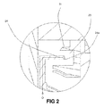
- annular closing chamber 21 from which a constantly open channel 22 extends through the bowl body 13 to an annular paring chamber 23 positioned radially close to the shaft 6 and disclosed in fig. 2 .
- the paring chamber 23 is constantly supplied with operating liquid (O) through a stationary paring disk 24.
- the operating liquid is streaming from the paring chamber 23 to the closing chamber 21 through the channel 22 thus exerting a force on the sliding bowl bottom 18 in proportion to its surface area.
- the force upwards is greater than that directed downwards.
- the sliding bowl bottom 18 will remain in the upward position in abutment closing of the heavy phase discharge ports 16.
- the paring disk 24 which has openings radially outwardly has a lower circular lip 24a extending further radially outwardly than the paring disk as a whole obstructing its opening downwardly.
- the paring disk 24 extends outwardly radially into the paring chamber to a first radial position.
- Axially above the paring disk 24 attached to the bowl body 18 and extending radially inwardly into the paring chamber 23 to a second radial position is an annular wing protrusion 31 rotating with the rotor and reaching further inwardly than the lip 24a of the paring disk 24, thus forming a labyrinth seal, i.e.
- the first radial position is further from the axis x than is the second position to such an extent that said stationary paring disc and the wing protrusion 31 form a labyrinth seal.
- the wing protrusion 31 may be a separate wing insert arranged on the bowl body.
- the space 17 between the cover 4 and the centrifugal rotor 5 has preferably as low pressure as possible in order to provide as little resistance as possible for the rotation of the rotor and is connected to the paring chamber 23.
- the bearing arrangement 8 is situated in a space 32 in which there is a relatively higher pressure, or close to atmospheric pressure.
- the space 32 is connected to the paring chamber 23 which also have a connection to the atmosphere.
- the labyrinth seal does seal off the under pressurized space 17 from the space 32 where the bearings are arranged.
- the rotor 5 supports on its underside an annular operating slide 26, which is axially movable relative to the rotor 5 in a way such that part of the operating slide 26 may close alternatively uncover the drain holes 25 thus closing off alternatively opening the closing chamber 21.
- an annular operating slide 26 is lowered. When the drain holes are uncovered and the operating liquid in the closing chamber 21 is subsequently drained off and the sliding bowl bottom 18 falls toward the inner bottom surface of the bowl body 13.
- annular so called opening chamber 29 which has at least one central inlet adjacent to the paring chamber 23.
- the central inlet is directed inwardly which means that when the paring chamber 23 is filling up, operating liquid is overflowing from the paring chamber 23.
- the water exerts an increasing hydraulic force on the operating slide 26.
- the operating slide 26 begins to move downwards when this force exceeds that of the coil springs.
- the drain holes 25 open and the closing chamber can be drained.
- the upward force on the sliding bowl bottom 18 decreases until it becomes less than that exerted downward by the process liquid in the bowl and the sliding bowl bottom 18 drops uncovering the discharge ports 16.
- the sliding bowl bottom and its above disclosed operating system is part of an intermittent discharge system for intermittent discharge of at least one higher density component separated from the fluid during operation.
Landscapes
- Centrifugal Separators (AREA)
- Peptides Or Proteins (AREA)
Abstract
Description
- The invention relates to a centrifugal separator with intermittent discharge of heavy phase
- For a separator the energy consumption can be lowered by creating an under pressure around the rotor, i.e. the separator bowl. In order to create an air tight space around the separator bowl a sealing is used today between the machine top part and the separator casing. This sealing is expensive and not always robust and thus not completely reliable.
- It is an object to provide a new arrangement that contributes to sealing off the space around the rotor from the outside to make it possible to lower the pressure in said space and lower the energy consumption due to low air friction.
- To fulfil these objects a centrifugal separator for separating a fluid mixture into components is provided.
- The centrifugal separator comprises a casing which delimits a space which is sealed by at least one seal relative the surroundings of the casing; and in which a rotor is fastened to a shaft arranged for rotation around a rotational axis x and forming within itself a separation space, and in which separation space centrifugal separation of at least one higher density component and at least one lower density component from a fluid takes place during operation, into which rotor at least one inlet extends for introducing said fluid to the separation space, and from which rotor at least one first outlet extends for discharge of at least one component separated from the fluid during operation feed a fluid product to be separated into the separation space, and wherein the rotor comprises at least one second outlet extending from a portion of the separation space to the space for discharge of at least one higher density component separated from the fluid during operation, and wherein said second outlet is arranged for intermittent discharge by an intermittent discharge system and at least one seal is formed by said intermittent discharge system.
- The seal may be a water seal, and may especially be positioned in a paring chamber in said intermittent discharge system.
- The water seal may further be a labyrinth seal in said paring chamber.
- Said labyrinth seal may comprise a stationary paring disc and a rotating wing protrusion arranged in said paring chamber.
- Said stationary paring disc extends outwardly radially into the paring chamber to a first radial position and the wing protrusion extends inwardly radially into the paring chamber to a second radial position and the first radial position is further from the axis than is the second position to such an extent that said stationary paring disc and the wing protrusion form a labyrinth seal.
- Still other objectives, features, aspects and advantages of the invention will appear from the following detailed description as well as from the drawings.
- Embodiments of the invention will now be described, by way of example, with reference to the accompanying schematic drawings, in which
-
Fig. 1 is a cross-sectional view of centrifugal separator. -
Fig. 2 is a detailed cross-sectional view taken of part A infig. 1 -
Fig. 3 is a schematic view of a centrifugal separator. - With reference to
figs. 1 and3 acentrifugal separator 1 is illustrated. The centrifugal separator comprises a non-rotatingpart 2 and arotating part 3. The non-rotatingpart 2 comprises acasing 4. The rotatingpart 3 is configured to rotate around the axis of rotation x and comprises arotatable centrifuge rotor 5 also called centrifuge bowl enclosed by thecasing 4, and a shaft 6 to which thecentrifuge rotor 5 is attached. Thecentrifuge rotor 5 encloses a separation space 7 in which the separation of a fluid mixture takes place. The shaft 6 is a hollow spindle journalled in abearing arrangement 8 secured to thenon-rotating part 2 and driven by amotor 33. The hollow spindle functions as an inlet tube 9 with an inlet channel 9a and is arranged to supply a suspension to be separated into separation space 7. - On leaving the inlet tube 9 the suspension comes into contact with a distributor 10 which accelerates the suspension up to same speed as the
centrifuge rotor 5. The suspension enters the separation space 7 from under the distributor 10 which directs the fluid into adisk set 11, comprisingconical separator discs 11 a stacked concentrically outside of the distributor 10. Nearly all the separation is carried out in the spaces between thediscs 11 a. In operation due to the rotational forces, the heavy phase separated in the disk set 10 forms a layer in the periphery of the separation space 7, while the light phase is collecting radially inside and is further transported out of the separation space 7 to an outlet 12 at the top of thecentrifuge rotor 5. - The bowl comprises a
bowl body 13 and abowl hood 14 connected with each other. In the bowl around its circumference is a plurality ofports 16 arranged for intermittent transport of the heavy phase out of thebowl 5 into aspace 17 between thecover 4 and thecentrifuge rotor 5. In order to lower the energy consumption for the separator, an under-pressure in thespace 17 is created, possibly near vacuum. - Within the rotor there is arranged an annular sliding
bowl bottom 18 which is axially movable a short distance to and from abutment against a lowerannular edge portion 19 of thebowl hood 14 under radial sealing against thebowl body 13 centrally within thecentrifuge rotor 5. The movement to and from said abutment regulates the free passage from the separation space 7 through theports 16 to a space between thecover 4 and thecentrifuge rotor 5 in such a way that when thesliding bowl bottom 18 abuts against the lowerannular edge portion 19 the passage is closed and when thesliding bowl bottom 18 is out of abutment the passage is open. For obtaining this movement of the sliding bowl bottom 18 a discharge operating system is provided. - Between the
bowl body 13 and thesliding bowl bottom 18 there is formed anannular closing chamber 21 from which a constantlyopen channel 22 extends through thebowl body 13 to anannular paring chamber 23 positioned radially close to the shaft 6 and disclosed infig. 2 . - Further referring to
fig. 2 , theparing chamber 23 is constantly supplied with operating liquid (O) through astationary paring disk 24. During operation (rotation) the operating liquid is streaming from theparing chamber 23 to theclosing chamber 21 through thechannel 22 thus exerting a force on the slidingbowl bottom 18 in proportion to its surface area. As the area in contact with the operating liquid underneath is greater than that in contact with the suspension above, the force upwards is greater than that directed downwards. As long as this situation exists, thesliding bowl bottom 18 will remain in the upward position in abutment closing of the heavyphase discharge ports 16. - To uncover the
discharge ports 16 the force under the slidingbowl bottom 18 must be reduced by draining off the operating liquid from theclosing chamber 21 through drain holes 25 to allow the force exerted by the suspension to push the slidingbowl bottom 18 down wards. - The
paring disk 24 which has openings radially outwardly has a lowercircular lip 24a extending further radially outwardly than the paring disk as a whole obstructing its opening downwardly. Thus theparing disk 24 extends outwardly radially into the paring chamber to a first radial position. Axially above theparing disk 24 attached to thebowl body 18 and extending radially inwardly into theparing chamber 23 to a second radial position is anannular wing protrusion 31 rotating with the rotor and reaching further inwardly than thelip 24a of theparing disk 24, thus forming a labyrinth seal, i.e. the first radial position is further from the axis x than is the second position to such an extent that said stationary paring disc and thewing protrusion 31 form a labyrinth seal. Thewing protrusion 31 may be a separate wing insert arranged on the bowl body. - The
space 17 between thecover 4 and thecentrifugal rotor 5 has preferably as low pressure as possible in order to provide as little resistance as possible for the rotation of the rotor and is connected to theparing chamber 23. Thebearing arrangement 8 is situated in aspace 32 in which there is a relatively higher pressure, or close to atmospheric pressure. Thespace 32 is connected to theparing chamber 23 which also have a connection to the atmosphere. Thus the labyrinth seal does seal off the under pressurizedspace 17 from thespace 32 where the bearings are arranged. - The
rotor 5 supports on its underside anannular operating slide 26, which is axially movable relative to therotor 5 in a way such that part of theoperating slide 26 may close alternatively uncover the drain holes 25 thus closing off alternatively opening theclosing chamber 21. To uncover the drain holes theoperating slide 26 is lowered. When the drain holes are uncovered and the operating liquid in theclosing chamber 21 is subsequently drained off and the slidingbowl bottom 18 falls toward the inner bottom surface of thebowl body 13. - Between the
operating slide 26 and the outer bottom surface of thebowl body 13 there is delimited an annular so calledopening chamber 29, which has at least one central inlet adjacent to theparing chamber 23. The central inlet is directed inwardly which means that when theparing chamber 23 is filling up, operating liquid is overflowing from theparing chamber 23. Under the influence of centrifugal force, the water exerts an increasing hydraulic force on theoperating slide 26. Theoperating slide 26 begins to move downwards when this force exceeds that of the coil springs. Thus the drain holes 25 open and the closing chamber can be drained. As this happens, the upward force on the slidingbowl bottom 18 decreases until it becomes less than that exerted downward by the process liquid in the bowl and the slidingbowl bottom 18 drops uncovering thedischarge ports 16. The sliding bowl bottom and its above disclosed operating system is part of an intermittent discharge system for intermittent discharge of at least one higher density component separated from the fluid during operation.
Claims (6)
- A centrifugal separator comprising:a casing which delimits a space (17) which is sealed by at least one seal relative the surroundings of the casing; and in which a rotor (5) is arranged for rotation around a rotational axis (x) and forming within itself a separation space (7), and in which separation space (7) centrifugal separation of at least one higher density component and at least one lower density component from a fluid takes place during operation, into which rotor (5) at least one inlet (9) extends for introducing said fluid to the separation space (7), and from which rotor (5) at least one first outlet (12) extends for discharge of at least one component separated from the fluid during operation, and wherein the rotor comprises at least one second outlet (16) extending from a portion of the separation space to the space (17) for discharge of at least one higher density component separated from the fluid during operation, and wherein said second outlet (16) is arranged for intermittent discharge by an intermittent discharge system and at least one seal is formed by said intermittent discharge system.
- A centrifugal separator according to claim 1, wherein said seal is a water seal.
- A centrifugal separator according to claim 2, wherein the water seal is positioned in a paring chamber (23) in said intermittent discharge system.
- A centrifugal separator according to claim 3, wherein the water seal is a labyrinth seal (24, 31) in said paring chamber (23).
- A centrifugal separator according to claim 4, wherein said labyrinth seal comprises a stationary paring disc (24) and a rotating wing protrusion (31) arranged in said paring chamber (23).
- A centrifugal separator according to claim 5, wherein said stationary paring disc (24) extends outwardly radially into the paring chamber (23) to a first radial position and the wing protrusion (31) extends inwardly radially into the paring chamber (23) to a second radial position and the first radial position is further from the axis (x) than is the second position to such an extent that said stationary paring disc (24) and the wing protrusion (31) form a labyrinth seal.
Priority Applications (6)
| Application Number | Priority Date | Filing Date | Title |
|---|---|---|---|
| EP15189390.6A EP3156134B1 (en) | 2015-10-12 | 2015-10-12 | Centrifugal separator with intermittent discharge of heavy phase |
| AU2016338479A AU2016338479B2 (en) | 2015-10-12 | 2016-10-11 | Centrifugal separator with intermittent discharge of heavy phase |
| CN201680059221.3A CN108136412B (en) | 2015-10-12 | 2016-10-11 | Centrifugal separator with intermittent discharge of heavy phase |
| NZ740685A NZ740685A (en) | 2015-10-12 | 2016-10-11 | Centrifugal separator with intermittent discharge of heavy phase |
| US15/762,919 US10953409B2 (en) | 2015-10-12 | 2016-10-11 | Centrifugal separator with intermittent discharge of heavy phase |
| PCT/EP2016/074324 WO2017064053A1 (en) | 2015-10-12 | 2016-10-11 | Centrifugal separator with intermittent discharge of heavy phase |
Applications Claiming Priority (1)
| Application Number | Priority Date | Filing Date | Title |
|---|---|---|---|
| EP15189390.6A EP3156134B1 (en) | 2015-10-12 | 2015-10-12 | Centrifugal separator with intermittent discharge of heavy phase |
Publications (2)
| Publication Number | Publication Date |
|---|---|
| EP3156134A1 true EP3156134A1 (en) | 2017-04-19 |
| EP3156134B1 EP3156134B1 (en) | 2018-07-25 |
Family
ID=54324843
Family Applications (1)
| Application Number | Title | Priority Date | Filing Date |
|---|---|---|---|
| EP15189390.6A Active EP3156134B1 (en) | 2015-10-12 | 2015-10-12 | Centrifugal separator with intermittent discharge of heavy phase |
Country Status (6)
| Country | Link |
|---|---|
| US (1) | US10953409B2 (en) |
| EP (1) | EP3156134B1 (en) |
| CN (1) | CN108136412B (en) |
| AU (1) | AU2016338479B2 (en) |
| NZ (1) | NZ740685A (en) |
| WO (1) | WO2017064053A1 (en) |
Families Citing this family (2)
| Publication number | Priority date | Publication date | Assignee | Title |
|---|---|---|---|---|
| USD879170S1 (en) | 2017-06-30 | 2020-03-24 | Gea Mechanical Equipment Gmbh | Centrifugal separator |
| CN108940614B (en) * | 2018-06-25 | 2021-02-09 | 江苏大洋环保工程有限公司 | Centrifugal separation drum rotating machine |
Citations (3)
| Publication number | Priority date | Publication date | Assignee | Title |
|---|---|---|---|---|
| DE1141949B (en) * | 1958-11-29 | 1962-12-27 | Enomeccanica Di Cuccolini Sill | Control valve for sludge centrifuges |
| JPH03224647A (en) * | 1990-01-30 | 1991-10-03 | Toshiba Corp | Sealing water device in centrifugal clarifier |
| WO2010101524A2 (en) * | 2009-03-06 | 2010-09-10 | Alfa Laval Corporate Ab | Centrifugal separator |
Family Cites Families (8)
| Publication number | Priority date | Publication date | Assignee | Title |
|---|---|---|---|---|
| GB1531979A (en) | 1975-02-27 | 1978-11-15 | Westfalia Separator Ag | Self-cleaning hermetic centrifuge drum |
| SE393542B (en) * | 1975-09-17 | 1977-05-16 | Alfa Laval Ab | DEVICE AT CENTRIFUGAL SEPARATOR WITH OPERATING OPENABLE OUTLET AT THE PERIOD OF THE ROTOR AND WITH THE STATIONING SCALE BODY FOR DISPOSAL OF SEPARATED LIQUID |
| SE447544B (en) | 1985-04-11 | 1986-11-24 | Alfa Laval Separation Ab | CENTRIFUGAL SEPARATOR INCLUDING A ROTOR THROUGH ITS PERFORMANCE EXPANDS FOR INTERMITTENT EMISSIONS OF A SEPARATED PRODUCT AND OUTPUTS FOR EMPLOYMENT OF MANOVER LIQUID |
| DE19500600C1 (en) | 1995-01-11 | 1996-02-08 | Westfalia Separator Ag | Solid sleeve centrifuge for separating fluid or solids mixture |
| DE19631226C2 (en) | 1996-08-02 | 1999-10-21 | Westfalia Separator Ag | Centrifuge, whose centrifugal drum has a peeling chamber and a hydrohermetic chamber |
| SE514774C2 (en) * | 1998-12-21 | 2001-04-23 | Alfa Laval Ab | Centrifugal separator control equipment and ways of controlling a separation operation |
| EP2774684B1 (en) | 2013-03-06 | 2018-10-17 | Alfa Laval Corporate AB | A centrifugal separator |
| CN203990959U (en) | 2013-12-30 | 2014-12-10 | Gea机械设备有限公司 | Seperator |
-
2015
- 2015-10-12 EP EP15189390.6A patent/EP3156134B1/en active Active
-
2016
- 2016-10-11 AU AU2016338479A patent/AU2016338479B2/en active Active
- 2016-10-11 CN CN201680059221.3A patent/CN108136412B/en active Active
- 2016-10-11 NZ NZ740685A patent/NZ740685A/en unknown
- 2016-10-11 US US15/762,919 patent/US10953409B2/en active Active
- 2016-10-11 WO PCT/EP2016/074324 patent/WO2017064053A1/en not_active Ceased
Patent Citations (3)
| Publication number | Priority date | Publication date | Assignee | Title |
|---|---|---|---|---|
| DE1141949B (en) * | 1958-11-29 | 1962-12-27 | Enomeccanica Di Cuccolini Sill | Control valve for sludge centrifuges |
| JPH03224647A (en) * | 1990-01-30 | 1991-10-03 | Toshiba Corp | Sealing water device in centrifugal clarifier |
| WO2010101524A2 (en) * | 2009-03-06 | 2010-09-10 | Alfa Laval Corporate Ab | Centrifugal separator |
Also Published As
| Publication number | Publication date |
|---|---|
| WO2017064053A1 (en) | 2017-04-20 |
| CN108136412B (en) | 2020-07-24 |
| CN108136412A (en) | 2018-06-08 |
| NZ740685A (en) | 2021-07-30 |
| EP3156134B1 (en) | 2018-07-25 |
| US20180207649A1 (en) | 2018-07-26 |
| AU2016338479B2 (en) | 2019-10-17 |
| AU2016338479A1 (en) | 2018-04-12 |
| US10953409B2 (en) | 2021-03-23 |
Similar Documents
| Publication | Publication Date | Title |
|---|---|---|
| NZ741467A (en) | Physically and chemically stable oral suspensions of givinostat | |
| US11325136B2 (en) | Seal assembly for a centrifugal separator | |
| KR940000716B1 (en) | centrifugal | |
| EP0390899B1 (en) | Centrifugal separator | |
| US20090025563A1 (en) | Centrifugal separator | |
| US10166552B2 (en) | Valve for draining off gas from a centrifugal separator | |
| JP6868638B2 (en) | Separator | |
| WO2007094724A1 (en) | Centrifugal separator | |
| WO1995029013A1 (en) | Centrifugal separator | |
| US10029921B2 (en) | Method for lowering the pressure inside the hood interior of a separator arrangement | |
| US10953409B2 (en) | Centrifugal separator with intermittent discharge of heavy phase | |
| RO119347B1 (en) | Discharging device and centrifugal separator | |
| WO1994006565A1 (en) | Centrifugal separator | |
| CN107847946A (en) | Separation barrel and separator | |
| USRE16640E (en) | Sionobs to the bhabples | |
| KR20170061856A (en) | Air vent valve of fuel tank | |
| US4634416A (en) | Outlet arrangement for a centrifugal separator | |
| KR20170128691A (en) | Operating method of centrifugal separator | |
| EP4268965B1 (en) | A centrifugal separator | |
| CN112916215A (en) | Sealing structure of disc separator | |
| WO2025131513A1 (en) | A centrifugal separator and a method for controlling such a centrifugal separator | |
| KR20170128690A (en) | Centrifugal separator |
Legal Events
| Date | Code | Title | Description |
|---|---|---|---|
| PUAI | Public reference made under article 153(3) epc to a published international application that has entered the european phase |
Free format text: ORIGINAL CODE: 0009012 |
|
| STAA | Information on the status of an ep patent application or granted ep patent |
Free format text: STATUS: REQUEST FOR EXAMINATION WAS MADE |
|
| 17P | Request for examination filed |
Effective date: 20151012 |
|
| AK | Designated contracting states |
Kind code of ref document: A1 Designated state(s): AL AT BE BG CH CY CZ DE DK EE ES FI FR GB GR HR HU IE IS IT LI LT LU LV MC MK MT NL NO PL PT RO RS SE SI SK SM TR |
|
| AX | Request for extension of the european patent |
Extension state: BA ME |
|
| GRAP | Despatch of communication of intention to grant a patent |
Free format text: ORIGINAL CODE: EPIDOSNIGR1 |
|
| STAA | Information on the status of an ep patent application or granted ep patent |
Free format text: STATUS: GRANT OF PATENT IS INTENDED |
|
| INTG | Intention to grant announced |
Effective date: 20180306 |
|
| GRAS | Grant fee paid |
Free format text: ORIGINAL CODE: EPIDOSNIGR3 |
|
| GRAA | (expected) grant |
Free format text: ORIGINAL CODE: 0009210 |
|
| STAA | Information on the status of an ep patent application or granted ep patent |
Free format text: STATUS: THE PATENT HAS BEEN GRANTED |
|
| AK | Designated contracting states |
Kind code of ref document: B1 Designated state(s): AL AT BE BG CH CY CZ DE DK EE ES FI FR GB GR HR HU IE IS IT LI LT LU LV MC MK MT NL NO PL PT RO RS SE SI SK SM TR |
|
| REG | Reference to a national code |
Ref country code: GB Ref legal event code: FG4D |
|
| REG | Reference to a national code |
Ref country code: CH Ref legal event code: EP |
|
| REG | Reference to a national code |
Ref country code: AT Ref legal event code: REF Ref document number: 1021183 Country of ref document: AT Kind code of ref document: T Effective date: 20180815 |
|
| REG | Reference to a national code |
Ref country code: IE Ref legal event code: FG4D |
|
| REG | Reference to a national code |
Ref country code: DE Ref legal event code: R096 Ref document number: 602015013920 Country of ref document: DE |
|
| REG | Reference to a national code |
Ref country code: NL Ref legal event code: MP Effective date: 20180725 |
|
| REG | Reference to a national code |
Ref country code: LT Ref legal event code: MG4D |
|
| PG25 | Lapsed in a contracting state [announced via postgrant information from national office to epo] |
Ref country code: NL Free format text: LAPSE BECAUSE OF FAILURE TO SUBMIT A TRANSLATION OF THE DESCRIPTION OR TO PAY THE FEE WITHIN THE PRESCRIBED TIME-LIMIT Effective date: 20180725 |
|
| REG | Reference to a national code |
Ref country code: AT Ref legal event code: MK05 Ref document number: 1021183 Country of ref document: AT Kind code of ref document: T Effective date: 20180725 |
|
| PG25 | Lapsed in a contracting state [announced via postgrant information from national office to epo] |
Ref country code: GR Free format text: LAPSE BECAUSE OF FAILURE TO SUBMIT A TRANSLATION OF THE DESCRIPTION OR TO PAY THE FEE WITHIN THE PRESCRIBED TIME-LIMIT Effective date: 20181026 Ref country code: FI Free format text: LAPSE BECAUSE OF FAILURE TO SUBMIT A TRANSLATION OF THE DESCRIPTION OR TO PAY THE FEE WITHIN THE PRESCRIBED TIME-LIMIT Effective date: 20180725 Ref country code: SE Free format text: LAPSE BECAUSE OF FAILURE TO SUBMIT A TRANSLATION OF THE DESCRIPTION OR TO PAY THE FEE WITHIN THE PRESCRIBED TIME-LIMIT Effective date: 20180725 Ref country code: PL Free format text: LAPSE BECAUSE OF FAILURE TO SUBMIT A TRANSLATION OF THE DESCRIPTION OR TO PAY THE FEE WITHIN THE PRESCRIBED TIME-LIMIT Effective date: 20180725 Ref country code: IS Free format text: LAPSE BECAUSE OF FAILURE TO SUBMIT A TRANSLATION OF THE DESCRIPTION OR TO PAY THE FEE WITHIN THE PRESCRIBED TIME-LIMIT Effective date: 20181125 Ref country code: RS Free format text: LAPSE BECAUSE OF FAILURE TO SUBMIT A TRANSLATION OF THE DESCRIPTION OR TO PAY THE FEE WITHIN THE PRESCRIBED TIME-LIMIT Effective date: 20180725 Ref country code: LT Free format text: LAPSE BECAUSE OF FAILURE TO SUBMIT A TRANSLATION OF THE DESCRIPTION OR TO PAY THE FEE WITHIN THE PRESCRIBED TIME-LIMIT Effective date: 20180725 Ref country code: AT Free format text: LAPSE BECAUSE OF FAILURE TO SUBMIT A TRANSLATION OF THE DESCRIPTION OR TO PAY THE FEE WITHIN THE PRESCRIBED TIME-LIMIT Effective date: 20180725 Ref country code: NO Free format text: LAPSE BECAUSE OF FAILURE TO SUBMIT A TRANSLATION OF THE DESCRIPTION OR TO PAY THE FEE WITHIN THE PRESCRIBED TIME-LIMIT Effective date: 20181025 Ref country code: BG Free format text: LAPSE BECAUSE OF FAILURE TO SUBMIT A TRANSLATION OF THE DESCRIPTION OR TO PAY THE FEE WITHIN THE PRESCRIBED TIME-LIMIT Effective date: 20181025 |
|
| PG25 | Lapsed in a contracting state [announced via postgrant information from national office to epo] |
Ref country code: AL Free format text: LAPSE BECAUSE OF FAILURE TO SUBMIT A TRANSLATION OF THE DESCRIPTION OR TO PAY THE FEE WITHIN THE PRESCRIBED TIME-LIMIT Effective date: 20180725 Ref country code: HR Free format text: LAPSE BECAUSE OF FAILURE TO SUBMIT A TRANSLATION OF THE DESCRIPTION OR TO PAY THE FEE WITHIN THE PRESCRIBED TIME-LIMIT Effective date: 20180725 Ref country code: LV Free format text: LAPSE BECAUSE OF FAILURE TO SUBMIT A TRANSLATION OF THE DESCRIPTION OR TO PAY THE FEE WITHIN THE PRESCRIBED TIME-LIMIT Effective date: 20180725 |
|
| REG | Reference to a national code |
Ref country code: DE Ref legal event code: R097 Ref document number: 602015013920 Country of ref document: DE |
|
| PG25 | Lapsed in a contracting state [announced via postgrant information from national office to epo] |
Ref country code: EE Free format text: LAPSE BECAUSE OF FAILURE TO SUBMIT A TRANSLATION OF THE DESCRIPTION OR TO PAY THE FEE WITHIN THE PRESCRIBED TIME-LIMIT Effective date: 20180725 Ref country code: ES Free format text: LAPSE BECAUSE OF FAILURE TO SUBMIT A TRANSLATION OF THE DESCRIPTION OR TO PAY THE FEE WITHIN THE PRESCRIBED TIME-LIMIT Effective date: 20180725 Ref country code: CZ Free format text: LAPSE BECAUSE OF FAILURE TO SUBMIT A TRANSLATION OF THE DESCRIPTION OR TO PAY THE FEE WITHIN THE PRESCRIBED TIME-LIMIT Effective date: 20180725 Ref country code: RO Free format text: LAPSE BECAUSE OF FAILURE TO SUBMIT A TRANSLATION OF THE DESCRIPTION OR TO PAY THE FEE WITHIN THE PRESCRIBED TIME-LIMIT Effective date: 20180725 |
|
| PG25 | Lapsed in a contracting state [announced via postgrant information from national office to epo] |
Ref country code: SM Free format text: LAPSE BECAUSE OF FAILURE TO SUBMIT A TRANSLATION OF THE DESCRIPTION OR TO PAY THE FEE WITHIN THE PRESCRIBED TIME-LIMIT Effective date: 20180725 Ref country code: DK Free format text: LAPSE BECAUSE OF FAILURE TO SUBMIT A TRANSLATION OF THE DESCRIPTION OR TO PAY THE FEE WITHIN THE PRESCRIBED TIME-LIMIT Effective date: 20180725 Ref country code: SK Free format text: LAPSE BECAUSE OF FAILURE TO SUBMIT A TRANSLATION OF THE DESCRIPTION OR TO PAY THE FEE WITHIN THE PRESCRIBED TIME-LIMIT Effective date: 20180725 |
|
| PLBE | No opposition filed within time limit |
Free format text: ORIGINAL CODE: 0009261 |
|
| REG | Reference to a national code |
Ref country code: CH Ref legal event code: PL |
|
| STAA | Information on the status of an ep patent application or granted ep patent |
Free format text: STATUS: NO OPPOSITION FILED WITHIN TIME LIMIT |
|
| REG | Reference to a national code |
Ref country code: BE Ref legal event code: MM Effective date: 20181031 |
|
| PG25 | Lapsed in a contracting state [announced via postgrant information from national office to epo] |
Ref country code: MC Free format text: LAPSE BECAUSE OF FAILURE TO SUBMIT A TRANSLATION OF THE DESCRIPTION OR TO PAY THE FEE WITHIN THE PRESCRIBED TIME-LIMIT Effective date: 20180725 Ref country code: LU Free format text: LAPSE BECAUSE OF NON-PAYMENT OF DUE FEES Effective date: 20181012 |
|
| 26N | No opposition filed |
Effective date: 20190426 |
|
| REG | Reference to a national code |
Ref country code: IE Ref legal event code: MM4A |
|
| PG25 | Lapsed in a contracting state [announced via postgrant information from national office to epo] |
Ref country code: SI Free format text: LAPSE BECAUSE OF FAILURE TO SUBMIT A TRANSLATION OF THE DESCRIPTION OR TO PAY THE FEE WITHIN THE PRESCRIBED TIME-LIMIT Effective date: 20180725 Ref country code: LI Free format text: LAPSE BECAUSE OF NON-PAYMENT OF DUE FEES Effective date: 20181031 Ref country code: CH Free format text: LAPSE BECAUSE OF NON-PAYMENT OF DUE FEES Effective date: 20181031 Ref country code: FR Free format text: LAPSE BECAUSE OF NON-PAYMENT OF DUE FEES Effective date: 20181031 Ref country code: BE Free format text: LAPSE BECAUSE OF NON-PAYMENT OF DUE FEES Effective date: 20181031 |
|
| PG25 | Lapsed in a contracting state [announced via postgrant information from national office to epo] |
Ref country code: IE Free format text: LAPSE BECAUSE OF NON-PAYMENT OF DUE FEES Effective date: 20181012 |
|
| PG25 | Lapsed in a contracting state [announced via postgrant information from national office to epo] |
Ref country code: MT Free format text: LAPSE BECAUSE OF NON-PAYMENT OF DUE FEES Effective date: 20181012 |
|
| PG25 | Lapsed in a contracting state [announced via postgrant information from national office to epo] |
Ref country code: TR Free format text: LAPSE BECAUSE OF FAILURE TO SUBMIT A TRANSLATION OF THE DESCRIPTION OR TO PAY THE FEE WITHIN THE PRESCRIBED TIME-LIMIT Effective date: 20180725 |
|
| PG25 | Lapsed in a contracting state [announced via postgrant information from national office to epo] |
Ref country code: PT Free format text: LAPSE BECAUSE OF FAILURE TO SUBMIT A TRANSLATION OF THE DESCRIPTION OR TO PAY THE FEE WITHIN THE PRESCRIBED TIME-LIMIT Effective date: 20180725 |
|
| PG25 | Lapsed in a contracting state [announced via postgrant information from national office to epo] |
Ref country code: CY Free format text: LAPSE BECAUSE OF FAILURE TO SUBMIT A TRANSLATION OF THE DESCRIPTION OR TO PAY THE FEE WITHIN THE PRESCRIBED TIME-LIMIT Effective date: 20180725 Ref country code: HU Free format text: LAPSE BECAUSE OF FAILURE TO SUBMIT A TRANSLATION OF THE DESCRIPTION OR TO PAY THE FEE WITHIN THE PRESCRIBED TIME-LIMIT; INVALID AB INITIO Effective date: 20151012 Ref country code: MK Free format text: LAPSE BECAUSE OF NON-PAYMENT OF DUE FEES Effective date: 20180725 |
|
| GBPC | Gb: european patent ceased through non-payment of renewal fee |
Effective date: 20191012 |
|
| PG25 | Lapsed in a contracting state [announced via postgrant information from national office to epo] |
Ref country code: GB Free format text: LAPSE BECAUSE OF NON-PAYMENT OF DUE FEES Effective date: 20191012 |
|
| P01 | Opt-out of the competence of the unified patent court (upc) registered |
Effective date: 20230420 |
|
| PGFP | Annual fee paid to national office [announced via postgrant information from national office to epo] |
Ref country code: IT Payment date: 20250922 Year of fee payment: 11 |
|
| PGFP | Annual fee paid to national office [announced via postgrant information from national office to epo] |
Ref country code: DE Payment date: 20250902 Year of fee payment: 11 |