EP3155950A1 - Fluid plug and insertion device - Google Patents
Fluid plug and insertion device Download PDFInfo
- Publication number
- EP3155950A1 EP3155950A1 EP15806717.3A EP15806717A EP3155950A1 EP 3155950 A1 EP3155950 A1 EP 3155950A1 EP 15806717 A EP15806717 A EP 15806717A EP 3155950 A1 EP3155950 A1 EP 3155950A1
- Authority
- EP
- European Patent Office
- Prior art keywords
- conduit
- suction
- piston
- fluid
- passage
- Prior art date
- Legal status (The legal status is an assumption and is not a legal conclusion. Google has not performed a legal analysis and makes no representation as to the accuracy of the status listed.)
- Withdrawn
Links
- 239000012530 fluid Substances 0.000 title claims abstract description 167
- 238000003780 insertion Methods 0.000 title claims description 95
- 230000037431 insertion Effects 0.000 title claims description 95
- 238000004891 communication Methods 0.000 claims abstract description 24
- 230000001629 suppression Effects 0.000 claims description 125
- 230000002093 peripheral effect Effects 0.000 claims description 38
- 230000007704 transition Effects 0.000 claims 2
- 210000000013 bile duct Anatomy 0.000 description 9
- 238000007459 endoscopic retrograde cholangiopancreatography Methods 0.000 description 8
- 230000004048 modification Effects 0.000 description 6
- 238000012986 modification Methods 0.000 description 6
- 230000015556 catabolic process Effects 0.000 description 5
- 238000006731 degradation reaction Methods 0.000 description 5
- 210000001198 duodenum Anatomy 0.000 description 5
- 239000011347 resin Substances 0.000 description 5
- 229920005989 resin Polymers 0.000 description 5
- XLYOFNOQVPJJNP-UHFFFAOYSA-N water Substances O XLYOFNOQVPJJNP-UHFFFAOYSA-N 0.000 description 5
- 238000005452 bending Methods 0.000 description 4
- 210000001124 body fluid Anatomy 0.000 description 4
- 239000010839 body fluid Substances 0.000 description 4
- 210000002429 large intestine Anatomy 0.000 description 4
- 230000000694 effects Effects 0.000 description 3
- 210000003097 mucus Anatomy 0.000 description 3
- 239000004575 stone Substances 0.000 description 3
- 239000002872 contrast media Substances 0.000 description 2
- 238000007463 endoscopic sphincterotomy Methods 0.000 description 2
- 239000007788 liquid Substances 0.000 description 2
- 239000000463 material Substances 0.000 description 2
- 238000000034 method Methods 0.000 description 2
- 229910001220 stainless steel Inorganic materials 0.000 description 2
- 239000000126 substance Substances 0.000 description 2
- 229920000106 Liquid crystal polymer Polymers 0.000 description 1
- 239000004977 Liquid-crystal polymers (LCPs) Substances 0.000 description 1
- 239000004677 Nylon Substances 0.000 description 1
- 239000004696 Poly ether ether ketone Substances 0.000 description 1
- 229920000491 Polyphenylsulfone Polymers 0.000 description 1
- 239000004743 Polypropylene Substances 0.000 description 1
- HZEWFHLRYVTOIW-UHFFFAOYSA-N [Ti].[Ni] Chemical compound [Ti].[Ni] HZEWFHLRYVTOIW-UHFFFAOYSA-N 0.000 description 1
- 210000000941 bile Anatomy 0.000 description 1
- 210000003445 biliary tract Anatomy 0.000 description 1
- 230000015572 biosynthetic process Effects 0.000 description 1
- 238000001914 filtration Methods 0.000 description 1
- 238000005286 illumination Methods 0.000 description 1
- 238000003384 imaging method Methods 0.000 description 1
- 230000008595 infiltration Effects 0.000 description 1
- 238000001764 infiltration Methods 0.000 description 1
- 239000007769 metal material Substances 0.000 description 1
- 238000000465 moulding Methods 0.000 description 1
- 229910001000 nickel titanium Inorganic materials 0.000 description 1
- 229920001778 nylon Polymers 0.000 description 1
- 210000000277 pancreatic duct Anatomy 0.000 description 1
- 229920002492 poly(sulfone) Polymers 0.000 description 1
- 229920000515 polycarbonate Polymers 0.000 description 1
- 239000004417 polycarbonate Substances 0.000 description 1
- 229920002530 polyetherether ketone Polymers 0.000 description 1
- 229920001955 polyphenylene ether Polymers 0.000 description 1
- -1 polypropylene Polymers 0.000 description 1
- 229920001155 polypropylene Polymers 0.000 description 1
- 230000002265 prevention Effects 0.000 description 1
- 239000007779 soft material Substances 0.000 description 1
- 239000007787 solid Substances 0.000 description 1
- 239000010935 stainless steel Substances 0.000 description 1
- 150000003457 sulfones Chemical class 0.000 description 1
Images



Classifications
-
- A—HUMAN NECESSITIES
- A61—MEDICAL OR VETERINARY SCIENCE; HYGIENE
- A61B—DIAGNOSIS; SURGERY; IDENTIFICATION
- A61B1/00—Instruments for performing medical examinations of the interior of cavities or tubes of the body by visual or photographical inspection, e.g. endoscopes; Illuminating arrangements therefor
- A61B1/012—Instruments for performing medical examinations of the interior of cavities or tubes of the body by visual or photographical inspection, e.g. endoscopes; Illuminating arrangements therefor characterised by internal passages or accessories therefor
- A61B1/015—Control of fluid supply or evacuation
-
- A—HUMAN NECESSITIES
- A61—MEDICAL OR VETERINARY SCIENCE; HYGIENE
- A61B—DIAGNOSIS; SURGERY; IDENTIFICATION
- A61B1/00—Instruments for performing medical examinations of the interior of cavities or tubes of the body by visual or photographical inspection, e.g. endoscopes; Illuminating arrangements therefor
- A61B1/00064—Constructional details of the endoscope body
- A61B1/00066—Proximal part of endoscope body, e.g. handles
- A61B1/00068—Valve switch arrangements
-
- A—HUMAN NECESSITIES
- A61—MEDICAL OR VETERINARY SCIENCE; HYGIENE
- A61B—DIAGNOSIS; SURGERY; IDENTIFICATION
- A61B1/00—Instruments for performing medical examinations of the interior of cavities or tubes of the body by visual or photographical inspection, e.g. endoscopes; Illuminating arrangements therefor
- A61B1/00064—Constructional details of the endoscope body
- A61B1/00071—Insertion part of the endoscope body
- A61B1/0008—Insertion part of the endoscope body characterised by distal tip features
- A61B1/00087—Tools
-
- A—HUMAN NECESSITIES
- A61—MEDICAL OR VETERINARY SCIENCE; HYGIENE
- A61B—DIAGNOSIS; SURGERY; IDENTIFICATION
- A61B1/00—Instruments for performing medical examinations of the interior of cavities or tubes of the body by visual or photographical inspection, e.g. endoscopes; Illuminating arrangements therefor
- A61B1/00064—Constructional details of the endoscope body
- A61B1/00071—Insertion part of the endoscope body
- A61B1/0008—Insertion part of the endoscope body characterised by distal tip features
- A61B1/00094—Suction openings
-
- A—HUMAN NECESSITIES
- A61—MEDICAL OR VETERINARY SCIENCE; HYGIENE
- A61B—DIAGNOSIS; SURGERY; IDENTIFICATION
- A61B1/00—Instruments for performing medical examinations of the interior of cavities or tubes of the body by visual or photographical inspection, e.g. endoscopes; Illuminating arrangements therefor
- A61B1/00112—Connection or coupling means
- A61B1/00119—Tubes or pipes in or with an endoscope
-
- A—HUMAN NECESSITIES
- A61—MEDICAL OR VETERINARY SCIENCE; HYGIENE
- A61B—DIAGNOSIS; SURGERY; IDENTIFICATION
- A61B1/00—Instruments for performing medical examinations of the interior of cavities or tubes of the body by visual or photographical inspection, e.g. endoscopes; Illuminating arrangements therefor
- A61B1/00131—Accessories for endoscopes
-
- A—HUMAN NECESSITIES
- A61—MEDICAL OR VETERINARY SCIENCE; HYGIENE
- A61B—DIAGNOSIS; SURGERY; IDENTIFICATION
- A61B1/00—Instruments for performing medical examinations of the interior of cavities or tubes of the body by visual or photographical inspection, e.g. endoscopes; Illuminating arrangements therefor
- A61B1/012—Instruments for performing medical examinations of the interior of cavities or tubes of the body by visual or photographical inspection, e.g. endoscopes; Illuminating arrangements therefor characterised by internal passages or accessories therefor
- A61B1/018—Instruments for performing medical examinations of the interior of cavities or tubes of the body by visual or photographical inspection, e.g. endoscopes; Illuminating arrangements therefor characterised by internal passages or accessories therefor for receiving instruments
-
- A—HUMAN NECESSITIES
- A61—MEDICAL OR VETERINARY SCIENCE; HYGIENE
- A61M—DEVICES FOR INTRODUCING MEDIA INTO, OR ONTO, THE BODY; DEVICES FOR TRANSDUCING BODY MEDIA OR FOR TAKING MEDIA FROM THE BODY; DEVICES FOR PRODUCING OR ENDING SLEEP OR STUPOR
- A61M1/00—Suction or pumping devices for medical purposes; Devices for carrying-off, for treatment of, or for carrying-over, body-liquids; Drainage systems
- A61M1/71—Suction drainage systems
- A61M1/74—Suction control
- A61M1/743—Suction control by changing the cross-section of the line, e.g. flow regulating valves
-
- A—HUMAN NECESSITIES
- A61—MEDICAL OR VETERINARY SCIENCE; HYGIENE
- A61B—DIAGNOSIS; SURGERY; IDENTIFICATION
- A61B1/00—Instruments for performing medical examinations of the interior of cavities or tubes of the body by visual or photographical inspection, e.g. endoscopes; Illuminating arrangements therefor
- A61B1/00163—Optical arrangements
- A61B1/00174—Optical arrangements characterised by the viewing angles
- A61B1/00177—Optical arrangements characterised by the viewing angles for 90 degrees side-viewing
-
- A—HUMAN NECESSITIES
- A61—MEDICAL OR VETERINARY SCIENCE; HYGIENE
- A61B—DIAGNOSIS; SURGERY; IDENTIFICATION
- A61B17/00—Surgical instruments, devices or methods
- A61B17/28—Surgical forceps
- A61B17/29—Forceps for use in minimally invasive surgery
Definitions
- the present invention relates to a fluid plug unit and an insertion device.
- an endoscope disclosed in, for example, Patent Literature 1 is connected, via a connection portion provided in a universal cord of the endoscope, to a suction device provided on an outside of the endoscope, in order to suck fluids such as a body fluid including mucus and contaminated fluid in a lumen.
- This endoscope includes a fluid plug unit which switches one of a suction state and a non-suction state to the other, by a piston being pushed relative to a cylinder.
- the endoscope further includes a suction conduit portion which includes a first suction conduit portion connected to the fluid plug unit, and a second suction conduit portion connected to the fluid plug unit.
- the first suction conduit portion includes a distal end portion which is provided at a distal end portion of an endoscope insertion section, and proximal end portions which are two-forked at a proximal end portion of the endoscope insertion section.
- One part of the first suction conduit portion functions as a treatment instrument insertion channel which is provided from the distal end portion of the insertion section to a treatment instrument insertion portion that functions as one of the proximal end portions.
- the other part of the first suction conduit portion is provided from the two-forked portion to the fluid plug unit that functions as the other proximal end portion.
- the other part of the first suction conduit portion communicates with the one part of the first suction conduit portion at the two-forked portion.
- the second suction conduit portion is provided from the fluid plug unit to the connection portion via the universal cord.
- Patent Literature 1 Jpn. Pat. Appln. KOKAI Publication No. 2004-201866
- a side-viewing endoscope is used for endoscopic retrograde cholangiopancreatography (hereinafter referred to as "ERCP"), and an insertion section is inserted into a lumen such as the duodenum.
- An insertion section of a direct-viewing endoscope is inserted in a lumen such as the large intestine.
- a fluid such as bile flows from a distal opening portion provided at the distal end of the insertion section into the first suction conduit portion, against the intention of the user of the endoscope.
- the fluid flows into the first suction conduit portion along the treatment instrument which projects from the distal end portion of the insertion section.
- the fluid when the treatment instrument is used and when the suction operation is performed, the fluid is not sucked by the suction device and may remain in one of the first suction conduit portion, the fluid plug unit and the second suction conduit portion.
- the present invention has been made in consideration of the above circumstance, and the object of the invention is to provide a fluid plug unit and an insertion device, which can suppress leakage of a fluid from a forceps plug portion, and can prevent degradation of insertion-removal properties of the treatment instrument to the forceps plug portion.
- An aspect according to a fluid plug unit of the invention is a fluid plug unit communicating with a first conduit including a distal end and a proximal end and configured to pass a fluid between the distal end and the proximal end, and communicating with a second conduit connected to a suction device and configured to pass the fluid
- the fluid plug includes a cylinder connected to the first conduit and the second conduit such that the first conduit and the second conduit communicate with each other; a piston fittingly inserted into the cylinder and configured to move in an axial direction of the cylinder, thereby executing switching between a first position where leakage of the fluid in the first conduit to an outside is suppressed, and a second position where the fluid is sucked by the suction device via the first conduit and the second conduit; a first passage configured to communicate with the first conduit and the second conduit when the piston is disposed in the first position, and to shut off communication with the first conduit when the piston is disposed in the second position; and a second passage configured to shut off communication with the first conduit when the piston is
- a fluid plug unit and an insertion device which can suppress leakage of a fluid from a forceps plug portion, and can prevent degradation of insertion-removal properties of the treatment instrument to the forceps plug portion.
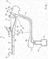
- FIG. 1 A first embodiment will be described with reference to FIG. 1 , FIG. 2A , FIG. 2B , FIG. 3A , FIG. 3B and FIG. 3C .
- depiction of some members is omitted for the purpose of clearer illustration, for example, like the omission of depiction of a cylinder 71 and a piston 73 in FIG. 1 .
- Endoscope 10
- An endoscope 10 as illustrated in FIG. 1 is, for example, a side-viewing endoscope, and functions as an insertion device.
- the endoscope 10 includes a hollow, elongated insertion section 20 which is inserted in a lumen such as a body cavity of a patient, and an operation section 30 which is coupled to a proximal end portion of the insertion section 20 and operates the endoscope 10.
- the insertion section 20 includes a distal rigid portion 21, a bendable portion 23 and a flexible tube portion 25, successively in the order from a distal end portion side of the insertion section 20 toward the proximal end portion side of the insertion section 20.
- a proximal end portion of the distal rigid portion 21 is coupled to a distal end portion of the bendable portion 23, and a proximal end portion of the bendable portion 23 is coupled to a distal end portion of the flexible tube portion 25.
- the bendable portion 23 bends in a desired direction, such as an upward, downward, right or left direction, by an operation of a bending operation unit (not shown). By the bending of the bendable portion 23, a position and direction of the distal rigid portion 21 vary.
- illumination light is radiated on an observation target, and the observation target is captured within an observation view field.
- the observation target is, for example, an affected part and a diseased part in a subject (e.g. body cavity).
- the flexible tube portion 25 has desired flexibility. Thus, the flexible tube portion 25 is bent by external force.
- the flexible tube portion 25 is a tubular member extending from a body portion 31 (to be described later) of the operation section 30.
- the operation section 30 includes the body portion 31 from which the flexible tube portion 25 extends; a grasping portion 33 which is coupled to a proximal end portion of the body portion 31 and is grasped by an operator who operates the endoscope 10; and a universal cord 41 which is connected to the grasping portion 33.
- the grasping portion 33 includes a treatment instrument insertion portion 35, a bending operation section (not shown) which bend-operates the bendable portion 23, and a switch section 39.
- the treatment instrument insertion portion 35 is disposed on a distal end portion side of the grasping portion 33.
- the bending operation section and the switch section 39 are disposed on a proximal end portion side of the grasping portion 33.
- the treatment instrument insertion portion 35 is branched from the grasping portion 33.
- a center axis direction of the treatment instrument insertion portion 35 is inclined to a center axis direction of the grasping portion 33.
- the treatment instrument insertion portion 35 includes a treatment instrument insertion hole portion 35a which is disposed at an end portion of the treatment instrument insertion portion 35 and is provided for inserting a guide member 300 (see FIG. 3B and FIG. 3C ) and a treatment instrument 400 (see FIG. 3C ), which will be described later, into the endoscope 10.
- the treatment instrument insertion hole portion 35a is coupled to a proximal end portion of a treatment instrument insertion channel which functions also as an insertion section-side conduit portion 61a of a first suction conduit portion 61 to be described later.
- the treatment instrument insertion channel is disposed in the inside of the insertion section 20, and is provided from the flexible tube portion 25 to the distal rigid portion 21 via the bendable portion 23.
- a distal end portion of the treatment instrument insertion channel communicates with a distal opening portion 35c which is provided in an outer peripheral surface of the distal rigid portion 21.
- the treatment instrument insertion hole portion 35a is an insertion hole portion for inserting the guide member 300 and treatment instrument 400 into the treatment instrument insertion channel.
- a center axis of the treatment instrument insertion hole portion 35a is disposed coaxial with the center axis of the treatment instrument insertion portion 35, and is thus inclined to the center axis of the grasping portion 33. Furthermore, the center axis direction is inclined to the center axis direction of the grasping portion 33.
- the treatment instrument insertion portion 35 further includes a cylindrical forceps plug portion 36 which is detachably provided on the treatment instrument insertion hole portion 35a.
- a center axis of the forceps plug portion 36 is disposed coaxial with the center axis of the treatment instrument insertion hole portion 35a.
- the forceps plug portion 36 is inclined to the grasping portion 33.
- the forceps plug portion 36 has such flexibility as to become openable/closable.
- This forceps plug portion 36 is formed of, for example, a resin such as rubber.
- the forceps plug portion 36 is disposed on the treatment instrument insertion hole portion 35a, and when the treatment instrument 400 is not inserted into the treatment instrument insertion channel via the forceps plug portion 36, the forceps plug portion 36 is closed and the treatment instrument insertion hole portion 35a is closed by the forceps plug portion 36.
- the forceps plug portion 36 is closed and the forceps plug portion 36 comes in close contact with the treatment instrument 400.
- the guide member 300 illustrated in FIG. 3B and FIG. 3C and the treatment instrument 400 illustrated in FIG. 3C are inserted into the treatment instrument insertion channel from the forceps plug portion 36 and are pushed in up to the distal rigid portion 21 side.
- the guide member 300 and treatment instrument 400 are projected from the distal opening portion 35c.
- the switch section 39 includes a suction switch 39a, an air/water feed switch 39b, and various switches 39c for endoscopic imaging.
- the suction switch 39a, air/water feed switch 39b and various switches 39c are operated by the operator's hand when the grasping portion 33 is held by the operator.
- the suction switch 39a is operated when the endoscope 10 sucks fluids, such as a body fluid including mucus and contaminated fluid in a lumen, from the distal opening portion 35c, which serves also as a suction opening portion, via a suction conduit portion 60 to be described later, or in other words, the suction switch 39a is operated in a suction state to be described later.
- fluids such as a body fluid including mucus and contaminated fluid in a lumen
- the air/water feed switch 39b is a part of an air/water feed mechanism (not shown). Since the structure of the air/water feed mechanism is publicly known, a detailed description thereof is omitted here.
- the universal cord 41 extends from a side surface of the grasping portion 33.
- the universal cord 41 includes a connection portion 41a which is connected to a suction device 14a.
- the suction device 14a includes, for example, a suction pump (not shown), and a suction bottle 14b.
- the endoscope 10 includes a suction mechanism 50 which is connected to the suction device 14a when the connection portion 41a is connected to the suction device 14a, and which sucks fluids by suction force of the suction pump of the suction device 14a.
- the fluids include liquids as such as a body fluid including mucus and contaminated fluid in a lumen.
- Such a fluid is stored in the suction bottle 14b.
- the suction mechanism 50 includes a suction conduit portion 60, which includes the distal opening portion 35c serving also as the suction opening portion, and the treatment instrument insertion hole portion 35a; and a fluid plug unit 70 which is connected to the suction conduit portion 60 so as to communicate with the suction conduit portion 60, and which functions as a suction valve unit that is used for suction.
- the suction conduit portion 60 includes a first suction conduit portion 61 including the treatment instrument insertion hole portion 35a, on which the forceps plug portion 36 is provided, and the distal opening portion 35c; and a second suction conduit portion 63 which is connected to the suction device 14a.
- the distal opening portion 35c sucks the fluid, and the guide member 300 and treatment instrument 400 project from the distal opening portion 35c.
- Each of the first suction conduit portion (first conduit) 61 and second suction conduit portion (second conduit) 63 has a cylindrical shape, for example, a circular cylindrical shape.
- the first suction conduit portion 61 and second suction conduit portion 63 are formed of, for example, flexible tubes of a resin material or the like.
- the first suction conduit portion 61 includes a distal end and a proximal end, and passes a fluid between the distal end and the proximal end.
- the first suction conduit portion 61 includes a distal end portion which is provided at the distal end portion of the insertion section 20, and two-forked proximal end portions which are provided on the proximal end side of the insertion section 20.
- This first suction conduit portion 61 includes the insertion section-side conduit portion 61a which is provided in the inside of the insertion section 20 and body portion 31; and an operation section-side conduit portion 61b which is provided in the inside of the body portion 31 and grasping portion 33.
- the insertion section-side conduit portion 61a functions as the treatment instrument insertion channel which is provided from the distal opening portion 35c (suction opening portion) to the treatment instrument insertion hole portion 35a.
- the treatment instrument insertion hole portion 35a functions as one of the proximal end portions of the first suction conduit portion 61.
- the insertion section-side conduit portion 61a communicates with the distal opening portion 35c and treatment instrument insertion hole portion 35a.
- the operation section-side conduit portion 61b is provided from a two-forked portion 62 of the first suction conduit portion 61, which is coupled to the insertion section-side conduit portion 61a, to the fluid plug unit 70.
- the fluid plug unit 70 functions as the other proximal end portion of the first suction conduit portion 61.
- the operation section-side conduit portion 61b communicates with the insertion section-side conduit portion 61a at the two-forked portion 62, and communicates with the fluid plug unit 70 at a proximal end portion of the operation section-side conduit portion 61b.
- the first suction conduit portion 61 is connected to, and communicates with, the distal opening portion 35c, the treatment instrument insertion hole portion 35a on which the forceps plug portion 36 is provided, and the fluid plug unit 70.
- the first suction conduit portion 61 includes a distal conduit portion 62a which is coupled to the distal opening portion 35c, a first proximal conduit portion 62b which is coupled to the treatment instrument insertion hole portion 35a, and a second proximal conduit portion 62c which is coupled to the fluid plug unit 70.
- the distal conduit portion 62a, first proximal conduit portion 62b and second proximal conduit portion 62c communicate with, and are connected to, each other at the two-forked portion 62.
- the distal conduit portion 62a and first proximal conduit portion 62b function as the first suction conduit portion 61
- the second proximal conduit portion 62c function as the operation section-side conduit portion 61b.
- the first suction conduit portion 61 includes the forceps plug portion 36 into which the treatment instrument 400 is inserted, and the distal opening portion 35c from which the treatment instrument 400 projects and which sucks a fluid.
- the second suction conduit portion 63 is provided from the fluid plug unit 70 to the connection portion 41a via the universal cord 41.
- a distal end portion of the second suction conduit portion 63 communicates with the fluid plug unit 70.
- a proximal end portion of the second suction conduit portion 63 communicates with the suction device 14a when the connection portion 41a is connected to the suction device 14a.
- the second suction conduit portion 63 is provided in the inside of the grasping portion 33 and universal cord 41.
- the second suction conduit portion 63 is connected to the suction device 14a, and passes a fluid.
- the first suction conduit portion 61 sucks, by the suction force of the suction device 14a, a fluid by passing the fluid from the distal opening portion 35c, which is the distal end portion of the first suction conduit portion 61, to the fluid plug unit 70 via the two-forked portion 62, the fluid plug unit 70 being provided at the proximal end portion of the first suction conduit portion 61.
- the fluid flows from the distal conduit portion 62a through the second proximal conduit portion 62c via the two-forked portion 62, and is sucked into the fluid plug unit 70.
- the second suction conduit portion 63 sucks, by the suction force of the suction device 14a, the fluid by passing the fluid from the fluid plug unit 70, which is provided at the distal end portion of the second suction conduit portion 63, to the suction device 14a which is provided at the proximal end portion of the second suction conduit portion 63.
- the fluid flows from the fluid plug unit 70 through the second suction conduit portion 63, and is sucked into the suction device 14a.
- the fluid plug unit 70 is provided in the grasping portion 33. As described above, the fluid plug unit 70 is connected to the first suction conduit portion 61 and second suction conduit portion 63, and communicates with the first suction conduit portion 61 and second suction conduit portion 63.
- the fluid plug unit 70 includes a cylinder 71 which is connected to the first suction conduit portion 61 and second suction conduit portion 63 such that the first suction conduit portion 61 and second suction conduit portion 63 communicate each other; and the suction switch 39a including a pushing portion 391b and a piston 73.
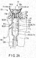
- the pushing portion 391b is an operation portion which is operated in order to switch one of a leakage suppression state (a first position, a release position, an auto-suction state; see FIG. 2A ) and the suction state (a second position, a pushed position, a pushed state; see FIG. 2B ) to the other, for example, when the insertion section 20 is inserted in a lumen.
- This switching is implemented by the movement of the piston 73 relative to the cylinder 71.
- a pressure on the distal opening portion 35c side refers to, for example, the pressure in the lumen into which the distal end side of the insertion section 20 is inserted.
- the suction state is a state in which, regardless of whether the pressure on the distal opening portion 35c side is higher than the outside air pressure on the forceps plug portion 36 side, the fluid is sucked from the distal opening portion 35c by the suction device 14a, and the fluid is forcibly sucked by the suction device 14a via the first suction conduit portion 61 and second suction conduit portion 63.
- the suction in the leakage suppression state is implemented by the suction of the suction device 14a in substantially the same manner as in the suction state.
- the fluid is sucked from the distal opening portion 35c by the suction device 14a, flows through the first suction conduit portion 61, fluid plug unit 70 and second suction conduit portion 63, and is stored in the suction bottle 14b.
- the cylinder 71 communicates with the first suction conduit portion 61 and second suction conduit portion 63, such that the first suction conduit portion 61 and second suction conduit portion 63 communicate with each other.
- the piston 73 is detachably fittingly inserted in this cylinder 71, and is movable in the axial direction of the cylinder 71 relative to the cylinder 71 in accordance with an operation of the pushing portion 391b.
- the fluid plug unit 70 switches one of the leakage suppression state illustrated in FIG. 2A and the suction state illustrated in FIG. 2B to the other, by moving the piston 73 relative to the cylinder 71 in accordance with a pushing operation or a releasing operation (non-operation) of the pushing portion 391b.
- the piston 73 moves upward by an urging member 77 (to be described later), and the fluid plug unit 70 is switched from the suction state to the leakage suppression state.
- the pushing portion 391b is push-operated and the piston 73 is pushed inside the grasping portion 33 in a axial direction of the piston 73, the fluid plug unit 70 is switched from the leakage suppression state to the suction state.
- the fluid plug unit 70 switches one of the leakage suppression state illustrated in FIG. 2A and the suction state illustrated in FIG. 2B to the other.
- the piston 73 being fittingly inserted into the cylinder 71 and moving in the axial direction of the cylinder 71, the piston 73 switches one of a first position where the fluid in the first suction conduit portion 61 that is the first conduit is suppressed from leaking to the outside from the forceps plug portion 36, and a second position where the fluid is sucked by the suction device 14a via the first conduit and the second suction conduit portion 63 that is the second conduit, to the other.
- the cylinder 71 has, for example, a cylindrical shape having a center axis C.
- the cylinder 71 is formed of, for example, a metallic material such as stainless steel.
- the cylinder 71 includes one end portion 71a which opens such that the piston 73 is fittingly inserted into the cylinder 71, and the other end portion 71b which opens, and to which the second suction conduit portion 63 is connected such that the second suction conduit portion 63 communicates with the cylinder 71.
- the one end portion 71a functions as an insertion hole portion through which the piston 73 is fittingly inserted into the cylinder 71.
- the cylinder 71 further includes a side-surface opening portion 71c to which the first suction conduit portion 61 is connected such that the first suction conduit portion 61 communicates with the cylinder 71.
- the cylinder 71 is insertable/drawable into/from a hole portion 33a which is provided in the grasping portion 33, the one end portion 71a of the cylinder 71 is fixed to the grasping portion 33, and the other end portion 71b of the cylinder 71 is disposed within the grasping portion 33.
- An O-ring (not shown) or the like is provided at the one end portion 71a of this cylinder 71.
- the piston 73 has a cylindrical shape which is elongated in the axial direction of the piston 73.
- the piston 73 is formed of a material with chemical resistance.
- This piston 73 is formed of, for example, at least one of polypropylene, polycarbonate, nylon, a sulfone-based resin such as polysulfone or polyphenylsulfone, a liquid crystal polymer, denatured polyphenylene ether, and polyether ether ketone.
- the piston 73 includes one end portion which is disposed on the outside of the cylinder 71 (grasping portion 33) and is, for example, screw-engaged with the plate-shaped pushing portion 391b, and the other end portion (opening end portion) disposed in the inside of the cylinder 71.
- the outside diameter of the piston 73 is substantially equal to the inside diameter of the cylinder 71 such that the piston 73 secures a liquid-tight state with the cylinder 71.
- the outer peripheral surface of the piston 73 slides on the inner peripheral surface of the cylinder 71.
- the piston 73 includes the vent hole portion 73a which is provided on the one end portion side, and takes outside air into the inside of the piston 73.
- the piston 73 is attached to an attachment portion 75 disposed on the one end portion side of the piston 73.
- the attachment portion 75 is disposed such that the piston 73 is inserted through the attachment portion 75 and the attachment portion 75 surrounds the one end portion side of the piston 73.
- the attachment portion 75 has a cylindrical shape with a bottom surface 75a on one side.
- the bottom surface 75a has an insertion hole 75b for insertion of the piston 73.
- the bottom surface 75a abuts on a flange portion 33c which is provided at a periphery of the hole portion 33a. In the axial direction of the piston 73, the bottom surface 75a is provided under the pushing portion 391b.
- the attachment portion 75 is formed of, for example, a soft material such as rubber.
- the urging member 77 of the suction switch 39a is disposed between the bottom surface 75a and pushing portion 391b, and abuts on the bottom surface 75a and pushing portion 391b, in the axial direction of the piston 73.
- the urging member 77 is disposed such that the urging member 77 is wound around the piston 73 that is exposed from the cylinder 71.
- a metallic coil spring is used as the urging member 77.
- the urging member 77 is expandable/contractible in the axial direction of the piston 73.
- the urging member 77 has such urging force as to urge the pushing portion 391b upward in FIG.
- the pushing portion 391b, piston 73, attachment portion 75 and urging member 77 are integrally formed as one body.
- the suction switch 39a can be attached/detached, as one unit, to/from the flange portion 33c by the attachment portion 75.
- the piston 73 according to this embodiment is positioned in a circumferential direction.
- the piston 73 is positioned in the circumferential direction, by the attachment portion 75 and flange portion 33c being properly formed.
- the suction mechanism 50 includes a leakage suppression passage portion 80 which is a first passage, and a suction passage portion 90 which is a second passage.
- the leakage suppression passage portion 80 includes a leakage suppression through-hole 81 which is provided such that the leakage suppression through-hole 81 penetrates a peripheral surface of the piston 73, and communicates with the first suction conduit portion 61 in the leakage suppression state.
- the leakage suppression passage portion 80 further includes an internal space of the piston 73 (hereinafter referred to as "piston internal space portion 731”) which communicates with the leakage suppression through-hole 81, and an internal space of the cylinder 71 (hereinafter referred to as "cylinder internal space portion 711”) which communicates with the piston internal space portion 731.
- the leakage suppression through-hole 81 has, for example, a circular shape.
- the leakage suppression passage portion 80 establishes communication between the first suction conduit portion 61 and second suction conduit portion 63 in the leakage suppression state illustrated in FIG. 2A , and permits suction.
- a fluid is passed through the leakage suppression passage portion 80.
- the leakage suppression passage portion 80 which is the first passage, communicates with the first suction conduit portion 61 which is the first conduit, and the second suction conduit portion 63 which is the second conduit, when the piston 73 is disposed in the first position that is the leakage suppression state illustrated in FIG. 2A .
- the leakage suppression passage portion 80 does not communicate with the first suction conduit portion 61 in the suction state illustrated in FIG. 2B , that is, the leakage suppression passage portion 80 is shut off from the first suction conduit portion 61, but the leakage suppression passage portion 80 keeps the state of communication with the second suction conduit portion 63.
- the leakage suppression passage portion 80 is set in the state in which the leakage suppression passage portion 80 does not suck.
- the leakage suppression passage portion 80 that is the first passage shuts off communication with the first suction conduit portion 61 that is the first conduit.
- the suction passage portion 90 includes a suction through-hole 91 which is provided such that the suction through-hole 91 penetrates the peripheral surface of the piston 73, and communicates with the first suction conduit portion 61 in the suction state.
- the suction passage portion 90 further includes the above-described piston internal space portion 731 which also communicates with the suction through-hole 91, and the above-described cylinder internal space portion 711. It is preferable that the suction through-hole 91 has, for example, a circular shape.
- the suction passage portion 90 does not communicate with the first suction conduit portion 61 in the leakage suppression state illustrated in FIG. 2A , that is, the suction passage portion 90 is shut off from the first suction conduit portion 61, but the suction passage portion 90 communicates with the second suction conduit portion 63.
- the suction passage portion 90 is set in the state in which the suction passage portion 90 does not suck.
- the suction passage portion 90 communicates with the first suction conduit portion 61 and second suction conduit portion 63 in order to permit suction in the suction state illustrated in FIG. 2B , and permits suction of a fluid.
- the suction passage portion 90 in the suction state illustrated in FIG. 2B , the fluid is passed through the suction passage portion 90.
- the suction passage portion 90 which is the second passage, shuts off communication with the first suction conduit portion 61 which is the first conduit, when the piston 73 is disposed in the first position that is the leakage suppression state illustrated in FIG. 2A , and the suction passage portion 90 communicates with the first suction conduit portion 61 which is the first conduit, and the second suction conduit portion 63 which is the second conduit, and permits suction of the fluid, when the piston 73 is disposed in the second position that is the suction state illustrated in FIG. 2B .
- the leakage suppression through-hole 81 and suction through-hole 91 are disposed coaxial with each other.
- the leakage suppression through-hole 81 is disposed at a greater distance from the pushing portion 391b than the suction through-hole 91 in the axial direction of the piston 73.
- the piston internal space portion 731 and cylinder internal space portion 711 serve also as the leakage suppression passage portion 80 and suction passage portion 90, are shared by the leakage suppression passage portion 80 and suction passage portion 90, and are used in each of the leakage suppression state and suction state.
- the leakage suppression passage portion 80 and suction passage portion 90 always communicate with the second suction conduit portion 63, regardless of the movement of the piston 73, or in other words, in each of the leakage suppression state and suction state.
- the piston 73 keeps the state in which the piston 73 is moved upward by the urging force of the urging member 77.
- the fluid plug unit 70 enters the leakage suppression state, the leakage suppression passage portion 80 communicates with the first suction conduit portion 61, and the suction passage portion 90 does not communicate with the first suction conduit portion 61.
- the leakage suppression passage portion 80 establishes communication between the first suction conduit portion 61 and second suction conduit portions 63 in order to perform suction in the leakage suppression state. In other words, in the leakage suppression state, the leakage suppression passage portion 80 establishes communication between the distal opening portion 35c side and the suction device 14a side.
- the piston 73 is moved downward by the pushing portion 391b.
- the fluid plug unit 70 is switched from the leakage suppression state to the suction state, the leakage suppression passage portion 80 does not communicate with the first suction conduit portion 61, that is, the leakage suppression passage portion 80 is shut off from the first suction conduit portion 61, and the suction passage portion 90 communicates with the first suction conduit portion 61.
- the suction passage portion 90 establishes communication between the first suction conduit portion 61 and second suction conduit portions 63 in order to perform suction in the suction state. In other words, in the suction state, the suction passage portion 90 establishes communication between the distal opening portion 35c side and the suction device 14a side.
- the leakage suppression passage portion 80 that is the first passage at a time when the piston 73 is disposed in the first position that is the leakage suppression state illustrated in FIG. 2A , has such a structure that the fluid flows less easily in the state in which the fluid is sucked by the suction device 14a, compared to the suction passage portion 90 that is the second passage at a time when the piston 73 is disposed in the second position that is the suction state illustrated in FIG. 2B .
- an amount of opening of the leakage suppression passage portion 80 is smaller than an amount of opening of the suction passage portion 90.
- a diameter of the leakage suppression through-hole 81 is less than a diameter of the suction through-hole 91.
- the amount of opening of the leakage suppression passage portion 80 is smaller than an amount of opening of a communication portion 61c of the first suction conduit portion 61 which communicates with the leakage suppression passage portion 80.
- the communication portion 61c of the first suction conduit portion 61 in relation to the cylinder 71 has, for example, a circular shape.
- a diameter of the leakage suppression through-hole 81 is less than a diameter of the communication portion 61c of the first suction conduit portion 61 which communicates with the leakage suppression passage portion 80.
- the resistance of the leakage suppression passage portion 80 which indicates the difficulty of flow of the fluid in the leakage suppression passage portion 80
- the resistance of the leakage suppression passage portion 80 is greater than the resistance of the suction passage portion 90, which indicates the difficulty of flow of the fluid in the suction passage portion 90.
- the fluid in the leakage suppression passage portion 80 in the leakage suppression state in the state in which the fluid is sucked by the suction device 14a flows less easily than the fluid in the suction passage portion 90 in the suction state in the state in which the fluid is sucked by the suction device 14a.
- the diameter of the suction through-hole 91 is identical to the diameter of the communication portion 61c, or is greater than the diameter of the communication portion 61c.
- the suction device 14a is always driven in the leakage suppression state and in the suction state, and suction is performed, for example, in each of the leakage suppression state and the suction state.
- suction in the leakage suppression state, suction is performed in order to suppress the fluid from leaking to the outside from the forceps plug portion 36.
- suction in the suction state, suction is performed in order to cause the fluid to be sucked into the suction device 14a.
- the fluid is sucked by the suction force of the suction device 14a from the distal opening portion 35c into the first suction conduit portion 61.
- the sucked fluid flows, by the suction force, from the first suction conduit portion 61 to the suction device 14a via the fluid plug unit 70 and second suction conduit portion 63, and is sucked into the suction device 14a.
- the suction device 14a When the endoscope 10 is used, the suction device 14a is always driven, and continues to exhibit a suction function. As illustrated in FIG. 2A , when the pushing portion 391b is non-operated (is released), the leakage suppression through-hole 81 with the diameter, which is less than the diameter of the suction through-hole 91, communicates with the first suction conduit portion 61. Thereby, the leakage suppression state is kept in the fluid plug unit 70.
- the insertion section 20 is inserted in a lumen as desired. It is assumed that in the leakage suppression state, the pressure on the distal opening portion 35c side in the lumen has become gradually higher than the outside air pressure on the forceps plug portion 36 side on the outside of the lumen. Then, the pressure in the distal conduit portion 62a becomes gradually higher than the pressure in the first proximal conduit portion 62b. In addition, the pressure in the distal conduit portion 62a becomes gradually higher than the pressure in the second proximal conduit portion 62c. In the leakage suppression state, the suction force of the suction device 14a always acts in the cylinder internal space portion 711.
- the pressure in the second proximal conduit portion 62c becomes gradually lower than the pressure in the first proximal conduit portion 62b by an action of the suction force.
- the fluid flows more easily from the distal conduit portion 62a to the second proximal conduit portion 62c via the two-forked portion 62, than from the distal conduit portion 62a to the first proximal conduit portion 62b via the two-forked portion 62, and flows the fluid plug unit 70. Furthermore, in the fluid plug unit 70, the fluid flows into the second suction conduit portion 63 which communicates with the cylinder 71, via the leakage suppression through-hole 81 communicating with the second proximal conduit portion 62c, the piston internal space portion 731 and the cylinder internal space portion 711. Then, the fluid continues to be sucked into the suction bottle 14a through the second suction conduit portion 63 by the suction of the suction device 14a.
- the fluid is prevented from being discharged from the forceps plug portion 36 through the first proximal conduit portion 62b by the pressure difference.
- the piston 73 moves downward relative to the cylinder 71, the communication between the first suction conduit portion 61 and the leakage suppression through-hole 81 is shut off, and the suction through-hole 91 with the diameter which is greater than the diameter of the leakage suppression through-hole 81, communicates with the first suction conduit portion 61.
- the fluid plug unit 70 is switched to the suction state.
- the fluid flows from the distal conduit portion 62a via the two-forked portion 62 to the fluid plug unit 70 through the second proximal conduit portion 62c.
- the fluid flows into the second suction conduit portion 63 which communicates with the cylinder 71, via the suction through-hole 91 communicating with the second proximal conduit portion 62c, the piston internal space portion 731 and the cylinder internal space portion 711. Then, the fluid continues to be sucked in the suction bottle 14b through the second suction conduit portion 63.
- the resistance of the leakage suppression passage portion 80 which indicates the difficulty of flow of the fluid in the leakage suppression passage portion 80, is greater than the resistance of the suction passage portion 90, which indicates the difficulty of flow of the fluid in the suction passage portion 90.
- the leakage suppression passage portion 80 includes the leakage suppression through-hole 81, and the suction passage portion 90 includes the suction through-hole 91. Thereby, the above can be implemented with a simple configuration.
- the leakage suppression through-hole 81 is disposed coaxial with the suction through-hole 91. Thereby, by the pushing portion 391b simply pushing or releasing the piston 73, one of the leakage suppression state and the suction state is easily switched to the other.
- the side-viewing endoscope 10 is used for, for example, endoscopic retrograde cholangiopancreatography (hereinafter referred to as "ERCP").
- ERCP endoscopic retrograde cholangiopancreatography
- ERCP is an operation method in which, as illustrated in FIG. 3A, FIG. 3B and FIG. 3C , a contrast medium is injected in a lumen such as a bile duct 101, and a biliary tract system and a pancreatic duct, which are affected parts in the lumen, are photographed and examined, and the affected parts are treated by the treatment instrument 400.
- the treatment instrument 400 is guided to the affected part by the guide member 300
- the guide member 300 is formed of, for example, a fine line-shaped member.
- the line-shaped member includes, for example, a stainless-steel wire.
- the line-shaped member may include, for example, a nickel-titanium wire having a surface coated with, for example, a fluororesin.
- the treatment instrument 400 includes, for example, a knife for endoscopic sphincterotomy (hereinafter referred to as "EST"), a cannula, a guide wire, a scissors-like treatment instrument, a tweezers-like treatment instrument, a forceps, a basket-like treatment instrument for breaking a stone, and a basket-like treatment instrument for taking a stone out of the body without breaking the stone.
- the treatment instrument 400 is formed of, for example, a fine line-shaped member.
- the treatment instrument 400 includes an insertion hole portion (not shown) through which the guide member 300 as illustrated in FIG. 3C can be inserted.
- the treatment instruction 400 can slide on the guide member 300 so that the guide member 300 may be inserted through the insertion hole portion. By this sliding, the treatment instrument 400 can move along the guide member 300.
- the insertion section 20 is inserted in a lumen such as the duodenum 100, and a contrast tube 600 called “cannula” is inserted into the bile duct 101 from the forceps plug portion 36 via the treatment instrument insertion channel (insertion section-side conduit portion 61a) and the distal opening portion 35c.
- a contrast medium is injected in a subject such as the bile duct 101 via the contrast tube 600, and the subject such as the bile duct 101 is photographed by roentgen photography or the like.
- the guide member 300 is inserted into the contrast tube 600, and a distal end portion of the guide member 300 projects from a distal end of the contrast tube 600. Then, the distal end portion of the guide member 300 reaches the subject such as the bile duct 101. In the meantime, a proximal end portion of the guide member 300 is exposed to the outside of the endoscope 10 from the forceps plug portion 36. Then, in the state in which the guide member 300 is left in the subject such as the bile duct 101, only the contrast tube 600 is pulled out of the endoscope 10.
- the treatment instrument 400 moves along the guide member 300, the treatment instrument 400 is guided by the guide member 300, and is inserted into the treatment instrument insertion channel from the forceps plug portion 36. Then, in the state in which the treatment instrument 400 is guided by the guide member 300, the treatment instrument 400 projects to the lateral side from the distal opening portion 35c, and reaches the subject.
- the treatment instrument 400 is guided by the guide member 300 up to the subject, and treats the affected part.
- the pressure inside the duodenum 100 in which the insertion section 20 was inserted becomes higher than, for example, the outside air pressure at the forceps plug portion 36.
- the pressure in the lumen in which the insertion section 20 was inserted becomes higher than, for example, the outside air pressure at the forceps plug portion 36.
- the fluid remaining in the suction conduit portion 60 includes, for example, a fluid remaining in the insertion section-side conduit portion 61a that is the treatment instrument insertion channel by the use of the treatment instrument 400, and a fluid which was not sucked by the suction device 14a when the fluid was sucked into the endoscope 10, and remains in the operation section-side conduit portion 61b and the second suction conduit portion 63.
- the suction device 14a is always driven even in a state during treatment, a treatment instrument replacement state, an observation state and the leakage suppression state including a non-operation (released) state, as illustrated in FIG. 2A , the leakage suppression conduit portion 80 establishes communication between the first suction conduit portion 61 and second suction conduit portion 63 in the leakage suppression state. In other words, the leakage suppression conduit portion 80 establishes communication between the distal opening portion 35c side and the suction device 14a side.
- the suction force always acts in the leakage suppression conduit portion 80, first suction conduit portion 61 and second suction conduit portion 63. In other words, the suction force acts up to the distal opening portion 35c side.
- the fluid remaining in the first suction conduit portion 61, second suction conduit portion 63 and fluid plug unit 70 is affected by the suction force by the above-described communication, if not in the suction state.
- the fluid is exactly sucked, for example, by the suction device 14a.
- the present embodiment even if the pressure in the lumen such as the duodenum 100 becomes higher than the outside air pressure, it is possible to suppress a fluid from leaking from the forceps plug portion 36. In this embodiment, while the leakage of fluid from the forceps plug portion 36 is suppressed, it is possible to prevent the degradation of insertion-removal properties of the treatment instrument 400 to the forceps plug portion 36.
- the suction device 14a is always driven in the leakage suppression state and in the suction state, the suction force is fixed and equal, for example, between the leakage suppression state and the suction state.
- this suction force acts, for example, on the affected part in the subject and on the fluid such as a body fluid, via the suction mechanism 50 and distal opening portion 35c.
- the leakage suppression state includes the state during treatment, in which the affected part is being treated by the treatment instrument 400, the replacement state in which the treatment instrument 400 is replaced, the observation state in which the affected part is observed, and the non-operation state (released state) in which the suction switch 39a is not operated.
- the suction force in the leakage suppression state would act on the affected part via the suction mechanism 50 and distal opening portion 35c.
- the affected part would be pulled into the distal opening portion 35c as in the suction state by the action force, such as suction force, which acts on the affected part as in the suction state.
- the leakage suppression state including the state during treatment and the observation state, if the affected part is pulled into the the distal opening portion 35c as in the suction state, there is concern that problems occur with the treatment and observation.
- the resistance of the leakage suppression passage portion 80 is higher than the resistance of the suction passage portion 90.
- the amount of opening of the leakage suppression passage portion 80 is smaller than the amount of opening of the suction passage portion 90, or the amount of opening of the leakage suppression passage portion 80 is smaller than the amount of opening of the communication portion 61c which communicates with the leakage suppression passage portion 80.
- the leakage suppression passage portion 80 includes the leakage suppression through-hole 81
- the suction passage portion 90 includes the suction through-hole 91.
- the leakage suppression through-hole 81 is disposed coaxial with the suction through-hole 91. Thereby, in this embodiment, one of the leakage suppression state and the suction state can easily be switched to the other.
- the suction force is fixed and equal between the leakage suppression state and the suction state.
- the suction force may be adjusted as desired in accordance with the leakage suppression state and the suction state.
- the first suction conduit portion 61 may include a filter member, such as a filter, for filtering the fluid, thereby to prevent clogging of the leakage suppression through-hole 81 due to the fluid.
- a filter member such as a filter
- the leakage suppression through-hole 81 is larger than the fluid to be sucked.
- the suction mechanism 50 may be disposed in a direct-viewing endoscope 10.
- the pressure on the distal opening portion 35c side e.g. the pressure in the large intestine in which the distal end side of the insertion section 20 is inserted
- the pressure on the distal opening portion 35c side becomes higher than the outside air pressure on the forceps plug portion 36 side.
- the above-described fluid plug unit 70 can suppress such leakage.
- FIG. 4A and FIG. 4B a first modification of the present embodiment is described.
- the present modification only different points from the first embodiment are described.
- the leakage suppression passage portion 80 further includes a valve 83 which is provided on a peripheral surface of the piston 73 in a manner to communicate with the first suction conduit portion 61 in the leakage suppression state.
- the valve 83 opens in the leakage suppression state. Specifically, the valve 83 opens if the pressure on the distal opening portion 35c side becomes higher than the outside air pressure on the forceps plug portion 36 side.
- the pressure on the distal opening portion 35c side refers to, for example, the pressure in the large intestine into which the distal end side of the insertion section 20 is inserted.
- the piston 73 of the present modification is formed of, for example, a high-resiliency member of rubber or the like.
- the valve 83 includes a slit portion 83a. The valve 83 is recessed from the outer peripheral surface toward the inner peripheral surface of the piston 73 so that the valve 83 may easily open.
- the valve 83 may be formed such that the surface of the piston 73 is coated with a resin and a slit portion is provided in the resin.
- the valve 83 may be formed, for example, when the piston 73 is insert-molded.
- the valve 83 may be provided on the piston 73, for example, by double molding.
- FIG. 5A, FIG. 5B , FIG. 6A and FIG. 6B a second embodiment is described with reference to FIG. 5A, FIG. 5B , FIG. 6A and FIG. 6B .
- FIG. 5B a second embodiment is described with reference to FIG. 5A, FIG. 5B , FIG. 6A and FIG. 6B .
- FIG. 6A a second embodiment is described with reference to FIG. 5A, FIG. 5B , FIG. 6A and FIG. 6B .
- FIG. 6A and FIG. 6B only different points from the first embodiment are described.
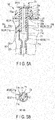
- the leakage suppression through-hole 81 is not provided, and a gap 85 is provided.
- the leakage suppression passage portion 80 includes a gap 85 which is formed between the inner peripheral surface of the cylinder 71 and the outer peripheral surface of the piston 73, and the internal space of the cylinder 71 (hereinafter referred to as "cylinder internal space portion 711") communicating with the gap 85.
- the gap 85 is formed between the inner peripheral surface of the cylinder 71 and the outer peripheral surface of the piston 73.
- the gap 85 is formed by an inner peripheral groove 71g provided in the inner peripheral surface of the cylinder 71, such that a portion 71h of the cylinder 71 is smaller in thickness than another portion 71i of the cylinder 71.
- the portion 71h neighbors the portion 71i in a circumferential direction of the cylinder 71, and is provided at the same height position as the portion 71i in the axial direction of the piston 73.
- the inner peripheral groove 71g is recessed from the inner peripheral surface of the cylinder 71 toward the outer peripheral surface of the cylinder 71.
- the inner peripheral groove 71g neighbors the side-surface opening portion 71c (first suction conduit portion 61) such that the inner peripheral groove 71g communicates with the first suction conduit portion 61 and cylinder internal space portion 711 in the leakage suppression state and in the suction state.
- the inner peripheral groove 71g is provided linearly along the axial direction of the cylinder 71.
- the inner peripheral groove 71g is provided in a part of the cylinder 71 in the circumferential direction of the cylinder 71. In this case, the piston 73 has a uniform thickness.
- the cylinder 71 may be deformed without making the portion 71h smaller in thickness than the portion 71i. Specifically, the cylinder 71 may be deformed so as to be recessed, without being reduced in thickness.
- the gap 85 may be formed by an outer peripheral groove 73g provided in the outer peripheral surface of the piston 73, such that a portion 73h of the piston 73 is smaller in thickness than another portion 73i of the piston 73.
- the portion 73h neighbors the portion 73i in the circumferential direction of the piston 73, and is provided at the same height position as the portion 73i in the axial direction of the piston 73.
- the outer peripheral groove 73g is recessed from the outer peripheral surface of the piston 73 toward the inner peripheral surface of the piston 73.
- the outer peripheral groove 73g is disposed below the suction through-hole 91, such that the outer peripheral groove 73g communicates with the first suction conduit portion 61 in the leakage suppression state, does not communicate with the first suction conduit portion 61 in the suction state, and communicates with the cylinder internal space portion 711 in the leakage suppression state and in the suction state.
- the outer peripheral groove 73g is provided linearly along the axial direction of the piston 73. In this case, the inside diameter of the cylinder 71 is uniform in the range in which the piston 73 slides.
- the piston 73 may be deformed without making the portion 73h smaller in thickness than the portion 73i. Specifically, the piston 73 may be deformed so as to be recessed, without being reduced in thickness.
- the suction force can be desirably adjusted in the leakage suppression state in accordance with the size of the gap 85.
- the fluid plug unit 70 may be provided not only in the endoscope 10, but also in various insertion devices such as a suction catheter.
Landscapes
- Health & Medical Sciences (AREA)
- Life Sciences & Earth Sciences (AREA)
- Surgery (AREA)
- Heart & Thoracic Surgery (AREA)
- General Health & Medical Sciences (AREA)
- Public Health (AREA)
- Animal Behavior & Ethology (AREA)
- Engineering & Computer Science (AREA)
- Biomedical Technology (AREA)
- Veterinary Medicine (AREA)
- Molecular Biology (AREA)
- Nuclear Medicine, Radiotherapy & Molecular Imaging (AREA)
- Medical Informatics (AREA)
- Pathology (AREA)
- Radiology & Medical Imaging (AREA)
- Physics & Mathematics (AREA)
- Optics & Photonics (AREA)
- Biophysics (AREA)
- Vascular Medicine (AREA)
- Anesthesiology (AREA)
- Hematology (AREA)
- Endoscopes (AREA)
- Instruments For Viewing The Inside Of Hollow Bodies (AREA)
- Ophthalmology & Optometry (AREA)
- External Artificial Organs (AREA)
Abstract
Description
- The present invention relates to a fluid plug unit and an insertion device.
- For example, an endoscope disclosed in, for example, Patent Literature 1 is connected, via a connection portion provided in a universal cord of the endoscope, to a suction device provided on an outside of the endoscope, in order to suck fluids such as a body fluid including mucus and contaminated fluid in a lumen. This endoscope includes a fluid plug unit which switches one of a suction state and a non-suction state to the other, by a piston being pushed relative to a cylinder.
- The endoscope further includes a suction conduit portion which includes a first suction conduit portion connected to the fluid plug unit, and a second suction conduit portion connected to the fluid plug unit.
- The first suction conduit portion includes a distal end portion which is provided at a distal end portion of an endoscope insertion section, and proximal end portions which are two-forked at a proximal end portion of the endoscope insertion section. One part of the first suction conduit portion functions as a treatment instrument insertion channel which is provided from the distal end portion of the insertion section to a treatment instrument insertion portion that functions as one of the proximal end portions. The other part of the first suction conduit portion is provided from the two-forked portion to the fluid plug unit that functions as the other proximal end portion. The other part of the first suction conduit portion communicates with the one part of the first suction conduit portion at the two-forked portion.
- The second suction conduit portion is provided from the fluid plug unit to the connection portion via the universal cord.
- Patent Literature 1: Jpn. Pat. Appln. KOKAI Publication No.
2004-201866 - For example, a side-viewing endoscope is used for endoscopic retrograde cholangiopancreatography (hereinafter referred to as "ERCP"), and an insertion section is inserted into a lumen such as the duodenum. An insertion section of a direct-viewing endoscope is inserted in a lumen such as the large intestine. When such the insertion section is inserted into the lumen, there may be a case where, in a non-suction state in which suction is not performed, a pressure in the lumen becomes higher than an outside air pressure on the side where, for example, a forceps plug portion exists.
- Owing to this relation in the pressure, there is concern that, for example, a fluid such as bile flows from a distal opening portion provided at the distal end of the insertion section into the first suction conduit portion, against the intention of the user of the endoscope. In addition, there is concern that the fluid flows into the first suction conduit portion along the treatment instrument which projects from the distal end portion of the insertion section.
- Furthermore, in some cases, when the treatment instrument is used and when the suction operation is performed, the fluid is not sucked by the suction device and may remain in one of the first suction conduit portion, the fluid plug unit and the second suction conduit portion.
- Owing to the above-described relation in pressure, there is concern that the influent fluid and the remaining fluid may leak, for example, from the forceps plug portion to the outside, when the treatment instrument is used.
- In order to suppress the leakage, it is thinkable to put the forceps plug portion in tight and close contact with the treatment instrument which is inserted through the forceps plug portion.
- However, in this case, the amount of force for inserting/removaling the treatment instrument into/from the forceps plug portion increases, and the insertion-removal properties of the treatment instrument to the forceps plug portion deteriorates.
- In this case, if the close contact between the treatment instrument and the forceps plug portion is loosened in order to replace the treatment instrument and to move advance/retreat the treatment instrument, there occurs concern that the fluid leaks to the outside from the forceps plug portion.
- As described above, there occurs concern that the fluid leaks from the forceps plug portion, depending on the condition of use of the treatment instrument and the endoscope.
- Thus, there is a demand for the suppression of leakage of a fluid from the forceps plug portion, and for the prevention of degradation of insertion-removal properties of the treatment instrument to the forceps plug portion, in the non-suction state of the endoscope.
- The present invention has been made in consideration of the above circumstance, and the object of the invention is to provide a fluid plug unit and an insertion device, which can suppress leakage of a fluid from a forceps plug portion, and can prevent degradation of insertion-removal properties of the treatment instrument to the forceps plug portion.
- An aspect according to a fluid plug unit of the invention is a fluid plug unit communicating with a first conduit including a distal end and a proximal end and configured to pass a fluid between the distal end and the proximal end, and communicating with a second conduit connected to a suction device and configured to pass the fluid, the fluid plug includes a cylinder connected to the first conduit and the second conduit such that the first conduit and the second conduit communicate with each other; a piston fittingly inserted into the cylinder and configured to move in an axial direction of the cylinder, thereby executing switching between a first position where leakage of the fluid in the first conduit to an outside is suppressed, and a second position where the fluid is sucked by the suction device via the first conduit and the second conduit; a first passage configured to communicate with the first conduit and the second conduit when the piston is disposed in the first position, and to shut off communication with the first conduit when the piston is disposed in the second position; and a second passage configured to shut off communication with the first conduit when the piston is disposed in the first position, and to communicate with the first conduit and the second conduit when the piston is disposed in the second position.
- According to the present invention, there can be provided a fluid plug unit and an insertion device, which can suppress leakage of a fluid from a forceps plug portion, and can prevent degradation of insertion-removal properties of the treatment instrument to the forceps plug portion.
-
-
FIG. 1 is a schematic view of a suction mechanism in an endoscope according to a first embodiment of the present invention. -
FIG. 2A is a view for explaining a leakage suppression state in the first embodiment. -
FIG. 2B is a view for explaining a suction state in the first embodiment. -
FIG. 3A is a view for describing a contrast tube being inserted into a bile duct. -
FIG. 3B is a view for describing a guide member being inserted into the bile duct. -
FIG. 3C is a view for describing a treatment instrument being inserted in the bile duct by being guided by the guide member. -
FIG. 4A is a front view of a valve in a first modification of the first embodiment. -
FIG. 4B is a cross-sectional view taken alongline 4B-4B inFIG. 4A . -
FIG. 5A is a view illustrating an example of a gap in a second embodiment. -
FIG. 5B is a cross-sectional view taken alongline 5B-5B inFIG. 5A . -
FIG. 6A is a view illustrating an example of the gap in the second embodiment. -
FIG. 6B is a cross-sectional view taken alongline 6B-6B inFIG. 6A . - Embodiments of the present invention will be described hereinafter in detail with reference to the accompanying drawings.
- A first embodiment will be described with reference to
FIG. 1 ,FIG. 2A ,FIG. 2B ,FIG. 3A ,FIG. 3B andFIG. 3C . Incidentally, in some of the drawings, depiction of some members is omitted for the purpose of clearer illustration, for example, like the omission of depiction of acylinder 71 and apiston 73 inFIG. 1 . [Endoscope 10] - An
endoscope 10 as illustrated inFIG. 1 is, for example, a side-viewing endoscope, and functions as an insertion device. - As illustrated in
FIG. 1 , theendoscope 10 includes a hollow,elongated insertion section 20 which is inserted in a lumen such as a body cavity of a patient, and anoperation section 30 which is coupled to a proximal end portion of theinsertion section 20 and operates theendoscope 10. - As illustrated in
FIG. 1 , theinsertion section 20 includes a distalrigid portion 21, abendable portion 23 and aflexible tube portion 25, successively in the order from a distal end portion side of theinsertion section 20 toward the proximal end portion side of theinsertion section 20. A proximal end portion of the distalrigid portion 21 is coupled to a distal end portion of thebendable portion 23, and a proximal end portion of thebendable portion 23 is coupled to a distal end portion of theflexible tube portion 25. - The
bendable portion 23 bends in a desired direction, such as an upward, downward, right or left direction, by an operation of a bending operation unit (not shown). By the bending of thebendable portion 23, a position and direction of the distalrigid portion 21 vary. In addition, illumination light is radiated on an observation target, and the observation target is captured within an observation view field. The observation target is, for example, an affected part and a diseased part in a subject (e.g. body cavity). - The
flexible tube portion 25 has desired flexibility. Thus, theflexible tube portion 25 is bent by external force. Theflexible tube portion 25 is a tubular member extending from a body portion 31 (to be described later) of theoperation section 30. - As illustrated in
FIG. 1 , theoperation section 30 includes thebody portion 31 from which theflexible tube portion 25 extends; a graspingportion 33 which is coupled to a proximal end portion of thebody portion 31 and is grasped by an operator who operates theendoscope 10; and auniversal cord 41 which is connected to the graspingportion 33. - As illustrated in
FIG. 1 , the graspingportion 33 includes a treatmentinstrument insertion portion 35, a bending operation section (not shown) which bend-operates thebendable portion 23, and aswitch section 39. The treatmentinstrument insertion portion 35 is disposed on a distal end portion side of the graspingportion 33. The bending operation section and theswitch section 39 are disposed on a proximal end portion side of the graspingportion 33. - As illustrated in
FIG. 1 , the treatmentinstrument insertion portion 35 is branched from the graspingportion 33. Thus, a center axis direction of the treatmentinstrument insertion portion 35 is inclined to a center axis direction of the graspingportion 33. - As illustrated in
FIG. 1 , the treatmentinstrument insertion portion 35 includes a treatment instrumentinsertion hole portion 35a which is disposed at an end portion of the treatmentinstrument insertion portion 35 and is provided for inserting a guide member 300 (seeFIG. 3B andFIG. 3C ) and a treatment instrument 400 (seeFIG. 3C ), which will be described later, into theendoscope 10. - The treatment instrument
insertion hole portion 35a is coupled to a proximal end portion of a treatment instrument insertion channel which functions also as an insertion section-side conduit portion 61a of a firstsuction conduit portion 61 to be described later. The treatment instrument insertion channel is disposed in the inside of theinsertion section 20, and is provided from theflexible tube portion 25 to the distalrigid portion 21 via thebendable portion 23. A distal end portion of the treatment instrument insertion channel communicates with adistal opening portion 35c which is provided in an outer peripheral surface of the distalrigid portion 21. The treatment instrumentinsertion hole portion 35a is an insertion hole portion for inserting theguide member 300 andtreatment instrument 400 into the treatment instrument insertion channel. - As illustrated in
FIG. 1 , a center axis of the treatment instrumentinsertion hole portion 35a is disposed coaxial with the center axis of the treatmentinstrument insertion portion 35, and is thus inclined to the center axis of the graspingportion 33. Furthermore, the center axis direction is inclined to the center axis direction of the graspingportion 33. - As illustrated in
FIG. 1 , the treatmentinstrument insertion portion 35 further includes a cylindricalforceps plug portion 36 which is detachably provided on the treatment instrumentinsertion hole portion 35a. A center axis of theforceps plug portion 36 is disposed coaxial with the center axis of the treatment instrumentinsertion hole portion 35a. Thus, theforceps plug portion 36 is inclined to the graspingportion 33. When theforceps plug portion 36 is disposed on the treatment instrumentinsertion hole portion 35a, theforceps plug portion 36 communicates with the treatment instrument insertion channel via the treatment instrumentinsertion hole portion 35a. - The forceps plug
portion 36 has such flexibility as to become openable/closable. Thisforceps plug portion 36 is formed of, for example, a resin such as rubber. - The forceps plug
portion 36 is disposed on the treatment instrumentinsertion hole portion 35a, and when thetreatment instrument 400 is not inserted into the treatment instrument insertion channel via theforceps plug portion 36, theforceps plug portion 36 is closed and the treatment instrumentinsertion hole portion 35a is closed by theforceps plug portion 36. When thetreatment instrument 400 is inserted into the treatment instrument insertion channel via theforceps plug portion 36, theforceps plug portion 36 is closed and theforceps plug portion 36 comes in close contact with thetreatment instrument 400. - The
guide member 300 illustrated inFIG. 3B andFIG. 3C and thetreatment instrument 400 illustrated inFIG. 3C are inserted into the treatment instrument insertion channel from theforceps plug portion 36 and are pushed in up to the distalrigid portion 21 side. In addition, as illustrated inFIG. 3B andFIG. 3C , theguide member 300 andtreatment instrument 400 are projected from thedistal opening portion 35c. - As illustrated in
FIG. 1 , theswitch section 39 includes asuction switch 39a, an air/water feed switch 39b, andvarious switches 39c for endoscopic imaging. Thesuction switch 39a, air/water feed switch 39b andvarious switches 39c are operated by the operator's hand when the graspingportion 33 is held by the operator. - The
suction switch 39a is operated when theendoscope 10 sucks fluids, such as a body fluid including mucus and contaminated fluid in a lumen, from thedistal opening portion 35c, which serves also as a suction opening portion, via asuction conduit portion 60 to be described later, or in other words, thesuction switch 39a is operated in a suction state to be described later. - The air/
water feed switch 39b is a part of an air/water feed mechanism (not shown). Since the structure of the air/water feed mechanism is publicly known, a detailed description thereof is omitted here. - As illustrated in
FIG. 1 , theuniversal cord 41 extends from a side surface of the graspingportion 33. Theuniversal cord 41 includes aconnection portion 41a which is connected to asuction device 14a. Thesuction device 14a includes, for example, a suction pump (not shown), and asuction bottle 14b. - As illustrated in
FIG. 1 , theendoscope 10 includes asuction mechanism 50 which is connected to thesuction device 14a when theconnection portion 41a is connected to thesuction device 14a, and which sucks fluids by suction force of the suction pump of thesuction device 14a. The fluids include liquids as such as a body fluid including mucus and contaminated fluid in a lumen. A solid, such as a living body tissue, which was sucked by thesuction mechanism 50, is included in the sucked fluid which moves in thesuction mechanism 50. Such a fluid is stored in thesuction bottle 14b. - As illustrated in
FIG. 1 , thesuction mechanism 50 includes asuction conduit portion 60, which includes thedistal opening portion 35c serving also as the suction opening portion, and the treatment instrumentinsertion hole portion 35a; and afluid plug unit 70 which is connected to thesuction conduit portion 60 so as to communicate with thesuction conduit portion 60, and which functions as a suction valve unit that is used for suction. - As illustrated in
FIG. 1 , thesuction conduit portion 60 includes a firstsuction conduit portion 61 including the treatment instrumentinsertion hole portion 35a, on which theforceps plug portion 36 is provided, and thedistal opening portion 35c; and a secondsuction conduit portion 63 which is connected to thesuction device 14a. Thedistal opening portion 35c sucks the fluid, and theguide member 300 andtreatment instrument 400 project from thedistal opening portion 35c. - Each of the first suction conduit portion (first conduit) 61 and second suction conduit portion (second conduit) 63, as illustrated in
FIG. 1 , has a cylindrical shape, for example, a circular cylindrical shape. The firstsuction conduit portion 61 and secondsuction conduit portion 63 are formed of, for example, flexible tubes of a resin material or the like. - As illustrated in
FIG. 1 , the firstsuction conduit portion 61 includes a distal end and a proximal end, and passes a fluid between the distal end and the proximal end. Specifically, the firstsuction conduit portion 61 includes a distal end portion which is provided at the distal end portion of theinsertion section 20, and two-forked proximal end portions which are provided on the proximal end side of theinsertion section 20. This firstsuction conduit portion 61 includes the insertion section-side conduit portion 61a which is provided in the inside of theinsertion section 20 andbody portion 31; and an operation section-side conduit portion 61b which is provided in the inside of thebody portion 31 and graspingportion 33. - The insertion section-
side conduit portion 61a functions as the treatment instrument insertion channel which is provided from thedistal opening portion 35c (suction opening portion) to the treatment instrumentinsertion hole portion 35a. The treatment instrumentinsertion hole portion 35a functions as one of the proximal end portions of the firstsuction conduit portion 61. The insertion section-side conduit portion 61a communicates with thedistal opening portion 35c and treatment instrumentinsertion hole portion 35a. - The operation section-
side conduit portion 61b is provided from a two-forkedportion 62 of the firstsuction conduit portion 61, which is coupled to the insertion section-side conduit portion 61a, to thefluid plug unit 70. Thefluid plug unit 70 functions as the other proximal end portion of the firstsuction conduit portion 61. The operation section-side conduit portion 61b communicates with the insertion section-side conduit portion 61a at the two-forkedportion 62, and communicates with thefluid plug unit 70 at a proximal end portion of the operation section-side conduit portion 61b. - In this manner, the first
suction conduit portion 61 is connected to, and communicates with, thedistal opening portion 35c, the treatment instrumentinsertion hole portion 35a on which theforceps plug portion 36 is provided, and thefluid plug unit 70. - If the above-described content is restated, the first
suction conduit portion 61 includes adistal conduit portion 62a which is coupled to thedistal opening portion 35c, a firstproximal conduit portion 62b which is coupled to the treatment instrumentinsertion hole portion 35a, and a secondproximal conduit portion 62c which is coupled to thefluid plug unit 70. Thedistal conduit portion 62a, firstproximal conduit portion 62b and secondproximal conduit portion 62c communicate with, and are connected to, each other at the two-forkedportion 62. Thedistal conduit portion 62a and firstproximal conduit portion 62b function as the firstsuction conduit portion 61, and the secondproximal conduit portion 62c function as the operation section-side conduit portion 61b. - The first
suction conduit portion 61 includes theforceps plug portion 36 into which thetreatment instrument 400 is inserted, and thedistal opening portion 35c from which thetreatment instrument 400 projects and which sucks a fluid. - As illustrated in
FIG. 1 , the secondsuction conduit portion 63 is provided from thefluid plug unit 70 to theconnection portion 41a via theuniversal cord 41. A distal end portion of the secondsuction conduit portion 63 communicates with thefluid plug unit 70. A proximal end portion of the secondsuction conduit portion 63 communicates with thesuction device 14a when theconnection portion 41a is connected to thesuction device 14a. - In this manner, the second
suction conduit portion 63 is provided in the inside of the graspingportion 33 anduniversal cord 41. In addition, the secondsuction conduit portion 63 is connected to thesuction device 14a, and passes a fluid. - In the
suction mechanism 50, when theconnection portion 41a is connected to thesuction device 14a, the firstsuction conduit portion 61 sucks, by the suction force of thesuction device 14a, a fluid by passing the fluid from thedistal opening portion 35c, which is the distal end portion of the firstsuction conduit portion 61, to thefluid plug unit 70 via the two-forkedportion 62, thefluid plug unit 70 being provided at the proximal end portion of the firstsuction conduit portion 61. Thus, the fluid flows from thedistal conduit portion 62a through the secondproximal conduit portion 62c via the two-forkedportion 62, and is sucked into thefluid plug unit 70. - The second
suction conduit portion 63 sucks, by the suction force of thesuction device 14a, the fluid by passing the fluid from thefluid plug unit 70, which is provided at the distal end portion of the secondsuction conduit portion 63, to thesuction device 14a which is provided at the proximal end portion of the secondsuction conduit portion 63. Thus, the fluid flows from thefluid plug unit 70 through the secondsuction conduit portion 63, and is sucked into thesuction device 14a. - As is illustrated in
FIG. 1 ,FIG. 2A andFIG. 2B , thefluid plug unit 70 is provided in the graspingportion 33. As described above, thefluid plug unit 70 is connected to the firstsuction conduit portion 61 and secondsuction conduit portion 63, and communicates with the firstsuction conduit portion 61 and secondsuction conduit portion 63. - As illustrated in
FIG. 2A andFIG. 2B , thefluid plug unit 70 includes acylinder 71 which is connected to the firstsuction conduit portion 61 and secondsuction conduit portion 63 such that the firstsuction conduit portion 61 and secondsuction conduit portion 63 communicate each other; and thesuction switch 39a including a pushingportion 391b and apiston 73. - As illustrated in
FIG. 1 ,FIG. 2A andFIG. 2B , the pushingportion 391b is an operation portion which is operated in order to switch one of a leakage suppression state (a first position, a release position, an auto-suction state; seeFIG. 2A ) and the suction state (a second position, a pushed position, a pushed state; seeFIG. 2B ) to the other, for example, when theinsertion section 20 is inserted in a lumen. This switching is implemented by the movement of thepiston 73 relative to thecylinder 71. A pressure on thedistal opening portion 35c side refers to, for example, the pressure in the lumen into which the distal end side of theinsertion section 20 is inserted. In the leakage suppression state, outside air is caused to flow into thecylinder 71 by thesuction device 14a, and the fluid is sucked in the secondsuction conduit portion 63. Thus, in the leakage suppression state, the fluid is suppressed from being sucked from thedistal opening portion 35c and leaking to the outside from theforceps plug portion 36 through the firstsuction conduit portion 61, as the pressure on thedistal opening portion 35c side becomes higher than the outside air pressure on theforceps plug portion 36 side. In other words, in the leakage suppression state, a fluid which has a higher pressure than the outside air pressure on thedistal opening portion 35c side, is suppressed from leaking to the outside from theforceps plug portion 36 through the firstsuction conduit portion 61. The suction state is a state in which, regardless of whether the pressure on thedistal opening portion 35c side is higher than the outside air pressure on theforceps plug portion 36 side, the fluid is sucked from thedistal opening portion 35c by thesuction device 14a, and the fluid is forcibly sucked by thesuction device 14a via the firstsuction conduit portion 61 and secondsuction conduit portion 63. - In the leakage suppression state illustrated in
FIG. 2A , in order to suppress the fluid from being discharged from theforceps plug portion 36 by a pressure difference when the pressure at thedistal opening portion 35c is higher than the outside air pressure on theforceps plug portion 36 side, the fluid is sucked into thesuction bottle 14b from the firstsuction conduit portion 61 through thefluid plug unit 70 and secondsuction conduit portion 63. In the leakage suppression state, when there is no pressure difference between the pressure at thedistal opening portion 35c and the outside air pressure on theforceps plug portion 36 side, outside air continues to be sucked from avent hole portion 73a of thepiston 73 into thesuction device 14a via an internal space of thepiston 73, an internal space of thecylinder 71 and the secondsuction conduit portion 63. Although details will be described later, the suction in the leakage suppression state is implemented by the suction of thesuction device 14a in substantially the same manner as in the suction state. - In the suction state illustrated in
FIG. 2B , the fluid is sucked from thedistal opening portion 35c by thesuction device 14a, flows through the firstsuction conduit portion 61,fluid plug unit 70 and secondsuction conduit portion 63, and is stored in thesuction bottle 14b. - As illustrated in
FIG. 2A andFIG. 2B , thecylinder 71 communicates with the firstsuction conduit portion 61 and secondsuction conduit portion 63, such that the firstsuction conduit portion 61 and secondsuction conduit portion 63 communicate with each other. Thepiston 73 is detachably fittingly inserted in thiscylinder 71, and is movable in the axial direction of thecylinder 71 relative to thecylinder 71 in accordance with an operation of the pushingportion 391b. In addition, as illustrated inFIG. 2A andFIG. 2B , thefluid plug unit 70 switches one of the leakage suppression state illustrated inFIG. 2A and the suction state illustrated inFIG. 2B to the other, by moving thepiston 73 relative to thecylinder 71 in accordance with a pushing operation or a releasing operation (non-operation) of the pushingportion 391b. - Specifically, if the operation (pushed) state of the pushing
portion 391b illustrated inFIG. 2A is switched to the non-operation (released) state, thepiston 73 moves upward by an urging member 77 (to be described later), and thefluid plug unit 70 is switched from the suction state to the leakage suppression state. As illustrated inFIG. 2B , if the pushingportion 391b is push-operated and thepiston 73 is pushed inside the graspingportion 33 in a axial direction of thepiston 73, thefluid plug unit 70 is switched from the leakage suppression state to the suction state. - In other words, by the
piston 73 moving in a axial direction of thecylinder 71 relative to thecylinder 71, thefluid plug unit 70 switches one of the leakage suppression state illustrated inFIG. 2A and the suction state illustrated inFIG. 2B to the other. Specifically, by thepiston 73 being fittingly inserted into thecylinder 71 and moving in the axial direction of thecylinder 71, thepiston 73 switches one of a first position where the fluid in the firstsuction conduit portion 61 that is the first conduit is suppressed from leaking to the outside from theforceps plug portion 36, and a second position where the fluid is sucked by thesuction device 14a via the first conduit and the secondsuction conduit portion 63 that is the second conduit, to the other. - The
cylinder 71 has, for example, a cylindrical shape having a center axis C. Thecylinder 71 is formed of, for example, a metallic material such as stainless steel. - As illustrated in
FIG. 2A andFIG. 2B , thecylinder 71 includes oneend portion 71a which opens such that thepiston 73 is fittingly inserted into thecylinder 71, and theother end portion 71b which opens, and to which the secondsuction conduit portion 63 is connected such that the secondsuction conduit portion 63 communicates with thecylinder 71. The oneend portion 71a functions as an insertion hole portion through which thepiston 73 is fittingly inserted into thecylinder 71. As illustrated inFIG. 2A andFIG. 2B , thecylinder 71 further includes a side-surface opening portion 71c to which the firstsuction conduit portion 61 is connected such that the firstsuction conduit portion 61 communicates with thecylinder 71. - As illustrated in
FIG. 2A andFIG. 2B , thecylinder 71 is insertable/drawable into/from ahole portion 33a which is provided in the graspingportion 33, the oneend portion 71a of thecylinder 71 is fixed to the graspingportion 33, and theother end portion 71b of thecylinder 71 is disposed within the graspingportion 33. An O-ring (not shown) or the like is provided at the oneend portion 71a of thiscylinder 71. Thereby, between thecylinder 71 and the graspingportion 33, infiltration of a liquid into the inside of theendoscope 10 from the outside is prevented. In short, liquid-tightness and air-tightness in the inside of theoperation section 30 can be secured. - The
piston 73 has a cylindrical shape which is elongated in the axial direction of thepiston 73. - In the meantime, since the
piston 73 is washed with a chemical or the like, thepiston 73 is formed of a material with chemical resistance. Thispiston 73 is formed of, for example, at least one of polypropylene, polycarbonate, nylon, a sulfone-based resin such as polysulfone or polyphenylsulfone, a liquid crystal polymer, denatured polyphenylene ether, and polyether ether ketone. - As illustrated in
FIG. 2A andFIG. 2B , thepiston 73 includes one end portion which is disposed on the outside of the cylinder 71 (grasping portion 33) and is, for example, screw-engaged with the plate-shaped pushingportion 391b, and the other end portion (opening end portion) disposed in the inside of thecylinder 71. In the present embodiment, the outside diameter of thepiston 73 is substantially equal to the inside diameter of thecylinder 71 such that thepiston 73 secures a liquid-tight state with thecylinder 71. Thus, the outer peripheral surface of thepiston 73 slides on the inner peripheral surface of thecylinder 71. In the meantime, as illustrated inFIG. 2A , thepiston 73 includes thevent hole portion 73a which is provided on the one end portion side, and takes outside air into the inside of thepiston 73. - As illustrated in
FIG. 2A andFIG. 2B , thepiston 73 is attached to anattachment portion 75 disposed on the one end portion side of thepiston 73. Theattachment portion 75 is disposed such that thepiston 73 is inserted through theattachment portion 75 and theattachment portion 75 surrounds the one end portion side of thepiston 73. Theattachment portion 75 has a cylindrical shape with abottom surface 75a on one side. Thebottom surface 75a has aninsertion hole 75b for insertion of thepiston 73. Thebottom surface 75a abuts on aflange portion 33c which is provided at a periphery of thehole portion 33a. In the axial direction of thepiston 73, thebottom surface 75a is provided under the pushingportion 391b. Theattachment portion 75 is formed of, for example, a soft material such as rubber. - As illustrated in
FIG. 2A andFIG. 2B , the urgingmember 77 of thesuction switch 39a is disposed between thebottom surface 75a and pushingportion 391b, and abuts on thebottom surface 75a and pushingportion 391b, in the axial direction of thepiston 73. The urgingmember 77 is disposed such that the urgingmember 77 is wound around thepiston 73 that is exposed from thecylinder 71. As the urgingmember 77, for example, a metallic coil spring is used. The urgingmember 77 is expandable/contractible in the axial direction of thepiston 73. The urgingmember 77 has such urging force as to urge the pushingportion 391b upward inFIG. 2A (toward the outside of the grasping portion 33) along the center axis C, and to urge thepiston 73 upward (toward the outside of the grasping portion 33). At this time, theflange portion 33c andbottom surface 75a abut on each other, and push each other. Thereby, thebottom surface 75a prevents thepiston 73 from being drawn out of theattachment portion 75. The urgingmember 77 is surrounded by theattachment portion 75. - In the meantime, it is preferable that the pushing
portion 391b,piston 73,attachment portion 75 and urgingmember 77 are integrally formed as one body. By the integral formation, thesuction switch 39a can be attached/detached, as one unit, to/from theflange portion 33c by theattachment portion 75. It is preferable that thepiston 73 according to this embodiment is positioned in a circumferential direction. For example, thepiston 73 is positioned in the circumferential direction, by theattachment portion 75 andflange portion 33c being properly formed. - As illustrated in
FIG. 2A , if the pushingportion 391b is switched from the operation (pushed) state to the non-operation (released) state, the urgingmember 77 expands, and the urgingmember 77 urges thepiston 73 upward via the pushingportion 391b. Thus, thepiston 73 moves upward, and thefluid plug unit 70 switches from the suction state to the leakage suppression state. - As illustrated in
FIG. 2B , if the pushingportion 391b is operated (pushed), the urgingmember 77 contracts. Thus, thepiston 73 moves downward, and thefluid plug unit 70 switches from the leakage suppression state to the suction state. - The
suction mechanism 50 includes a leakage suppression passage portion 80 which is a first passage, and a suction passage portion 90 which is a second passage. - As illustrated in
FIG. 2A andFIG. 2B , the leakage suppression passage portion 80 includes a leakage suppression through-hole 81 which is provided such that the leakage suppression through-hole 81 penetrates a peripheral surface of thepiston 73, and communicates with the firstsuction conduit portion 61 in the leakage suppression state. The leakage suppression passage portion 80 further includes an internal space of the piston 73 (hereinafter referred to as "piston internal space portion 731") which communicates with the leakage suppression through-hole 81, and an internal space of the cylinder 71 (hereinafter referred to as "cylinder internal space portion 711") which communicates with the piston internal space portion 731. It is preferable that the leakage suppression through-hole 81 has, for example, a circular shape. - In accordance with the movement of the
piston 73, the leakage suppression passage portion 80 establishes communication between the firstsuction conduit portion 61 and secondsuction conduit portion 63 in the leakage suppression state illustrated inFIG. 2A , and permits suction. Thus, in the leakage suppression state illustrated inFIG. 2A , a fluid is passed through the leakage suppression passage portion 80. - Specifically, the leakage suppression passage portion 80, which is the first passage, communicates with the first
suction conduit portion 61 which is the first conduit, and the secondsuction conduit portion 63 which is the second conduit, when thepiston 73 is disposed in the first position that is the leakage suppression state illustrated inFIG. 2A . - In accordance with the movement of the
piston 73, the leakage suppression passage portion 80 does not communicate with the firstsuction conduit portion 61 in the suction state illustrated inFIG. 2B , that is, the leakage suppression passage portion 80 is shut off from the firstsuction conduit portion 61, but the leakage suppression passage portion 80 keeps the state of communication with the secondsuction conduit portion 63. Thus, in the suction state illustrated inFIG. 2B , the leakage suppression passage portion 80 is set in the state in which the leakage suppression passage portion 80 does not suck. - Specifically, when the
piston 73 is disposed in the second position that is the suction state illustrated inFIG. 2B , the leakage suppression passage portion 80 that is the first passage shuts off communication with the firstsuction conduit portion 61 that is the first conduit. - The suction passage portion 90 includes a suction through-hole 91 which is provided such that the suction through-hole 91 penetrates the peripheral surface of the
piston 73, and communicates with the firstsuction conduit portion 61 in the suction state. The suction passage portion 90 further includes the above-described piston internal space portion 731 which also communicates with the suction through-hole 91, and the above-described cylinder internal space portion 711. It is preferable that the suction through-hole 91 has, for example, a circular shape. - In accordance with the movement of the
piston 73, the suction passage portion 90 does not communicate with the firstsuction conduit portion 61 in the leakage suppression state illustrated inFIG. 2A , that is, the suction passage portion 90 is shut off from the firstsuction conduit portion 61, but the suction passage portion 90 communicates with the secondsuction conduit portion 63. Thus, in the leakage suppression state illustrated inFIG. 2A , the suction passage portion 90 is set in the state in which the suction passage portion 90 does not suck. - In accordance with the movement of the
piston 73, the suction passage portion 90 communicates with the firstsuction conduit portion 61 and secondsuction conduit portion 63 in order to permit suction in the suction state illustrated inFIG. 2B , and permits suction of a fluid. Thus, in the suction state illustrated inFIG. 2B , the fluid is passed through the suction passage portion 90. - Specifically, in accordance with the movement of the
piston 73, the suction passage portion 90 which is the second passage, shuts off communication with the firstsuction conduit portion 61 which is the first conduit, when thepiston 73 is disposed in the first position that is the leakage suppression state illustrated inFIG. 2A , and the suction passage portion 90 communicates with the firstsuction conduit portion 61 which is the first conduit, and the secondsuction conduit portion 63 which is the second conduit, and permits suction of the fluid, when thepiston 73 is disposed in the second position that is the suction state illustrated inFIG. 2B . - In this manner, by the movement of the
piston 73 relative to thecylinder 71 as illustrated inFIG. 2A andFIG. 2B , either the leakage suppression passage portion 80 or the suction passage portion 90 communicates with the firstsuction conduit portion 61. - The leakage suppression through-hole 81 and suction through-hole 91 are disposed coaxial with each other. In addition, the leakage suppression through-hole 81 is disposed at a greater distance from the pushing
portion 391b than the suction through-hole 91 in the axial direction of thepiston 73. - The piston internal space portion 731 and cylinder internal space portion 711 serve also as the leakage suppression passage portion 80 and suction passage portion 90, are shared by the leakage suppression passage portion 80 and suction passage portion 90, and are used in each of the leakage suppression state and suction state. In addition, as illustrated in
FIG. 2A andFIG. 2B , the leakage suppression passage portion 80 and suction passage portion 90 always communicate with the secondsuction conduit portion 63, regardless of the movement of thepiston 73, or in other words, in each of the leakage suppression state and suction state. - As illustrated in
FIG. 2A , if the pushingportion 391b is non-operated (is released), that is, in the state in which the pushingportion 391b is not pushed, thepiston 73 keeps the state in which thepiston 73 is moved upward by the urging force of the urgingmember 77. At this time, thefluid plug unit 70 enters the leakage suppression state, the leakage suppression passage portion 80 communicates with the firstsuction conduit portion 61, and the suction passage portion 90 does not communicate with the firstsuction conduit portion 61. - In this case, the leakage suppression passage portion 80 establishes communication between the first
suction conduit portion 61 and secondsuction conduit portions 63 in order to perform suction in the leakage suppression state. In other words, in the leakage suppression state, the leakage suppression passage portion 80 establishes communication between thedistal opening portion 35c side and thesuction device 14a side. - As illustrated in
FIG. 2B , if the pushingportion 391b is pushed down, thepiston 73 is moved downward by the pushingportion 391b. Thereby, thefluid plug unit 70 is switched from the leakage suppression state to the suction state, the leakage suppression passage portion 80 does not communicate with the firstsuction conduit portion 61, that is, the leakage suppression passage portion 80 is shut off from the firstsuction conduit portion 61, and the suction passage portion 90 communicates with the firstsuction conduit portion 61. - In this case, the suction passage portion 90 establishes communication between the first
suction conduit portion 61 and secondsuction conduit portions 63 in order to perform suction in the suction state. In other words, in the suction state, the suction passage portion 90 establishes communication between thedistal opening portion 35c side and thesuction device 14a side. - In the present embodiment, the leakage suppression passage portion 80 that is the first passage at a time when the
piston 73 is disposed in the first position that is the leakage suppression state illustrated inFIG. 2A , has such a structure that the fluid flows less easily in the state in which the fluid is sucked by thesuction device 14a, compared to the suction passage portion 90 that is the second passage at a time when thepiston 73 is disposed in the second position that is the suction state illustrated inFIG. 2B . Specifically, an amount of opening of the leakage suppression passage portion 80 is smaller than an amount of opening of the suction passage portion 90. Concretely, as illustrated inFIG. 2A andFIG. 2B , for example, a diameter of the leakage suppression through-hole 81 is less than a diameter of the suction through-hole 91. Alternatively, the amount of opening of the leakage suppression passage portion 80 is smaller than an amount of opening of acommunication portion 61c of the firstsuction conduit portion 61 which communicates with the leakage suppression passage portion 80. It is preferable that thecommunication portion 61c of the firstsuction conduit portion 61 in relation to thecylinder 71 has, for example, a circular shape. Concretely, a diameter of the leakage suppression through-hole 81 is less than a diameter of thecommunication portion 61c of the firstsuction conduit portion 61 which communicates with the leakage suppression passage portion 80. Thus, as regards the leakage suppression passage portion 80 and suction passage portion 90, the resistance of the leakage suppression passage portion 80, which indicates the difficulty of flow of the fluid in the leakage suppression passage portion 80, is greater than the resistance of the suction passage portion 90, which indicates the difficulty of flow of the fluid in the suction passage portion 90. In addition, the fluid in the leakage suppression passage portion 80 in the leakage suppression state in the state in which the fluid is sucked by thesuction device 14a flows less easily than the fluid in the suction passage portion 90 in the suction state in the state in which the fluid is sucked by thesuction device 14a. - In the meantime, if the suction property in the suction state, or in other words, clogging in the suction state, is considered, it is preferable that the diameter of the suction through-hole 91 is identical to the diameter of the
communication portion 61c, or is greater than the diameter of thecommunication portion 61c. - As described above, the
suction device 14a is always driven in the leakage suppression state and in the suction state, and suction is performed, for example, in each of the leakage suppression state and the suction state. In this suction, in the leakage suppression state, suction is performed in order to suppress the fluid from leaking to the outside from theforceps plug portion 36. On the other hand, in the suction state, suction is performed in order to cause the fluid to be sucked into thesuction device 14a. Specifically, in the suction state, the fluid is sucked by the suction force of thesuction device 14a from thedistal opening portion 35c into the firstsuction conduit portion 61. The sucked fluid flows, by the suction force, from the firstsuction conduit portion 61 to thesuction device 14a via thefluid plug unit 70 and secondsuction conduit portion 63, and is sucked into thesuction device 14a. - When the
endoscope 10 is used, thesuction device 14a is always driven, and continues to exhibit a suction function. As illustrated inFIG. 2A , when the pushingportion 391b is non-operated (is released), the leakage suppression through-hole 81 with the diameter, which is less than the diameter of the suction through-hole 91, communicates with the firstsuction conduit portion 61. Thereby, the leakage suppression state is kept in thefluid plug unit 70. - In the leakage suppression state, when there is no difference between the pressure on the
distal opening portion 35c side of theinsertion section 20 and the outside air pressure on theforceps plug portion 36 side, outside air continues to be sucked from thevent hole portion 73a into thesuction device 14a via the piston internal space portion 731, cylinder internal space portion 711 and secondsuction conduit portion 63. - The
insertion section 20 is inserted in a lumen as desired. It is assumed that in the leakage suppression state, the pressure on thedistal opening portion 35c side in the lumen has become gradually higher than the outside air pressure on theforceps plug portion 36 side on the outside of the lumen. Then, the pressure in thedistal conduit portion 62a becomes gradually higher than the pressure in the firstproximal conduit portion 62b. In addition, the pressure in thedistal conduit portion 62a becomes gradually higher than the pressure in the secondproximal conduit portion 62c. In the leakage suppression state, the suction force of thesuction device 14a always acts in the cylinder internal space portion 711. Thus, in the secondproximal conduit portion 62c which communicates with the cylinder internal space portion 711 via the leakage suppression through-hole 81, and in the firstproximal conduit portion 62b provided at a greater distance from the cylinder internal space portion 711 than the secondproximal conduit portion 62c, the pressure in the secondproximal conduit portion 62c becomes gradually lower than the pressure in the firstproximal conduit portion 62b by an action of the suction force. - Thereby, the fluid flows more easily from the
distal conduit portion 62a to the secondproximal conduit portion 62c via the two-forkedportion 62, than from thedistal conduit portion 62a to the firstproximal conduit portion 62b via the two-forkedportion 62, and flows thefluid plug unit 70. Furthermore, in thefluid plug unit 70, the fluid flows into the secondsuction conduit portion 63 which communicates with thecylinder 71, via the leakage suppression through-hole 81 communicating with the secondproximal conduit portion 62c, the piston internal space portion 731 and the cylinder internal space portion 711. Then, the fluid continues to be sucked into thesuction bottle 14a through the secondsuction conduit portion 63 by the suction of thesuction device 14a. - Thereby, the fluid is prevented from being discharged from the
forceps plug portion 36 through the firstproximal conduit portion 62b by the pressure difference. - In the meantime, in the case where there is no difference between the pressure on the
distal opening portion 35c side of theinsertion section 20 and the outside air pressure on theforceps plug portion 36 side, since thedistal opening portion 35c is located at a greater distance from the cylinder internal space portion 711 than thevent hole portion 73a, most of the suction acts on thevent hole portion 73a. Thus, in the leakage suppression state, and in the case in which there is no difference between the pressure on thedistal opening portion 35c side of theinsertion section 20 and the outside air pressure on theforceps plug portion 36 side, the suction from thedistal opening portion 35c side is moderated. - As illustrated in
FIG. 2B , if the pushingportion 391b is operated (pushed), thepiston 73 moves downward relative to thecylinder 71, the communication between the firstsuction conduit portion 61 and the leakage suppression through-hole 81 is shut off, and the suction through-hole 91 with the diameter which is greater than the diameter of the leakage suppression through-hole 81, communicates with the firstsuction conduit portion 61. Thus, thefluid plug unit 70 is switched to the suction state. By the suction, the fluid flows from thedistal conduit portion 62a via the two-forkedportion 62 to thefluid plug unit 70 through the secondproximal conduit portion 62c. In thefluid plug unit 70, the fluid flows into the secondsuction conduit portion 63 which communicates with thecylinder 71, via the suction through-hole 91 communicating with the secondproximal conduit portion 62c, the piston internal space portion 731 and the cylinder internal space portion 711. Then, the fluid continues to be sucked in thesuction bottle 14b through the secondsuction conduit portion 63. - The resistance of the leakage suppression passage portion 80, which indicates the difficulty of flow of the fluid in the leakage suppression passage portion 80, is greater than the resistance of the suction passage portion 90, which indicates the difficulty of flow of the fluid in the suction passage portion 90. Thereby, at a treatment time and an observation time which are included in the leakage suppression state, it is possible to prevent the fluid from being sucked, when not intended, in the
distal opening portion 35c, leading to problems with the treatment and observation. - The leakage suppression passage portion 80 includes the leakage suppression through-hole 81, and the suction passage portion 90 includes the suction through-hole 91. Thereby, the above can be implemented with a simple configuration.
- The leakage suppression through-hole 81 is disposed coaxial with the suction through-hole 91. Thereby, by the pushing
portion 391b simply pushing or releasing thepiston 73, one of the leakage suppression state and the suction state is easily switched to the other. - In the meantime, the side-viewing
endoscope 10 is used for, for example, endoscopic retrograde cholangiopancreatography (hereinafter referred to as "ERCP"). - ERCP is an operation method in which, as illustrated in
FIG. 3A, FIG. 3B andFIG. 3C , a contrast medium is injected in a lumen such as abile duct 101, and a biliary tract system and a pancreatic duct, which are affected parts in the lumen, are photographed and examined, and the affected parts are treated by thetreatment instrument 400. In the ERCP, thetreatment instrument 400 is guided to the affected part by theguide member 300 - The
guide member 300 is formed of, for example, a fine line-shaped member. The line-shaped member includes, for example, a stainless-steel wire. The line-shaped member may include, for example, a nickel-titanium wire having a surface coated with, for example, a fluororesin. - The
treatment instrument 400 includes, for example, a knife for endoscopic sphincterotomy (hereinafter referred to as "EST"), a cannula, a guide wire, a scissors-like treatment instrument, a tweezers-like treatment instrument, a forceps, a basket-like treatment instrument for breaking a stone, and a basket-like treatment instrument for taking a stone out of the body without breaking the stone. Thetreatment instrument 400 is formed of, for example, a fine line-shaped member. - The
treatment instrument 400 includes an insertion hole portion (not shown) through which theguide member 300 as illustrated inFIG. 3C can be inserted. Thetreatment instruction 400 can slide on theguide member 300 so that theguide member 300 may be inserted through the insertion hole portion. By this sliding, thetreatment instrument 400 can move along theguide member 300. - An example of the procedure of ERCP is as follows.
- As illustrated in
FIG. 3A , theinsertion section 20 is inserted in a lumen such as theduodenum 100, and acontrast tube 600 called "cannula" is inserted into thebile duct 101 from theforceps plug portion 36 via the treatment instrument insertion channel (insertion section-side conduit portion 61a) and thedistal opening portion 35c. Next, a contrast medium is injected in a subject such as thebile duct 101 via thecontrast tube 600, and the subject such as thebile duct 101 is photographed by roentgen photography or the like. - As illustrated in
FIG. 3B , theguide member 300 is inserted into thecontrast tube 600, and a distal end portion of theguide member 300 projects from a distal end of thecontrast tube 600. Then, the distal end portion of theguide member 300 reaches the subject such as thebile duct 101. In the meantime, a proximal end portion of theguide member 300 is exposed to the outside of theendoscope 10 from theforceps plug portion 36. Then, in the state in which theguide member 300 is left in the subject such as thebile duct 101, only thecontrast tube 600 is pulled out of theendoscope 10. - Next, when the
treatment instrument 400 moves along theguide member 300, thetreatment instrument 400 is guided by theguide member 300, and is inserted into the treatment instrument insertion channel from theforceps plug portion 36. Then, in the state in which thetreatment instrument 400 is guided by theguide member 300, thetreatment instrument 400 projects to the lateral side from thedistal opening portion 35c, and reaches the subject. - In this manner, the
treatment instrument 400 is guided by theguide member 300 up to the subject, and treats the affected part. - In the above-described ERCP, for example, when the
insertion section 20 was inserted in the duodenum (lumen) 100, there is a case in which the pressure inside theduodenum 100 in which theinsertion section 20 was inserted (the pressure on the distal end side of the insertion section 20) becomes higher than, for example, the outside air pressure at theforceps plug portion 36. For example, there is a case in which, for example, by the air feed operation of theendoscope 10, the pressure in the lumen in which theinsertion section 20 was inserted becomes higher than, for example, the outside air pressure at theforceps plug portion 36. - In this case, even in the state illustrated in
FIG. 2A in which the pushingportion 391b is released, there is concern that a fluid flows into the firstsuction conduit portion 61 along thetreatment instrument 400. - There is concern that the fluid which has flowed in the first
suction conduit portion 61, the fluid remaining in thesuction conduit portion 60, and the fluid remaining in thefluid plug unit 70 leak to the outside from, for example, theforceps plug portion 36. The fluid remaining in thesuction conduit portion 60 includes, for example, a fluid remaining in the insertion section-side conduit portion 61a that is the treatment instrument insertion channel by the use of thetreatment instrument 400, and a fluid which was not sucked by thesuction device 14a when the fluid was sucked into theendoscope 10, and remains in the operation section-side conduit portion 61b and the secondsuction conduit portion 63. - In the present embodiment, the
suction device 14a is always driven even in a state during treatment, a treatment instrument replacement state, an observation state and the leakage suppression state including a non-operation (released) state, as illustrated inFIG. 2A , the leakage suppression conduit portion 80 establishes communication between the firstsuction conduit portion 61 and secondsuction conduit portion 63 in the leakage suppression state. In other words, the leakage suppression conduit portion 80 establishes communication between thedistal opening portion 35c side and thesuction device 14a side. Thus, the suction force always acts in the leakage suppression conduit portion 80, firstsuction conduit portion 61 and secondsuction conduit portion 63. In other words, the suction force acts up to thedistal opening portion 35c side. Thus, the fluid remaining in the firstsuction conduit portion 61, secondsuction conduit portion 63 andfluid plug unit 70 is affected by the suction force by the above-described communication, if not in the suction state. As a result, the fluid is exactly sucked, for example, by thesuction device 14a. - In this manner, the fluid is suppressed from leaking to the outside from the
forceps plug portion 36. - By the above, leakage is suppressed even if use is made of the treatment instrument 40 with which the
forceps plug portion 36 is not easily put in close contact. In other words, in order to suppress leakage, it is not necessary to put theforceps plug portion 36 in firm and close contact with thetreatment instrument 400. Thus, degradation of insertion-removal properties of thetreatment instrument 400 can be prevented. - By the above, fluid leakage is suppressed. Thus, it is not necessary to loosen the close contact between the
treatment instrument 400 and forceps plugportion 36 in order to replace thetreatment instrument 400 and to move advance/retreat thetreatment instrument 400. The leakage of the fluid to the outside from theforceps plug portion 36 due to loosening of close contact can further be suppressed. - In this manner, it is possible to suppress a fluid from leaking from the
forceps plug portion 36, depending on the condition of use of thetreatment instrument 400 andendoscope 10. - As described above, in the present embodiment, even if the pressure in the lumen such as the
duodenum 100 becomes higher than the outside air pressure, it is possible to suppress a fluid from leaking from theforceps plug portion 36. In this embodiment, while the leakage of fluid from theforceps plug portion 36 is suppressed, it is possible to prevent the degradation of insertion-removal properties of thetreatment instrument 400 to theforceps plug portion 36. - In the present embodiment, the
suction device 14a is always driven in the leakage suppression state and in the suction state, the suction force is fixed and equal, for example, between the leakage suppression state and the suction state. In each of the leakage suppression state and the suction state, this suction force acts, for example, on the affected part in the subject and on the fluid such as a body fluid, via thesuction mechanism 50 anddistal opening portion 35c. - The leakage suppression state includes the state during treatment, in which the affected part is being treated by the
treatment instrument 400, the replacement state in which thetreatment instrument 400 is replaced, the observation state in which the affected part is observed, and the non-operation state (released state) in which thesuction switch 39a is not operated. - Thus, as described above, if the suction force in the leakage suppression state is equal to the suction force in the suction state, the suction force in the leakage suppression state, like the suction force in the suction state, would act on the affected part via the
suction mechanism 50 anddistal opening portion 35c. In addition, in the leakage suppression state, the affected part would be pulled into thedistal opening portion 35c as in the suction state by the action force, such as suction force, which acts on the affected part as in the suction state. Thus, in the leakage suppression state including the state during treatment and the observation state, if the affected part is pulled into the thedistal opening portion 35c as in the suction state, there is concern that problems occur with the treatment and observation. - Thus, in the leakage suppression state which is the state other than the suction state, such action force as in the suction state is not needed. In other words, it is necessary to make the action force in the leakage suppression state smaller than the action force in the suction state.
- Hence, in this embodiment, the resistance of the leakage suppression passage portion 80 is higher than the resistance of the suction passage portion 90. Specifically, the amount of opening of the leakage suppression passage portion 80 is smaller than the amount of opening of the suction passage portion 90, or the amount of opening of the leakage suppression passage portion 80 is smaller than the amount of opening of the
communication portion 61c which communicates with the leakage suppression passage portion 80. Thereby, in this embodiment, at the time of treatment and at the time of observation, it is possible to prevent the affected part from being pulled into thedistal opening portion 35c by the action force such as suction force acting on the affected part, leading to problems with treatment and observation. - In the present embodiment, the leakage suppression passage portion 80 includes the leakage suppression through-hole 81, and the suction passage portion 90 includes the suction through-hole 91. Thereby, in this embodiment, the above can be implemented with a simple configuration.
- In the present embodiment, the leakage suppression through-hole 81 is disposed coaxial with the suction through-hole 91. Thereby, in this embodiment, one of the leakage suppression state and the suction state can easily be switched to the other.
- In the meantime, in this embodiment, the suction force is fixed and equal between the leakage suppression state and the suction state. However, the restriction to this is unnecessary. The suction force may be adjusted as desired in accordance with the leakage suppression state and the suction state.
- In the present embodiment, the first
suction conduit portion 61 may include a filter member, such as a filter, for filtering the fluid, thereby to prevent clogging of the leakage suppression through-hole 81 due to the fluid. - In the present embodiment, it is preferable that the leakage suppression through-hole 81 is larger than the fluid to be sucked.
- In the present embodiment, the
suction mechanism 50 may be disposed in a direct-viewing endoscope 10. In this case, for example, when the large intestine is inflated, the pressure on thedistal opening portion 35c side (e.g. the pressure in the large intestine in which the distal end side of theinsertion section 20 is inserted) becomes higher than the outside air pressure on theforceps plug portion 36 side. Thereby, like the above, there is concern that the fluid leaks from theforceps plug portion 36. However, the above-describedfluid plug unit 70 can suppress such leakage. - Hereinafter, referring to
FIG. 4A and FIG. 4B , a first modification of the present embodiment is described. In the present modification, only different points from the first embodiment are described. - As illustrated in
FIG. 4A and FIG. 4B , the leakage suppression passage portion 80 further includes a valve 83 which is provided on a peripheral surface of thepiston 73 in a manner to communicate with the firstsuction conduit portion 61 in the leakage suppression state. The valve 83 opens in the leakage suppression state. Specifically, the valve 83 opens if the pressure on thedistal opening portion 35c side becomes higher than the outside air pressure on theforceps plug portion 36 side. The pressure on thedistal opening portion 35c side refers to, for example, the pressure in the large intestine into which the distal end side of theinsertion section 20 is inserted. - In this case, the
piston 73 of the present modification is formed of, for example, a high-resiliency member of rubber or the like. In addition, the valve 83 includes aslit portion 83a. The valve 83 is recessed from the outer peripheral surface toward the inner peripheral surface of thepiston 73 so that the valve 83 may easily open. - The valve 83 may be formed such that the surface of the
piston 73 is coated with a resin and a slit portion is provided in the resin. The valve 83 may be formed, for example, when thepiston 73 is insert-molded. The valve 83 may be provided on thepiston 73, for example, by double molding. - Thereby, in the present modification, the structure of the
piston 73 can be simplified. - Hereinafter, a second embodiment is described with reference to
FIG. 5A, FIG. 5B ,FIG. 6A and FIG. 6B . In the present embodiment, only different points from the first embodiment are described. - In the present embodiment, the leakage suppression through-hole 81 is not provided, and a gap 85 is provided.
- The leakage suppression passage portion 80 includes a gap 85 which is formed between the inner peripheral surface of the
cylinder 71 and the outer peripheral surface of thepiston 73, and the internal space of the cylinder 71 (hereinafter referred to as "cylinder internal space portion 711") communicating with the gap 85. The gap 85 is formed between the inner peripheral surface of thecylinder 71 and the outer peripheral surface of thepiston 73. - As illustrated in
FIG. 5A and FIG. 5B , the gap 85 is formed by an inner peripheral groove 71g provided in the inner peripheral surface of thecylinder 71, such that aportion 71h of thecylinder 71 is smaller in thickness than another portion 71i of thecylinder 71. As illustrated inFIG. 5B , theportion 71h neighbors the portion 71i in a circumferential direction of thecylinder 71, and is provided at the same height position as the portion 71i in the axial direction of thepiston 73. The inner peripheral groove 71g is recessed from the inner peripheral surface of thecylinder 71 toward the outer peripheral surface of thecylinder 71. The inner peripheral groove 71g neighbors the side-surface opening portion 71c (first suction conduit portion 61) such that the inner peripheral groove 71g communicates with the firstsuction conduit portion 61 and cylinder internal space portion 711 in the leakage suppression state and in the suction state. The inner peripheral groove 71g is provided linearly along the axial direction of thecylinder 71. The inner peripheral groove 71g is provided in a part of thecylinder 71 in the circumferential direction of thecylinder 71. In this case, thepiston 73 has a uniform thickness. - Here, although the case was described in which the
portion 71h of thecylinder 71 is reduced in thickness, thecylinder 71 may be deformed without making theportion 71h smaller in thickness than the portion 71i. Specifically, thecylinder 71 may be deformed so as to be recessed, without being reduced in thickness. - In the meantime, as illustrated in
FIG. 6A and FIG. 6B , the gap 85 may be formed by an outer peripheral groove 73g provided in the outer peripheral surface of thepiston 73, such that aportion 73h of thepiston 73 is smaller in thickness than another portion 73i of thepiston 73. As illustrated inFIG. 6B , theportion 73h neighbors the portion 73i in the circumferential direction of thepiston 73, and is provided at the same height position as the portion 73i in the axial direction of thepiston 73. The outer peripheral groove 73g is recessed from the outer peripheral surface of thepiston 73 toward the inner peripheral surface of thepiston 73. The outer peripheral groove 73g is disposed below the suction through-hole 91, such that the outer peripheral groove 73g communicates with the firstsuction conduit portion 61 in the leakage suppression state, does not communicate with the firstsuction conduit portion 61 in the suction state, and communicates with the cylinder internal space portion 711 in the leakage suppression state and in the suction state. The outer peripheral groove 73g is provided linearly along the axial direction of thepiston 73. In this case, the inside diameter of thecylinder 71 is uniform in the range in which thepiston 73 slides. - Here, although the case was described in which the
portion 73h of thepiston 73 is reduced in thickness, thepiston 73 may be deformed without making theportion 73h smaller in thickness than the portion 73i. Specifically, thepiston 73 may be deformed so as to be recessed, without being reduced in thickness. - Thereby, in the present embodiment, the suction force can be desirably adjusted in the leakage suppression state in accordance with the size of the gap 85.
- In the meantime, in the first and second embodiments, the
fluid plug unit 70 may be provided not only in theendoscope 10, but also in various insertion devices such as a suction catheter. - The present invention is not limited directly to the above-described embodiments. At the stage of practicing the invention, the structural elements may be modified and embodied without departing from the spirit of the invention. Various inventions may be made by suitably combining a plurality of structural elements disclosed in the embodiments.
Claims (13)
- A fluid plug unit communicating with a first conduit including a distal end and a proximal end and configured to pass a fluid between the distal end and the proximal end, and communicating with a second conduit connected to a suction device and configured to pass the fluid, comprising:a cylinder connected to the first conduit and the second conduit such that the first conduit and the second conduit communicate with each other;a piston fittingly inserted into the cylinder and configured to move in an axial direction of the cylinder, thereby executing switching between a first position where leakage of the fluid in the first conduit to an outside is suppressed, and a second position where the fluid is sucked by the suction device via the first conduit and the second conduit;a first passage configured to communicate with the first conduit and the second conduit when the piston is disposed in the first position, and to shut off communication with the first conduit when the piston is disposed in the second position; anda second passage configured to shut off communication with the first conduit when the piston is disposed in the first position, and to communicate with the first conduit and the second conduit when the piston is disposed in the second position.
- The fluid plug unit according to Claim 1, wherein the first passage at a time when the piston is disposed in the first position has such a structure that the fluid flows less easily, compared to the second passage at a time when the piston is disposed in the second position.
- The fluid plug unit according to Claim 2, wherein an amount of opening of the first passage is smaller than an amount of opening of the second passage.
- The fluid plug unit according to Claim 2, wherein an amount of opening of the first passage is smaller than an amount of opening of the first conduit which communicates with the first passage.
- The fluid plug unit according to Claim 1, wherein the first conduit includes a forceps plug portion into which a treatment instrument is inserted, and an opening portion from which the treatment instrument projects and which sucks the fluid.
- The fluid plug unit according to Claim 5, wherein, when the piston is disposed in the first position, a transition occurs to a leakage suppression state in which outside air is caused to flow into the cylinder by the suction device, and the fluid is sucked into the second conduit, thereby suppressing leakage of the fluid which has a higher pressure than an outside air pressure on the opening portion side, to the outside from the forceps plug portion through the first conduit, and
when the piston is disposed in the second position, a transition occurs to a suction state in which, regardless of whether the pressure on the opening portion side is higher than the outside air pressure, the fluid is sucked from the opening portion and is sucked by the suction device via the first conduit and the second conduit. - The fluid plug unit according to Claim 1, wherein the first passage includes a first through-hole which is provided such that the first through-hole being configured to penetrate a peripheral surface of the piston, and to communicate with the first conduit when the piston is disposed in the first position, and
the second passage includes a second through-hole which is provided such that the second through-hole being configured to penetrate the peripheral surface of the piston, and to communicate with the first conduit when the piston is disposed in the second position. - The fluid plug unit according to Claim 7, wherein the first through-hole and the second through-hole are disposed coaxial.
- The fluid plug unit according to Claim 1, wherein the first passage further includes a valve which is provided on a peripheral surface of the piston in a manner to communicate with the first conduit when the piston is disposed in the first position, the valve being configured to open when the piston is disposed in the first position.
- The fluid plug unit according to Claim 1, wherein the first passage includes a gap formed between an inner peripheral surface of the cylinder and an outer peripheral surface of the piston.
- The fluid plug unit according to Claim 10,
wherein the gap is formed by an inner peripheral groove provided in the inner peripheral surface of the cylinder, such that a portion of the cylinder is smaller in thickness than another portion of the cylinder. - The fluid plug unit according to Claim 10,
wherein the gap is formed by an outer peripheral groove provided in the outer peripheral surface of the piston, such that a portion of the piston is smaller in thickness than another portion of the piston. - An insertion device comprising:an insertion section including the first conduit according to Claim 1; andan operation section which is connected to the first conduit and the second conduit according to Claim 1, includes the fluid plug unit according to Claim 1, is coupled to a proximal end portion of the insertion section, and is configured to operate the insertion section.
Applications Claiming Priority (2)
| Application Number | Priority Date | Filing Date | Title |
|---|---|---|---|
| JP2014122797 | 2014-06-13 | ||
| PCT/JP2015/066339 WO2015190412A1 (en) | 2014-06-13 | 2015-06-05 | Fluid plug and insertion device |
Publications (2)
| Publication Number | Publication Date |
|---|---|
| EP3155950A1 true EP3155950A1 (en) | 2017-04-19 |
| EP3155950A4 EP3155950A4 (en) | 2018-03-28 |
Family
ID=54833504
Family Applications (1)
| Application Number | Title | Priority Date | Filing Date |
|---|---|---|---|
| EP15806717.3A Withdrawn EP3155950A4 (en) | 2014-06-13 | 2015-06-05 | Fluid plug and insertion device |
Country Status (5)
| Country | Link |
|---|---|
| US (1) | US10271717B2 (en) |
| EP (1) | EP3155950A4 (en) |
| JP (1) | JP5989267B2 (en) |
| CN (1) | CN106659358B (en) |
| WO (1) | WO2015190412A1 (en) |
Families Citing this family (4)
| Publication number | Priority date | Publication date | Assignee | Title |
|---|---|---|---|---|
| DE102018128762A1 (en) * | 2018-11-15 | 2020-05-20 | Olympus Winter & Ibe Gmbh | Medical instrument for endoscopic applications and device for regulating a rinsing liquid flow for a medical instrument |
| CN115154690B (en) * | 2022-07-05 | 2025-08-22 | 大博医疗科技股份有限公司 | A medical suction device |
| US20250176800A1 (en) * | 2023-12-01 | 2025-06-05 | Boston Scientific Scimed Inc. | Endoscope vacuum valves with strategic relative port sizing |
| WO2025153571A1 (en) | 2024-01-15 | 2025-07-24 | Symphera Gmbh | Improved microinvasive surgery device |
Family Cites Families (11)
| Publication number | Priority date | Publication date | Assignee | Title |
|---|---|---|---|---|
| US3903877A (en) * | 1973-06-13 | 1975-09-09 | Olympus Optical Co | Endoscope |
| JPS58133229A (en) * | 1982-02-02 | 1983-08-08 | オリンパス光学工業株式会社 | Suction change-over valve of endoscope |
| JP3380080B2 (en) * | 1995-03-17 | 2003-02-24 | ペンタックス株式会社 | Endoscope suction line switching device |
| JP4217475B2 (en) * | 2002-12-25 | 2009-02-04 | Hoya株式会社 | Endoscope pipe switching device |
| JP4424978B2 (en) * | 2003-12-22 | 2010-03-03 | Hoya株式会社 | Ultrasound endoscope suction operation device |
| JP2006055447A (en) * | 2004-08-20 | 2006-03-02 | Pentax Corp | Endoscope operation buttons and endoscope |
| JP4953977B2 (en) * | 2007-08-15 | 2012-06-13 | Hoya株式会社 | Endoscope piping switching valve |
| JP5570141B2 (en) * | 2009-05-20 | 2014-08-13 | Hoya株式会社 | Endoscope air / liquid suction device |
| JP2012120664A (en) * | 2010-12-08 | 2012-06-28 | Olympus Corp | Endoscope suction pipeline changeover device |
| JP5701681B2 (en) * | 2011-05-16 | 2015-04-15 | オリンパス株式会社 | Endoscope suction line switching device |
| JP2013070702A (en) * | 2011-09-26 | 2013-04-22 | Fujifilm Corp | Fluid conduit switching device and endoscope |
-
2015
- 2015-06-05 WO PCT/JP2015/066339 patent/WO2015190412A1/en not_active Ceased
- 2015-06-05 JP JP2015559381A patent/JP5989267B2/en active Active
- 2015-06-05 EP EP15806717.3A patent/EP3155950A4/en not_active Withdrawn
- 2015-06-05 CN CN201580030528.6A patent/CN106659358B/en active Active
-
2016
- 2016-12-06 US US15/370,406 patent/US10271717B2/en active Active
Also Published As
| Publication number | Publication date |
|---|---|
| JP5989267B2 (en) | 2016-09-07 |
| US10271717B2 (en) | 2019-04-30 |
| EP3155950A4 (en) | 2018-03-28 |
| CN106659358B (en) | 2018-07-10 |
| CN106659358A (en) | 2017-05-10 |
| JPWO2015190412A1 (en) | 2017-04-20 |
| WO2015190412A1 (en) | 2015-12-17 |
| US20170079514A1 (en) | 2017-03-23 |
Similar Documents
| Publication | Publication Date | Title |
|---|---|---|
| US10321813B2 (en) | Medical devices including distal chamber | |
| JP5231258B2 (en) | Endoscopic device with improved catheter | |
| JP5265271B2 (en) | Treatment device | |
| US7794389B2 (en) | Endoscopic elevator apparatus | |
| CN109640783B (en) | Cleaning tool and endoscope system | |
| EP3952714B1 (en) | Endoscope air/water flush adaptor and method | |
| US20070208220A1 (en) | Endoscopic delivery apparatus having a catheter with radial grooves | |
| US10271717B2 (en) | Fluid plug unit and insertion device | |
| JP2016522707A (en) | Endoscope lens cleaning device | |
| KR20120037415A (en) | Endoscopic system with fluid cleaning | |
| US7691055B2 (en) | Endoscopic apparatus having an improved elevator | |
| JP2017074465A (en) | Treatment tool for endoscope, treatment tool unit and treatment system | |
| CN109068963B (en) | appliance insertion aids | |
| CN102727156A (en) | Insertion auxiliary tool for endoscope | |
| CN119215303B (en) | Guiding sheath and sheath tube assembly | |
| JP4922690B2 (en) | Endoscope fluid supply device and endoscope | |
| US8974377B2 (en) | Endoscope forceps plug | |
| CN119073871B (en) | Insertion component and endoscope | |
| JP3376852B2 (en) | Endoscope device | |
| US12593960B2 (en) | Endoscope provided with a device for closing a fluid flow circuit, for improved sterilisation | |
| US20090299222A1 (en) | Guide wire treatment tool | |
| RU2782402C2 (en) | Device for improved imaging in endoscopic procedures | |
| CN120529857A (en) | Leak-proof gas/water connector |
Legal Events
| Date | Code | Title | Description |
|---|---|---|---|
| STAA | Information on the status of an ep patent application or granted ep patent |
Free format text: STATUS: THE INTERNATIONAL PUBLICATION HAS BEEN MADE |
|
| PUAI | Public reference made under article 153(3) epc to a published international application that has entered the european phase |
Free format text: ORIGINAL CODE: 0009012 |
|
| STAA | Information on the status of an ep patent application or granted ep patent |
Free format text: STATUS: REQUEST FOR EXAMINATION WAS MADE |
|
| 17P | Request for examination filed |
Effective date: 20161213 |
|
| AK | Designated contracting states |
Kind code of ref document: A1 Designated state(s): AL AT BE BG CH CY CZ DE DK EE ES FI FR GB GR HR HU IE IS IT LI LT LU LV MC MK MT NL NO PL PT RO RS SE SI SK SM TR |
|
| AX | Request for extension of the european patent |
Extension state: BA ME |
|
| DAV | Request for validation of the european patent (deleted) | ||
| DAX | Request for extension of the european patent (deleted) | ||
| A4 | Supplementary search report drawn up and despatched |
Effective date: 20180223 |
|
| RIC1 | Information provided on ipc code assigned before grant |
Ipc: A61B 1/015 20060101ALI20180219BHEP Ipc: G02B 23/24 20060101ALI20180219BHEP Ipc: A61B 1/00 20060101AFI20180219BHEP Ipc: A61B 1/018 20060101ALI20180219BHEP |
|
| STAA | Information on the status of an ep patent application or granted ep patent |
Free format text: STATUS: THE APPLICATION IS DEEMED TO BE WITHDRAWN |
|
| 18D | Application deemed to be withdrawn |
Effective date: 20180925 |