EP3155362B1 - Dispersion compensation - Google Patents
Dispersion compensation Download PDFInfo
- Publication number
- EP3155362B1 EP3155362B1 EP15806034.3A EP15806034A EP3155362B1 EP 3155362 B1 EP3155362 B1 EP 3155362B1 EP 15806034 A EP15806034 A EP 15806034A EP 3155362 B1 EP3155362 B1 EP 3155362B1
- Authority
- EP
- European Patent Office
- Prior art keywords
- glass
- arm
- reference arm
- gdd
- dispersion
- Prior art date
- Legal status (The legal status is an assumption and is not a legal conclusion. Google has not performed a legal analysis and makes no representation as to the accuracy of the status listed.)
- Active
Links
Images


Classifications
-
- G—PHYSICS
- G01—MEASURING; TESTING
- G01B—MEASURING LENGTH, THICKNESS OR SIMILAR LINEAR DIMENSIONS; MEASURING ANGLES; MEASURING AREAS; MEASURING IRREGULARITIES OF SURFACES OR CONTOURS
- G01B9/00—Measuring instruments characterised by the use of optical techniques
- G01B9/02—Interferometers
- G01B9/02055—Reduction or prevention of errors; Testing; Calibration
- G01B9/02056—Passive reduction of errors
- G01B9/02058—Passive reduction of errors by particular optical compensation or alignment elements, e.g. dispersion compensation
-
- A—HUMAN NECESSITIES
- A61—MEDICAL OR VETERINARY SCIENCE; HYGIENE
- A61B—DIAGNOSIS; SURGERY; IDENTIFICATION
- A61B3/00—Apparatus for testing the eyes; Instruments for examining the eyes
- A61B3/10—Objective types, i.e. instruments for examining the eyes independent of the patients' perceptions or reactions
- A61B3/102—Objective types, i.e. instruments for examining the eyes independent of the patients' perceptions or reactions for optical coherence tomography [OCT]
-
- G—PHYSICS
- G01—MEASURING; TESTING
- G01B—MEASURING LENGTH, THICKNESS OR SIMILAR LINEAR DIMENSIONS; MEASURING ANGLES; MEASURING AREAS; MEASURING IRREGULARITIES OF SURFACES OR CONTOURS
- G01B9/00—Measuring instruments characterised by the use of optical techniques
- G01B9/02—Interferometers
- G01B9/0209—Low-coherence interferometers
- G01B9/02091—Tomographic interferometers, e.g. based on optical coherence
Definitions
- This invention relates to balancing dispersion in broadband interferometers.
- OCT optical coherence tomography
- Dispersion is the term given when the propagation constant of a wave has a nonlinear dependence on frequency.
- the zero-th derivative of the phase function of the wave with respect to the frequency indicates the phase delay
- the first derivative indicates the group delay
- the second derivative indicates the group delay dispersion.
- a dispersion imbalance in broadband interferometers causes a reduction of signal-to-noise and a broadening of the coherence profile, which in turn means a reduction in longitudinal resolution in an OCT A-scan.
- the presence of dispersive elements in the interferometer is not in itself the issue, but the dispersion in both arms of the interferometer must be balanced to achieve optimal signal-to-noise and resolution. Generally this is achieved by duplicating any element located in the object arm within the reference arm. For example, lenses are usually made up of different glass types or various thicknesses, and there are generally more in the object arm than in the reference arm. Each element within each arm may contribute to dispersion of the light within the arm, generally in different ways.
- a common technique therefore is to include extra pieces of glass in the reference path, matching the glass types and mean thicknesses in each lens in the object path, to compensate for the additional dispersion present in the object path.
- Each glass type is usually bonded together to form a compound rod which is included in the reference path. While this technique does ensure the mean dispersion in each arm of the interferometer is well matched, the cost and complexity of the interferometer are increased. In addition, there is an increase in multiple reflections due to boundaries between different materials and power loss.
- OCT interferometers contain various glass components, such as lenses, with varying physical properties, and generally the phase function ⁇ ( ⁇ ) is highly nonlinear.
- the phase function can be accurately approximated by a Taylor series expansion: ⁇ ⁇ ⁇ ⁇ 0 + ⁇ ⁇ ⁇ 0 ⁇ ⁇ 1 + ⁇ ⁇ ⁇ 0 2 ⁇ ⁇ 2 2 + ... + ⁇ ⁇ ⁇ 0 n ⁇ ⁇ n !
- ⁇ n d n ⁇ d ⁇ n
- phase shifts caused by propagation are directly proportional to the distance travelled.
- phase shifts can occur over very small regions of space.
- dielectric coatings to produce mirrors, beam splitters and anti-reflection coatings are examples.
- the dispersive properties of these devices are dominated by their structure rather than the materials used to make them. These devices are best described by the total phase shift, ⁇ ( ⁇ ), that they induce after transmission or reflection of the input signal, in which case the previous derivations for ⁇ ( ⁇ ) can still be used.
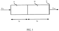
- the optical pathway shown is merely a hypothetical example of an optical pathway, and is intended to show how the invention works.
- the optical pathway shown in FIG. 1 comprises a first material 12 with a length x 1 , a second material 14 with a length x2, and a coating 16.
- phase function ⁇ ( ⁇ ) in each arm must be equal. However some simplifications can be made.
- OCT the signal is always produced by generating a carrier, either by sweeping the path length or in spectral OCT by sweeping across the frequency spectrum of the source. In either case this means the constant phase term ⁇ 0 in each arm can be ignored, and only the second and third terms ⁇ 1 and ⁇ 2 must be balanced for the reference and object arms.
- the reference arm 20 includes a first air portion 22, a glass portion 24 with a length x glass and composed of glass of a single glass type, a second air portion 26, a bulk component 28, a third air portion 30, and a discrete component 32.
- the bulk component is a component necessary to produce an output signal from the reference arm, such as a lens which collimates the light within the reference arm.
- the discrete component is a component necessary to produce an output signal from the reference arm, such as a mirror which reflects light reaching the end of the reference arm. More generally, there are zero or more bulk components and one or more discrete components. These components are the optical components within the reference arm necessary for the reference arm to produce an output signal. They are not components added merely to compensate for dispersion within the object arm.
- the dispersions in the segments of the reference arm are additive. Therefore the bulk component(s) and the discrete components can be considered as a single known component for the purposes of dispersion. Similarly, the various air portions can be considered as a single air portion for the purposes of dispersion.
- FIG. 3 a schematic representation of a reference arm used in OCT is shown according to one embodiment of the invention.
- the schematic representation 40 of the reference arm includes an air portion 42 with a length x air , a glass portion 44 with a length x glass of a single glass type, and a known components portion 46.
- the known components portion 46 represents at least one necessary and known optical component present in the reference arm. The at least one necessary and known optical component is necessary in order for the reference arm to produce an output signal, and is not present merely to compensate for dispersion in the object arm.
- the schematic representation of a reference arm shown in FIG. 3 can be used to represent the example reference arm shown in FIG. 2 .
- the various air portions 22, 26, and 30 of FIG. 2 can be represented as a single air portion 42 in FIG. 3 whose length x air is equal to the sum of the lengths of the individual air portions in FIG. 2 .
- the glass portion 24 of FIG. 2 is represented simply by an identical glass portion 44.
- the various known components 28 and 32 can be represented as a single known components portion 46.
- the total group delay for light passing through the reference arm is the sum of the group delay through each portion.
- ⁇ ref ,2 x glass ⁇ ⁇ glass ,2 + ⁇ known ,2 .
- the group delay and the group dispersion delay (GDD) of an object arm of the interferometer are determined.
- the GDD of the object arm is matched with the GDD of a hypothetical reference arm comprising an air portion, a glass portion comprising glass of a single glass type, and a known components portion.
- the glass type and the length of the glass portion is determined from the matching of the GDDs.
- the group delay of the object arm is matched with the group delay of the hypothetical reference arm.
- the length of the air portion is determined from the matching of the group delays, the glass type, and the length of the glass portion.
- a real reference arm can then be produced having an air portion and a glass portion each having the same properties as the air portion and the glass portion of the hypothetical reference arm.
- the total group delay of the object arm is determined.
- the total group delay is the sum of the group delays of the components within the object arm.
- the components within the object arm are known once the design of the object arm is complete, including their respective glass types and thicknesses.
- the total dispersion of the object arm can then be determined by referring to dispersion data for each glass type, although other methods of determining the total dispersion of the object arm can be used such as by using a modelling package.
- the additional dispersion from a patient's eye is included in the total dispersion of the object arm, for example by using the dispersion properties of water.
- the total GDD of the object arm, ⁇ obj,2 is determined.
- the GDD is determined in the same way as is the total group delay, i.e. by adding the dispersive contribution of each component within the object arm, including possibly the eye.
- the precise order of these two determinations is not important and they could in fact be determined simultaneously.
- a glass type can be chosen such that the above equality is satisfied while still giving a length x glass of the glass portion 44 that is practical for an OCT interferometer.
- the length x air of the air portion 42 can be determined.
- the total length of x air and x glass would not result in a practical length for the reference arm of an OCT interferometer, then a different glass type of the glass portion 44 can be used.
- a reference arm for use in an OCT interferometer can be built having these properties.
- the length of any one or more of the air portion or air portions can be set so that the total length of the air portion or air portions is equal to that determined total air portion length x air .
- an OCT interferometer having such a reference arm can be built.
- the invention has been described with reference to an OCT interferometer. More generally, the invention may be used to provide the reference arm of any interferometer.
- the invention has been described as placing a single glass portion of determined length and type in the reference arm of an OCT interferometer in order to compensate for differences in dispersion between the object arm and the reference arm of the OCT interferometer.
- a single glass can be placed in the object arm in order to compensate for such differences if the dispersion in the reference arm would otherwise be higher than that in the object arm, the length and type of glass being determined as described above.
Description
- This invention relates to balancing dispersion in broadband interferometers.
- In optical coherence tomography (OCT), the longitudinal resolution in an A-scan depends partly on the degree of similarity between dispersion in a reference arm and dispersion in an object arm. Dispersion is the term given when the propagation constant of a wave has a nonlinear dependence on frequency. The zero-th derivative of the phase function of the wave with respect to the frequency indicates the phase delay, the first derivative indicates the group delay, and the second derivative indicates the group delay dispersion.
- Generally the dispersive properties of a component will be known and the problem is to determine what effect this will have on a time varying signal. In interferometers the effect is well known and the problem then is to balance the dispersion in each arm.
- A dispersion imbalance in broadband interferometers causes a reduction of signal-to-noise and a broadening of the coherence profile, which in turn means a reduction in longitudinal resolution in an OCT A-scan. The presence of dispersive elements in the interferometer is not in itself the issue, but the dispersion in both arms of the interferometer must be balanced to achieve optimal signal-to-noise and resolution. Generally this is achieved by duplicating any element located in the object arm within the reference arm. For example, lenses are usually made up of different glass types or various thicknesses, and there are generally more in the object arm than in the reference arm. Each element within each arm may contribute to dispersion of the light within the arm, generally in different ways. A common technique therefore is to include extra pieces of glass in the reference path, matching the glass types and mean thicknesses in each lens in the object path, to compensate for the additional dispersion present in the object path. Each glass type is usually bonded together to form a compound rod which is included in the reference path. While this technique does ensure the mean dispersion in each arm of the interferometer is well matched, the cost and complexity of the interferometer are increased. In addition, there is an increase in multiple reflections due to boundaries between different materials and power loss.
-
US 2003-0004412 ,US 2005-0259265 and DREXLER W ET AL: "IN VIVO ULTRAHIGH-RESOLUTION OPTICAL COHERENCE TOMOGRAPHY", OPTICS LETTERS, OPTICAL SOCIETY OF AMERICA, vol. 24, no. 17, 1 September 1999 (1999-09-01), pages 1221-1223, ISSN: 0146-9592 all describe methods for compensating dispersion in interferometers for OCT. - There is a need to provide a system which equalized the dispersion in the arms of an interferometer without the cost and complexity of reproducing each functional element located in the object arm within the reference arm.
- By using a single glass type with a given thickness within the reference arm in order to mimic the dispersion characteristics of various elements within the object arm, the design of an OCT interferometer can be greatly simplified.
- In accordance with the present invention there is provided a method as set out in the accompanying claims.
- The features and advantages of embodiments of the invention will become more apparent from the following detailed description of the preferred embodiment(s) with reference to the attached figures, wherein:
-
FIG. 1 shows a hypothetical optical pathway; -
FIG. 2 shows a diagram of an example reference arm of an interferometer according to one embodiment of the invention; -
FIG. 3 shows a schematic representation of a reference arm of an interferometer according to one embodiment of the invention; and -
FIG. 4 shows a flowchart of a method by which the reference arm of an OCT interferometer is designed according to one embodiment of the invention. - It is noted that in the attached figures, like features bear similar labels.
- OCT interferometers contain various glass components, such as lenses, with varying physical properties, and generally the phase function φ(ω) is highly nonlinear. However for relatively narrow band sources (typical of OCT systems) and for frequencies far from an absorption edge (typically found in the ultraviolet for most glasses) the phase function can be accurately approximated by a Taylor series expansion:


- Given these conditions only terms up to second order are required, i.e. up to φ2. In bulk materials the phase function after propagation through a thickness of glass given by x, is related to the propagation constant of the material β such that:


- For propagation in a vacuum, to which propagation in air is a good approximation, the dependence of β on ω is known explicitly:

- The values of βn in a vacuum are found by differentiation to be:

- So far only a distributed form of dispersion, in which the phase shifts caused by propagation are directly proportional to the distance travelled, has been considered. There are also cases where the phase shifts can occur over very small regions of space. The use of dielectric coatings to produce mirrors, beam splitters and anti-reflection coatings are examples. The dispersive properties of these devices are dominated by their structure rather than the materials used to make them. These devices are best described by the total phase shift, φ(ω), that they induce after transmission or reflection of the input signal, in which case the previous derivations for φ(ω) can still be used.
- In a more complicated system made up from several elements, all that needs to be calculated is the total phase shift after passing through the system. Referring to
FIG. 1 , a hypothetical optical pathway is shown. The optical pathway shown is merely a hypothetical example of an optical pathway, and is intended to show how the invention works. The optical pathway shown inFIG. 1 comprises afirst material 12 with a length x 1, asecond material 14 with a length x2, and acoating 16. The total phase shift can be written as:
first material 12, thesecond material 14, and thecoating 16 respectively. Expanding each term as a Taylor series leads to expressions for the phase delay, group delay and GDD:
- To balance dispersion within the arms of an interferometer the phase function φ(ω) in each arm must be equal. However some simplifications can be made. In OCT the signal is always produced by generating a carrier, either by sweeping the path length or in spectral OCT by sweeping across the frequency spectrum of the source. In either case this means the constant phase term φ0 in each arm can be ignored, and only the second and third terms φ1 and φ2 must be balanced for the reference and object arms.
- Referring to
FIG. 2 , a diagram of an example reference arm used in an interferometer is shown according to one embodiment of the invention. Thereference arm 20 includes a first air portion 22, a glass portion 24 with a length x glass and composed of glass of a single glass type, asecond air portion 26, abulk component 28, athird air portion 30, and adiscrete component 32. - The bulk component is a component necessary to produce an output signal from the reference arm, such as a lens which collimates the light within the reference arm. The discrete component is a component necessary to produce an output signal from the reference arm, such as a mirror which reflects light reaching the end of the reference arm. More generally, there are zero or more bulk components and one or more discrete components. These components are the optical components within the reference arm necessary for the reference arm to produce an output signal. They are not components added merely to compensate for dispersion within the object arm.
- The dispersions in the segments of the reference arm are additive. Therefore the bulk component(s) and the discrete components can be considered as a single known component for the purposes of dispersion. Similarly, the various air portions can be considered as a single air portion for the purposes of dispersion. Referring to
FIG. 3 , a schematic representation of a reference arm used in OCT is shown according to one embodiment of the invention. The schematic representation 40 of the reference arm includes anair portion 42 with a length x air, aglass portion 44 with a length x glass of a single glass type, and aknown components portion 46. Theknown components portion 46 represents at least one necessary and known optical component present in the reference arm. The at least one necessary and known optical component is necessary in order for the reference arm to produce an output signal, and is not present merely to compensate for dispersion in the object arm. - The schematic representation of a reference arm shown in
FIG. 3 can be used to represent the example reference arm shown inFIG. 2 . Because dispersion is additive, thevarious air portions FIG. 2 can be represented as asingle air portion 42 inFIG. 3 whose length x air is equal to the sum of the lengths of the individual air portions inFIG. 2 . The glass portion 24 ofFIG. 2 is represented simply by anidentical glass portion 44. The various knowncomponents components portion 46. The dispersion Φknown of the knowncomponents portion 46 is equal to the sum of the dispersions of the known components, i.e.
- The total group delay for light passing through the reference arm is the sum of the group delay through each portion. The total group delay in the reference arm is therefore


- Similarly, the total GDD in the reference arm becomes

- Broadly, in producing a reference arm within an interferometer, the group delay and the group dispersion delay (GDD) of an object arm of the interferometer are determined. The GDD of the object arm is matched with the GDD of a hypothetical reference arm comprising an air portion, a glass portion comprising glass of a single glass type, and a known components portion. The glass type and the length of the glass portion is determined from the matching of the GDDs. In addition, the group delay of the object arm is matched with the group delay of the hypothetical reference arm. The length of the air portion is determined from the matching of the group delays, the glass type, and the length of the glass portion. A real reference arm can then be produced having an air portion and a glass portion each having the same properties as the air portion and the glass portion of the hypothetical reference arm.
- Referring to
FIG. 4 , a flowchart of a method by which a reference arm is produced according to one embodiment of the invention is shown. Atstep 60 the total group delay of the object arm, Φobj,1 is determined. As explained above, the total group delay is the sum of the group delays of the components within the object arm. The components within the object arm are known once the design of the object arm is complete, including their respective glass types and thicknesses. The total dispersion of the object arm can then be determined by referring to dispersion data for each glass type, although other methods of determining the total dispersion of the object arm can be used such as by using a modelling package. In one embodiment the additional dispersion from a patient's eye is included in the total dispersion of the object arm, for example by using the dispersion properties of water. - At
step 62 the total GDD of the object arm, Φobj,2, is determined. The GDD is determined in the same way as is the total group delay, i.e. by adding the dispersive contribution of each component within the object arm, including possibly the eye. Of course the precise order of these two determinations is not important and they could in fact be determined simultaneously. - At
step 64 the glass type and the length x glass of theglass portion 44 are determined by requiring that the dispersion in the reference arm is the same as the dispersion in the object arm, as desired in an OCT interferometer. Setting the GDD in each arm to be the same,

- Since the GDD of the object arm was determined at
step 62 and the GDD Φknown,2 of known components within the reference arm is known, a glass type can be chosen such that the above equality is satisfied while still giving a length x glass of theglass portion 44 that is practical for an OCT interferometer. Once the glass type and length x glass of theglass portion 44 are determined, then atstep 66 the length x air of theair portion 42 is determined by setting the group delay in each arm to be the same:

- Since the glass type of the
glass portion 44, and hence βglass,1, the length x glass, the group delay Φobj,1 within the object arm, and the group delay Φknown,1 of known and necessary components within the reference arm are known, the length x air of theair portion 42 can be determined. Of course if the total length of x air and x glass would not result in a practical length for the reference arm of an OCT interferometer, then a different glass type of theglass portion 44 can be used. - Once the glass type, the length of the glass portion, and the total length of the air portion or air portions are determined, a reference arm for use in an OCT interferometer can be built having these properties. The length of any one or more of the air portion or air portions can be set so that the total length of the air portion or air portions is equal to that determined total air portion length x air. Similarly an OCT interferometer having such a reference arm can be built.
- The invention has been described with reference to an OCT interferometer. More generally, the invention may be used to provide the reference arm of any interferometer.
- The invention has been described as placing a single glass portion of determined length and type in the reference arm of an OCT interferometer in order to compensate for differences in dispersion between the object arm and the reference arm of the OCT interferometer. Alternatively, a single glass can be placed in the object arm in order to compensate for such differences if the dispersion in the reference arm would otherwise be higher than that in the object arm, the length and type of glass being determined as described above.
- The scope of the invention is solely defined by the appended claims.
Claims (4)
- A method of producing a reference arm within an interferometer, comprising:determining the group delay and the group dispersion delay, GDD, of an object arm of the interferometer (60,62);determining the dispersion of known components (46) within the reference arm, the known components being necessary for production of an output signal from the reference arm when in use;matching the GDD of the object arm with the GDD of a hypothetical reference arm comprising an air portion, a glass portion comprising glass of a single glass type, and a known components portion having a dispersion equal to the dispersion of the known components;determining the glass type and the length of the glass portion from the matching of the GDDs (64);matching the group delay of the object arm with the group delay of the hypothetical reference arm;determining the total length of the air portion from the matching of the group delays, the glass type, and the length of the glass portion (66); andproducing a real reference arm, whose sum of the lengths of at least one air portion (42) within the reference arm is equal to the total length of the air portion of the hypothetical reference arm, and having a glass portion (44) having the same properties as the glass portion of the hypothetical reference arm.
- The method of claim 1 wherein matching the GDD of the object arm with the GDD of the hypothetical reference arm comprises setting
 where x glass is the length of the glass portion, βglass,2 is the second derivative of the propagation constant of the glass portion with respect to frequency, Φknown,2 is the GDD of the known components portion, and Φobj,2 is the GDD of the object arm,and wherein matching the group delay of the object arm with the group delay of the hypothetical reference arm comprises setting
 where x air is the length of the air portion, c is the speed of light in a vacuum, βglass,1 is the first derivative of the propagation constant of the glass portion with respect to frequency, Φknown,1 is the group delay of the known components portion, and Φobj,1 is the group delay of the object arm.
 - The method of claim 1 wherein the glass type is determined such that the real reference arm can be used in an optical coherence tomography interferometer.
- The method of claim 1 wherein the group delay and the GDD of the object arm include the group delay and the GDD of a hypothetical patient eye.
Applications Claiming Priority (2)
| Application Number | Priority Date | Filing Date | Title |
|---|---|---|---|
| US201462010643P | 2014-06-11 | 2014-06-11 | |
| PCT/CA2015/000375 WO2015188258A1 (en) | 2014-06-11 | 2015-06-11 | Dispersion compensation |
Publications (3)
| Publication Number | Publication Date |
|---|---|
| EP3155362A1 EP3155362A1 (en) | 2017-04-19 |
| EP3155362A4 EP3155362A4 (en) | 2017-11-22 |
| EP3155362B1 true EP3155362B1 (en) | 2018-12-12 |
Family
ID=54832648
Family Applications (1)
| Application Number | Title | Priority Date | Filing Date |
|---|---|---|---|
| EP15806034.3A Active EP3155362B1 (en) | 2014-06-11 | 2015-06-11 | Dispersion compensation |
Country Status (4)
| Country | Link |
|---|---|
| US (1) | US10048056B2 (en) |
| EP (1) | EP3155362B1 (en) |
| JP (3) | JP6800840B2 (en) |
| WO (1) | WO2015188258A1 (en) |
Family Cites Families (15)
| Publication number | Priority date | Publication date | Assignee | Title |
|---|---|---|---|---|
| US6615072B1 (en) | 1999-02-04 | 2003-09-02 | Olympus Optical Co., Ltd. | Optical imaging device |
| DE10039239A1 (en) * | 2000-08-11 | 2002-03-07 | Bosch Gmbh Robert | Optical measurement device has image flattening optics for detecting/flattening curved surface area or panoramic optics for detecting radial symmetrical surface area over 360 degrees |
| TW200604695A (en) | 2004-05-18 | 2006-02-01 | Zygo Corp | Methods and systems for determining optical properties using low-coherence interference signals |
| EP1928297B1 (en) * | 2005-09-29 | 2010-11-03 | Bioptigen, Inc. | Portable optical coherence tomography devices and related systems |
| JP2007181632A (en) * | 2006-01-10 | 2007-07-19 | Topcon Corp | Fundus observation device |
| US7719692B2 (en) * | 2006-04-28 | 2010-05-18 | Bioptigen, Inc. | Methods, systems and computer program products for optical coherence tomography (OCT) using automatic dispersion compensation |
| CN100464696C (en) | 2007-04-24 | 2009-03-04 | 浙江大学 | Spectral coverage OCT imaging method based on optical scanning delay line and the system |
| CN100493444C (en) | 2007-12-12 | 2009-06-03 | 中国科学院上海光学精密机械研究所 | High resolution optical coherence tomography imaging mehtod |
| WO2011050249A1 (en) * | 2009-10-23 | 2011-04-28 | Bioptigen, Inc. | Systems for comprehensive fourier domain optical coherence tomography (fdoct) and related methods |
| US8705041B2 (en) * | 2010-05-27 | 2014-04-22 | Promet International, Inc. | Coaxial interferometer and inspection probe |
| ES2396784B2 (en) | 2011-03-15 | 2014-07-23 | Medlumics, S.L. | INTEGRABLE ACTIVE EQUALIZATION SYSTEM OF CHROMATIC DISPERSION. |
| JP5220208B2 (en) * | 2011-03-31 | 2013-06-26 | キヤノン株式会社 | Control device, imaging control method, and program |
| JP5930620B2 (en) * | 2011-06-28 | 2016-06-08 | キヤノン株式会社 | Optical coherence tomography apparatus and method |
| CN104755908B (en) * | 2012-07-27 | 2017-12-12 | 统雷有限公司 | Quick imaging system |
| WO2015044232A1 (en) * | 2013-09-25 | 2015-04-02 | Carl Zeiss Meditec Ag | Methods and systems for modifying second-order chromatic dispersion in optical coherence tomographic systems |
-
2015
- 2015-06-11 EP EP15806034.3A patent/EP3155362B1/en active Active
- 2015-06-11 JP JP2017517153A patent/JP6800840B2/en active Active
- 2015-06-11 US US15/318,234 patent/US10048056B2/en active Active
- 2015-06-11 WO PCT/CA2015/000375 patent/WO2015188258A1/en active Application Filing
-
2020
- 2020-06-01 JP JP2020095357A patent/JP2020144149A/en active Pending
-
2022
- 2022-11-11 JP JP2022181143A patent/JP2023015279A/en active Pending
Non-Patent Citations (1)
| Title |
|---|
| None * |
Also Published As
| Publication number | Publication date |
|---|---|
| JP2023015279A (en) | 2023-01-31 |
| WO2015188258A1 (en) | 2015-12-17 |
| JP2017517751A (en) | 2017-06-29 |
| EP3155362A1 (en) | 2017-04-19 |
| EP3155362A4 (en) | 2017-11-22 |
| US10048056B2 (en) | 2018-08-14 |
| JP6800840B2 (en) | 2020-12-16 |
| JP2020144149A (en) | 2020-09-10 |
| US20170108328A1 (en) | 2017-04-20 |
Similar Documents
| Publication | Publication Date | Title |
|---|---|---|
| Bergeron et al. | Femtosecond time synchronization of optical clocks off of a flying quadcopter | |
| Scharmer et al. | Is the sky the limit?-Performance of the revamped Swedish 1-m Solar Telescope and its blue-and red-beam reimaging systems | |
| Diolaiti et al. | Preparing for the phase B of the E-ELT MCAO module project | |
| Singh et al. | Estimation and compensation of dispersion for a high-resolution optical coherence tomography system | |
| Podgorski et al. | A novel systems engineering approach to the design of a precision radial velocity spectrograph: the GMT-Consortium Large Earth Finder (G-CLEF) | |
| Coudé du Foresto et al. | Minimization of fiber dispersion effects in double Fourier stellar interferometers. | |
| Sasso et al. | Telescope jitters and phase noise in the LISA interferometer | |
| Molodij et al. | Angular correlation of Zernike polynomials for a laser guide star in adaptive optics | |
| Englert et al. | High-efficiency echelle gratings for MIGHTI, the spatial heterodyne interferometers for the ICON mission | |
| Dolkens et al. | Active correction system of a deployable telescope for Earth observation | |
| González et al. | General formulation for the calibration and characterization of narrow-gap etalons: the OSIRIS/GTC tunable filters case | |
| Kalensky et al. | In-flight measurement of atmospheric-imposed tilt: experimental results and analysis | |
| EP3155362B1 (en) | Dispersion compensation | |
| Mandel et al. | Architecture and performance analysis of an optical metrology terminal for satellite-to-satellite laser ranging | |
| Hutterer et al. | A mathematical framework for nonlinear wavefront reconstruction in adaptive optics systems with Fourier-type wavefront sensing | |
| Correia et al. | Increased sky coverage with optimal correction of tilt and tilt-anisoplanatism modes in laser-guide-star multiconjugate adaptive optics | |
| Hicks et al. | Demonstrating broadband billion-to-one contrast with the Visible Nulling Coronagraph | |
| Poliak et al. | Fiber coupling and field mixing of coherent free-space optical beams in satellite communications | |
| Huttner et al. | Comparison of different sloshing speedmeters | |
| Berger et al. | Preliminary results from the longitudinal dispersion compensation system for the CHARA array | |
| WO2010096912A1 (en) | System and method for a virtual reference interferometer | |
| Strigin | The effect of parametric oscillatory instability in a fabry-perot cavity of the einstein telescope | |
| Wang et al. | Analysis of the improvement in sky coverage for multiconjugate adaptive optics systems obtained using minimum variance split tomography | |
| Rosenberg | Improvements in birefringent filters. 5: Field of view effects | |
| Perrin et al. | Single-mode waveguides for GRAVITY-II. Single-mode fibers and Fiber Control Unit |
Legal Events
| Date | Code | Title | Description |
|---|---|---|---|
| STAA | Information on the status of an ep patent application or granted ep patent |
Free format text: STATUS: THE INTERNATIONAL PUBLICATION HAS BEEN MADE |
|
| PUAI | Public reference made under article 153(3) epc to a published international application that has entered the european phase |
Free format text: ORIGINAL CODE: 0009012 |
|
| STAA | Information on the status of an ep patent application or granted ep patent |
Free format text: STATUS: REQUEST FOR EXAMINATION WAS MADE |
|
| 17P | Request for examination filed |
Effective date: 20161221 |
|
| AK | Designated contracting states |
Kind code of ref document: A1 Designated state(s): AL AT BE BG CH CY CZ DE DK EE ES FI FR GB GR HR HU IE IS IT LI LT LU LV MC MK MT NL NO PL PT RO RS SE SI SK SM TR |
|
| AX | Request for extension of the european patent |
Extension state: BA ME |
|
| DAV | Request for validation of the european patent (deleted) | ||
| DAX | Request for extension of the european patent (deleted) | ||
| A4 | Supplementary search report drawn up and despatched |
Effective date: 20171019 |
|
| RIC1 | Information provided on ipc code assigned before grant |
Ipc: G01B 9/02 20060101AFI20171013BHEP Ipc: A61B 3/10 20060101ALI20171013BHEP |
|
| REG | Reference to a national code |
Ref country code: HK Ref legal event code: DE Ref document number: 1236608 Country of ref document: HK |
|
| GRAP | Despatch of communication of intention to grant a patent |
Free format text: ORIGINAL CODE: EPIDOSNIGR1 |
|
| STAA | Information on the status of an ep patent application or granted ep patent |
Free format text: STATUS: GRANT OF PATENT IS INTENDED |
|
| INTG | Intention to grant announced |
Effective date: 20180703 |
|
| GRAS | Grant fee paid |
Free format text: ORIGINAL CODE: EPIDOSNIGR3 |
|
| GRAA | (expected) grant |
Free format text: ORIGINAL CODE: 0009210 |
|
| STAA | Information on the status of an ep patent application or granted ep patent |
Free format text: STATUS: THE PATENT HAS BEEN GRANTED |
|
| AK | Designated contracting states |
Kind code of ref document: B1 Designated state(s): AL AT BE BG CH CY CZ DE DK EE ES FI FR GB GR HR HU IE IS IT LI LT LU LV MC MK MT NL NO PL PT RO RS SE SI SK SM TR |
|
| REG | Reference to a national code |
Ref country code: GB Ref legal event code: FG4D |
|
| REG | Reference to a national code |
Ref country code: CH Ref legal event code: EP |
|
| REG | Reference to a national code |
Ref country code: AT Ref legal event code: REF Ref document number: 1076605 Country of ref document: AT Kind code of ref document: T Effective date: 20181215 |
|
| REG | Reference to a national code |
Ref country code: DE Ref legal event code: R096 Ref document number: 602015021618 Country of ref document: DE |
|
| REG | Reference to a national code |
Ref country code: IE Ref legal event code: FG4D |
|
| REG | Reference to a national code |
Ref country code: NL Ref legal event code: MP Effective date: 20181212 |
|
| REG | Reference to a national code |
Ref country code: LT Ref legal event code: MG4D |
|
| PG25 | Lapsed in a contracting state [announced via postgrant information from national office to epo] |
Ref country code: HR Free format text: LAPSE BECAUSE OF FAILURE TO SUBMIT A TRANSLATION OF THE DESCRIPTION OR TO PAY THE FEE WITHIN THE PRESCRIBED TIME-LIMIT Effective date: 20181212 Ref country code: NO Free format text: LAPSE BECAUSE OF FAILURE TO SUBMIT A TRANSLATION OF THE DESCRIPTION OR TO PAY THE FEE WITHIN THE PRESCRIBED TIME-LIMIT Effective date: 20190312 Ref country code: BG Free format text: LAPSE BECAUSE OF FAILURE TO SUBMIT A TRANSLATION OF THE DESCRIPTION OR TO PAY THE FEE WITHIN THE PRESCRIBED TIME-LIMIT Effective date: 20190312 Ref country code: ES Free format text: LAPSE BECAUSE OF FAILURE TO SUBMIT A TRANSLATION OF THE DESCRIPTION OR TO PAY THE FEE WITHIN THE PRESCRIBED TIME-LIMIT Effective date: 20181212 Ref country code: LT Free format text: LAPSE BECAUSE OF FAILURE TO SUBMIT A TRANSLATION OF THE DESCRIPTION OR TO PAY THE FEE WITHIN THE PRESCRIBED TIME-LIMIT Effective date: 20181212 Ref country code: LV Free format text: LAPSE BECAUSE OF FAILURE TO SUBMIT A TRANSLATION OF THE DESCRIPTION OR TO PAY THE FEE WITHIN THE PRESCRIBED TIME-LIMIT Effective date: 20181212 Ref country code: FI Free format text: LAPSE BECAUSE OF FAILURE TO SUBMIT A TRANSLATION OF THE DESCRIPTION OR TO PAY THE FEE WITHIN THE PRESCRIBED TIME-LIMIT Effective date: 20181212 |
|
| REG | Reference to a national code |
Ref country code: AT Ref legal event code: MK05 Ref document number: 1076605 Country of ref document: AT Kind code of ref document: T Effective date: 20181212 |
|
| PG25 | Lapsed in a contracting state [announced via postgrant information from national office to epo] |
Ref country code: AL Free format text: LAPSE BECAUSE OF FAILURE TO SUBMIT A TRANSLATION OF THE DESCRIPTION OR TO PAY THE FEE WITHIN THE PRESCRIBED TIME-LIMIT Effective date: 20181212 Ref country code: SE Free format text: LAPSE BECAUSE OF FAILURE TO SUBMIT A TRANSLATION OF THE DESCRIPTION OR TO PAY THE FEE WITHIN THE PRESCRIBED TIME-LIMIT Effective date: 20181212 Ref country code: RS Free format text: LAPSE BECAUSE OF FAILURE TO SUBMIT A TRANSLATION OF THE DESCRIPTION OR TO PAY THE FEE WITHIN THE PRESCRIBED TIME-LIMIT Effective date: 20181212 Ref country code: GR Free format text: LAPSE BECAUSE OF FAILURE TO SUBMIT A TRANSLATION OF THE DESCRIPTION OR TO PAY THE FEE WITHIN THE PRESCRIBED TIME-LIMIT Effective date: 20190313 |
|
| PG25 | Lapsed in a contracting state [announced via postgrant information from national office to epo] |
Ref country code: NL Free format text: LAPSE BECAUSE OF FAILURE TO SUBMIT A TRANSLATION OF THE DESCRIPTION OR TO PAY THE FEE WITHIN THE PRESCRIBED TIME-LIMIT Effective date: 20181212 |
|
| PG25 | Lapsed in a contracting state [announced via postgrant information from national office to epo] |
Ref country code: IT Free format text: LAPSE BECAUSE OF FAILURE TO SUBMIT A TRANSLATION OF THE DESCRIPTION OR TO PAY THE FEE WITHIN THE PRESCRIBED TIME-LIMIT Effective date: 20181212 Ref country code: PL Free format text: LAPSE BECAUSE OF FAILURE TO SUBMIT A TRANSLATION OF THE DESCRIPTION OR TO PAY THE FEE WITHIN THE PRESCRIBED TIME-LIMIT Effective date: 20181212 Ref country code: PT Free format text: LAPSE BECAUSE OF FAILURE TO SUBMIT A TRANSLATION OF THE DESCRIPTION OR TO PAY THE FEE WITHIN THE PRESCRIBED TIME-LIMIT Effective date: 20190412 Ref country code: CZ Free format text: LAPSE BECAUSE OF FAILURE TO SUBMIT A TRANSLATION OF THE DESCRIPTION OR TO PAY THE FEE WITHIN THE PRESCRIBED TIME-LIMIT Effective date: 20181212 |
|
| PG25 | Lapsed in a contracting state [announced via postgrant information from national office to epo] |
Ref country code: RO Free format text: LAPSE BECAUSE OF FAILURE TO SUBMIT A TRANSLATION OF THE DESCRIPTION OR TO PAY THE FEE WITHIN THE PRESCRIBED TIME-LIMIT Effective date: 20181212 Ref country code: IS Free format text: LAPSE BECAUSE OF FAILURE TO SUBMIT A TRANSLATION OF THE DESCRIPTION OR TO PAY THE FEE WITHIN THE PRESCRIBED TIME-LIMIT Effective date: 20190412 Ref country code: SK Free format text: LAPSE BECAUSE OF FAILURE TO SUBMIT A TRANSLATION OF THE DESCRIPTION OR TO PAY THE FEE WITHIN THE PRESCRIBED TIME-LIMIT Effective date: 20181212 Ref country code: EE Free format text: LAPSE BECAUSE OF FAILURE TO SUBMIT A TRANSLATION OF THE DESCRIPTION OR TO PAY THE FEE WITHIN THE PRESCRIBED TIME-LIMIT Effective date: 20181212 Ref country code: SM Free format text: LAPSE BECAUSE OF FAILURE TO SUBMIT A TRANSLATION OF THE DESCRIPTION OR TO PAY THE FEE WITHIN THE PRESCRIBED TIME-LIMIT Effective date: 20181212 |
|
| REG | Reference to a national code |
Ref country code: DE Ref legal event code: R097 Ref document number: 602015021618 Country of ref document: DE |
|
| PLBE | No opposition filed within time limit |
Free format text: ORIGINAL CODE: 0009261 |
|
| STAA | Information on the status of an ep patent application or granted ep patent |
Free format text: STATUS: NO OPPOSITION FILED WITHIN TIME LIMIT |
|
| PG25 | Lapsed in a contracting state [announced via postgrant information from national office to epo] |
Ref country code: DK Free format text: LAPSE BECAUSE OF FAILURE TO SUBMIT A TRANSLATION OF THE DESCRIPTION OR TO PAY THE FEE WITHIN THE PRESCRIBED TIME-LIMIT Effective date: 20181212 Ref country code: AT Free format text: LAPSE BECAUSE OF FAILURE TO SUBMIT A TRANSLATION OF THE DESCRIPTION OR TO PAY THE FEE WITHIN THE PRESCRIBED TIME-LIMIT Effective date: 20181212 Ref country code: SI Free format text: LAPSE BECAUSE OF FAILURE TO SUBMIT A TRANSLATION OF THE DESCRIPTION OR TO PAY THE FEE WITHIN THE PRESCRIBED TIME-LIMIT Effective date: 20181212 |
|
| 26N | No opposition filed |
Effective date: 20190913 |
|
| PG25 | Lapsed in a contracting state [announced via postgrant information from national office to epo] |
Ref country code: MC Free format text: LAPSE BECAUSE OF FAILURE TO SUBMIT A TRANSLATION OF THE DESCRIPTION OR TO PAY THE FEE WITHIN THE PRESCRIBED TIME-LIMIT Effective date: 20181212 |
|
| REG | Reference to a national code |
Ref country code: CH Ref legal event code: PL |
|
| GBPC | Gb: european patent ceased through non-payment of renewal fee |
Effective date: 20190611 |
|
| REG | Reference to a national code |
Ref country code: BE Ref legal event code: MM Effective date: 20190630 |
|
| PG25 | Lapsed in a contracting state [announced via postgrant information from national office to epo] |
Ref country code: TR Free format text: LAPSE BECAUSE OF FAILURE TO SUBMIT A TRANSLATION OF THE DESCRIPTION OR TO PAY THE FEE WITHIN THE PRESCRIBED TIME-LIMIT Effective date: 20181212 |
|
| PG25 | Lapsed in a contracting state [announced via postgrant information from national office to epo] |
Ref country code: IE Free format text: LAPSE BECAUSE OF NON-PAYMENT OF DUE FEES Effective date: 20190611 Ref country code: GB Free format text: LAPSE BECAUSE OF NON-PAYMENT OF DUE FEES Effective date: 20190611 |
|
| PG25 | Lapsed in a contracting state [announced via postgrant information from national office to epo] |
Ref country code: BE Free format text: LAPSE BECAUSE OF NON-PAYMENT OF DUE FEES Effective date: 20190630 Ref country code: CH Free format text: LAPSE BECAUSE OF NON-PAYMENT OF DUE FEES Effective date: 20190630 Ref country code: LU Free format text: LAPSE BECAUSE OF NON-PAYMENT OF DUE FEES Effective date: 20190611 Ref country code: LI Free format text: LAPSE BECAUSE OF NON-PAYMENT OF DUE FEES Effective date: 20190630 |
|
| PG25 | Lapsed in a contracting state [announced via postgrant information from national office to epo] |
Ref country code: CY Free format text: LAPSE BECAUSE OF FAILURE TO SUBMIT A TRANSLATION OF THE DESCRIPTION OR TO PAY THE FEE WITHIN THE PRESCRIBED TIME-LIMIT Effective date: 20181212 |
|
| PG25 | Lapsed in a contracting state [announced via postgrant information from national office to epo] |
Ref country code: HU Free format text: LAPSE BECAUSE OF FAILURE TO SUBMIT A TRANSLATION OF THE DESCRIPTION OR TO PAY THE FEE WITHIN THE PRESCRIBED TIME-LIMIT; INVALID AB INITIO Effective date: 20150611 Ref country code: MT Free format text: LAPSE BECAUSE OF FAILURE TO SUBMIT A TRANSLATION OF THE DESCRIPTION OR TO PAY THE FEE WITHIN THE PRESCRIBED TIME-LIMIT Effective date: 20181212 |
|
| PG25 | Lapsed in a contracting state [announced via postgrant information from national office to epo] |
Ref country code: MK Free format text: LAPSE BECAUSE OF FAILURE TO SUBMIT A TRANSLATION OF THE DESCRIPTION OR TO PAY THE FEE WITHIN THE PRESCRIBED TIME-LIMIT Effective date: 20181212 |
|
| PGFP | Annual fee paid to national office [announced via postgrant information from national office to epo] |
Ref country code: FR Payment date: 20230316 Year of fee payment: 9 |
|
| P01 | Opt-out of the competence of the unified patent court (upc) registered |
Effective date: 20230526 |
|
| PGFP | Annual fee paid to national office [announced via postgrant information from national office to epo] |
Ref country code: DE Payment date: 20230315 Year of fee payment: 9 |