EP3154318B1 - System for controlling illumination in a road tunnel and method of estimating a veiling luminance - Google Patents
System for controlling illumination in a road tunnel and method of estimating a veiling luminance Download PDFInfo
- Publication number
- EP3154318B1 EP3154318B1 EP16192220.8A EP16192220A EP3154318B1 EP 3154318 B1 EP3154318 B1 EP 3154318B1 EP 16192220 A EP16192220 A EP 16192220A EP 3154318 B1 EP3154318 B1 EP 3154318B1
- Authority
- EP
- European Patent Office
- Prior art keywords
- luminance
- image sensor
- driver
- estimation
- viewing pose
- Prior art date
- Legal status (The legal status is an assumption and is not a legal conclusion. Google has not performed a legal analysis and makes no representation as to the accuracy of the status listed.)
- Not-in-force
Links
Images



Classifications
-
- H—ELECTRICITY
- H05—ELECTRIC TECHNIQUES NOT OTHERWISE PROVIDED FOR
- H05B—ELECTRIC HEATING; ELECTRIC LIGHT SOURCES NOT OTHERWISE PROVIDED FOR; CIRCUIT ARRANGEMENTS FOR ELECTRIC LIGHT SOURCES, IN GENERAL
- H05B47/00—Circuit arrangements for operating light sources in general, i.e. where the type of light source is not relevant
- H05B47/10—Controlling the light source
- H05B47/105—Controlling the light source in response to determined parameters
-
- F—MECHANICAL ENGINEERING; LIGHTING; HEATING; WEAPONS; BLASTING
- F21—LIGHTING
- F21S—NON-PORTABLE LIGHTING DEVICES; SYSTEMS THEREOF; VEHICLE LIGHTING DEVICES SPECIALLY ADAPTED FOR VEHICLE EXTERIORS
- F21S8/00—Lighting devices intended for fixed installation
- F21S8/04—Lighting devices intended for fixed installation intended only for mounting on a ceiling or the like overhead structures
-
- G—PHYSICS
- G01—MEASURING; TESTING
- G01J—MEASUREMENT OF INTENSITY, VELOCITY, SPECTRAL CONTENT, POLARISATION, PHASE OR PULSE CHARACTERISTICS OF INFRARED, VISIBLE OR ULTRAVIOLET LIGHT; COLORIMETRY; RADIATION PYROMETRY
- G01J1/00—Photometry, e.g. photographic exposure meter
- G01J1/42—Photometry, e.g. photographic exposure meter using electric radiation detectors
-
- G—PHYSICS
- G06—COMPUTING OR CALCULATING; COUNTING
- G06T—IMAGE DATA PROCESSING OR GENERATION, IN GENERAL
- G06T5/00—Image enhancement or restoration
- G06T5/80—Geometric correction
-
- G—PHYSICS
- G06—COMPUTING OR CALCULATING; COUNTING
- G06V—IMAGE OR VIDEO RECOGNITION OR UNDERSTANDING
- G06V20/00—Scenes; Scene-specific elements
- G06V20/50—Context or environment of the image
- G06V20/56—Context or environment of the image exterior to a vehicle by using sensors mounted on the vehicle
-
- H—ELECTRICITY
- H05—ELECTRIC TECHNIQUES NOT OTHERWISE PROVIDED FOR
- H05B—ELECTRIC HEATING; ELECTRIC LIGHT SOURCES NOT OTHERWISE PROVIDED FOR; CIRCUIT ARRANGEMENTS FOR ELECTRIC LIGHT SOURCES, IN GENERAL
- H05B47/00—Circuit arrangements for operating light sources in general, i.e. where the type of light source is not relevant
- H05B47/10—Controlling the light source
-
- H—ELECTRICITY
- H05—ELECTRIC TECHNIQUES NOT OTHERWISE PROVIDED FOR
- H05B—ELECTRIC HEATING; ELECTRIC LIGHT SOURCES NOT OTHERWISE PROVIDED FOR; CIRCUIT ARRANGEMENTS FOR ELECTRIC LIGHT SOURCES, IN GENERAL
- H05B47/00—Circuit arrangements for operating light sources in general, i.e. where the type of light source is not relevant
- H05B47/10—Controlling the light source
- H05B47/105—Controlling the light source in response to determined parameters
- H05B47/11—Controlling the light source in response to determined parameters by determining the brightness or colour temperature of ambient light
-
- F—MECHANICAL ENGINEERING; LIGHTING; HEATING; WEAPONS; BLASTING
- F21—LIGHTING
- F21V—FUNCTIONAL FEATURES OR DETAILS OF LIGHTING DEVICES OR SYSTEMS THEREOF; STRUCTURAL COMBINATIONS OF LIGHTING DEVICES WITH OTHER ARTICLES, NOT OTHERWISE PROVIDED FOR
- F21V23/00—Arrangement of electric circuit elements in or on lighting devices
- F21V23/04—Arrangement of electric circuit elements in or on lighting devices the elements being switches
- F21V23/0442—Arrangement of electric circuit elements in or on lighting devices the elements being switches activated by means of a sensor, e.g. motion or photodetectors
- F21V23/0464—Arrangement of electric circuit elements in or on lighting devices the elements being switches activated by means of a sensor, e.g. motion or photodetectors the sensor sensing the level of ambient illumination, e.g. dawn or dusk sensors
-
- F—MECHANICAL ENGINEERING; LIGHTING; HEATING; WEAPONS; BLASTING
- F21—LIGHTING
- F21W—INDEXING SCHEME ASSOCIATED WITH SUBCLASSES F21K, F21L, F21S and F21V, RELATING TO USES OR APPLICATIONS OF LIGHTING DEVICES OR SYSTEMS
- F21W2131/00—Use or application of lighting devices or systems not provided for in codes F21W2102/00-F21W2121/00
- F21W2131/10—Outdoor lighting
- F21W2131/101—Outdoor lighting of tunnels or the like, e.g. under bridges
-
- G—PHYSICS
- G01—MEASURING; TESTING
- G01J—MEASUREMENT OF INTENSITY, VELOCITY, SPECTRAL CONTENT, POLARISATION, PHASE OR PULSE CHARACTERISTICS OF INFRARED, VISIBLE OR ULTRAVIOLET LIGHT; COLORIMETRY; RADIATION PYROMETRY
- G01J1/00—Photometry, e.g. photographic exposure meter
- G01J1/42—Photometry, e.g. photographic exposure meter using electric radiation detectors
- G01J1/44—Electric circuits
- G01J2001/4446—Type of detector
- G01J2001/448—Array [CCD]
-
- Y—GENERAL TAGGING OF NEW TECHNOLOGICAL DEVELOPMENTS; GENERAL TAGGING OF CROSS-SECTIONAL TECHNOLOGIES SPANNING OVER SEVERAL SECTIONS OF THE IPC; TECHNICAL SUBJECTS COVERED BY FORMER USPC CROSS-REFERENCE ART COLLECTIONS [XRACs] AND DIGESTS
- Y02—TECHNOLOGIES OR APPLICATIONS FOR MITIGATION OR ADAPTATION AGAINST CLIMATE CHANGE
- Y02B—CLIMATE CHANGE MITIGATION TECHNOLOGIES RELATED TO BUILDINGS, e.g. HOUSING, HOUSE APPLIANCES OR RELATED END-USER APPLICATIONS
- Y02B20/00—Energy efficient lighting technologies, e.g. halogen lamps or gas discharge lamps
- Y02B20/40—Control techniques providing energy savings, e.g. smart controller or presence detection
Definitions
- the luminance sensor used for measuring the veiling luminance is often arranged considerably higher than the driver approaching the tunnel entrance. It is therefore likely that the veiling luminance measured by such a luminance sensor will not be correct, as the tunnel entrance scene will be different for the different heights.
- the inventors have further realized that an improved estimation of the veiling luminance experienced by a driver can be achieved by estimating the veiling luminance based on an image captured by an image sensor, and the application of image processing that is dependent on a relation between a driver viewing pose and an image sensor viewing pose.
- Embodiments of the above method of estimating the veiling luminance may, furthermore, be included in a method of controlling illumination in a road tunnel using an illumination control system comprising: at least one light-source arranged inside the road tunnel for illuminating an interior of the road tunnel; a veiling luminance estimation system arranged outside the tunnel for estimating a veiling luminance experienced by a driver exhibiting a driver viewing pose towards a tunnel entrance of the road tunnel, the veiling luminance estimation system comprising: an image sensor exhibiting an image sensor viewing pose towards the tunnel entrance, different from the driver viewing pose; image acquisition circuitry connected to the image sensor for acquiring an image of a tunnel entrance scene, the image comprising a plurality of pixels; and veiling luminance estimation circuitry connected to the image acquisition circuitry; and a lighting controller connected to the veiling luminance estimation system and to the at least one light-source for controlling at least one property of light emitted by the at least one light-source based on the estimated veiling luminance, further comprising the steps of providing the estimated veiling
Landscapes
- Engineering & Computer Science (AREA)
- Physics & Mathematics (AREA)
- General Physics & Mathematics (AREA)
- Theoretical Computer Science (AREA)
- Multimedia (AREA)
- Spectroscopy & Molecular Physics (AREA)
- General Engineering & Computer Science (AREA)
- Image Processing (AREA)
- Circuit Arrangement For Electric Light Sources In General (AREA)
Description
- The present invention relates to a system for controlling illumination in a road tunnel and to a method of estimating a veiling luminance.
- For a driver approaching a road tunnel, it may be difficult to distinguish objects just inside the tunnel. To provide for a safe approach to and passage through the tunnel, there are guides for the lighting of road tunnels. One such guide is CIE 88:2004 "GUIDE FOR THE LIGHTING OF ROAD TUNNELS AND UNDERPASSES" with ISBN no: 3 901 906 31 2.
- In this guide, instructions are provided for how to determine the so-called threshold luminance that the tunnel illumination should provide. According to the guide, one important parameter for determining the threshold luminance is the so-called veiling luminance. The veiling luminance, which is a measure of glare forming a "veil" over the eye and hindering the eye's ability to see, contains terms related to scattering in the atmosphere, in the windscreen of the vehicle and inside the eye of the driver.
- Since the veiling luminance will vary depending on various factors, such as the configuration of the tunnel entrance scene as seen from the so-called stopping distance, the time of day, the time of year and the weather etc, dimensioning the tunnel illumination for the worst case will most likely result in excessive energy consumption and may even cause problems due to too bright illumination.
- To handle this situation, adaptive tunnel illumination systems exist, in which a luminance sensor is provided outside the tunnel and directed towards the tunnel entrance. The output of the luminance sensor is used as input for the control of the tunnel illumination.
- Although being considerably better than non-adaptive tunnel illumination, it would appear that there is still room for improvement of the existing adaptive tunnel illumination control systems, in particular in respect of the accuracy in the estimation of the veiling luminance.
- It would thus be desirable to provide an improved system for controlling illumination in a road tunnel, in particular providing for increased accuracy in the estimation of the veiling luminance.
-
JP2008241380 - In view of above-mentioned and other drawbacks of the prior art, it is an object of the present invention to provide for increased accuracy in the estimation of veiling luminance to allow for improved control of the illumination in a road tunnel.
- According to a first aspect of the present invention, it is therefore provided a system for controlling illumination in a road tunnel, comprising: at least one light-source arranged inside the road tunnel for illuminating an interior of the road tunnel; a veiling luminance estimation system for estimating a veiling luminance experienced by a driver exhibiting a driver viewing pose towards a tunnel entrance of the road tunnel, the driver viewing pose defining at least a driver vertical position and a driver viewing direction; and a lighting controller connected to the veiling luminance estimation system and to the at least one light-source for controlling at least one property of light emitted by the at least one light-source based on the estimated veiling luminance, wherein the veiling luminance estimation system comprises: an image sensor exhibiting an image sensor viewing pose towards the tunnel entrance, different from the driver viewing pose, the image sensor viewing pose defining at least an image sensor vertical position and an image sensor viewing direction; image acquisition circuitry connected to the image sensor for acquiring an image of a tunnel entrance scene, the image comprising a plurality of pixels; and veiling luminance estimation circuitry connected to the image acquisition circuitry and configured to: determine a plurality of pixel based on a weighted sum of the luminance indicator values of each of the pixel sets using the estimation weights, wherein at least one of the plurality of pixel sets, the luminance indicator value of each of the pixel sets, and the estimation weight assigned to each of the pixel sets is determined based on a relation between the driver viewing pose and the image sensor viewing pose.
- According to the above-mentioned CIE 88:2004, the veiling luminance Leq, can be determined by means of a graphical method based on the Holladay-Stiles formula. If sufficient data is available, it is also possible to directly determine the veiling luminance using the Holladay-Stiles formula:

- In existing adaptive tunnel illumination systems, the luminance sensor used for measuring the veiling luminance is often arranged considerably higher than the driver approaching the tunnel entrance. It is therefore likely that the veiling luminance measured by such a luminance sensor will not be correct, as the tunnel entrance scene will be different for the different heights.
- The present inventors have surprisingly found that it is often not sufficient to measure the veiling luminance at the two different heights and determine a scaling factor based on the two measurements, but that different conditions outside the road tunnel, for example depending on the time of day, time of year or weather etc, may result in widely varying scaling factors.
- The inventors have further realized that an improved estimation of the veiling luminance experienced by a driver can be achieved by estimating the veiling luminance based on an image captured by an image sensor, and the application of image processing that is dependent on a relation between a driver viewing pose and an image sensor viewing pose.
- Hereby, the veiling luminance can be estimated more accurately, which in turn provides for a more accurate control of the tunnel illumination. This allows for improved traffic safety while minimizing energy consumption.
- It should be understood that the difference between the driver viewing pose and the image sensor viewing pose need not be compensated for completely for the system according to embodiments of the present invention to provide for a more accurate estimation of the veiling luminance. For instance, basing the determination of the plurality of pixel sets, the luminance indicator values, or the estimation weights on the relation between the vertical position of the driver and the vertical position of the image sensor would also provide for an improved veiling luminance estimation.
- The luminance indicator value of a pixel set may be any parameter value indicating the luminance contribution from the portion of the tunnel entrance scene corresponding to the pixel set. For instance, the luminance indicator value may advantageously be a value indicative of an illuminance sensed by a portion of the image sensor corresponding to the pixel set. Such a value may simply be an average pixel value, such as a digital value between 0 and 255 in case of an 8-bit pixel representation, or 0 to 65535 in case of a 16-bit pixel representation.
- According to various embodiments, the determination of at least one of the plurality of pixel sets, the luminance indicator value of each of the pixel sets, and the estimation weight assigned to each of the pixel sets may comprise a transformation between the driver viewing pose and the image sensor viewing pose. It should be understood that the transformation need not be a complete transformation between the driver viewing pose and the image sensor viewing pose, but that the transformation may be partial and still provide for an improved veiling luminance estimation. For instance, the transformation may be only in respect of a projection of the different poses in a vertical plane including the driver viewing direction.
- The above-mentioned transformation may advantageously be a perspective transformation, for compensating for the difference in perspective between the driver viewing pose and the image sensor viewing pose.
- Such a perspective transformation may compensate for differences in proportions between, for example, road surface and sky, while still allowing the image sensor to be centered on the road tunnel entrance opening in the tunnel entrance scene.
- Furthermore, the above-mentioned transformation may advantageously be applied to at least one of the acquired image, a polar diagram defining the pixel sets, and a weight matrix for assigning estimation weights to each of the pixel sets.
- According to a first set of embodiments, the estimation weight may be assigned to each of the pixel sets by determining a first weight matrix for the driver viewing pose, wherein each weight element in the first weight matrix is inversely proportional to the square of a glare angle with respect to the tunnel entrance; and performing the transformation on the first weight matrix from the driver viewing pose to the image sensor viewing pose, to form a second weight matrix for the image sensor viewing pose.
- In these embodiments, each of the pixel sets may comprise at least one of the pixels of the acquired image; and the estimation of the veiling luminance may include multiplying each of the pixel sets with its corresponding weight element in the second weight matrix.
- These embodiments may use a version of the Holladay-Stiles formula provided above, with the weight elements (proportional to 1/θ2 for the driver viewing pose) being transformed based on a relation between the driver viewing pose and the image sensor viewing pose.
- It should be understood that such a transformation need only be made once for a given adaptive tunnel illumination system.
- According to a second set of embodiments, the plurality of pixel sets may be determined by providing a first polar diagram for the driver viewing pose, defining first sections representing individual glare sources at different glare angles with respect to the tunnel entrance; performing the transformation on the first polar diagram from the driver viewing pose to the image sensor viewing pose, to form a second polar diagram, defining second sections, for the image sensor viewing pose; and dividing the pixels of the acquired image into the pixel sets based on positions of the pixels in relation to the second sections.
- These embodiments utilize a graphical and discretized representation of the Holladay-Stiles formula, in which the weights of the glare sources in the Holladay-Stiles formula (proportional to 1/θ2 for the driver viewing pose) are instead implemented as polar sections of such sizes that the luminance from the different polar sections can simply be summed with the same estimation weight assigned to the luminance from each polar section.
- The transformation of the first polar diagram to the second polar diagram is thus analogous to the above-mentioned transformation of the weight matrix. The transformation of the first polar diagram to the second polar diagram need only be carried out once for a given adaptive tunnel illumination system.
- According to a third set of embodiments, the transformation may be performed on the acquired image, from the image sensor viewing pose to the driver viewing pose, to form a transformed image having a plurality of pixels being based on the pixels of the acquired image.
- To estimate the veiling luminance, the Holladay-Stiles formula, or the above-described graphical and discretized representation of the Holladay-Stiles formula may be applied to the transformed image.
- According to a second aspect of the present invention, there is provided a method of estimating a veiling luminance experienced by a driver exhibiting a driver viewing pose towards a tunnel entrance of a road tunnel, using a veiling luminance estimation system comprising: an image sensor exhibiting an image sensor viewing pose towards the tunnel entrance, different from the driver viewing pose; image acquisition circuitry connected to the image sensor for acquiring an image of a tunnel entrance scene, the image comprising a plurality of pixels; and veiling luminance estimation circuitry connected to the image acquisition circuitry, wherein the method comprises the steps of: determining, by the veiling luminance estimation circuitry, a plurality of pixel sets based on the image; determining, by the veiling luminance estimation circuitry, for each pixel set in the plurality of pixel sets, a luminance indicator value indicative of a luminance contribution from a portion of the tunnel entrance scene corresponding to the pixel set; assigning, by the veiling luminance estimation circuitry, an estimation weight to each of the pixel sets; and estimating, by the veiling luminance estimation circuitry, the veiling luminance based on a weighted sum of the luminance indicator values of each of the pixel sets using the estimation weights, wherein at least one of the plurality of pixel sets, the luminance indicator value of each of the pixel sets, and the estimation weight assigned to each of the pixel sets is determined based on a relation between the driver viewing pose and the image sensor viewing pose.
- Embodiments of the above method of estimating the veiling luminance may, furthermore, be included in a method of controlling illumination in a road tunnel using an illumination control system comprising: at least one light-source arranged inside the road tunnel for illuminating an interior of the road tunnel; a veiling luminance estimation system arranged outside the tunnel for estimating a veiling luminance experienced by a driver exhibiting a driver viewing pose towards a tunnel entrance of the road tunnel, the veiling luminance estimation system comprising: an image sensor exhibiting an image sensor viewing pose towards the tunnel entrance, different from the driver viewing pose; image acquisition circuitry connected to the image sensor for acquiring an image of a tunnel entrance scene, the image comprising a plurality of pixels; and veiling luminance estimation circuitry connected to the image acquisition circuitry; and a lighting controller connected to the veiling luminance estimation system and to the at least one light-source for controlling at least one property of light emitted by the at least one light-source based on the estimated veiling luminance, further comprising the steps of providing the estimated veiling luminance to the lighting controller; and controlling, by the lighting controller, the at least one light-source to change at least one property of light emitted by the at least one light-source based on the estimated veiling luminance.
- Further embodiments of, and effects obtained through this second aspect of the present invention are largely analogous to those described above for the first aspect of the invention.
- In summary, the present invention thus relates to a system for controlling illumination in a road tunnel, comprising: at least one light-source arranged inside the road tunnel for illuminating an interior of the road tunnel; a veiling luminance estimation system arranged outside the tunnel for estimating a veiling luminance experienced by a driver exhibiting a driver viewing pose towards a tunnel entrance of the road tunnel, the driver viewing pose defining at least a driver vertical position and a driver viewing direction; and a lighting controller connected to the veiling luminance estimation system and to the at least one light-source for controlling at least one property of light emitted by the at least one light-source based on the estimated veiling luminance.
- These and other aspects of the present invention will now be described in more detail, with reference to the appended drawings showing an example embodiment of the invention, wherein:
-
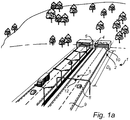
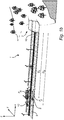
Figs 1a-b schematically show an embodiment of the system according to the invention; -
Fig 2a illustrates the tunnel entrance scene for the image sensor viewing pose; -
Fig 2b illustrates the tunnel entrance scene for the driver viewing pose; -
Fig 3 is a schematic block diagram of the system infigs 1a-b ; -
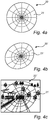
Figs 4a-c schematically illustrate a first embodiment of the veiling luminance estimation method according to the present invention; and -
Figs 5a-c schematically illustrate a second embodiment of the veiling luminance estimation method according to the present invention. -
Fig 1 schematically shows a tunnelillumination control system 1 according to embodiments of the present invention for controlling illumination in aroad tunnel 2. Referring tofig 1a , thesystem 1 comprises at least one light-source 4 arranged inside the road tunnel, a veilingluminance estimation system 5, and alighting controller 6, here schematically illustrated as a box on the interior wall of the road tunnel. - When a
driver 8 traveling on theroad 9 approaches thetunnel entrance 10 of theroad tunnel 2 during daytime, it will be important to illuminate at least the so-called threshold zone of theroad tunnel 2 sufficiently to allow the driver to perceive objects at thetunnel entrance 10 at least from a predefined stopping distance Ds away from thetunnel entrance 10. To achieve this, the light-sources 4 inside theroad tunnel 2 should be controlled to achieve a so-called threshold luminance in the threshold zone. The threshold luminance in turn depends on the veiling luminance experienced by thedriver 8 at the stopping distance Ds from thetunnel entrance 10. - For estimating the veiling luminance, the veiling
luminance estimation system 5 comprises animage sensor 12 arranged above theroad 9. Theimage sensor 12 may advantageously be arranged at a considerably higher vertical position than the driver, as is schematically indicated infig 1a , in order to reduce the risk of vandalism and contamination of theimage sensor 12. Alternatively or in combination, theimage sensor 12 may be laterally offset, so that it is arranged at the side of the road. - In 1b, the traffic scene in
fig 1a is illustrated in a side view to show the difference in perspective for thedriver 8 and theimage sensor 12, respectively. Referring tofig 1b , the driver is shown to be at the above-described stopping distance Ds from thetunnel entrance 10, and theimage sensor 12 is shown to be at an image sensor distance Dis from thetunnel entrance 10. The image sensor distance Dis may advantageously, but not necessarily, be identical to the stopping distance Ds. - The
driver 8 is here shown to exhibit a driver viewing pose Pd defined by at least the driver vertical position zd and the driver viewing direction rd, and theimage sensor 12 is shown to exhibit an image sensor viewing pose Pis defined by at least the image sensor vertical position zis and the image sensor viewing direction r is. Naturally, the driver viewing pose Pd may alternatively be defined by the driver position in space (xd, yd, zd) and the driver viewing direction r d, and the image sensor viewing pose Pis may alternatively be defined by the image sensor position in space (xis, yis, zis) and the image sensor viewing direction r is. The viewing directions r d and r is may, for example, be represented by Euler angles (ϕ, θ, ψ). - As is clear from
figs 1a-b , the tunnel entrance scene will look different for the image sensor viewing pose Pis than for the driver viewing pose Pd. This is illustrated infigs 2a-b , wherefig 2a schematically shows the tunnel entrance view for the image sensor pose Pis, andfig 2b schematically shows the tunnel entrance view for the driver pose Pd. - Comparing
fig 2a and fig 2b , it is easy to understand that the veiling luminance for the image sensor pose Pis (fig 2a ) will be quite different from the veiling luminance for the driver pose Pd (fig 2b ). For instance, the tunnel entrance view for the driver pose Pd (fig 2b ) contains considerably more road surface and sky than the tunnel entrance view for the image sensor pose Pis (fig 2a ). - Before going into further detail concerning embodiments of the method carried out by the tunnel illumination system according to the present invention, an embodiment of the tunnel illumination system will be described in greater detail with reference to the block diagram in
fig 3 . - Referring to
fig 3 , the tunnel illumination system according to embodiments of the present invention comprises a light-source arranged in the road tunnel, a veilingluminance estimation system 5, and alighting controller 6. The veilingluminance estimation system 5 estimates a veiling luminance experienced by a driver exhibiting a driver viewing pose Pd towards the tunnel entrance, and thelighting controller 6 is connected to the veilingluminance estimation system 5 and to the light-source 4 for controlling at least one property of light emitted by the light-source 4 based on the estimated veiling luminance. - The veiling
luminance estimation system 5 comprises animage sensor 12,image acquisition circuitry 14 connected to theimage sensor 12 for acquiring an image of the tunnel entrance scene, and veilingluminance estimation circuitry 15 connected to theimage acquisition circuitry 14 for estimating the veiling luminance for the driver viewing pose based on the acquired image and a relation between the image sensor pose Pis and the driver viewing pose Pd. - In particular, the veiling
luminance estimation circuitry 15 is configured to determine a plurality of pixel sets based on the acquired image, determine, for each pixel set in the plurality of pixel sets, a luminance indicator value indicative of a luminance contribution from a portion of the tunnel entrance scene corresponding to the pixel set, assign an estimation weight to each of the pixel sets, and estimate the veiling luminance based on a weighted sum of the luminance indicator values of each of the pixel sets using the estimation weights. - As will be described below with reference to
figs 4a-c andfigs 5a-c , at least one of the plurality of pixel sets, the luminance indicator value of each of the pixel sets, and the estimation weight assigned to each of the pixel sets is determined based on a relation between the driver viewing pose and the image sensor viewing pose. -
Figs 4a-c schematically illustrate a first embodiment for estimating the veiling luminance for the driver viewing pose Pd based on an image acquired by theimage sensor 12 exhibiting the image sensor viewing pose Pis. - Referring first to
fig 4a , the standard polar diagram 20 as provided by the above-mentioned CIE 88:2004 is shown. As mentioned above, this polar diagram 20 is a graphical and discretized representation of the Holladay-Stiles formula, and the sizes of thesections 21 are chosen to represent the angle dependent weight factor so that the total weight of eachsection 21 is the same, and the luminance contribution from each section can be added together (each section having the same estimation weight). - By superimposing the polar diagram 20 in
fig 4a on the image acquired from theimage sensor 12, forming pixel sets by assigning pixels overlapping with asection 21 to the same pixel set, and summing the luminance contributions from each pixel set/section (with the same estimation weight for each pixel set), the veiling luminance for the image sensor viewing pose Pis can be estimated. - To instead allow estimation of the desired veiling luminance for the driver viewing pose Pd, the standard polar diagram is transformed from the driver viewing pose Pd to the image sensor viewing pose Pis to form a transformed polar diagram 20' with transformed sections 21'.
- According to one example, the transformation can be carried out by utilizing a 3D representation of the scene. The 3D representation can by obtained by for example applying lidar scanning, structure-from-motion and/or stereo vision to images from camera sensors placed at different vantage points. The model can also be provided as a simplified, man-made, representation of the scene.
- Below, the transformation from the image sensor viewing pose to the driver viewing pose is described. As is well-known to the person skilled in the art, the transformation from the driver viewing pose to the image sensor viewing pose is simply the inverse transformation.
- Applying the linear pinhole camera model, a 3D scene point M is projected into the (homogeneous) image point m in the driver's field of view (FOV) as

- Where subscript d indicates driver, and:
- Kd : Given affine matrix (3x3) representing the internal calibration of the camera. Brings a point from image sensor frame to pixel space.
- Rd : Given rotation matrix (3x3). Represents a rotation from the image sensor frame to the global frame. In the driver's camera frame, the optical axis is typically pointing towards the tunnel entrance (gaze direction).
- td: Given translation vector (3x1). Represents the location of the optical center of the driver's view (typically 1.5m above the road).
- Equation (2) can be used to render the driver's FOV provided that a dense 3D model (mesh) along with luminance values for all its points is available.
- If no dense 3D model is available, we may consider a simplified approach where the world is modeled as a single ground plane, extending to infinity in all directions and aligned with the road surface. Noting that our sought transformation involves the transfer between three 3D planes (image sensor plane → world plane → driver image plane) we can find T as the plane-induced transfer homography:

- I: Identity matrix (3x3)
- π: Given normal of the ground plane, e.g. [0 1 0] for the plane y=0.
- By superimposing the transformed polar diagram 20' on the image acquired from the
image sensor 12 as shown infig 4c , and summing the luminance contributions for each section 21' as described above, the veiling luminance for the driver viewing pose Pd can be estimated based on the image acquired from the image sensor and a relation between the driver viewing pose Pd and the image sensor viewing pose Pis. In this particular example embodiment, the plurality of pixel sets (determined by the transformed sections 21') have been determined based on a relation between the driver viewing pose Pd and the image sensor viewing pose Pis. - As is readily understood by a person skilled in the relevant art, the above-described transformation of the standard polar diagram 20 is equivalent to transforming a weight matrix representing the weights in the Holladay-Stiles formula to a transformed weight matrix (with transformed weight elements). To estimate the veiling luminance for the driver viewing pose Pd, the transformed weight elements can be assigned to pixel sets (typically individual pixels) of the acquired image, and the veiling luminance be estimated based on a weighted sum of the luminance indicator values of the pixels sets (pixels) using the transformed weight elements as estimation weights.
- In this case, the estimation weights are thus determined based on a relation between the driver viewing pose Pd and the image sensor viewing pose Pis.
-
Figs 5a-c schematically illustrate a second embodiment for estimating the veiling luminance for the driver viewing pose Pd based on an image acquired by theimage sensor 12 exhibiting the image sensor viewing pose Pis. -
Fig 5a shows theimage 30 acquired by theimage sensor 12 exhibiting the image sensor pose Pis. - This
image 30 is perspective transformed from the image sensor viewing pose Pis to the driver viewing pose Pd to form a transformed image 30' as is schematically shown infig 5b . - The transformed image 30' obviously comprises pixels that are based on the pixels of the acquired
image 30, and on a relation between the driver viewing pose Pd and the image sensor viewing pose Pis. - As is illustrated in
fig 5c , the veiling luminance for the driver viewing pose Pd is finally estimated by superimposing the polar diagram 20 infig 4a on the transformed image 30', forming pixel sets by assigning pixels overlapping with asection 21 to the same pixel set, and summing the luminance contributions from each pixel set/section (with the same estimation weight for each pixel set). - In this example embodiment, the plurality of pixel sets as well as the luminance indicator values of each pixel set (pixels of the transformed image 30' overlapping with the sections 21) have been determined based on a relation between the driver viewing pose Pd and the image sensor viewing pose Pis.
- The person skilled in the art realizes that the present invention by no means is limited to the preferred embodiments described above. On the contrary, many modifications and variations are possible within the scope of the appended claims. In the claims, the word "comprising" does not exclude other elements or steps, and the indefinite article "a" or "an" does not exclude a plurality. A single processor or other unit may fulfill the functions of several items recited in the claims. The mere fact that certain measures are recited in mutually different dependent claims does not indicate that a combination of these measured cannot be used to advantage. A computer program may be stored/distributed on a suitable medium, such as an optical storage medium or a solid-state medium supplied together with or as part of other hardware, but may also be distributed in other forms, such as via the Internet or other wired or wireless telecommunication systems. Any reference signs in the claims should not be construed as limiting the scope.
Claims (14)
- A system (1) for controlling illumination in a road tunnel (2), comprising:at least one light-source (4) arranged inside said road tunnel (2) for illuminating an interior of said road tunnel; characterized in that said system further comprises:is determined based on a relation between said driver viewing pose (Pd) and said image sensor viewing pose (Pis).a veiling luminance estimation system (5) for estimating a veiling luminance experienced by a driver (8) exhibiting a driver viewing pose (Pd) towards a tunnel entrance (10) of said road tunnel (2), said driver viewing pose (Pd) defining at least a driver vertical position and a driver viewing direction (r d); anda lighting controller (6) connected to said veiling luminance estimation system (5) and to said at least one light-source (4) for controlling at least one property of light emitted by said at least one light-source based on said estimated veiling luminance,wherein said veiling luminance estimation system (5) comprises:an image sensor (12) exhibiting an image sensor viewing pose (Pis) towards said tunnel entrance (10), different from said driver viewing pose (Pd), said image sensor viewing pose (Pis) defining at least an image sensor vertical position and an image sensor viewing direction (r is);image acquisition circuitry (14) connected to said image sensor (12) for acquiring an image (30) of a tunnel entrance scene, said image comprising a plurality of pixels; andveiling luminance estimation circuitry (15) connected to said image acquisition circuitry (14) and configured to:determine a plurality of pixel sets based on said image (30);determine, for each pixel set in said plurality of pixel sets, a luminance indicator value indicative of a luminance contribution from a portion of said tunnel entrance scene corresponding to said pixel set;assign an estimation weight to each of said pixel sets; andestimate said veiling luminance based on a weighted sum of the luminance indicator values of each of said pixel sets using said estimation weights,wherein at least one of:said plurality of pixel sets;said luminance indicator value of each of said pixel sets; andsaid estimation weight assigned to each of said pixel sets,
- The system (1) according to claim 1, wherein, for a given viewing distance, said driver viewing pose (Pd) defines a first vertical position, and said image sensor viewing pose (Pis) defines a second vertical position, the second vertical position being higher than the first vertical position.
- The system (1) according to claim 1 or 2, wherein said luminance indicator value is a value indicative of an illuminance sensed by a portion of said image sensor (12) corresponding to said pixel set.
- The system (1) according to any one of the preceding claims,
wherein the determination of at least one of said plurality of pixel sets, said luminance indicator value of each of said pixel sets, and said estimation weight assigned to each of said pixel sets comprises a transformation between said driver viewing pose (Pd) and said image sensor viewing pose (Pis). - The system (1) according to claim 4, wherein said transformation is a perspective transformation.
- The system (1) according to claim 4 or 5, wherein said transformation is applied to at least one of said acquired image, a polar diagram (20) defining said pixel sets (21), and a weight matrix for assigning estimation weights to each of said pixel sets.
- The system (1) according to claim 6, wherein said estimation weight is assigned to each of said pixel sets by:determining a first weight matrix for said driver viewing pose, wherein each weight element in said first weight matrix is inversely proportional to the square of a glare angle with respect to said tunnel entrance (10); andperforming said transformation on said first weight matrix from said driver viewing pose (Pd) to said image sensor viewing pose (Pis), to form a second weight matrix for said image sensor viewing pose (Pis).
- The system (1) according to claim 7, wherein:each of said pixel sets comprises at least one of the pixels of the acquired image; andestimation of said veiling luminance includes multiplying each of said pixel sets with its corresponding weight element in said second weight matrix.
- The system (1) according to claim 6, wherein said plurality of pixel sets is determined by:providing a first polar diagram (20) for said driver viewing pose, defining first sections (21) representing individual glare sources at different glare angles with respect to said tunnel entrance (10);performing said transformation on said first polar diagram from said driver viewing pose (Pd) to said image sensor viewing pose (Pis), to form a second polar diagram (20'), defining second sections (21'), for said image sensor viewing pose (Pis); anddividing the pixels of the acquired image into said pixel sets based on positions of the pixels in relation to said second sections (21').
- The system (1) according to claim 6, wherein said transformation is performed on the acquired image, from said image sensor viewing pose (Pis) to said driver viewing pose (Pd), to form a transformed image having a plurality of pixels being based on the pixels of the acquired image (30).
- A method of estimating a veiling luminance experienced by a driver (8) exhibiting a driver viewing pose (Pd) towards a tunnel entrance (10) of a road tunnel (2), using a veiling luminance estimation system (5) comprising:an image sensor (12) exhibiting an image sensor viewing pose (Pis) towards said tunnel entrance (10), different from said driver viewing pose (Pd);image acquisition circuitry (14) connected to said image sensor (12) for acquiring an image (30) of a tunnel entrance scene, said image comprising a plurality of pixels; andveiling luminance estimation circuitry (15) connected to said image acquisition circuitry (14),wherein the method comprises the steps of:determining, by said veiling luminance estimation circuitry (15), a plurality of pixel sets based on said image (30);determining, by said veiling luminance estimation circuitry (15), for each pixel set in said plurality of pixel sets, a luminance indicator value indicative of a luminance contribution from a portion of said tunnel entrance scene corresponding to said pixel set;assigning, by said veiling luminance estimation circuitry (15), an estimation weight to each of said pixel sets; andestimating, by said veiling luminance estimation circuitry (15), said veiling luminance based on a weighted sum of the luminance indicator values of each of said pixel sets using said estimation weights,wherein at least one of said plurality of pixel sets, said luminance indicator value of each of said pixel sets, and said estimation weight assigned to each of said pixel sets is determined based on a relation between said driver viewing pose (Pd) and said image sensor viewing pose (Pis).
- The method according to claim 11, wherein at least one of:the step of determining said plurality of pixel sets;the step of determining said luminance indicator value of each of said pixel sets; andthe step of assigning an estimation weight to each of said pixel sets,comprises the step of performing a transformation between said driver viewing pose (Pd) and said image sensor viewing pose (Pis).
- The method according to claim 12, wherein said transformation is a perspective transformation.
- A method of controlling illumination in a road tunnel (2) using an illumination control system (1) comprising:at least one light-source (4) arranged inside said road tunnel (2) for illuminating an interior of said road tunnel;a veiling luminance estimation system (5) arranged outside said tunnel (2) for estimating a veiling luminance experienced by a driver (8) exhibiting a driver viewing pose (Pd) towards a tunnel entrance (10) of said road tunnel (2), said veiling luminance estimation system (5) comprising:an image sensor (12) exhibiting an image sensor viewing pose (Pis) towards said tunnel entrance (10), different from said driver viewing pose (Pd);image acquisition circuitry (14) connected to said image sensor (12) for acquiring an image of a tunnel entrance scene, said image comprising a plurality of pixels; andveiling luminance estimation circuitry (15) connected to said image acquisition circuitry (14); anda lighting controller (6) connected to said veiling luminance estimation system (5) and to said at least one light-source (4) for controlling at least one property of light emitted by said at least one light-source based on said estimated veiling luminance,wherein said method comprises the steps of:estimating said veiling luminance experienced by said driver (8) using the method according to any one of claims 11 to 13;providing said estimated veiling luminance to said lighting controller (6); andcontrolling, by said lighting controller (6), said at least one light-source (4) to change at least one property of light emitted by the at least one light-source based on the estimated veiling luminance.
Applications Claiming Priority (1)
| Application Number | Priority Date | Filing Date | Title |
|---|---|---|---|
| SE1551311A SE1551311A1 (en) | 2015-10-09 | 2015-10-09 | System for controlling illumination in a road tunnel and method of estimating a veiling luminance |
Publications (2)
| Publication Number | Publication Date |
|---|---|
| EP3154318A1 EP3154318A1 (en) | 2017-04-12 |
| EP3154318B1 true EP3154318B1 (en) | 2018-08-22 |
Family
ID=57354077
Family Applications (1)
| Application Number | Title | Priority Date | Filing Date |
|---|---|---|---|
| EP16192220.8A Not-in-force EP3154318B1 (en) | 2015-10-09 | 2016-10-04 | System for controlling illumination in a road tunnel and method of estimating a veiling luminance |
Country Status (2)
| Country | Link |
|---|---|
| EP (1) | EP3154318B1 (en) |
| SE (1) | SE1551311A1 (en) |
Families Citing this family (2)
| Publication number | Priority date | Publication date | Assignee | Title |
|---|---|---|---|---|
| CN119212167B (en) * | 2024-11-26 | 2025-05-30 | 江苏雄浦照明电器有限公司 | A tunnel light intelligent control system |
| CN120993713B (en) * | 2025-10-23 | 2025-12-26 | 四川交通职业技术学院 | Tunnel ventilation and illumination intelligent control method based on wireless transmission technology |
Family Cites Families (5)
| Publication number | Priority date | Publication date | Assignee | Title |
|---|---|---|---|---|
| JP4543459B2 (en) * | 1999-11-22 | 2010-09-15 | パナソニック電工株式会社 | Lighting device |
| JP4870665B2 (en) * | 2004-06-30 | 2012-02-08 | コーニンクレッカ フィリップス エレクトロニクス エヌ ヴィ | Dominant color extraction using perceptual rules to generate ambient light derived from video content |
| JP5261952B2 (en) * | 2007-03-27 | 2013-08-14 | 岩崎電気株式会社 | Equivalent screen brightness measuring device, tunnel lighting system and information display system |
| EP3058508A1 (en) * | 2013-10-16 | 2016-08-24 | Cipherstone Technologies AB | Method and system for determining a reflection property of a scene |
| CN104034413A (en) * | 2014-07-03 | 2014-09-10 | 武汉中交交通工程有限责任公司 | Method for measuring brightness outside highway tunnel |
-
2015
- 2015-10-09 SE SE1551311A patent/SE1551311A1/en not_active Application Discontinuation
-
2016
- 2016-10-04 EP EP16192220.8A patent/EP3154318B1/en not_active Not-in-force
Non-Patent Citations (1)
| Title |
|---|
| None * |
Also Published As
| Publication number | Publication date |
|---|---|
| SE1551311A1 (en) | 2017-04-10 |
| EP3154318A1 (en) | 2017-04-12 |
Similar Documents
| Publication | Publication Date | Title |
|---|---|---|
| US20210157329A1 (en) | Systems and methods for positioning vehicles under poor lighting conditions | |
| US10237532B2 (en) | Scan colorization with an uncalibrated camera | |
| CN112640413B (en) | Method, control device and vehicle for displaying a model of surrounding environment | |
| CN101107556B (en) | Method and device for visualizing surrounding environment of automobile by synthesizing infrared image and visible light image | |
| JP6833668B2 (en) | Image feature enhancement device, road surface feature analysis device, image feature enhancement method and road surface feature analysis method | |
| EP3301913A1 (en) | Photographing device and method for acquiring depth information | |
| US10482347B2 (en) | Inspection of the contoured surface of the undercarriage of a motor vehicle | |
| JP7031697B2 (en) | Information processing device and recognition support method | |
| CN104484563B (en) | A method of dynamic evaluation being carried out to road lighting dazzle using imaging brightness meter | |
| EP2723060A1 (en) | Vehicle-mounted camera device | |
| RU2615063C2 (en) | Method and device for detecting moving objects in video image sequence | |
| WO2009110082A1 (en) | Image photographic device, image photographic method, and image photographic program | |
| JP2018048839A (en) | Three-dimensional data generation device, three-dimensional data generation method, and monitoring system including three-dimensional data generation device | |
| JP5261952B2 (en) | Equivalent screen brightness measuring device, tunnel lighting system and information display system | |
| US10769458B2 (en) | Determination procedure of the luminance of traffic signs and device for its embodiment | |
| US10733464B2 (en) | Method, system and device of obtaining 3D-information of objects | |
| CN113962875A (en) | Method and system for enhancing images using machine learning | |
| CN108076332A (en) | The system and method for digital black level mixing | |
| JP3570198B2 (en) | Image processing method and apparatus | |
| EP3154318A1 (en) | System for controlling illumination in a road tunnel and method of estimating a veiling luminance | |
| CN101044390B (en) | Sight distance measuring device and uses | |
| Kudinov et al. | Camera and auxiliary sensor calibration for a multispectral panoramic vision system with a distributed aperture | |
| JP5313080B2 (en) | Linear component reduction device and pedestrian detection display system | |
| RU2534824C2 (en) | Method for entropy-based determination of edge curves of object | |
| JP2019129469A (en) | Image processing device |
Legal Events
| Date | Code | Title | Description |
|---|---|---|---|
| PUAI | Public reference made under article 153(3) epc to a published international application that has entered the european phase |
Free format text: ORIGINAL CODE: 0009012 |
|
| AK | Designated contracting states |
Kind code of ref document: A1 Designated state(s): AL AT BE BG CH CY CZ DE DK EE ES FI FR GB GR HR HU IE IS IT LI LT LU LV MC MK MT NL NO PL PT RO RS SE SI SK SM TR |
|
| AX | Request for extension of the european patent |
Extension state: BA ME |
|
| 17P | Request for examination filed |
Effective date: 20170920 |
|
| RBV | Designated contracting states (corrected) |
Designated state(s): AL AT BE BG CH CY CZ DE DK EE ES FI FR GB GR HR HU IE IS IT LI LT LU LV MC MK MT NL NO PL PT RO RS SE SI SK SM TR |
|
| GRAP | Despatch of communication of intention to grant a patent |
Free format text: ORIGINAL CODE: EPIDOSNIGR1 |
|
| INTG | Intention to grant announced |
Effective date: 20180412 |
|
| GRAS | Grant fee paid |
Free format text: ORIGINAL CODE: EPIDOSNIGR3 |
|
| GRAA | (expected) grant |
Free format text: ORIGINAL CODE: 0009210 |
|
| AK | Designated contracting states |
Kind code of ref document: B1 Designated state(s): AL AT BE BG CH CY CZ DE DK EE ES FI FR GB GR HR HU IE IS IT LI LT LU LV MC MK MT NL NO PL PT RO RS SE SI SK SM TR |
|
| REG | Reference to a national code |
Ref country code: GB Ref legal event code: FG4D |
|
| REG | Reference to a national code |
Ref country code: CH Ref legal event code: EP |
|
| REG | Reference to a national code |
Ref country code: AT Ref legal event code: REF Ref document number: 1034027 Country of ref document: AT Kind code of ref document: T Effective date: 20180915 |
|
| REG | Reference to a national code |
Ref country code: IE Ref legal event code: FG4D |
|
| REG | Reference to a national code |
Ref country code: DE Ref legal event code: R096 Ref document number: 602016004959 Country of ref document: DE |
|
| REG | Reference to a national code |
Ref country code: FR Ref legal event code: PLFP Year of fee payment: 3 |
|
| REG | Reference to a national code |
Ref country code: NL Ref legal event code: MP Effective date: 20180822 |
|
| REG | Reference to a national code |
Ref country code: LT Ref legal event code: MG4D |
|
| REG | Reference to a national code |
Ref country code: NO Ref legal event code: T2 Effective date: 20180822 |
|
| PG25 | Lapsed in a contracting state [announced via postgrant information from national office to epo] |
Ref country code: IS Free format text: LAPSE BECAUSE OF FAILURE TO SUBMIT A TRANSLATION OF THE DESCRIPTION OR TO PAY THE FEE WITHIN THE PRESCRIBED TIME-LIMIT Effective date: 20181222 Ref country code: RS Free format text: LAPSE BECAUSE OF FAILURE TO SUBMIT A TRANSLATION OF THE DESCRIPTION OR TO PAY THE FEE WITHIN THE PRESCRIBED TIME-LIMIT Effective date: 20180822 Ref country code: GR Free format text: LAPSE BECAUSE OF FAILURE TO SUBMIT A TRANSLATION OF THE DESCRIPTION OR TO PAY THE FEE WITHIN THE PRESCRIBED TIME-LIMIT Effective date: 20181123 Ref country code: SE Free format text: LAPSE BECAUSE OF FAILURE TO SUBMIT A TRANSLATION OF THE DESCRIPTION OR TO PAY THE FEE WITHIN THE PRESCRIBED TIME-LIMIT Effective date: 20180822 Ref country code: FI Free format text: LAPSE BECAUSE OF FAILURE TO SUBMIT A TRANSLATION OF THE DESCRIPTION OR TO PAY THE FEE WITHIN THE PRESCRIBED TIME-LIMIT Effective date: 20180822 Ref country code: BG Free format text: LAPSE BECAUSE OF FAILURE TO SUBMIT A TRANSLATION OF THE DESCRIPTION OR TO PAY THE FEE WITHIN THE PRESCRIBED TIME-LIMIT Effective date: 20181122 Ref country code: NL Free format text: LAPSE BECAUSE OF FAILURE TO SUBMIT A TRANSLATION OF THE DESCRIPTION OR TO PAY THE FEE WITHIN THE PRESCRIBED TIME-LIMIT Effective date: 20180822 Ref country code: LT Free format text: LAPSE BECAUSE OF FAILURE TO SUBMIT A TRANSLATION OF THE DESCRIPTION OR TO PAY THE FEE WITHIN THE PRESCRIBED TIME-LIMIT Effective date: 20180822 |
|
| PGFP | Annual fee paid to national office [announced via postgrant information from national office to epo] |
Ref country code: NO Payment date: 20181114 Year of fee payment: 3 Ref country code: DE Payment date: 20181101 Year of fee payment: 3 |
|
| REG | Reference to a national code |
Ref country code: AT Ref legal event code: MK05 Ref document number: 1034027 Country of ref document: AT Kind code of ref document: T Effective date: 20180822 |
|
| PG25 | Lapsed in a contracting state [announced via postgrant information from national office to epo] |
Ref country code: HR Free format text: LAPSE BECAUSE OF FAILURE TO SUBMIT A TRANSLATION OF THE DESCRIPTION OR TO PAY THE FEE WITHIN THE PRESCRIBED TIME-LIMIT Effective date: 20180822 Ref country code: AL Free format text: LAPSE BECAUSE OF FAILURE TO SUBMIT A TRANSLATION OF THE DESCRIPTION OR TO PAY THE FEE WITHIN THE PRESCRIBED TIME-LIMIT Effective date: 20180822 Ref country code: LV Free format text: LAPSE BECAUSE OF FAILURE TO SUBMIT A TRANSLATION OF THE DESCRIPTION OR TO PAY THE FEE WITHIN THE PRESCRIBED TIME-LIMIT Effective date: 20180822 |
|
| PGFP | Annual fee paid to national office [announced via postgrant information from national office to epo] |
Ref country code: GB Payment date: 20181221 Year of fee payment: 11 |
|
| PG25 | Lapsed in a contracting state [announced via postgrant information from national office to epo] |
Ref country code: RO Free format text: LAPSE BECAUSE OF FAILURE TO SUBMIT A TRANSLATION OF THE DESCRIPTION OR TO PAY THE FEE WITHIN THE PRESCRIBED TIME-LIMIT Effective date: 20180822 Ref country code: CZ Free format text: LAPSE BECAUSE OF FAILURE TO SUBMIT A TRANSLATION OF THE DESCRIPTION OR TO PAY THE FEE WITHIN THE PRESCRIBED TIME-LIMIT Effective date: 20180822 Ref country code: PL Free format text: LAPSE BECAUSE OF FAILURE TO SUBMIT A TRANSLATION OF THE DESCRIPTION OR TO PAY THE FEE WITHIN THE PRESCRIBED TIME-LIMIT Effective date: 20180822 Ref country code: ES Free format text: LAPSE BECAUSE OF FAILURE TO SUBMIT A TRANSLATION OF THE DESCRIPTION OR TO PAY THE FEE WITHIN THE PRESCRIBED TIME-LIMIT Effective date: 20180822 Ref country code: AT Free format text: LAPSE BECAUSE OF FAILURE TO SUBMIT A TRANSLATION OF THE DESCRIPTION OR TO PAY THE FEE WITHIN THE PRESCRIBED TIME-LIMIT Effective date: 20180822 Ref country code: EE Free format text: LAPSE BECAUSE OF FAILURE TO SUBMIT A TRANSLATION OF THE DESCRIPTION OR TO PAY THE FEE WITHIN THE PRESCRIBED TIME-LIMIT Effective date: 20180822 |
|
| REG | Reference to a national code |
Ref country code: DE Ref legal event code: R097 Ref document number: 602016004959 Country of ref document: DE |
|
| PG25 | Lapsed in a contracting state [announced via postgrant information from national office to epo] |
Ref country code: SK Free format text: LAPSE BECAUSE OF FAILURE TO SUBMIT A TRANSLATION OF THE DESCRIPTION OR TO PAY THE FEE WITHIN THE PRESCRIBED TIME-LIMIT Effective date: 20180822 Ref country code: DK Free format text: LAPSE BECAUSE OF FAILURE TO SUBMIT A TRANSLATION OF THE DESCRIPTION OR TO PAY THE FEE WITHIN THE PRESCRIBED TIME-LIMIT Effective date: 20180822 Ref country code: SM Free format text: LAPSE BECAUSE OF FAILURE TO SUBMIT A TRANSLATION OF THE DESCRIPTION OR TO PAY THE FEE WITHIN THE PRESCRIBED TIME-LIMIT Effective date: 20180822 |
|
| REG | Reference to a national code |
Ref country code: BE Ref legal event code: MM Effective date: 20181031 |
|
| PG25 | Lapsed in a contracting state [announced via postgrant information from national office to epo] |
Ref country code: MC Free format text: LAPSE BECAUSE OF FAILURE TO SUBMIT A TRANSLATION OF THE DESCRIPTION OR TO PAY THE FEE WITHIN THE PRESCRIBED TIME-LIMIT Effective date: 20180822 Ref country code: LU Free format text: LAPSE BECAUSE OF NON-PAYMENT OF DUE FEES Effective date: 20181004 |
|
| PLBE | No opposition filed within time limit |
Free format text: ORIGINAL CODE: 0009261 |
|
| STAA | Information on the status of an ep patent application or granted ep patent |
Free format text: STATUS: NO OPPOSITION FILED WITHIN TIME LIMIT |
|
| REG | Reference to a national code |
Ref country code: IE Ref legal event code: MM4A |
|
| 26N | No opposition filed |
Effective date: 20190523 |
|
| PG25 | Lapsed in a contracting state [announced via postgrant information from national office to epo] |
Ref country code: BE Free format text: LAPSE BECAUSE OF NON-PAYMENT OF DUE FEES Effective date: 20181031 Ref country code: SI Free format text: LAPSE BECAUSE OF FAILURE TO SUBMIT A TRANSLATION OF THE DESCRIPTION OR TO PAY THE FEE WITHIN THE PRESCRIBED TIME-LIMIT Effective date: 20180822 |
|
| PG25 | Lapsed in a contracting state [announced via postgrant information from national office to epo] |
Ref country code: IE Free format text: LAPSE BECAUSE OF NON-PAYMENT OF DUE FEES Effective date: 20181004 |
|
| PG25 | Lapsed in a contracting state [announced via postgrant information from national office to epo] |
Ref country code: MT Free format text: LAPSE BECAUSE OF NON-PAYMENT OF DUE FEES Effective date: 20181004 |
|
| PGFP | Annual fee paid to national office [announced via postgrant information from national office to epo] |
Ref country code: IT Payment date: 20191031 Year of fee payment: 4 |
|
| PG25 | Lapsed in a contracting state [announced via postgrant information from national office to epo] |
Ref country code: TR Free format text: LAPSE BECAUSE OF FAILURE TO SUBMIT A TRANSLATION OF THE DESCRIPTION OR TO PAY THE FEE WITHIN THE PRESCRIBED TIME-LIMIT Effective date: 20180822 |
|
| REG | Reference to a national code |
Ref country code: DE Ref legal event code: R119 Ref document number: 602016004959 Country of ref document: DE |
|
| REG | Reference to a national code |
Ref country code: NO Ref legal event code: MMEP |
|
| PG25 | Lapsed in a contracting state [announced via postgrant information from national office to epo] |
Ref country code: PT Free format text: LAPSE BECAUSE OF FAILURE TO SUBMIT A TRANSLATION OF THE DESCRIPTION OR TO PAY THE FEE WITHIN THE PRESCRIBED TIME-LIMIT Effective date: 20180822 |
|
| REG | Reference to a national code |
Ref country code: CH Ref legal event code: PL |
|
| PG25 | Lapsed in a contracting state [announced via postgrant information from national office to epo] |
Ref country code: CY Free format text: LAPSE BECAUSE OF FAILURE TO SUBMIT A TRANSLATION OF THE DESCRIPTION OR TO PAY THE FEE WITHIN THE PRESCRIBED TIME-LIMIT Effective date: 20180822 Ref country code: MK Free format text: LAPSE BECAUSE OF NON-PAYMENT OF DUE FEES Effective date: 20180822 Ref country code: HU Free format text: LAPSE BECAUSE OF FAILURE TO SUBMIT A TRANSLATION OF THE DESCRIPTION OR TO PAY THE FEE WITHIN THE PRESCRIBED TIME-LIMIT; INVALID AB INITIO Effective date: 20161004 |
|
| PG25 | Lapsed in a contracting state [announced via postgrant information from national office to epo] |
Ref country code: NO Free format text: LAPSE BECAUSE OF NON-PAYMENT OF DUE FEES Effective date: 20191031 Ref country code: DE Free format text: LAPSE BECAUSE OF NON-PAYMENT OF DUE FEES Effective date: 20200501 Ref country code: CH Free format text: LAPSE BECAUSE OF NON-PAYMENT OF DUE FEES Effective date: 20191031 Ref country code: LI Free format text: LAPSE BECAUSE OF NON-PAYMENT OF DUE FEES Effective date: 20191031 |
|
| PG25 | Lapsed in a contracting state [announced via postgrant information from national office to epo] |
Ref country code: FR Free format text: LAPSE BECAUSE OF NON-PAYMENT OF DUE FEES Effective date: 20191031 |
|
| GBPC | Gb: european patent ceased through non-payment of renewal fee |
Effective date: 20201004 |
|
| PG25 | Lapsed in a contracting state [announced via postgrant information from national office to epo] |
Ref country code: GB Free format text: LAPSE BECAUSE OF NON-PAYMENT OF DUE FEES Effective date: 20201004 |
|
| PG25 | Lapsed in a contracting state [announced via postgrant information from national office to epo] |
Ref country code: IT Free format text: LAPSE BECAUSE OF NON-PAYMENT OF DUE FEES Effective date: 20201004 |