EP3154132A1 - Electrical wire strain relief device and method - Google Patents
Electrical wire strain relief device and method Download PDFInfo
- Publication number
- EP3154132A1 EP3154132A1 EP16192027.7A EP16192027A EP3154132A1 EP 3154132 A1 EP3154132 A1 EP 3154132A1 EP 16192027 A EP16192027 A EP 16192027A EP 3154132 A1 EP3154132 A1 EP 3154132A1
- Authority
- EP
- European Patent Office
- Prior art keywords
- electrical
- connector
- electrical wire
- enlargement
- wire
- Prior art date
- Legal status (The legal status is an assumption and is not a legal conclusion. Google has not performed a legal analysis and makes no representation as to the accuracy of the status listed.)
- Withdrawn
Links
Images
Classifications
-
- H—ELECTRICITY
- H01—ELECTRIC ELEMENTS
- H01R—ELECTRICALLY-CONDUCTIVE CONNECTIONS; STRUCTURAL ASSOCIATIONS OF A PLURALITY OF MUTUALLY-INSULATED ELECTRICAL CONNECTING ELEMENTS; COUPLING DEVICES; CURRENT COLLECTORS
- H01R13/00—Details of coupling devices of the kinds covered by groups H01R12/70 or H01R24/00 - H01R33/00
- H01R13/58—Means for relieving strain on wire connection, e.g. cord grip, for avoiding loosening of connections between wires and terminals within a coupling device terminating a cable
- H01R13/5845—Means for relieving strain on wire connection, e.g. cord grip, for avoiding loosening of connections between wires and terminals within a coupling device terminating a cable the strain relief being achieved by molding parts around cable and connections
-
- H—ELECTRICITY
- H01—ELECTRIC ELEMENTS
- H01R—ELECTRICALLY-CONDUCTIVE CONNECTIONS; STRUCTURAL ASSOCIATIONS OF A PLURALITY OF MUTUALLY-INSULATED ELECTRICAL CONNECTING ELEMENTS; COUPLING DEVICES; CURRENT COLLECTORS
- H01R2201/00—Connectors or connections adapted for particular applications
- H01R2201/26—Connectors or connections adapted for particular applications for vehicles
Definitions
- the present invention relates to electrical devices and, in particular, to a strain relief device and method for preventing wires from separating from an electrical component.
- electrical wires are attached to an electrical source or another element and relay electricity between two components. If the electrical wires become detached from the electrical source or another element that is being supplied electricity, the electrical device will cease operation. Therefore, it is important to ensure the electrical wires do not become detached.
- An electrical connection to reduce strain on electrical wires can include a connector configured to attach to an electrical source at a first end and having a first pin at a second end, a first electrical wire connected to the first pin and having an enlargement at a point along the first electrical wire near the first pin, and a potting bonded to the second end of the connector and surrounding the first pin, a portion of the first electrical wire, and the enlargement along the first electrical wire.
- a method of retaining an electrical wire can include connecting a first electrical wire to a connector, forming a first knot in the first electrical wire at a point near where the first electrical wire connects to the connector, providing slack in the first electrical wire between the first knot and a point where the first electrical wire connects to the connector, and introducing a potting adjacent to the connector such that the potting surrounds the first knot in the first electrical wire.
- An apparatus configured to connect an electrical component to an electrical source which the Applicant expressly reserves the right to claim independently, can include a connector configured to electrically connect to the electrical source, a first wire electrically connected to the connector and configured to electrically connect to the electrical component, a first enlargement on the first wire, and a potting adjacent to the connector and surrounding a portion of the first wire and the first enlargement on the first wire.
- a strain relief device to retain electrical wires includes an enlargement, such as a knot, along the electrical wires to interact with a potting to prevent the electrical wires from becoming separated from an electrical component, such as a connector.
- the potting can be an adhesive, caulking, rubber, hot glue, thermoset plastic, epoxy, or another material that is secured to a structural element and surrounds the enlargement along the electrical wires to prevent the enlargement from being pulled away from and disconnected from the electrical source. Because the electrical wires are usually covered by a nonstick jacket, such as Teflon®, the potting can have difficulty bonding or otherwise being secured to the electrical wires to resist the electrical wires from being pulled through the potting to separate the electrical wires from the potting.
- an enlargement is useful in providing an increased cross-section such that the electrical wires cannot be pulled out through an aperture or conduit in the potting formed by the electrical wires.
- the electrical wires With slack on the electrical wires between the enlargement and the connection of the electrical wires to a component (such as a connector), the electrical wires remain electrically connected to the component/connector, even if an opposite end of the electrical wires is pulled on or vibrated.
- the enlargement can be a knot in the electrical wires, including a single knot, double knot, or an underwriter's knot or another knot that incorporates two or more electrical wires in a knot together.
- the enlargement can be another configuration, such as an additional piece on the electrical wires, an increased thickness of the jacket covering the electrical wires, or braiding of the wires (either as a stand-alone feature, in combination with other knot or knots, or with another configuration as seen in FIG. 2 ).
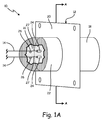
- FIG. 1A is a perspective view of a strain relief device
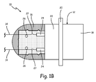
- FIG. 1B is a cross-sectional view of the strain relief device of FIG. 1A taken along line A-A
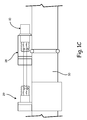
- FIG. 1C is a cross-sectional view of the strain relief device of FIG. 1A adjacent to a valve.
- Strain relief device 10 includes connector 12, electrical wires 14, and potting 16.
- Connector 12 includes mating side 18 (at a first end), flange 20, connection side 22 (at a second end), and pins 24 attached to or incorporated into connection side 22.
- Electrical wires 14 include enlargement 26 and slack 27 and may include a number of diodes near pins 24.
- Strain relief device 10 can be used in conjunction with valve 28 and solenoid 29, which are located along line 30.
- Connector 12 is the main structural element of strain relief device 10 and transmits electricity from an electrical source or another component configured to carry electricity (not shown) to electrical wires 14.
- Connector 12 can transmit electricity either through internal components or by being constructed from a material that is an electrical conductor.
- Connector 12 can be constructed from a variety of materials; including metal (such as aluminum), plastic, or a composite material; and can be one continuous and monolithic piece or made from a number of pieces fastened together.
- Mating side 18 (also referred to as the first end) of connector 12 connects to an electrical source or another component configured to carry electricity. While mating side 18 is shown to have a cylindrical shape, mating side 18 can have a variety of configurations, including a different shape and/or other electrical components (such as wires or pins) to attach to an electrical source.
- Flange 20 of connector 12 extends outward from mating side 18 and connection side 22 to provide a surface for which connector 12 can be fastened to another body, such as valve 28.
- Flange 20 can be fastened to another body through the use of screws, rivets, adhesive, clamps, crimping, soldering, welding, brazing or another fastener. While flange 20 is shown to have a rectangular shape, flange 20 can have a variety of configurations, including a different shape, openings, and/or protrusions that allow flange 20 to be fastened to another body and remain structurally sufficient to support strain relief device 10.
- Connection side 22 (also referred to as the second end) of connector 12 is electrically connected to electrical wires 14 and is adjacent to potting 16.
- Connection side 22 can be electrically connected to electrical wires 14 through pins 24, which can provide a connection point for electrical wires 14 to connect to connector 12.
- Pins 24 can be any other known mechanical means for making connections with metallic or other wires, including a soldered connection with a screw terminal.
- Connection side 22 and pins 24 can be one continuous and monolithic piece or can be fastened to one another through a number of fasteners, including screws, welding, soldering, or other means.
- Connection side 22 should be suited to bond or otherwise secure to potting 16, whether that includes connection side 22 having a rough surface, being constructed from a material that bonds better to potting 16, and/or having another configuration.
- connection side 22 is shown to have a cylindrical shape, connection side 22 can have a variety of configurations, including a different shape and/or other electrical components, to more easily connect to electrical wires 14, bond to potting 16, and interact with valve 28, solenoid 29, and/or another component.
- strain relief device 10 can have a different configuration of connector 12, including a configuration that does not include mating side 18, flange 20, and/or connection side 22.
- Electrical wires 14 electrically connect connector 12 (and the electrical source) to an electrical component in need of electricity, such as valve 28 along line 30.
- Electrical wires 14 can be any wires that are able to transmit electricity between two electrical components. Electrical wires 14 well known in the art usually include a nonstick jacket, such as a Teflon® cover, to insulate electrical wires 14 from the surrounding environment to prevent shorts and protect the wires. Electrical wires 14 can have an element at each end that more easily allows electrical wires 14 to connect to pins 24 and to valve 28 (or another electrical component). Electrical wires 14 can be a variety of sizes/gauges. Additionally, one or multiple diodes or other elements can be present at a point along electrical wires 14. Electrical wires 14 can also be bundled together such that multiple electrical wires 14 are encased together within a casing, such as a tube, jacket, or another protective sheath.
- enlargement 26 is an increase in the cross-sectional area of electrical wires 14 (each separate electrical wire 14 can have an individual enlargement 26; electrical wires 14 can be adjacent to one another such that electrical wires 14 share enlargement 26, such as in FIG. 2 where enlargement 126 is an underwriter's knot incorporating multiple wires; or electrical wires 14 can be encased within one common sheath having enlargement 26).
- Enlargement 26 can be located along electrical wires 14 at a point near pins 24 or can be at a distance away from pins 24, but enlargement 26 should be located along electrical wires 14 at a position where enlargement 26 is surrounded by potting 16 and where potting 16 can be secured to a structural component (either connector 12 or a structural body not shown in the figures).
- Enlargement 26 can be a knot in electrical wires 14 or can be another configuration, such as an additional piece on electrical wires 14 or an increased thickness of electrical wires 14 and/or the jacket covering electrical wires 14. If electrical wires 14 are bundled and encased together, enlargement 26 can be a knot in the entire bundle or another configuration. Additionally, enlargement 26 can be a braiding of electrical wires 14 with one another.
- Braiding electrical wires 14 may reduce the loss of strength of electrical wires 14 that may result from bending electrical wires 14 while also providing enlargement 26. Braiding could also be utilized with other configurations of enlargement 26, including other knots (such as with an underwriter's knot in FIG. 2 and/or a single knot in FIG. 3 ). It may be desirable to have enlargement 26 individually on each one of electrical wires 14 so that electrical wires 14 remain electrically isolated from one another. As mentioned above, enlargement 26 provides an increased cross-sectional area of electrical wires 14 so that electrical wires 14 cannot be pulled out through potting 16 so as to separate from connector 12. The larger the cross-section of enlargement 26, the more resistance strain relief device 10 will have to being pulled out through potting 16.
- Potting 16 can be an adhesive, caulking, rubber, or another material that is bonded or otherwise secured to connection side 22 and surrounds enlargement 26, a portion of electrical wires 14, and pins 24. Potting 16 can be a fluid, such as room temperature vulcanization silicone, that is applied around enlargement 26 and electrical wires 14, bonds to connection side 22, and hardens while potting 16 dries. Potting 16 can also be a hardened material installed around enlargement 26 and electrical wires 14 and is fastened to connection side 22. While potting 16 is shown as being adjacent to connection side 22 and surrounding pins 24, potting 16 and enlargement 26 can be located at a position along electrical wires 14 where potting 16 is secured to another structural body (not shown) and surrounds enlargement 26.
- potting 16 and the jacket/cover on electrical wires 14 can be materials that bond to one another, but are commonly materials that do not bond sufficiently to create a strong hold on one another. Therefore, enlargement 26 is needed to provide resistance against forces that may pull electrical wires away from pins 24 and connection side 22 to disconnect electrical wires 14 from pins 24. If materials are used for potting 16 and the acket/cover that generally bond well, enlargement 26 can still be utilized to provide additional resistance and improved retention of electrical wires 14.
- Strain relief device 10 can be utilized on any machine that has wires that electrically connect two components to one another, such as in FIG. 1C with valve 28 being electrically connected to an electrical source (not shown) and to solenoid 29 (with solenoid 29 able to accommodate an additional strain relief device 10).
- Valve 28 and solenoid 29 can control the flow of a fluid, such as anti-ice fluid, through line 30.
- Valve 28, solenoid 29, and line 30 can be located on an aircraft and thus strain relief device 10 may be subject to strain from experiencing vibration due to movement of the aircraft.
- Strain relief device 10 can also be utilized with solenoid 29 on a valve or another component in an aircraft or in other electromechanical or electronic devices, such as pressure sensors, torque motors, other motors, rotary variable transformers, linear transformers, switches, potentiometers, and other aerospace and non-aerospace applications, including in the automotive, industrial, electronic, and other industries.
- electromechanical or electronic devices such as pressure sensors, torque motors, other motors, rotary variable transformers, linear transformers, switches, potentiometers, and other aerospace and non-aerospace applications, including in the automotive, industrial, electronic, and other industries.
- electrical wires 14 of strain relief device 10 can be subject to strain, which pulls and/or vibrates electrical wires 14.
- the strain can cause electrical wires 14 to become separated from pins 24.
- potting 16 surrounds a portion of electrical wires 14, pins 24, and enlargement 26. Potting 16 can bond to the outer surface of electrical wires 14 to provide some resistance to strain to prevent electrical wires 14 from becoming separated.
- potting 16 surrounds enlargement 26 to prevent enlargement 26 from being pulled away from connection side 22 and pins 24.
- Slack 27 can be present in electrical wires 14 between pins 24 and enlargement 26 to ensure electrical wires 14 do not become separated from pins 24 if potting 16 is elastic and allows enlargement 26 to move a small distance.
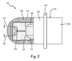
- FIG. 2 is a cross-sectional view of another embodiment of a strain relief device.
- Strain relief device 110 includes connector 112, electrical wires 114, and potting 116.
- Connector 112 includes mating side 118 (at a first end), flange 120, connection side 122 (at a second end), and pins 124 attached to or incorporated into connection side 122.
- Electrical wires 114 include enlargement 126 and slack 127 and may include a number of diodes near pins 124.
- Strain relief device 110 of FIG. 2 is very similar to strain relief device 10 of FIGS. 1A , 1B , and 1C except that enlargement 126 of strain relief device 110 is an underwriter's knot, which is a common electrical knot known in the art to utilize at least two electrical wires 14.
- the use of an underwriter's knot for enlargement 126 may be desirable because an underwriter's knot provides a large enlargement 126, which may make it difficult for electrical wires 114 to be separated from potting 116 and pulled away from connection side 122 and pins 124.
- strain relief device 110, along with potting 116, of FIG. 2 functions similarly as strain relief device 10 of FIGS. 1A , 1B , and 1C .
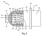
- FIG. 3 is a cross-sectional view of a third embodiment of a strain relief device.
- Strain relief device 210 includes connector 212, electrical wires 214, and potting 216.
- Connector 212 includes mating side 218 (at a first end), flange 220, connection side 222 (at a second end), and pins 224 attached to or incorporated into connection side 222.
- Electrical wires 214 include enlargement 226 and slack 227 and may include a number of diodes near pins 224.
- Strain relief device 210 of FIG. 3 is very similar to strain relief device 10 of FIGS. 1A , 1B , and 1C and strain relief device 110 of FIG. 2 except that strain relief device 210 includes four pins 224 and four electrical wires 214 with four separate enlargements 226. Enlargements 226 are shown as individual single knots, but can each be separate double knots, a knot that incorporates some or all of electrical wires 214, one or multiple underwriter's knots, or another configuration, such as an additional piece on electrical wires 214 or an increased thickness of electrical wires 214. While strain relief device 210 shows four electrical wires 214, the disclosed embodiments can be configured to accommodate any number of electrical wires connected to connector 212 in any type of pattern. Other than having four pins 224 and four electrical wires 214 with four enlargements 226, strain relief device 210, along with potting 216, of FIG. 3 functions similarly as the strain relief devices disclosed in other embodiments.
- the enlargements on the electrical wires in the disclosed embodiments provide additional strain relief (in addition to the strain relief provided by the bonding of the potting to the electrical wires) to prevent the electrical wires from separating from an attached electrical element, such as the pins on the connector.
- An electrical connection can include a connector configured to attach to an electrical source at a first end and having a first pin at a second end, a first electrical wire connected to the first pin and having an enlargement at a point along the first electrical wire near the first pin, and a potting bonded to the second end of the connector and surrounding the first pin, a portion of the first electrical wire, and the enlargement along the first electrical wire.
- the potting is a silicone material.
- the first electrical wire includes slack between the enlargement and the first pin.
- the enlargement of the first electrical wire and the enlargement of the second electrical wire are formed by an underwriter's knot.
- the first electrical wire is connected at an end opposite first pin to a component on an aircraft.
- a method of retaining an electrical wire can include connecting a first electrical wire to a connector, forming a first knot in the first electrical wire at a point near where the first electrical wire connects to the connector, providing slack in the first electrical wire between the first knot and a point where the first electrical wire connects to the connector, and introducing a potting adjacent to the connector such that the potting surrounds the first knot in the first electrical wire.
- the method of retaining an electrical wire of the preceding paragraph can optionally include, additionally and/or alternatively, any one or more of the following features, configurations, steps, and/or additional components:
- Forming a first knot in the first electrical wire and forming a second knot in the second electrical wire includes forming an underwriter's knot.
- the step of introducing a potting adjacent to the connector can further include molding a silicone material to surround the first knot in the first electrical wire.
- An apparatus configured to connect an electrical component to an electrical source can include a connector configured to electrically connect to the electrical source, a first wire electrically connected to the connector and configured to electrically connect to the electrical component, a first enlargement on the first wire, and a potting adjacent to the connector and surrounding a portion of the first wire and the first enlargement on the first wire.
- the apparatus of the preceding paragraph can optionally include, additionally and/or alternatively, any one or more of the following features, configurations, and/or additional components:
- the potting is a room temperature vulcanization silicone material.
- the component is a solenoid in an aircraft.
- the first wire includes slack between the first enlargement and a point where the first wire electrically connects to the connector.
- the first enlargement on the first wire and the second enlargement on the second wire are formed by an underwriter's knot.
- any relative terms or terms of degree used herein, such as “substantially,” “essentially,” “generally,” “approximately,” and the like should be interpreted in accordance with and subject to any applicable definitions or limits expressly stated herein. In all instances, any relative terms or terms of degree used herein should be interpreted to broadly encompass any relevant disclosed embodiments as well as such ranges or variations as would be understood by a person of ordinary skill in the art in view of the entirety of the present disclosure, such as to encompass ordinary manufacturing tolerance variations; incidental alignment variations; alignment or shape variations induced by thermal, rotational, or vibrational operational conditions; and the like.
Landscapes
- Details Of Connecting Devices For Male And Female Coupling (AREA)
- Connector Housings Or Holding Contact Members (AREA)
Abstract
Description
- The present invention relates to electrical devices and, in particular, to a strain relief device and method for preventing wires from separating from an electrical component.
- In electrical devices, electrical wires are attached to an electrical source or another element and relay electricity between two components. If the electrical wires become detached from the electrical source or another element that is being supplied electricity, the electrical device will cease operation. Therefore, it is important to ensure the electrical wires do not become detached.
- An electrical connection to reduce strain on electrical wires can include a connector configured to attach to an electrical source at a first end and having a first pin at a second end, a first electrical wire connected to the first pin and having an enlargement at a point along the first electrical wire near the first pin, and a potting bonded to the second end of the connector and surrounding the first pin, a portion of the first electrical wire, and the enlargement along the first electrical wire.
- A method of retaining an electrical wire can include connecting a first electrical wire to a connector, forming a first knot in the first electrical wire at a point near where the first electrical wire connects to the connector, providing slack in the first electrical wire between the first knot and a point where the first electrical wire connects to the connector, and introducing a potting adjacent to the connector such that the potting surrounds the first knot in the first electrical wire.
- An apparatus configured to connect an electrical component to an electrical source, which the Applicant expressly reserves the right to claim independently, can include a connector configured to electrically connect to the electrical source, a first wire electrically connected to the connector and configured to electrically connect to the electrical component, a first enlargement on the first wire, and a potting adjacent to the connector and surrounding a portion of the first wire and the first enlargement on the first wire.
- The present summary is provided only by way of example and not limitation. Other aspects of the present disclosure will be appreciated in view of the entirety of the present disclosure, including the entire text, claims, and accompanying figures.
-
-
FIG. 1A is a perspective view of a strain relief device. -
FIG. 1B is a cross-sectional view of the strain relief device ofFIG. 1A taken along line A-A. -
FIG. 1C is a cross-sectional view of the strain relief device ofFIG. 1A adjacent to a component in an aircraft. -
FIG. 2 is a cross-sectional view of another embodiment of a strain relief device. -
FIG. 3 is a cross-sectional view of a third embodiment of a strain relief device. - While the above-identified figures set forth embodiments of the present disclosure, other embodiments are also contemplated, as noted in the discussion. In all cases, this disclosure presents the invention by way of representation and not limitation. It should be understood that numerous other modifications and embodiments can be devised by those skilled in the art, which fall within the scope and spirit of the principles of the invention. The figures may not be drawn to scale, and applications and embodiments of the present invention may include features and components not specifically shown in the drawings.
- A strain relief device to retain electrical wires is disclosed herein that includes an enlargement, such as a knot, along the electrical wires to interact with a potting to prevent the electrical wires from becoming separated from an electrical component, such as a connector. The potting can be an adhesive, caulking, rubber, hot glue, thermoset plastic, epoxy, or another material that is secured to a structural element and surrounds the enlargement along the electrical wires to prevent the enlargement from being pulled away from and disconnected from the electrical source. Because the electrical wires are usually covered by a nonstick jacket, such as Teflon®, the potting can have difficulty bonding or otherwise being secured to the electrical wires to resist the electrical wires from being pulled through the potting to separate the electrical wires from the potting. Therefore, an enlargement is useful in providing an increased cross-section such that the electrical wires cannot be pulled out through an aperture or conduit in the potting formed by the electrical wires. With slack on the electrical wires between the enlargement and the connection of the electrical wires to a component (such as a connector), the electrical wires remain electrically connected to the component/connector, even if an opposite end of the electrical wires is pulled on or vibrated. As mentioned above, the enlargement can be a knot in the electrical wires, including a single knot, double knot, or an underwriter's knot or another knot that incorporates two or more electrical wires in a knot together. Additionally, the enlargement can be another configuration, such as an additional piece on the electrical wires, an increased thickness of the jacket covering the electrical wires, or braiding of the wires (either as a stand-alone feature, in combination with other knot or knots, or with another configuration as seen in
FIG. 2 ). -
FIG. 1A is a perspective view of a strain relief device,FIG. 1B is a cross-sectional view of the strain relief device ofFIG. 1A taken along line A-A, andFIG. 1C is a cross-sectional view of the strain relief device ofFIG. 1A adjacent to a valve.Strain relief device 10 includesconnector 12,electrical wires 14, andpotting 16.Connector 12 includes mating side 18 (at a first end),flange 20, connection side 22 (at a second end), andpins 24 attached to or incorporated intoconnection side 22.Electrical wires 14 includeenlargement 26 andslack 27 and may include a number of diodes nearpins 24.Strain relief device 10 can be used in conjunction withvalve 28 andsolenoid 29, which are located alongline 30. -
Connector 12 is the main structural element ofstrain relief device 10 and transmits electricity from an electrical source or another component configured to carry electricity (not shown) toelectrical wires 14.Connector 12 can transmit electricity either through internal components or by being constructed from a material that is an electrical conductor.Connector 12 can be constructed from a variety of materials; including metal (such as aluminum), plastic, or a composite material; and can be one continuous and monolithic piece or made from a number of pieces fastened together. - Mating side 18 (also referred to as the first end) of
connector 12 connects to an electrical source or another component configured to carry electricity. Whilemating side 18 is shown to have a cylindrical shape,mating side 18 can have a variety of configurations, including a different shape and/or other electrical components (such as wires or pins) to attach to an electrical source. -
Flange 20 ofconnector 12 extends outward frommating side 18 andconnection side 22 to provide a surface for whichconnector 12 can be fastened to another body, such asvalve 28.Flange 20 can be fastened to another body through the use of screws, rivets, adhesive, clamps, crimping, soldering, welding, brazing or another fastener. Whileflange 20 is shown to have a rectangular shape,flange 20 can have a variety of configurations, including a different shape, openings, and/or protrusions that allowflange 20 to be fastened to another body and remain structurally sufficient to supportstrain relief device 10. - Connection side 22 (also referred to as the second end) of
connector 12 is electrically connected toelectrical wires 14 and is adjacent to potting 16.Connection side 22 can be electrically connected toelectrical wires 14 throughpins 24, which can provide a connection point forelectrical wires 14 to connect toconnector 12.Pins 24 can be any other known mechanical means for making connections with metallic or other wires, including a soldered connection with a screw terminal.Connection side 22 andpins 24 can be one continuous and monolithic piece or can be fastened to one another through a number of fasteners, including screws, welding, soldering, or other means.Connection side 22 should be suited to bond or otherwise secure to potting 16, whether that includesconnection side 22 having a rough surface, being constructed from a material that bonds better to potting 16, and/or having another configuration. Whileconnection side 22 is shown to have a cylindrical shape,connection side 22 can have a variety of configurations, including a different shape and/or other electrical components, to more easily connect toelectrical wires 14, bond to potting 16, and interact withvalve 28,solenoid 29, and/or another component. - Other embodiments of
strain relief device 10 can have a different configuration ofconnector 12, including a configuration that does not includemating side 18,flange 20, and/orconnection side 22. -
Electrical wires 14 electrically connect connector 12 (and the electrical source) to an electrical component in need of electricity, such asvalve 28 alongline 30.Electrical wires 14 can be any wires that are able to transmit electricity between two electrical components.Electrical wires 14 well known in the art usually include a nonstick jacket, such as a Teflon® cover, to insulateelectrical wires 14 from the surrounding environment to prevent shorts and protect the wires.Electrical wires 14 can have an element at each end that more easily allowselectrical wires 14 to connect topins 24 and to valve 28 (or another electrical component).Electrical wires 14 can be a variety of sizes/gauges. Additionally, one or multiple diodes or other elements can be present at a point alongelectrical wires 14.Electrical wires 14 can also be bundled together such that multipleelectrical wires 14 are encased together within a casing, such as a tube, jacket, or another protective sheath. - Also at a point along
electrical wires 14 isenlargement 26, which is an increase in the cross-sectional area of electrical wires 14 (each separateelectrical wire 14 can have anindividual enlargement 26;electrical wires 14 can be adjacent to one another such thatelectrical wires 14share enlargement 26, such as inFIG. 2 whereenlargement 126 is an underwriter's knot incorporating multiple wires; orelectrical wires 14 can be encased within one common sheath having enlargement 26).Enlargement 26 can be located alongelectrical wires 14 at a point nearpins 24 or can be at a distance away frompins 24, butenlargement 26 should be located alongelectrical wires 14 at a position whereenlargement 26 is surrounded by potting 16 and where potting 16 can be secured to a structural component (eitherconnector 12 or a structural body not shown in the figures).Enlargement 26 can be a knot inelectrical wires 14 or can be another configuration, such as an additional piece onelectrical wires 14 or an increased thickness ofelectrical wires 14 and/or the jacket coveringelectrical wires 14. Ifelectrical wires 14 are bundled and encased together,enlargement 26 can be a knot in the entire bundle or another configuration. Additionally,enlargement 26 can be a braiding ofelectrical wires 14 with one another. Braidingelectrical wires 14 may reduce the loss of strength ofelectrical wires 14 that may result from bendingelectrical wires 14 while also providingenlargement 26. Braiding could also be utilized with other configurations ofenlargement 26, including other knots (such as with an underwriter's knot inFIG. 2 and/or a single knot inFIG. 3 ). It may be desirable to haveenlargement 26 individually on each one ofelectrical wires 14 so thatelectrical wires 14 remain electrically isolated from one another. As mentioned above,enlargement 26 provides an increased cross-sectional area ofelectrical wires 14 so thatelectrical wires 14 cannot be pulled out through potting 16 so as to separate fromconnector 12. The larger the cross-section ofenlargement 26, the more resistancestrain relief device 10 will have to being pulled out throughpotting 16. -
Potting 16 can be an adhesive, caulking, rubber, or another material that is bonded or otherwise secured toconnection side 22 and surroundsenlargement 26, a portion ofelectrical wires 14, and pins 24.Potting 16 can be a fluid, such as room temperature vulcanization silicone, that is applied aroundenlargement 26 andelectrical wires 14, bonds toconnection side 22, and hardens while potting 16 dries.Potting 16 can also be a hardened material installed aroundenlargement 26 andelectrical wires 14 and is fastened toconnection side 22. While potting 16 is shown as being adjacent toconnection side 22 and surroundingpins 24, potting 16 andenlargement 26 can be located at a position alongelectrical wires 14 wherepotting 16 is secured to another structural body (not shown) and surroundsenlargement 26. As mentioned above, potting 16 and the jacket/cover onelectrical wires 14 can be materials that bond to one another, but are commonly materials that do not bond sufficiently to create a strong hold on one another. Therefore,enlargement 26 is needed to provide resistance against forces that may pull electrical wires away frompins 24 andconnection side 22 to disconnectelectrical wires 14 from pins 24. If materials are used for potting 16 and the acket/cover that generally bond well,enlargement 26 can still be utilized to provide additional resistance and improved retention ofelectrical wires 14. -
Strain relief device 10 can be utilized on any machine that has wires that electrically connect two components to one another, such as inFIG. 1C withvalve 28 being electrically connected to an electrical source (not shown) and to solenoid 29 (withsolenoid 29 able to accommodate an additional strain relief device 10).Valve 28 andsolenoid 29 can control the flow of a fluid, such as anti-ice fluid, throughline 30.Valve 28,solenoid 29, andline 30 can be located on an aircraft and thus strainrelief device 10 may be subject to strain from experiencing vibration due to movement of the aircraft.Strain relief device 10 can also be utilized withsolenoid 29 on a valve or another component in an aircraft or in other electromechanical or electronic devices, such as pressure sensors, torque motors, other motors, rotary variable transformers, linear transformers, switches, potentiometers, and other aerospace and non-aerospace applications, including in the automotive, industrial, electronic, and other industries. - As mentioned above,
electrical wires 14 ofstrain relief device 10 can be subject to strain, which pulls and/or vibrateselectrical wires 14. The strain can causeelectrical wires 14 to become separated from pins 24. To preventelectrical wires 14 from becoming separated frompins 24, potting 16 surrounds a portion ofelectrical wires 14, pins 24, andenlargement 26.Potting 16 can bond to the outer surface ofelectrical wires 14 to provide some resistance to strain to preventelectrical wires 14 from becoming separated. To provide additional resistance, potting 16 surroundsenlargement 26 to preventenlargement 26 from being pulled away fromconnection side 22 and pins 24.Slack 27 can be present inelectrical wires 14 betweenpins 24 andenlargement 26 to ensureelectrical wires 14 do not become separated frompins 24 if potting 16 is elastic and allowsenlargement 26 to move a small distance. -
FIG. 2 is a cross-sectional view of another embodiment of a strain relief device.Strain relief device 110 includesconnector 112,electrical wires 114, andpotting 116.Connector 112 includes mating side 118 (at a first end),flange 120, connection side 122 (at a second end), and pins 124 attached to or incorporated intoconnection side 122.Electrical wires 114 includeenlargement 126 and slack 127 and may include a number of diodes near pins 124. -
Strain relief device 110 ofFIG. 2 is very similar tostrain relief device 10 ofFIGS. 1A ,1B , and1C except thatenlargement 126 ofstrain relief device 110 is an underwriter's knot, which is a common electrical knot known in the art to utilize at least twoelectrical wires 14. The use of an underwriter's knot forenlargement 126 may be desirable because an underwriter's knot provides alarge enlargement 126, which may make it difficult forelectrical wires 114 to be separated from potting 116 and pulled away fromconnection side 122 and pins 124. Other than the use of an underwriter's knot forenlargement 126,strain relief device 110, along with potting 116, ofFIG. 2 functions similarly asstrain relief device 10 ofFIGS. 1A ,1B , and1C . -
FIG. 3 is a cross-sectional view of a third embodiment of a strain relief device.Strain relief device 210 includesconnector 212,electrical wires 214, and potting 216.Connector 212 includes mating side 218 (at a first end),flange 220, connection side 222 (at a second end), and pins 224 attached to or incorporated intoconnection side 222.Electrical wires 214 includeenlargement 226 and slack 227 and may include a number of diodes near pins 224. -
Strain relief device 210 ofFIG. 3 is very similar tostrain relief device 10 ofFIGS. 1A ,1B , and1C andstrain relief device 110 ofFIG. 2 except thatstrain relief device 210 includes fourpins 224 and fourelectrical wires 214 with fourseparate enlargements 226.Enlargements 226 are shown as individual single knots, but can each be separate double knots, a knot that incorporates some or all ofelectrical wires 214, one or multiple underwriter's knots, or another configuration, such as an additional piece onelectrical wires 214 or an increased thickness ofelectrical wires 214. Whilestrain relief device 210 shows fourelectrical wires 214, the disclosed embodiments can be configured to accommodate any number of electrical wires connected toconnector 212 in any type of pattern. Other than having fourpins 224 and fourelectrical wires 214 with fourenlargements 226,strain relief device 210, along with potting 216, ofFIG. 3 functions similarly as the strain relief devices disclosed in other embodiments. - As mentioned above, the enlargements on the electrical wires in the disclosed embodiments provide additional strain relief (in addition to the strain relief provided by the bonding of the potting to the electrical wires) to prevent the electrical wires from separating from an attached electrical element, such as the pins on the connector.
- The following are non-exclusive descriptions of possible embodiments of the present invention.
- An electrical connection according to an exemplary embodiment of this disclosure, among other possible elements, can include a connector configured to attach to an electrical source at a first end and having a first pin at a second end, a first electrical wire connected to the first pin and having an enlargement at a point along the first electrical wire near the first pin, and a potting bonded to the second end of the connector and surrounding the first pin, a portion of the first electrical wire, and the enlargement along the first electrical wire.
- The electrical connection of the preceding paragraph can optionally include, additionally and/or alternatively, any one or more of the following features, configurations, and/or additional components:
- The enlargement is a knot in the first electrical wire.
- The potting is a silicone material.
- The first electrical wire includes slack between the enlargement and the first pin.
- A second pin at the second end of the connector and a second electrical wire connected to the second pin and having an enlargement at a point along the second electrical wire near the second pin with the potting also surrounding the second pin, a portion of the second electrical wire, and the enlargement along the second electrical wire.
- The enlargement of the first electrical wire and the enlargement of the second electrical wire are formed by an underwriter's knot.
- The first electrical wire is connected at an end opposite first pin to a component on an aircraft.
- A method of retaining an electrical wire according to an exemplary embodiment of this disclosure, among other possible steps, can include connecting a first electrical wire to a connector, forming a first knot in the first electrical wire at a point near where the first electrical wire connects to the connector, providing slack in the first electrical wire between the first knot and a point where the first electrical wire connects to the connector, and introducing a potting adjacent to the connector such that the potting surrounds the first knot in the first electrical wire.
- The method of retaining an electrical wire of the preceding paragraph can optionally include, additionally and/or alternatively, any one or more of the following features, configurations, steps, and/or additional components:
- Connecting a second electrical wire to the connector, forming a second knot in the second electrical wire at a point near where the second electrical wire connects to the connector, and providing slack in the second electrical wire between the second knot and a point where the second electrical wire connects to the connector with the potting adjacent to the connector also surrounding the second knot in the second electrical wire.
- Forming a first knot in the first electrical wire and forming a second knot in the second electrical wire includes forming an underwriter's knot.
- Connecting an end of the first electrical wire to a component in an aircraft.
- Preventing separation of the first electrical wire from the connector with the potting inhibiting the first knot in the first electrical wire from being pulled away from the connector.
- The step of introducing a potting adjacent to the connector can further include molding a silicone material to surround the first knot in the first electrical wire.
- An apparatus configured to connect an electrical component to an electrical source according to an exemplary embodiment of this disclosure, among other possible elements, can include a connector configured to electrically connect to the electrical source, a first wire electrically connected to the connector and configured to electrically connect to the electrical component, a first enlargement on the first wire, and a potting adjacent to the connector and surrounding a portion of the first wire and the first enlargement on the first wire.
- The apparatus of the preceding paragraph can optionally include, additionally and/or alternatively, any one or more of the following features, configurations, and/or additional components:
- The first enlargement on the first wire is a knot in the first wire.
- The potting is a room temperature vulcanization silicone material.
- The component is a solenoid in an aircraft.
- The first wire includes slack between the first enlargement and a point where the first wire electrically connects to the connector.
- A second wire electrically connected to the connector and configured to electrically connect to the electrical component and a second enlargement on the second wire with the potting adjacent to the connector also surrounding a portion of the second wire and the second enlargement on the first wire.
- The first enlargement on the first wire and the second enlargement on the second wire are formed by an underwriter's knot.
- Any relative terms or terms of degree used herein, such as "substantially," "essentially," "generally," "approximately," and the like should be interpreted in accordance with and subject to any applicable definitions or limits expressly stated herein. In all instances, any relative terms or terms of degree used herein should be interpreted to broadly encompass any relevant disclosed embodiments as well as such ranges or variations as would be understood by a person of ordinary skill in the art in view of the entirety of the present disclosure, such as to encompass ordinary manufacturing tolerance variations; incidental alignment variations; alignment or shape variations induced by thermal, rotational, or vibrational operational conditions; and the like.
- While the invention has been described with reference to exemplary embodiments, it will be understood by those skilled in the art that various changes may be made and equivalents may be substituted for elements thereof without departing from the scope of the invention. In addition, many modifications may be made to adapt a particular situation or material to the teachings of the invention without departing from the essential scope thereof. Therefore, it is intended that the invention not be limited to the particular embodiments disclosed, but that the invention will include all embodiments falling within the scope of the appended claims.
Claims (14)
- An electrical connection comprising:a connector (12;112;212) configured to attach to an electrical source at a first end (18;118;218) and having a first pin (24;124;224) at a second end (22;122;222);a first electrical wire (14;114;214) connected to the first pin (24;124;224) and having an enlargement (26;126;226) at a point along the first electrical wire (14;114;214) near the first pin (24;124;224); anda potting (16;116;216) bonded to the second end (22;122;222) of the connector (12;112;212) and surrounding the first pin (24;124;224), a portion of the first electrical wire (14;114;214), and the enlargement (26;126;226) along the first electrical wire (14;114;214).
- The electrical connection of claim 1, wherein the enlargement (26;126;226) is a knot in the first electrical wire (14;114;214).
- The electrical connection of claim 1 or 2, wherein the potting (16;116;216) is a silicone material.
- The electrical connection of claim 1, 2 or 3, wherein the first electrical wire (14;114;214) includes slack between the enlargement (26;126;226) and the first pin (24;124;224).
- The electrical connection of any preceding claim, further comprising:a second pin (24;124;224) at the second end (22;122;222) of the connector (12;112;212); anda second electrical wire (14;114;214) connected to the second pin (24;124;224) and having an enlargement (26;126;226) at a point along the second electrical wire (124;114;214) near the second pin (24;124;224),wherein the potting (16;116;216) also surrounds the second pin (24;124;224), a portion of the second electrical wire (14;114;214), and the enlargement (26;126;226) along the second electrical wire (14;114;214).
- The electrical connection of claim 5, wherein the enlargement (26;126;226) of the first electrical wire (14;114;214) and the enlargement (26;126;226) of the second electrical wire (14;114;214) are formed by an underwriter's knot.
- The electrical connection of any preceding claim, wherein the first electrical wire (14;114;214) is connected at an end opposite the first pin (24;124;224) to a component on an aircraft.
- A method of retaining an electrical wire (14;114;214), the method comprising:connecting a first electrical wire (14;114;214) to a connector (12;112;212);forming a first knot (26;126;226) in the first electrical wire (14;114;214) at a point near where the first electrical wire (14;114;214) connects to the connector (12;112;212);providing slack in the first electrical wire (14;114;214) between the first knot (26;126;226) and a point where the first electrical wire (14;114;214) connects to the connector (12;112;212); andintroducing a potting (16;116;216) adjacent to the connector (12;112;212) such that the potting (16;116;216) surrounds the first knot in the first electrical wire (14;114;214).
- The method of claim 8, further comprising:connecting a second electrical wire (14;114;214) to the connector (12;112;212);forming a second knot (26;126;226) in the second electrical wire (14;114;214) at a point near where the second electrical wire (14;114;214) connects to the connector (12; 112;212); andproviding slack in the second electrical wire (14;114;214) between the second knot (26;126;226) and a point where the second electrical wire (14;114;214) connects to the connector (12;112;212),wherein the potting (16;116;216) adjacent to the connector (12;112;212) also surrounds the second knot (26;126;226) in the second electrical wire (14;114;214).
- The method of claim 9, wherein forming a first knot (26;126;226) in the first electrical wire (14;114;214) and forming a second knot (26;126;226) in the second electrical wire (14;114;214) includes forming an underwriter's knot.
- The method of claim 8, 9 or 10, further comprising:connecting an end of the first electrical wire (14,114,214) to a component in an aircraft.
- The method of any of claims 8 to 11, further comprising:preventing separation of the first electrical wire (14;114;214) from the connector (12;112;212) with the potting (16;116;216) inhibiting the first knot (26;126;226) in the first electrical wire (14;114;214) from being pulled away from the connector (12;112;212).
- The method of any of claims 8 to 12, wherein the step of introducing a potting (16;116;216) adjacent to the connector (12;112;212) further comprises:molding a silicone material to surround the first knot (26;126;226) in the first electrical wire (14;114;214).
- An apparatus configured to connect an electrical component to an electrical source comprising:a connector (12;112;212) configured to electrically connect to the electrical source;a first wire (14;114;214) electrically connected to the connector (12;112;212) and configured to electrically connect to the electrical component;a first enlargement (26;126;226) on the first wire (14;114;214); anda potting (16;116;216) adjacent to the connector (12;112;212) and surrounding a portion of the first wire (14;114;214) and the first enlargement (26;126;226) on the first wire (14; 114;214).
Applications Claiming Priority (1)
| Application Number | Priority Date | Filing Date | Title |
|---|---|---|---|
| US201514875806A | 2015-10-06 | 2015-10-06 |
Publications (1)
| Publication Number | Publication Date |
|---|---|
| EP3154132A1 true EP3154132A1 (en) | 2017-04-12 |
Family
ID=57178224
Family Applications (1)
| Application Number | Title | Priority Date | Filing Date |
|---|---|---|---|
| EP16192027.7A Withdrawn EP3154132A1 (en) | 2015-10-06 | 2016-10-03 | Electrical wire strain relief device and method |
Country Status (1)
| Country | Link |
|---|---|
| EP (1) | EP3154132A1 (en) |
Citations (2)
| Publication number | Priority date | Publication date | Assignee | Title |
|---|---|---|---|---|
| DE1020395B (en) * | 1953-07-30 | 1957-12-05 | Rheydt Kabelwerk Ag | Strain-relieved fastening of the wires of unreinforced lines or cables under tension in plugs, terminations, sleeves etc. like |
| US6153862A (en) * | 1999-02-26 | 2000-11-28 | Job; Donald D. | Fabric dryer/warmer |
-
2016
- 2016-10-03 EP EP16192027.7A patent/EP3154132A1/en not_active Withdrawn
Patent Citations (2)
| Publication number | Priority date | Publication date | Assignee | Title |
|---|---|---|---|---|
| DE1020395B (en) * | 1953-07-30 | 1957-12-05 | Rheydt Kabelwerk Ag | Strain-relieved fastening of the wires of unreinforced lines or cables under tension in plugs, terminations, sleeves etc. like |
| US6153862A (en) * | 1999-02-26 | 2000-11-28 | Job; Donald D. | Fabric dryer/warmer |
Similar Documents
| Publication | Publication Date | Title |
|---|---|---|
| CN104067468B (en) | Electromagnetic shield and wire harness | |
| US7722362B2 (en) | Sensor adaptor circuit housing incapsulating connection of an input connector with a wire | |
| US8926246B2 (en) | Bolt support structure | |
| EP1571887A2 (en) | Splice connection assembly using heat shrinkable tubing, metal sheathed heater using same, and method of making | |
| JP3768530B2 (en) | Electro-hydraulic pressure regulator, especially electro-hydraulic pressure regulator for vehicle brake devices with slip control function | |
| JP6916201B2 (en) | Manufacturing method of L-type coaxial connector and L-type coaxial connector | |
| JP2019041010A (en) | Resin sealed on-vehicle electronic controller | |
| US20160276758A1 (en) | Electric wire with connecting terminal and method for manufacturing such electric wire | |
| CN106063086A (en) | Electric motors, blowers and compressors | |
| EP2897133B1 (en) | Terminal-formed wire and method for manufacturing said terminal-formed wire | |
| EP3185364A1 (en) | Press-fit terminal | |
| US8022300B2 (en) | Wiring harness | |
| EP3154132A1 (en) | Electrical wire strain relief device and method | |
| EP3035019B1 (en) | Stator slot temperature sensor and assemblying method of the same | |
| US8816711B2 (en) | Electrical probe assembly | |
| EP2763255A1 (en) | Connector | |
| CN107534228B (en) | wire module | |
| US8748748B2 (en) | Clamp assembly and conductive cushion with molded-in grounding foil | |
| JP6556513B2 (en) | Connection structure and wire harness | |
| CN114910104B (en) | Devices, systems and methods for improved sensor line retention | |
| WO2012111759A1 (en) | Exterior component-equipped electric wire and wire harness having said exterior component-equipped electric wire | |
| CN110491653B (en) | Electromagnetic coil unit | |
| JP6613452B2 (en) | Coil parts | |
| CN108701914B (en) | Grounding terminal | |
| JP7699527B2 (en) | CIRCUIT ELEMENT CONNECTION STRUCTURE AND CIRCUIT ELEMENT CONNECTION STRUCTURE UNIT |
Legal Events
| Date | Code | Title | Description |
|---|---|---|---|
| PUAI | Public reference made under article 153(3) epc to a published international application that has entered the european phase |
Free format text: ORIGINAL CODE: 0009012 |
|
| STAA | Information on the status of an ep patent application or granted ep patent |
Free format text: STATUS: THE APPLICATION HAS BEEN PUBLISHED |
|
| AK | Designated contracting states |
Kind code of ref document: A1 Designated state(s): AL AT BE BG CH CY CZ DE DK EE ES FI FR GB GR HR HU IE IS IT LI LT LU LV MC MK MT NL NO PL PT RO RS SE SI SK SM TR |
|
| AX | Request for extension of the european patent |
Extension state: BA ME |
|
| STAA | Information on the status of an ep patent application or granted ep patent |
Free format text: STATUS: REQUEST FOR EXAMINATION WAS MADE |
|
| 17P | Request for examination filed |
Effective date: 20171010 |
|
| RBV | Designated contracting states (corrected) |
Designated state(s): AL AT BE BG CH CY CZ DE DK EE ES FI FR GB GR HR HU IE IS IT LI LT LU LV MC MK MT NL NO PL PT RO RS SE SI SK SM TR |
|
| STAA | Information on the status of an ep patent application or granted ep patent |
Free format text: STATUS: EXAMINATION IS IN PROGRESS |
|
| 17Q | First examination report despatched |
Effective date: 20180403 |
|
| STAA | Information on the status of an ep patent application or granted ep patent |
Free format text: STATUS: THE APPLICATION HAS BEEN WITHDRAWN |
|
| 18W | Application withdrawn |
Effective date: 20180809 |